


Abstract
Background/Objectives: Vascular patches used in cardiovascular reconstruction remain limited by thrombosis, calcification, restricted remodeling, and inability to accommodate somatic growth. This proof-of-concept study aimed to fabricate and characterize porous vascular patches by fused deposition modeling (FDM) using polylactic acid (PLA) and thermoplastic polyurethane (TPU) in single-material and multilayer configurations. Methods: PLA/TPU patches with different polymer compositions, layer sequences, interfilament spacing, and staggered layer arrangements were fabricated by FDM. Mass and dimensional changes during in vitro immersion were assessed for the constituent polymers (n = 3 per polymer) and selected patch configurations (n = 1 per configuration). Patch microstructure and the in-plane dimensions of surface-visible pore openings were evaluated by top-view optical microscopy and ImageJ analysis, while time to first visually detectable fluid passage was assessed using a 22% (w/w) aqueous glycerol test solution under low hydrostatic pressure. Results: PLA and TPU exhibited distinct mass and dimensional profiles during 140 days of immersion, with mean mass increases of 1.37% and 3.68%, respectively. Selected patch specimens showed different temporal mass-change profiles during 42 days of immersion in phosphate-buffered saline (PBS). Descriptive pore measurements varied among the investigated configurations; V7b showed mean dimensions of 96.5 × 93.2 µm. In the exploratory test, fluid passage was first visually detected at 18 min (V5-TPU), 59 min (V6b) and 135 min (V7b). Conclusions: FDM enabled the fabrication of porous PLA/TPU vascular patch prototypes with different material composition and multilayer architectures. These findings establish a preliminary basis for further physicochemical, mechanical, biological, and hemodynamic evaluations of FDM-fabricated PLA/TPU vascular patches.
1. Introduction
Congenital heart diseases (CHDs) are among the most common congenital anomalies, with increasing detection rates associated with advances in clinical screening and imaging techniques [1]. More than half of affected patients require surgical intervention to prevent severe complications, including cyanosis, heart failure, arrhythmias, and other functional impairments, recognized as important clinical manifestations of congenital and developmental cardiac disorders [2].
Vascular patches and conduits are commonly used in the surgical treatment of CHDs. Tetralogy of Fallot, the most prevalent cyanotic congenital heart defect, illustrates the clinical relevance of these reconstructive procedures. In the absence of surgical treatment, life expectancy is markedly reduced, with survival estimated at 66% at one year of age and declining to 11% by 20 years [3,4]. Surgical repair may require enlargement of the right ventricular outflow tract (RVOT) using a patch and, depending on the underlying anatomy and disease severity, reconstruction of stenotic segments of the pulmonary arteries [5]. Vascular conduits are also used in the surgical management of complex CHDs with single-ventricle physiology, including hypoplastic left heart syndrome (HLHS). In the extracardiac Fontan technique, a vascular conduit is used as part of the total cavopulmonary connection, directing systemic venous blood flow toward the pulmonary circulation and providing volume unloading of the single functional ventricle [6].
Currently, materials used for cardiovascular reconstruction include biological patches, such as bovine pericardium, and synthetic substitutes, including polyethylene terephthalate (Dacron®) and expanded polytetrafluoroethylene (ePTFE; Gore-Tex®). Despite their widespread clinical use, these materials have important limitations, including thrombosis, calcification, limited remodeling capacity, and inability to accommodate somatic growth, which are particularly relevant in pediatric patients [7,8,9]. Supporting tissue remodeling and accommodating growth remain important long-term objectives in the development of regenerative vascular substitutes; however, these properties depend on the biological response, material degradation profile, and mechanical behavior of the construct and cannot be inferred from fabrication architecture alone. Such constructs should combine biocompatibility and hemocompatibility with appropriate porous architecture and mechanical properties compatible with the vascular environment [7,8,10,11,12]. In the present study, the investigated PLA/TPU constructs were therefore developed as experimental FDM-fabricated prototypes rather than as growth-accommodating or fully resorbable vascular implants.
Several manufacturing strategies have been investigated for vascular graft and patch fabrication, including three-dimensional (3D) printing [13]. Among these, fused deposition modeling (FDM) is an accessible and cost-effective technique in which thermoplastic filaments are melted and deposited layer by layer according to a computer-aided design (CAD) model [14,15]. By controlling construct geometry, filament orientation, layer arrangement, and internal architecture, FDM enables the fabrication of reproducible structures with predefined characteristics and can facilitate patient-specific designs adapted to complex cardiovascular anatomy [16].
Thermoplastic polymers investigated for FDM-based biomedical applications include polylactic acid (PLA), thermoplastic polyurethane (TPU), and polycaprolactone (PCL) [17,18]. PLA is a slowly hydrolytically degradable polymer that provides structural stability, whereas TPU is a comparatively biostable elastomer characterized by greater flexibility and deformability [19,20,21]. These contrasting properties make PLA and TPU useful materials for investigating multimaterial constructs in which polymer composition and spatial organization can be modified through the printing design. The mechanical behavior of PLA/TPU combinations has also been investigated in blended systems, including their stress–relaxation response [22]. Vellayappan et al. demonstrated the feasibility of fabricating architectured PLA/TPU biomaterials by combining multilayer co-extrusion with FDM, while Abdul Samat et al. investigated porous 3D-printed TPU/PLA scaffolds for tracheal tissue engineering [20,21]. Although PLA and TPU have been investigated individually and in combination in 3D-printed biomedical constructs, their use in FDM-fabricated vascular patches with controlled multilayer architecture remains insufficiently characterized. In particular, the relationships between layer composition and arrangement, in vitro degradation behaviour, pore geometry, and fluid penetration require further investigation.
Therefore, this proof-of-concept study aimed to develop and characterize porous vascular patches fabricated by FDM using PLA and TPU, individually and in multilayer configurations. Specifically, the objectives were to: (1) evaluate the feasibility of fabricating PLA/TPU vascular patches with different layer compositions and architectures; (2) characterize mass and dimensional changes in the constituent polymers and selected patch configurations during in vitro immersion; (3) characterize the pore geometry of the different patch architectures; and (4) evaluate fluid penetration through selected patch configurations. The study was designed as an exploratory, descriptive in vitro investigation intended to provide preliminary data for the further development and characterization of PLA/TPU vascular patches.
2. Materials and Methods
2.1. Study Design
This study was designed as an exploratory, descriptive in vitro proof-of-concept investigation of porous vascular patches fabricated by FDM using PLA and TPU. Different material compositions and multilayer architectures were investigated to characterize fabrication feasibility, mass and dimensional changes during in vitro immersion, pore geometry, and fluid penetration characteristics.
The experimental assessment comprised two levels. First, mass and dimensional changes in the constituent polymers during immersion were evaluated using solid PLA and TPU specimens. Second, selected vascular patch configurations were evaluated to characterize mass changes during immersion, pore geometry, and fluid penetration in relation to polymer composition and layer architecture. Three independently fabricated specimens of each constituent polymer (n = 3) were used for the polymer immersion assessment, whereas one specimen of each selected patch configuration (n = 1) was used for the patch-level assessments. Accordingly, the study was designed to provide preliminary descriptive observations, and no inferential comparisons between materials or patch configurations were performed.
2.2. Vascular Patch Fabrication
Porous vascular patches were fabricated by FDM using PLA and thermoplastic polyurethane (TPU; Shore hardness 95A) filaments with a nominal diameter of 2.85 mm (BASF S.R.L., Bucharest, Romania). The patch geometry was designed using Autodesk Inventor® (Autodesk Inc., San Rafael, CA, USA). The computer-aided design (CAD) models were exported and processed using UltiMaker Cura® (UltiMaker B.V., Utrecht, The Netherlands) to generate the corresponding G-code files, which were subsequently transferred to an Ultimaker S3® dual-extrusion 3D printer (UltiMaker B.V., Utrecht, The Netherlands) for fabrication.
Printing was performed using a 0.4-mm nozzle and a layer height of 0.1 mm. The material-specific extrusion temperature was 223 °C for TPU and 200 °C for PLA. The nominal Cura print-speed setting for TPU was 25 mm/s with 20% cooling and a material flow setting of 106%. The nominal Cura print-speed setting for PLA ranged from 25 to 70 mm/s depending on the patch configuration, with 100% cooling and a material flow setting of 100%; for the V6b and V7b configurations used in the detailed patch assessments, the PLA nominal Cura print speed was 25 mm/s. The build platform was maintained at 60 °C.
The commercially available PLA and TPU filaments were used for experimental prototype fabrication; no medical-grade certification is claimed. The corresponding digital fabrication files are available in the open repository cited in the Data Availability Statement.
2.3. Vascular Patch Characterization
2.3.1. Mass and Dimensional Changes During In Vitro Immersion
Two distinct immersion assessments were performed at different stages of the experimental workflow. The first assessment characterized mass and dimensional changes in the individual constituent polymers, PLA and TPU, whereas the second evaluated selected multilayer vascular patch configurations under different immersion conditions. Because the two assessments differed in specimen type, immersion medium, temperature, and observation period, they were conducted as separate experimental protocols and were not designed for direct quantitative comparison. Mass measurements in both assessments were performed using an Adam AEA 100 analytical balance (Adam Equipment Co. Ltd., Milton Keynes, UK).
- Polymer Assessment
Solid cubic specimens measuring 10 × 10 × 10 mm were fabricated from PLA and TPU by FDM at 100% infill density, using a layer height of 0.1 mm and a brim to improve build stability. Three independently fabricated specimens of each polymer were evaluated (n = 3 per material). The initial mass and three orthogonal dimensions (X, Y, and Z) of each specimen were recorded before immersion in distilled water at room temperature. The specimens were evaluated after 24 h and at 7, 14, 21, 28, 56, 84, 112, and 140 days of immersion. At each time point, the specimens were removed from the immersion medium and dried at room temperature (approximately 22 °C) for 1 h before mass and dimensional measurements were performed. Constant weight was not verified for the cubic specimens. Following each measurement, the distilled water was replaced with fresh medium, and the specimens were returned to their respective containers. Representative figures are provided in Supplementary Figure S1. The pH and exact volume of the distilled water were not recorded. To assess dimensional changes, each cubic specimen was placed on a flat surface, and the three orthogonal dimensions (X, Y, and Z) were measured using a KETOTEK digital caliper (Xiamen, China) (150 mm measuring range; 0.01 mm resolution). The caliper jaws were brought into contact with the specimen without intentional compression. For dimensional analysis, the three orthogonal measurements of each cubic specimen were averaged to obtain one specimen-level dimensional value at each time point.
- 2.
- Vascular Patch Assessment
For the patch-level assessment, PBS at 37 °C was selected to provide a buffered aqueous environment with ionic and pH conditions more relevant to the intended vascular application of the constructs. The PBS had a nominal pH of approximately 7.4.
One specimen from each selected configuration (V5-TPU, V6b, and V7b) was evaluated (n = 1 per configuration). The initial mass of each patch was recorded before immersion in phosphate-buffered saline (PBS) at 37 °C. The specimens were evaluated after 24 h and at 7, 14, 21, 35, and 42 days of immersion. At each time point, the patches were removed from PBS, rinsed with distilled water to remove residual salts, placed in dry containers, and dried at 37 °C in a BIOBASE BOV-T50F (BIOBASE Group, Jinan, China) incubator until a constant weight was achieved. Following each measurement, the PBS was replaced with fresh medium, and the specimens were returned to their respective individual containers. The pH was not serially monitored during the experiment, and the exact immersion-medium volume was not recorded. To describe the changes from baseline in mass and dimensions, the following equation was used:
where X0 represents the baseline value and Xt the value recorded at each subsequent time point.
ΔX (%) = [(Xt − X0)/X0] × 100,
2.3.2. Fluid Penetration Test
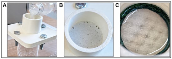
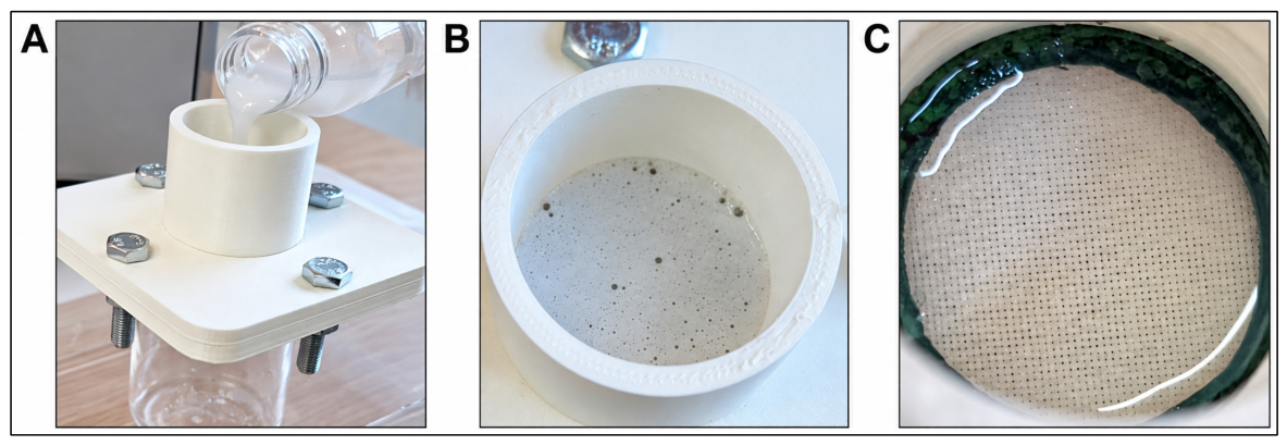
A custom-designed testing device was used for an exploratory comparison of fluid penetration through selected vascular patch configurations (Figure 1).
Figure 1.
Custom-designed device used for the fluid penetration test. (A) Side view of the assembled device during filling with the test solution. (B) Top view of the central cylindrical chamber containing the test solution. (C) Top view of the vascular patch exposed to the test solution within the testing chamber.
The patch specimen was positioned across a circular aperture with an internal diameter of 3 cm and secured between sealing elements to provide circumferential sealing and minimize peripheral leakage. The exposed patch area was 7.07 cm2 and the assembly was secured using four M8 bolts. A 22% (w/w) aqueous glycerol solution was used as the test fluid [23]. The chamber was filled to approximately half of its nominal capacity. The applied solution volume was estimated at approximately 9.5 mL; based on this estimate and the measured internal chamber diameter of 3 cm, the calculated hydrostatic head was approximately 1.35 cm, corresponding to an estimated pressure of approximately 140 Pa (1.05 mmHg). Testing was performed at room temperature under the same conditions for all investigated configurations; room temperature was not continuously monitored or numerically recorded. Timing started immediately after application of the test solution and stopped at the first visually detectable signs of fluid passage through the porous patch structure. Fluid penetration time was recorded in minutes. The assessment was not blinded. One specimen of each selected patch configuration (V5-TPU, V6b, and V7b) was evaluated. The test was intended as an exploratory comparative assessment and was not performed under standardized arterial-pressure conditions.
2.3.3. Microscopy and Pore Measurement
The microstructure of the vascular patches was examined using an Optika B-383 MET® optical microscope (Optika, Italy) equipped with a Nikon D3400 DSLR® camera (Nikon Corporation, Tokyo, Japan; 24.2 MP). Image acquisition was performed using digiCamControl® software (v2.1.6.0). Images were acquired using 4× and 10× objective lenses to examine the morphology and arrangement of the printed filaments, the interfaces between PLA and TPU layers, and the resulting pore architecture.
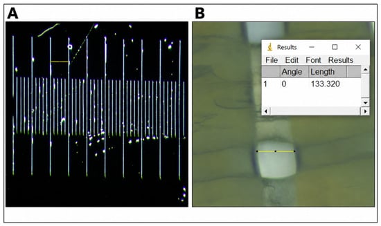
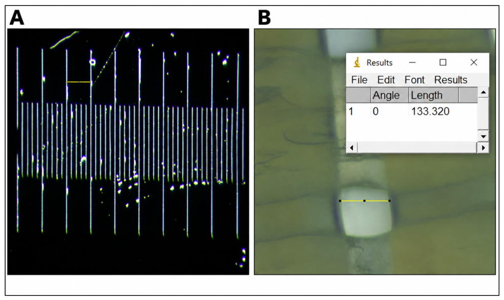
Pore dimensions were quantified using ImageJ® software (v1.54i) (National Institutes of Health, Bethesda, MD, USA) following spatial calibration using a microscopic reference scale. For calibration, images acquired at 4× and 10× magnification included a scale bar, with the distance between two consecutive reference marks set at 100 µm (Figure 2A). The images were imported into the software, and pixel dimensions were converted into micrometers based on this calibration. Because the surface-visible pore openings exhibited a predominantly rectangular geometry, two orthogonal in-plane dimensions, corresponding to pore length and width, were measured (Figure 2B). Measurements were performed on the visible openings between deposited filament structures. For each investigated patch specimen, ten distinct pores were randomly selected from the visible pore field, and both pore length and pore width were measured for each selected pore. Mean pore length and mean pore width, together with the corresponding standard deviations (SDs), were calculated from the ten measurements. These measurements represented technical subsampling within a single patch specimen and were not considered independent experimental replicates.
Figure 2.
Spatial calibration and pore measurement using ImageJ. (A) Reference scale used for spatial calibration, with the selected calibration interval corresponding to 100 µm. (B) Representative measurement of a surface-visible pore dimension in a vascular patch using ImageJ.
2.4. Data Analysis
Given the exploratory, descriptive proof-of-concept design, no inferential statistical analyses were performed. For the polymer immersion assessment, mass and specimen-level dimensional values are presented as mean ± standard deviation (SD) across three independently fabricated specimens per material (n = 3). For dimensional analysis, the three orthogonal dimensions of each specimen were first averaged to obtain one specimen-level value at each time point. Changes from baseline were calculated from the group mean values. For the vascular patch assessments, one specimen of each selected configuration was evaluated (n = 1 per configuration); therefore, patch-level mass, pore, and fluid penetration data were analyzed descriptively and were not used for inferential comparisons between configurations. For pore measurements, ten randomly selected pores were measured within each investigated patch specimen, and pore length and width are presented as mean ± standard deviation (SD). These measurements represented technical subsampling within a single specimen and were not considered independent experimental replicates; therefore, no inferential statistical comparisons between patch configurations were performed. Fluid penetration time was reported descriptively for each tested patch configuration.
3. Results
3.1. Vascular Patch Fabrication and Structural Characteristics
A series of PLA, TPU, and multilayer PLA/TPU vascular patch configurations were fabricated by FDM. The configurations differed in polymer composition, number and sequence of layers, interfilament spacing, and layer offset. The main design and fabrication characteristics of the investigated variants are summarized in Table 1.
Table 1.
Design and fabrication characteristics of the vascular patch configurations.
The initial V1 and V2 configurations were developed as four-layer prototypes with nominal dimensions of 10 × 10 × 0.4 mm. The two configurations differed in interfilament spacing, which was 0.1 mm for V1 and 0.2 mm for V2. Successive layers were oriented orthogonally, with a 90° rotation between adjacent layers. Both V1 and V2 were fabricated separately as entirely PLA and entirely TPU patches, with a printing time of approximately 3 min for V1 and 2 min for V2. During qualitative handling and suture-placement assessment, the TPU patches could be penetrated with a surgical needle and accommodated suture placement without apparent loss of structural continuity. In contrast, the PLA patches exhibited greater rigidity during manual handling and needle passage, which limited suture placement under the conditions evaluated. No quantitative suture-retention or pull-out testing was performed. V3 retained the 0.2-mm interfilament spacing of V2 but was scaled to nominal dimensions of 40 × 40 × 0.8 mm and increased from four to eight layers. Separate entirely PLA and entirely TPU patches were fabricated. The printing time increased to approximately 15 min per patch. V4 maintained the dimensions and interfilament spacing of V3 but incorporated both polymers within an eight-layer architecture. Odd-numbered layers (1, 3, 5, and 7) were fabricated from PLA and even-numbered layers (2, 4, 6, and 8) from TPU, with the PLA and TPU layers oriented perpendicular to each other. The printing time was approximately 18 min.
Two V5 configurations were fabricated with dimensions of 40.4 × 40.4 × 0.9 mm, an interfilament spacing of 0.1 mm, and a total of nine layers. V5-PLA/TPU consisted of alternating PLA and TPU layers, with PLA in layers 1, 3, 5, 7, and 9 and TPU in layers 2, 4, 6, and 8. A second configuration, designated V5-TPU in the present study to distinguish it from the multilayer PLA/TPU configuration, was fabricated entirely from TPU while retaining the V5 architecture. The layers were horizontally aligned, without displacement along the X- or Y-axis. The printing time was approximately 24 min for V5-PLA/TPU and 19 min for V5-TPU respectively.
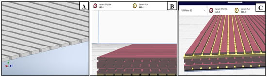
In V6, V6b, V7, and V7b, staggered layer positioning was introduced. V6 and V6b consisted of eight layers, with the first layer fabricated from PLA and layers 2–8 from TPU. The horizontal displacement magnitude was 0.1 mm for V6 (Figure 3B) and 0.2 mm for V6b. Displacement was applied along the X-axis for even-numbered layers and along the Y-axis for odd-numbered layers, relative to the preceding layer of the same parity. The first two layers remained horizontally aligned, and the staggered positioning was introduced from the third layer onward. Along the Z-axis, successive layers were positioned at 0.1-mm increments.
Figure 3.
Design and fabrication of selected vascular patch configurations. (A) CAD representation of a single patch layer showing the parallel arrangement of rectangular elements measuring 40 × 0.4 × 0.1 mm. (B) Sliced representation of the eight-layer V6 architecture comprising an initial PLA layer followed by seven TPU layers. (C) Sliced representation of the nine-layer V7 architecture comprising an initial PLA layer, followed by six TPU layers, an additional PLA layer in the penultimate position, and a final TPU layer.
V7 and V7b consisted of nine layers, with PLA in layers 1 and 8 and TPU in layers 2–7 and 9. The same displacement pattern was applied, using a horizontal offset of 0.1 mm for V7 (Figure 3C) and 0.2 mm for V7b. The two PLA layers were oriented perpendicular to each other, with one aligned along the X-axis and the other along the Y-axis. The printing time was approximately 17 min for V6 and 20 min for V6b, whereas for V7 and V7b was approximately 26 min for each patch. Representative CAD models and sliced multilayer architectures are shown in Figure 3. Representative examples of the V5-TPU, V6b, and V7b configurations following qualitative surgical handling and suture-placement assessment are shown in Supplementary Figure S2.
3.2. Mass and Dimensional Changes During In Vitro Immersion
3.2.1. Polymer Assessment
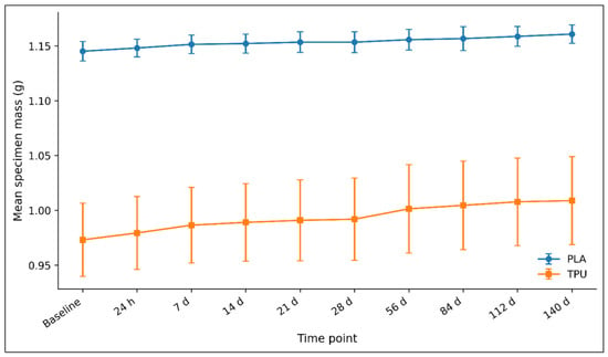
During the 140-day immersion period, the mean mass of both PLA and TPU specimens remained slightly above baseline, with different magnitudes and temporal profiles between the two materials (Table 2; Figure 4).
Table 2.
Mean mass changes in PLA and TPU cubic specimens during immersion in distilled water.
Figure 4.
Time-dependent changes in PLA and TPU specimen mass during 140 days of immersion in distilled water. Values are presented as mean ± SD (n = 3 independent specimens per material).
The mean PLA mass increased from 1.1452 g at baseline to 1.1481 g after 24 h and showed only small subsequent changes, reaching 1.1608 g at day 140. This corresponded to a mean mass change of +1.37% relative to the baseline group mean.
The mean TPU mass increased from 0.9731 g at baseline to 0.9794 g after 24 h and remained above baseline throughout the observation period, reaching 1.0089 g at day 140. The corresponding mean mass change from baseline at day 140 was +3.68%.
Thus, the mean mass change observed during immersion was larger for TPU than for PLA. However, variability among the three independent specimens was evident, particularly for TPU. No net decrease in mean mass relative to baseline was observed for either polymer during the 140-day observation period.
These gravimetric changes were interpreted as changes occurring during aqueous immersion rather than as direct evidence of polymer degradation.
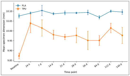
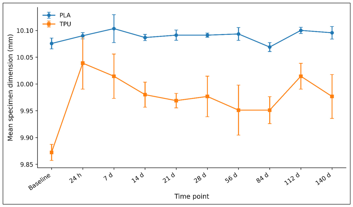
Dimensional measurements also showed different temporal profiles for PLA and TPU specimens (Table 3; Figure 5). During the first 24 h, the mean PLA dimension changed from 10.0756 at baseline to 10.0900 mm, corresponding to an increase of approximately +0.14%. The maximum mean value was recorded at day 7 (10.103 mm; approximately +0.28% relative to baseline). Thereafter, PLA showed only small fluctuations around its initial dimensions. Mean dimensional changes remained within approximately −0.07% to +0.28% relative to baseline throughout the 140-day period. At day 140, the mean PLA dimension was 10.096 mm, corresponding to approximately +0.20% relative to baseline. Given their small magnitude, these PLA dimensional fluctuations should be interpreted in relation to the 0.01 mm instrument resolution and the inherent variability of the contact-based measurement method.
Table 3.
Dimensional changes in PLA and TPU cubic specimens during immersion in distilled water.
Figure 5.
Time-dependent changes in the mean dimensions of PLA and TPU specimens during 140 days of immersion in distilled water. For each specimen, the three orthogonal dimensions were averaged to obtain one specimen-level value. Data are presented as mean ± SD (n = 3 independent specimens per material).
TPU exhibited larger mean dimensional variations. Despite these fluctuations, the TPU dimension remained above its baseline value at the end of the 140-day observation period (+1.06%). Its mean dimension increased from 9.872 mm at baseline to 10.039 mm after 24 h, corresponding to approximately +1.69%. Subsequent measurements showed fluctuations rather than a sustained directional change, with mean values remaining above baseline throughout the observation period. At day 140, the mean TPU dimension was 9.977 mm, corresponding to approximately +1.06% relative to baseline. Overall, the TPU specimens showed a greater magnitude of mean dimensional change during immersion than PLA specimens. Neither material demonstrated a sustained reduction in mean dimensions over the 140-day observation period.
3.2.2. Vascular Patch Assessment
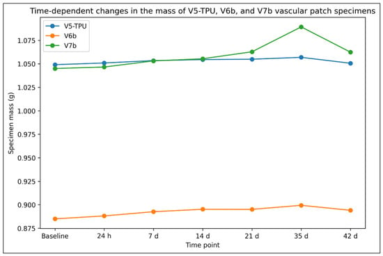
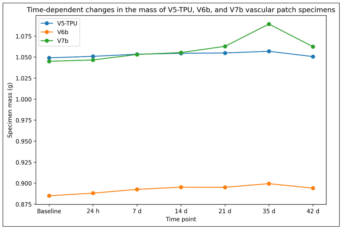
During the 42-day immersion period, temporal mass changes were observed in the individual V5-TPU, V6b, and V7b specimens (Table 4; Figure 6).
Table 4.
Mass changes in individual V5-TPU, V6b, and V7b vascular patch specimens during immersion in PBS at 37 °C.
Figure 6.
Time-dependent changes in the mass of the individual V5-TPU, V6b, and V7b vascular patch specimens during 42 days of immersion in PBS at 37 °C. One specimen was evaluated per configuration (n = 1).
The V5-TPU specimen mass increased from 1.0491 g at baseline to 1.0569 g at day 35 (+0.74%) and subsequently measured 1.0506 g at day 42 (+0.14% relative to baseline). The V6b specimen increased from 0.8850 g at baseline to 0.8994 g at day 35 (+1.63%) and measured 0.8941 g at day 42 (+1.03% relative to baseline).
The V7b specimen mass increased from 1.0450 g at baseline to 1.0893 g at day 35 (+4.24%) and subsequently measured 1.0624 g at day 42 (+1.67% relative to baseline). Thus, each individual specimen remained above its respective baseline mass at the end of the 42-day observation period. Because only one specimen of each patch configuration was evaluated, these observations are descriptive and are not intended to establish reproducible differences between patch configurations.
3.3. Fluid Penetration Test
Fluid penetration was evaluated in the same three patch configurations included in the patch immersion assessment: V5-TPU, V6b, and V7b. Using the exploratory gravity-driven test described above, the elapsed time from application of the 22% (w/w) aqueous glycerol solution to the first visually detectable signs of fluid passage through the patch was recorded for each specimen.
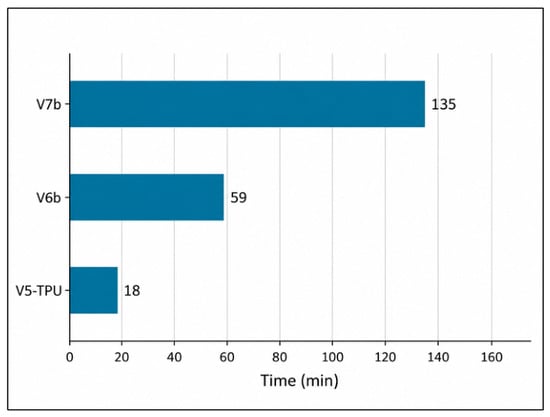
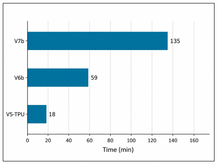
Fluid penetration time differed among the three tested configurations. V5-TPU exhibited the shortest penetration time, with fluid passage first observed after 18 min. V6b showed an intermediate penetration time of 59 min, whereas V7b exhibited the longest penetration time, with fluid passage first observed after 135 min (Figure 7).
Figure 7.
Time to first visually detectable fluid passage recorded for V5-TPU, V6b, and V7b vascular patch configurations during the exploratory gravity-driven fluid penetration test. One specimen was evaluated per configuration (n = 1).
These values represent descriptive times to first visually detectable fluid passage under the present low-hydrostatic-pressure test conditions and should not be interpreted as standardized pressure-controlled measurements of vascular patch permeability.
3.4. Microscopy and Pore Measurement
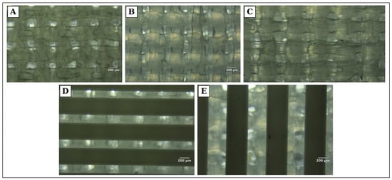
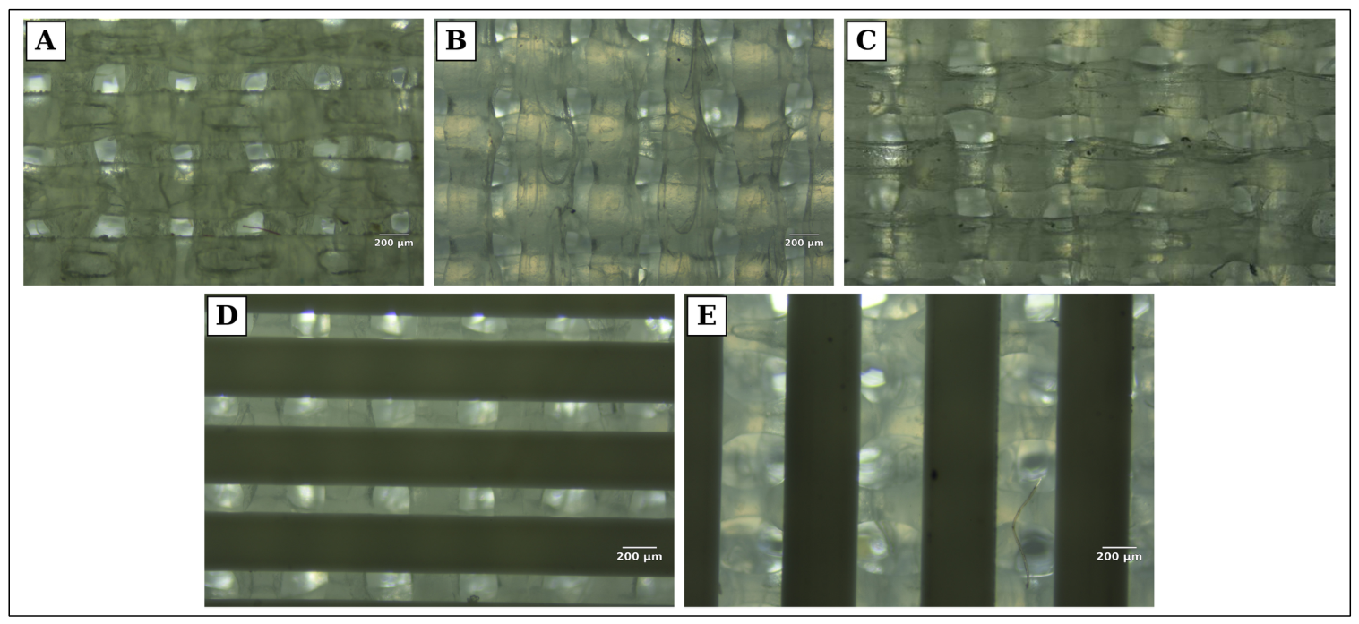
Optical microscopy revealed differences in filament arrangement and pore geometry among the investigated patch configurations. The entirely TPU configuration (V5-TPU) exhibited less regular filament contours and greater apparent variability in pore shape, whereas PLA-containing configurations showed more defined filament boundaries and a more organized pore architecture. The optical micrographs represent top-view surface projections; therefore, the measured values correspond to the in-plane length and width of surface-visible openings and do not represent through-thickness pore dimensions. Representative micrographs of V5-TPU, V6, V6b, V7 and V7b are shown in Figure 8.
Figure 8.
Representative top-view reflected-light optical micrographs of selected vascular patch configurations: (A) V5-TPU; (B) V6; (C) V6b; (D) V7; (E) V7b. The visible openings between deposited filament structures were evaluated in-plane by optical microscopy and ImageJ analysis. The reported measurements represent the in-plane length and width of surface-visible openings and do not represent through-thickness pore dimensions. Images were acquired using a 4× objective. Panel (C) reproduces a previously documented V6b micrograph. Scale bars = 200 µm in panels (A,B,D,E).
Descriptive pore measurements varied among the investigated configurations (Table 5).
Table 5.
Mean pore dimensions of the investigated vascular patch configurations measured by optical microscopy and ImageJ analysis.
A marked design-to-print difference was observed for the V3 configurations. Although V3-PLA and V3-TPU were designed with the same nominal interfilament spacing of 0.2 mm (200 µm), their measured surface-visible opening dimensions differed substantially. V3-PLA showed mean dimensions of 100 ± 2.21 × 116 ± 4.14 µm, corresponding to values approximately 50% and 42% below the nominal spacing, whereas V3-TPU showed mean dimensions of 293 ± 5.24 × 295 ± 5.71 µm, approximately 47% above the nominal spacing in both measured directions. Thus, the nominal CAD interfilament spacing did not translate directly into an equivalent surface-visible opening dimension after printing. Representative micrographs of V3-PLA and V3-TPU are shown in Supplementary Figure S3.
Among the later multilayer configurations, V6 and V6b showed similar mean pore lengths of 172 ± 5.83 µm and 169 ± 3.19 µm, respectively, while the corresponding mean pore widths were 165 ± 5.09 µm and 153 ± 4.17 µm. For V7, mean pore length and width were 157 ± 3.56 µm and 143 ± 3.40 µm, respectively; for V7b, the corresponding values were 96.5 ± 2.77 µm and 93.2 ± 3.03 µm. V7b showed the smallest mean pore dimensions among the investigated configurations. Because these measurements represented technical subsampling within single specimens, the values were interpreted descriptively and were not used for inferential comparisons between configurations.
4. Discussion
4.1. Requirements for Vascular Scaffolds and the Role of 3D Printing
The development of tissue-engineered vascular substitutes requires consideration of several interdependent material and structural characteristics, including biocompatibility, hemocompatibility, mechanical compatibility with the native vessel, porosity, and appropriate stability or degradation behaviour under physiological conditions. For biodegradable constructs, preservation of structural integrity during the intended functional period is particularly important, while progressive material degradation should occur without generating adverse biological effects. Mechanical mismatch between vascular substitutes and native vessels also remains an important consideration, particularly for small-diameter applications [7,8,10,12,19,24,25].
Additive manufacturing offers specific advantages for vascular scaffold fabrication because both macroscopic geometry and internal architecture can be defined during the manufacturing process. Material-extrusion techniques such as FDM enable control over filament orientation, layer sequence, interfilament spacing, and the spatial arrangement of successive layers [13,26,27]. This manufacturing flexibility also enables different polymers to be incorporated within predefined architectures. In addition to architectural design, FDM processing parameters can influence the mechanical behavior of printed PLA and TPU components [28,29]. In the cardiovascular field, Guerra et al. demonstrated the feasibility of combining PCL and PLA by FDM to produce composite stents with material-dependent degradation and mechanical characteristics [18]. More recently, Vellayappan et al. demonstrated that controlled multilayer PLA/TPU architectures can be retained during additive manufacturing, supporting the feasibility of producing architectured constructs from this polymer combination [20].
Within this framework, the present study investigated PLA and TPU individually and in predefined multilayer configurations, using variations in polymer composition, layer sequence, interfilament spacing, and layer displacement to examine immersion-related mass and dimensional changes, pore geometry, and time to first visually detectable fluid passage under the exploratory test conditions.
4.2. Material Selection and In Vitro Immersion Response of PLA and TPU
PLA and TPU were selected based on their distinct material characteristics and suitability for additive manufacturing. PLA is a slowly hydrolytically degradable and hydrophobic polymer widely used in biomedical applications [24,30]. Its degradation occurs primarily through hydrolysis of ester bonds and may extend over prolonged periods, depending on material- and environment-specific factors such as molecular weight, crystallinity, specimen geometry, and water accessibility [24,30]. The incorporation of more hydrophilic polymers, such as polyglycolic acid (PGA), can accelerate degradation by facilitating water penetration and ester bond cleavage [25]. The degree of crystallinity also influences the mechanical and degradation behaviour of PLA, with higher crystallinity generally associated with reduced flexibility and slower water penetration into the polymer matrix [31].
In contrast, TPU is a comparatively biostable elastomer characterized by high elasticity, deformability, and tunable mechanical properties, characteristics that are particularly relevant for cardiovascular applications requiring compliant constructs [24,32]. Although TPU can undergo physicochemical changes and degradation under specific hydrolytic or oxidative conditions, it is not considered a rapidly resorbable polymer [33]. Its role in the present multilayer constructs was therefore primarily related to its elastic and handling characteristics rather than to an expectation of rapid biodegradation. TPU has also been investigated for the additive manufacturing of vascular implants and small-diameter vascular grafts. Vanden Broeck et al. evaluated 3D-printed TPU intended for vascular applications, while Chand et al. recently demonstrated that TPU hardness influences both the compliance and printability of material-extrusion small-diameter vascular grafts [33,34]. These contrasting material characteristics provided the rationale for evaluating PLA and TPU both individually and within the multilayer patch configurations investigated in the present study.
The qualitative surgical handling assessment also influenced the subsequent design strategy. Entirely PLA prototypes exhibited excessive rigidity and limited needle passage and suture placement, whereas TPU-rich constructs were more amenable to handling, needle passage, and suture placement. Architectures containing more than two PLA layers were similarly considered too rigid for the intended handling characteristics. Consequently, the later V6, V6b, V7, and V7b designs incorporated only one or two PLA layers within predominantly TPU architectures. These observations were qualitative and should not be interpreted as standardized measurements of suturability or suture-retention strength.
The different responses of the two polymers were evident during the 140-day immersion assessment. TPU showed a greater overall mass increase than PLA and a larger early dimensional increase, followed by subsequent fluctuations, while neither material exhibited a sustained reduction in mean mass or dimensions relative to baseline. The early dimensional changes observed for TPU should therefore be interpreted as temporal variations in the measured dimensions rather than as evidence of a defined swelling–shrinkage process. The observed net mass increases are consistent with fluid uptake and/or retention during immersion; however, gravimetric and dimensional changes alone cannot establish polymer degradation.
For PLA-based materials, hydrolytic degradation is influenced by multiple material and environmental factors, including molecular weight, crystallinity, specimen geometry, and water accessibility [24,35,36,37]. This distinction is also supported by Vanden Broeck et al., who showed that degradation-related changes in 3D-printed TPU under accelerated hydrolytic and oxidative conditions could be detected by complementary physicochemical and mechanical analyses without pronounced gross mass loss [33].
Differences in the degradation-related behaviour of PLA- and TPU-containing 3D-printed constructs have also been reported by Abdul Samat et al. In their study of 3D-printed scaffolds for tracheal tissue engineering, TPU exhibited greater degradation than PLA during the investigated period, while the TPU/PLA formulation showed an intermediate response [21]. Although the material formulation, scaffold geometry, experimental conditions, and intended application differed from those of the present study, their findings further illustrate that PLA- and TPU-containing constructs can exhibit distinct responses under in vitro conditions.
4.3. Mass Changes in Multilayer Vascular Patches During In Vitro Immersion
At the patch level, V5-TPU, V6b, and V7b exhibited distinct temporal mass profiles during 42 days of immersion in PBS at 37 °C. All three configurations showed an overall increase in mass up to day 35, followed by a decrease between days 35 and 42, while remaining above baseline at the end of the observation period. Among the three tested specimens, the entirely TPU configuration (V5-TPU) showed the smallest magnitude of mass change, whereas V7b, which incorporated two PLA layers within a predominantly TPU architecture, exhibited the largest change. These observations do not support a simple relationship between TPU content and the magnitude of mass change during immersion.
The increase in patch mass observed during most of the immersion period, as well as the subsequent decrease during the final interval, should be interpreted as temporal mass changes rather than direct measures of degradation rate. Although the patches were rinsed with distilled water after removal from PBS and dried at 37 °C until constant weight was achieved, vacuum drying was not used; therefore, residual fluid and/or ionic material retained within the porous structures cannot be completely excluded as contributors to the measured mass variations. Accordingly, the larger mass increase observed for V7b at day 35 and the decrease observed in all three specimens between days 35 and 42 should not be interpreted as evidence of a specific degradation process or intrinsic material response. Fluid uptake and/or retention during immersion may contribute to the observed mass changes, while hydrolytic or other physicochemical changes may occur concurrently; macroscopic mass variation alone cannot distinguish these processes. Consistent with this distinction, Vanden Broeck et al. showed that degradation-related changes in 3D-printed TPU under accelerated hydrolytic and oxidative conditions could be detected by complementary physicochemical and mechanical analyses without pronounced macroscopic mass loss [33].
Overall, the three tested configurations showed different mass-change profiles during immersion. Because they differed simultaneously in polymer composition, layer count, and horizontal offset, the observed differences cannot be attributed to any single design parameter and should be interpreted at the level of the complete patch configuration.
4.4. Layer Architecture, Pore Geometry and Fluid Penetration
Structural characterization showed that the dimensions of surface-visible pore openings varied among the investigated patch architectures. Optical microscopy showed pore openings generated by the orthogonal arrangement of deposited filaments, while quantitative measurements demonstrated differences in their in-plane dimensions among configurations. These findings are consistent with previous additive-manufacturing studies demonstrating that structural features can be modified through the design and fabrication strategy [26,38].
The descriptive pore measurements indicate that the effect of architectural modification was not uniform across configurations. V6 and V6b showed similar mean pore lengths of 172 ± 5.83 µm and 169 ± 3.19 µm, despite their different nominal horizontal offsets of 0.1 and 0.2 mm, respectively. Their corresponding mean pore widths were 165 ± 5.09 µm and 153 ± 4.17 µm. A larger numerical difference was observed between V7 and V7b, with mean pore dimensions of 157 ± 3.56 × 143 ± 3.40 µm and 96.5 ± 2.77 × 93.2 ± 3.03 µm, respectively. These observations do not support an independent effect of horizontal offset magnitude alone on pore dimensions.
More importantly, V6b and V7b were designed with the same nominal 0.2-mm staggered displacement pattern but differed in their overall multilayer architecture. V6b consisted of eight layers with one PLA layer followed by seven TPU layers, whereas V7b consisted of nine layers with two PLA layers oriented perpendicular to each other and seven TPU layers. V7b showed smaller mean pore dimensions than V6b and, among the configurations evaluated in the fluid penetration test, also exhibited the longest time to first visually detectable fluid passage (135 min versus 59 min for V6b). These co-occurring observations were associated with differences in overall multilayer architecture rather than with horizontal offset alone. Because only one specimen per configuration was evaluated, this interpretation remains descriptive and requires confirmation using independently replicated, controlled architectural comparisons.
Microscopy also suggested differences in polymer deposition, with PLA-containing regions generally exhibiting more regularly defined filament boundaries, whereas TPU depositions appeared more irregular and variable. These differences are consistent with the sensitivity of material-extrusion processing to polymer characteristics and fabrication conditions [32].
Pore architecture is relevant to vascular patch design because pore dimensions and interconnectivity can influence cellular infiltration, extracellular matrix deposition, neovascularization, and host response after implantation [39]. Tara et al. demonstrated that pore size influenced cellular infiltration and vascular remodeling in biodegradable poly(L-lactic acid) (PLLA)-based vascular grafts, while Matsuzaki et al. showed, in a large-animal model, that scaffold pore diameter affected neotissue formation and graft remodeling [40,41]. These findings provide biological context for the range of pore dimensions measured in the present study.
The exploratory fluid-passage test showed different times to first visually detectable fluid passage among the three evaluated configurations. V5-TPU exhibited the shortest time (18 min), followed by V6b (59 min), whereas V7b exhibited the longest time (135 min). These observations should be interpreted within the limits of the exploratory test. The recorded endpoint represents the time to first visually detectable fluid passage under a low hydrostatic pressure of approximately 140 Pa (1.05 mmHg) and does not constitute a standardized measurement of vascular patch permeability. Pressure-controlled permeability testing under arterial-pressure conditions was not performed in the present study.
Interestingly, V5-TPU exhibited smaller mean surface-visible pore openings than V6b (152 × 115 µm versus 169 × 153 µm), yet fluid passage was detected considerably earlier (18 versus 59 min). This observation suggests that fluid passage may depend not only on surface-visible pore dimensions but also on through-thickness channel geometry. The non-staggered architecture of V5-TPU may provide more direct fluid pathways, whereas the staggered filament arrangement of V6b may result in more complex pathways through the patch thickness. However, through-thickness pore alignment, interconnectivity, and tortuosity were not directly quantified in the present study; therefore, this structural explanation remains hypothetical and would require dedicated cross-sectional or three-dimensional characterization for confirmation.
Overall, the findings indicate that differences in material composition and architectural design were associated with differences in structural characteristics and time to visually detectable fluid passage under the exploratory test conditions.
4.5. Implications for Vascular Patch Design and Future Development
The structural characteristics and exploratory fluid-passage observations obtained in the present study represent an initial level of characterization of the investigated PLA/TPU patches, being consistent with previous additive-manufacturing studies [18,20]. A critical requirement for vascular substitutes is the establishment of a functional endothelial surface, which contributes to thromboresistance and long-term vascular compatibility [24,25,42,43]. Material surface properties therefore represent an important consideration in vascular patch development. PLA is relatively hydrophobic, which can limit cell–material interactions when used without surface modification or combination with other materials. Previous studies have shown that polymer composition and surface characteristics can influence endothelialization, vascular remodeling, inflammatory response, and thrombotic behaviour [24,25,44]. These considerations are relevant to the further development of multilayer patches in which materials with different physicochemical characteristics are combined within a single construct.
Beyond material properties, additive manufacturing provides the possibility of adapting vascular patches to specific anatomical requirements. This is particularly relevant in congenital and pediatric cardiovascular surgery, where vascular reconstruction frequently involves complex and highly variable anatomy. Mayoral et al. demonstrated the feasibility of producing a patient-specific vascular patch based on the anatomy of an infant with aortic arch hypoplasia, integrating patient-specific anatomical information into the design of a 3D-manufactured construct [38]. The configurable multilayer approach investigated in the present study could similarly allow patch geometry, material composition, and internal architecture to be adapted during fabrication according to the intended application. Such geometric customization should not be interpreted as evidence that the present PLA/TPU constructs can remodel or accommodate somatic growth after implantation.
The present findings therefore provide a basis for the next stage of development of these PLA/TPU vascular patches, in which the relationship between material and architectural design and their functional behaviour under conditions relevant to vascular implantation will be further evaluated.
4.6. Key Findings Summary
An important outcome of this proof-of-concept study was the iterative development of PLA/TPU vascular patch prototypes through modifications in material composition and multilayer architectures. Preliminary qualitative surgical handling and suture-placement assessments informed the selection of configurations for further characterization. The greater rigidity and limited needle passage observed in PLA-rich constructs supported the subsequent development of predominantly TPU-based multilayer architectures. These assessments served as an initial feasibility screening step and were not intended to replace standardized mechanical or suture-retention testing.
The constituent PLA and TPU specimens exhibited different mass and dimensional changes during in vitro immersion, while the selected vascular patch configurations showed temporal mass variations under the applied experimental conditions. The observed design-to-print discrepancy between the V3-PLA and V3-TPU configurations further highlighted the importance of considering material- and process-dependent differences between nominal CAD geometry and the resulting printed structures.
Among the configurations developed through the iterative fabrication process, V7b was retained, alongside V5-TPU and V6b, for preliminary physical characterization following qualitative surgical handling and suture-placement assessment. Its identification as a configuration of interest for subsequent investigations reflects the prototype development and initial feasibility screening process rather than a ranking based on pore dimensions or fluid-passage time. Because the investigated configurations differed simultaneously in polymer composition, layer count, and horizontal offset, the observed differences cannot be attributed to a single architectural variable. These findings do not establish the overall functional superiority or clinical suitability of V7b for vascular implantation.
4.7. Study Limitations
The present study has several limitations related to its exploratory design. Three independently fabricated specimens per material were evaluated in the PLA and TPU cube immersion assessment, allowing the corresponding mass and dimensional data to be reported as mean ± SD. In contrast, the patch-level assessments were performed on a single specimen of each selected configuration; these results are therefore descriptive and do not establish reproducible differences between patch architectures. Pore measurements represented technical subsampling within individual specimens rather than independent experimental replicates. Not all original acquisition-resolution micrographs were available for retrospective verification, and the original ImageJ ROI selections and coordinates were not retained, limiting complete image-level traceability of the pore measurements. The archived V6b fabrication files reproduce the V6 geometric toolpath rather than the documented nominal 0.2-mm offset, limiting independent verification of the V6b specimen’s fabrication history. The observed mass and dimensional changes do not establish the underlying molecular or physicochemical degradation mechanisms. Dimensional measurements were obtained using a contact-based digital caliper; therefore, small changes approaching the 0.01 mm instrument resolution and minor variability inherent to contact-based measurements should be considered when interpreting the dimensional data. Vacuum drying was not used, and constant weight was not verified for the cubic specimens; therefore, the corresponding gravimetric measurements should be interpreted within the limitations of the applied drying protocol. Furthermore, the nominal 100% infill setting does not exclude the presence of internal voids between deposited filaments. Water retained within such voids may have contributed to the observed mass increases, but the internal void fraction and retained water content were not independently quantified. For the patch specimens, despite distilled water rinsing and drying to constant weight at 37 °C, residual fluid and/or ionic material retained within the porous structures cannot be completely excluded as contributors to the observed mass fluctuations. Separate wet- and dry-mass measurements were not available to independently quantify fluid uptake during immersion.
Quantitative mechanical properties, including tensile strength, suture-retention strength, compliance, burst pressure, and fatigue resistance, were not evaluated. Fluid penetration time provided an exploratory comparative endpoint rather than a quantitative assessment of permeability. The endpoint was visually determined in a single specimen per configuration, the assessment was not blinded, and standardized pressure-controlled permeability testing under arterial conditions was not performed. Biological and blood-contact responses, including cytocompatibility, endothelialization, hemocompatibility, inflammatory response, and calcification, were also not investigated.
Further investigations incorporating independent experimental replicates and complementary physicochemical, mechanical, biological, and hemodynamic assessments are currently underway as part of the next stage of the research project, followed by in vivo evaluation at a later stage.
5. Conclusions
This proof-of-concept study demonstrates the feasibility of fabricating porous vascular patch prototypes by FDM using PLA and TPU in single-material and multilayer configurations. The investigated materials and patch architectures exhibited distinct in vitro characteristics. The iterative fabrication and preliminary screening process identified V7b as one of the prototypes for subsequent experimental evaluation, without establishing its functional superiority or suitability for vascular implantation. These findings provide a preliminary basis for further physicochemical, mechanical, biological, and hemodynamic evaluations of FDM-fabricated PLA/TPU vascular patch prototypes.
Supplementary Materials
The following supporting information can be downloaded at https://www.mdpi.com/article/10.3390/app162110950/s1, Figure S1: Experimental immersion setups used for the material- and patch-level assessments; Figure S2: Representative vascular patch configurations following qualitative surgical handling and suture-placement assessment; Figure S3: Representative top-view reflected-light optical micrographs of V3-PLA and V3-TPU specimens illustrating design-to-print differences.
Author Contributions
Conceptualization, H.A.H., C.L.L. and M.M.H.; methodology, H.A.H., C.L.L. and G.S.; software, H.A.H. and C.L.L.; validation, H.A.H., C.L.L., G.S., K.B. and S.G.-P.; formal analysis, H.A.H., C.L.L., S.-I.A., L.A. and D.E.A.; investigation, H.A.H., C.L.L., S.-I.A., D.E.A., L.A., S.G.-P. and M.M.H.; resources, G.S., K.B. and S.G.-P.; data curation, H.A.H. and C.L.L.; writing—original draft preparation, H.A.H. and C.L.L.; writing—review and editing, H.A.H., C.L.L., S.-I.A., D.E.A., L.A., G.S., K.B., S.G.-P. and M.M.H.; visualization, H.A.H.; supervision, G.S., K.B., S.G.-P. and M.M.H.; project administration, H.A.H.; funding acquisition, H.A.H. All authors have read and agreed to the published version of the manuscript.
Funding
This research received no external funding.
Institutional Review Board Statement
Not applicable.
Informed Consent Statement
Not applicable.
Data Availability Statement
The raw experimental data, selected original optical micrographs, and associated digital fabrication files supporting this study are openly available in Zenodo at https://doi.org/10.5281/zenodo.23378050.
Acknowledgments
This research was supported by the University of Medicine, Pharmacy, Science and Technology “George Emil Palade” of Târgu Mureș through the Internal Research Grant “In vivo applications of biodegradable synthetic grafts obtained by 3D printing”, contract no. 171/10/09.01.2024.
Conflicts of Interest
The authors declare no conflicts of interest.
Abbreviations
The following abbreviations are used in this manuscript:
| 3D | Three-dimensional |
| PLA | Polylactic acid |
| TPU | Thermoplastic polyurethane |
| FDM | Fused deposition modeling |
| CHDs | Congenital heart diseases |
| RVOT | Right ventricular outflow tract |
| HLHS | Hypoplastic left heart syndrome |
| ePTFE | Expanded polytetrafluoroethylene |
| PCL | Polycaprolactone |
| PGA | Polyglycolic acid |
| PLLA | Poly(L-lactic acid) |
| CAD | Computer-aided design |
| PBS | Phosphate-buffered saline |
References
- Wu, W.; He, J.; Shao, X. Incidence and Mortality Trend of Congenital Heart Disease at the Global, Regional, and National Level, 1990–2017. Medicine 2020, 99, e20593. [Google Scholar] [CrossRef] [Scilit] [PubMed]
- Lee, W.; Hong, Y.; Dai, G. 3D Bioprinting of Vascular Conduits for Pediatric Congenital Heart Repairs. Transl. Res. 2019, 211, 35–45. [Google Scholar] [CrossRef] [Scilit] [PubMed]
- Bertranou, E.G.; Blackstone, E.H.; Hazelrig, J.B.; Turner, M.E.; Kirklin, J.W. Life Expectancy without Surgery in Tetralogy of Fallot. Am. J. Cardiol. 1978, 42, 458–466. [Google Scholar] [CrossRef] [Scilit] [PubMed]
- Barron, D.J. Tetralogy of Fallot: Controversies in Early Management. World J. Pediatr. Congenit. Heart Surg. 2013, 4, 186–191. [Google Scholar] [CrossRef] [Scilit] [PubMed]
- Nina, V.J.S. Surgical Repair of Stenotic Pulmonary Arteries in Tetralogy of Fallot. In Cardiac Surgery—A Commitment to Science, Technology and Creativity; IntechOpen: Rijeka, Croatia, 2014. [Google Scholar] [CrossRef] [Scilit]
- Amodeo, A.; Galletti, L.; Marianeschi, S.; Picardo, S.; Giannico, S.; Di Renzi, P.; Marcelletti, C. Extracardiac Fontan Operation for Complex Cardiac Anomalies: Seven Years’ Experience. J. Thorac. Cardiovasc. Surg. 1997, 114, 1020–1031. [Google Scholar] [CrossRef] [Scilit] [PubMed]
- Gupta, P.; Mandal, B. Tissue-Engineered Vascular Grafts: Emerging Trends and Technologies. Adv. Funct. Mater. 2021, 31, 2100027. [Google Scholar] [CrossRef] [Scilit]
- Di Francesco, D.; Pigliafreddo, A.; Casarella, S.; Di Nunno, L.; Mantovani, D.; Boccafoschi, F. Biological Materials for Tissue-Engineered Vascular Grafts: Overview of Recent Advancements. Biomolecules 2023, 13, 1389. [Google Scholar] [CrossRef] [Scilit] [PubMed]
- Do, N.; Hill, K.D.; Wallace, A.S.; Vricella, L.; Cameron, D.; Quintessenza, J.; Goldenberg, N.; Mavroudis, C.; Karl, T.; Pasquali, S.K.; et al. Shunt Failure-Risk Factors and Outcomes: An Analysis of The Society of Thoracic Surgeons Congenital Heart Surgery Database. Ann. Thorac. Surg. 2018, 105, 857–864. [Google Scholar] [CrossRef] [Scilit] [PubMed]
- Mallis, P.; Kostakis, A.; Stavropoulos-Giokas, C.; Michalopoulos, E. Future Perspectives in Small-Diameter Vascular Graft Engineering. Bioengineering 2020, 7, 160. [Google Scholar] [CrossRef] [Scilit] [PubMed]
- Gong, K.; Wei, S.; Zhang, X.; Liu, W. Synthetic and tissue-engineered vascular grafts: Current status, emerging technologies, and clinical prospects. Rev. Cardiovasc. Med. 2025, 26, 45083. [Google Scholar] [CrossRef] [Scilit] [PubMed]
- Lang, Z.; Chen, T.; Zhu, S.; Wu, X.; Wu, Y.; Miao, X.; Wang, Q.; Zhao, L.; Zhu, Z.; Xu, R.X. Construction of vascular grafts based on tissue-engineered scaffolds. Mater. Today Bio 2024, 29, 101336. [Google Scholar] [CrossRef] [Scilit] [PubMed]
- Yang, J.; Shi, X.; Lin, J.; Guo, X.; Hou, S.; Lv, Q.; Shi, J. 3D printing of vascular grafts: From technology development to performance optimization. ACS Biomater. Sci. Eng. 2026, 12, 3833–3860. [Google Scholar] [CrossRef] [Scilit] [PubMed]
- Verstraete, G.; Samaro, A.; Grymonpré, W.; Vanhoorne, V.; Van Snick, B.; Boone, M.N.; Hellemans, T.; Van Hoorebeke, L.; Remon, J.P.; Vervaet, C. 3D Printing of High Drug Loaded Dosage Forms Using Thermoplastic Polyurethanes. Int. J. Pharm. 2018, 536, 318–325. [Google Scholar] [CrossRef] [Scilit] [PubMed]
- Winarso, R.; Anggoro, P.W.; Ismail, R.; Jamari, J.; Bayuseno, A.P. Application of Fused Deposition Modeling (FDM) on Bone Scaffold Manufacturing Process: A Review. Heliyon 2022, 8, e11701. [Google Scholar] [CrossRef] [Scilit] [PubMed]
- Sevostianova, V.V.; Antonova, L.V.; Mironov, A.V.; Yuzhalin, A.E.; Silnikov, V.N.; Glushkova, T.V.; Godovikova, T.S.; Krivkina, E.O.; Bolbasov, E.; Akentyeva, T.N.; et al. Biodegradable Patches for Arterial Reconstruction Modified with RGD Peptides: Results of an Experimental Study. ACS Omega 2020, 5, 21700–21711. [Google Scholar] [CrossRef] [Scilit] [PubMed]
- Martin, N.K.; Domínguez-Robles, J.; Stewart, S.A.; Cornelius, V.A.; Anjani, Q.K.; Utomo, E.; García-Romero, I.; Donnelly, R.F.; Margariti, A.; Lamprou, D.A.; et al. Fused Deposition Modelling for the Development of Drug Loaded Cardiovascular Prosthesis. Int. J. Pharm. 2021, 595, 120243. [Google Scholar] [CrossRef] [Scilit] [PubMed]
- Guerra, A.J.; Cano, P.; Rabionet, M.; Puig, T.; Ciurana, J. 3D-Printed PCL/PLA Composite Stents: Towards a New Solution to Cardiovascular Problems. Materials 2018, 11, 1679. [Google Scholar] [CrossRef] [Scilit] [PubMed]
- Hernandez-Sanchez, D.; Comtois-Bona, M.; Muñoz, M.; Ruel, M.; Suuronen, E.J.; Alarcon, E.I. Manufacturing and Validation of Small-Diameter Vascular Grafts: A Mini Review. iScience 2024, 27, 109845. [Google Scholar] [CrossRef] [Scilit] [PubMed]
- Vellayappan, M.V.; Duarte, F.; Sollogoub, C.; Dirrenberger, J.; Guinault, A.; Frith, J.E.; Parkington, H.C.; Molotnikov, A.; Cameron, N.R. Fabrication of Architectured Biomaterials by Multilayer Co-Extrusion and Additive Manufacturing. Adv. Funct. Mater. 2023, 33, 2301547. [Google Scholar] [CrossRef] [Scilit]
- Abdul Samat, A.; Abdul Hamid, Z.A.; Jaafar, M.; Ong, C.C.; Yahaya, B.H. Investigation of the In Vitro and In Vivo Biocompatibility of a Three-Dimensional Printed Thermoplastic Polyurethane/Polylactic Acid Blend for the Development of Tracheal Scaffolds. Bioengineering 2023, 10, 394. [Google Scholar] [CrossRef] [Scilit] [PubMed]
- Jhao, Y.-S.; Ouyang, H.; Huang, C.-C.; Yang, F.; Lee, S. A Mechanical Model for Stress Relaxation of Polylactic Acid/Thermoplastic Polyurethane Blends. J. Compos. Sci. 2024, 8, 169. [Google Scholar] [CrossRef] [Scilit]
- Brito, M.S.C.A. Design of Model Fluids for Flow Characterization Experiments Involving Mixing of Dissimilar Fluids—Refractive Index Matching and Physical Properties. Processes 2022, 10, 1260. [Google Scholar] [CrossRef] [Scilit]
- Leal, B.B.J.; Wakabayashi, N.; Oyama, K.; Kamiya, H.; Braghirolli, D.I.; Pranke, P. Vascular Tissue Engineering: Polymers and Methodologies for Small Caliber Vascular Grafts. Front. Cardiovasc. Med. 2021, 7, 592361. [Google Scholar] [CrossRef] [Scilit] [PubMed]
- Obiweluozor, F.O.; Emechebe, G.A.; Kim, D.-W.; Cho, H.-J.; Park, C.H.; Kim, C.S.; Jeong, I.S. Considerations in the Development of Small-Diameter Vascular Graft as an Alternative for Bypass and Reconstructive Surgeries: A Review. Cardiovasc. Eng. Technol. 2020, 11, 495–521. [Google Scholar] [CrossRef] [Scilit] [PubMed]
- Melchiorri, A.J.; Hibino, N.; Best, C.A.; Yi, T.; Lee, Y.U.; Kraynak, C.A.; Kimerer, L.K.; Krieger, A.; Kim, P.; Breuer, C.K.; et al. 3D-Printed Biodegradable Polymeric Vascular Grafts. Adv. Healthc. Mater. 2016, 5, 319–325. [Google Scholar] [CrossRef] [Scilit] [PubMed]
- Shen, Y.; Cui, J.; Yu, X.; Song, J.; Cai, P.; Guo, W.; Zhao, Y.; Wu, J.; Gu, H.; Sun, B.; et al. Recent Advances in Three-Dimensional Printing in Cardiovascular Devices: Bench and Bedside Applications. Smart Mater. Med. 2024, 5, 36–51. [Google Scholar] [CrossRef] [Scilit]
- Rivera-López, F.; Laz Pavón, M.M.; Cabello Correa, E.; Hernández Molina, M. Effects of Nozzle Temperature on Mechanical Properties of Polylactic Acid Specimens Fabricated by Fused Deposition Modeling. Polymers 2024, 16, 1867. [Google Scholar] [CrossRef] [Scilit] [PubMed]
- Gallup, L.; Trabia, M.; O’Toole, B.; Fahmy, Y. Influence of Fused Deposition Modeling Process Parameters on Constitutive Model of Hyperelastic Thermoplastic Polyurethane. Polymers 2025, 17, 26. [Google Scholar] [CrossRef] [Scilit] [PubMed]
- Xiao, L.; Wang, B.; Yang, G.; Gauthier, M. Poly(Lactic Acid)-Based Biomaterials: Synthesis, Modification and Applications. In Biomedical Science, Engineering and Technology; Ghista, D.N., Ed.; InTech Europe: Rijeka, Croatia, 2012; pp. 247–282. [Google Scholar] [CrossRef] [Scilit] [PubMed]
- Mondschein, R.J.; Kanitkar, A.; Williams, C.B.; Verbridge, S.S.; Long, T.E. Polymer Structure-Property Requirements for Stereolithographic 3D Printing of Soft Tissue Engineering Scaffolds. Biomaterials 2017, 140, 170–188. [Google Scholar] [CrossRef] [Scilit] [PubMed]
- Xu, T.; Shen, W.; Lin, X.; Xie, Y.M. Mechanical Properties of Additively Manufactured Thermoplastic Polyurethane (TPU) Material Affected by Various Processing Parameters. Polymers 2020, 12, 3010. [Google Scholar] [CrossRef] [Scilit] [PubMed]
- Vanden Broeck, K.; M’Bengue, M.-S.; Mesnard, T.; Maton, M.; Tabary, N.; Sobocinski, J.; Martel, B.; Blanchemain, N. In Vitro Degradation Studies of 3D-Printed Thermoplastic Polyurethane for the Design of Vascular Implant. Materials 2025, 18, 4948. [Google Scholar] [CrossRef] [Scilit] [PubMed]
- Chand, R.; Zuazola, J.M.; Janarthanan, G.; Vijayavenkataraman, S. Material Extrusion 3D-Printing of Thermoplastic Polyurethane-Based Small Diameter Vascular Grafts: Tunable Compliance Design with Varying Shore Hardness. Mater. Today Commun. 2026, 54, 115536. [Google Scholar] [CrossRef] [Scilit]
- Serra, T.; Ortiz-Hernandez, M.; Engel, E.; Planell, J.A.; Navarro, M. Relevance of PEG in PLA-Based Blends for Tissue Engineering 3D-Printed Scaffolds. Mater. Sci. Eng. C 2014, 38, 55–62. [Google Scholar] [CrossRef] [Scilit] [PubMed]
- Klimczuk, B.; Rudnicka, A.; Owczarek, O.; Puszkarz, A.K.; Szparaga, G.; Puchalski, M. Investigation of the hydrolytic degradation kinetics of 3D-printed PLA structures under a thermally accelerated regime. Materials 2024, 17, 1043. [Google Scholar] [CrossRef] [Scilit] [PubMed]
- Khaki, N.; Sharifi, E.; Solati-Hashjin, M.; Abolfathi, N. Influence of scaffold geometry on the degradation rate of 3D printed polylactic acid bone scaffold. J. Biomater. Appl. 2025, 39, 734–747. [Google Scholar] [CrossRef] [Scilit] [PubMed]
- Mayoral, I.; Bevilacqua, E.; Gómez, G.; Hmadcha, A.; González-Loscertales, I.; Reina, E.; Sotelo, J.; Domínguez, A.; Pérez-Alcántara, P.; Smani, Y.; et al. Tissue Engineered In-Vitro Vascular Patch Fabrication Using Hybrid 3D Printing and Electrospinning. Mater. Today Bio 2022, 14, 100252. [Google Scholar] [CrossRef] [Scilit] [PubMed]
- Wang, T.; Liao, S.; Lu, P.; He, Z.; Cheng, S.; Wang, T.; Cheng, Z.; An, Y.; Wang, M.; Shu, C. Improved porosity promotes reendothelialization and smooth muscle remodeling in decellularized tissue-engineered vascular grafts. Mater. Today Bio 2025, 30, 101402. [Google Scholar] [CrossRef] [Scilit] [PubMed]
- Tara, S.; Kurobe, H.; Rocco, K.A.; Maxfield, M.W.; Best, C.A.; Yi, T.; Naito, Y.; Breuer, C.K.; Shinoka, T. Well-Organized Neointima of Large-Pore Poly(L-lactic acid) Vascular Graft Coated with Poly(L-lactic-co-ε-caprolactone) Prevents Calcific Deposition Compared to Small-Pore Electrospun Poly(L-lactic acid) Graft in a Mouse Aortic Implantation Model. Atherosclerosis 2014, 237, 684–691. [Google Scholar] [CrossRef] [Scilit] [PubMed]
- Matsuzaki, Y.; Iwaki, R.; Reinhardt, J.W.; Chang, Y.-C.; Miyamoto, S.; Kelly, J.; Zbinden, J.; Blum, K.; Mirhaidari, G.; Ulziibayar, A.; et al. The Effect of Pore Diameter on Neo-Tissue Formation in Electrospun Biodegradable Tissue-Engineered Arterial Grafts in a Large Animal Model. Acta Biomater. 2020, 115, 176–184. [Google Scholar] [CrossRef] [Scilit] [PubMed]
- Li, M.-X.; Wei, Q.-Q.; Mo, H.-L.; Ren, Y.; Zhang, W.; Lu, H.-J.; Joung, Y.K. Challenges and Advances in Materials and Fabrication Technologies of Small-Diameter Vascular Grafts. Biomater. Res. 2023, 27, 58. [Google Scholar] [CrossRef] [Scilit] [PubMed]
- Wang, Z.; Zhou, M.; Li, M.; Li, J.; Zhang, S.; Wang, J. Tailored endothelialization enabled by engineered endothelial cell vesicles accelerates remodeling of small-diameter vascular grafts. Bioact. Mater. 2024, 41, 127–136. [Google Scholar] [CrossRef] [Scilit] [PubMed]
- Zhu, M.; Wu, Y.; Li, W.; Dong, X.; Chang, H.; Wang, K.; Wu, P.; Zhang, J.; Fan, G.; Wang, L.; et al. Biodegradable and Elastomeric Vascular Grafts Enable Vascular Remodeling. Biomaterials 2018, 183, 306–318. [Google Scholar] [CrossRef] [Scilit] [PubMed]

Disclaimer/Publisher’s Note: The statements, opinions and data contained in all publications are solely those of the individual author(s) and contributor(s) and not of MDPI and/or the editor(s). MDPI and/or the editor(s) disclaim responsibility for any injury to people or property resulting from any ideas, methods, instructions or products referred to in the content. |
© 2026 by the authors. Licensee MDPI, Basel, Switzerland. This article is an open access article distributed under the terms and conditions of the Creative Commons Attribution (CC BY) license.