


Abstract
To investigate the load-bearing mechanism of concrete-filled steel tube (CFST) combined arches under localized additional loads, numerical simulations were conducted comparing shaped steel combined arches and CFST combined arches. The CFST section contains about 25% more steel and has a lower in-plane EI than I20a but a much higher axial stiffness. The results show that the CFST combined arch can withstand a localized additional load of 235.1 kN at the vault, which is 99.6% higher than that of the shaped steel combined arch. The initial vault settlement of the CFST arch is reduced by 15.7% compared to the shaped steel arch. The load-transfer mechanism is clarified: the localized additional load applied to the middle arch is transferred to adjacent arches through longitudinal connections, and the middle arch carries the major share while the adjacent arches provide spatial coupling support. The deformation and failure modes are dominated by local buckling of the steel tube and crushing of the core concrete at the vault. Based on the simulation findings, practical engineering suggestions are provided for the application of CFST arches.
1. Introduction
With rapid economic growth and increasing urban populations, the demand for faster and larger movement of people and goods is driving the expansion of tunnel construction. There is a growing trend of constructing and renovating large cross-section tunnels, including those designed for two-way six-lane or eight-lane traffic [1,2,3]. However, when these tunnels navigate through challenging geological conditions such as high mountains, deep-sea regions, and sensitive urban areas, the difficulties associated with the surrounding rock become more significant. This raises the risk of severe deformation incidents, like rock collapse and slides, which can endanger the safety of construction workers [4,5,6]. The irregularity and anisotropic nature of the rock mass lead to a distinctly nonlinear load distribution, making it susceptible to stress concentration from unforeseen loads, such as falling boulders, especially in large cross-section tunnels. This non-uniform pressure distribution is a well-recognized characteristic of large-span tunnels; moreover, the magnitude and location of localized stress concentrations can be significantly exacerbated by joints and fissures in rocks. This can cause a dramatic increase in torque on the arches, and if local buckling occurs, it may initiate a barrel effect, potentially leading to a progressive failure of the entire support system.
Arches maintain the self-supporting integrity and effectiveness of the surrounding rock, which is crucial for managing rock behavior in complex geological conditions. This makes them vital for ensuring safety in the construction of large-section tunnels [5]. In the clay section of the Yuxi Tunnel, significant deformation of the surrounding rock occurred due to rainfall, which quickly increased the rock mass’s convexity. This resulted in severe buckling of the arch and spalling of the concrete. As deformation continued, local collapse was noted at the vault [7]. Similarly, in the Muzhailing Highway Tunnel, local deformation exceeded 3000 mm, leading to substantial collapse of the surrounding rock at the tunnel face. During construction, the arch replacement rate exceeded 30% [8]. In the Baozhen Tunnel, high ground stress distorted the steel arch on the side walls, resulting in cracking of the shotcrete. The deformation was greater on the right side than on the left, indicating an uneven distribution [9,10]. Support arches for large cross-section tunnels must possess sufficient strength and safety margins to withstand localized additional loads. The concrete-filled steel tube (CFST) arch is known for its high bearing capacity and stiffness. A CFST arch refers to a composite arch member formed by filling a steel tube with concrete. The steel tube confines the core concrete, while the concrete restrains local buckling of the steel tube. When compared to a traditional shaped steel arch (a conventional tunnel support arch made of hot-rolled I-section steel, which is widely used as initial support in tunnels), a CFST arch can have a bearing capacity that is roughly two to three times greater when using an equivalent amount of steel [11]. This structure shows remarkable bearing performance when faced with loads from the surrounding rock. Li et al. [12] conducted laboratory mechanical tests on CFST arches under uniform pressure and analyzed the bearing performance of such arch structures. Wang et al. [11,13] carried out experiments on the mechanical properties of CFST arches, investigating the failure mechanisms and mechanical behavior of this type of arch. Huang et al. [14] performed a comparative analysis of the bearing capacity and structural stability between CFST arches and shaped steel arches. Currently, the bearing behavior and failure mechanism of shaped steel arches under uniform loading have been studied [10], and the load-bearing behavior of CFST arches under uniform pressure with localized static load superposition remains poorly understood, especially regarding the load-transfer mechanisms in spatially coupled arch systems. To ensure safe construction in large cross-section tunnels, it is crucial to study not only the mechanical properties of support arches under uniform loads but also to clarify their bearing capacity under localized additional loads. Therefore, this study aims to address this gap by employing a simplified yet practical structural model to investigate the fundamental load-bearing mechanisms of CFST arches under localized additional loads. While we acknowledge that a full continuum simulation of the surrounding rock is beyond the scope of this study, the adopted approach provides an analysis method for the support bearing capacity and offers suggestions for its design.
In this paper, localized loads are modeled as static equivalent forces superimposed on the uniform surrounding rock pressure, following conventional limit state design practice. To clarify the load-bearing mechanisms of CFST arches under localized additional loading conditions, this study conducts numerical simulations on the shaped steel and CFST arches. This study compares and analyzes the bearing performance of those arches under various loading scenarios, examines the deformation and failure modes of CFST arches under localized pressure, and elucidates the load transfer mechanism of the arches in spatially coupled systems. Through these analyses, the ultimate load-bearing capacity of the CFST arches under localized additional load is determined.
2. Features of Load Distribution
To examine the load distribution on the support arch at the location, a literature review was performed on the surrounding rock loads of 20 tunnels in the area, encompassing a total of 41 tunnel sections. Key areas for analysis included the vault, left and right spandrels, and waists. The load distribution of the surrounding rock is presented in Table 1.
Table 1.
Load distribution of the surrounding rock.
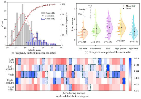
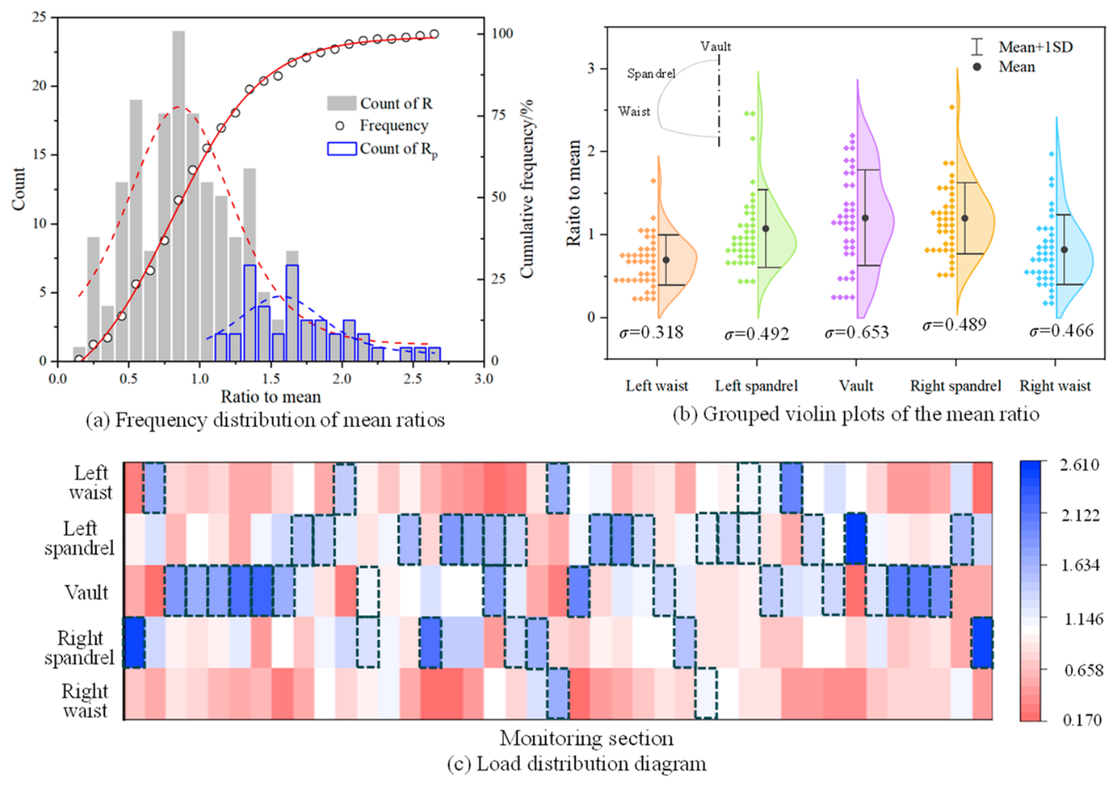
The mean ratio R is defined as the ratio of the pressure at a particular measurement location to the average pressure at the corresponding section. Furthermore, frequency statistics are performed on both the mean ratio R and the mean ratio of peak value Rp, as demonstrated in Figure 1a,b. A load distribution diagram is created to examine the distribution characteristics of local pressure, as depicted in Figure 1c.
Figure 1.
Load distribution of the surrounding rock.
- (1)
- Discrete Analysis: The mean ratio mainly ranges from 0.8 to 1.2, with 25 sections showing peak values above 1.5 (as shown in Figure 1a), accounting for 61.0% of the sections analyzed. This indicates a significant unevenness in the distribution of the surrounding rock load. Specifically, the mean ratio at the vault and spandrel locations is considerably higher than that at the arch waist position (refer to Figure 1b). The average load value at the vault is recorded at 430.0 kPa, which is significantly greater than the loads at other locations. Additionally, the standard deviation of the mean ratio at the vault is 0.653, highlighting its distinct characteristics.
- (2)
- Load Distribution Analysis: A review of the monitoring sections where load values exceed 30% of the mean value identifies 32 sections. Among these, 13 sections show loads exceeding 30% of the mean value solely at the vault, while 14 sections do so at the spandrel. Additionally, 5 sections demonstrate that loads at both the vault and spandrel surpass 30% of the mean value. This implies that localized additional loads may affect various points within the arches. The local pressure patterns, as depicted in Figure 1c, encompass the six non-uniform pressure distribution patterns: M1, local additional load at the vault; M2, at the spandrel; M3, at the waist; M4, combined vault–spandrel loading; M5, combined left–right spandrel loading; and M6, combined left–right waist loading.
Based on the statistical analysis, six typical patterns of non-uniform pressure distribution (M1 to M6 in Figure 1c) are identified. These patterns are reproduced by first applying a uniform surrounding rock pressure, then superimposing a localized additional static load at the corresponding location in the numerical simulations. Different cross-sections (e.g., circular or different invert shapes) may alter the load distribution patterns and the structural response. The data come from tunnels with different geology, size, and measurement methods. The resulting patterns are therefore used as a qualitative guide, not as a quantitative design rule.
3. Numerical Model for Local Pressure
To analyze the bearing performance of multiple arches under localized additional loads and ensure the stability of the support system, a numerical model of a three-frame combined arch was constructed. By conducting simulations on the mechanical performance of CFST arches and shaped steel arches under localized additional loads, a comparative analysis was carried out on the deformation characteristics and mechanical responses of the two types of arches. A combined arch is defined as a spatial tunnel support system composed of multiple arches connected by longitudinal connectors, which is not a single arch.
3.1. General Description
This study considered the Longding Tunnel in Shandong, China, with the maximum excavation section of 245.5 m2 as background. The surrounding rock mainly consists of grade IV and V limestone and marl. The rock mass is notably fragmented, featuring well-defined structural planes and poor interlayer cohesion, leading to a loose and fractured composition. The uniaxial compressive strength of the rock is between 15.5 MPa and 34.2 MPa.
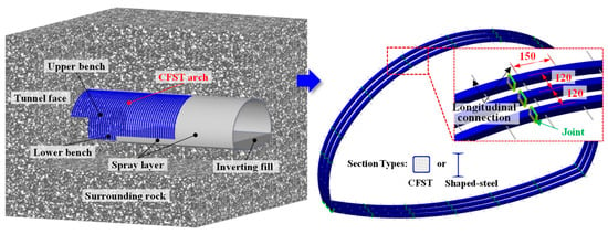
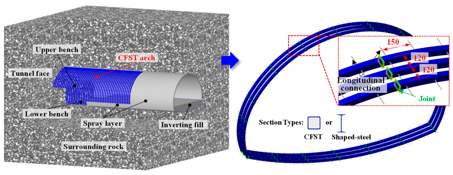
In the construction process involving three arches within a single cycle, three arches were chosen as the focus of the study, with a schematic representation of the CFST arch shown in Figure 2. The arch has a span of 21.40 m and a total height of 14.21 m. The current construction utilizes a shaped steel arch with a cross-section of I20a, with a spacing of 1.2 m. I20a refers to a Chinese standard I-section steel with a height of 200 mm, a flange width of 100 mm, a web thickness of 7 mm, a flange thickness of 11.4 mm, and a linear mass of 27.9 kg/m. The cross-sectional area of I20a is 35.5 cm2, and its strong-axis moment of inertia is 2369 cm4. The arches are longitudinally connected by Φ25 reinforcements with a ring spacing of 1.5 m. The chosen cross-section for the CFST combined arch is a square steel pipe with a width (B) of 150 mm and a wall thickness (t) of 8 mm. The cross-sectional area of the CFST section is 44.56 cm2, which is 1.25 times the cross-sectional area of the steel section; its theoretical linear mass is 34.96 kg/m, and its moment of inertia is 1530 cm4. The materials selected for the steel and core concrete are Q355 and C40, respectively, both of which are commonly used in construction.
Figure 2.
Schematic diagram of arch dimensions (unit: cm).
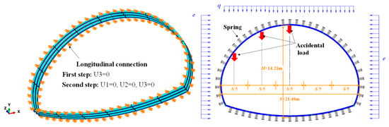
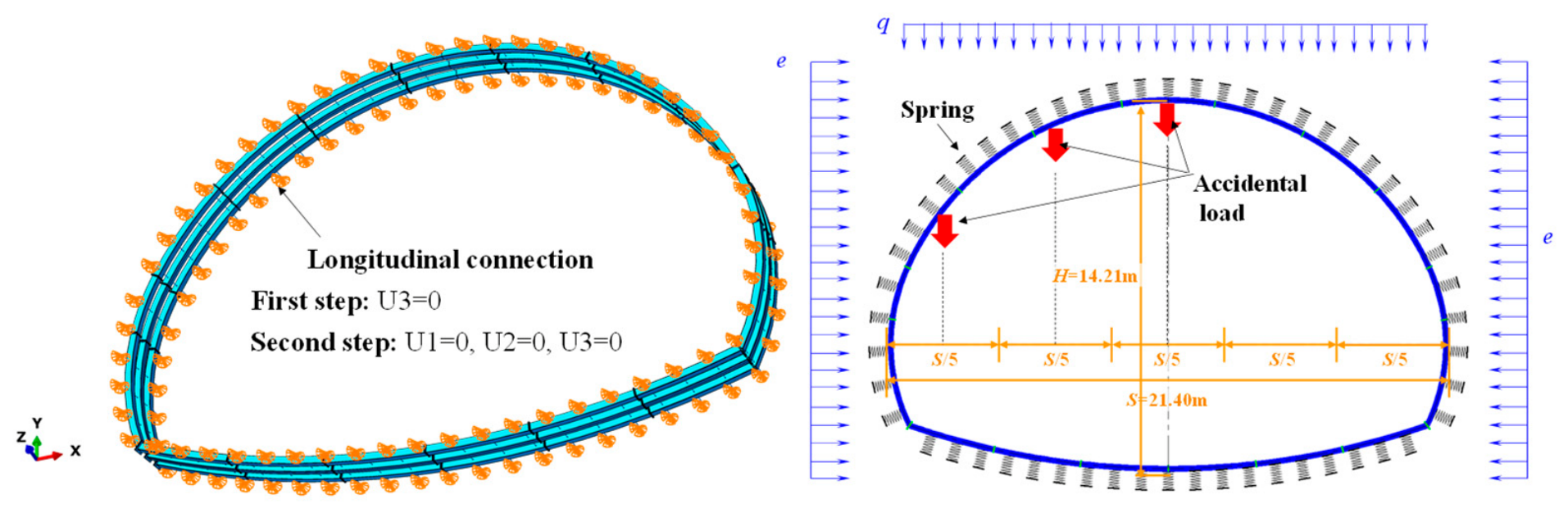
Figure 3 illustrates a schematic representation of the FEA modeling. The simulation utilized reduced integration 8-node linear brick elements (C3D8R) to represent the steel tube, core concrete, shaped steel, and the longitudinal connections between the arches. The steel tube is discretized with two layers of C3D8R elements through the wall thickness to analyze the local bending and buckling response. The arches are linked to the longitudinal connections using the Tie command, which also constrains the splicing between arch segments. For the steel–concrete interface simulation, a Coulomb friction model was employed, with surface-based interaction as the method. A sensitivity analysis of the steel–concrete interface friction coefficient was conducted. The allowable localized additional load changed by less than 5% across these values, confirming that the main conclusions are not critically dependent on the assumed friction coefficient. The friction coefficient for tangential behavior was set at 0.6 [35], while Hard Contact was applied for normal direction behavior. A mesh convergence study was performed. Considering computational accuracy and cost, an element size of 50 mm was selected for the parametric study.
Figure 3.
Schematic view of the FEA model.
It is important to acknowledge the simplifications inherent in this numerical approach. The surrounding rock mass is idealized as a series of independent Winkler springs, and the localized additional loads are applied directly as static forces. This modeling strategy neglects the complex continuum behavior, stress redistribution, and nonlinear ground–structure interaction that occur in reality. However, the primary objective of this study is to isolate and evaluate the fundamental structural response and ultimate capacity of the CFST arch system under a well-defined loading regime. The Winkler spring model is a simplified representation that neglects plastic stress redistribution, arching effects, and the explicit contribution of the shotcrete layer. It should therefore be regarded as a comparative structural model for evaluating the relative performance of CFST and shaped steel arches under defined loading conditions, rather than a model that provides a demonstrated conservative bound.
3.2. Constitutive Models for Concrete and Steel
ABAQUS is used to create a numerical model of the arch, implementing a five-stage model for the steel component within the concrete-filled steel tube structure, as referred to by Han et al. (2001) [36]. The relevant equation is as follows:
where, Es = 2.06 × 10⁵ MPa, ε1 = 0.8·fsy/Es, ε2 = 1.5·ε1, ε3 = 1.5·ε2, ε4 = 100·ε2, A = 2·fsy/(ε2 − ε1)2, B = 2·A·ε2, and C = 0.8·fsy + A·ε2 − B·ε1; fsy is the yield strength of the steel. The Poisson’s ratio of the steel μs is 0.3.
σ = Es·ε (ε ≤ ε1)
σ = −A·ε2 + B·ε + C (ε1 < ε ≤ ε2)
σ = fsy (ε2 < ε ≤ ε3)
σ = fsy·[1 + 0.6·(ε − ε3)/(ε4 − ε3)] (ε3 < ε ≤ ε4)
σ = 1.6·fsy (ε > ε4)
To simulate the plastic behavior of core concrete subjected to compression and bending forces, the stress–strain curve was derived from the research of Han et al. (2007) [35], and the Concrete Damage Plasticity (CDP) model was selected for this study. The CDP model parameters adopted in this study are summarized as follows: a dilation angle of 30°, an eccentricity of 0.1, a biaxial-to-uniaxial compressive strength ratio of 1.16, a shape factor of 0.667, and a viscosity parameter of 0.0001. The equivalent stress–strain model is presented as follows:
where x = ε/ε0, y = σ/σ0, σ0 = fc, ε0 = εc + 0.0008 ξ0.2, εc = (1300 + 12.5 fc) × 10−6, η = 1.6 + 1.5/x (square section), β0 = fc0.1/[1.2·(1 + ξ)0.5] (square section), and ξ = As·fsy/(Ac·fc). fc is the cylinder strength of the concrete. As and Ac are the cross-sectional areas of the steel tube and concrete, respectively. Elastic properties such as modulus Ec and Poisson’s ratio μc are set as 4730 fc0.5 and 0.2, respectively.
y = 2x − x2 (x ≤ 1)
y = x/[β0 (x − 1)η + x] (x > 1)
3.3. Boundary Conditions and Loading Procedure
The interaction between the surrounding rock and the arch is modeled using compression-only nonlinear springs (Winkler springs) distributed along the arch perimeter [37,38], as illustrated in Figure 3. The stiffness K of these springs is calculated based on the Winkler Elastic Foundation Beam Theory [39] as
where E = 2.2 GPa is the deformation modulus of the surrounding rock; Poisson’s rate of the surrounding rock μr = 0.36 is Poisson’s ratio; and R0 = S/2 is the equivalent radius with S being the arch span.
K = E/[(1 + μr) R0]
To evaluate the sensitivity of the numerical results to this assumed stiffness, a parametric study was conducted where the spring stiffness K was varied by ±50% of its nominal value. The results indicated that the predicted ultimate localized load capacity of the CFST arch changed by less than 8%. This relatively low sensitivity confirms that the main conclusions regarding the comparative performance of CFST versus shaped steel arches are robust and not critically dependent on the exact value of the spring stiffness.
The loading procedure consists of two sequential phases. In the first phase, the initial surrounding rock pressure, comprising vertical pressure q = 253.3 kPa and lateral pressures e1 = 76.0 kPa (at the spring line) and e2 = 145.7 kPa (at the invert), is applied uniformly to the arch in accordance with the Chinese highway tunnel design specification (JTG 3370.1-2018 [40]). During this phase, the longitudinal connections at both ends of the arch are restrained against translation. Following conventional limit state design practice in JTG 3370.1-2018, the localized load is treated as a static equivalent force superimposed on the uniform surrounding rock pressure. In the second phase, a monotonically increasing localized additional load is applied as a concentrated force at specified locations on the middle arch (see Table 2 for load patterns M1 to M6). The load is increased incrementally under displacement control until the arch reaches its deformation-controlled bearing capacity, defined as the point at which either the load–displacement curve attains a peak value or the maximum settlement exceeds the design reserved deformation of 120 mm in Clause 9.2.9 of JTG 3370.1-2018. The parametric study cases (C-F) vary the steel tube wall thickness, concrete core strength, arch spacing, and longitudinal connection spacing, while keeping all other parameters constant.
Table 2.
Load combination scheme.
In the numerical model, the shotcrete layer was not explicitly included as a composite element. The main purpose of this model is to isolate the structural response of the CFST combined arch itself and to compare it with the shaped steel combined arch under the same localized additional loading conditions. If the shotcrete layer were included, the additional composite action and load sharing would make it difficult to identify the intrinsic contribution of the arch itself to the overall bearing capacity.
4. Analysis of Load-Bearing Behavior Under Local Pressure
Using the aforementioned local pressure model, numerical simulations of CFST arches subjected to local pressure in large-section tunnels are conducted to examine their load-bearing behavior.
4.1. Bearing Performance Under Different Patterns of Localized Additional Load
4.1.1. Analysis of Deformation Characteristics
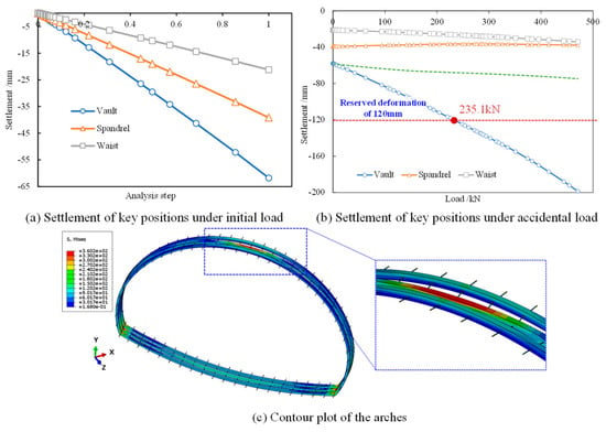
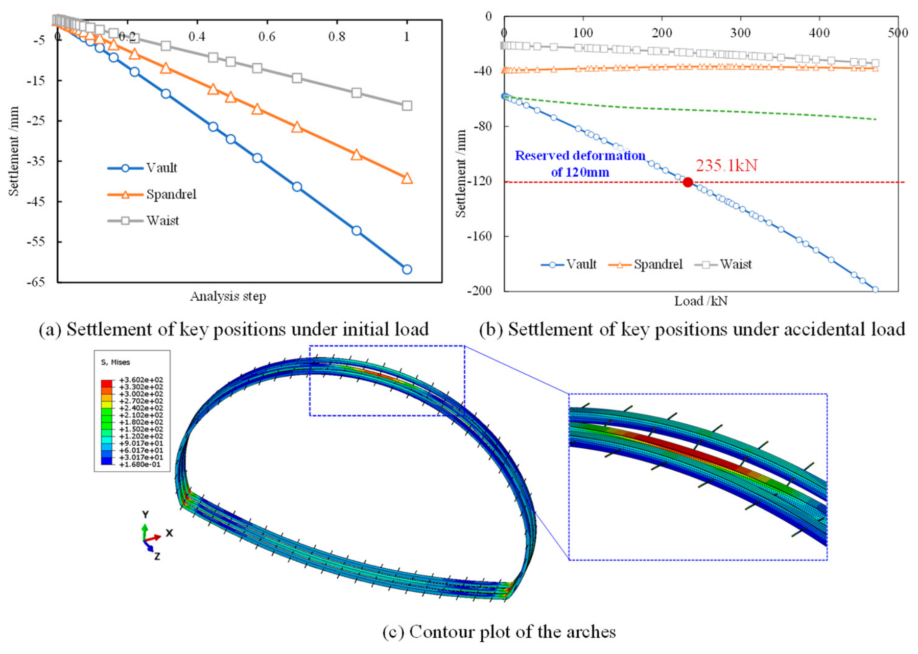
Taking the A1 scheme as an example, the stress behavior of the arches subjected to local pressure at the vault is analyzed. The settlement and contour plot at critical positions are shown in Figure 4. The green dashed line in the graph represents the vault settlement of the side arch. According to the requirements of the Design Specification for Highway Tunnels (JTG 3370.1-2018) for reserved deformation of large section tunnels, combined with engineering experience, the allowable localized additional load is defined as the local pressure at which the maximum settlement reaches 120 mm.
Figure 4.
Settlement of key positions and contour plot of the arches.
The analysis in Figure 4 shows the following:
- (1)
- Following the initial load application, the greatest settlement occurs at the vault, measuring 62.8 mm. The key positions at the shoulder and waist settle by 39.1 mm and 21.2 mm, respectively. All settlements remain within the design reserved deformation of 120 mm. The three arches experience simultaneous deformation, and the longitudinal connections do not face significant forces. It is calculated that, based on the ratio of the vertical load (253.3 kPa) to the deformation (62.8 mm) at the vault position, the deformation stiffness at the vault position is 4.03 kPa/mm.
- (2)
- When a localized additional load is applied, the settlement at the vault of the middle arch increases rapidly. The front and rear arches deform in response to the middle arch’s deformation due to the influence of the longitudinal connections, which experience considerable stress. The local load that corresponds to the magnitude of the superimposed localized load is 235.1 kN. The arch can withstand a volume of loose rock mass of 9.8 m3, based on a rock mass density of 24 kN/m3.
- (3)
- Under the localized additional load applied at the vault, the maximum von Mises stress is concentrated at the vault of the middle arch, reaching 360.2 MPa, which is higher than the yield strength of Q355 steel (355 MPa). This indicates that the steel tube in the vault is close to yielding and that local yielding may occur as the load increases. In contrast, the adjacent arches and the regions away from the vault exhibit much lower stress levels (roughly 100–200 MPa), as shown by the blue and green colors in the contour plot. This non-uniform stress distribution confirms that the middle arch carries the major share of the localized additional load, while the adjacent arches participate in load sharing through the longitudinal connections.
- (4)
- The stress gradient at the longitudinal connections is also visible in the enlarged view, indicating that connection forces are significant and that load transfer occurs between adjacent arches. Based on these results, the failure mechanism can be described as follows: the localized additional load first causes high compressive stress and local bending in the vault of the middle arch; with increasing load, the steel tube in the vault approaches yielding, and local buckling may occur, accompanied by crushing of the core concrete. The load is partially transferred to the adjacent arches through the longitudinal connections, which delays the overall failure of the combined arch system.
4.1.2. Comparison of Bearing Capacity
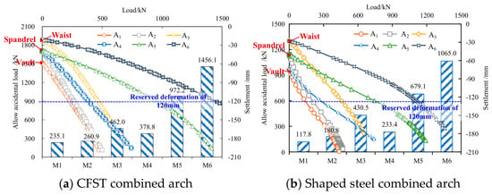
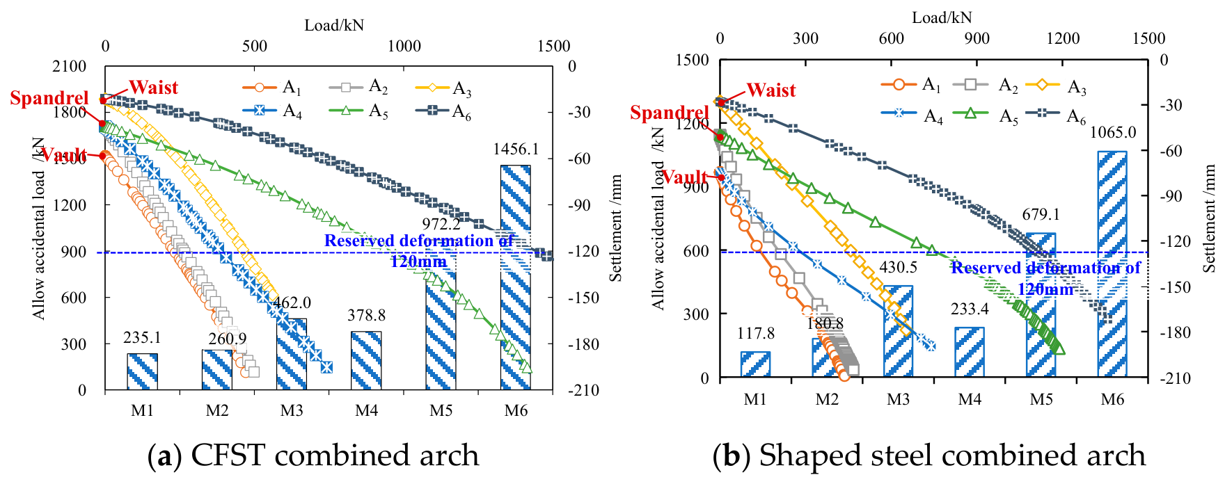
To evaluate how arches perform under localized additional loads, the load–deformation curves for key positions in each scheme were examined, as illustrated in Figure 5. The key positions of the arches related to Schemes M1~M6 represent the points of localized additional load application.
Figure 5.
Allowable localized additional load under different loading modes.
The analysis in Figure 5 shows the following:
The core concrete inside the steel tube restrains local buckling of the steel wall, while the steel tube confines the concrete, enhancing its compressive strength. This synergistic interaction significantly improves the overall stiffness and ductility of the CFST combined arch. Among the different loading schemes, Scheme M1 exhibits the lowest bearing capacity, while the CFST and shaped steel combined arches have bearing capacities of 235.1 kN and 117.8 kN, respectively. The CFST arch can withstand localized additional loads that are 99.6% greater than those of the shaped steel arch. After the initial loading phase, the initial vault settlements for the CFST and shaped steel arches in Scheme M1 were recorded at 62.8 mm and 74.5 mm, respectively. The CFST arch’s greater stiffness resulted in a 15.7% reduction in initial vault settlement compared to the shaped steel arch.
4.2. Influence of the Initial Uniform Pressure Level on the Resistance
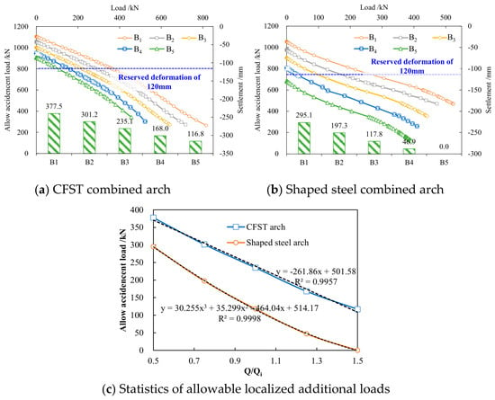
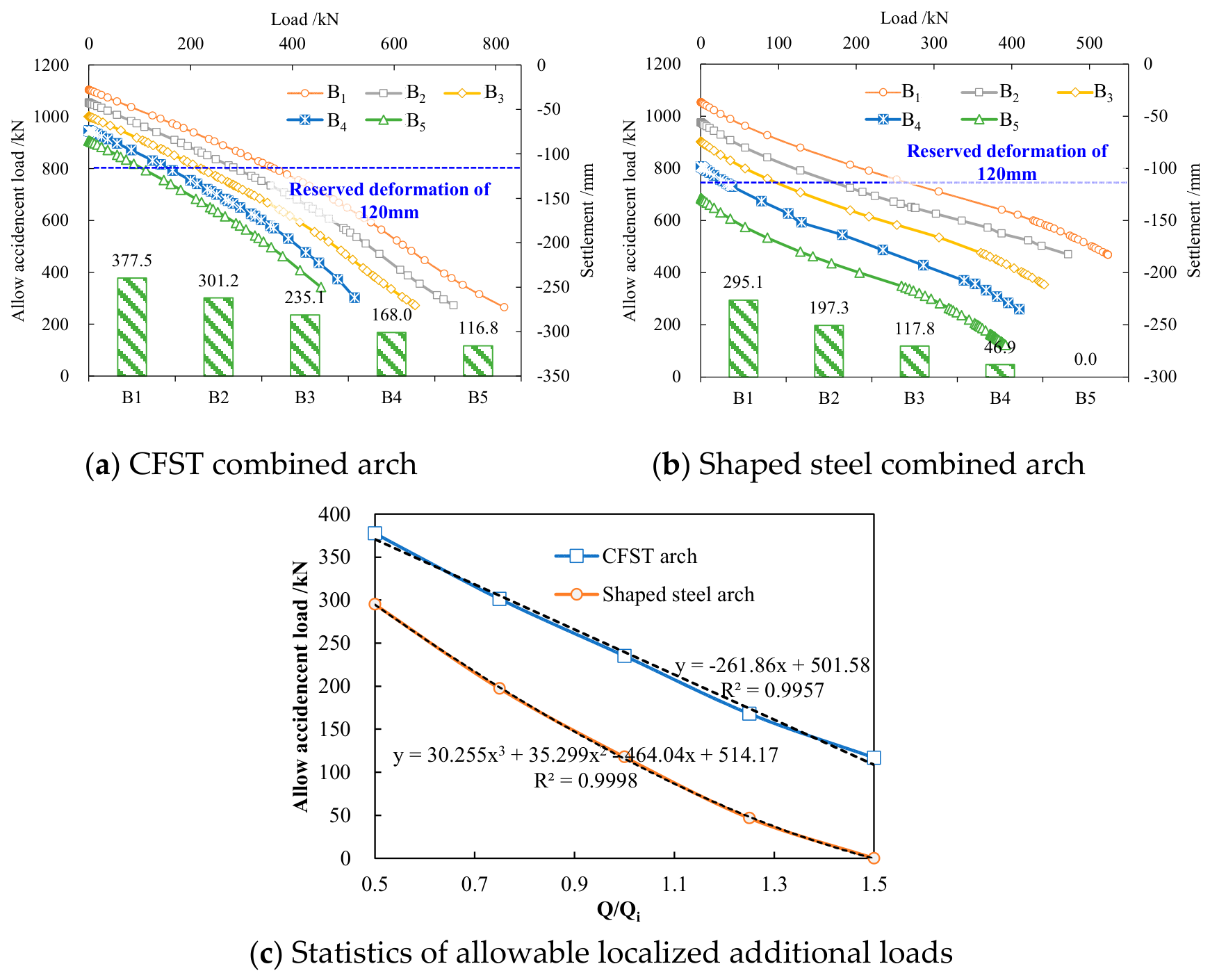
To evaluate the bearing capacity of the arches in response to localized additional loads under various initial load scenarios, the settlement–load curves of each scheme were examined, as illustrated in Figure 6. A statistical analysis was conducted to determine the permissible localized additional load that the CFST and shaped steel arches can support under different initial loads. The coefficient α is introduced as the amplification factor for the initial load, and the relationships between this amplification factor and the allowable localized additional load were graphed.
Figure 6.
Statistics of allowable localized additional loads under different initial loads.
The analysis in Figure 6 shows the following:
The allowable localized additional load that the CFST and shaped steel combined arches can support diminishes progressively as the initial load increases. In the CFST arch simulation, there is a linear correlation between the allowable localized additional load and the initial load, whereas in the shaped steel combined arch simulation, this relationship is distinctly nonlinear. The CFST combined arch exhibits a greater capacity to withstand localized additional loads compared to shaped steel arches when both are subjected to the same allowable localized additional load. This synergistic interaction of CFST arches maintains a stable stiffness and ductility even under increasing initial load. In contrast, shaped steel arches rely solely on the steel section, which is more susceptible to local buckling and plastic hinge formation, leading to a nonlinear degradation of capacity.
Specifically, the allowable localized additional load for the CFST combined arch at a magnification factor of 1.25 is roughly equivalent to that of the shaped steel combined arch at a magnification factor of 0.75. Additionally, CFST arches demonstrate a more consistent bearing capacity under localized additional loads. When the amplification factor is 1.5, the settlement at the arch position has exceeded the reserved deformation, which does not meet the design requirements.
4.3. Parametric Study on the Resistance to Localized Additional Load
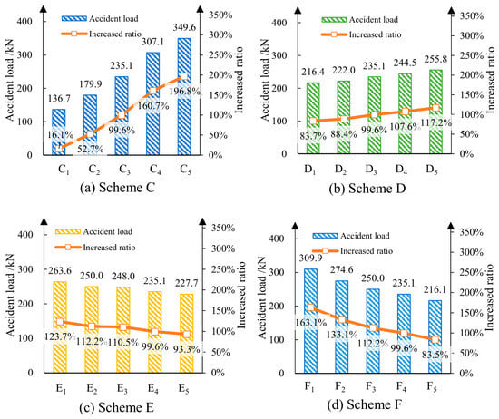
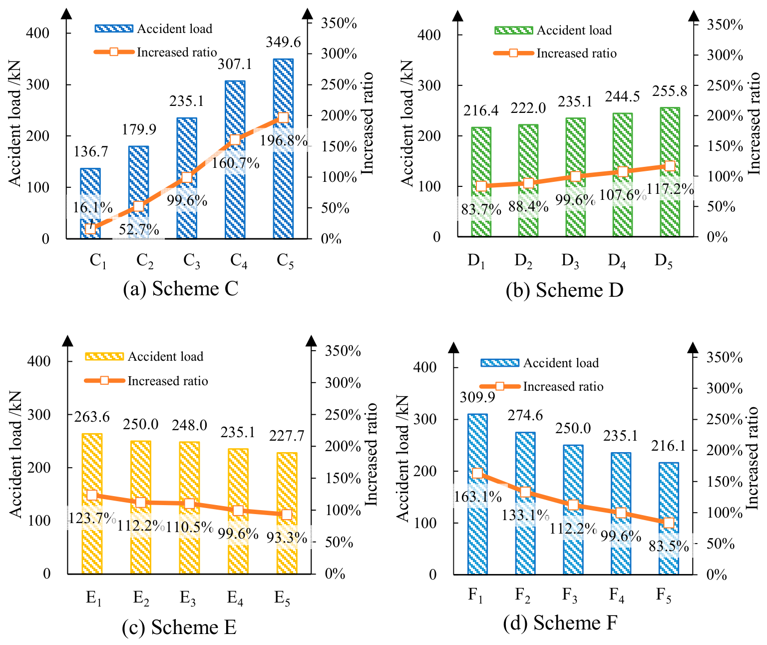
The load-bearing behavior of CFST arches under various design parameters was obtained through numerical simulations. In comparison with shaped steel arches, the load-transfer mechanisms of different parameters under localized additional load of CFST arches were analyzed. The bearing capacity of CFST arches derived from numerical calculations is shown in Figure 7, with the corresponding percentage increase, defined as the percentage increase in the bearing capacity of CFST arches relative to that of shaped steel arches.
Figure 7.
Bearing capacity of CFST arches under localized additional load.
The analysis in Figure 7 shows the following:
- (1)
- Steel tube wall thickness (C1–C5): Bearing capacity increases significantly with wall thickness. For example, from 6 mm to 10 mm, the capacity rises from 136.7 kN to 349.6 kN, with an increased ratio from 16.1% to 196.8%.
- (2)
- Concrete strength (D1–D5): Higher concrete strength enhances bearing capacity, though the effect is less pronounced than wall thickness. C40 to C60 increases capacity by about 8.8%.
- (3)
- Arch spacing (E1–E5): Closer arch spacing improves bearing capacity. At 0.6 m spacing, capacity reaches 263.6 kN, 12.1% higher than at 1.2 m.
- (4)
- Longitudinal connection spacing (F1–F5): Reduced spacing enhances load distribution and bearing capacity. At 0.75 m spacing, capacity is 309.9 kN, 31.8% higher than at 1.5 m. While closer spacing improves overall load distribution, it may also introduce local stress concentrations and potential concrete crushing at the connection points.
The most influential parameter is steel tube wall thickness, followed by longitudinal connection spacing. For optimal performance in large-section tunnels under localized additional loads, it is recommended to use steel tube wall thickness ≥ 8 mm, concrete strength ≥ C40, arch spacing ≤ 1.0 m, and longitudinal connection spacing ≤ 1.0 m under surrounding rock grades IV and V at the Longding Tunnel.
4.4. Engineering Suggestions and Field Application
4.4.1. Engineering Suggestions
Based on the results of the FEA simulation, the following engineering suggestions are proposed:
- (1)
- It is advisable to replace shaped steel arches with CFST arches in large-section tunnels traversing jointed and fractured rock masses to ensure construction safety. Based on the parametric study, the use of CFST arches is recommended, particularly in sections identified as high-risk due to potential localized overloading.
- (2)
- Based on the parametric study in Section 4.3, vault settlement and spandrel pressure difference are identified as key monitoring indicators for detecting local overloading. To ensure construction safety, the following monitoring thresholds are proposed: (a) if the daily vault settlement rate exceeds 5 mm/d for three consecutive days according to the Chinese highway tunnel design specification, or (b) if the difference between left and right spandrel pressures exceeds 35% of their average value, an early warning should be issued and reinforcement measures implemented immediately.
4.4.2. Field Application
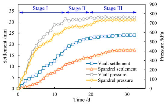
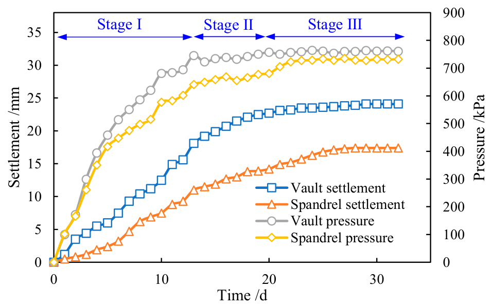
In the field application, the surrounding rock pressure is naturally non-uniform and random, and it is difficult to control or reproduce a prescribed localized overload condition. Therefore, field monitoring is used to verify the field application of the CFST arch and to check the reasonableness of the numerical model. The continuous monitoring of field arch pressure and tunnel deformation was carried out, as shown in Figure 8. The key positions, such as the vault, the spandrel, and the waist, were selected for pressure monitoring on the arch. The designed CFST arch is a square steel pipe with a width (B) of 150 mm and a wall thickness (t) of 8 mm, with a spacing of 1.2 m and a ring spacing of 1.5 m. The materials selected for the steel and core concrete are Q355 and C40.
Figure 8.
Field application in Longding Tunnel.
As illustrated in Figure 8, the deformation of the on-site arch support underwent three distinct phases: a rapid growth phase, a slow growth phase, and a basically stable phase. The maximum vault settlement and pressure were 23.3 mm and 764.3 kPa, respectively. The pressure exerted on the vault is jointly borne by the arch support and the shotcrete layer. The thickness of the concrete spray layer is 240 mm. Based on calculations using the flexural stiffness of the two components, the pressure shares undertaken by the arch support and the shotcrete layer are 79.6 kPa and 684.7 kPa, respectively. From this, the deformation stiffness at the vault position of the arch support is calculated as 3.41 kPa/mm, derived from the ratio of the maximum vault settlement (23.3 mm) to the corresponding undertaken pressure (79.6 kPa). The discrepancy between this value and the vault deformation stiffness obtained from numerical simulation is 18.3%. This discrepancy, being within 20%, provides an overall consistency check of the numerical simulation model.
To provide a more direct validation, a simplified numerical model of the Longding Tunnel section was developed. The model explicitly included the CFST arch, the 240 mm thick shotcrete layer, and the surrounding rock, simulated using the same Winkler spring approach. The in situ stress state and excavation sequence were not modeled; instead, the measured final pressure on the support system was applied as the load. While this simplified validation is not exhaustive, it provides a reasonable check on the model’s ability to capture the overall structural response of the support system under the given loads. Further independent validation using different loading cases is needed in future work.
5. Conclusions
- (1)
- The combined arches exhibit their lowest bearing capacity when subjected to local loading at the vault. Specifically, the bearing capacities for CFST and shaped steel combined arches are 235.1 kN and 117.8 kN, respectively. The CFST combined arches demonstrate greater stiffness, resulting in a 15.7% reduction in initial vault settlement compared to the shaped steel combined arches.
- (2)
- In the CFST arch simulation, there is a linear correlation between the allowable localized additional load and the initial load, whereas in the shaped steel arch simulation, this relationship is distinctly nonlinear. This synergistic interaction of CFST arches maintains a stable stiffness and ductility even under increasing initial load. In contrast, shaped steel arches rely solely on the steel section, which is more susceptible to local buckling and plastic hinge formation, leading to a nonlinear degradation of capacity. The allowable localized additional load for the CFST arch at an initial load magnification factor of 1.25 is approximately equivalent to that of the shaped steel arch at a magnification factor of 0.75.
- (3)
- Within the limitations of the simplified Winkler-spring model, a mechanical model for arches in a large-section tunnel was developed. The analysis focused on the various stress stages experienced by the tunnel arches under localized additional load, leading to the formulation of relevant engineering suggestions based on the comprehensive findings; further validation is needed before final design.
Author Contributions
Z.X.: conceptualization, methodology, software, validation, formal analysis, investigation, data curation, writing—original draft preparation, writing—review and editing, visualization, project administration. J.D.: methodology, validation, investigation, writing—review and editing. B.W.: software, formal analysis, data curation, visualization. Z.J.: conceptualization, validation, resources, supervision, project administration, funding acquisition, writing—review and editing. All authors have read and agreed to the published version of the manuscript.
Funding
This research was funded by the National Natural Science Foundation of China (grant number U2468217, 52508456), the Fundamental Research Funds for the Central Universities (grant number 2682025CX045), the China Postdoctoral Science Foundation (grant number 2025M773282), and the Major R&D project of Zhejiang Provincial Department of Transportation (grant number 2025ZD001).
Institutional Review Board Statement
Not applicable.
Informed Consent Statement
Informed consent was obtained from all subjects involved in the study.
Data Availability Statement
All data, models, or code that support the findings of this study are available from the corresponding author upon reasonable request.
Conflicts of Interest
The authors declare no conflicts of interest.
References
- Qian, Q.; Lin, P. Safety risk management of underground engineering in China: Progress, challenges and strategies. J. Rock Mech. Geotech. Eng. 2016, 8, 423–442. [Google Scholar] [CrossRef] [Scilit]
- He, M.; Sousa, R.L.E.; Müller, A.; Vargas, E.; Sousa, L.R.E.; Chen, X. Analysis of excessive deformations in tunnels for safety evaluation. Tunn. Undergr. Space Technol. 2014, 45, 190–202. [Google Scholar] [CrossRef] [Scilit]
- Wang, B.; Yu, W.; Chen, Z. Effect of anchor plate on the mechanical behavior of prestressed rock bolt used in squeezing large deformation tunnel. Acta Geotech. 2022, 17, 3591–3611. [Google Scholar] [CrossRef] [Scilit]
- Chen, Y.; Zhang, X.; Qiao, X. Experimental study of the reinforcement mechanism for the tunnel support structure in weak rock masses. Int. J. Geomech. 2023, 23, 04023173. [Google Scholar] [CrossRef] [Scilit]
- Wang, Q.; Qin, Q.; Jiang, B.; Xu, S.; Zeng, Z.; Luan, Y.; Liu, B.; Zhang, H. Mechanized construction of fabricated arches for large-diameter tunnels. Autom. Constr. 2021, 124, 103583. [Google Scholar] [CrossRef] [Scilit]
- Jiang, B.; Xin, Z.; Zhang, X.; Deng, Y.; Wang, M.; Li, S.; Ren, W. Mechanical properties and influence mechanism of confined concrete arches in high-stress tunnels. Int. J. Min. Sci. Technol. 2023, 33, 829–841. [Google Scholar] [CrossRef] [Scilit]
- Fu, J.; Xie, J.; Wang, S.; Yang, J.; Yang, F.; Pu, H. Cracking performance of an operational tunnel lining due to local construction defects. Int. J. Geomech. 2019, 19, 04019019. [Google Scholar] [CrossRef] [Scilit]
- Yu, W.; Wang, B.; Zi, X.; Guo, X.; Wang, Z. Effect of prestressed anchorage system on mechanical behavior of squeezed soft rock in large-deformation tunnel. Tunn. Undergr. Space Technol. 2022, 131, 104782. [Google Scholar] [CrossRef] [Scilit]
- Jin, C.; Sun, C.; Lan, S.; Zhang, J. Progressive collapse mechanism analysis of tunnel roof with weak surrounding rock considering seepage effect. Int. J. Geomech. 2025, 25, 04025170. [Google Scholar] [CrossRef] [Scilit]
- Xin, Z.; Jiang, B.; Wang, Q.; Wang, M.; Zhang, C.; Wei, H.; Li, D.; Sun, L. Bearing behaviour and failure mechanism of spatial coupling arches in large-section tunnel. Structures 2024, 60, 105937. [Google Scholar] [CrossRef] [Scilit]
- Wang, Q.; Jiang, B.; Pan, R.; Li, S.; He, M.; Sun, H.; Qin, Q.; Yu, H.; Luan, Y. Failure mechanism of surrounding rock with high stress and confined concrete support system. Int. J. Rock Mech. Min. Sci. 2018, 102, 89–100. [Google Scholar] [CrossRef] [Scilit]
- Li, S.; Wang, Q.; Jiang, B.; He, M.; Sun, H.; Shao, X.; Wang, C.; Qin, Q.; Yu, H. Modeling and experimental study of mechanical properties of confined concrete arch in complicated deep underground engineering. Int. J. Geomech. 2016, 17, 04016137. [Google Scholar] [CrossRef] [Scilit]
- Wang, Q.; Pan, R.; Jiang, B.; Li, S.; He, M.; Sun, H.; Wang, L.; Qin, Q.; Yu, H.; Luan, Y. Study on failure mechanism of roadway with soft rock in deep coal mine and confined concrete support system. Eng. Fail. Anal. 2017, 81, 155–177. [Google Scholar] [CrossRef] [Scilit]
- Huang, W.; Yuan, Q.; Tan, Y.; Wang, J.; Liu, G.; Qu, G.; Li, C. An innovative support technology employing a concrete-filled steel tubular structure for a 1000-m-deep roadway in a high in situ stress field. Tunn. Undergr. Space Technol. 2017, 73, 26–36. [Google Scholar] [CrossRef] [Scilit]
- Wu, H.; Fan, F.; Yang, X.; Wang, Z.; Lai, J.; Xie, Y. Large deformation characteristics and treatment effect for deep bias tunnel in broken phyllite: A case study. Eng. Fail. Anal. 2022, 135, 106045. [Google Scholar] [CrossRef] [Scilit]
- Zhou, Y.; Yang, W.; Zhao, L.; You, Z.; Tian, H.; Zhang, L.; Zhu, Z. Research on reasonable reserved deformation and height-span ratio of a large deformation tunnel section in high geo-stress soft rock near a fault zone: A case study. Bull. Eng. Geol. Environ. 2023, 82, 378. [Google Scholar] [CrossRef] [Scilit]
- Yang, Y.; Tan, Z.; Xue, J.; Li, S. High-strength lattice girders supporting performance of highway tunnel with soft broken surrounding rock. China J. Highw. Transp. 2020, 33, 125–134. (In Chinese) [Google Scholar] [CrossRef]
- Luo, Y.; Chen, J.; Shi, Z.; Li, J.; Liu, W. Mechanical characteristics of primary support of large span loess highway tunnel: A case study in Shaanxi Province, Loess Plateau, NW China primary. Tunn. Undergr. Space Technol. 2020, 104, 103532. [Google Scholar] [CrossRef] [Scilit]
- Zhao, J.; Tan, Z.; Liu, X.; Zhang, B.; Xie, W.; Ma, Q. Large deformation characteristics and mechanisms of deep-buried foliated basalt tunnel: A case study of the Haba Snow Mountain Tunnel. Rock Mech. Rock Eng. 2024, 58, 3523–3544. [Google Scholar] [CrossRef] [Scilit]
- Chen, J.; Jiang, J.; Luo, Y.; Wang, M. Mechanics characteristic analysis of support structure of loess tunnel entrance. China J. Highw. Transp. 2008, 21, 75–80. (In Chinese) [Google Scholar] [CrossRef]
- Chen, Q.; Zeng, A.; Luo, P.; An, Y.; Hu, W.; Luo, X. Study on mechanical characteristics of primary support structure in large deformation section of carbonaceous slate in Yuanbaoshan tunnel. Chin. J. Appl. Mech. 2020, 37, 810–817. (In Chinese) [Google Scholar]
- He, B.; Zhu, Y.; Sun, M.; Zhang, Z. Experimental study of mechanical characteristics of support system for tunnel in Gypsum Breccia Stratum. Chin. J. Rock Mech. Eng. 2012, 31, 945–952. (In Chinese) [Google Scholar]
- Liu, D.; Zhang, D.; Fang, Q.; Sun, Z.; Luo, J.; Li, A. Field monitoring of the deformation and internal forces of the surrounding rock and support structures in the construction of a Super-Span High-Speed Railway Tunnel—A case study. Appl. Sci. 2020, 10, 5182. [Google Scholar] [CrossRef] [Scilit]
- Yue, J.; Liang, Q.; Zhang, T.; Fan, C. Research on mechanical response and time-space distribution of supporting structure of deep-buried tunnel in naturally water-rich loess. Tunn. Undergr. Space Technol. 2024, 147, 105688. [Google Scholar] [CrossRef] [Scilit]
- Shen, Y.; Gao, B. Site monitoring and analytical research on mechanical characteristics under construction partial press in double-arch tunnel. Rock Soil Mech. 2006, 27, 2061–2065. (In Chinese) [Google Scholar] [CrossRef]
- Sun, Z.; Zhang, D.; Liu, D.; Tai, Q.; Hou, Y. Insights into the ground response characteristics of shallow tunnels with large cross-section using different pre-supports. Int. J. Rock Mech. Min. Sci. 2024, 175, 105663. [Google Scholar] [CrossRef] [Scilit]
- Sun, Z.; Zhang, D.; Li, M.; Guo, F. Large deformation characteristics and the countermeasures of a deep-buried tunnel in layered shale under groundwater. Tunn. Undergr. Space Technol. 2023, 144, 105575. [Google Scholar] [CrossRef] [Scilit]
- Chen, C.; Lai, H.; Liu, Y. Study on failure mechanism and treatment measures of inverted arch under asymmetric immersion of loess tunnel basement. Eng. Fail. Anal. 2024, 163, 108494. [Google Scholar] [CrossRef] [Scilit]
- Chen, Z.; Yao, Y.; Wang, B.; Xie, Q.; Zhou, Z.; Jiang, C. Stability analysis and failure mechanism of multiple parallel soft-rock tunnels considering the random distribution of rockmass joints. Eng. Fail. Anal. 2024, 159, 108150. [Google Scholar] [CrossRef] [Scilit]
- Zhang, J.; Yan, Z.; Ma, K.; Feng, J.; Zhou, P. Initial support failure mechanisms and control techniques for tunnel in silty clay stratum. KSCE J. Civ. Eng. 2024, 28, 3558–3573. [Google Scholar] [CrossRef] [Scilit]
- Tu, H.; Zhou, H.; Qiao, C.; Gao, Y. Excavation and kinematic analysis of a shallow large-span tunnel in an up-soft/low-hard rock stratum. Tunn. Undergr. Space Technol. 2019, 97, 103245. [Google Scholar] [CrossRef] [Scilit]
- Chen, Z.; Yan, Q.; Zhou, Z.; He, C.; Li, T.; Bao, Y. Stability analysis and deformation control of tunnel with extremely weak surrounding rocks caused by strike-slip fault activity. Rock Mech. Rock Eng. 2023, 56, 8543–8569. [Google Scholar] [CrossRef] [Scilit]
- Wang, Z.; Cai, Y.; Fang, Y.; Lai, J.; Han, H.; Liu, J.; Lei, H.; Kong, X. Local buckling characteristic of hollow π-type steel-concrete composite support in hilly-gully region of loess tunnel. Eng. Fail. Anal. 2022, 143, 106828. [Google Scholar] [CrossRef] [Scilit]
- Zhao, Y.; He, H.; Li, P. Key techniques for the construction of High-Speed Railway Large-Section Loess tunnels. Engineering 2018, 4, 254–259. [Google Scholar] [CrossRef] [Scilit]
- Han, L.; Yao, G.; Tao, Z. Performance of concrete-filled thin-walled steel tubes under pure torsion. Thin-Walled Struct. 2007, 45, 24–36. [Google Scholar] [CrossRef] [Scilit]
- Han, L.; Zhao, X.; Tao, Z. Tests and mechanics model for concrete-filled SHS stub columns, columns and beam-columns. Steel Compos. Struct. 2001, 1, 51–74. [Google Scholar] [CrossRef]
- Zhao, H.; Liu, X.; Bao, Y.; Yuan, Y.; Bai, Y. Simplified nonlinear simulation of shield tunnel lining reinforced by epoxy bonded steel plates. Tunn. Undergr. Space Technol. 2015, 51, 362–371. [Google Scholar] [CrossRef] [Scilit]
- He, H.; Tang, X.; Lin, S.; Yan, Z.; Li, D. Field experiments and numerical simulations for two types of steel tube lining structures under high internal pressure. Tunn. Undergr. Space Technol. 2021, 120, 104272. [Google Scholar] [CrossRef] [Scilit]
- Tu, Z.; Sun, J.; Cai, X. Researches on calculation methods of rock resistant coefficients of submarine tunnels. Chin. J. Geotech. Eng. 2006, 28, 1002–1007. (In Chinese) [Google Scholar] [CrossRef]
- JTG 3370.1-2018; Highway Tunnel Design Specification. China Communications Press Co., Ltd.: Beijing, China, 2018; Volume 1.

Disclaimer/Publisher’s Note: The statements, opinions and data contained in all publications are solely those of the individual author(s) and contributor(s) and not of MDPI and/or the editor(s). MDPI and/or the editor(s) disclaim responsibility for any injury to people or property resulting from any ideas, methods, instructions or products referred to in the content. |
© 2026 by the authors. Licensee MDPI, Basel, Switzerland. This article is an open access article distributed under the terms and conditions of the Creative Commons Attribution (CC BY) license.