


Abstract
This paper deals with a magnetorheological damper-based vibration reduction system (MRD-VRS) with an energy harvesting ability. Together with the vibration-isolated object, the MRD-VRS constitutes a mechanical system with one degree of freedom (1DOF), which is set in motion by kinematic excitation. The authors propose improving the system performance by utilising voltage resonance in its electrical circuit. The originality of the concept involves placing an RLC two-port network between the harvester coil (the electrical energy source) and the MR damper coil (the receiver). This increases the current amplitude selectively, resulting in an increase in the force produced by the MR damper neighbouring the 1DOF mechanical system’s resonance frequency. At the same time, this current is reduced at frequencies significantly higher than the resonance frequency. The intention behind shaping the current in the MR damper coil is to improve the MRD-VRS’s performance, so that it can reduce the vibration-isolated object’s displacement amplitude more effectively across the entire frequency range. The aim of the study is to determine the RLC two-port network parameters that maximise the MR damper coil current at the mechanical resonance frequency of the 1DOF system by exploiting voltage resonance. It should be noted that the resonant frequency of the RLC two-port network differs from the frequency at which the maximum current in the MR damper coil is achieved, since the electrical circuit is branched. The paper considers a mathematical model, the results of numerical simulations and the validation of both the electrical circuit comprising an RLC two-port network and the MRD-VRS under consideration. Analysis of the numerical results determined the resonant frequency and quality factor of the RLC two-port network, achieving the greatest improvement in vibration damping efficiency across the entire range of excitation frequencies.
1. Introduction
The aim of reducing the impact of mechanical vibrations on civil engineering structures, machinery and vehicles is to protect these objects from damage and failure. Effective vibration-reduction systems are essential wherever the human body is exposed to vibrations. Such systems often incorporate magnetorheological (MR) dampers, which are mechanical components whose damping force is controlled by an electric current [1]. MR dampers exhibit nonlinear hysteretic behaviour resulting from the magnetic properties of the control circuit [2] and the properties of the MR fluid itself [3]. Applications of MR dampers include civil engineering [4], the automotive industry [5], aerospace [6], biomedical engineering [7] and robotics [8]. In an MR damper-based vibration reduction system (MRD-VRS), the kinetic energy of the vibrating structure is converted into thermal energy, which is irretrievably lost. Conventional MRD-VRS systems require a control system powered by an external electrical energy source to function correctly. However, part of the kinetic energy of the vibrations can be recovered by converting it into electrical energy using energy harvesters [9,10,11,12,13]. Energy conversion methods include [13]: the electromagnetic method, the piezoelectric method, the magnetostrictive method and the electrostatic method. The choice of conversion method depends on the amplitude and frequency of the vibrations, as well as the power required to supply the load. The piezoelectric method is most commonly used to power energy-efficient sensors with a power consumption of up to several tens of milliwatts, using energy recovered from low-amplitude, high-frequency vibrations. Electromagnetic harvesters are mainly used to harvest higher-amplitude vibrations at low (up to 200 Hz) or very low (up to 10 Hz) frequencies [12]. Powering MR dampers requires higher power, which can only be supplied by electromagnetic harvesters. The construction of electromagnetic harvesters is based on the principle of the reciprocating motion of a magnet assembly (the source of the magnetic field) relative to the coil, which induces an electromotive force in accordance with Faraday’s law [14,15,16,17]. Mechanisms that convert reciprocating motion into rotary motion are also employed, enabling the use of conventional electric generators [18,19,20].
The concept of a vibration reduction system incorporating an MR damper powered by energy harvested from vibrations was first presented in a paper by Scuggs and Linder [21]. Since then, self-powered MRD-VRS systems have been used to protect multi-storey buildings [22,23], bridge structures [24], and steel cables in suspension bridges [25]. The development of these systems has led to attempts to integrate a harvester and an MR damper into a single unit, as described in the works [26,27,28,29,30,31]. More generally, the possibility of achieving simultaneous vibration reduction and energy harvesting has been investigated in vibration absorber/harvester systems [32]. Specifically, the use of a semi-active suspension incorporating an MR damper has been demonstrated to reduction vibrations while recovering energy from absorber motion [33]. Energy efficiency is also an important consideration in actively controlled vibration-reduction systems. For example, in [34], authors investigated an active vibration reduction system employing a tuned mass damper controlled by a modified sliding-mode algorithm, considering both vibration attenuation and electrical energy consumption.
The authors’ previous research aimed to improve the vibration damping efficiency of a vibration-isolated object using an MRD-VRS with energy harvesting ability, described in more detail in [35]. This is a single-degree-of-freedom (1DOF) system driven into motion by kinematic excitation. An energy balance analysis of this system clearly demonstrated that the amount of energy recovered from mechanical vibrations is sufficient to power the MR damper’s control coil effectively [36]. However, when the MR damper is powered directly from the harvester, the main problem is an increase in the vibration amplitude of the vibration-isolated object at frequencies higher than the resonance frequency of the 1DOF system. To address this shortcoming of the MRD-VRS, the authors incorporated an electronic control circuit comprising an energy-efficient microcontroller between the harvester coil and the MR damper [37]. This solution requires high-efficiency voltage rectification and stabilisation to ensure the microcontroller can correctly execute the MR damper current control algorithm. The main drawbacks are the significant complexity of the electrical circuit and the fact that the control system fails to operate at frequencies lower than the resonance frequency due to insufficient voltage from the harvester, which increases the amplitude of the object’s vibrations. Another solution proposed by the authors involves using bipolar coupling capacitors [38]. However, this solution has the drawback of excessive current draw from the harvester. Over time, this may damage the harvester’s coil. The approaches described above involve different trade-offs: the microcontroller-based solution enables active current control but requires additional power-conditioning and control circuitry, whereas the capacitor-based solution is passive but may impose excessive electrical loading on the harvester. Consequently, an electrical circuit containing an RLC two-port network was constructed to selectively increase the voltage across the MR damper coil. The results of experimental investigations of this circuit are presented in [39] and were used to verify the results of the numerical simulations presented in the current paper. Reference [40] demonstrated that an RLC circuit connected to a harvester coil in a 1DOF mechanical system corresponds to the dynamic behaviour of a system with an attached tuned mass damper (TMD). While these studies investigated the electrical behaviour of the RLC two-port network and its effect on the dynamics of a 1DOF mechanical system, the present paper focuses on how the RLC two-port network parameters affect the current supplied to the MR damper and the vibration reduction performance of the coupled electromechanical system, with particular attention to the frequency range around the mechanical resonance.
The aim of this paper is to utilise the phenomenon of voltage resonance to improve the efficiency of a vibration reduction system featuring an MR damper with an energy harvesting ability. To achieve this, the proposed modification to the electrical circuit involves incorporating an RLC two-port network between the harvester coil and the MR damper. The key issue is selecting the appropriate R, L, and C parameters to selectively increase the current supplied to the MR damper coil near the mechanical system’s resonance frequency. The numerical simulation results presented in this paper, covering both the electrical circuit itself and the vibration reduction system in which it is incorporated, demonstrate the influence of the RLC two-port network parameters on the effectiveness of vibration damping. The electrical circuit and the MRD-VRS without the RLC two-port network are validated separately against experimental results.
The 1DOF mechanical system considered in this study is intended as a reference model for investigating the potential of voltage resonance in a passive RLC network to improve the performance of an energy-harvesting vibration reduction system equipped with an MR damper. The model is not intended to represent a specific engineering structure or operational load. Potential applications of the proposed concept include vehicle suspension systems and vibration isolation systems for industrial machinery and equipment. Extension to such applications requires consideration of their specific dynamic characteristics, boundary conditions, excitation spectra, and, where necessary, higher-order vibration modes. The generality of the proposed approach should therefore be understood in terms of the electrical concept, rather than as a direct validation for arbitrary mechanical structures.
The paper is structured as follows. Section 1 refers to the results of scientific reports in the scope of the system concerned in the study and recalls the former authors’ achievement in this regard. Section 2 presents the considered MR damper-based vibration reduction system and the problem description and outlines the applied approach. Section 3 present electrical circuit of the MRD-VRS with emphasis on mathematical modelling, numerical simulation and validation. Section 4 presents mathematical modelling and validation of the system as a whole, tuning of the RLC two-port network parameters via system simulation to improve the system effectiveness, and a discussion of the study’s outcome. A summary and conclusions are provided in Section 5.
2. Outline of the Approach
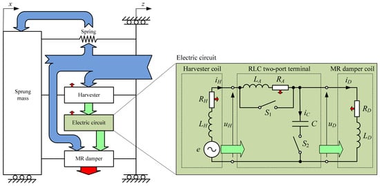
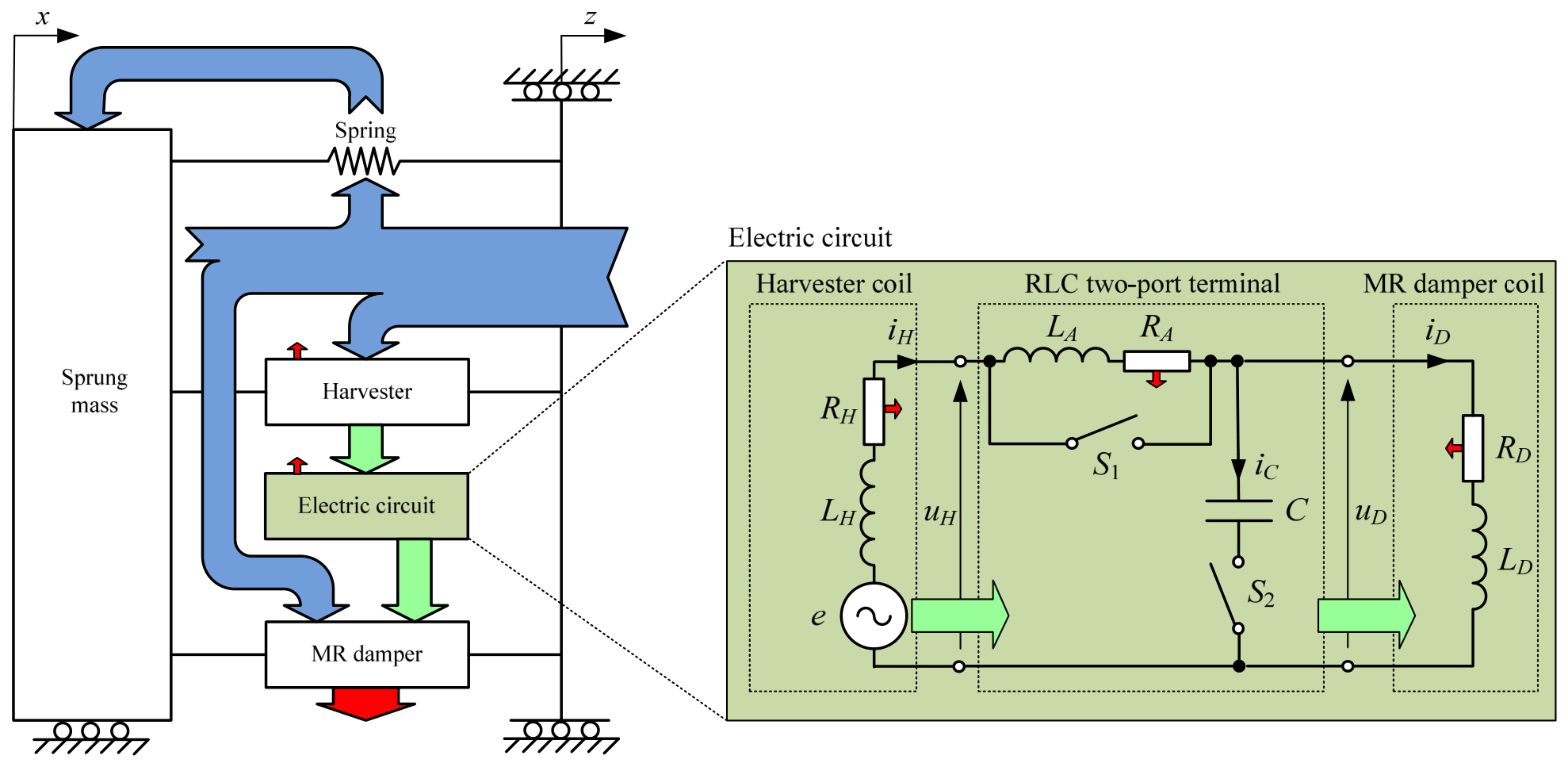
The purpose of the MR damper-based vibration reduction system, shown in Figure 1, is to reduce the amplitude of displacement x of the vibration-isolated mass. The system is set in motion by displacement z (kinematic excitation), which is generated by an electrodynamic shaker. The main components of the MRD-VRS are: the RD-8040-1 MR damper [41], plates with a mass of m = 115 kg (the vibration-isolated object), a spiral spring with a spring constant of k = 90,000 N/m, an electromagnetic harvester and an RLC two-port network [39] incorporated into the circuit. The natural frequency of the system is .
Figure 1.
Diagram of energy flow in the MRD-VRS with corresponding electric circuit.
Part of the mechanical energy generated by the shaker and transferred to the 1 DOF system (blue arrow) is stored by the spring as potential while the vibration-isolated object stores it as kinetic energy. The remainder is converted into electrical energy (green arrow) by the harvester, and into thermal energy (red arrow) mainly by the MR damper. The amount of mechanical energy converted into thermal energy by the MR damper is determined by the magnitude of the control current iD in its control coil.
In the steady-state vibration of the 1DOF mechanical system under consideration, there is a cyclic conversion of kinetic energy into potential energy, and vice versa, via the spring and the vibration-isolated object (see a closed loop shown in Figure 1). At the same time, all of the mechanical energy supplied by the electrodynamic shaker in the steady-state vibration condition is converted into thermal energy. Heat is generated in both the resistive components of the electrical circuit formed by the harvester coil, the RLC two-port network, and the MR damper’s control coil (see Figure 1) and in the MR damper itself due to friction during fluid flow. It should be noted that the amount of electrical energy converted into thermal energy in the electrical circuit is several dozen times smaller than the amount of mechanical energy converted into thermal energy by the MR damper. A detailed analysis of the energy balance in an MRD-VRS, in which the MR damper is supplied directly from the harvester, is described in [36].
The vibration amplitude of the vibration-isolated object x depends on the amount of kinetic energy accumulated in the 1DOF system. This, in turn, depends on the amplitude and frequency of the excitation z, as well as the amount of mechanical energy dissipated as heat by the MR damper. One measure of the effectiveness of MRD-VRS is the displacement transmissibility function, which is defined by Equation (1).
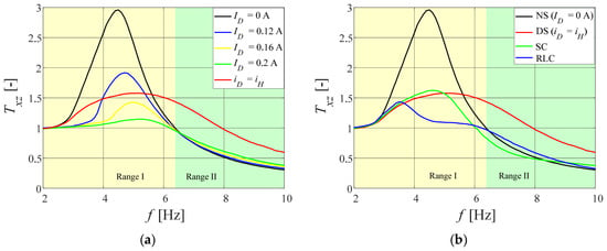
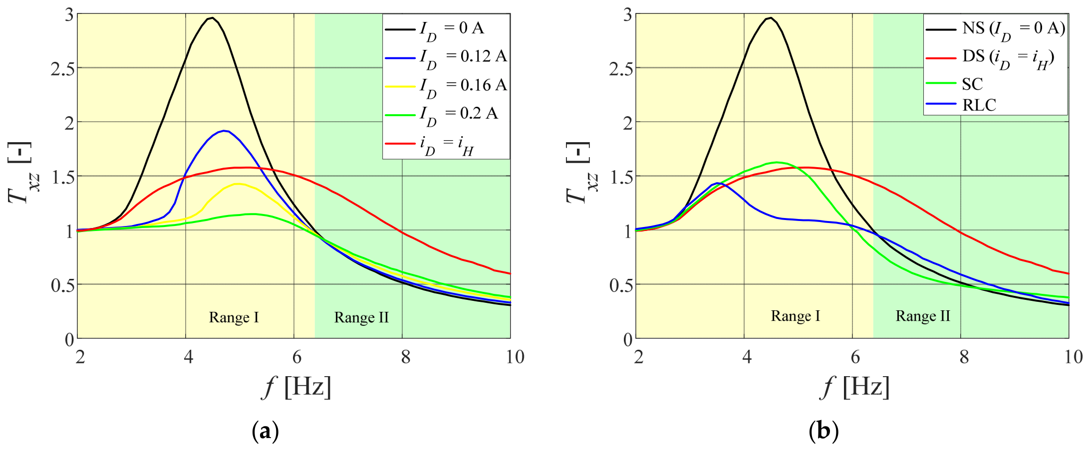
Figure 2a shows the displacement transmissibility function when the control coil of the MR damper is supplied by an external electrical source providing a constant current ID. Two frequency bands are visible, in which the following occurs:
Figure 2.
Displacement transmissibility of the MRD-VRS under harmonic excitation: (a) external powered; (b) self-powered.
- amplification of the vibration amplitude of the vibration-isolated object (Txz > 1)—Range I;
- attenuation of the vibration amplitude of the vibration-isolated object (Txz < 1)—Range II.
An increase in the current ID in Range I causes a decrease in Txz; however, in Range II, it causes an increase in Txz. All transmissibility functions intersect at the frequency , for which Txz = 1. This behaviour is characteristic of mechanical harmonic oscillators set in motion by kinematic excitation, i.e., motion transmitted to the vibration-isolated object via a spring and a damping element.
When the MR damper coil is supplied directly with the alternating voltage generated by the harvester (with switch S1 switched on and switch S2 switched off, as shown in the circuit diagram in Figure 1), the amplitude of vibrations in the vibration-isolated object will only be reduced in the vicinity of the resonance frequency fr (see plot DS in Figure 2b). In contrast, at frequencies f > fc, the values taken by the transmissibility function (Figure 2b) significantly exceed those obtained for constant currents in the control coil (Figure 2a). This is the main drawback of an MRD-VRS, where the electrical energy harvested from mechanical vibrations is used to power the MR damper’s control coil directly.
In order to enhance the performance of the MRD-VRS with an energy harvesting ability, an electrical energy conversion circuit must be introduced between the harvester coil and the MR damper coil. Experiments on a system in which the MR damper coil is supplied with direct current (Figure 2a) clearly showed that, for frequencies f > fc, the voltage source should be cut off from this coil. For this reason, additional coupling capacitors were connected in parallel with the MR damper coil, improving the performance of the vibration reduction system (see plot SC in Figure 2b). This forms a branched electrical circuit (with switches S1 and S2 switched on), which limits the current supplied to the control coil by routing most of the current through the coupling capacitors for high frequencies of the voltage generated in the harvester (high vibration frequency of the mechanical system). This is made possible by the capacitors’ decreasing impedance. However, this solution has one major drawback: a significant increase in the current drawn from the harvester as the frequency rises. This could potentially damage the harvester coil during long-term operation of the electromechanical vibration reduction system. Further details regarding this type of system can be found in [38].
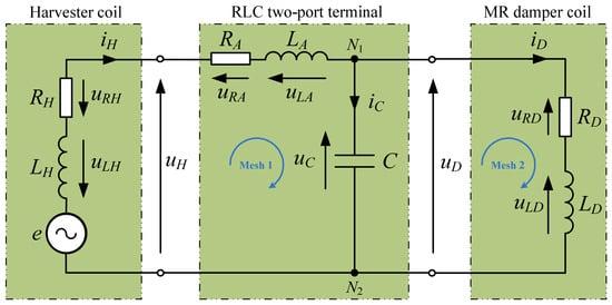
The proposed solution involves inserting an RLC two-port network (with switch S1 open and switch S2 closed) between the harvester coil and the MR damper. The purpose of the RLC two-port network is to induce electrical voltage resonance in the circuit. It should be emphasised that the term ‘voltage resonance’ used in this paper refers to the voltage-magnification effect in the loaded RLC two-port network (see Figure 3) rather than to the classical voltage resonance of an isolated series RLC circuit. The resulting increase in the output voltage UD relative to the harvester voltage UH can increase the MR damper current ID, although the current also depends on the impedance of the damper coil. Near resonance, energy is periodically exchanged between the magnetic field of the inductor L and the electric field of the capacitor C (within Mesh 1 shown in Figure 3), contributing to an increased output-voltage amplitude UD. This voltage-magnification effect and the associated change in the damper current do not imply energy generation or active amplification, since the passive RLC network only stores and releases energy supplied by the voltage source. Under steady-state periodic operation, the average active powers of the ideal inductor and capacitor over a complete cycle are zero. Furthermore, part of the energy supplied by the energy harvester is dissipated in the circuit’s resistive elements, while the remaining energy is transferred to the MR damper coil. In a practical implementation, additional losses may arise from the capacitor’s equivalent series resistance (ESR), leakage, and other parasitic effects, which are not included in the circuit model. All the electrical energy supplied to the MR coil via the RLC network originates exclusively from the energy harvester. The increase in the MR damper current ID achieved using voltage magnification in the branched circuit under consideration occurs at a frequency fIMAX that generally differs from the resonant frequency f0e of the isolated series RLC circuit. The consequence of resonance occurring in an electrical circuit is an increase in the damping force FD of the MR damper. The force FD is responsible for damping the vibrations of the vibration-isolated object. To improve the efficiency of the MRD-VRS with an energy harvesting ability, it is crucial to select the frequency fIMAX at which the current iD reaches its maximum value. This frequency should equal the frequency at which the vibration-isolated object’s vibrations are highest, as this is when the MR damper’s maximum damping force is required. Another important factor is damping in the RLC two-port network, as this significantly influences the value of the current iD at resonance and thus the effectiveness of the object’s vibration damping. The RLC two-port network also solves the issue of excessive current draw iH from the harvester at high frequencies, which occurred when only coupling capacitors were used. Experimental investigations of an electrical circuit comprising an RLC two-port network connected between the harvester coil and the MR damper are described in detail in [39]. Figure 2b compares the vibration transmissibility functions when the MR damper’s control coil is supplied with an alternating voltage uD derived.
Figure 3.
Electrical circuit of the MRD-VRS.
- directly from the harvester (DS);
- from the harvester via coupling capacitors (SC);
- from the harvester via an RLC two-port network (RLC).
In frequency range II, the vibration reduction system, which is equipped with both an RLC circuit and a circuit with coupling capacitors, significantly reduces the amplitude of vibrations in the vibration-isolated object, compared to a system in which the MR damper coil is powered directly from the harvester. The differences in vibration damping efficiency between the two circuits are negligible. The greatest differences, however, can be observed in frequency range I, where the MRD-VRS with an RLC circuit reduces the vibration amplitude of the object around the resonance frequency the most effectively. For the NS, DS, SC, and RLC configurations, the peak displacement transmissibility values were 2.918 (at 4.5 Hz), 1.595 (at 5.0 Hz), 1.625 (at 4.6 Hz), and 1.432 (at 3.5 Hz), respectively. Compared with the NS configuration, the peak displacement transmissibility was reduced by 45.3%, 44.3%, and 50.9% for the DS, SC, and RLC configurations, respectively.
This study aims to analyse the influence of RLC two-port network parameters on the performance of an MRD-VRS with an energy harvesting ability using computer simulations of the 1DOF system model. To achieve this objective, a mathematical model of the electrical circuit was developed and numerical simulations were carried out. The obtained results were then compared with experimental results during the validation process. Subsequently, a model of a vibration reduction system with an energy recovery function and an RLC circuit was constructed and analysed for its influence on vibration damping efficiency.
3. Electrical Circuit of the MR-Based Vibration Reduction System
Connecting the harvester coil to the MR damper’s control coil via an additional RLC two-port network located between them creates a branched electrical circuit, the schematic of which is shown in Figure 3. The harvester coil generates the supply voltage e as a result of the movement of the permanent magnets relative to it (in accordance with Faraday’s law). The harvester coil is a one-port electrical network with an inductance of LH = 7.5 mH and a resistance of RH = 0.1 Ω. Current flowing through the coil causes the voltage across the coil terminals to be less than the supply voltage e, due to voltage drops occurring across the coil’s inductance and resistance. The RLC two-port network contains an additional electrical coil with inductance LA and resistance RA. When the harvester coil is connected to the input of the RLC two-port network, Mesh 1 is formed, in which the resistors RH and RA, as well as the coils LH and LA, are connected in series. Consequently, in this article, we shall use the equivalent resistance R = RH + RA and the equivalent inductance L = LH + LA. The output of the RLC two-port network (the capacitor terminals) is connected to the MR damper coil, which is a one-port network with an inductance of LD = 100 mH and a resistance of RD = 4.5 Ω, forming Mesh 2.
3.1. Mathematical Model of the Circuit
The circuit’s mathematical model is expressed in matrix form (2), using Kirchhoff’s second law for meshes Mesh1 and Mesh2, and Kirchhoff’s first law for node N1.
Applying the Laplace transform to this model (2), with zero initial conditions assumed, yields the corresponding matrix form (3) in the complex number domain s.
Finally, the mathematical model of the electrical circuit under analysis can be expressed as a transfer matrix (4).
where
The circuit is powered by a voltage e(t), which is induced in the harvester’s coil by the harmonic motion of the mechanical system. Thus, determining the spectral transfer matrix H(jω), expressed by Equation (5), enables the calculation of the magnitudes M(ω) and phase shifts φ(ω), in accordance with Equations (6) and (7), for a harmonic voltage e(t).
where
The fundamental physical quantity that characterises an RLC two-port network in which voltage resonance occurs is its resonance frequency f0e, which is given by Equation (8). It is defined as the frequency at which the resultant reactance of the series RLC circuit is equal to zero. For a series RLC circuit, the quality factor Q is defined as the ratio of the voltage amplitude UC across the capacitor to the supply voltage amplitude UH under resonance conditions, as given by Equation (9).
As the circuit under analysis is branched, with the output of the RLC two-port network connected to the RDLD one-port network, the resonant frequency of the entire circuit is given by Equation (10). The configuration of the connections between the inductors, capacitors, and resistors in the circuit means that the resonance frequency fre and the frequency fIMAX at which the current iD reaches its maximum value are generally not equal. The reasons for these differences are described in [42]. An analytical formula for calculating fIMAX is given by Equation (11).
3.2. Simulation Results
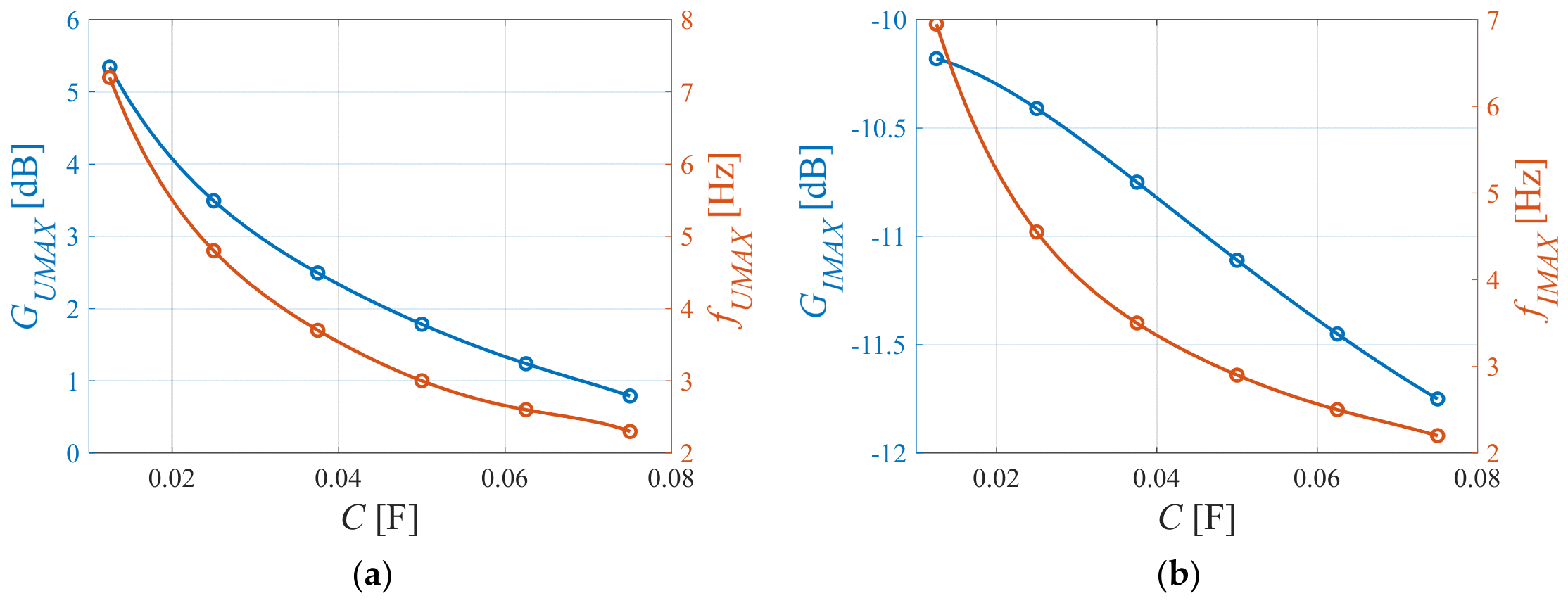
Numerical simulations of the electrical circuit shown in Figure 3 were carried out in the MATLAB 2020a environment. The results are presented as frequency responses examining the influence of the RLC two-port network parameters: inductance L (Figure 4), capacitance C (Figure 6), resistance R (Figure 8) and quality factor Q (Figure 10). The results presented are limited to the frequency responses of the GU and GI gains, as these determine the current in the MR damper coil and directly influence the force exerted on the mechanical structure. These gains were calculated in accordance with Equations (12) and (13). The maximum values of the gain factors GUMAX and GIMAX observed in these characteristics correspond to the frequencies fUMAX and fIMAX. The base parameters used in the computer simulations of the circuit were: L = 50.2 mH, C = 33 mF, R = 0.65 Ω, LD = 100 mH and RD = 4 Ω. Numerical simulations were carried out for frequencies ranging from 0.1 to 10 Hz.
Figure 4 shows the frequency characteristics of the GU and GI gain plots (Figure 4a and Figure 4b, respectively) for variations in inductance L in the range from 25 mH to 150 mH in increments of 25 mH. Figure 5 shows the relationship between the maximum gain values GUMAX and GIMAX, together with their corresponding frequencies fUMAX and fIMAX, and the inductance L. An increase in inductance L results in a decrease in both frequency fUMAX (Figure 5a) and fIMAX (Figure 5b). Furthermore, the gain factor values GUMAX (Figure 5a) and GIMAX (Figure 5b) increase, but only when the inductance respects the following conditions: L < 62 mH and L < 90 mH, respectively. At a frequency of f = 0.1 Hz, the values of GU and GI are −1.3 dB (Figure 4a) and −13.3 dB (Figure 4b) respectively. In the case of GU, this is due to the voltage drop across the resistance R caused by the current flow iH, while GI is inversely proportional to the sum of the resistances R + RD. The effect of changing the capacitance C of the RLC two-port network on the frequency characteristics of the gains is shown in Figure 6. Increasing C from 12.5 to 75 mF reduces both fUMAX (Figure 7a) and fIMAX (Figure 7b), as well as both GUMAX (Figure 7a) and GIMAX (Figure 7b).
Figure 4.
Frequency responses of the electrical circuit at various inductance L values: (a) voltage gain GU; (b) current gain GI.
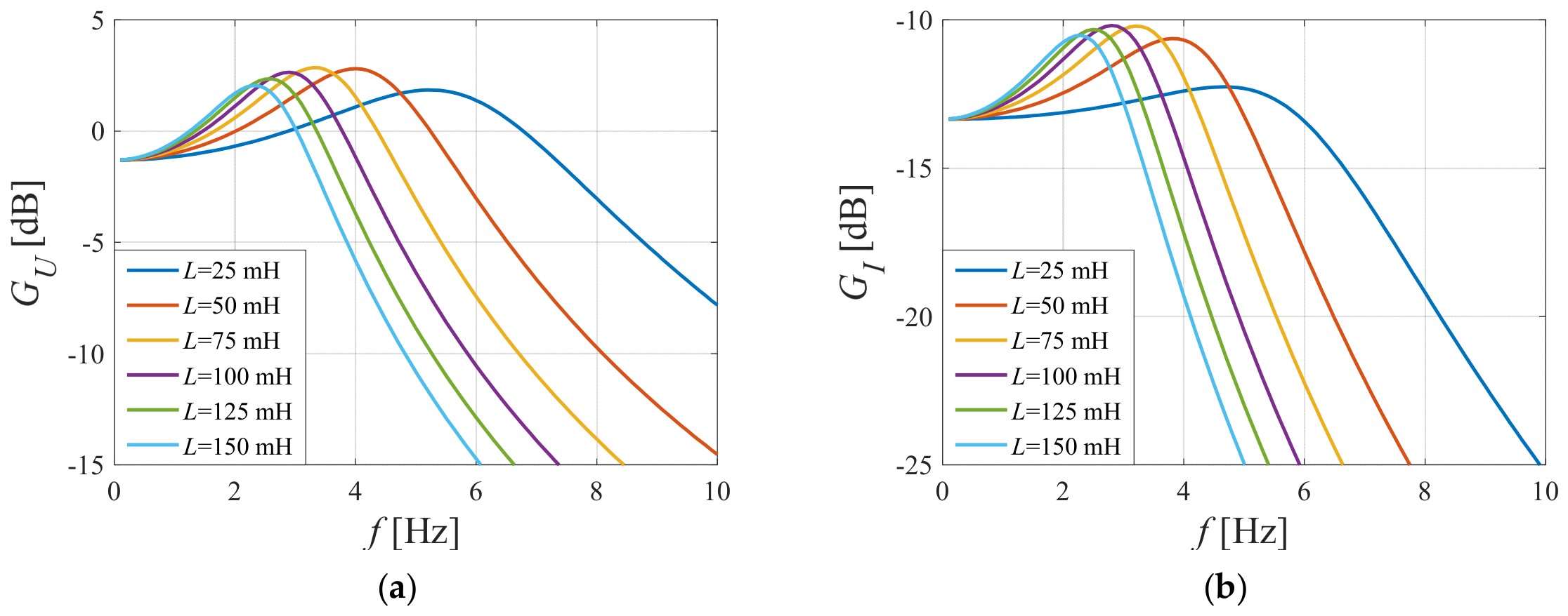
Figure 5.
Maximum gain and corresponding frequency vs. inductance L: (a) GUMAX and fUMAX; (b) GIMAX and fIMAX.
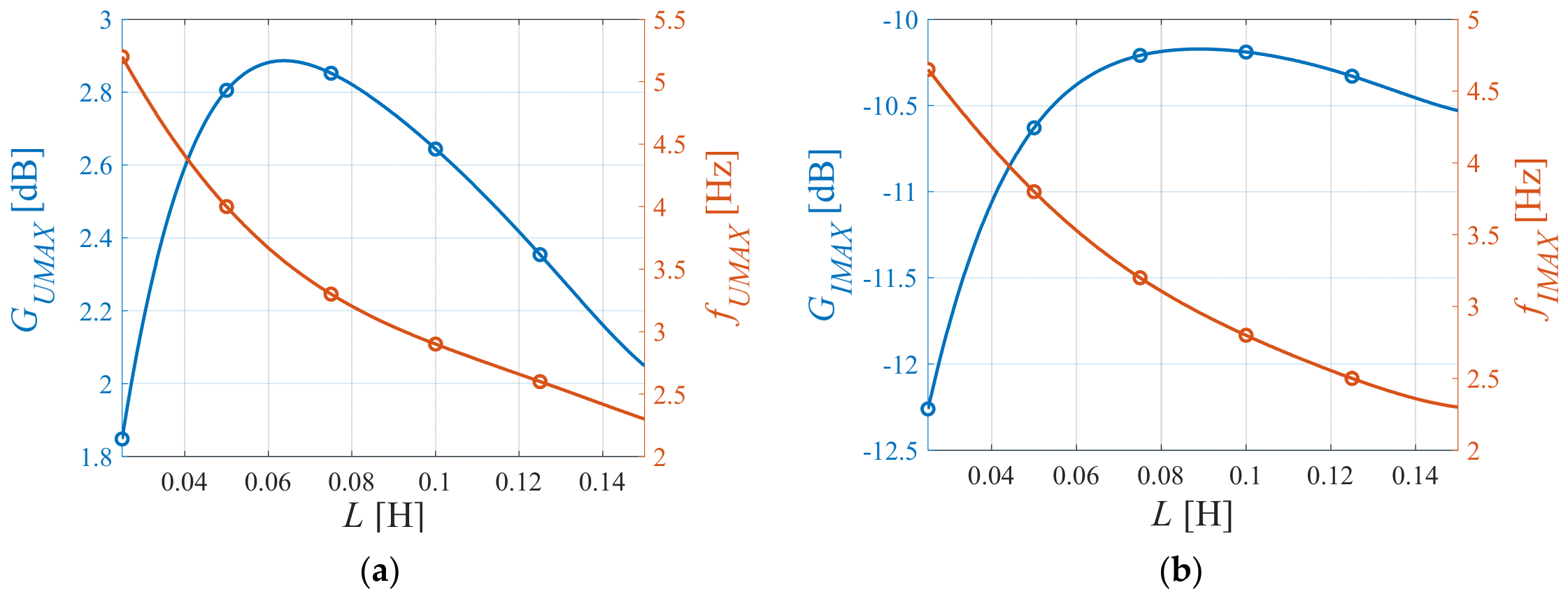
Figure 6.
Frequency responses of the electrical circuit at various capacitance C values: (a) voltage gain GU; (b) current gain GI.
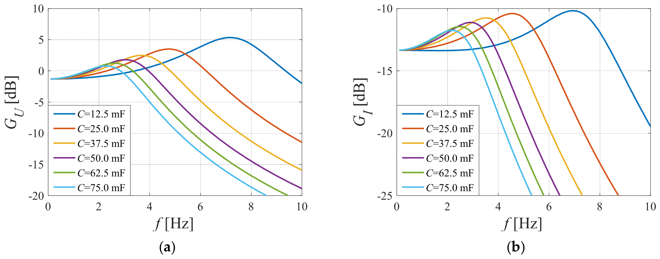
Figure 7.
Maximum gain and corresponding frequency vs capacitance C: (a) GUMAX and fUMAX; (b) GIMAX and fIMAX.
The resistance R has a significant impact on the gain values of GUMAX and GIMAX. Increasing R primarily reduces both gain values. Moreover, when R > 1.4 Ω, the maximum of the GI frequency response shown in Figure 8b does not occur. The frequencies fUMAX (Figure 9a) and fIMAX (Figure 9b) also decrease. Furthermore, the voltage uD (Figure 8a) and the current iD (Figure 8b) decrease across the entire frequency range f. Assuming that using an RLC circuit in a vibration reduction system only improves its efficiency when the current iD increases by at least 25% in the resonance state (GIMAX = −11.4 dB), the resistance R should be less than 0.75 Ω.
Figure 8.
Frequency responses of the electrical circuit at various resistance R values: (a) voltage gain GU; (b) current gain GI.
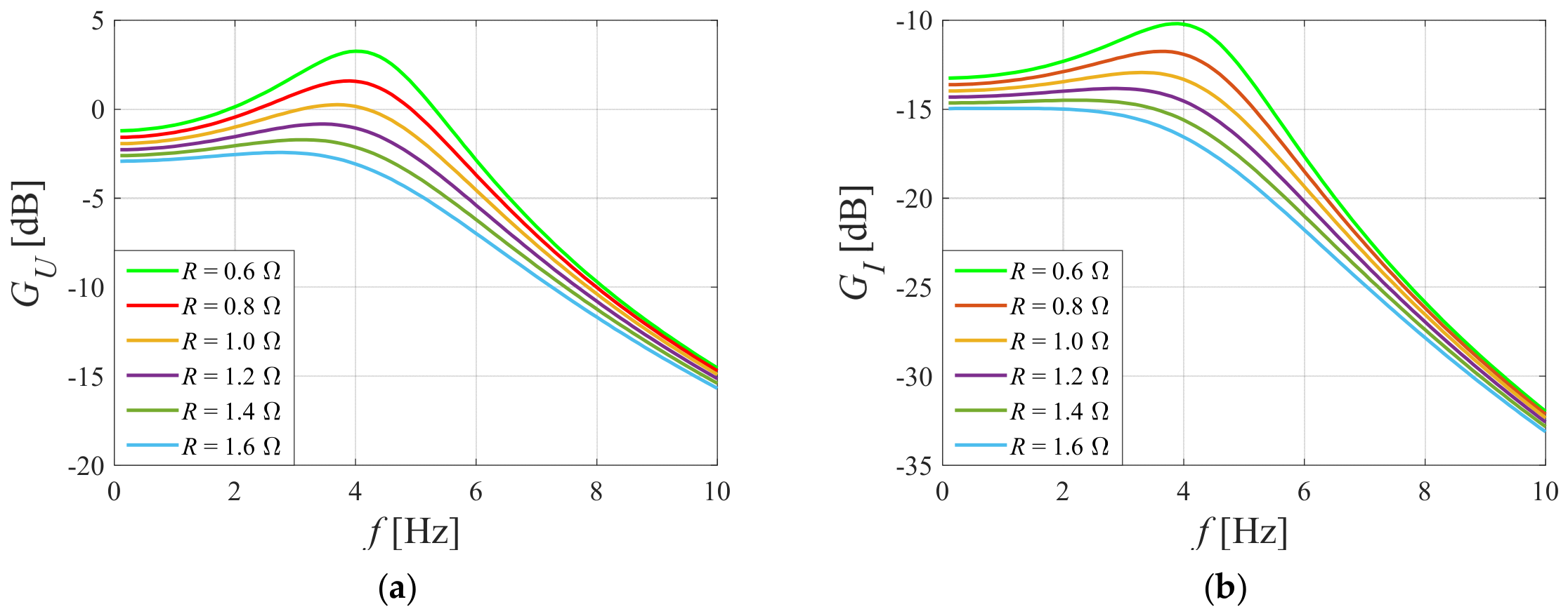
Figure 9.
Maximum gain and corresponding frequency vs resistance R: (a) GUMAX and fUMAX; (b) GIMAX and fIMAX.
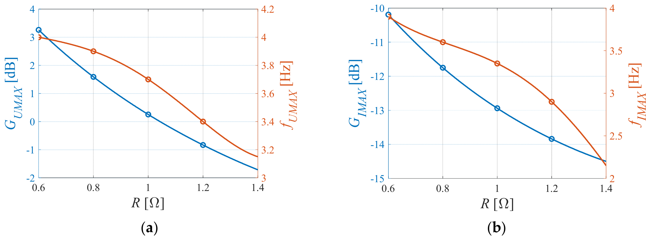
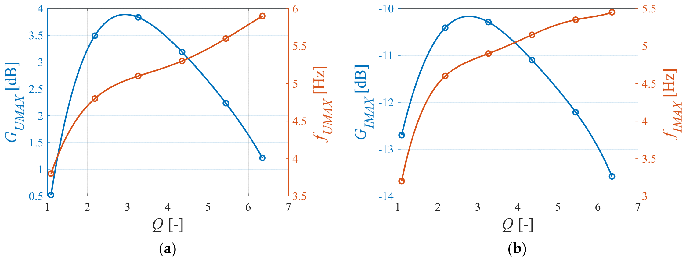
Figure 10 shows the frequency responses of the GU (Figure 10a) and GI (Figure 10b) gains, plotted for a fixed frequency f0e = 4.5 Hz and a variable quality factor Q of the RLC two-port network. The chosen frequency f0e corresponds to the resonance frequency f0m of the mechanical system (the maximum vibration amplitude of the vibration-isolated object). The inductance L was varied in steps of 25 mH over the range from 25 mH to 150 mH. The capacitance C was calculated using Equation (8) to ensure a constant frequency f0e. The Q-factor of the RLC two-port network varied from 1.09 to 6.53. An increase in the Q-factor results in an increase in the frequencies fUMAX (Figure 11a) and fIMAX (Figure 11b). The maximum gain values, GUMAX = 3.8 dB (Figure 10a) and GIMAX = −10.31 dB (Figure 10b), were observed for a Q-factor of 3.26 (L = 75 mH and C = 16.7 mF). The frequency fIMAX was then 4.9 Hz, which means that the maximum current iD in the MR damper coil was obtained at a frequency higher than the resonance frequency frm of the 1DOF system. To achieve the maximum MR damper force at the frequency fIMAX = frm, the Q-factor must be 2.18 (L = 50 mH, C = 25 mF). This results in slightly lower gain values, GUMAX and GIMAX.
Figure 10.
Frequency responses of the electrical circuit at various quality factor Q values: (a) voltage gain GU; (b) current gain GI.
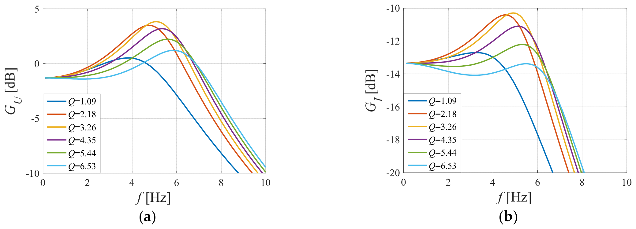
Figure 11.
Maximum gain and corresponding frequency vs quality factor Q: (a) GUMAX and fUMAX; (b) GIMAX and fIMAX.
3.3. Validation of the Circuit
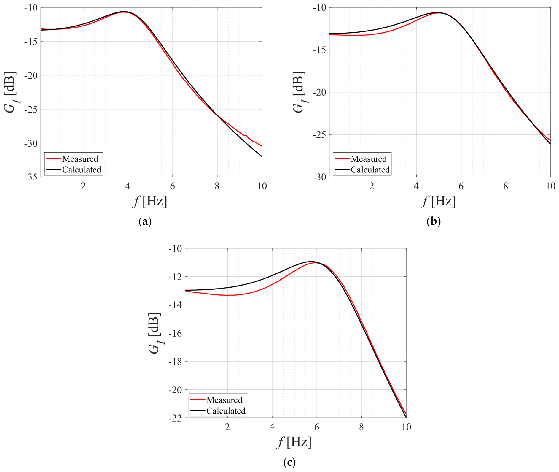
Figure 12 shows a comparison of the numerical results for the circuit with the experimental results described in [39]. The experiments used an additional electrical coil with the three winding sections:
Figure 12.
Current gain GI vs. excitation frequency f for coil taps corresponding with: (a) LA1 and RA1, (b) LA2 and RA2, and (c) LA3 and RA3.
The required circuit capacitance C was achieved by connecting 18 bipolar electrolytic capacitors, each with a capacitance of 2200 μF, in parallel. This resulted in a nominal capacitance of 39.6 mF. However, the total measured capacitance C was lower than the nominal value, amounting to 33 mF. The measured capacitance was used in the numerical simulations to reflect the actual parameters of the circuit used in the experiments. The effects of component tolerances, parasitic resistance in the connecting wires, and temperature variations were not quantified separately. There was a very high degree of agreement between the simulation and experimental results for the electrical circuit under consideration. The resonance phenomenon enabled the maximum current value iD to be achieved at the following frequencies: fIMAX = 3.8 Hz (Figure 12a), fIMAX = 5 Hz (Figure 12b) and fIMAX = 5.9 Hz (Figure 12c).
4. MR-Based Vibration Reduction System
4.1. Mathematical Model of the System
The mathematical model of the MRD-VRS with the RLC two-port network in its electrical circuit is expressed by Equation (14). According to d’Alembert’s principle, a mechanical system can be considered to be in dynamic equilibrium when the sum of the external and inertial forces is zero at any given instant. For the system under consideration, the force balance includes the spring force FS, the MR damper force FD, the force generated by the harvester FH, and the inertial force. The FH results from the flow of current iH through the harvester coil. The damping force FD generated by the MR damper depends non-linearly on the piston velocity relative to the cylinder and the current iD. The damping force model takes into account the mechanical hysteresis of the MR damper using the hyperbolic tangent function [43,44]. The parameters of this model were identified for fixed values of the direct current ID flowing through the MR damper coil. While the identified FD force model accurately reproduces the experimental characteristics of the MR damper under constant ID conditions, discrepancies arise when iD varies over time. These discrepancies result from the finite response time of the MR damper force to changes in the coil current. This dynamic response is associated with the time required for the MR fluid to adjust its internal structure to changes in the applied magnetic field. Therefore, to account for the dynamic response of the MR damper, the model parameters C0 and C1 are defined as functions of the effective current ieff. The relationship between the coil current iD and the effective current ieff is described by a first-order transfer function. The relationships between the harvester current iH and the damper current iD, and between the current iD and the electromotive force e, follow from the electrical circuit model described by Equation (2).
Several simplifying assumptions were adopted in the model. The cogging force generated by the interaction between the harvester’s permanent magnets and its ferromagnetic elements, as well as the electrical losses associated with eddy currents in the magnetic circuit, were neglected. Magnetic saturation and hysteresis losses in the MR damper’s magnetic circuit were also not explicitly considered. The first-order transfer function relating iD to ieff was introduced to reproduce the behaviour of the 1DOF system when the MR damper coil was powered directly by the energy harvester. Its time constant was adjusted to obtain agreement between the modelled and observed system behaviour; it was not determined through an independent experimental measurement of the MR fluid or force response time. Consequently, the accuracy of this approximation when the effective current deviates from the conditions used for parameter tuning, particularly under transient or non-sinusoidal excitation, remains to be assessed.
4.2. Validation of the System
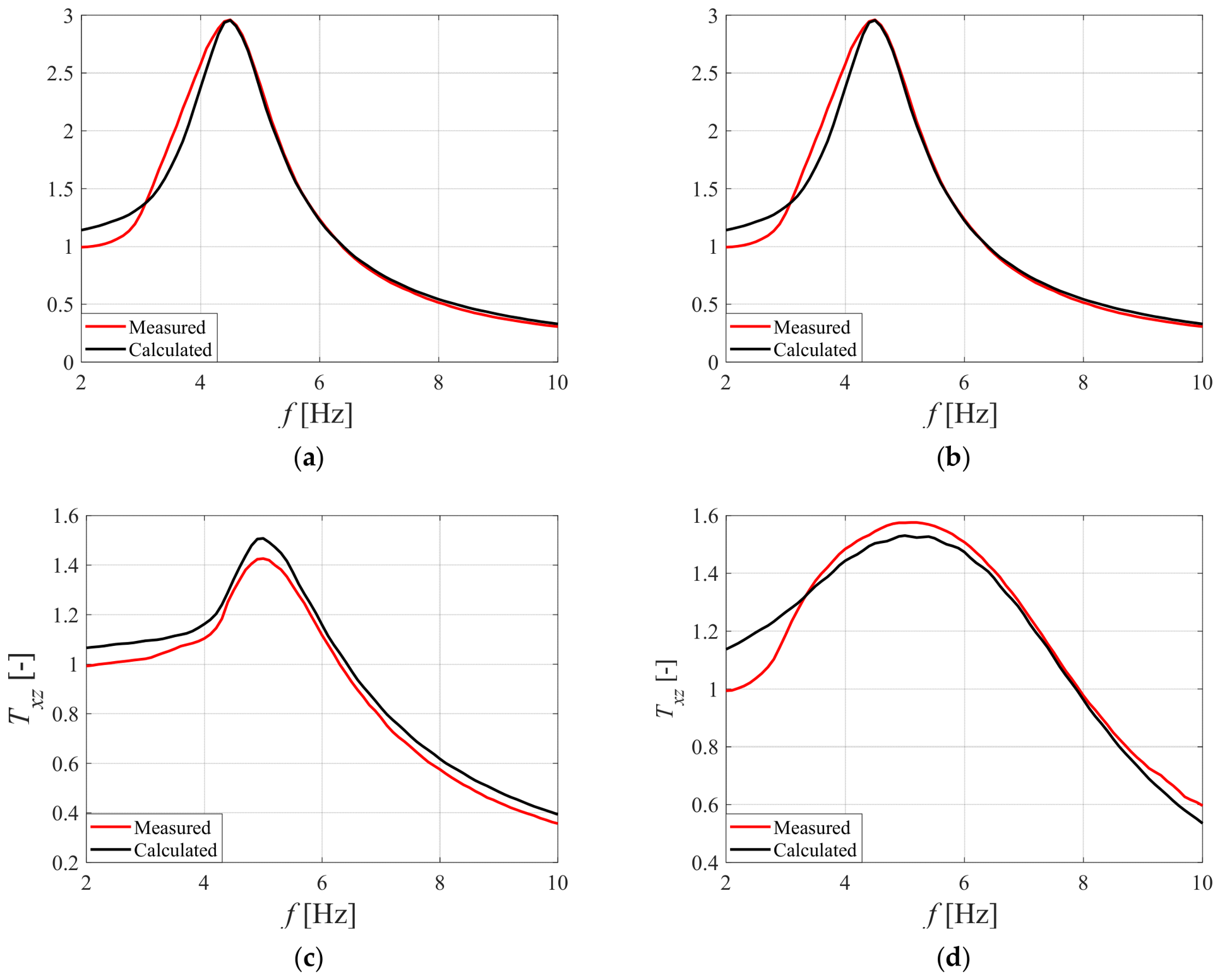
Numerical simulations were carried out for the model described by Equation (14) in the MATLAB 2020a environment. A kinematic excitation, z(t) = Asin(2πft), was assumed, with an amplitude of A = 3.5 mm and a frequency f that varied by 0.1 Hz within the range from 2 Hz to 10 Hz. These excitation parameters correspond to those that can be achieved on a test rig. The following base model parameters were adopted for the simulation: object mass, m = 115 kg; spring stiffness, k = 90,000 N/m; electrical constant of the harvester, κ = 14 V·s/m; time constant, TC = 5 ms; damper coil resistance, RD = 4.5 Ω; damper coil inductance, LD = 100 mH; RLC two-port network inductance, L = 50 mH; RLC two-port network resistance, R = 0.65 Ω; and RLC two-port network capacitance of C = 25 mF for f0e = 4.5 Hz and C = 33 mF for f0e = 4 Hz. The MR damper model parameters were set as follows: β = 50 s/m, p1 = 4 1/s, p2 = 0.2 1/s, b1 = 3894 N/A2, b2 = 106.4 N/A, b3 = 84.9 N, b4 = 2889 Ns/A2m, b5 = 22.3 Ns/Am, b6 = 733.1 Ns/m.
The mathematical model developed for the MRD-VRS was subjected to experimental verification. The experimental setup and measurement methodology are described in detail in [35]. The measurements were performed using two laser triangulation sensors to measure the displacement of the shaker plate, representing the kinematic excitation, and the displacement of the vibration-isolated object. The transmissibility function Txz(f) was then determined from the measured displacements according to Equation (3). All measured mechanical and electrical quantities were converted into voltage signals and acquired using a data acquisition card with an input voltage range of ±10 V and a sampling frequency of 1 kHz.
The numerical and experimental results are presented in frequency response plots (Figure 13). The transmissibility functions Txz(f) were compared in the following scenarios: when the MR damper’s control coil was not supplied (Figure 13a), when it was supplied by constant currents ID = 0.12 A (Figure 13b) and ID = 0.16 A (Figure 13c); and when it was supplied by alternating voltage directly from the harvester (Figure 13d). The results confirmed a high degree of agreement between the model simulation results for the assumed parameters and the experimental tests of the MRD-VRS.
Figure 13.
Transmissibility Txz vs. frequency f: (a) ID = 0 A, (b) ID = 0.12 A, (c) ID = 0.16 A, and (d) iD= iH.
4.3. Tuning of the RLC Two-Port Network Parameters
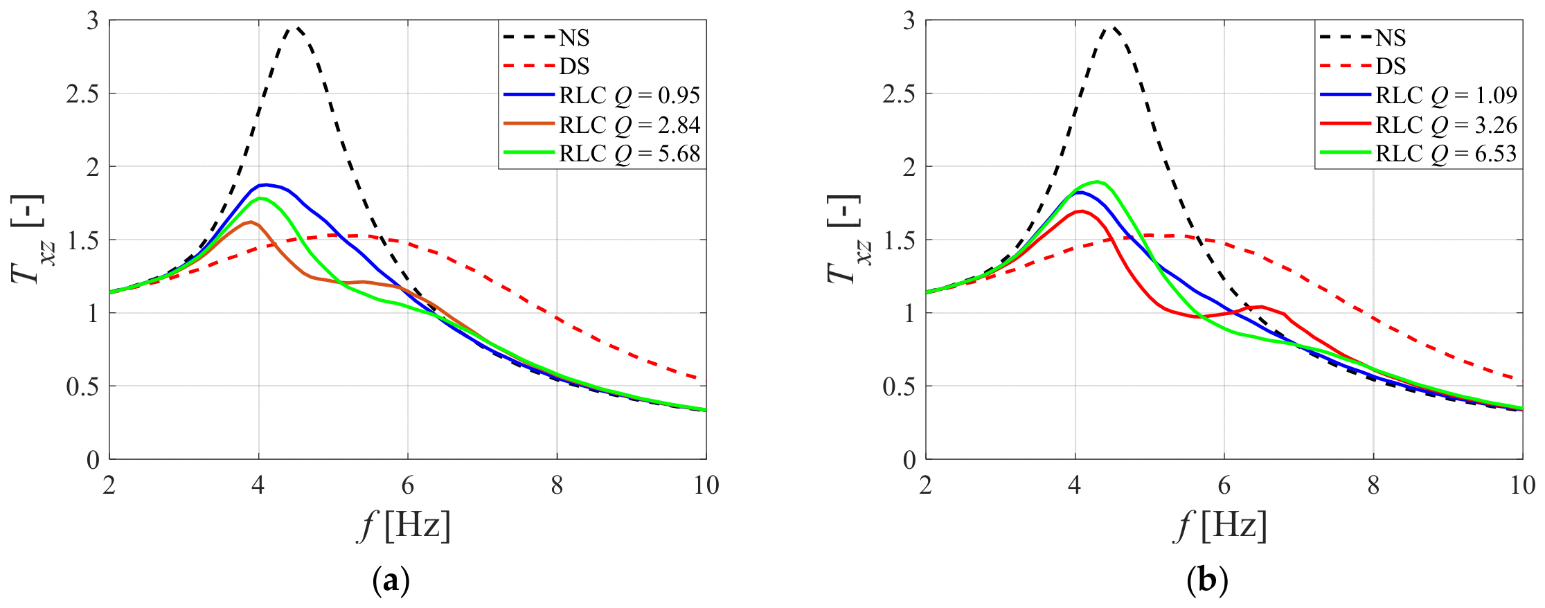
The selection of parameters for the RLC two-port network began with the determination of the influence of the circuit’s Q-factor on the transmissibility functions, Txz(f), at frequencies of f0e = 4 Hz and f0e = 4.5 Hz (see Figure 14a and Figure 14b, respectively). The lowest maximum value of Txz(f) was observed at a Q-factor of 2.84 (Figure 14a) and 3.26 (Figure 14b). Both decreasing and increasing the Q-factor relative to these values resulted in an increase in the vibration amplitude of the vibration-isolated object. This is due to the highest GIMAX gain values were obtained for these Q-factors, as can be clearly seen in the graphs in Figure 10b and Figure 11b. Therefore, changing parameters L and C to increase the Q-factor of the RLC two-port network at a constant resonance frequency f0e improves the vibration reduction system’s effectiveness when Q < Qmax. In the circuit under consideration, the limit value Qmax can be determined using the circuit simulation results shown in Figure 11b. Furthermore, lower vibrations of the object across the entire frequency range were achieved when f0e = 4 Hz (compare plots in Figure 14a and Figure 14b). When f0e = 4.5 Hz and the Q-factor was 3.26, a second maximum was observed on the frequency response plot. This caused an increase in the amplitude of the object’s vibrations when f > 6.5 Hz. This effect is due to the frequency fIMAX (Equation (11)) being greater than the frequency f0e (Equation (8)) of the RLC two-port network. Therefore, the frequency f0e selected in practice should be slightly lower than the frequency f0m of the 1DOF system. This follows directly from the previously described properties of the electrical circuit, which is a branched circuit.
Figure 14.
Transmissibility Txz vs. frequency f at various quality factor Q values of the RLC two-port network: (a) f0e = 4 Hz; (b) f0e = 4.5 Hz.
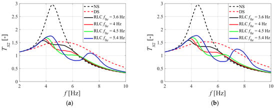
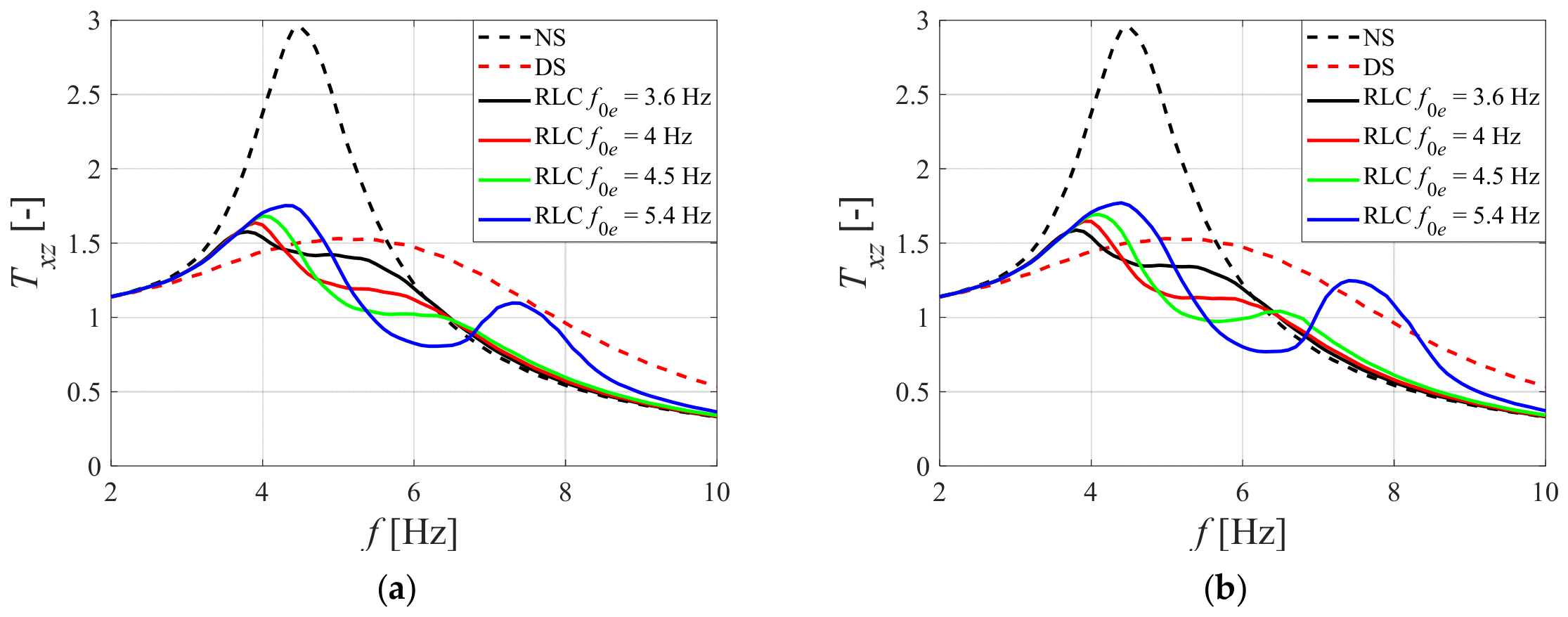
Previous results show that correctly selecting the frequency f0e of the RLC two-port network is key to improving the performance of the MRD-VRS. In view of this, the influence of the f0e frequency was analysed for two selected circuit quality factors: Q = 2.18 (Figure 15a) and Q = 3.26 (Figure 15b). An increase in f0e results in an increase in the maximum displacement transmissibility coefficient Txz value and the frequency at which it occurs. When f0e > f0m, a second, distinct peak appears on the Txz(f) frequency response plot, increasing the amplitude of the object’s vibrations when f > 6.5 Hz. RLC two-port networks with resonance frequencies of f0e = 4 Hz and f0e = 4.5 Hz achieved the most effective damping of mechanical vibrations across the entire frequency range. For lower Q-factors, it is preferable to select a circuit that satisfies the condition f0e = f0m (Figure 15a), whereas for higher Q-factors, f0e < f0m (Figure 15b).
Figure 15.
Transmissibility Txz vs. frequency f at various resonant frequency f0e values of the RLC two-port network: (a) Q = 2.18; (b) Q = 3.26.
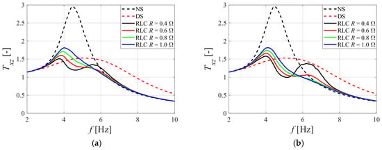
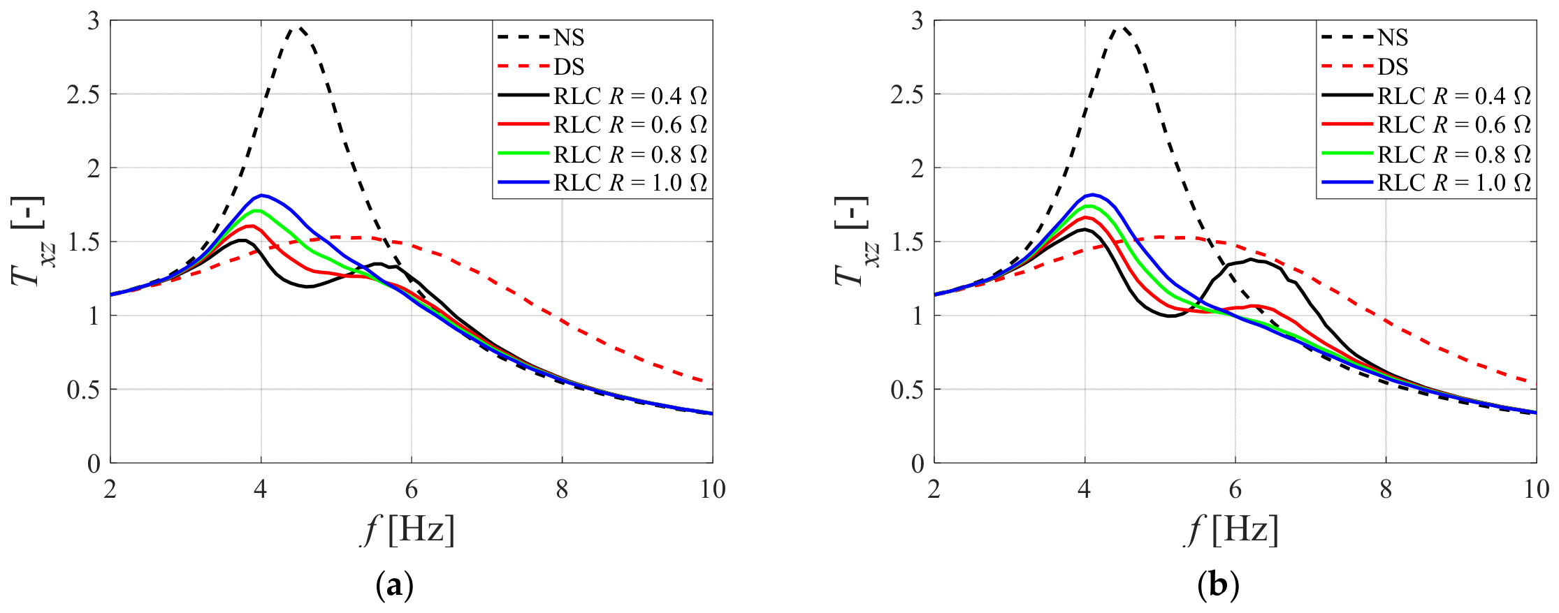
As shown in Figure 16, the resistance R of the RLC two-port network has a significant impact on the effectiveness of the MRD-VRS. Reducing R decreases the maximum value of Txz. However, when R is less than 0.6 Ω, a second maximum begins to appear in the characteristic plot, which reduces the efficiency of the vibration damping when f is greater than 6.5 Hz. The transmissibility function Txz(f) value at the local minimum decreases and occurs at f = 4.5 Hz. This local minimum occurs due to the anti-resonance phenomenon present in a system of two coupled harmonic oscillators (a mechanical oscillator coupled to an RLC two-port network). The MRD-VRS equipped with an RLC two-port network with a resistance of R = 0.6 Ω demonstrates the highest vibration damping efficiency across the entire range of excitation frequencies.
Figure 16.
Transmissibility Txz vs. frequency f at various circuit resistance R values: (a) f0e = 4 Hz; (b) f0e = 4.5 Hz.
5. Conclusions
This study presents a practical application of the voltage resonance phenomenon to improve the efficiency of the MRD-VRS with energy harvesting ability. In a typical system, connecting the harvester coil directly to the MR damper’s control coil is problematic because high-frequency vibrations are not properly damped. The solution is to incorporate an additional electrical circuit between the coils to modulate the current in the MR damper coil, thereby improving the effectiveness of mechanical vibration damping. Using an RLC two-port network allows the current in the MR damper coil to be increased selectively at the resonant frequency of the mechanical system, while cutting off the current at high frequencies. This results in high damping around the resonance frequency and low damping above it, enabling a reduction in the object’s vibrations across the entire range of excitation frequencies.
The resulting electrical circuit is branched, causing the frequency at which the current reaches its maximum to differ from the resonant frequency of the RLC two-port network. For this reason, an analysis was carried out to examine how circuit parameters influence the frequency characteristics of voltage and current gain. A mathematical model of the circuit was developed and an analytical formula was provided to calculate the frequency at which the current reaches its maximum value. Analysis of the results obtained from numerical simulations showed that there exists a set of parameters R, L and C at which voltage resonance occurs, which has practical application in a vibration reduction system. The results of the numerical simulations were also found to be in very close agreement with the experimental results for the circuit comprising the harvester coil, the MR damper and the RLC two-port network.
The mathematical model of the electromechanical vibration reduction system used an MR damper model described by hyperbolic tangent functions. It should be noted that the MR damper force model was identified under constant-current conditions and extended with a first-order dynamic element to approximately account for the damper response to time-varying current. Although this approach improves the representation of the damper dynamics, it may not capture all physical phenomena affecting the force under dynamic electrical excitation. In particular, the effects of phase shifts between the MR damper current and the relative piston velocity on the instantaneous damping force require further research. The parameters of the entire model were selected so that the simulation results would be consistent with those of the real vibration reduction system. The comparisons of numerical results against experimental data are presented for cases where the damper coil was not powered, was powered by direct current and was powered by alternating current supplied directly from the harvester. The high degree of agreement between the simulation and experimental results confirmed the model’s suitability for further numerical investigation of the influence of the RLC two-port network parameters on the vibration reduction system’s effectiveness. The analysis primarily focused on the influence of the circuit’s Q-factor, resonant frequency f0e and resistance R. On this basis, the following practical conclusions were drawn:
- resonant frequency f0e of the RLC two-port network should be close to, but not greater than, the frequency f0m of the 1DOF mechanical system;
- the Q-factor of the RLC two-port network should be within the range 2–3.5;
- the resistance R should be within the range of 0.6 Ω to 0.75 Ω.
The recommended ranges of the Q-factor and resistance R, as well as the selection of the resonant frequency f0e, were determined for the specific 1DOF mechanical system considered in this study and should not be regarded as universal design guidelines. Their sensitivity to variations in mass, stiffness, and mechanical resonance frequency, as well as the resulting impact on vibration reduction performance, require further investigation, particularly when these parameters change during operation. The results clearly demonstrated that using an RLC two-port network with correctly selected parameters significantly improves the performance of the MRD-VRS with energy harvesting ability. Although the electrical circuit and the MR damper-based vibration reduction system without the RLC two-port network were experimentally validated separately, experimental validation of the complete system incorporating the RLC two-port network will be addressed in subsequent research. Moreover, the energy balance of a vibration reduction system incorporating an RLC two-port network will be analysed in future work.
Author Contributions
Conceptualization, Ł.J. and B.S.; methodology, Ł.J. and B.S.; software, Ł.J.; validation, Ł.J.; formal analysis, Ł.J.; investigation, Ł.J.; writing—original draft preparation, Ł.J.; writing—review and editing, B.S.; supervision, B.S.; project administration, B.S. All authors have read and agreed to the published version of the manuscript.
Funding
This work was supported in part by the AGH University of Krakow through the Scope of the Excellence Initiative–Research University and in part by Research Program 501.00.10000.1300301.
Data Availability Statement
The original contributions presented in this study are included in the article. Further inquiries can be directed to the corresponding author.
Conflicts of Interest
The authors declare no conflict of interest.
References
- Zhu, X.; Jing, X.; Cheng, L. Magnetorheological Fluid Dampers: A Review on Structure Design and Analysis. J. Intell. Mater. Syst. Struct. 2012, 23, 839–873. [Google Scholar] [CrossRef] [Scilit]
- Gołdasz, J.; Sapiński, B.; Jastrzębski, Ł. Assessment of the Magnetic Hysteretic Behaviour of MR Dampers through Sensorless Measurements. Shock Vib. 2018, 2018, 3740208. [Google Scholar] [CrossRef] [Scilit]
- Gołdasz, J.; Sapiński, B.; Jastrzębski, Ł.; Kubik, M. Dual Hysteresis Model of MR Dampers. Front. Mater. 2020, 7, 236. [Google Scholar] [CrossRef] [Scilit]
- Abdul Aziz, M.; Mohtasim, S.M.; Ahammed, R. State-of-the-Art Recent Developments of Large Magnetorheological (MR) Dampers: A Review. Korea Aust. Rheol. J. 2022, 34, 105–136, Correction in Korea Aust. Rheol. J. 2022, 34, 241. [Google Scholar] [CrossRef] [Scilit]
- Wang, Z.; Liu, C.; Zheng, X.; Zhao, L.; Qiu, Y. Advancements in Semi-Active Automotive Suspension Systems with Magnetorheological Dampers: A Review. Appl. Sci. 2024, 14, 7866. [Google Scholar] [CrossRef] [Scilit]
- Dong, L.; Chen, Z.; Sun, M.; Sun, Q. Phase Compensation Active Disturbance Rejection Control for Shimmy Vibration with Magnetorheological Damper of Aircraft. Expert Syst. Appl. 2023, 213, 119126. [Google Scholar] [CrossRef] [Scilit]
- Liu, G.; Gao, F.; Wang, D.; Liao, W.-H. Medical Applications of Magnetorheological Fluid: A Systematic Review. Smart Mater. Struct. 2022, 31, 043002. [Google Scholar] [CrossRef] [Scilit]
- Yun, D.; Park, C.; Park, D.; Kim, H. Magnetorheological Damper for Vibration Reduction in a Robot Arm. Intell. Serv. Robot. 2022, 15, 671–678. [Google Scholar] [CrossRef] [Scilit]
- Harb, A. Energy Harvesting: State-of-the-Art. Renew. Energy 2011, 36, 2641–2654. [Google Scholar] [CrossRef] [Scilit]
- Siang, J.; Lim, M.H.; Leong, M.S. Review of Vibration-Based Energy Harvesting Technology: Mechanism and Architectural Approach. Int. J. Energy Res. 2018, 42, 1866–1893. [Google Scholar] [CrossRef] [Scilit]
- Wei, C.; Jing, X. A Comprehensive Review on Vibration Energy Harvesting: Modelling and Realization. Renew. Sustain. Energy Rev. 2017, 74, 1–18. [Google Scholar] [CrossRef] [Scilit]
- Sun, R.; Zhou, S.; Cheng, L. Ultra-Low Frequency Vibration Energy Harvesting: Mechanisms, Enhancement Techniques, and Scaling Laws. Energy Convers. Manag. 2023, 276, 116585. [Google Scholar] [CrossRef] [Scilit]
- Priya, S.; Inman, D.J. (Eds.) Energy Harvesting Technologies; Springer: Boston, MA, USA, 2009. [Google Scholar] [CrossRef] [Scilit]
- Sapiński, B. An Experimental Electromagnetic Induction Device for a Magnetorheological Damper. J. Theor. Appl. Mech. 2008, 46, 933–947. [Google Scholar]
- Singh, S.; Satpute, N.V. Design and Analysis of Energy-Harvesting Shock Absorber with Electromagnetic and Fluid Damping. J. Mech. Sci. Technol. 2015, 29, 1591–1605. [Google Scholar] [CrossRef] [Scilit]
- Zuo, L.; Scully, B.; Shestani, J.; Zhou, Y. Design and Characterization of an Electromagnetic Energy Harvester for Vehicle Suspensions. Smart Mater. Struct. 2010, 19, 045003. [Google Scholar] [CrossRef] [Scilit]
- Shen, Y.; Lu, K. Scavenging Power from Ultra-Low Frequency and Large Amplitude Vibration Source through a New Non-Resonant Electromagnetic Energy Harvester. Energy Convers. Manag. 2020, 222, 113233. [Google Scholar] [CrossRef] [Scilit]
- Xie, L.; Li, J.; Li, X.; Huang, L.; Cai, S. Damping-Tunable Energy-Harvesting Vehicle Damper with Multiple Controlled Generators: Design, Modeling and Experiments. Mech. Syst. Signal Process. 2018, 99, 859–872. [Google Scholar] [CrossRef] [Scilit]
- Kim, J.W.; Salauddin, M.; Cho, H.; Rasel, M.S.; Park, J.Y. Electromagnetic Energy Harvester Based on a Finger Trigger Rotational Gear Module and an Array of Disc Halbach Magnets. Appl. Energy 2019, 250, 776–785. [Google Scholar] [CrossRef] [Scilit]
- Zhang, Y.; Zhang, X.; Zhan, M.; Guo, K.; Zhao, F.; Liu, Z. Study on a Novel Hydraulic Pumping Regenerative Suspension for Vehicles. J. Frankl. Inst. 2015, 352, 485–499. [Google Scholar] [CrossRef] [Scilit]
- Scruggs, J.; Lindner, D.K. Active Energy Control in Civil Structures. In Proceedings of the Smart Structures and Materials 1999: Smart Systems for Bridges, Structures, and Highways, Newport Beach, CA, USA, 1–2 March 1999; SPIE: Bellingham, WA, USA, 1999; Volume 3671, pp. 194–205. [Google Scholar]
- Cho, S.W.; Jung, H.J.; Lee, I.W. Smart Passive System Based on Magnetorheological Damper. Smart Mater. Struct. 2005, 14, 707–714. [Google Scholar] [CrossRef] [Scilit]
- Choi, K.-M.; Jung, H.-J.; Lee, H.-J.; Cho, S.-W. Feasibility Study of an MR Damper-Based Smart Passive Control System Employing an Electromagnetic Induction Device. Smart Mater. Struct. 2007, 16, 2323–2329. [Google Scholar] [CrossRef] [Scilit]
- Choi, K.-M.; Jung, H.-J.; Cho, S.-W.; Lee, I.-W. Application of Smart Passive Damping System Using MR Damper to Highway Bridge Structure. J. Mech. Sci. Technol. 2007, 21, 870–874. [Google Scholar] [CrossRef] [Scilit]
- Kim, I.H.; Jung, H.J.; Koo, J.H. Experimental Evaluation of a Self-Powered Smart Damping System in Reducing Vibrations of a Full-Scale Stay Cable. Smart Mater. Struct. 2010, 19, 115027. [Google Scholar] [CrossRef] [Scilit]
- Choi, Y.-T.; Wereley, N.M. Self-Powered Magnetorheological Dampers. J. Vib. Acoust. 2009, 131, 044501. [Google Scholar] [CrossRef] [Scilit]
- Chen, C.; Liao, W.-H. A Self-Sensing Magnetorheological Damper with Power Generation. Smart Mater. Struct. 2012, 21, 025014. [Google Scholar] [CrossRef] [Scilit]
- Li, L.; Hu, G.; Yu, L.; Qi, H. Development and Performance Analysis of a New Self-Powered Magnetorheological Damper with Energy-Harvesting Capability. Energies 2021, 14, 6166. [Google Scholar] [CrossRef] [Scilit]
- Hu, G.; Lu, Y.; Sun, S.; Li, W. Performance Analysis of a Magnetorheological Damper with Energy Harvesting Ability. Shock Vib. 2016, 2016, 2959763. [Google Scholar] [CrossRef] [Scilit]
- Guan, X.; Huang, Y.; Ru, Y.; Li, H.; Ou, J. A Novel Self-Powered MR Damper: Theoretical and Experimental Analysis. Smart Mater. Struct. 2015, 24, 105033. [Google Scholar] [CrossRef] [Scilit]
- Ahamed, R.; Ferdaus, M.M.; Li, Y. Advancement in Energy Harvesting Magneto-Rheological Fluid Damper: A Review. Korea Aust. Rheol. J. 2016, 28, 355–379. [Google Scholar] [CrossRef] [Scilit]
- Kecik, K. Simultaneous Vibration Mitigation and Energy Harvesting from a Pendulum-Type Absorber. Commun. Nonlinear Sci. Numer. Simul. 2021, 92, 105479. [Google Scholar] [CrossRef] [Scilit]
- Kecik, K. Numerical Study of a Pendulum Absorber/Harvester System with a Semi-Active Suspension. ZAMM J. Appl. Math. Mech. 2021, 101, e202000045. [Google Scholar] [CrossRef] [Scilit]
- Snamina, J.; Orkisz, P. Active Vibration Reduction System with Mass Damper Tuned Using the Sliding Mode Control Algorithm. J. Low Freq. Noise Vib. Act. Control. 2021, 40, 540–554. [Google Scholar] [CrossRef] [Scilit]
- Sapiński, B. Experimental Study of a Self-Powered and Sensing MR-Damper-Based Vibration Control System. Smart Mater. Struct. 2011, 20, 105007. [Google Scholar] [CrossRef] [Scilit]
- Sapiński, B.; Orkisz, P.; Jastrzębski, Ł. Experimental Analysis of Power Flows in the Regenerative Vibration Reduction System with a Magnetorheological Damper. Energies 2021, 14, 848. [Google Scholar] [CrossRef] [Scilit]
- Kozieł, A.; Jastrzębski, Ł.; Sapiński, B. Advanced Prototype of an Electrical Control Unit for an MR Damper Powered by Energy Harvested from Vibrations. Energies 2022, 15, 4537. [Google Scholar] [CrossRef] [Scilit]
- Jastrzębski, Ł.; Sapiński, B. Magnetorheological Self-Powered Vibration Reduction System with Current Cut-Off: Experimental Investigation. Acta Mech. Autom. 2018, 12, 96–100. [Google Scholar] [CrossRef] [Scilit]
- Jastrzębski, Ł.; Sapiński, B. Electrical Interface for an MR Damper-Based Vibration Reduction System with Energy Harvesting Capability. In Proceedings of the 18th International Carpathian Control Conference (ICCC), Sinaia, Romania, 28–31 May 2017; pp. 189–192. [Google Scholar] [CrossRef] [Scilit]
- Zhu, S.; Shen, W.; Qian, X. Dynamic Analogy between an Electromagnetic Shunt Damper and a Tuned Mass Damper. Smart Mater. Struct. 2013, 22, 115018. [Google Scholar] [CrossRef] [Scilit]
- Yamin, A.H.M.; Ab Talib, M.H.; Darus, I.Z.M.; Nor, N.S.M. Magneto-Rheological (MR) Damper—Parametric Modelling and Experimental Validation for LORD RD 8040-1. J. Teknol. 2022, 84, 27–34. [Google Scholar] [CrossRef] [Scilit]
- Drieberg, M.; Sahoo, N.C. On Resonance and Frequency Response Characteristics of Electrical Circuits. Int. J. Electr. Eng. Educ. 2013, 50, 368–383. [Google Scholar] [CrossRef] [Scilit]
- Guo, S.; Yang, S.; Pan, C. Dynamic Modeling of Magnetorheological Damper Behaviors. J. Intell. Mater. Syst. Struct. 2006, 17, 3–14. [Google Scholar] [CrossRef] [Scilit]
- Kwok, N.M.; Ha, Q.P.; Nguyen, T.H.; Li, J.; Samali, B. A Novel Hysteretic Model for Magnetorheological Fluid Dampers and Parameter Identification Using Particle Swarm Optimization. Sens. Actuators A Phys. 2006, 132, 441–451. [Google Scholar] [CrossRef] [Scilit]
Disclaimer/Publisher’s Note: The statements, opinions and data contained in all publications are solely those of the individual author(s) and contributor(s) and not of MDPI and/or the editor(s). MDPI and/or the editor(s) disclaim responsibility for any injury to people or property resulting from any ideas, methods, instructions or products referred to in the content. |
© 2026 by the authors. Licensee MDPI, Basel, Switzerland. This article is an open access article distributed under the terms and conditions of the Creative Commons Attribution (CC BY) license.