


Abstract
As RBMK-type reactors reach the end of their operational lifetime, ensuring structural safety during decommissioning becomes increasingly important. This study evaluates the structural response of an RBMK reactor (High-Power Channel-type Reactor) building floor under a hypothetical accidental drop of a steam drum separator on reinforced concrete floor. Finite element analysis was employed to investigate a horizontal impact scenario in which the drum separator falls onto a rigid floor, generating a peak contact force of 368 MN. The results demonstrate that the impact produces possible localised surface damage zones to the reactor building structures and causes stress to spread into adjacent supporting walls. As heavy equipment fall might cause damage to building structures, assessing its potential consequences is important for evaluating local structural integrity during decommissioning. The findings using simplified FEM models demonstrate the possible damage zones of the steam drum separator room concrete floor of the reactor building under extreme impact loading, while stresses in the reinforcement are below the yield strength of the material, and provide additional information for safety assessment and structural planning during the decommissioning of ageing RBMK facilities.
1. Introduction
Accidental impact events involving heavy industrial components represent a significant safety concern in many engineering sectors, particularly in large infrastructure and energy facilities where structural elements must withstand extreme and unexpected loads. During complex maintenance, transportation, or dismantling operations, the unintended dropping of large equipment may generate highly localised stresses and dynamic loads that can compromise the integrity of surrounding structures. Accurate prediction of such events is therefore essential for ensuring structural safety and for developing reliable operational procedures. Numerical modelling techniques, especially finite element methods, have become indispensable tools for evaluating these scenarios, as they allow engineers to simulate complex interactions between heavy components and structural systems while minimising the need for costly full-scale experiments [1,2].
In the pursuit of sustainable and low-carbon energy systems, the nuclear industry is transitioning from older reactors to advanced, safer designs. Generation IV systems offer improved safety, efficiency, and environmental performance. In contrast, RBMK (High-Power Channel-type Reactor) reactors, built in the 1970s–1980s in the Soviet Union, are approaching the end of their operational lifetimes and require decommissioning.
The RBMK reactor is a graphite-moderated and water-cooled reactor, valued for operational efficiency and its ability to use low-enriched uranium [3] without shutdown refuelling. However, its design presents significant safety challenges, including positive void reactivity and instability at low power, making it unsuitable by modern standards. While worldwide, there are 17 RBMK-type reactors, 15 of them are RBMK-1000 models, and the rest are RBMK-1500 models. Currently, only seven RBMK reactors are operational, all located in Russia [4]. All seven units produce about 50,000 GW/h of electricity in a year. All remaining RBMK units are currently scheduled for final shutdown by 2034, corresponding to the completion of their nominal 50-year operational lifetime. Decommissioning this type of nuclear plant is a complex process because of its technical, radiological, and logistical challenges.
As global energy strategies shift towards safer and more sustainable technologies, decommissioning RBMK units involves dismantling complex steel–concrete structures and safely handling irradiated materials. This study contributes to that process by analysing the structural response of reactor components during dismantling. Numerical simulations were performed to evaluate accidental drops of steam drum separators and their effects on the surrounding floor structure. The results provide insight into structural safety limits relevant to the decommissioning of ageing RBMK facilities.
Numerical modelling has been extensively applied to RBMK-1500 reactors for safety assessment, including reactor physics, thermal-hydraulic analysis, fuel behaviour and accident analysis [5]. Structural numerical analyses have also been applied to the reinforced-concrete structures and confinement systems of the RBMK-1500 reactor, including assessment of their structural response and ultimate capacity [6]. Furthermore, modelling approaches have been applied specifically to RBMK-1500 decommissioning activities and radioactive-waste management [7]. However, the structural response of RBMK-1500 facilities to accidental heavy-component impacts during decommissioning has received comparatively little attention. This study investigates the reinforced-concrete structure’s response to an accidental steam drum separator drop using a finite element approach. The novelty of this work lies in the integration of hybrid finite element modelling techniques with realistic decommissioning scenarios specific to RBMK reactors. While previous research has demonstrated the effectiveness of shell–solid coupling methods for structural analysis in various engineering disciplines, their application to the safety assessment of nuclear reactor dismantling operations has not been widely explored. The present study extends the use of such modelling approaches to evaluate accidental impact events associated with heavy reactor components, thereby providing a more comprehensive understanding of structural risks during decommissioning, allowing the results to reflect practical engineering constraints and safety considerations.
Numerical Approaches for Large Objects and Hybrid Modelling
To model large-scale objects, such as aircraft, automotive bodies, and offshore structures, many industries employ reduced dimensional element types such as beam and shell elements, due to their computational efficiency, reduced time, and cost. However, the use of reduced dimensional elements may limit the ability to capture detailed three-dimensional stress states compared to solid elements. To overcome this limitation and accurately spot critical regions, certain parts of the model are modelled as solid elements, resulting in a hybrid model. In such models, shell-to-solid coupling techniques are employed to analyse stress distribution within localised solid element regions, while maintaining the global structure with shell elements. This approach enables the efficient transfer of stresses and displacements between domains and allows local stresses to be captured without significantly increasing the computational cost of the entire model.
Hybrid modelling techniques are widely applied in the analysis of welded joints and structural details in the marine, automotive, and wind energy industries [8,9,10,11,12,13,14,15]. For instance, D. Yu and D. Y. Jeong investigated safety concerns associated with railroad accidents involving tank cars transporting hazardous materials, such as chlorine, where punctures in the tank wall led to environmental damage and casualties [16]. In their study, the thin tank wall was modelled using shell elements, while the impact region—where complex through-thickness stresses occur—was represented using solid elements. The interaction between the two domains was achieved through shell-to-solid coupling. Similarly, W. Duo et al. presented a boundary condition transfer method for shell-to-solid sub-modelling, applied to the structural analysis of high-speed trains [17]. Their approach demonstrated that accurate local stress predictions could be obtained while maintaining computational efficiency suitable for industrial applications. R. Krueger and T. K. O’Brien employed a combined shell and three-dimensional modelling technique to investigate composite strain energy during crack propagation tests [18]. In their work, the global specimen was modelled using shell elements, while the region surrounding the delamination front was represented with solid elements. The authors reported good agreement with reference solutions when the local solid region extended approximately three specimen thicknesses both ahead of and behind the delamination front.
A typical workflow for such hybrid models involves constructing a global model using shell elements, introducing a locally refined region around the area of interest, replacing this region with solid elements, and applying shell-to-solid coupling to ensure proper transfer of stresses and displacements between the domains. The resulting model enables efficient evaluation of local stress states while preserving the computational advantages of shell-based global modelling. Use of mixed dimensional elements has been extensively analysed by E. Zappino and E. Carrera [19]. Their work demonstrated that the accuracy of hybrid models depends on the number and types of elements used, as well as on the size of the refined regions, which may influence computational cost. In their study, an aircraft structure was modelled using a combination of one-, two-, and three-dimensional elements, providing an optimal balance between computational efficiency and solution accuracy. The use of hybrid elements is commonly applied in civil engineering, particularly in the seismic analysis of buildings. In one study, a building in Kraków was analysed using eight-node quadrilateral shell elements for the global structural components, while reinforcement bars were modelled using three-node curved beam-column elements that allow drilling rotational degrees of freedom and improve accuracy in representing reinforcement behaviour [20]. The model was subjected to natural frequency analysis to evaluate potential crack patterns. Another study assessed the static behaviour and seismic vulnerability of Basilica of Santa Maria all’Impruneta [21]. In this case, the church walls were represented using solid elements, the main vaults of the annexed buildings were modelled with shell elements, and beam elements were used to represent trusses. The results indicated that the structure could safely withstand vertical loads, while the most highly stressed components were the stone columns of the pronaos. A similar hybrid modelling strategy was applied in the seismic assessment of the Qutb Minar tower in India [22]. The finite element model incorporated shell, beam, and solid elements to represent different structural components. The analysis showed good agreement between experimentally measured and numerically predicted natural frequencies, demonstrating the effectiveness of mixed-dimensional modelling approaches in complex structural analyses.
2. Methodology of the Analysis
This study aims to evaluate the structural response of RBMK-type reactor components to accidental drop scenarios that could occur during the dismantling process. The analysis focuses on the steam drum separator, one of the heaviest pieces of equipment within the reactor facility [23], and on the structural elements of the building floor subjected to impact load. Numerical simulations were performed to estimate the level of damage to the reinforced concrete floor and deformations to the steel drum.
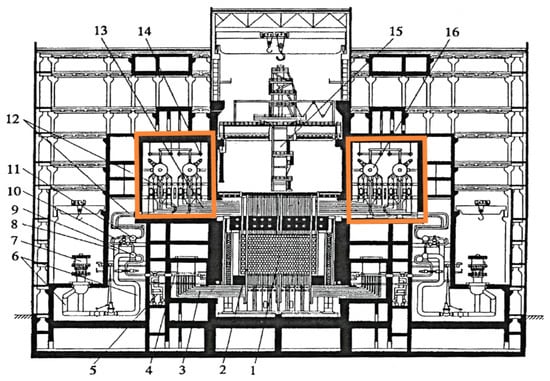
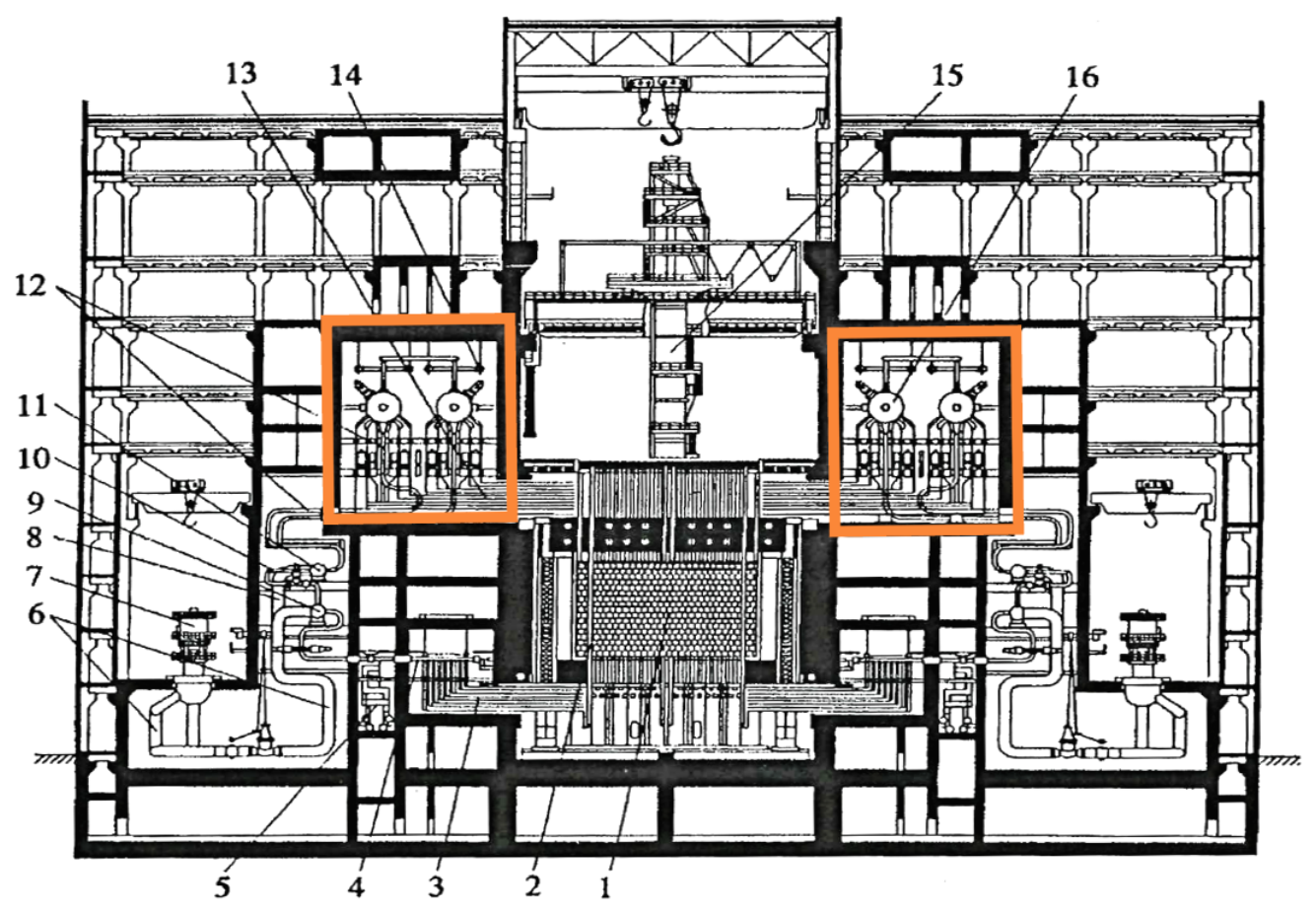
Two drum separator rooms are located above the reactor core room; each room contains two drum separators (Figure 1). Steam drums are part of the main circulation circuit (MCC), made of two loops. Each loop has two separator drums that separate the steam from the steam-water mixture. The steam is directed to turbines, and the water fraction is sent through the pipes to the main circulation pump, pressure header, and pipes, leading to fuel channels. The channels generate a steam-water mixture, which is sent back to the steam drum separators. The drums have three functions: separate steam from water, mix separated water with feedwater, and store coolant for the MCC.
Figure 1.
General view of NPP with RBMK-1500 reactor: 1, graphite stack; 2, fuel channel; 3, bottom water piping; 4, group distribution header; 5, emergency core cooling pipes; 6, MCP pressure pipes; 7, main circulation pump; 8, MCP suction pipes; 9, pressure header; 10, bypass pipes; 11, suction header; 12, downcomers; 13, steam and water pipes; 14, steam pipes; 15, refuelling machine; 16, drum separator [24], Reproduced with permission from K. Almenas, A. Kaliatka, E. Ušpuras, Source Book Ignalina RBMK-1500; published by Lithuanian Energy Institute, 1998.
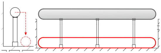
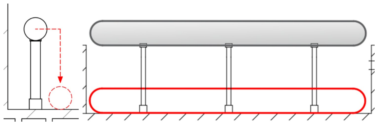
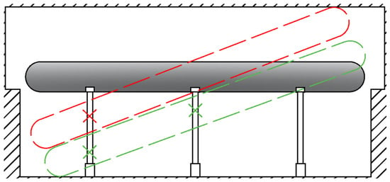
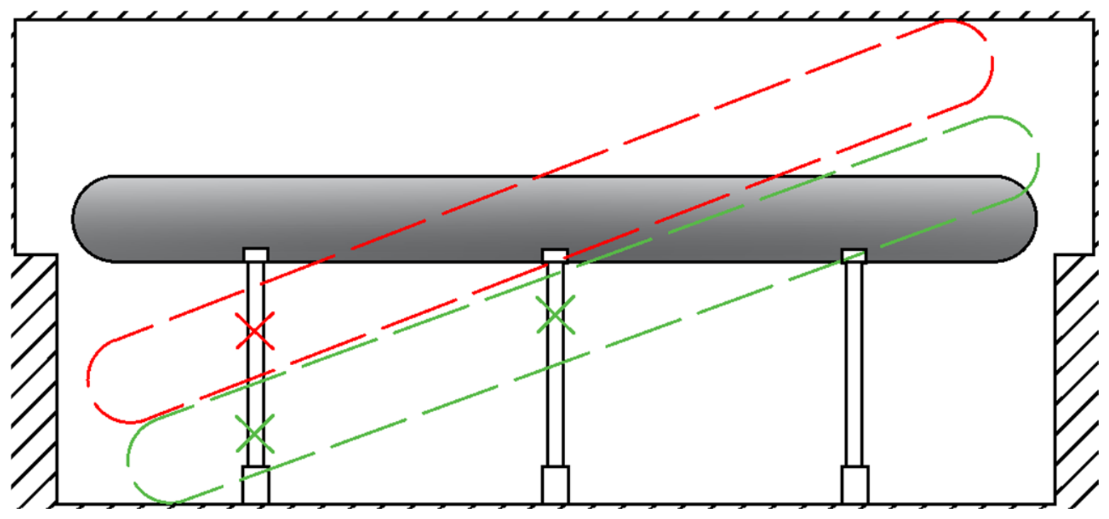
A drum drop hypothetical scenario was investigated to analyse possible orientations of the steam drum separator during dismantling operations (Figure 2). Red contours in Figure 2 illustrate hypothetical horizontal fall in the steam drum separator room. Because of the size of the room and minimal space for drums to move, only a horizontal fall seems possible (Figure 3). During decommissioning, large equipment may accidentally strike and knock over a column supporting the drum separator. Due to weight distribution, one end of the drum may strike the ceiling as shown in red contour. The impact force in this case will not be as detrimental as a horizontal fall. Another scenario could involve two fallen columns, which would cause localised impact, marked in green. However, due to debris from fallen columns and one still supporting column, the impact force would not be as great as during a horizontal fall.
Figure 2.
Hypothetical horizontal fall of drum separator.
Figure 3.
Drum separator room and limited space for drums to move.
The drum was assumed to fall while maintaining an approximately horizontal position, impacting the concrete floor along its lateral surface. This case represents a loss of support or slippage during disassembly, where the component maintains its axial alignment before the impact.
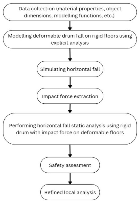
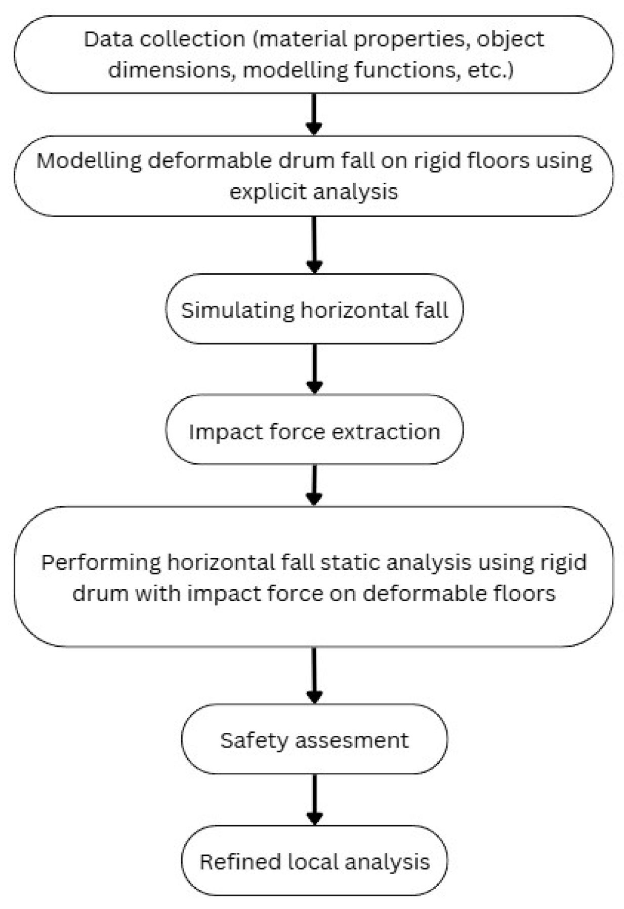
It was assumed that the drum was falling from a height of 8 m, which is around the typical steam drum separator installation height above the floor in RBMK-type reactor facilities [24]. The drum is approximately 33 m long, 2.8 m wide, with 0.115 m wall thickness. The weight of the drum is 261.94 tonnes. The analysis was conducted following a structured approach (Figure 4). Relevant data and parameters were collected, including material properties, component dimensions, and modelling assumptions.
Figure 4.
Analysis workflow of the study.
Then a deformable drum was modelled in explicit dynamic analysis to simulate a horizontal fall onto a rigid floor. The peak force was extracted and used for the following simulations assessing the building reinforced concrete floor’s stress values using a rigid drum falling onto a deformable floor meshed with shell elements. The refined local analysis, using a hybrid model of shell and solid elements, was performed for a deeper analysis of the results of an impact. The reason why the explicit solver was chosen, and later the implicit solver, is because of their solving equations. For the Abaqus implicit solver (static analysis), each time step solves a large nonlinear system of equations, but when there are nonlinearities such as plasticity, large deformation, or contact, the solver uses the Newton–Raphson method, which solves equations to ensure all forces and displacements are in equilibrium. This solver is stable and allows larger time steps but requires more computational effort. The Abaqus explicit solver (dynamic analysis) uses central difference methods that calculate motion directly based on known values of forces and accelerations. It uses small time steps and is built for fast events such as crashes or explosions [25]. While dynamic analysis enables a more detailed representation of the time-dependent structural response, simplified static approaches based on peak impact force are often used for preliminary safety assessments, as such analyses are less complicated, faster to execute, require less input data and, in some cases, can even result in higher structural response values [26].
Model Assumptions and Simplifications
It must be acknowledged that, due to limitations of the data, some simplifications had to be accepted:
- Due to lack of publicly attainable data, all components, such as drum separator, concrete slab and steel reinforcement, were modelled assigning only elastic properties, obtained from the literature;
- The calculated velocity of the falling drum from 8 m is 12.5 m/s, but rounded up to 13 m/s, due to approximate calculations of the drum fall height. The rounded-up value produces a higher impact force; therefore, investigating a more severe case of the falling heavy equipment covers the possible misjudgement of the exact fall height;
- The contact between the drum and the concrete floor slab was defined as “hard” and normal contact with frictionless tangential behaviour, due to lack of available information;
- The building structure was modelled according to the publicly available literature. As no information on the reinforcement of the walls was found, it was omitted in the model; only the reinforcement of the steam drum separator room floor was modelled;
- As the stiffness of the building structures further away from the drum separator room was unknown, the fully bounded boundary conditions were assigned to all outer edges of the model.
The above-mentioned assumptions and simplifications of the model do not allow a complete assessment of global building damage because important structural information is unavailable. The further analysed FEM models do not incorporate concrete damage mechanisms and, therefore, do not evaluate possible concrete cracking, crushing, tensile softening, etc., which potentially could overestimate the strength of the analysed structure. However, the quantitative effect of such assumptions and simplifications of the model remains unknown.
3. Analysis and Results
3.1. Impact Force Determination
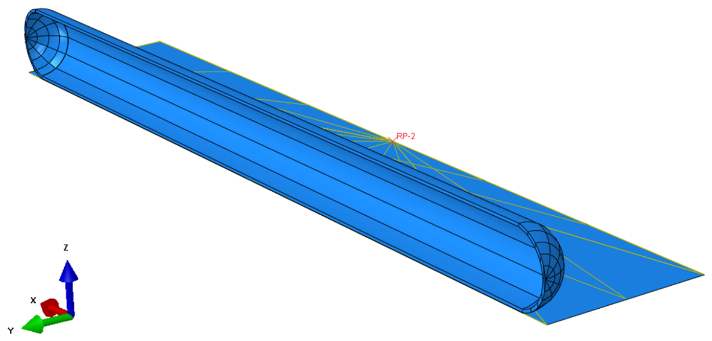
A finite element (FE) model was developed using ABAQUS 6.11 software [25]. The scenario was investigated by modelling two components—a deformable drum meshed with solid elements and a rigid ground meshed with shell elements (Figure 5).
Figure 5.
FE model of the horizontal drum impact on the rigid ground.
The steel 22K material properties, such as density, modulus of elasticity, Poisson’s ratio, and yield stress limit, were assigned to the drum, as presented in Table 1.
Table 1.
Steel drum’s material properties [24].
To save computational time, only half of a drum along its lateral direction was modelled, which is placed close to the rigid shell plane. For this simulation, an explicit solver was chosen, since it calculates dynamic equilibrium for nodal calculations (1) [25]:
where ü—the total nodal accelerations, M—nodal mass matrix, P—external applied forces, l—internal applied forces, t—time.
ü(t) = M−1(P(t) − l(t))
As a result of the calculation, an impact force in the Z direction was measured at a reference point placed on the shell plane. Surface-to-surface contact was applied, with the shell plane acting as the master surface and the relevant surfaces of the drum separator as the slave surface. The drum was assigned an initial velocity corresponding to gravitational acceleration, using Formula (2):
where v—velocity (m/s), g—acceleration of free fall (m/s2), h—fall height (m).
The initial velocity of the falling drum from 8 m is 12.5 m/s, but it was intentionally rounded up to 13 m/s to cover the possible slight miscalculations of the drum fall height.
The kinetic energy of a body with a mass of 261.94 tonnes moving at 13 m/s is approximately 22.13393 MJ.
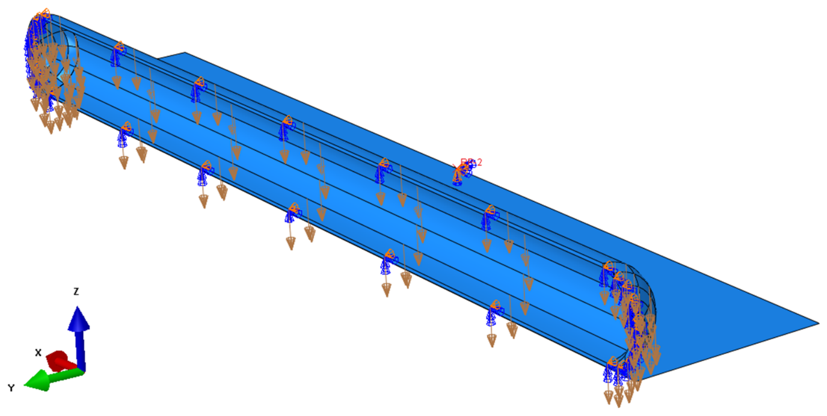
The symmetry boundary conditions were applied to the cut face of the model which is at the mirror plane parallel to the global XZ plane and passing through the axis of the drum. Another fixed boundary condition was applied at the RP point of the rigid shell plane (Figure 6). Blue arrows indicate rotational constrains around the X and Z axes; the brown arrows show direction of applied velocity; orange arrows indicate a constrained displacement in the Y direction.
Figure 6.
Boundary and load conditions of a drum.
The drum part was meshed using C3D8R finite elements, i.e., the eight-node linear brick elements with reduced integration and hourglass control, while the shell plane was assigned R3D4—the four-node 3D bilinear rigid quadrilateral finite elements. The drum and shell plane were meshed with local refinement in the impact zone to capture stress concentrations. The overall model has 152,462 nodes and 137,560 elements. The mesh sensitivity analysis data are shown in Appendix A.
3.2. Results of Impact Force Determination
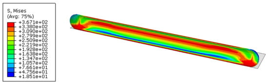
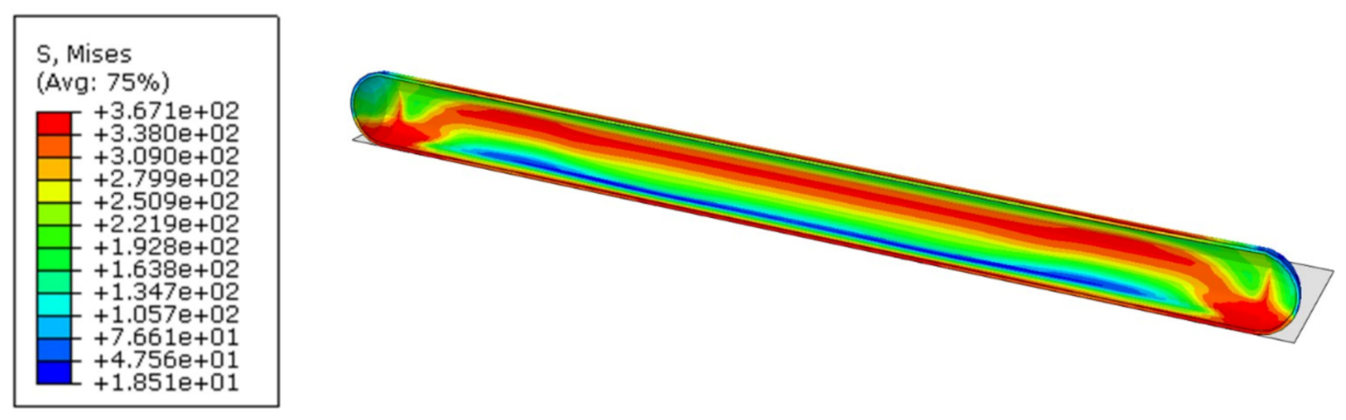
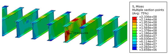
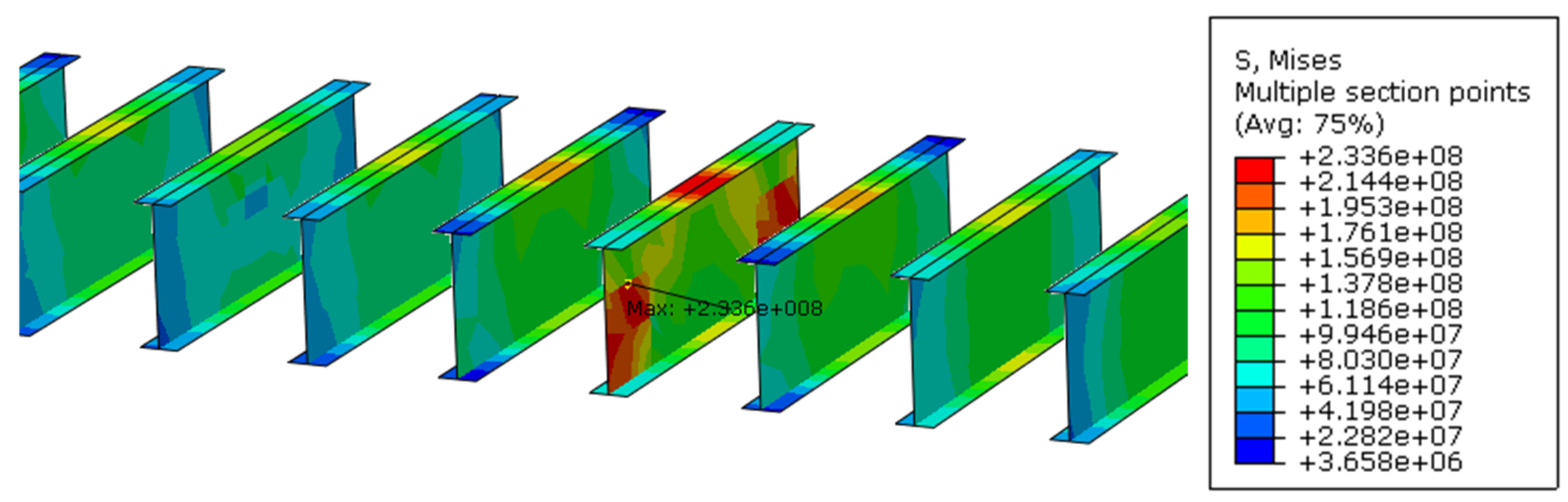
The results provide data on the maximum impact force during contact and the distribution of equivalent von Mises stresses within the drum structure. The drum exhibits slight deformation, with stress levels slightly exceeding yield stress (Table 1) (Figure 7).
Figure 7.
Mises stress distribution in the drum at impact to rigid ground, Pa.
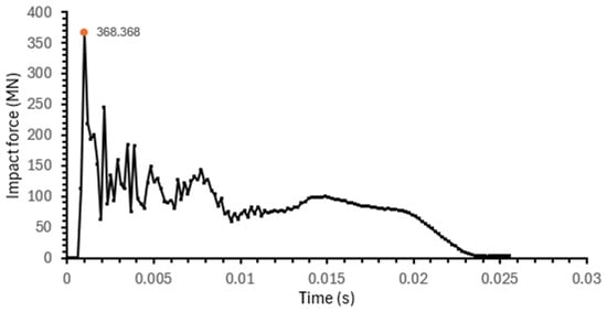
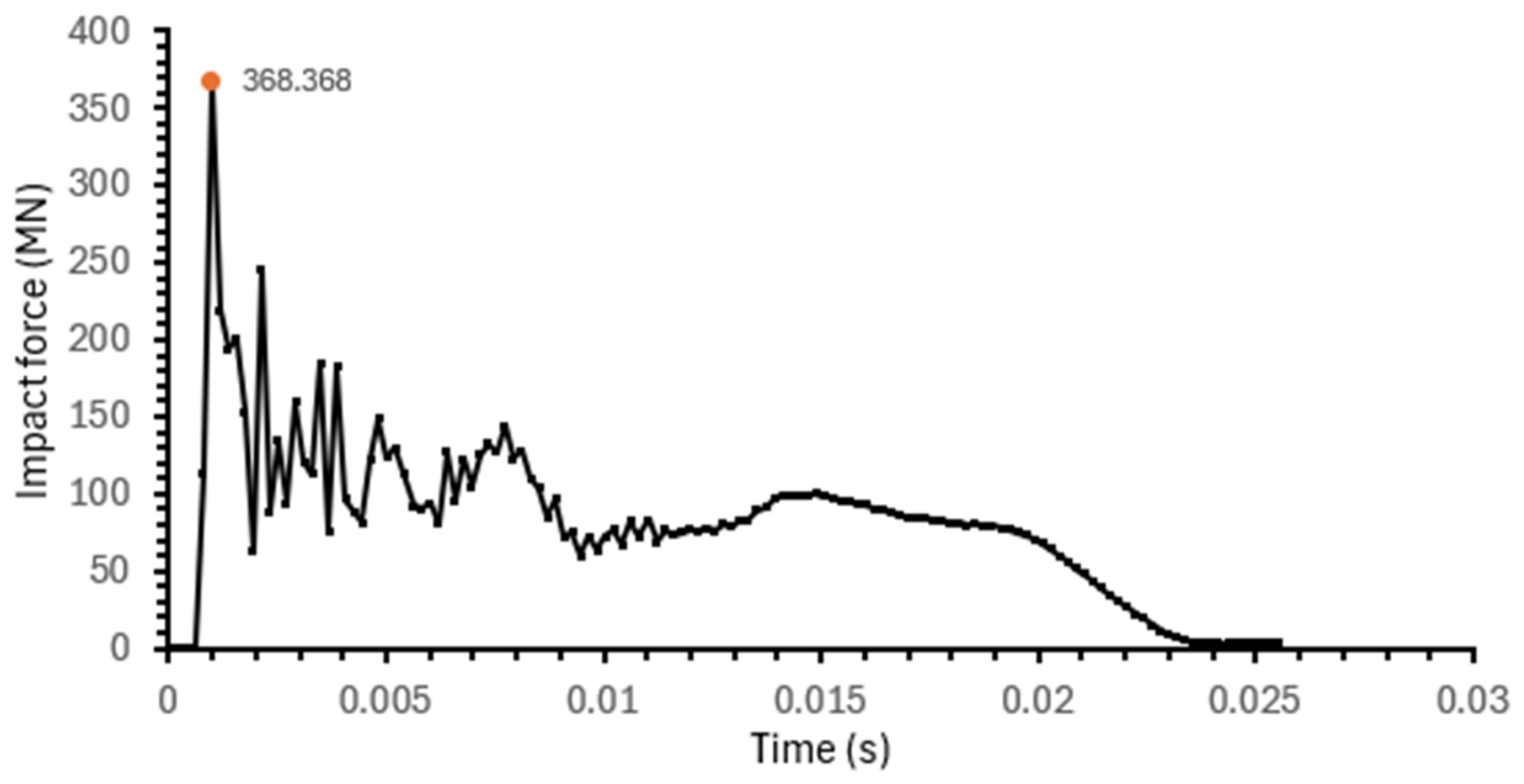
For the impact force determination, the data from the simulation are extracted and presented as a force–time graph in Figure 8. The highest peak of 368.368 MN impact force at a time stamp of 0.000966 s was selected for further structural response simulations. Fluctuations in the graph of the impact force past the peak value occur due to the shockwave travelling through the deformable body. No analogous analyses by other authors are available for comparison because the analysed object differs in terms of weight, shape, material, and impact speed. However, a somewhat comparable analysis is presented in the literature [27]. The authors analyse the drop of the metal cylinder, which has a height of 0.86 m and a mass of 3200 kg. The cylinder was dropped from a height of 16 m. The impact force on the rigid floor was 5.4 MN. Our analysed drum separator is around 82 times heavier. Multiplying the cylinder’s impact force by this factor would give an impact force of 442.8 MN. Taking into account that the cylinder was dropped from twice the height, our determined impact force is in the comparable region.
Figure 8.
Impact force–time graph in case of deformable drum impact to rigid ground.
3.3. Analysis of Impact to Reinforced Concrete Floor
The previous simulation of a deformable drum impacting a rigid ground showed no significant damage to the drum itself. The next analysis step is the static analysis using a rigid drum with an impact force on a deformable floor. In this analysis step, the drum is modelled using rigid shell elements, while reinforced concrete is modelled using deformable shell elements. The FE model of the facility is created using publicly available data [3,28,29,30,31,32].
The simulation scenario was analysed using a model of rigid shells, representing the steam drum separator, and a deformable concrete floor and wall assembly, modelled using shell elements. The concrete and steel structures were defined according to Table 2 from the literature [24,32,33,34]. Different densities of wall and floor were modelled according to the literature [32].
Table 2.
Reinforced concrete material properties.
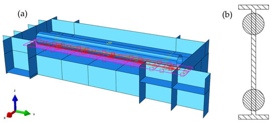
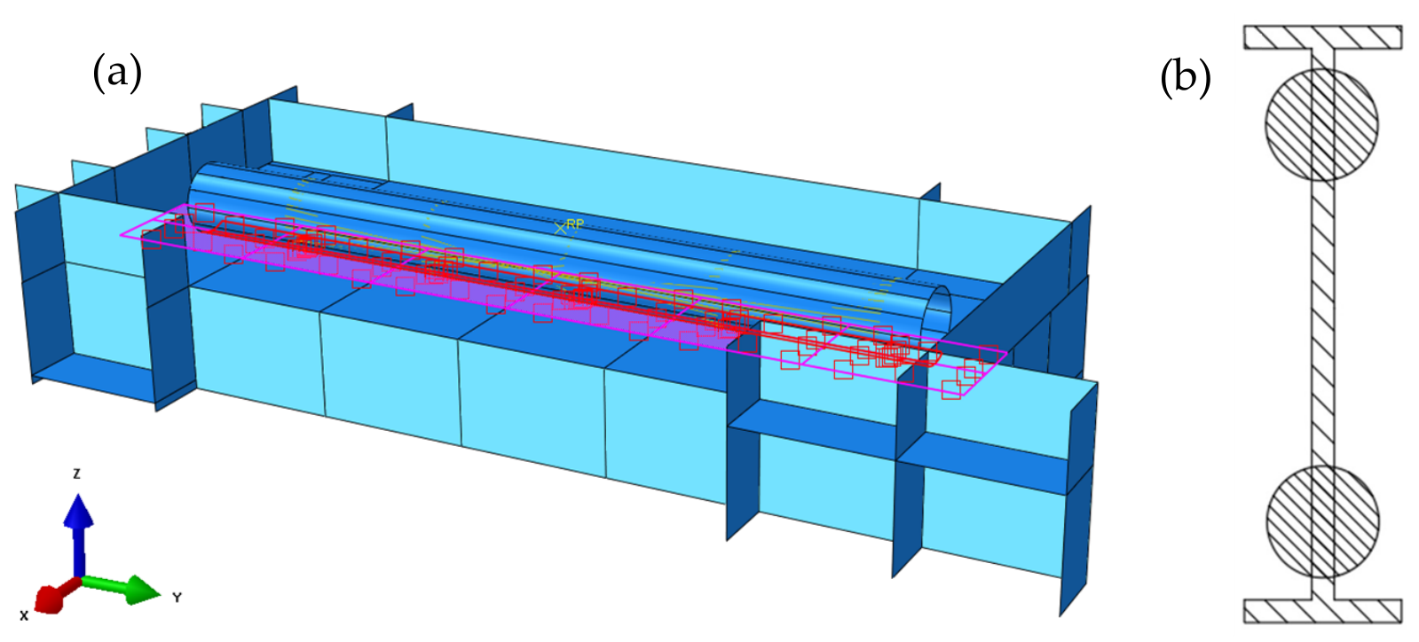
The floor model incorporated six reinforcement layers, where the outer layers represented steel rebar meshes and the intermediate layers represented H-section steel beams, spaced at one metre intervals. Owing to its thickness and dense reinforcement, the drum separator room floor exhibits good structural rigidity. In the numerical model, reinforcement defined by shell elements could only be represented as circular cross-section bars; therefore, each H-section beam was modelled as two parallel circular elements whose combined diameter corresponded to the equivalent cross-sectional area of the original H-profile. Graphical representation of how the H-profiles were replaced by two circular bars is presented in Figure 9b.
Figure 9.
FE model of the drum impact to the NPP facility’s concrete slab: (a) applied surface-to-surface contact interaction; (b) reinforcement modelling in shell elements.
The overall assembly characteristics were consistent with the configurations used in previous simulations. Using the simplified model, immovable boundary conditions were applied along the edges of the drum separator room to represent the continuity and stiffness of the surrounding building structure. A surface-to-surface contact interaction was applied to the corresponding drum and floor surfaces (Figure 9a). Contact properties were defined as frictionless tangential behaviour and “hard” normal behaviour. Red surface of the drum is primary and pink of the floor is secondary. The computational mesh consisted of S4R elements [25]—four-node doubly curved thin or thick shell elements with reduced integration, hourglass control, and finite membrane strains.
The model contains 219,356 elements and 219,657 nodes. The mesh sensitivity analysis data are shown in Appendix B. The simulation was performed using a standard implicit solver, ensuring numerical stability and convergence for static loading conditions. The drum was idealised as a rigid body by applying a kinematic coupling constraint, connecting the inner surface of the shell model to a reference point. The corresponding impact force was then applied to this reference point to represent the external loading. The simulated impact scenario provided insight into the stress distribution and structural response of the reinforced concrete floor and embedded reinforcement under different fall configurations of the steam drum separator.
3.4. Analysis Results of the Drum Impact to the Reinforced Concrete Floor
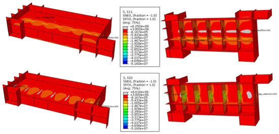
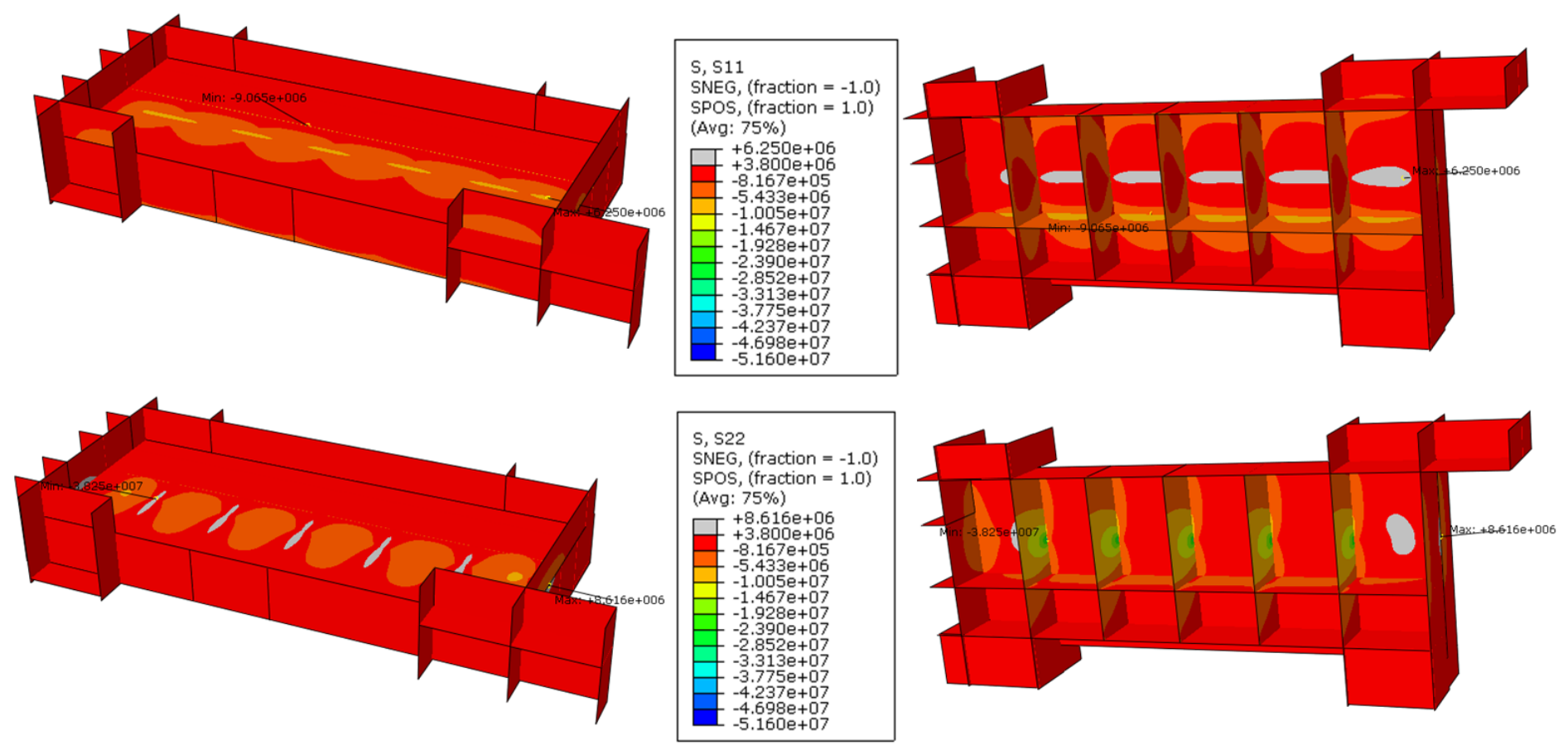
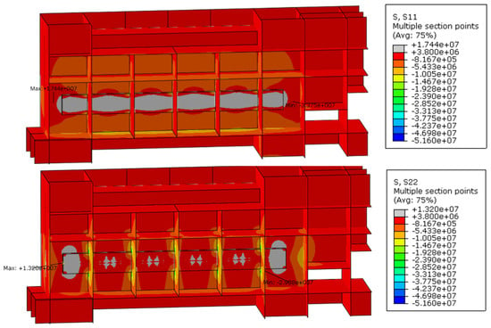
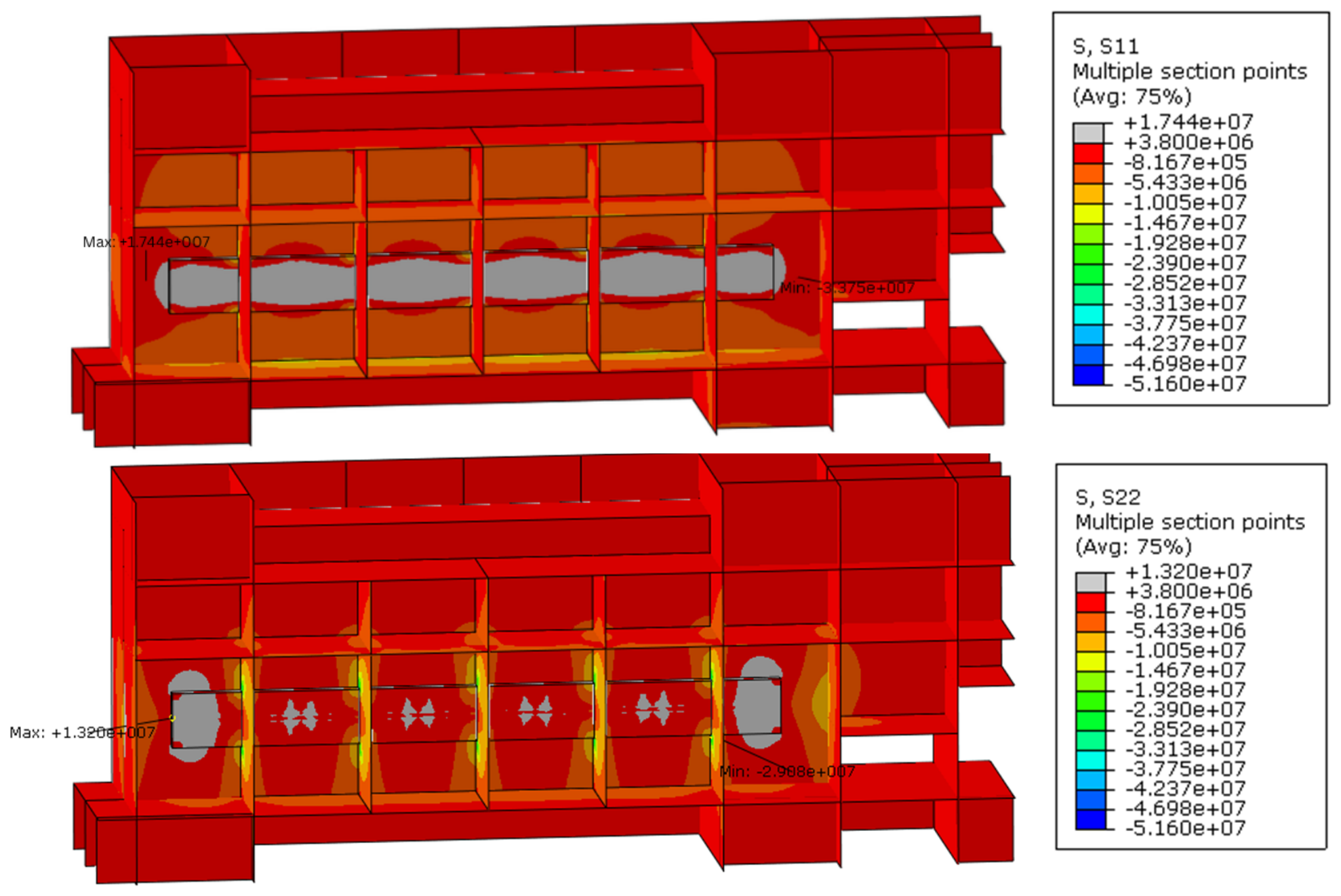
The analysis results are presented in Figure 10. The concrete has different ultimate strengths in tension and compression; therefore, the equivalent stress cannot be used for adequate evaluation of its structural integrity. Hence, stress distribution in the concrete structure is shown using stress components (S11, S22, and S33). The positive value of the stress component represents the tension loading, and the negative value represents the compression loading. The stress components of the elements in the model are with the assumptions established by the software [35,36]. S11, S22, and S33 represent normal stresses in the respective directions of the shell. S11 and S22 are stress components perpendicular to each other but coincident with the shell element surface. The exact direction depends on the orientation of the shell element; e.g., the S11 direction matches the global X-axis, and the S22 direction coincides with the global Y-axis for a steam drum separator room floor. According to the results, the upper concrete layer primarily absorbed the initial impact loads, causing compressive stress, i.e., negative stress values, to form in the reinforced concrete, while tensile stresses, i.e., positive stress values, tend to form in the lower regions of the concrete floor slab. Stress limits were defined to simplify the interpretation of results when stresses exceeded the material’s ultimate strength. Values exceeding the material’s strength limits are shown in grey for tensile or black for compression. Otherwise, legend indicates the highest stress value as a strength limit. These limits were used in all subsequent figures where stress distribution in concrete is shown. In Figure 10, the grey colour shows the stress values greater than the ultimate tensile strength of the concrete (Table 2), i.e., potential areas of the reinforced concrete slab that might be cracked due to impact force. Under impact load, the stress from the reinforced concrete floor spreads to the supporting walls of the underlying room. However, the level of stress in the walls is lower than the compressive strength of the concrete (Table 2). Also, it needs to be noted that, due to a lack of data, reinforcement was modelled only for the floor of the steam drum separator room. In this simplified model, other concrete structures had no modelled reinforcement.
Figure 10.
S11 (corresponds to the global X-axis in the floor slab) and S22 (corresponds to the global Y–axis in the floor slab) stress distribution in the concrete structure due to the steam drum separator impact, Pa.
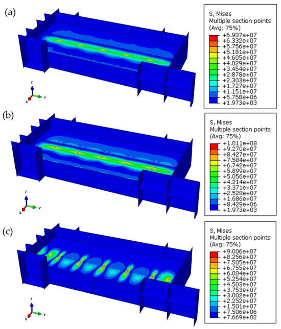
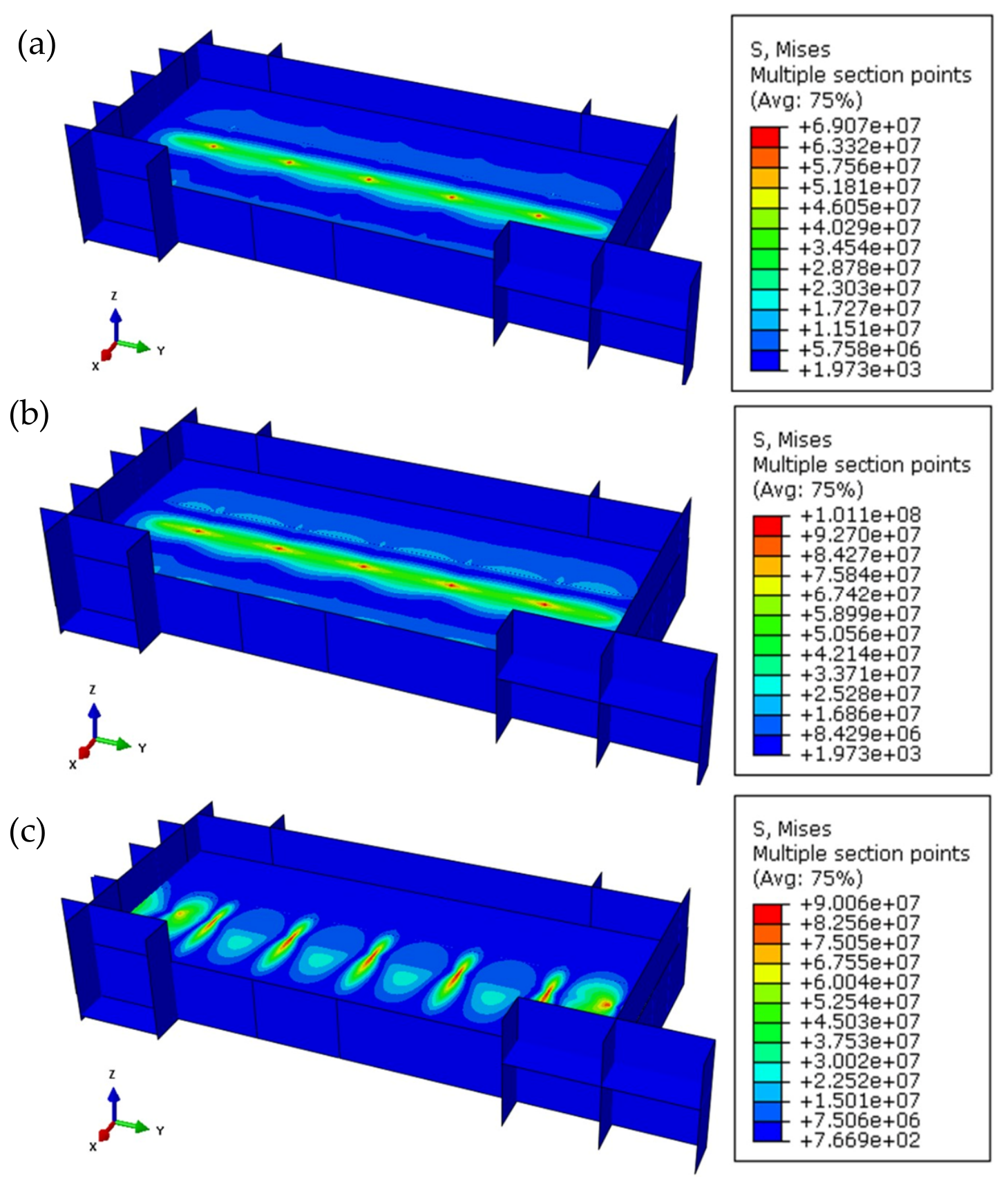
The reinforcement layers exhibited slight deformation yet remained within acceptable limits, with stresses not exceeding the yield threshold of the rebar material (Table 2) (Figure 11).
Figure 11.
Mises stress distribution in reinforcement layers: (a) top outer reinforcement mesh; (b) bottom outer reinforcement mesh; (c) inner reinforcement representing H-bars, Pa.
However, because shell elements do not provide through-thickness stress distribution, potential concrete cracking and reinforcement stress values cannot be fully resolved in this model. Also, the shell model does not allow for modelling the correct concrete reinforcement geometry. Therefore, an additional analysis was conducted using a hybrid modelling approach to more accurately characterise local damage and stress transfer mechanisms.
3.5. The Detailed Analysis of Horizontal Fall
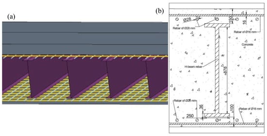
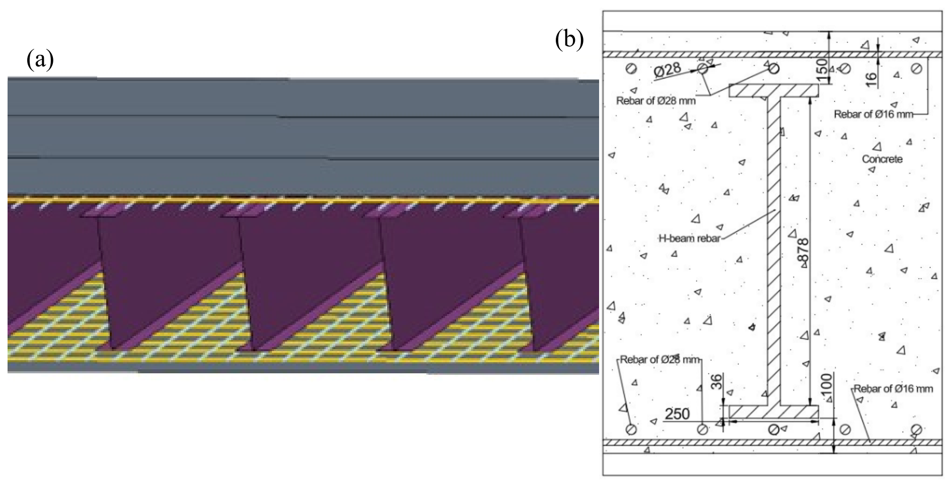
An additional detailed simulation was performed to examine the behaviour of the concrete floor and rebars during the impact. To capture the localised stress distribution within the structural floor, a segment of 1.2 m thickness of concrete slab was modelled using three-dimensional solid elements (grey) and embedded rebars represented by wire elements (yellow and cyan) and H-beams (purple) using shell elements (Figure 12a).
Figure 12.
Concrete slab with reinforcement: (a) FE model; (b) drawing.
While the use of shell elements in the primary model allowed for efficient analysis of global deformation and stress patterns, it did not provide sufficient information for evaluating through-thickness stress gradients or the detailed behaviour of reinforcement within the concrete. Accordingly, a hybrid assembly was developed, representing the RBMK-1500 reactor facility with shell elements for the global structure and a detailed solid element insert in the impact zone. The insert included shell-modelled H-beams (0.95 × 0.25 × 0.036 m) and embedded rebars of 0.028 m and 0.016 m diameter to reproduce realistic reinforcement conditions (Figure 12b). The interaction between reinforcing bars and the surrounding concrete was modelled using an embedded region constraint. Using this approach, the concrete structure is defined as the host region, while the steel reinforcement is assigned as the embedded region. This constraint enforces compatibility between the degrees of freedom of the reinforcement and the surrounding concrete elements, effectively representing a fully bonded interface and preventing any relative slip between the two materials.
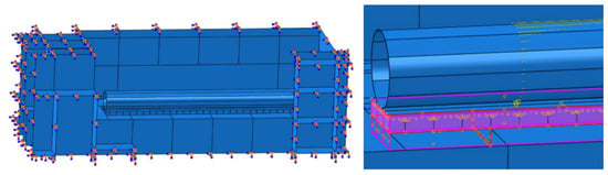
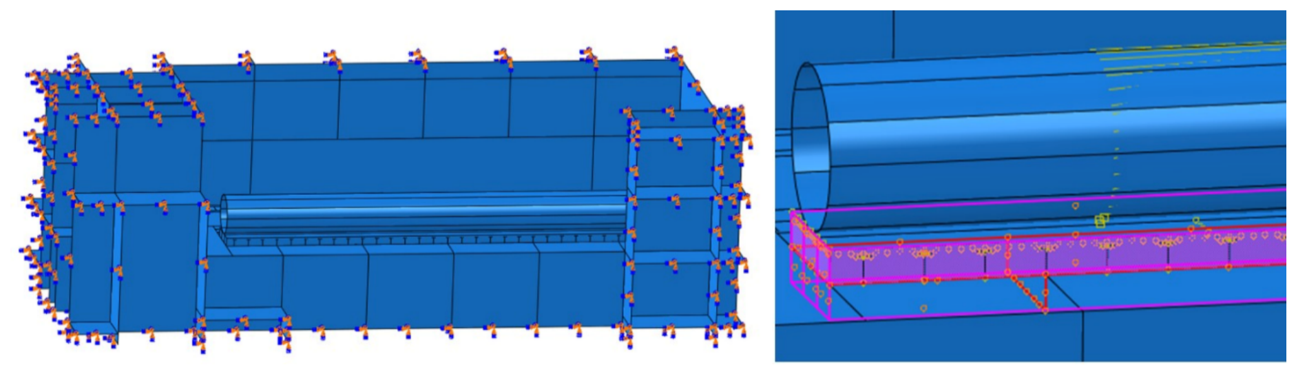
A concrete slab with reinforcement was connected to the rest of the assembly using a shell-to-solid coupling constraint (Figure 13). Primary red shell room’s edges are coupled with secondary pink surface of solid slab. In some articles, it is suggested that another shell element/body, a fictitious shell [8], or adding transitional elements [35] should be used, so that stresses and displacement would be transferred as efficiently as possible. Abaqus, however, already has a shell-to-solid coupling, well explained by K. W. Shim et al. [9], which automatically distributes shell kinematics to solid nodes, and adding an additional layer or elements would create artificial stiffness, double constraints and stress at the interphase. The steam drum separator, modelled as a cylindrical rigid shell structure, was positioned parallel to the floor and just above the floor surface. A concentrated external force was then applied to simulate the impact load at the moment of contact. The static, implicit analysis was conducted to simulate this impact.
Figure 13.
Boundary conditions and shell-to-solid constraint of the hybrid model.
3.6. The Detailed Model Results and Discussion
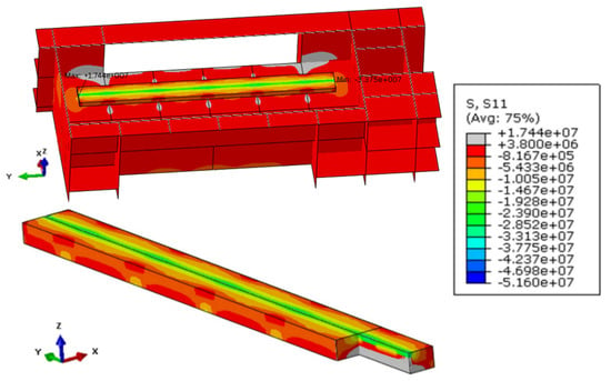
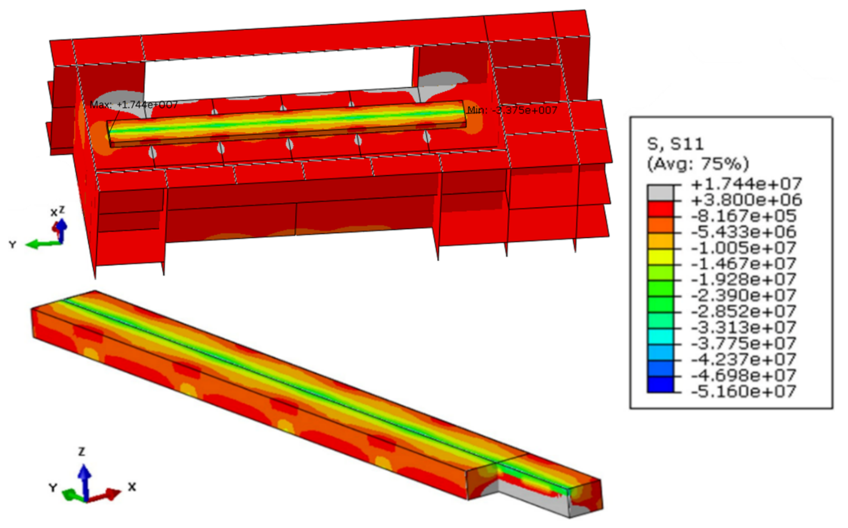
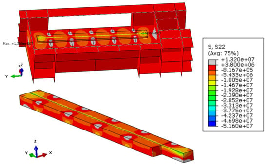
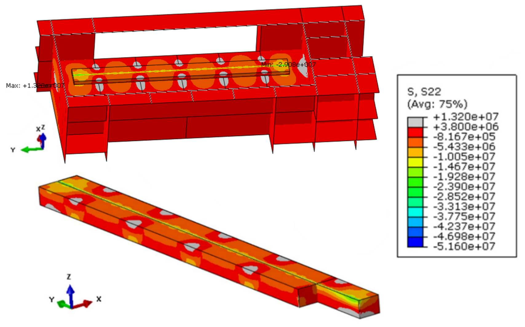
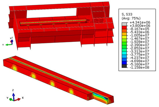
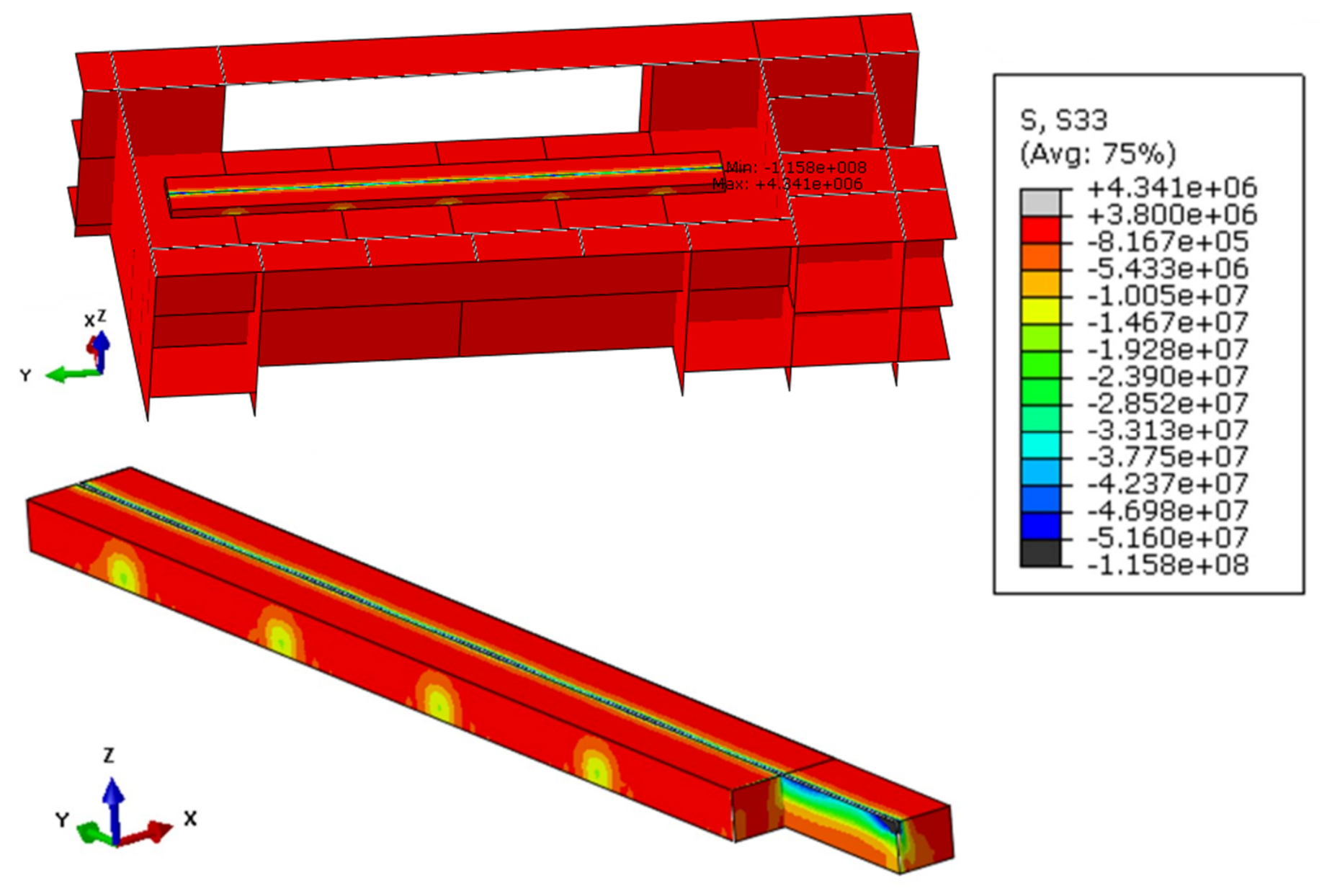
The horizontal impact scenario analysed with the hybrid solid–shell model revealed a better understanding of local stress distribution. The concrete in the direct impact zone exhibited stress levels surpassing its tensile strength in the S11 and S22 directions (Figure 14 and Figure 15) and surpassing compressive stress levels in the S33 direction (Figure 16), indicating possible cracking of the concrete in most top and bottom layers.
Figure 14.
S11 stress distribution in the concrete structure (corresponds to the global X-axis in the floor slab), Pa.
Figure 15.
S22 stress distribution in the concrete structure (corresponds to the global Y-axis in the floor slab), Pa.
Figure 16.
S33 stress distribution in the concrete structure (corresponds to the global Z-axis in the floor slab), Pa.
The stress extended into the supporting walls located directly below and adjacent to the impact point (Figure 17). As mentioned in the previous chapter, the reinforcement was modelled only in the steam drum separators room floor slab. According to this simplified model, stress in the walls is below the tensile and compressive strength of the concrete (Table 2).
Figure 17.
S11 and S22 stress distribution in concrete structure (bottom view), Pa.
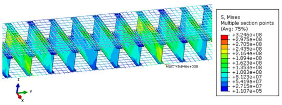
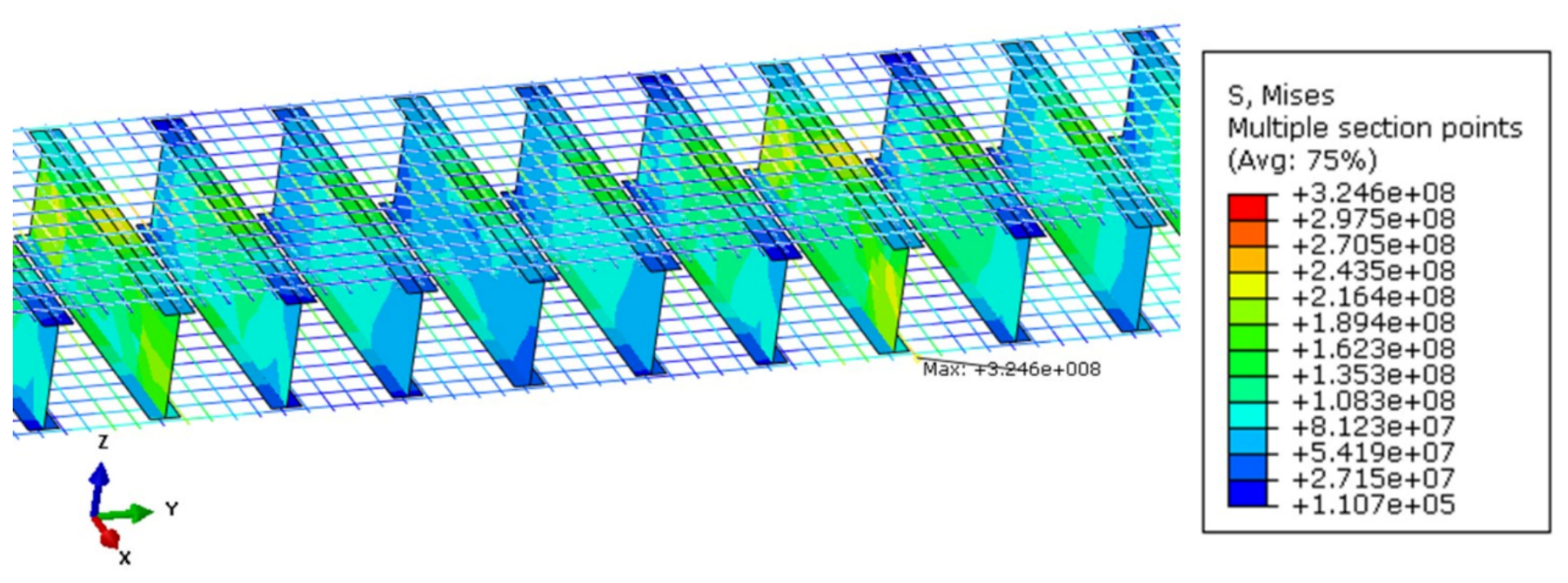
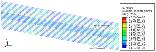
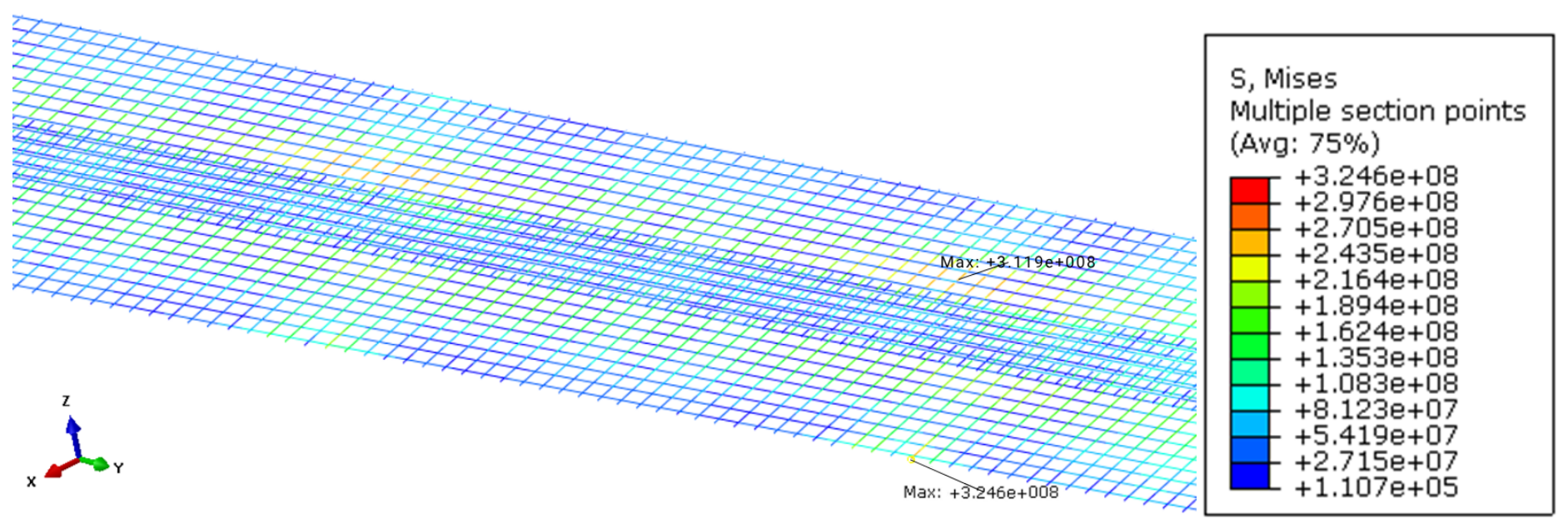
Reinforcement elements were subjected to stress, yet they do not exceed their yield strength limit that would lead to plastic deformation (Table 2) (Figure 18, Figure 19 and Figure 20).
Figure 18.
Stress distribution in steel reinforcement, Pa.
Figure 19.
Stress distribution in steel H-beams, Pa.
Figure 20.
Stress distribution in steel outer reinforcement, Pa.
These findings of the hybrid model show the concrete slab areas where determined stresses exceed ultimate limits in tension and compression; however, it also shows that stresses in all reinforcement layers are below the yield strength of the metal.
Based on this simplified model, the horizontal drum impact scenario may produce some structural damage and poses some safety risks. Nonetheless, the dismantling of RBMK facilities should be thoroughly planned to avoid such an event.
It needs to be noted that the present model does not explicitly simulate progressive cracking or crushing of concrete using damage models. In this study, structural safety was evaluated by comparing computed stresses with materials’ ultimate strength limits. This approach allows identification of regions where stresses exceed material capacity, providing an estimate of potential damage zones (Table 3). Table 3 presents the maximum stress values determined in the concrete and reinforcement of shell and hybrid models. It also presents the demand-to-capacity (D/C) ratio, defined as the ratio of the maximum determined stress to the ultimate strength of concrete and the ratio of the maximum Mises equivalent stress to the yield strength of the steel.
Table 3.
Materials’ limit stresses, obtained stresses and demand-to-capacity ratio.
4. Results and Discussion
In this study, the fall of heavy equipment and the impact on the reactor building’s steam drum separator room floor was analysed. The FEM models were developed for impact force determination, stress distribution in reinforced concrete structures due to impact load, and a hybrid model containing shell and solid elements was developed for a detailed evaluation of reinforcement geometry and more accurate stress distribution determination. The peak force of 368 MN obtained from explicit simulation was used as the loading condition for the local structural integrity evaluation. The results show that the steam drum separator’s horizontal impact exceeds the adopted tensile strength limit for concrete, indicating a potential cracking region, which was evaluated by comparing computed stress components with the characteristic compressive and tensile limits of the concrete (Table 3). The fall of the rigid drum onto the deformable building floor resulted in stresses of 6.25 MPa and 8.61 MPa in the X and Y directions, respectively, indicating the potential for cracking in the upper concrete layers. The reinforcement experienced a maximum stress of 101.1 MPa, which remained below its yield strength. Based on the concrete tensile strength and reinforcement yield strength, the corresponding demand-to-capacity ratios were 1.64 and 2.26 for concrete in the X and Y directions, respectively, and 0.15–0.22 for the reinforcement. Regions where calculated stresses exceed these limits were interpreted as zones where cracking or local crushing would possibly occur. To further investigate the stress distribution, an additional local simulation was performed. The highest tensile stress in the concrete slab of the hybrid model meshed with solid elements in the X, Y, and Z directions, respectively, reached 17.44 MPa, 13.2 MPa, and 4.34 MPa, while the maximum compressive stress reached −115.8 MPa in the Z direction. The lower reinforcement experienced a maximum stress of 324.6 MPa, corresponding to a demand-to-capacity ratio of 0.73, while the upper reinforcement displayed maximum stress of 311.9 MPa with a 0.7 demand-to-capacity ratio, based on its yield strength.
It must be noted that the used FEM model demonstrates that, despite possible concrete cracking, the reinforcement remains intact. These findings highlight the importance of thorough planning of the dismantling process and controlled handling of the equipment during decommissioning in high-risk zones of RBMK reactors. The steam drum separator itself undergoes minor deformation as impact generates stress levels slightly above the yield limit in the drum separator’s body.
The study uses a simplified model and approach; however, it still provides valuable knowledge on hybrid modelling and the evaluation of stress distribution and magnitude in concrete and reinforcement. To obtain more accurate results, future work should use damage models for a more detailed investigation of concrete cracking, as the current approach only allows identification of the regions where stresses exceed material ultimate strength, providing an estimate of potential damage zones.
Author Contributions
Conceptualization, E.B.; Methodology, E.S. and R.J.; Software, E.S.; Validation, E.S. and R.J.; Formal Analysis, E.S. and R.J.; Investigation, E.S. and R.J.; Resources, E.B.; Writing—Original Draft Preparation, E.S.; Writing—Review and Editing, R.J. and E.B.; Visualisation, E.S.; Supervision, R.J. and E.B. All authors have read and agreed to the published version of the manuscript.
Funding
This research received no external funding.
Institutional Review Board Statement
Not applicable.
Informed Consent Statement
Not applicable.
Data Availability Statement
The raw data supporting the conclusions of this article will be made available by the authors on request.
Conflicts of Interest
The authors declare no conflicts of interest.
Appendix A
The results of the mesh sensitivity analysis of the FE model of the horizontal drum impact on the rigid ground are presented in Table A1 and Figure A1 and Figure A2.
Table A1.
Mesh sensitivity analysis results of drum impact to rigid ground model.
Figure A1.
Impact force vs. number of elements.
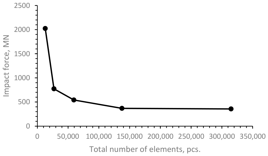
The difference in impact force between the models with mesh 1 and 2 is 62%, between 2 and 3 is 30%, and between 3 and 4 is 32%. The difference between the impact force of meshes 4 and 5 is only 3.25%, while mesh 5 contains almost twice as many elements as mesh 4. According to these results, mesh 4 was chosen for the analysis.
Figure A2.
Energy vs. time.
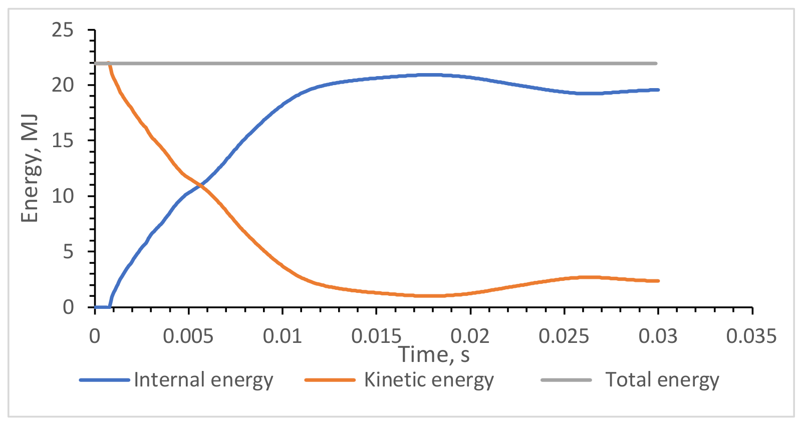
The decrease in kinetic energy is mirrored by an increase in internal energy, indicating that much of the initial kinetic energy is converted into internal energy through deformation and impact-related processes. The nearly constant total energy suggests that overall energy is approximately conserved during the simulation.
Appendix B
The results of the mesh sensitivity analysis of the FE model of the drum impact to the NPP facility’s concrete slab are presented in Table A2, Figure A3 and Figure A4.
Table A2.
Mesh sensitivity analysis results of drum impact to the NPP facility’s concrete slab model.
Figure A3.
Stress in concrete vs. number of elements.
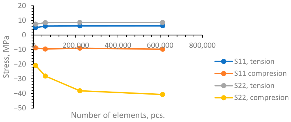
Figure A4.
Equivalent stress in reinforcement vs. number of elements.
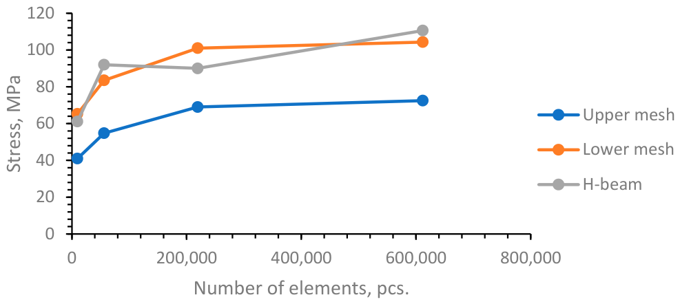
Results show that with an increase in the elements number the difference between the results decreases, and the difference between the results of models with mesh 3 and 4, while containing more than twice the number of elements, for concrete is less than 1% in tension, up to 8% in compression, outer mesh experiences about 5% for outer mesh, and up to 3.3% for lower mesh. Only H-beams show a chaotic trend due to changing of the maximum stress point location. According to the results, mesh 3 was chosen for the analysis.
References
- Jacques, M.; Räty, A.; Cabrerizo, J.A.R.; Daniska, D. European collaborations for safe and efficient dismantling: Digital twins, ontology and data exchange. EPJ Nucl. Sci. Technol. 2025, 11, 19. [Google Scholar] [CrossRef] [Scilit] [PubMed]
- Chapurlat, V. A contribution for dismantling of nuclear facilities: A functional pattern for dismantling operations and indicators design and management. EPJ Nucl. Sci. Technol. 2024, 10, 12. [Google Scholar] [CrossRef] [Scilit] [PubMed]
- Kaliatka, A.; Ušpuras, E. Heat removal from RBMK reactor core using non-regular means. Nucl. Eng. Des. 2019, 354, 110165. [Google Scholar] [CrossRef] [Scilit]
- IAEA: Country Statistics. Available online: https://pris.iaea.org/PRIS/CountryStatistics/CountryDetails.aspx?current=RU (accessed on 13 November 2025).
- Remeikis, V.; Grineviciute, J.; Duškesas, G.; Juodis, L.; Plukienė, R.; Plukis, A. Review of modeling experience during operation and decommissioning of RBMK-1500 reactors. I. Safety improvement studies during operation. Nucl. Eng. Des. 2021, 380, 110952. [Google Scholar] [CrossRef] [Scilit]
- Dundulis, G.; Petkevicius, K.; Uspuras, E.; Marchertas, A. Structural response analysis of the confinement system of the Ignalina nuclear power plant. Nucl. Eng. Des. 1999, 191, 75–81. [Google Scholar] [CrossRef] [Scilit]
- Remeikis, V.; Grineviciute, J.; Duškesas, G.; Juodis, L.; Plukienė, R.; Plukis, A. Review of modeling experience during operation and decommissioning of RBMK-1500 reactors. II. Radioactive waste management. Nucl. Eng. Des. 2021, 380, 111242. [Google Scholar] [CrossRef] [Scilit]
- Osawa, N.; Hashimoto, K.; Sawamura, J.; Nakai, T.; Suzuki, S. Study on shell–solid coupling FE analysis for fatigue assessment of ship structure. Mar. Struct. 2007, 20, 143. [Google Scholar] [CrossRef] [Scilit]
- Shim, K.W.; Monaghan, D.J.; Armstrong, C.G. Mixed Dimensional Coupling In Finite Element Stress Analysis. Eng. Comput. 2002, 18, 241–252. [Google Scholar] [CrossRef] [Scilit]
- Shen, J.; Chen, Z. Welding simulation of fillet-welded joint using shell elements with section integration. J. Mater. Process. Tech. 2014, 214, 2529. [Google Scholar] [CrossRef] [Scilit]
- Chen, W.; Deng, X. Performance of shell elements in modeling spot-welded joints. Finite Elem. Anal. Des. 2000, 35, 41–57. [Google Scholar] [CrossRef] [Scilit]
- Karalis, D.G. Increasing the efficiency of computational welding mechanics by combining solid and shell elements. Mater. Today Commun. 2019, 22, 100836. [Google Scholar] [CrossRef] [Scilit]
- Gou, G.; Yang, Y.; Chen, H. An ICME Approach for Optimizing Thin-Welded Structure Design. Engineering 2014, 6, 936–947. [Google Scholar] [CrossRef]
- Peeters, M.; Santo, G.; Degroote, J.; Van Paepegem, W. Comparison of Shell and Solid Finite Element Models for the Static Certification Tests of a 43 m Wind Turbine Blade. Energies 2018, 11, 1346. [Google Scholar] [CrossRef] [Scilit]
- Bojórquez, J.; Bojórquez, E.; Leyva, H.; Barraza, M. Failure Probability-Based Optimal Seismic Design of Reinforced Concrete Structures Using Genetic Algorithms. Infrastructures 2024, 9, 164. [Google Scholar] [CrossRef] [Scilit]
- Yu, H.; Jeong, D.Y. Impact dynamics and puncture failure of pressurized tank cars with fluid–structure interaction: A multiphase modeling approach. Int. J. Impact Eng. 2015, 90, 12. [Google Scholar] [CrossRef] [Scilit]
- Dou, W.; Zhang, L.; Chen, G.; Stichel, S. A boundary-condition-transfer method for shell-to-solid submodeling and its application in high-speed trains. Int. J. Mech. Sci. 2020, 177, 105542. [Google Scholar] [CrossRef] [Scilit]
- Krueger, R.; O’Brien, T.K. A shell/3D modeling technique for the analysis of delaminated composite laminates. Compos. Part A Appl. Sci. Manuf. 2001, 32, 25–44. [Google Scholar] [CrossRef] [Scilit]
- Zappino, E.; Carrera, E. Multidimensional Model for the Stress Analysis of Reinforced Shell Structures. AIAA J. 2017, 56, 1647–1661. [Google Scholar] [CrossRef] [Scilit]
- Pachla, F.; Kowalska-Koczwara, A.; Tatara, T.; Stypuła, K. The influence of vibration duration on the structure of irregular RC buildings. Bull. Earthqu. Eng. 2019, 17, 3119. [Google Scholar] [CrossRef] [Scilit]
- Betti, M.; Vignoli, A. Numerical assessment of the static and seismic behaviour of the basilica of Santa Maria all’Impruneta (Italy). Constr. Build. Mater. 2011, 25, 4308. [Google Scholar] [CrossRef] [Scilit]
- Peña, F.; Lourenço, P.B.; Mendes, N.; Oliveira, D.V. Numerical models for the seismic assessment of an old masonry tower. Eng. Struct. 2010, 32, 1466. [Google Scholar] [CrossRef] [Scilit]
- Bazaras, Z.; Timofeev, B. Effect of Long-Term Thermal Influence on Mechanical Properties of Welded Joints for Carbon Steels used in Power Engineering. In Steam Generator Systems: Operational Reliability and Efficiency; Uchanin, V.N., Ed.; InTech: Rijeka, Croatia, 2011; pp. 75–100. ISBN 978-953-307-303-3. [Google Scholar] [CrossRef] [Scilit] [PubMed]
- Almenas, K.; Kaliatka, A.; Ušpuras, E. IGNALINA RBMK-1500: A Source Book; Lithuanian Energy Institute: Kaunas, Lithuania, 1998; pp. 40–80. ISBN 9986-492-35-1. [Google Scholar]
- ABAQUS/Standard User’s Manual, Version 6.11. 2011. Available online: http://130.149.89.49:2080/v2016/books/usb/default.htm?startat=book01.html (accessed on 15 May 2026).
- Sadique, M.R.; Iqbal, M.A.; Bhargava, P. Aircraft-structure interaction study for the assessment of the reaction-time response of nuclear containment structure. Structures 2022, 39, 866–881. [Google Scholar] [CrossRef] [Scilit]
- Babilas, E.; Ušpuras, E.; Rimkevičius, S.; Dundulis, G.; Vaišnoras, M. Safety assessment of low-contaminated equipment dismantling at nuclear power plants. Sci. Technol. Nucl. Install. 2015, 2015, 650810. [Google Scholar] [CrossRef] [Scilit]
- CIA Worldwide Report: Nuclear Development and Proliferation. USSR State Comittee Report on Chernobyl Nuclear Power Plant Accident. 1986. Available online: https://www.cia.gov/readingroom/docs/CIA-RDP09-00997R000100260001-0.pdf (accessed on 6 November 2025).
- Mitchell, W. Design Features of the Soviet RBMK-1000/Chernobyl-4 Reactor: A Report Prepared for the Advisory Committee on Reactor Safeguards [Interactive]. 1986. Available online: https://www.nrc.gov/docs/ML2020/ML20202G309.pdf (accessed on 5 November 2025).
- Dundulis, G.; Kačianauskas, R.; Markauskas, D.; Stupak, E.; Stupak, S.; Šliaupa, S. Reanalysis of the floor response spectra of the Ignalina Nuclear Power Plant Reactor Building. Nucl. Eng. Des. 2017, 324, 260–268. [Google Scholar] [CrossRef] [Scilit]
- Alzbutas, R.; Dundulis, G. Probabilistic Assessment of Structural Integrity. Axioms 2024, 13, 154. [Google Scholar] [CrossRef] [Scilit]
- Dundulis, G.; Kulak, R.F.; Marchertas, A.; Uspuras, E. Structural integrity analysis of an Ignalina nuclear power plant building subjected to an airplane crash. Nucl. Eng. Des. 2007, 237, 1503–1512. [Google Scholar] [CrossRef] [Scilit]
- Chernobyl Object Shelter (Sarcophagus): Dosimetry Mapping Project. Available online: https://sredmash.wixsite.com/obektukritie/about (accessed on 5 November 2025).
- Database of Steel and Alloy (Marochnik). Available online: https://www.splav-kharkov.com/en/e_mat_start.php?name_id=29 (accessed on 5 November 2025).
- Işık, E.; Harirchian, E.; Arkan, E.; Avcil, F.; Günay, M. Structural Analysis of Five Historical Minarets in Bitlis (Turkey). Buildings 2022, 12, 159. [Google Scholar] [CrossRef] [Scilit]
- Dávila, C.G. Solid-to-shell transition elements for the computation of interlaminar stresses. Comput. Syst. Eng. 1994, 5, 193–202. [Google Scholar] [CrossRef] [Scilit]

Disclaimer/Publisher’s Note: The statements, opinions and data contained in all publications are solely those of the individual author(s) and contributor(s) and not of MDPI and/or the editor(s). MDPI and/or the editor(s) disclaim responsibility for any injury to people or property resulting from any ideas, methods, instructions or products referred to in the content. |
© 2026 by the authors. Licensee MDPI, Basel, Switzerland. This article is an open access article distributed under the terms and conditions of the Creative Commons Attribution (CC BY) license.