


Abstract
Tunnel construction in completely weathered granite strata with rich water storage is potentially risky and can lead to catastrophic hazards without proper engineering measures. This study investigates the mechanisms of key surface dewatering parameters—well spacing, dewatering depth, and well–tunnel distance—on the groundwater-level field, stress field, and displacement field, as well as their control efficacy with respect to tunneling-induced deformation, based on three-dimensional finite element analysis and field monitoring. The results demonstrate that reducing well spacing (from 22 m to 7 m) promotes a progressively continuous and gentle drawdown funnel. The maximum surface settlement induced by dewatering to 20 m below the ground surface increases from 3.5 cm to 5.0 cm when the well spacing changes from 22 m to 7 m, while excavation-caused deformation decreases and the surface settlement trough evolves from discrete “crest-shaped” patterns to a continuous “U-shaped” profile, accompanied by an increase in total settlement. Increased dewatering depth enhances the effective stress in the soil but also significantly expands the extent of consolidation settlement and shear strain. The well–tunnel distance critically influences the effectiveness of dewatering in controlling the tunnel-adjacent zone. Surface dewatering, through a synergistic “pressure relief–consolidation” mechanism, systematically improves the geotechnical properties of strata by both reducing hydrostatic loads and enhancing soil resistance. Based on derivations from discrete simulated cases, a recommended dewatering design is proposed for similar water-rich weak-stratum tunnel projects, with well spacings of 11 m to 15 m and dewatering depths extending to approximately the tunnel invert level. These recommendations provide a reference for dewatering design and construction control in related engineering contexts comparable to the present case study.
1. Introduction
With the accelerating pace of global urbanization, urban land resources have become increasingly scarce. Exploiting underground space has consequently emerged as an inevitable strategy for addressing challenges such as urban traffic congestion, inadequate infrastructure, and mounting environmental pressures [1,2,3]. Tunnels and underground works, as core carriers for urban water resources regulation, transportation, and municipal infrastructure development, play an irreplaceable role in fostering sustainable urban development [4,5]. However, the design and construction of tunnel projects persistently confront severe challenges posed by complex geological conditions, dense urban environments, and stringent environmental protection requirements [6,7,8]. Particularly in highly built-up and environmentally sensitive areas, tunnel construction is often subject to multiple interrelated constraints: densely distributed aboveground structures, intersecting traffic arteries, intricate underground utility networks, and extremely limited working spaces. Engineering geological conditions are highly variable, frequently requiring tunnels to traverse adverse geological units such as soft soils, water-rich sand layers, weathered rock masses, and fault fracture zones, which are characterized by heterogeneous engineering properties and poor stability. Moreover, urban hydrogeological conditions are significantly influenced by human activities, with groundwater levels fluctuating frequently, further elevating construction risks. Under such unfavorable conditions, improper construction control can readily induce catastrophic events, including tunnel collapse, face instability, excessive surface settlement, and even water inrush and mud gushing [9,10,11,12]. Such incidents can not only jeopardize construction safety but also cause irreversible damage to the surrounding environment.
To date, numerous researchers have investigated dewatering and drainage measures and their effectiveness in tunnel design and construction within water-rich strata. Wang et al. [13] analyzed monitored changes in water content following tunnel excavation, elucidating the variation patterns of surrounding rock water content and the relationship between water content and surrounding rock stability. Wang and Luo [14] summarized the construction processes and methods, as well as technical parameters, for dewatering under such stratum conditions based on the three-tier dewatering method (vertical deep wells + advanced vacuum deep boreholes + light well points) employed at a railway. Huo et al. [15] used a coupled seepage–stress numerical model and field monitoring data to investigate surface settlement, surrounding soil deformation, and mechanical responses in water-rich loess tunnels. They found that under dewatering and reinforcement conditions, tensile stresses developed in the soil layers at the middle partition wall and middle partition plate, indicating an unstable state that necessitates enhanced monitoring of these structural components during construction. Wang et al. [16] summarized the failure modes and causative mechanisms of sandy dolomite strata and proposed construction control countermeasures, including hazard source identification, pressure relief through water release, hazard source reinforcement, and low-disturbance excavation, for managing water and mud inrush disasters in tunnels in sandy dolomite formations based on the analysis of regional geology, laboratory microscopic observations, and physical model tests. Wang et al. [17] proposed a surface ultra-deep pumping-well dewatering method based on the field practice at a tunnel site, where three deep wells were successfully installed and pumping experiments were carried out.
In China’s economically developed and highly urbanized coastal regions, such as the Pearl River Delta and the Yangtze River Delta, urban underground engineering faces even more formidable challenges. These areas are underlain by extensive thick sequences of recent soft deposits, granite residual soils, and completely to highly weathered rock formations [18]. When tunnels are constructed in such water-rich strata, the geomaterials are prone to softening and drastic strength reduction upon water exposure, readily inducing a series of severe geohazards, including face instability, large-scale surrounding rock deformation, and water/mud inrushes. The Bao’an District of Shenzhen, as a quintessential highly urbanized area, exhibits particularly complex engineering geological conditions. The site consists of granite residual soils and completely weathered granites that are extremely prone to softening and disintegration and possess exceptionally poor self-stability upon water contact. Granite residual soils and completely weathered granites, as special geomaterials, display engineering properties that are highly sensitive to water occurrence [19,20,21]: while they can maintain a certain structural strength under natural or slightly moist conditions, the inter-particle cementation is rapidly lost upon water exposure, leading to abrupt strength degradation and near-complete loss of self-supporting capacity [22,23]. The intricate interplay between these extremely complex geological conditions and the highly sensitive, heavily constrained urban environment poses a major challenge to the safe, efficient, and environmentally sound construction of tunnel projects.
Surface dewatering serves as an economical, efficient, and proactive stratum reinforcement technique for tunnel engineering. In theory, it lowers the groundwater table to increase the effective stress of surrounding strata and reduce seepage pressure, which fundamentally stabilizes the stratum environment and guarantees the smooth progress of tunnel excavation. In contrast, conventional in-tunnel grouting with small pipes exhibits prominent inherent deficiencies when applied in water-rich weathered granite strata. The complex porous and fractured geological characteristics of this stratum easily lead to severe slurry loss during grouting construction, resulting in unsatisfactory water stoppage and stratum reinforcement effects that often fail to meet design specifications. Comparatively, surface dewatering has distinct advantages, including ground-based safe operation, high construction efficiency, and reliable stratum treatment effects. Nevertheless, the recommended design of dewatering schemes—including reasonable arrangement of well spacing, dewatering depth and well–tunnel distance—to realize efficient stratum dewatering, ensure excavation safety, and minimize dewatering-induced consolidation settlement, as well as its superposition deformation with subsequent excavation disturbance, remains a key technical bottleneck to be solved in practical engineering.
Based on the tunnel project constructed in typical water-rich weathered granite strata, this study established a three-dimensional fluid–solid coupled numerical model to investigate the regulatory effects of core dewatering parameters (well spacing, dewatering depth, and well–tunnel distance) on groundwater-level distribution, stratum stress response and displacement evolution. It quantitatively evaluated the reinforcement effectiveness and associated environmental effects of different dewatering schemes in suppressing tunnel excavation deformation. The novelty of this study can be summarized as three-fold: (i) targeted hydro-mechanical investigation focusing on water-rich completely weathered granite, a typical water-sensitive geomaterial widely distributed in different areas throughout the world; (ii) parametric evaluation of three key surface-dewatering design parameters (well spacing, dewatering depth, and well–tunnel horizontal distance); (iii) detailed analysis of superposed ground deformation originating both from dewatering-triggered consolidation and subsequent tunnel excavation disturbance. This work further clarifies the synergistic “pressure relief–consolidation” mechanism of surface dewatering and provides practical parameter ranges balancing excavation safety and additional ground settlement for comparable projects. The findings provide a recommended reference for dewatering design, construction safety control, and environmental protection in tunnel projects under similar complex hydrogeological and urban environmental conditions.
2. Research Background
2.1. Project Overview
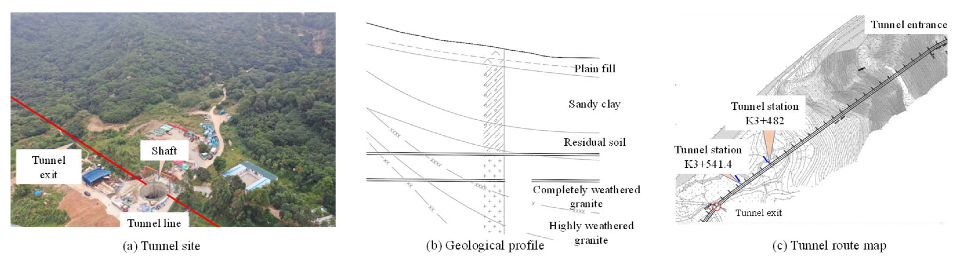
The tunnel is part of a water conveyance project in Shenzhen, China. The tunnel has a cross-section of 5.5 m (width) × 6.6 m (height), with primary and secondary lining thicknesses of 24 cm and 50 cm. An overview of the tunnel project is shown in Figure 1. The tunnel lining system was designed according to the New Austrian Tunneling Method (NATM) principle, adopting a composite lining configuration. The primary support consists of systematic rock bolts, steel reinforcement mesh, shotcrete, and steel ribs, while the secondary lining is cast-in-place reinforced concrete. For the Class V surrounding rock section, an enhanced primary support system supplemented by advanced pre-grouting with micropipes for pre-reinforcement is specified in the design. To address the challenges posed by water-rich strata, the original design scheme incorporated supplementary surface dewatering measures at the shaft and shallow-buried sections.
Figure 1.
Tunnel project overview.
2.2. Engineering Geology and Hydrogeology
The portal sections and shallow-buried sections of the tunnel under investigation are predominantly granite residual soils and completely weathered granites (locally exhibiting water-rich sand-layer characteristics), which are classified as Class V surrounding rock with extremely poor self-stability. The tunnel outlet section is located in a valley terrain adjacent to a water reservoir. Approximately 250 m of the tunnel body traverses completely weathered granite and residual soil strata, with an overburden thickness of about 20 m. The entire tunnel section lies below the groundwater table, imposing substantial pressures on drainage and stability control during construction. The tunnel traverses a mountain range, characterized by relatively massive topography and steep natural slopes, typically around 30° in inclination. The maximum burial depth of the tunnel invert is approximately 112.5 m.
- (1)
- Stratigraphy
The strata in the tunnel traversing zone exhibit distinct vertical stratification. From top to bottom, they are as follows:
Quaternary residual soil (Layer ③): predominantly gravelly, clayey soil; a weathering residue of granite; characterized by loose structure and susceptibility to softening upon water contact.
Completely weathered granite (Layer ④-1): original rock structure largely damaged, mineral components significantly altered, core samples in soil-like state with low strength.
Highly weathered granite (Layer ④-2): original rock structure mostly damaged, mineral components obviously altered, core samples in fragmental or short columnar state with uneven strength.
Slightly weathered granite (Layer ④-4): intact rock mass with unaltered structure and high strength, constituting a competent bearing stratum.
The tunnel traverses a typical soil and soil–rock transition zone. The surrounding rock is predominantly Layer ③ residual soil and Layer ④-1 completely weathered granite. This section is classified as Class V surrounding rock, exhibiting granular to cataclastic structures, low overall strength, and poor self-stability. Without timely and effective support after excavation, collapse is highly prone to occur.
- (2)
- Hydrogeological Conditions
Groundwater at the site consists primarily of pore water in the unconsolidated overburden and bedrock fissure water in the bedrock fractures. Hydraulic connectivity exists between these two types. According to the geotechnical investigation report, the permeability coefficients (k) of the residual soil and completely weathered granite range from approximately 3.0 × 10⁻⁵ cm/s to 6.0 × 10⁻⁴ cm/s. However, under the abundant rainfall infiltration in the Shenzhen area and lateral recharge from adjacent surface water bodies, this layer can still sustain a persistently water-rich environment during construction, posing a serious threat to tunnel works. Observation data from the investigation period indicate a relatively shallow groundwater table, which is near the ground surface. Groundwater activity not only reduces the effective stress and shear strength of the geomaterials through pore-water pressure but can also induce seepage failure (e.g., suffusion and quicksand) under mechanical excavation disturbance, drastically accelerating the softening and rheological deformation of the surrounding rock—this constitutes one of the foremost challenges in tunnel construction at this site.
- (3)
- Major Engineering Geological Problems
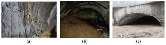
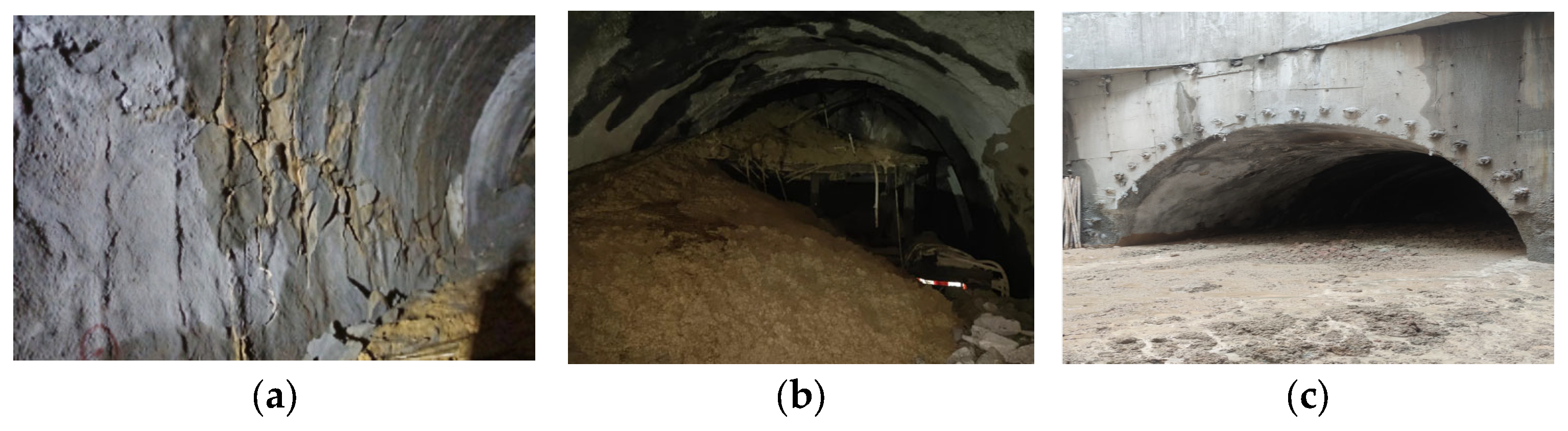
Extremely poor surrounding rock stability: Completely weathered granite and residual soil can maintain temporary stability under natural or slightly moist conditions. However, upon exposure to water-rich environments, their cohesion (c) and internal friction angle (φ) undergo rapid attenuation, resulting in extremely short self-standing time of the tunnel walls. Without immediate closure after excavation, large-scale collapse is highly likely to occur (See Figure 2).
Figure 2.
Main problems encountered during tunnel construction. (a) Fracture of primary support. (b) Collapse of tunnel face. (c) Water and mud inrush.
High risk of water and mud inrush: Under water-rich conditions, the soil mass ahead of the tunnel face, driven by hydrodynamic pressure, may suddenly discharge water and sand/mud along pre-existing microfractures or construction-induced weak planes. Such events can instantaneously inundate the working face, posing a severe threat to personnel and equipment safety.
Stringent surface settlement control requirements: The burial depth of this tunnel section varies considerably, with localized shallow-buried segments. Excessive tunnel convergence deformation or ground loss can propagate to the surface, potentially adversely affecting surface vegetation, planned construction land, and existing underground utility lifelines, necessitating high-level environmental protection.
2.3. Problem Analysis
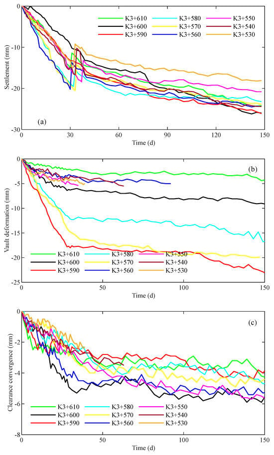
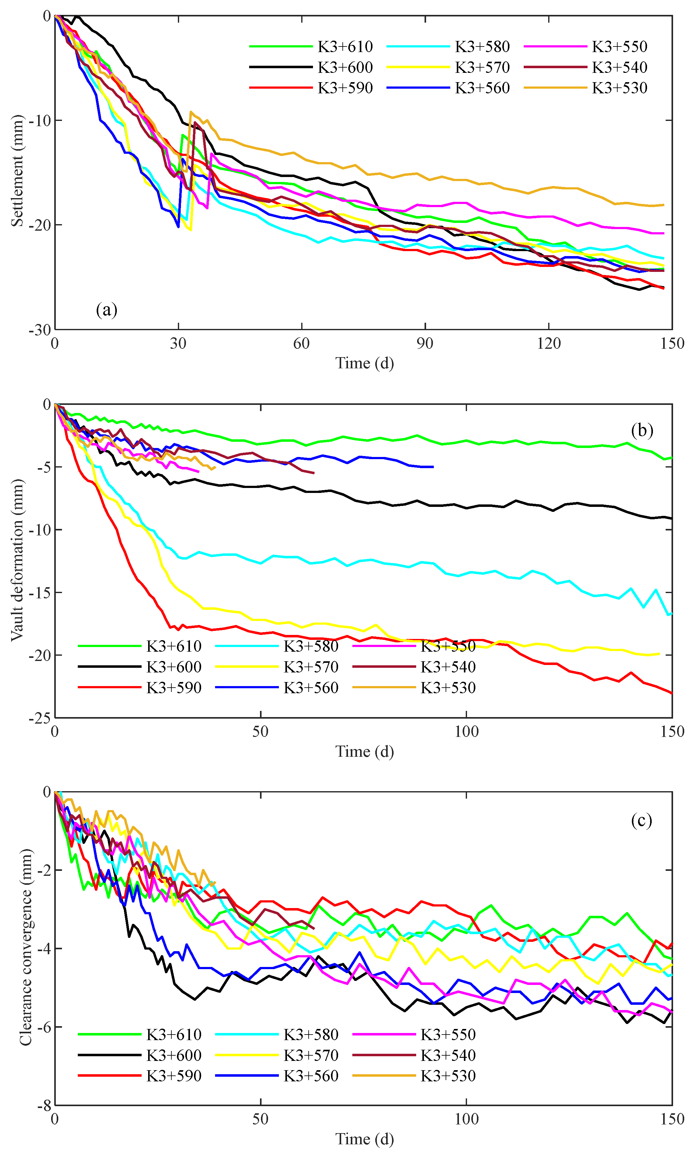
Figure 3 presents the field monitoring results for surface settlement, crown settlement, and clearance convergence at typical cross-sections during tunnel construction. Since the commencement of monitoring, deformation data from all monitoring sections have exhibited significant and continuously developing trends. Analysis of the deformation time-history curves reveals distinct stages: an initial phase of extremely rapid deformation, followed by a persistent growth phase with a reduced but still ongoing rate. Particularly during the early monitoring period (approximately the first 100 days), the average surface settlement rate reached 2.4 mm/d, crown settlement exceeded 1.7 mm/d, and clearance convergence surpassed 0.7 mm/d. Such high deformation rates indicate extremely rapid stress release from the surrounding rock following excavation unloading, with the primary support system responding sensitively. More critically, the deformation rates did not exhibit an apparent convergence trend throughout the monitoring period, suggesting continued deterioration of surrounding rock stability with the potential for further instability or even failure. Additionally, the tunnel outlet is characterized by abundant groundwater, soft and easily deformable surrounding rock prone to collapse upon water contact, and difficulties in primary support installation. Therefore, to effectively control deformation development and ensure safety during the tunnel construction stage, there exists an urgent and engineering-necessitated need for systematic, active ground pre-reinforcement and support enhancement measures.
Figure 3.
Field monitoring results of tunnel deformation at different sections: (a) surface settlement; (b) clearance convergence; (c) crown deformation.
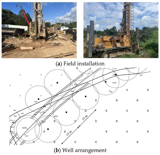
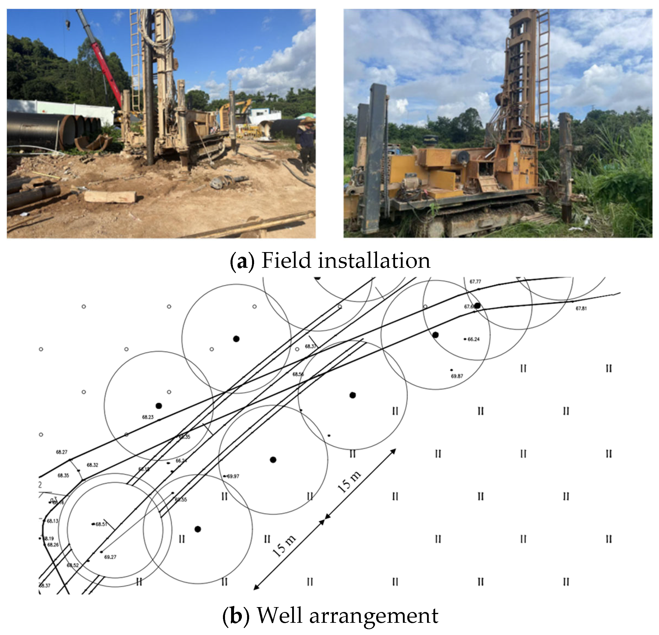
Conventional tunneling methods, when traversing such water-rich, completely weathered, weak granite strata, frequently encounter a trilemma of “difficult face stabilization, excessive support loading, and unacceptable surface settlement.” Relying solely on in-tunnel advanced support (e.g., advanced pre-grouting with micropipes) and enhanced primary support often results in high costs, complex construction procedures, and ultimately limited control effectiveness. Consequently, exploring an active and efficient ground pre-reinforcement method capable of fundamentally improving the physical and mechanical properties of the excavated geomaterials has become an urgent need for this project and similar engineering undertakings. Surface dewatering, as a promising deformation control measure (field installation of dewatering wells is shown in Figure 4), enhances the shear strength of the soil directly by lowering the groundwater table, thereby reducing pore-water pressure acting on the soil skeleton (i.e., increasing effective stress), while also eliminating or reducing seepage forces and improving face stability. However, the optimization of the specific dewatering scheme—including well spacing, dewatering depth, and well placement—to achieve effective stratum dewatering and safe excavation conditions while minimizing the consolidation settlement induced by dewatering itself and avoiding adverse superposition with excavation-induced settlement, remains a critical challenge requiring in-depth investigation in this study.
Figure 4.
Construction photograph of surface dewatering wells for the tunnel (a) and well arrangement (b).
3. Numerical Model
3.1. Model Description
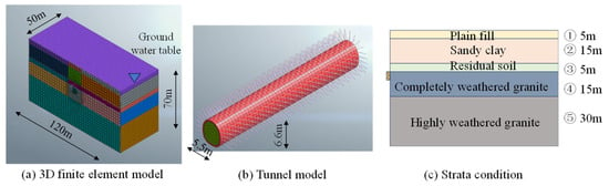
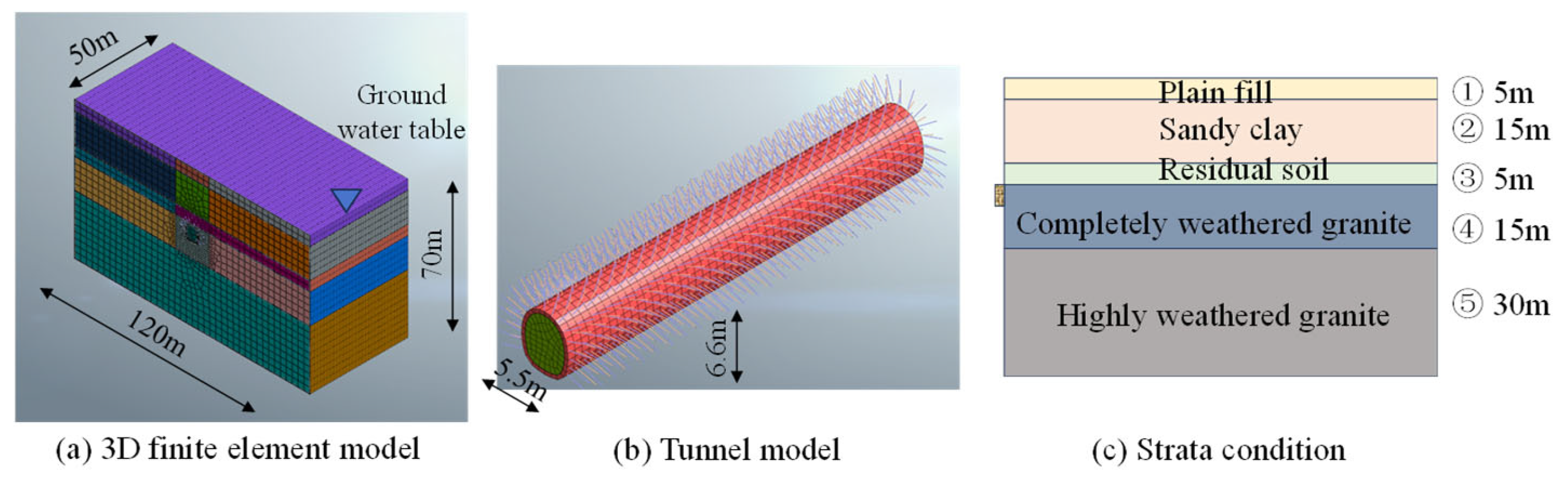
To conduct an in-depth investigation of the combined effects of surface dewatering and tunnel excavation on the water-rich highly weathered granite stratum, this study established a three-dimensional fluid–solid coupled numerical model using the finite element software Midas GTS NX, as shown in Figure 5. To eliminate the influence of boundary constraints on the simulated stress and displacement fields around the tunnel, the model was extended 60 m on each side from the tunnel centerline in the horizontal direction (perpendicular to the tunnel axis), yielding a total width of 120 m. In the longitudinal direction, a representative 50 m long section was modeled to capture the spatial effects of dewatering wells and tunnel excavation as well as the continuity of the stratum response. The top boundary of the model corresponds to the actual ground surface, while the bottom boundary extends to a sufficient depth below the weathered granite layer to ensure computational stability.
Figure 5.
Tunnel model and stratigraphic distribution.
The three-dimensional fluid–solid coupled model was established using Midas GTS NX. The model dimensions are width (X) × height (Z) × length (Y) = 120 m × 70 m × 50 m. Positive direction: X-axis = horizontal perpendicular to tunnel; Y-axis = tunnel longitudinal direction; Z-axis = vertical upward; model center sits on tunnel axis; horizontal half-width = 60 m, total width = 120 m. The model is centered on the tunnel axis, with 60 m extending to each side and the bottom boundary positioned below the highly weathered granite layer. The model comprises approximately 180,000 elements, predominantly hexahedral, with localized mesh refinement around the tunnel excavation contour, where the minimum element size is 0.5 m. A mesh-independence convergence test with three mesh densities (coarse: 110,000 elements; baseline: 180,000 elements; refined: 250,000 elements) was performed under the baseline dewatering case (well spacing = 15 m). The relative differences in maximum surface settlement are 3.2% and 2.7%, respectively. These three different mesh densities could satisfy the convergence requirement and do not deviate greatly in simulation results. The baseline mesh scheme with 180,000 elements is adopted in the present model as it achieves acceptable numerical accuracy and computational efficiency. Tunnel excavation was simulated using the “deactivation” of elements, while the primary support and secondary lining were modeled using the “activation” of plate elements. Dewatering wells were simulated by setting well boundary conditions with a pumping rate of 100 m3/d. The analysis time steps were divided into three stages: (1) initial in situ stress and seepage field equilibrium; (2) steady-state analysis of surface dewatering; and (3) sequential tunnel excavation and support (1 m advancement per step).
The numerical simulation in this study only targets the shallow buried portal valley segment of this tunnel, where the overburden thickness above the tunnel crown is approximately 20 m. The top boundary of the tunnel model coincides with the actual ground surface. The encountered strata from top to bottom are: fill (5 m), gravelly clay (15 m), residual soil (5 m), completely weathered granite (15 m), and highly weathered granite (30 m), as illustrated in Figure 5. The tunnel is located 20 m below the fill surface. For the overburden soils and completely to highly weathered rocks that undergo predominant plastic deformation, the Mohr–Coulomb elastoplastic constitutive model—widely adopted in geotechnical engineering with clearly defined physical parameters—was employed. The core strength parameters include cohesion (c) and internal friction angle (φ), while the deformation parameters include elastic modulus (E) and Poisson’s ratio (ν). The primary physical–mechanical parameters and permeability coefficients for each soil layer, derived from the site investigation report, are listed in Table 1.
Table 1.
Tunnel stratigraphic parameters.
The fully coupled seepage–stress procedure is adopted: pore-water pressure fields update iteratively together with mechanical stress–strain fields within each calculation step. The convergence tolerance is 1.0 × 10⁻⁸ per calculation increment. The initial geostatic stress field is generated under hydrostatic initial groundwater conditions before dewatering simulation. For groundwater boundaries: lateral model boundaries are set as constant-head boundaries corresponding to the initial hydrostatic water level; the ground surface is assigned as a zero-flux seepage boundary. Each excavation step simulates a 1 m advance with a calculation time duration of 1 day. The primary support has an elastic modulus, E = 32 GPa and Poisson’s ratio ν = 0.25.
Boundary conditions were configured as follows: the bottom boundary was fixed in all directions (Ux = Uy = Uz = 0); the four lateral boundaries were restrained in the normal direction (i.e., Y-direction displacement constrained on the X-Z plane and X-direction displacement constrained on the Y-Z plane), with vertical displacement permitted to simulate the influence of infinitely distant strata; the top surface was a free boundary with no displacement constraints to simulate actual ground surface deformation.
3.2. Simulation Cases
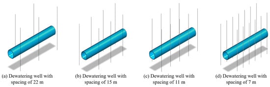
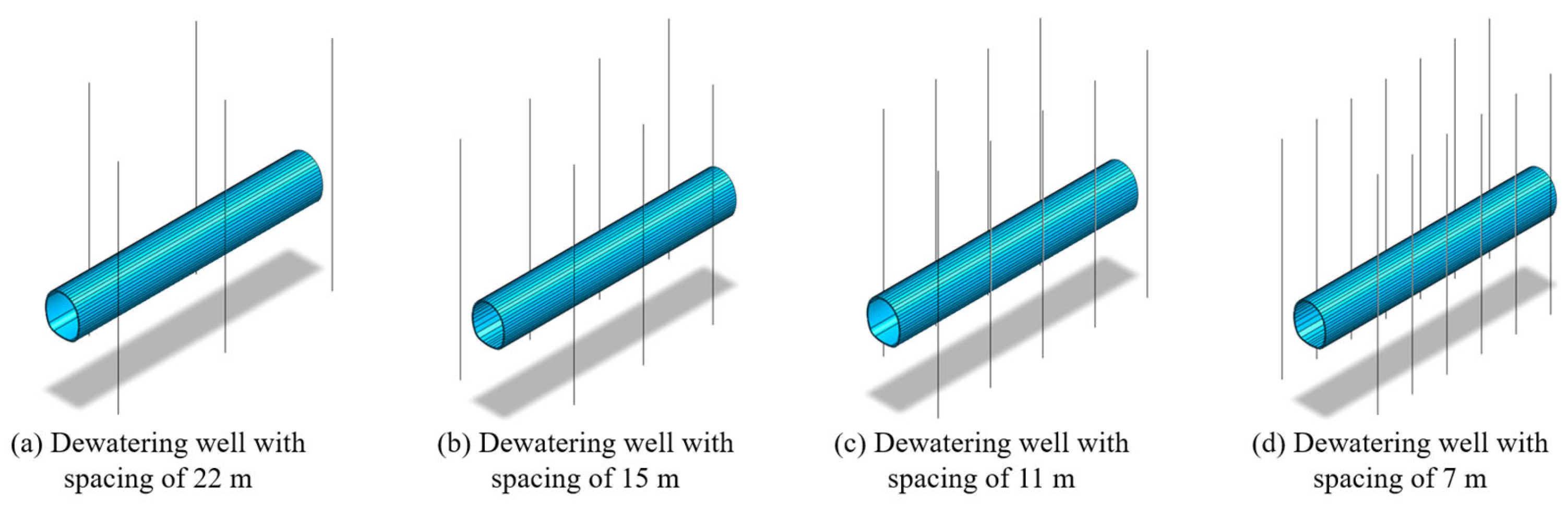
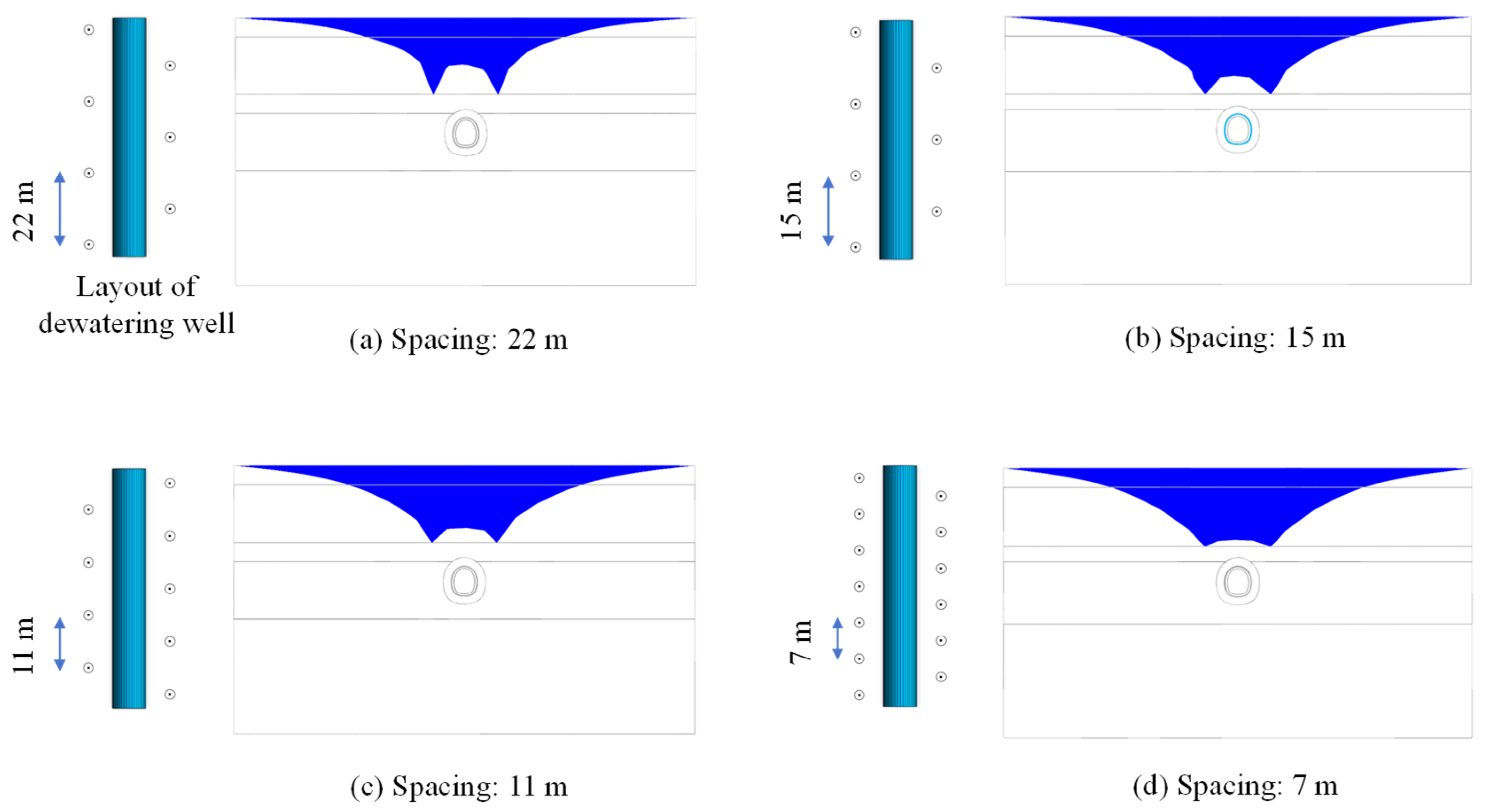
The numerical simulation focused on evaluating the influence of key design parameters for ground dewatering. Dewatering wells were arranged in a bilateral, staggered (quincunx) configuration (as shown in Figure 5) to optimize dewatering effectiveness. The wells were positioned longitudinally along the tunnel alignment, at a distance of 7.75 m from the tunnel axis. This arrangement ensures that the dewatering influence effectively covers the entire tunnel cross-section while avoiding direct interference with face excavation and support operations due to excessive proximity to the tunnel. Based on the tunnel invert design elevation, the bottom elevation of each dewatering well was set at 10 m below the tunnel invert. Four cases were selected with well spacings of 22 m, 15 m, 11 m, and 7 m, as shown in Figure 6. The 15 m spacing corresponds to the field arrangement. Additionally, the effects of dewatering depth and the horizontal distance between dewatering wells and the tunnel axis (e.g., 8 m, 15 m, and 30 m) were also investigated. In the various dewatering depth simulations, the groundwater level was lowered to the tunnel crown, 1 m below the invert, and 5 m below the invert by controlling the head boundary at the well bottom. The simulation cases are provided in Table 2. Dewatering stabilization was determined when the internal seepage field reached equilibrium (i.e., flow velocities stabilized).
Figure 6.
Layout of dewatering wells on both sides along the tunnel alignment.
Table 2.
Simulation cases summary.
3.3. Model Validation
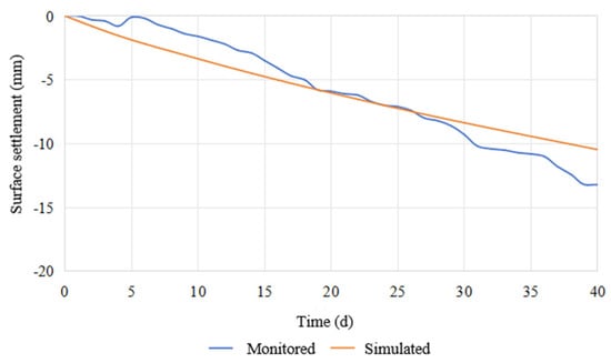
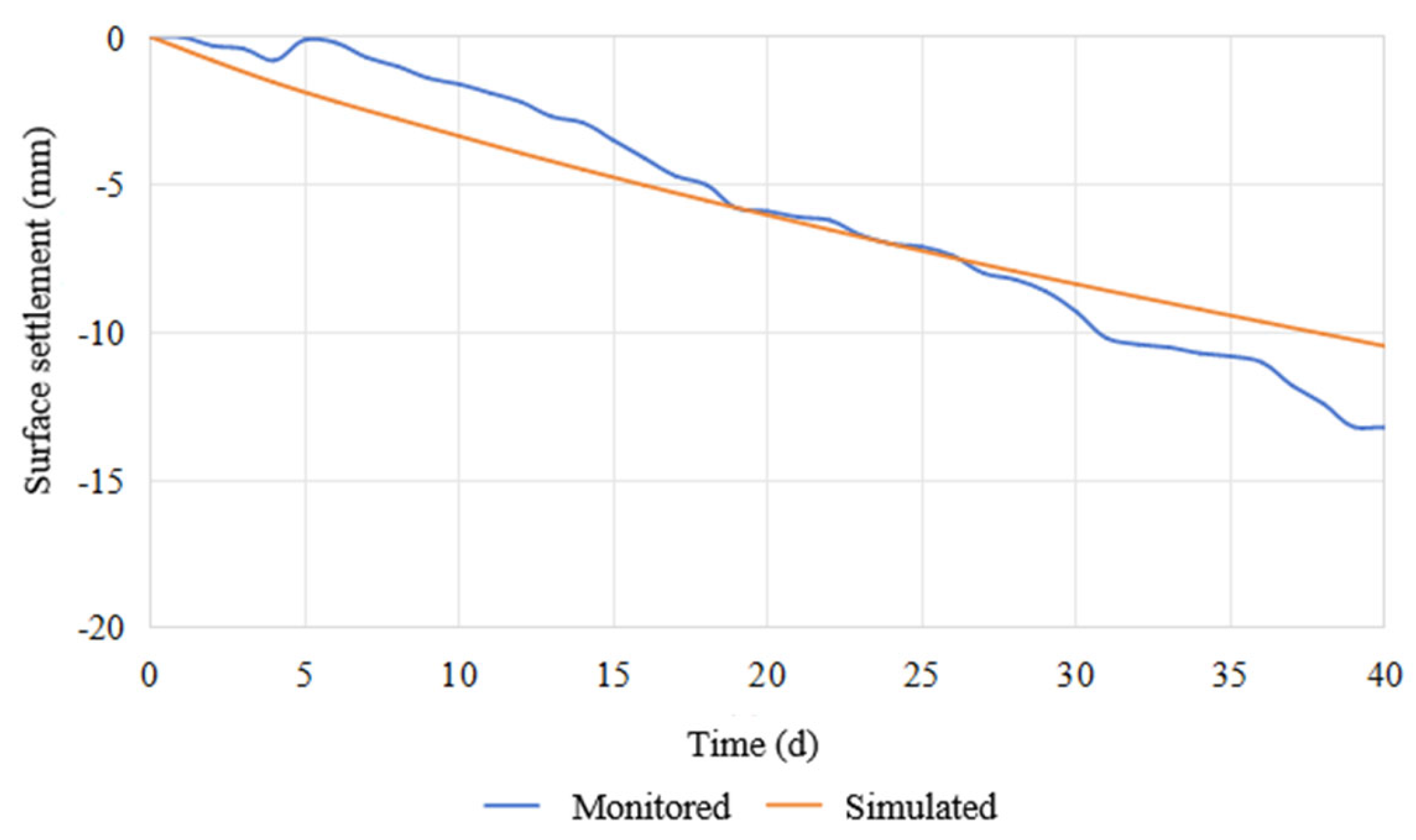
Since the strata contain different layers with different properties, it is difficult to adopt an available analytical solution for comparison with the simulation results. Herein, a comparison between monitored and simulated results is conducted. To ensure that the established numerical model could reasonably reflect the actual stratum response to dewatering in the engineering context, the computed surface settlement curve under the 15 m well spacing condition is compared with field monitoring data from the corresponding section. The results are presented in Figure 7. Continuous long-term field observation data of pore-water pressure and groundwater level were not available at this site for direct quantitative comparison, which constituted a limitation of the present validation. However, quantitative statistical indices, including root-mean-square error (RMSE), mean absolute error (MAE), and coefficient of determination (R2), are further adopted for evaluation. The calculated RMSE = 1.40 mm, MAE = 1.15 mm, and R2 = 0.90. The simulated maximum cumulative surface settlement is −10.5 mm occurring at day 40; the field monitored maximum settlement is −13.2 mm at day 39. It should be noted that mechanical and permeability parameters of materials were directly derived from site investigation reports; no parameter back-calibration or tuning against settlement monitoring data has been performed. The comparison shows that the surface settlement curve obtained from numerical simulation exhibits acceptable similarity in terms of the development trend to the field monitoring data, and the overall trends are consistent. This confirms that the three-dimensional fluid–solid coupled finite element model and its parameter selection are reasonable and reliable and can be used for subsequent quantitative comparative analysis and mechanistic studies of different dewatering schemes.
Figure 7.
Comparison between computed and monitored settlement due to surface dewatering.
4. Results
4.1. Water-Level Distribution and Stratum Settlement
Figure 8 presents the groundwater-level distribution across the tunnel section under four different well-spacing conditions in Cases A–D, with dewatering to 20 m below the ground surface. In Case A (well spacing 22 m), the drawdown funnel exhibits a relatively “steep” morphology, with an apparent water-level “depression” in the zone between adjacent wells, resulting in a distinctly undulating, wave-like water table across the entire section. This indicates that the dewatering influence is largely confined to the vicinity of the wells, while the inter-well zone suffers from poor dewatering effectiveness, yielding a discontinuous and non-uniform dewatering effect that may fail to provide a uniformly dry working environment for the entire tunnel cross-section. Compared with Case A, Case B (well spacing 15 m) produces a drawdown funnel with a relatively gentler morphology, and the inter-well water-level depression is markedly shallower. The undulation amplitude of the water table along the longitudinal tunnel axis is significantly reduced, the dewatering continuity is improved, and the dewatering performance is enhanced to a certain degree. Under the smaller well spacings of Cases C (11 m) and D (7 m), the drawdown funnel morphology further develops into a broad, gentle shape, forming a continuous, smoothly profiled “trough-shaped” dewatering depression. The water table along the tunnel axis is nearly horizontal, with only minor concavity immediately beneath the wells. This demonstrates that closely spaced wells can achieve continuous, uniform, and efficient dewatering along the tunnel alignment, facilitating the creation of overall stable excavation conditions.
Figure 8.
Water-level distribution with dewatering to 20 m below ground surface.
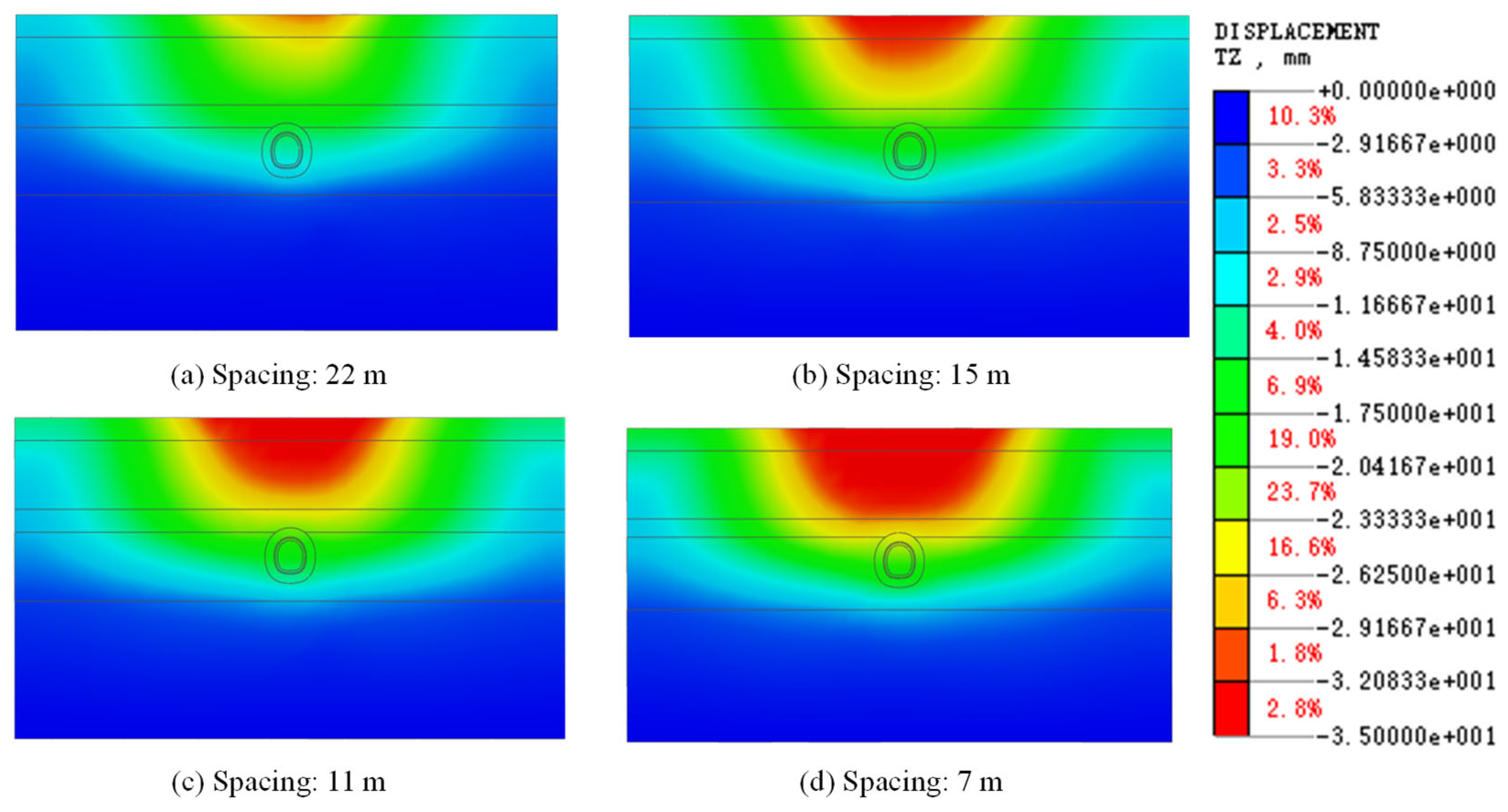
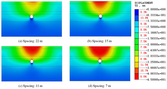
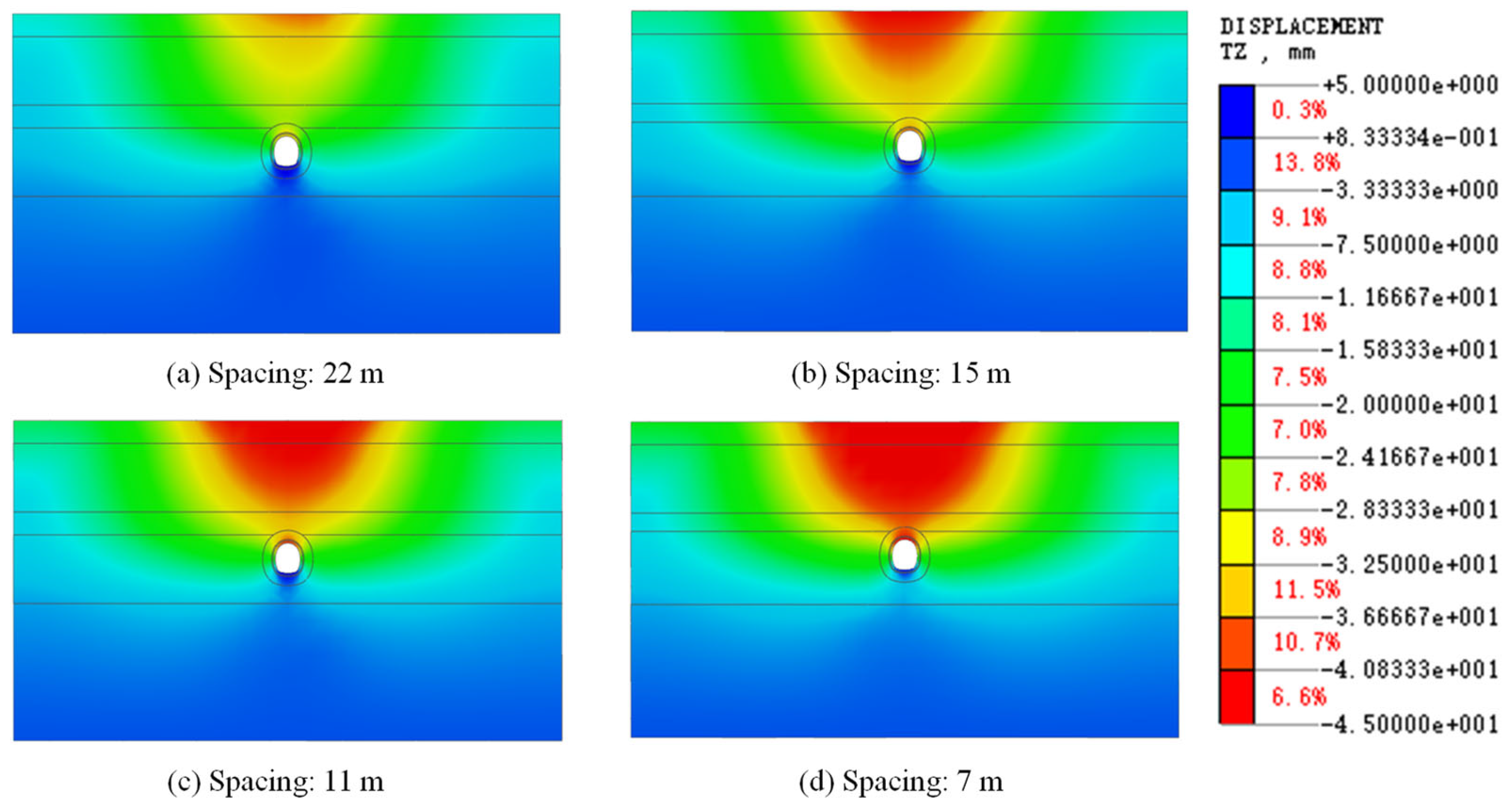
Figure 9 compares the strata settlement contours induced by dewatering in these four cases. To facilitate comparison, the maximum and minimum contour values were set identically across cases. It can be observed that as well spacing decreases, the total surface settlement induced by dewatering gradually increases, and the settlement distribution evolves from discrete point-like settlements around individual wells into a continuous, interconnected settlement trough. In Case A, the settlement magnitude is the smallest, and settlement is largely concentrated directly above each well, without forming a continuous settlement trough spanning the entire longitudinal extent of the model, exhibiting a “crest-shaped” discrete distribution. Cases B, C, and D all develop continuous “U-shaped” settlement troughs, with the trough width positively correlated with the influence range of the drawdown funnel. The trough widths in Cases C and D are notably larger than those in Cases A and B. Case D (spacing: 7 m) exhibits the largest total settlement and the greatest trough depth and width. This indicates that more densely spaced wells, while providing superior dewatering performance, also induce more significant settlement due to the dissipation of pore-water pressure over a larger area and to a greater extent.
Figure 9.
Settlement contours due to dewatering to 20 m below ground surface.
Figure 10 presents the strata settlement contours resulting from subsequent tunnel excavation after dewatering to 20 m below the ground surface under different well spacings (22 m, 15 m, 11 m, and 7 m). All cases exhibit a typical “settlement trough” distribution pattern, consistent with the fundamental behavior of ground displacement induced by tunnel excavation. As well spacing increases from 7 m (Case D) to 22 m (Case A), the maximum surface settlement induced by tunnel excavation actually exhibits a systematic increasing trend, and the influence zone of the settlement trough gradually widens. This phenomenon reveals the fundamental controlling role of dewatering effectiveness on excavation deformation: when well spacing is small (Cases C and D), dewatering is thorough and uniform, and the soil around the tunnel is effectively drained and reinforced, with the soil strength enhanced due to increased effective stress. Consequently, during subsequent excavation-induced unloading, the soil possesses greater inherent bearing capacity, resulting in smaller deformation. Conversely, when well spacing is large (Cases A and B), dewatering is insufficient and non-uniform, and the soil around the tunnel—particularly at the crown and haunch—may remain saturated or in a soft plastic state with low strength. During excavation, this weak soil is more prone to plastic flow and excessive deformation, leading to larger ultimate surface settlement. The dewatering- and excavation-induced maximum settlements in Cases A–D are presented in Table 3. It can be seen that the settlements in Cases B and C (well spacings of 11–15 m) fall in between in terms of the deformation magnitudes among the four cases.
Figure 10.
Stratum settlement contours due to tunnel excavation after dewatering to 20 m below ground surface.
Table 3.
Dewatering- and excavation-induced maximum settlements in Cases A–D.
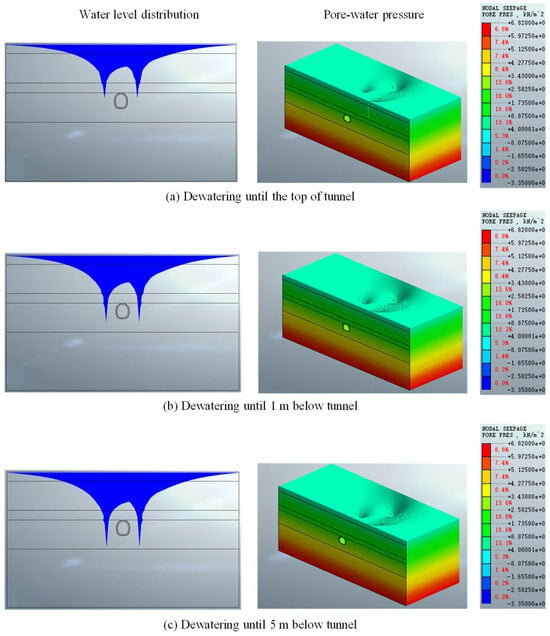
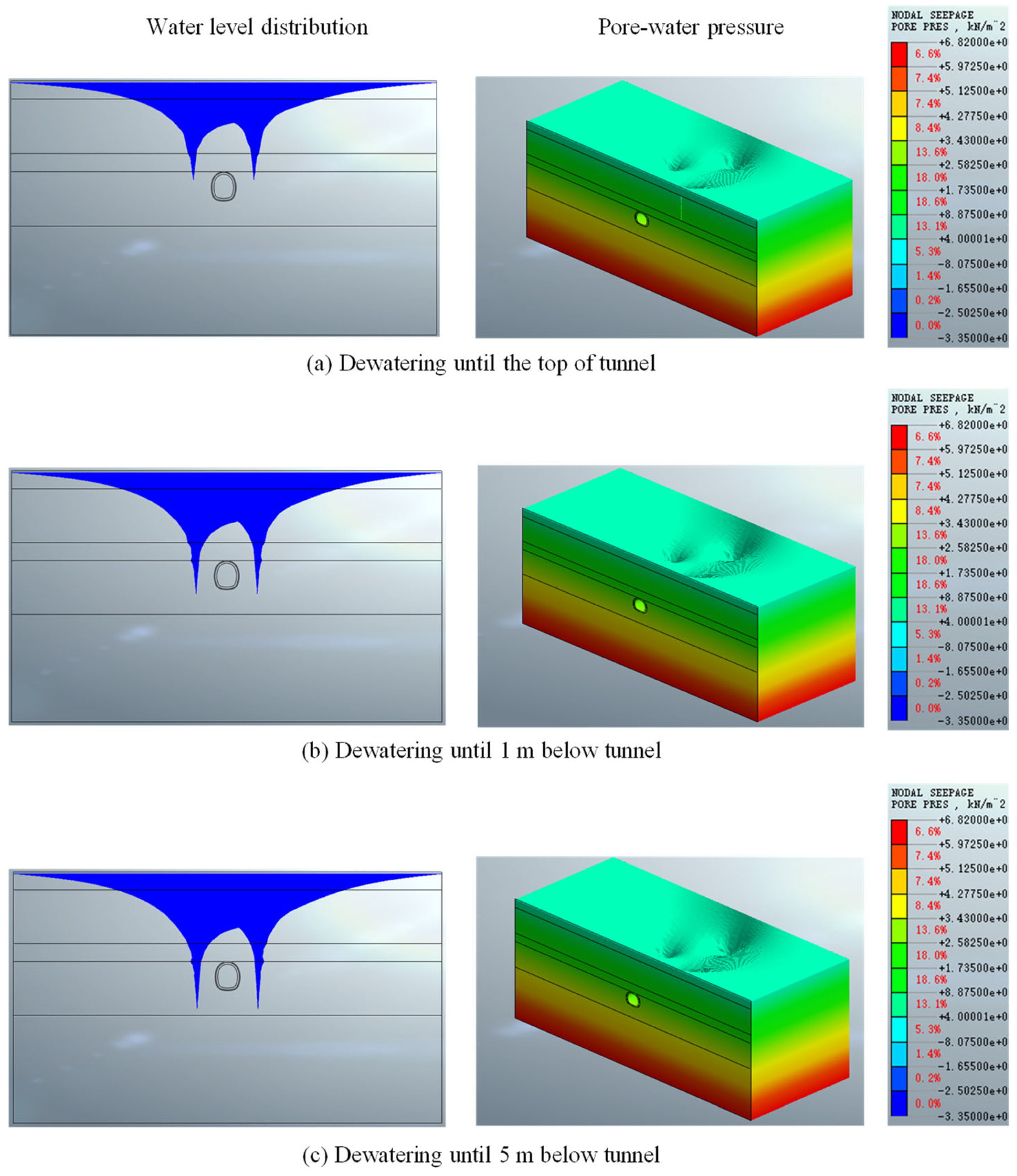
Figure 11 and Figure 12 further investigate the influence of dewatering depth in Cases E–G, demonstrating the groundwater-level and pore pressure distribution as well as deformation conditions when the water level is lowered to different elevations: the tunnel crown, 1 m below the invert, and 5 m below the invert. As dewatering depth increases, the groundwater table progressively declines. When dewatering reaches 1 m below the tunnel invert, a further reduction in the water level above the tunnel is observed compared with dewatering to the tunnel crown. However, when dewatering is extended to 5 m below the tunnel invert, the additional decline in the groundwater level becomes less pronounced, whereas the impact of dewatering on stratum settlement—particularly surface settlement—is substantial. The maximum equivalent strain in each case is approximately 0.006, 0.013, and 0.016. Analysis of surface settlement and soil shear strain contours under different dewatering depths reveals that as the dewatering depth increases from the tunnel crown to 5 m below the tunnel invert, both the width and maximum settlement value of the surface settlement trough increase significantly, while the extent and intensity of the shear strain concentration zone also markedly expand. This indicates that dewatering depth exerts a systematically amplifying effect on the ground deformation response. Specifically, when dewatering reaches the tunnel crown, settlement and shear strain are primarily concentrated in the immediate vicinity of the excavation contour, with limited influence extent. However, when the dewatering depth is further increased to 5 m below the tunnel invert, the larger drawdown funnel and more extensive groundwater unloading significantly modify the effective stress field, not only intensifying stress release and consolidation settlement near the excavation face, but also extending the plastic zone both deeper and laterally, with notably elevated shear strains in the soil. This reflects that while greater dewatering depth is beneficial for construction-stage stability, it also substantially enlarges the stratum disturbance zone and long-term deformation risks. Therefore, rational control of dewatering depth is essential in engineering practice to strike a suitable balance between excavation safety and suppression of excessive ground deformation.
Figure 11.
Groundwater-level and pore pressure distribution with dewatering to different targeted elevations below ground surface.
4.2. Stratum Settlement Trough
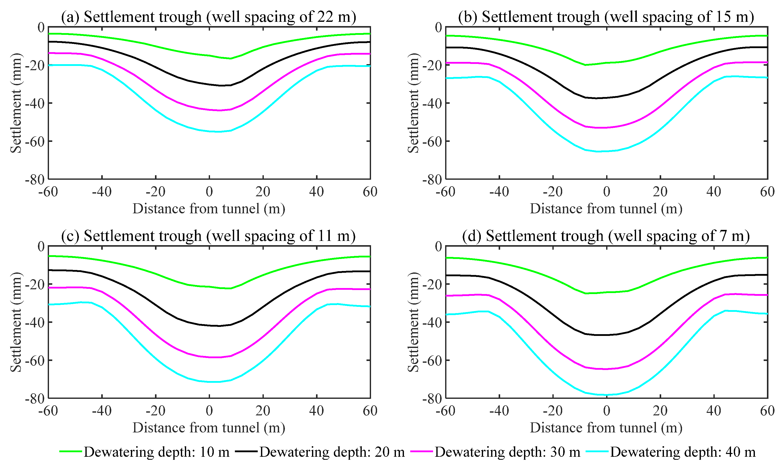
The surface settlement troughs induced by dewatering to different depths below the surface across the four cases are shown in Figure 13. All cases develop a settlement trough symmetrical about the tunnel centerline. All cases develop a settlement trough symmetrical about the tunnel centerline. Take the well spacing of 22 m as an example, when the dewatering depth is 10 m below the ground surface, the maximum settlement of the ground is only 16.7 mm, while when the dewatering depth continues to grow to 20 m, the maximum settlement rises to 30.9 mm, and as the dewater depth increases further to 30 m and 40 m, although the increment in each stage becomes slightly reduced, the total maximum settlement increases to 43.9 mm and 55.3 mm respectively. However, as well spacing decreases, the trough depth increases significantly. Case A exhibits a narrow and shallow “U” shape, while the trough in Case B transitions toward a deeper “U” shape. The troughs in Cases C and D display a typical “wide U-shaped” or “basin-shaped” pattern, with Case D exhibiting a slightly greater depth than Case C. Additionally, the settlement trough is essentially confined within approximately 40 m on each side of the tunnel. As dewatering depth increases, the trough deepens (i.e., the maximum surface settlement increases), while the trough extent does not continue to widen.
Figure 12.
Surface settlement and shear strain with dewatering to different positions below ground surface.
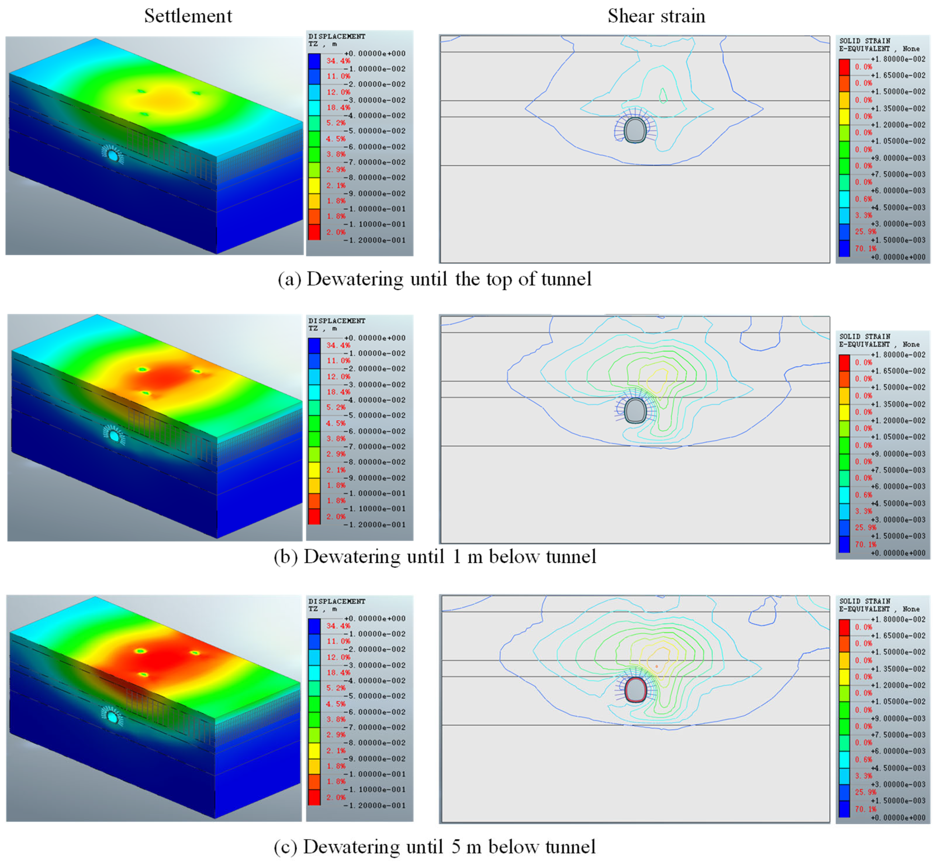
Figure 13.
Stratum settlement extent with dewatering to different positions below ground surface.
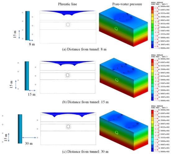
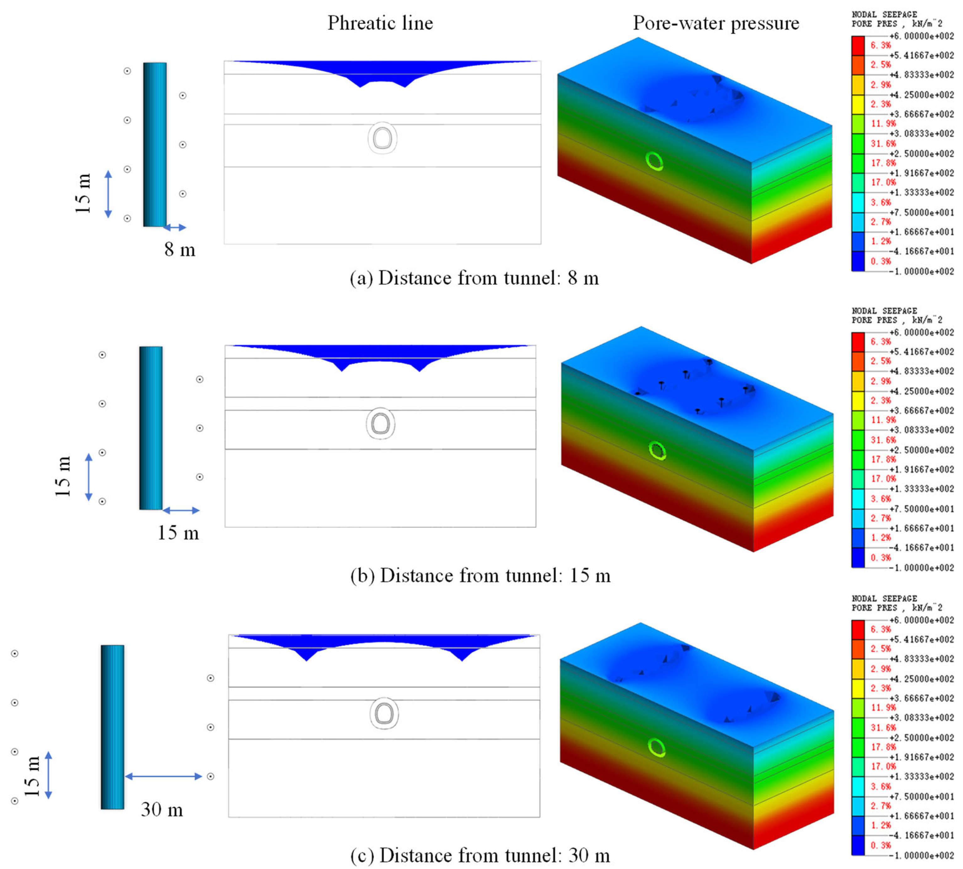
The water-level changes and pore-water pressure distributions that result when dewatering wells are located at varying distances from the tunnel axis in Cases H, I, and J are presented in Figure 14. When the wells are only 8 m away from the tunnel axis, the drawdown funnels from both sides strongly superimpose directly above the tunnel, forming a deep, large combined depression with substantial water-level drawdown in the tunnel-adjacent zone. When the well–tunnel distance increases to 15 m, the superimposition effect diminishes, and the water-level drawdown directly above the tunnel becomes limited. When the wells are positioned 30 m from the tunnel axis, no significant water-level decline is observed above the tunnel; drawdown funnels develop only in the immediate vicinity of the wells, with the two funnels remaining essentially independent, and the dewatering effect above the tunnel is minimal due to the excessive distance.
Figure 14.
Pore pressure distribution induced by dewatering under different well–tunnel distances.
The settlement induced by dewatering is shown in Figure 15. When the wells are 8 m from the tunnel axis, a single, narrow and shallow settlement trough forms above the tunnel, with its center slightly offset from the tunnel axis. The maximum settlement point is located on one side directly above the tunnel, with a concentrated influence zone. When the well–tunnel distance is 15 m, a wide and deep settlement basin forms above the tunnel, also slightly offset from the tunnel axis, with two settlement centers respectively located near each well, and the maximum settlement point occurs at the wells. When the well–tunnel distance is 30 m, no continuous settlement trough forms above the tunnel; instead, two completely separated small-scale double settlement basins develop, with centers near each well. This indicates that when wells are too distant from the tunnel, the dewatering effect is minimal, and the consolidation settlement induced by dewatering is also limited.
Figure 15.
Stratum settlement induced by dewatering under different well–tunnel distances.
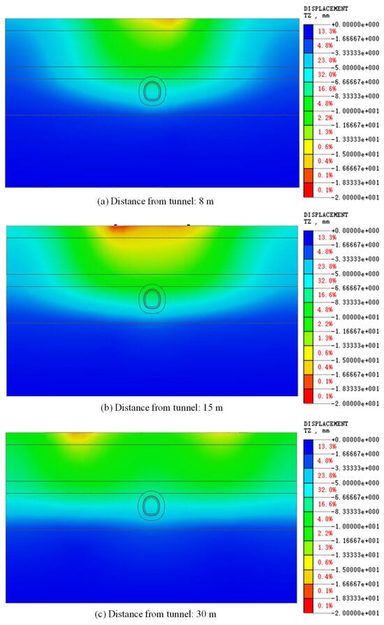
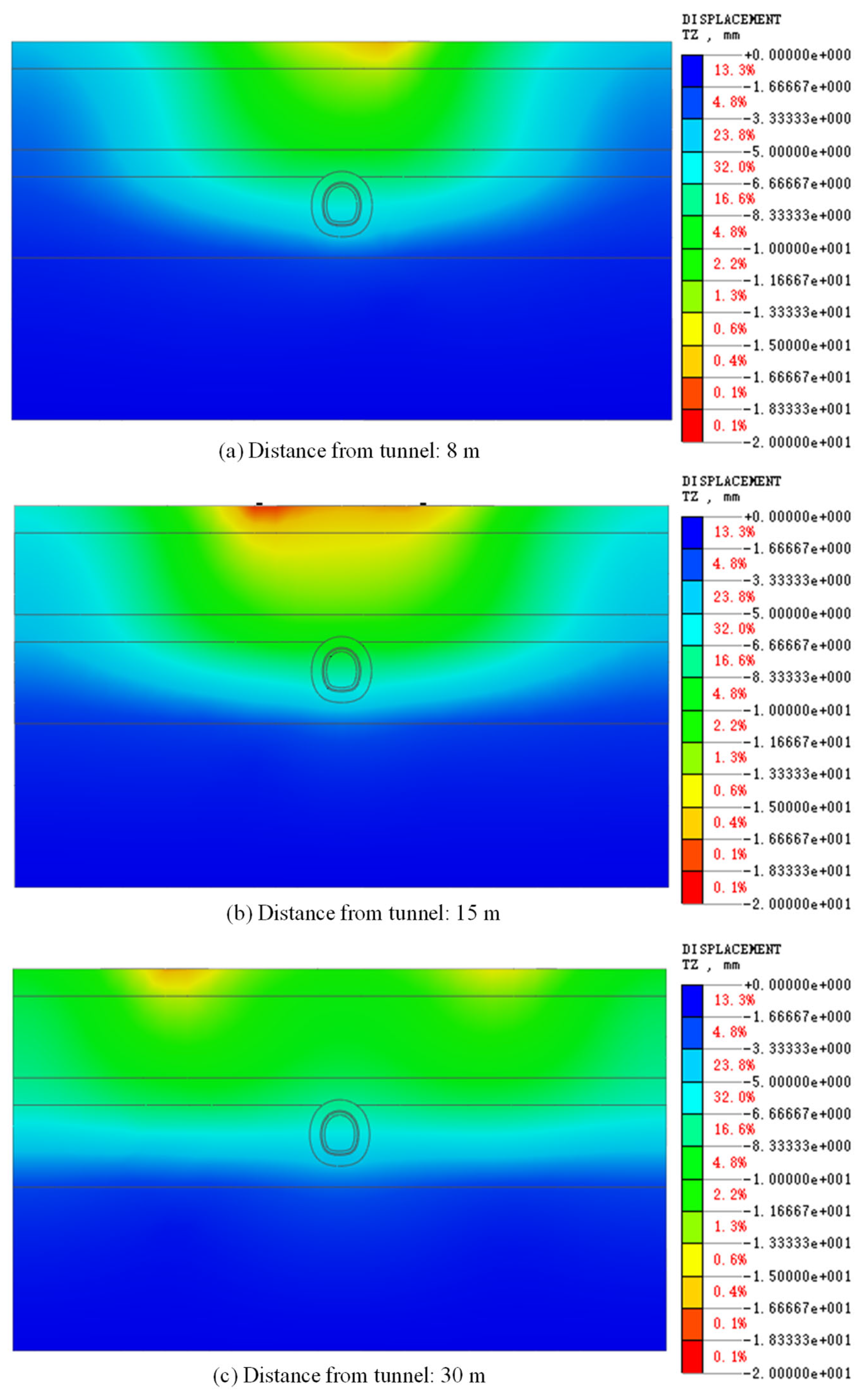
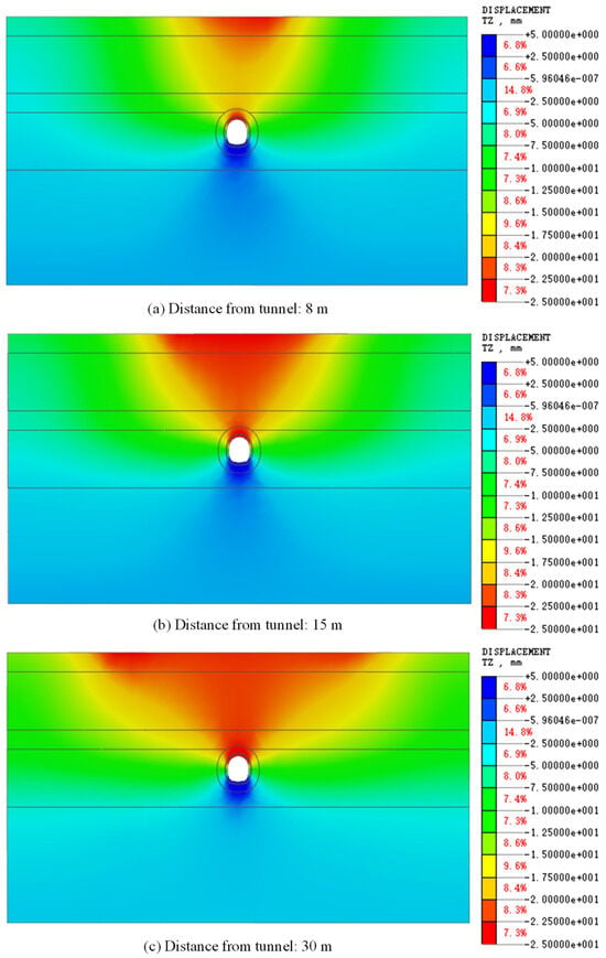
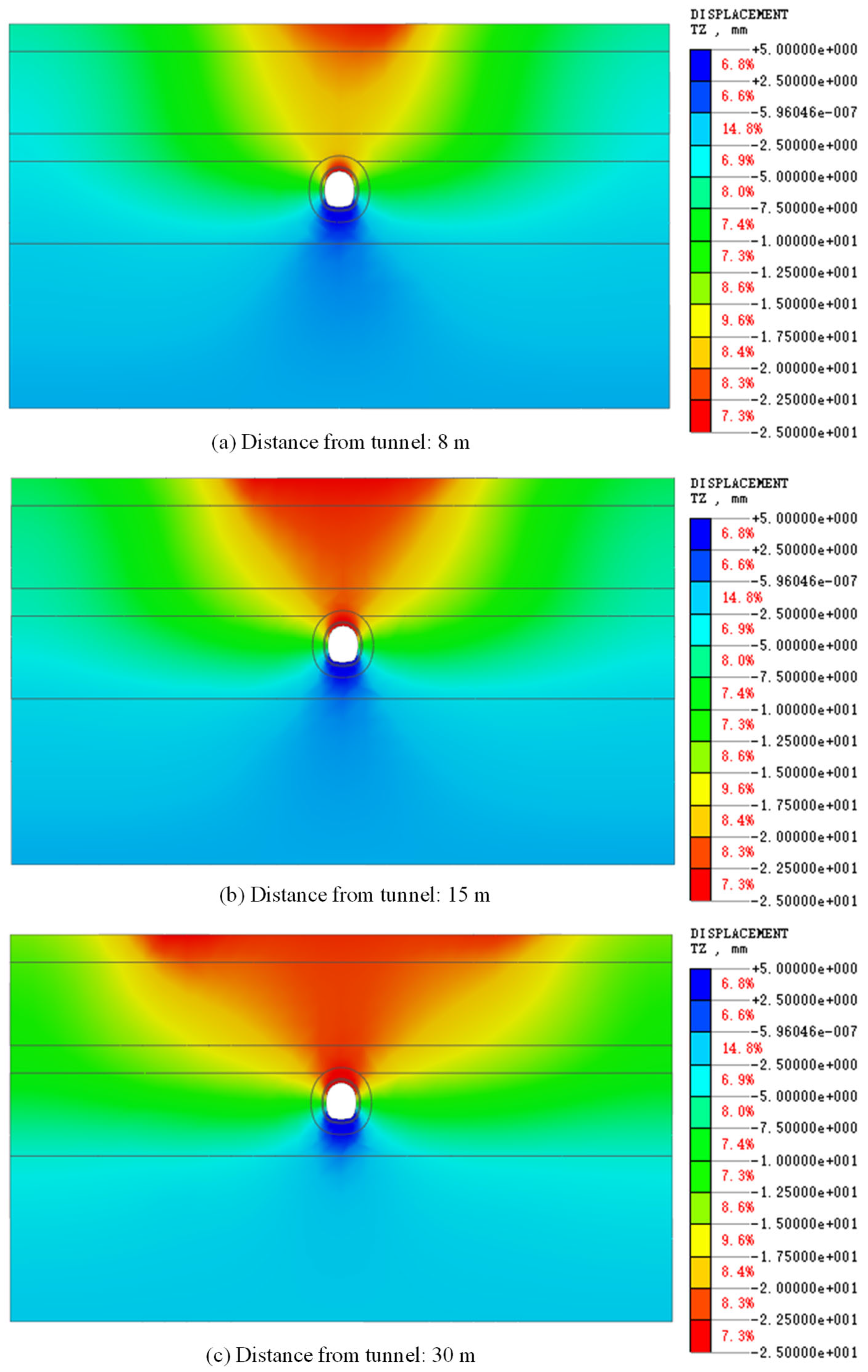
Following dewatering, tunnel excavation was simulated, and the excavation-induced ground settlement is shown in Figure 16. It is evident that as the well–tunnel distance increases, the dewatering effectiveness deteriorates, and the excavation-induced settlement becomes more pronounced. When the wells are located farther from the tunnel axis (e.g., 30 m), their dewatering efficiency in the tunnel-adjacent strata declines sharply, resulting in insufficient pore-water pressure dissipation and limited effective stress increase within the tunnel contour. Consequently, the support structure is subjected to larger and more uneven loads. Since the dewatering provides virtually no improvement to the tunnel zone, excavation proceeds entirely in weak, water-rich strata, rendering deformation difficult to control and ultimately leading to larger total surface settlement and a broader influence zone.
Figure 16.
Tunneling-induced ground settlement after dewatering under different well–tunnel distances.
From the above results, the following observations can be synthesized: with continued surface dewatering, the surface settlement trough progressively deepens, and settlement develops gradually at locations farther from the tunnel. The maximum settlement occurs directly above the tunnel axis, decreasing with increasing distance from the tunnel; beyond a certain distance, dewatering-induced settlement becomes negligible. At the same dewatering depth, decreasing well spacing leads to progressively larger ground settlement, with the smallest spacing yielding the most significant settlement. As well spacing decreases, the dewatering-induced settlement becomes increasingly evident, and the settlement trough extent gradually expands with increasing dewatering depth. At a fixed well spacing, greater dewatering depth induces more significant surface settlement. Reduced well spacing enlarges the dewatering zone within the stratum, particularly above the tunnel, where the groundwater-level decline is pronounced, thereby reducing excavation-induced deformation at the tunnel invert. As the distance between dewatering wells and the tunnel centerline increases, the water-level drawdown in the surrounding strata becomes less effective, resulting in increased tunnel deformation during excavation and compromising construction safety.
Furthermore, it can be observed that the essence of dewatering lies in the dual synergistic mechanisms of “pressure relief” and “consolidation.” Dewatering first reduces pore-water pressure, directly removing hydrostatic loads acting on the soil skeleton and support structure. Concurrently, pore-water expulsion triggers soil consolidation, with effective stress gradually increasing, leading to particle rearrangement and void ratio reduction. Pressure relief provides the driving force for consolidation, while the improved soil strength post-consolidation further optimizes the local seepage field. Ultimately, this synergistic effect operates from two fundamental directions—“load reduction” and “capacity enhancement”—systematically transforming the high-risk, saturated weak strata into low-risk, highly stable engineering foundations, thereby achieving effective control of excavation deformation.
5. Discussion
5.1. Interpretation of the Dewatering-Induced Consolidation Mechanism
The results presented in Section 4 demonstrate that surface dewatering exerts a dual influence on tunnel excavation behavior in water-rich completely weathered granite strata. On the one hand, dewatering improves the mechanical properties of the surrounding soil through effective stress enhancement; on the other hand, it induces additional consolidation settlement that may superimpose with excavation-induced deformation. This apparent paradox warrants a deeper discussion of the underlying coupled hydro-mechanical processes.
The increase in effective stress resulting from pore pressure dissipation is the primary mechanism by which dewatering enhances soil strength. The Terzaghi effective-stress principle is given as
where is the effective normal stress, is the total normal stress, and u is the pore-water pressure. According to the Mohr–Coulomb failure criterion, the shear strength of soil is governed by
where is shear strength, is effective cohesion, is the effective internal friction angle. As the groundwater table is lowered, the reduction in pore-water pressure (u) directly translates to an increase in effective stress (), thereby elevating the shear resistance of the stratum.
The increase in effective stress () resulting from pore pressure dissipation is the primary mechanism by which dewatering enhances soil strength. According to the Mohr–Coulomb failure criterion, the shear strength of soil is governed by . As the groundwater table is lowered, the reduction in pore-water pressure () directly translates to an increase in , thereby elevating the shear resistance of the stratum. This explains why Cases C (11 m spacing) and D (7 m spacing) exhibited notably smaller tunneling-induced settlement compared with Case A (22 m spacing), despite the former inducing greater dewatering-related consolidation settlement. The reinforcement effect was particularly pronounced within the tunnel-adjacent zone, where the drawdown funnel created a “dry shell” of improved mechanical properties surrounding the excavation contour.
5.2. Engineering Implications and Design Recommendations
Based on the parametric analysis and mechanistic interpretation presented above, the following practical recommendations are offered for the design of surface dewatering systems in similar water-rich completely weathered granite strata.
Two core criteria are adopted to balance dewatering effectiveness and ground settlement: (1) sufficient groundwater drawdown while maintaining insignificant settlement; (2) mitigation of excessive excavation-related ground settlement. Combined with the simulation results listed in Table 3, a well spacing of 22 m yields the lowest total settlement (43.77 mm) but creates prominent inter-well water-level depressions with discontinuous dewatering effects. The 11–15 m spacing produces continuous and uniform groundwater drawdown for tunnel excavation, while keeping total surface settlement at moderate magnitudes of 50.06 mm and 53.93 mm. Although the 7 m spacing achieves superior drawdown performance, it leads to larger total settlement (58.13 mm) and higher construction costs without proportionate benefits. Therefore, 11–15 m is proposed as the recommended well spacing range for comparable geological conditions. A spacing of 11–15 m is recommended as a reference for permeability coefficients on the order of 10−5 cm/s. This range provides sufficient drawdown overlap to ensure continuous and uniform dewatering along the tunnel alignment while limiting consolidation settlement to acceptable levels. As for the spacings considered in this study, spacings smaller than 10 m should be avoided unless exceptional circumstances require maximum dewatering effectiveness, as the marginal benefits do not justify the additional settlement and cost. Spacings larger than 20 m are unlikely to achieve satisfactory dewatering continuity and may leave the tunnel-adjacent zone inadequately depressurized.
A comprehensive monitoring system is essential to validate dewatering effectiveness and track consolidation settlement. Instruments should include piezometers to measure pore pressure response, surface settlement markers to monitor ground deformation, and inclinometers to detect lateral displacement. Real-time monitoring data should be used to adjust pumping rates and well operation schedules dynamically, allowing adaptive management of the dewatering process.
5.3. Limitations and Future Research Directions
While this study provides valuable insights into the effects of surface dewatering on tunnel deformation in water-rich completely weathered granite, several limitations should be acknowledged:
- (1)
- Homogeneous stratigraphic assumption: The numerical model assumed homogeneous, isotropic permeability and mechanical properties within each stratigraphic layer. Completely weathered granite strata exhibit significant heterogeneity at multiple scales, with localized zones of higher permeability associated with fractures and weathering fronts. The Mohr–Coulomb model used in this study cannot reproduce softening mechanisms due to saturation, which imposes important constraints on interpreting model outputs. For real-world linear tunnel projects crossing variable geological zones, spatial heterogeneity of material parameters should be carefully considered before directly applying the present research outcomes. Future studies should consider stochastic representation of permeability heterogeneity and its effects on dewatering performance.
- (2)
- Neglect of time-dependent behavior: The Mohr–Coulomb model employed in this study captures the elastoplastic response but does not account for the time-dependent deformation characteristics (creep and stress relaxation) that are particularly relevant for soft rock and residual soil strata. Incorporating visco-plastic constitutive models would enable more accurate prediction of long-term deformation after dewatering and excavation.
- (3)
- Single-tunnel configuration: This study focused on a single tunnel section with a specific cross-section geometry and burial depth. The generalizability of the findings to double-tube tunnels, larger cross-section excavations, or significantly different burial depths should be investigated in future work.
- (4)
- Environmental considerations: This study did not explicitly consider the environmental consequences of groundwater lowering, including impacts on adjacent groundwater-dependent ecosystems, water supply wells, and existing building foundations. Particularly for urban tunnel projects, these environmental side effects induced by groundwater drawdown must be fully evaluated within comprehensive risk assessment frameworks before adopting the proposed practical dewatering range in engineering practice. These externalities should be incorporated into a comprehensive risk assessment framework when designing dewatering schemes for urban tunnel projects.
6. Conclusions
Based on the water conveyance tunnel project in Shenzhen traversing a water-rich completely weathered granite stratum, this study investigated the influence mechanisms of key dewatering parameters—well spacing, dewatering depth, and well–tunnel distance—on the groundwater-level field, stress field, and displacement field. The reinforcement effectiveness of different dewatering schemes in suppressing tunnel excavation deformation was quantitatively evaluated. The main conclusions are as follows:
- (1)
- Well spacing significantly influences dewatering effectiveness and stratum settlement. Excessive well spacing (e.g., 22 m) results in a “wave-like” undulating drawdown funnel, discontinuous dewatering in the tunnel axis zone, and an overall non-uniform dewatering effect. As well spacing decreases (15 m, 11 m, and 7 m), the drawdown funnel morphology progressively flattens, the water-level drawdown becomes continuous and uniform, and dewatering performance is markedly improved. Concurrently, reduced well spacing leads to an increase in the total surface settlement induced by dewatering, with the settlement trough evolving from discrete “crest-shaped” patterns to a continuous “U-shaped” or “basin-shaped” profile, accompanied by an expanded settlement influence zone.
- (2)
- Dewatering depth is a critical factor governing stratum deformation and excavation stability. Progressively increasing the dewatering depth from the tunnel crown to 5 m below the tunnel invert, while effectively lowering the groundwater table and enhancing effective stress, also significantly enlarges the extent of consolidation settlement and shear strain induced by dewatering. Greater dewatering depths produce appreciable increases in both the width and maximum settlement value of the excavation-induced surface settlement trough, with the plastic zone extending both deeper and laterally. This reflects a positive correlation between dewatering depth and the extent of stratum disturbance and long-term deformation risk.
- (3)
- The distance between dewatering wells and the tunnel axis directly influences the control effectiveness of dewatering on excavation deformation. When wells are relatively close to the tunnel axis (e.g., 8 m), the drawdown funnels strongly superimpose above the tunnel, effectively dewatering the surrounding soils and significantly reducing excavation-induced ground settlement. As the well–tunnel distance increases (15 m, 30 m), the dewatering effectiveness gradually diminishes, the water-level drawdown in the tunnel zone becomes limited, and the consolidation settlement induced by dewatering decreases. However, the total surface settlement induced by excavation conversely increases, accompanied by an expanded settlement influence zone.
- (4)
- The numerical results further quantify and validate the dual mechanism of surface dewatering as an active deformation control measure in tunnel construction through water-rich weak strata. On the one hand, it reduces pore-water pressure, thereby decreasing the hydrostatic load acting on the support structure. On the other hand, it enhances effective stress through soil consolidation, improving soil strength and the deformation modulus.
- (5)
- In engineering practice, dewatering designs should be improved by comprehensively considering dewatering effectiveness and settlement control. Based on the simulated cases analyzed in this study, for water-rich completely weathered granite strata, adopting a moderate well spacing (e.g., 11–15 m) and controlling the dewatering depth to approximately the tunnel invert level can effectively dewater the stratum while minimizing additional settlement for tunnels under investigation in this study. It should be noted that this practical range is derived under the specific stratigraphic, permeability, single-tunnel geometry conditions of the present case study; direct application for other geological or tunnel configurations requires further validation.
Author Contributions
Conceptualization, J.X. (Jianghe Xin) and S.Y.; methodology, J.X. (Jiawei Xu) and Y.L.; data curation, formal analysis, validation, and writing—original draft preparation, J.X. (Jiawei Xu); writing—review and editing, S.Y.; project administration, X.C.; funding acquisition, B.Z. All authors have read and agreed to the published version of the manuscript.
Funding
This research was funded by the Science and Technology Innovation Fund Project of CCCC First Highway Consultants Co., Ltd., grant number KCJJ2024-22.
Data Availability Statement
The data presented in this study are available upon request from the corresponding author.
Conflicts of Interest
Author Bo Zhang, Shaozhan Yang, Jianghe Xin, Xiaoyong Cao, and Yukun Li were employed by the company CCCC First Highway Consultants Co., Ltd. The remaining authors declare that the research was conducted in the absence of any commercial or financial relationships that could be construed as a potential conflict of interest.
References
- Papadomarkakis, D.; Paraskevopoulou, C. Valuation methodologies and practical guidelines for urban underground space—A review. Tunn. Undergr. Space Technol. 2027, 179, 108049. [Google Scholar] [CrossRef] [Scilit]
- Zhao, Y.; He, H.; Wu, K.; Shi, X. Multi-dimensional evaluation and regulation of underground space in densely built-up areas: A case study of Beijing, China. Tunn. Undergr. Space Technol. 2026, 178, 108036. [Google Scholar] [CrossRef] [Scilit]
- Bertrand, L.; Roze, C. Sensitive integration of underground spaces in Helsinki’s urban fabric: From geology to architecture. Tunn. Undergr. Space Technol. 2026, 176, 107873. [Google Scholar] [CrossRef] [Scilit]
- Huang, M.; Zhang, Z.; Tan, Z. Construction model of deep tunnel for urban flood control and drainage in China. China Civ. Eng. J. 2017, 50, 76–81. [Google Scholar]
- Ou, Q.; Yang, C.; Liu, M. Deformation analysis of rock mass during the excavation of a new tunnel. Appl. Sci. 2026, 16, 10075. [Google Scholar] [CrossRef] [Scilit]
- Li, L.; Lei, T.; Wang, M.; Liu, W.; Lu, W.; Liu, G. Mechanical behavior and stability analysis of underground excavation construction: Case study of large-span and variable cross-section subway crossover tunnel. Appl. Sci. 2026, 16, 9230. [Google Scholar] [CrossRef] [Scilit]
- Lu, J.; Li, Y.; Jia, N.; Wei, P.; Li, C.; Yu, Y.; Yao, A. Ground-surface settlement control and prediction for twin tunnels excavated above an existing tunnel: Effects of existing-tunnel constraint. Appl. Sci. 2026, 16, 9345. [Google Scholar] [CrossRef] [Scilit]
- Sun, P.; You, K.; Zhao, J.; Zhu, C.; Shi, D. Resilience evaluation of urban tunnel operations based on multi-source data and explainable artificial intelligence. Appl. Sci. 2026, 16, 9782. [Google Scholar] [CrossRef] [Scilit]
- Zhang, Y.; He, K.; Hu, X.; Liu, W.; Sui, S.; Luo, G.; Han, M. Integrated geophysical and computational modeling of hydromechanical mechanisms of underground debris flows in mining region. Undergr. Space 2025, 25, 33–53. [Google Scholar] [CrossRef] [Scilit]
- Gong, C.; Yang, Z.; Cheng, M.; Zhu, H.; Yan, Z. Leakage mechanism of double-gasketed segmental joint in shield tunnel under interacting internal and external water pressures. Tunn. Undergr. Space Technol. 2026, 174, 107673. [Google Scholar] [CrossRef] [Scilit]
- Xie, X.-C.; Zhang, D.-M.; Zhou, M.-L. Evolution of mechanical properties of shield tunnels induced by water-soil gushing. Undergr. Space 2026, 26, 82–105. [Google Scholar] [CrossRef] [Scilit]
- Song, W.; Cheng, S.; Zi, J.; Jin, H.; Jiang, X.; Wang, J. Intelligent detection method for tunnel water inrush disasters based on deep learning. Tunn. Undergr. Space Technol. 2026, 172, 107549. [Google Scholar] [CrossRef] [Scilit]
- Wang, Q.; Liu, X. Analysis of the relationship of water ratio to the stability of surrounding rock in a tertiary water-rich fine sandstone stratum. Mod. Tunn. Technol. 2012, 49, 1–5, 16. (In Chinese) [Google Scholar]
- Wang, G.; Luo, L. Study of tunnel dewatering technology in water-rich immature fine silty sand strata. Tunn. Constr. 2018, 38, 142–147. (In Chinese) [Google Scholar]
- Huo, R.; Tian, Q.; Li, S.; Cao, X.; Qian, M. Strata deformation law of water-rich loess tunnel in different reinforcement schemes. J. Chang. Riv. Sci. Res. Inst. 2020, 37, 96–104. (In Chinese) [Google Scholar]
- Wang, Z.; Jiang, Y.; Xian, Y.; Qi, Y.; Li, J.; Zhang, H.; Zhou, P. Causes and countermeasures of tunnel catastrophe in water-rich sandy dolomite stratum. J. Railw. Eng. Soc. 2025, 42, 56–61. (In Chinese) [Google Scholar]
- Wang, J.; Zhang, Q.; Lei, M.; Xu, J.; Lei, H.; Cao, A.; Long, Y. Field experiment and numerical simulation on sequence dewatering of a sand inrush tunnel under high water pressure in semi-diagenetic rock: A case study. Environ. Earth Sci. 2025, 84, 287. [Google Scholar] [CrossRef] [Scilit]
- Meng, F.; Chen, R.; Wu, H.; Xie, S.; Liu, Y. Observed behaviors of a long and deep excavation and collinear underlying tunnels in Shenzhen granite residual soil. Tunn. Undergr. Space Technol. 2020, 103, 103504. [Google Scholar] [CrossRef] [Scilit]
- Jia, R.; Shan, Y.; Yang, K.; Wang, Y.; Hu, Z.; Li, Y.; Cui, J. Effect of suffusion on deterioration of weathered granite soil: A multi-scale study from macroscopic to microscopic investigations. Acta Geotech. 2025, 20, 4213–4229. [Google Scholar] [CrossRef] [Scilit]
- Jaffar, S.T.A.; Khan, H.; Jalal, F.E.; Bao, X.; Chen, X. A novel study on polyhydroxyalkanoate biopolymer as an eco-friendly binder for granite residual soil. Acta Geotech. 2026, 21, 3049–3063. [Google Scholar] [CrossRef] [Scilit]
- Jalal, F.E.; Khan, H.; Jaffar, S.T.A.; Al-Osta, M.A.; Chang, I. Multiscale evaluation of bio-treated residual granitic soil strength for sustainable applications. Eng. Geol. 2026, 367, 108741. [Google Scholar] [CrossRef] [Scilit]
- Liu, X.; Zhang, X.; Kong, L.; Wang, G.; Lu, J. Disintegration of granite residual soils with varying degrees of weathering. Eng. Geol. 2022, 305, 106723. [Google Scholar] [CrossRef] [Scilit]
- Liu, X.; Zhang, X.; Kong, L.; Wang, G.; Liu, H. Formation mechanism of collapsing gully in southern China and the relationship with granite residual soil: A geotechnical perspective. Catena 2022, 210, 105890. [Google Scholar] [CrossRef] [Scilit]

Disclaimer/Publisher’s Note: The statements, opinions and data contained in all publications are solely those of the individual author(s) and contributor(s) and not of MDPI and/or the editor(s). MDPI and/or the editor(s) disclaim responsibility for any injury to people or property resulting from any ideas, methods, instructions or products referred to in the content. |
© 2026 by the authors. Licensee MDPI, Basel, Switzerland. This article is an open access article distributed under the terms and conditions of the Creative Commons Attribution (CC BY) license.