


Abstract
Distributed electric propulsion has renewed interest in whirl flutter, since multiple propellers on highly flexible wings introduce aeroelastic characteristics that differ from those of the turboprop aircraft for which the classical theory was developed. With the total propeller disk area held constant, the individual propellers are resized and repositioned along the wing span to examine how their distribution influences the whirl flutter stability boundary. A four-propeller wing is modeled using a Galerkin discretization of the flexible wing, coupled with rigid propeller units mounted on flexible pylons. The propeller aerodynamic loads are determined using the Houbolt–Reed theory, with corrections accounting for compressibility and finite blade aspect ratio, and the coupled system is analyzed using both a frequency-domain and an augmented time-domain formulation. Three propeller layouts with the same total disk area and propeller mass are examined in detail, and the continuous range of configurations between them is then swept at each spanwise location. The results indicate that concentrating the total disk area into a single larger propeller has the most significant effect on the whirl flutter stability margin, while the underlying backward-whirl instability mechanism remains unchanged. A moderate concentration of the disk area toward the inboard region of the wing provides a small improvement of 3.6%. Spanwise placement has a secondary influence and becomes less significant as the disk area becomes increasingly concentrated.
1. Introduction
Environmental targets for civil aviation have become demanding enough to force a change of propulsion architecture. Flightpath 2050 calls for a 75% reduction in CO2, 90% in NOx, and 65% in noise relative to year-2000 levels [1], and Destination 2050 commits European commercial aviation to net zero [2]. Distributed electric propulsion (DEP), in which multiple small propellers are distributed along the wing span, offers a promising approach to these challenges. The blown wing can increase lift, while the spanwise distribution of propellers provides direct control over the lift distribution. In addition, the use of smaller propellers can reduce tip speeds and, consequently, propeller noise. However, this architecture carries a structural penalty. Because battery energy density remains low, DEP designs compensate with slender, lightweight, high-aspect-ratio wings so that a set of rotating masses is distributed along a structure considerably more flexible than the one a conventional turboprop is mounted on.
The aeroelastic consequence of this arrangement is whirl flutter, a self-excited precession of a propeller on a flexible mount in which gyroscopic moments couple pitch to yaw and the unsteady disk loads feed the motion so that, unlike bending–torsion flutter, it is intrinsically three-dimensional [3,4]. Taylor and Browne [5] first showed that this coupling splits the mount frequencies into forward and backward precession and that the backward branch can go unstable, a result made quantitative by Ribner [6] and Reed and Bland [7] and confirmed in the wind tunnel, where inboard nacelles proved the more vulnerable [8]. Houbolt and Reed [9] cast the disk aerodynamics as quasi-steady derivatives built from radial integrals of the blade loading, still the basis of most engineering-level analysis. For an elastic wing, the behavior changes considerably, with the wing generally contributing a stabilizing effect similar to that of a tuned absorber. At the same time, the gyroscopic terms strongly couple the nacelle and wing motions, as experimental and analytical studies have shown [10,11,12,13].
Research on DEP wings specifically is more recent. Massey et al. [14] identified static divergence as the critical instability of early X-57 configurations analyzed without active propellers, while Hoover et al. [15] showed that flexibility in the motor-mount faceplate alone was sufficient to bring whirl flutter inside the operational envelope. Bohnisch et al. [16] found distinct stability dips along the span of a DEP wing and observed that wing-dominant modes, other than the whirl modes themselves, may govern the boundary. The same group subsequently established the conditions separating the two mechanisms: for a slender wing–propeller system, soft mounts produce whirl flutter and stiff mounts produce wing flutter, and the spanwise station of the unit alters the wing mode shapes and with them the flutter mechanism itself [17]. Aerodynamic interference between disk and wing was later shown to lower the boundary by a further 5% or so, thrusting conditions being more destabilizing than windmilling [18]. A further refinement of similar significance is to account for blade flexibility. Koch and Koert [19] incorporated elastic blade deformation into a frequency-domain whirl flutter analysis and showed that it has a stabilizing effect by reducing the aerodynamic cross-coupling moment. Closest in spirit to the present study, Bohnisch et al. [20] varied the number of propellers from one to five at constant disk loading and total mass, reporting wing flutter as the governing mechanism throughout, a single tip-mounted unit as the most stable arrangement, and an overall loss of margin as the count increased, although clustering the units near the tip could partly offset it. Wang et al. [21] reached a compatible conclusion from an optimization study, finding that flexible pylons degrade the margin substantially and that wingtip-mounted propellers are the most damaging placement; the same group later embedded a whirl flutter constraint directly within a laminate-tailoring optimization [22] so that the instability sizes the structure rather than being verified once the structure is fixed.
Taken together, these studies vary the number of propellers, their spanwise station, or the stiffness of their mounts, the units within any one layout being identical. A related question is what happens when the count and the installed disk area are both held fixed and the units are instead allowed to differ in size so that only the distribution of that area among them is altered, since this is the quantity a DEP designer trades against propulsive requirements once the total has been set. The configuration considered here also falls within the soft-mount regime identified in [17], where whirl flutter, rather than wing flutter, is expected to determine the stability boundary. This provides a useful basis for comparison with the stiffer configurations examined previously.
The objective of this study is to investigate how redistributing a fixed total propeller disk area among a fixed number of units affects the whirl flutter stability boundary of a flexible wing while isolating the effects of relative propeller size and spanwise location. Unlike previous studies that vary propeller count, spanwise position, or mount stiffness, the present work focuses on disk-area distribution as an independent design variable once the total installed area has been established by propulsive and acoustic requirements. Within this context, the present study examines whirl flutter for a flexible wing carrying four propellers. The structure is modeled using a Galerkin discretization of the flexible wing, coupled with rigid propeller units mounted on flexible pylons. The propeller aerodynamic loads and moments are determined using the Houbolt–Reed theory, with corrections accounting for compressibility and aspect ratio. The isolated propeller on a flexible mount is analyzed first with the same derivative set, which isolates the effect of these corrections on the whirl flutter boundary and allows the aerodynamic model to be checked against published measurements before the wing is introduced. The coupled aeroelastic system is then analyzed using both a frequency-domain approach and an augmented time-domain approach. The two methods show close agreement in the predicted flutter speed and frequency for all oscillatory stability boundaries. Modal branches are tracked with airspeed using the Modal Assurance Criterion (MAC) and are further identified through two complementary participation measures. Agreement between two independent solutions of the same model is used as an internal check throughout. Branches are tracked across airspeed by the modal assurance criterion and identified by two complementary participation measures, which together distinguish a whirl instability from a wing mode that has absorbed the propeller motion. Several propeller layouts are examined, along with the continuous range of configurations between them. The results show that propeller size distribution has a stronger influence on stability than spanwise placement. Concentrating the disk area into a single larger propeller reduces the stability margin, whereas moderate inboard concentration provides a small improvement.
2. Aeroelastic Model
This section describes the formulation and assembly of the structural and aerodynamic components into a unified aeroelastic model. The physical formulation of each component is presented, including the wing discretization, the Houbolt–Reed propeller aerodynamics, the unsteady wing aerodynamics, and the resulting coupled system. The model couples a Galerkin discretization of the flexible wing with a set of rigid propeller–nacelle units mounted on flexible pylons. The resulting system can accommodate an arbitrary number of propellers. The assembled system matrices are presented block by block in Appendix A.
2.1. Structural Model
The wing is modeled as a non-uniform cantilevered elastic beam. The continuous equations of motion for flapwise bending and torsional rotation are discretized by Galerkin’s method with admissible shape functions
where and satisfy the boundary conditions of a beam clamped at the root and free at the tip, and , are the generalized coordinates. Projecting the beam equations onto these functions gives the wing mass and stiffness matrices, written out in Appendix A.4.
Each of the propeller units adds two angular degrees of freedom relative to the wing elastic axis: a pylon pitch and a pylon yaw . The generalized coordinate vector therefore contains entries, ordered with the pylon rotations first and the wing coordinates last as in Appendix A. In the frequency-domain solution, this gives states. The time-domain solution adds two aerodynamic lag states for each wing coordinate, that is, further states, giving in total.
2.2. Propeller Aerodynamics
Each propeller–nacelle unit generates unsteady forces and moments through its pitch and yaw deflections, their rates, and the motion of the hub carried by the wing. Following Houbolt–Reed strip theory [9], the sectional contributions are integrated across the disk.
2.2.1. Compressibility, Finite Span, and Lag Corrections
Compressibility and the finite blade aspect ratio following [23,24] are accounted for by correcting the sectional lift slope with the Prandtl–Glauert factor and a three-dimensional induction term,
with M the axial Mach number, the normalized radius, the advance ratio, and the hub radius.
Here is the square of the local resultant Mach number at the section. Equation (2) is the product of the Prandtl–Glauert slope , with , and the finite-span factor evaluated in the transformed plane, where . The compressible slope is limited to , which restricts to .
As the disk precesses, a trailing helical vortex wake is shed behind it. The resulting circulation lag is represented by Theodorsen’s function , evaluated at the sectional reduced frequency [21]
in which is the in-phase and the out-of-phase circulatory factor.
The reduced frequency of Equation (3) is set by the blade chord, the radial station, and the operating point and does not contain the frequency of the whirl motion; the propeller derivatives are accordingly constant at a given flight condition, and the dependence of the aerodynamic matrices on reduced frequency arises from the wing alone.
2.2.2. Propeller Aerodynamic Derivatives
The hub loads follow from six non-dimensional radial integrals, evaluated from the hub ratio to the tip for blades. The in-phase and out-of-phase integrals are [25,26]
The sixteen Houbolt–Reed derivatives governing the hub side and normal forces and the pitch and yaw moments split into in-phase terms built from , , and :
and out-of-phase terms built from , , and :
For the unit at spanwise station , the effective pitch and yaw angles seen by the disk combine the pylon rotation, the local wing motion, and the induced angles produced by the pivot offsets , , and :
Equation (8) is the reason the pylon pitch and the wing torsion appear together throughout the results: the disk responds to their sum and cannot distinguish one from the other. The hub loads then follow directly:
with the dynamic pressure and the disk area. Transferring these loads to the pylon pivot and to the wing coordinates produces the propeller aerodynamic mass, damping and stiffness matrices; the resulting blocks are given in Appendix A.3.
2.3. Wing Unsteady Aerodynamics
The wing loads follow Theodorsen’s theory [27]. The sectional lift and the moment about the elastic axis are
where is the local semichord and the elastic axis offset from midchord. Projecting onto the Galerkin functions,
gives the generalized wing aerodynamic forces. In the frequency-domain solution, is evaluated directly at each reduced frequency. In the time-domain solution, it is replaced by the Jones approximation [28] to Wagner’s indicial function [29], which introduces two lag states per wing coordinate; those states and their governing equations are given in Appendix A.5.
2.4. Coupled Equations of Motion
Collecting the structural, inertial and gyroscopic terms on the left and the aerodynamic terms on the right,
where , , and combine the wing matrices with the concentrated mass, static unbalance, mount stiffness, and gyroscopic coupling of every propeller unit. The gyroscopic part of is skew-symmetric and proportional to ; it is the term that produces whirl, and it vanishes when the rotors are stopped. Because the propellers share no inertia and no mount with one another, they couple only through the wing, which makes the pylon partition of every matrix block diagonal. All of these blocks are written out in Appendix A for an arbitrary number of propellers, each with its own size, inertia, mount stiffness, and rotational speed.
Both aerodynamic contributions are linear in and its derivatives, so they can be written as aerodynamic mass, damping, and stiffness matrices and moved to the left-hand side. The resulting system is cast in first-order form and solved for its eigenvalues at each airspeed, iteratively on the reduced frequency in the p-k method and directly in the augmented Wagner formulation. The state matrix of the latter is given in Appendix A.6.
2.5. Iterative p-k Method Formulation
In the state-space p-k method implementation, the aerodynamic influence matrix is decomposed into real and imaginary components , which are directly incorporated into the augmented system mass , damping , and stiffness matrices [30]:
The resulting quadratic matrix eigenvalue problem is converted into first-order state-space matrix form:
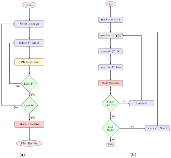
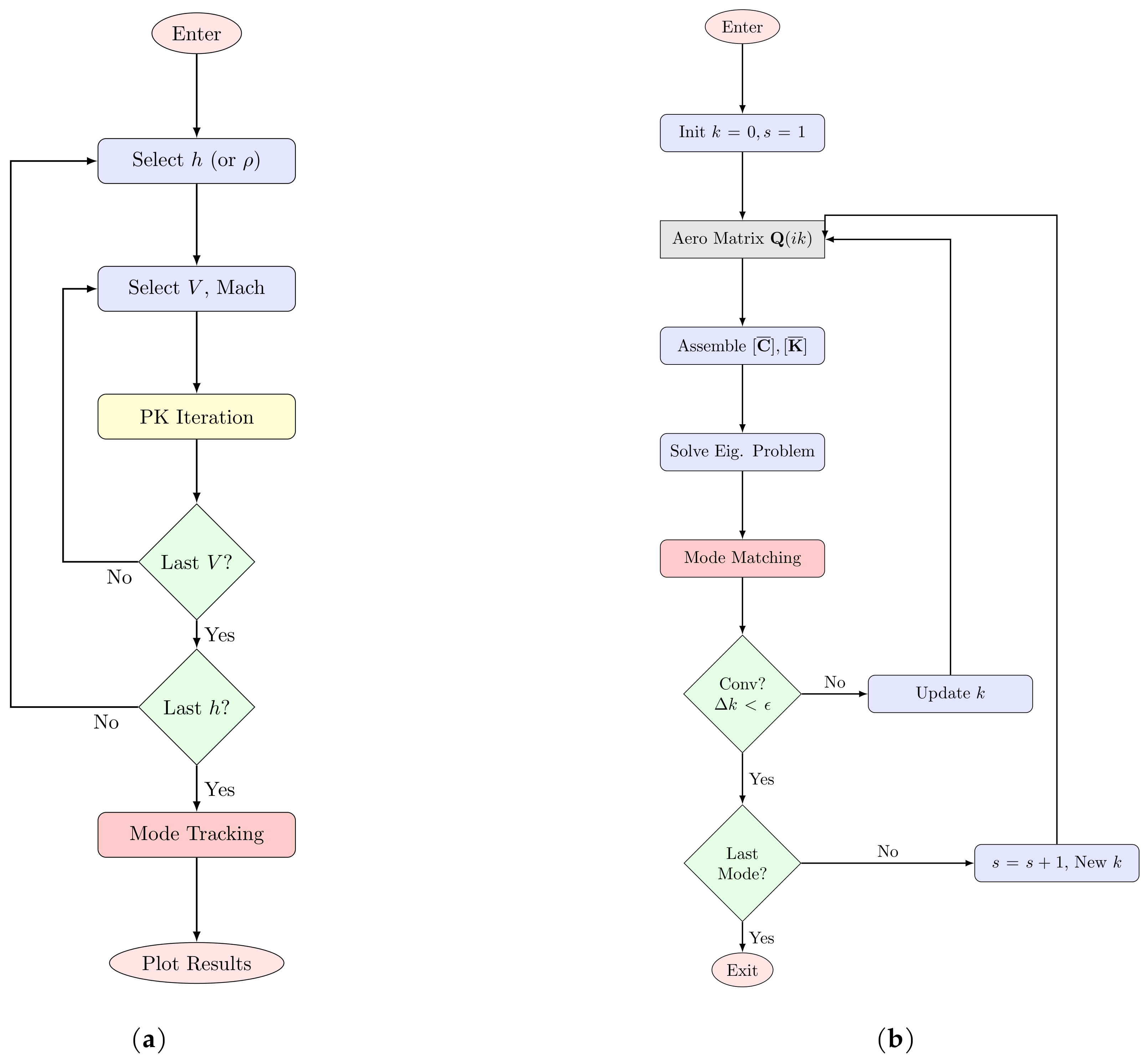
where . At each velocity step , the eigenvalues of matrix are solved iteratively until the reduced frequency converges. The complete iterative reduced-frequency state-matrix convergence algorithm is illustrated in Figure 1, where s denotes the mode index.
Figure 1.
Flowcharts of (a) the overall stability analysis and (b) the detailed p-k reduced-frequency iteration process, .
2.6. Time-Domain Wagner State-Space Formulation
In the Time-Domain Wagner formulation, unsteady wing lift and moment are modeled via Wagner’s indicial response function , where . Using Jones’ exponential coefficients (), aerodynamic memory is represented by internal state variables and :
Augmenting the structural modal displacement and velocity with lag states yields a unified linear first-order state-space system:
The eigenvalues of matrix directly yield the aeroelastic dampings and frequencies without reduced-frequency iteration.
2.7. Mode Tracking via the Modal Assurance Criterion
As the airspeed is swept, the frequencies of the individual aeroelastic branches approach one another and in places veer or cross. Sorting the eigenvalues by frequency at each step would then exchange the identities of two neighboring branches and produce discontinuous damping curves, so the branches are instead paired between consecutive steps by the Modal Assurance Criterion [31,32]. For the eigenvector obtained at airspeed and the eigenvector obtained at the preceding step,
which equals unity for identical shapes and zero for orthogonal ones. Each branch at the new speed is assigned to the branch at the previous speed with which its MAC is largest. The same procedure is applied to both solvers, so the V–g and V–f curves of the two formulations can be compared branch by branch.
2.8. Mode Identification and Participation
Two different measures are used in this study. The first describes the contribution of each motion component, including wing bending, wing torsion, and pylon rotation, while further resolving the pylon motion into the contribution of each propeller. The second identifies the underlying structural modes that combine to produce the instability. Although the two measures are related, they provide different information and are therefore not interchangeable; both are presented in the results.
2.8.1. Energy Shares
The first measure follows the modal kinetic-energy convention of standard finite-element practice [33] and assigns to each coordinate the quantity
where is the structural mass matrix. The aerodynamic mass is excluded, since it is a flow effect, not a physical inertia and would otherwise make the shares depend on airspeed through the weighting itself. The percentages quoted in the tables are the group sums , which add to by construction, and the per-propeller columns divide the pylon share among the individual units.
One consequence of Equation (22) is visible in below section tables and should be stated. The structural mass matrix is not diagonal: the static unbalance couples pylon pitch to wing bending and the product of inertia couples it to wing torsion. Because is symmetric, each off-diagonal term is shared equally between the two coordinates it connects. An individual share may therefore be negative under strong coupling, with the wing-torsion group exhibiting this behavior at the higher speeds reported below. These shares should thus be interpreted as indicators of coordinate participation, not as an exact partition of modal kinetic energy. For an exact decomposition, the normal-mode composition defined below is used.
2.8.2. Normal-Mode Composition
The second measure describes which structural modes are coalescing, flutter being classically understood as the merging of two or more structural modes [34,35]. The structural modes of the same discretization satisfy and are mass-normalized, . Expanding the aeroelastic mode shape on this basis gives
the last identity following from mass-orthogonality [36,37]. The fractions , normalized by their sum, are exact and contain no cross-terms, which is what makes them a reliable way of naming a flutter mechanism.
Both quantities depend on airspeed through and are therefore evaluated at two representative speeds. At the lowest speed in the sweep, the aerodynamic and gyroscopic effects are negligible, and the resulting branches closely represent the underlying structural modes. Mode identification is performed at this condition and maintained through the airspeed range using MAC-based tracking. The same quantities are then evaluated at the flutter speed of each unstable branch using the corresponding eigenvector, which is also used to generate the mode-shape and orbit plots. This second evaluation provides the basis for identifying and interpreting the flutter mechanism.
3. Results and Discussion
This section presents the multi-propeller results in three parts. The first part focuses on model verification and validation. The propeller model is first verified independently by comparing its unsteady aerodynamic derivatives with published data and NASTRAN results, and its isolated whirl-flutter boundary is then validated against experimental data. The assembled wing–propeller system is subsequently validated by comparing its natural frequencies and stability boundaries with available reference results. The second part presents the results for the three four-propeller DEP configurations considered in this study. For each configuration, the frequency-domain p–k method is compared with the time-domain Wagner method, followed by an examination of the mode shapes and whirl orbits to identify the physical mechanisms associated with the observed instabilities. Finally, the third part presents a parametric study in which the propeller sizes are varied while keeping the total disk area constant. The resulting changes in the whirl-flutter stability boundaries are then evaluated to assess the influence of propeller size distribution. All three distributed propeller configurations use the same wing, nacelle model, and total propeller disk area. The only difference is the spanwise distribution of the propeller masses and inertia, therefore isolating the effect of propeller placement along the span.
3.1. Verification and Validation of Propeller Whirl Flutter
To establish the mathematical model prior to analyzing multi-propeller DEP wings, the Houbolt–Reed propeller aerodynamic derivative formulation and isolated whirl flutter solver are verified against benchmark literature data, experimental measurements, and MSC NASTRAN solver output.
The reference propeller model investigated by Bennett and Bland [38] is selected for derivative verification. Table 1 present the comparative validation of the primary aerodynamic derivatives against values from [23], Xu [25], the present analytical Houbolt–Reed formulation, and MSC NASTRAN prop.f.
Table 1.
Comparison of the propeller aerodynamic derivatives.
As shown in Table 1, the present analytical Houbolt–Reed formulation matches the NASTRAN prop.f numerical code and published literature within less than 0.2% relative error across all blade angles, confirming the mathematical accuracy of the integrals and used in the upcoming DEP analysis.
Next, to verify the complete propeller whirl flutter solver, predictions are compared with experimental wind tunnel measurements from NASA TN D-1807 [38] across 12 test cases under two pivot location, (Cases 1–6) and (Cases 7–12), in Table 2.
Table 2.
Comparison of isolated propeller whirl-flutter speeds and frequencies for NASA TN D-1807 case.
When Table 2 is investigated, the present model under-predicts the flutter speed in all cases, by 12% on average, and over-predicts the flutter frequency in the same twelve, by 9%. A model that predicts flutter early and at a slightly high frequency errors on the safe side, which is the preferable direction for a preliminary design tool. A clear difference is observed between the two pivot configurations. For the short-pivot (Cases 1–6), the reference study provides more accurate predictions, with a mean speed error of 6% compared with 11% for the present model, and remains closer in all six cases. For the long-pivot (Cases 7–12), however, the trend is reversed, with mean errors of 15% for the present model and 24% for the reference study. Overall, the level of agreement is considered satisfactory for the intended comparative analysis.
3.2. Coupled Wing–Propeller Model and Verification
Following the validation of the isolated whirl-flutter model, the coupled structural model is based on the flexible wing with integrated propeller–nacelle units presented in Ref. [25]. The geometric and structural properties of the cantilevered wing, together with the baseline parameters of the mounted propeller unit, are summarized in that reference. A single propeller is placed at the inboard station m.
Table 3 lists the branches identified at the lowest sweep speed, where the bending, torsion and pylon shares are obtained from the modal kinetic energy and sum to 100%. Two branches are pylon dominated, the backward and forward whirl modes at 5.57 and 7.00 Hz, and the remaining four are wing modes.
Table 3.
Mode identification and MKE participation of the physical branches for validation case.
The coupled framework is validated against Ref. [25] for the same configuration. The resulting stability boundaries are summarized in Table 4, while the corresponding V-g and V-f diagrams, together with the quasi-steady aerodynamic comparison, are provided in the authors’ previous study [39]. Both solvers reproduce the reference flutter speeds closely and, more importantly, predict the same instability mechanisms in the same sequence. The time-domain formulation matches the reference wing-flutter speed exactly at 174 m/s, while the p-k solution differs by only 1.2%. Both forward-whirl predictions remain within 4% of the reference value. The predicted divergence speed is 149 m/s for both formulations, a 1.9% discrepancy relative to the reference study.
Table 4.
Decomposition of each unstable eigenvector at its flutter speed onto the structural normal modes for validation case.
Although the branch that crosses at 179 m/s is labeled forward whirl, the label records its character at the lowest sweep speed, where the branch is pure yaw motion, and the tracking then carries the name upward. By the flutter speed, it has migrated into the wing, its decomposition giving 87.2% first bending against only 8.9% yaw (Table 4). The instability is therefore wing dominated. The same behavior is reported by [25], who finds that forward whirl flutter can occur with rigid blades through interaction with a wing mode, contrary to the expectation drawn from propellers on rigid mounts.
3.3. Extension to Four Propellers Cases
Three distinct Distributed Electric Propulsion (DEP) configurations built on the baseline [25] wing are investigated under conserving total disk area:
where m is the baseline radius. Disk-loading-preserving scaling laws, , , and , ensure that total propeller mass is conserved across all configurations at kg. The pylon overhang scales with the unit in the same way, in proportion to k, with a baseline value of m, so that each propeller keeps its baseline pivot-to-disk proportions.
The exponent in is a modeling choice; geometric similarity would instead yield , combining disk-area redistribution with increased mass. The adopted scaling ensures constant installed disk area and mass through , with the static moment and inertia scaling accordingly with length and length squared.
- Configuration 1: Four equal baseline propellers ( m) located at m.
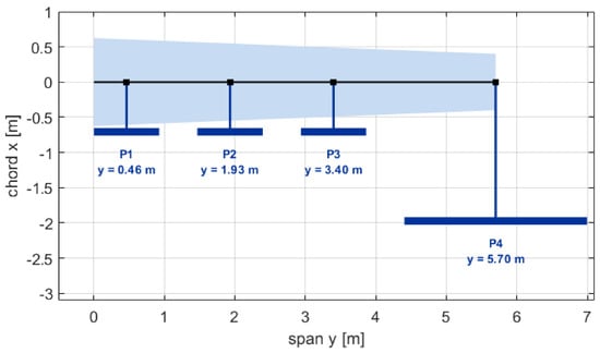
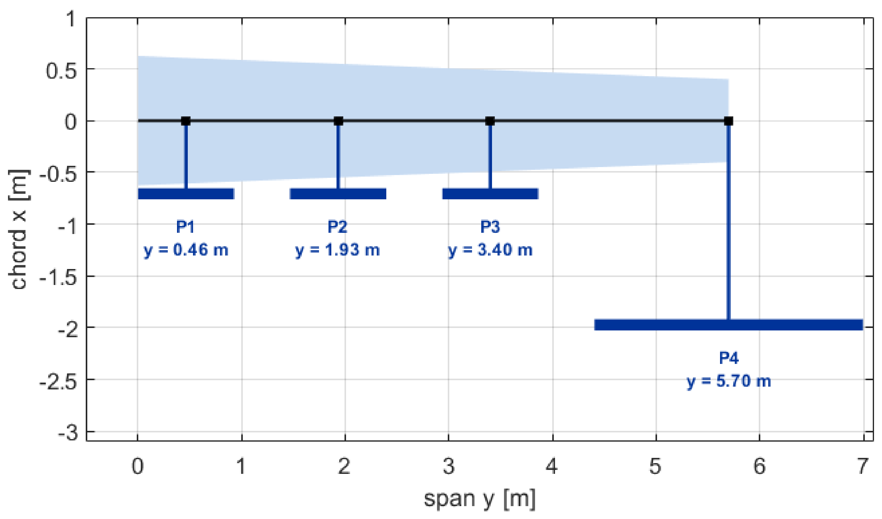
- Configuration 2: One large mid-span propeller ( m) at m, with three small propellers ( m) at m.
- Configuration 3: One large tip propeller ( m) at m (tip), with three small propellers ( m) at m.
Table 5 summarizes the scaled mechanical properties for Small (), Baseline (), and Large () propeller units.
Table 5.
Propeller geometric and inertial properties for baseline (), large (), and small () scale factors.
Because total disk area and hence total propeller mass are held fixed, any differences between the three layouts are due to the spanwise distribution of propeller size, mass, and inertia rather than to changes in the installed propulsive capability. Configuration 1 distributes four equal baseline units evenly along the span, while Configurations 2 and 3 replace them with one large unit () and three small ones (), placed inboard and at the tip, respectively. Whirl branches are classified as forward or backward from the sign of the net pylon angular momentum, .
The three configurations that follow are predictions of the present model. What the validation above establishes is the formulation itself, on the isolated propeller and on the single propeller–wing, from which these layouts are assembled without further change.
3.3.1. Configuration 1: Four Equal Propellers
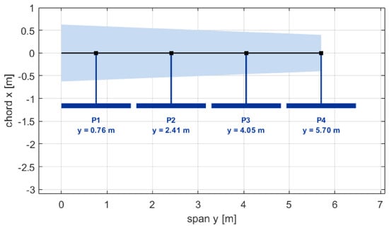
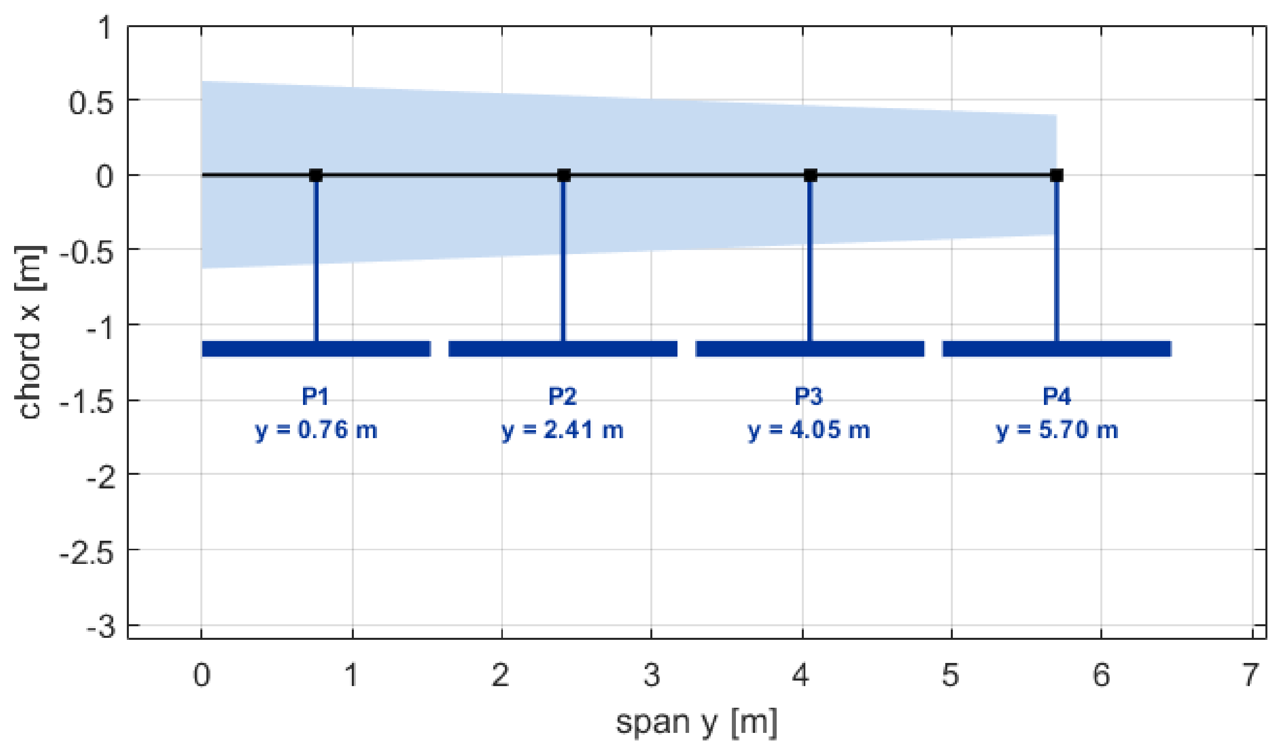
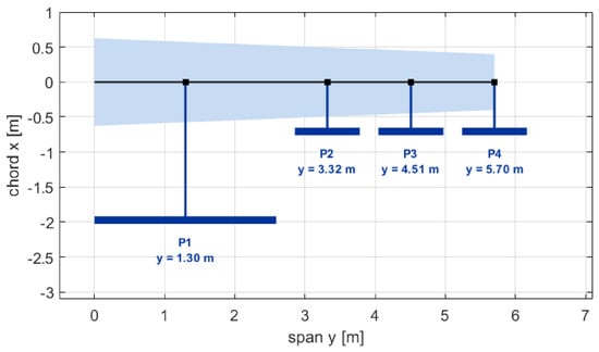
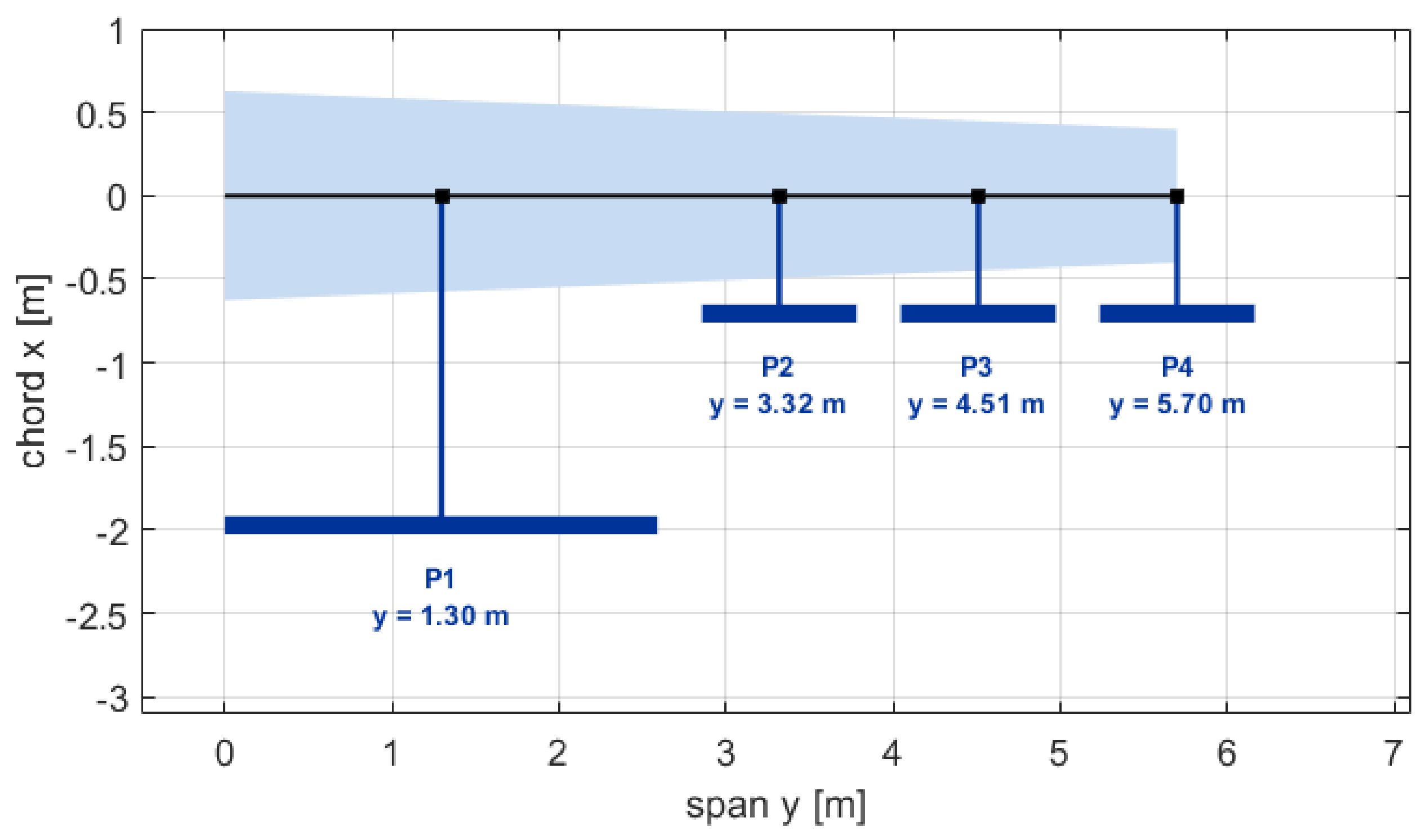
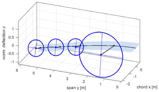
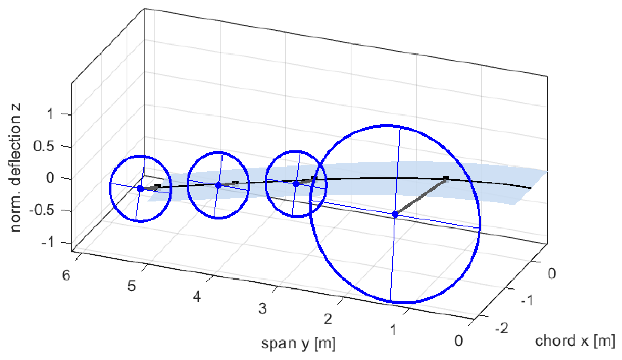
For this configuration, four baseline units are spaced evenly along the span; Figure 2 shows the planform view of the propeller–wing.
Figure 2.
Planform view and propeller locations for Configuration 1: equal propellers ().
The aeroelastic system is solved at the lowest speed of the sweep, where the aerodynamic and gyroscopic terms are negligible, and Table 6 lists the resulting frequencies, in which the bending, torsion, and pylon shares are obtained by the modal kinetic-energy convention of finite-element practice [33] and sum to 100%. The four branches at 7.00 Hz are the yaw modes of the four pylons. They share a single frequency and a single eigenspace, therefore division of the pylon share among propellers is arbitrary.
Table 6.
Mode identification and MKE participation of the physical branches for Configuration 1.
In Table 6, the first wing bending is almost pure wing motion (82.3% bending, 3.8% pylon), whereas the first wing torsion already carries 33.9% of its energy in the pylons. The propeller pitch degree of freedom is coupled to wing torsion through the static and inertial cross-terms. The four branches at exactly 7.00 Hz are the opposite case, 100% pylon, with no bending or torsion content, because the yaw coordinate has no inertial or elastic coupling to the wing and therefore remains at the nominal mount frequency. The pitch-related branches spread over a much wider band, from 6.06 to 34.95 Hz, and the most strongly coupled of them have substantial wing content of 34.9% torsion for backward whirl 3 and 27.1% for forward whirl 5.
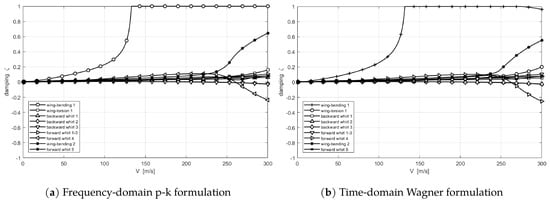
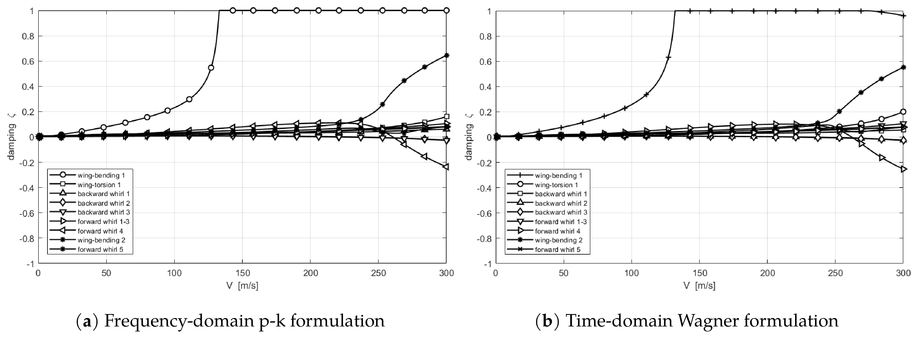
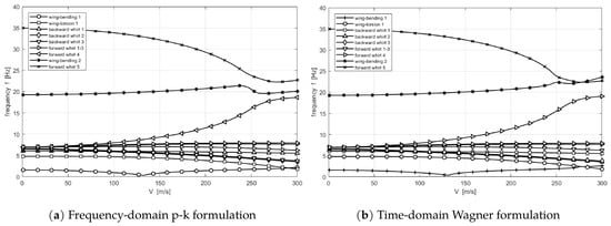
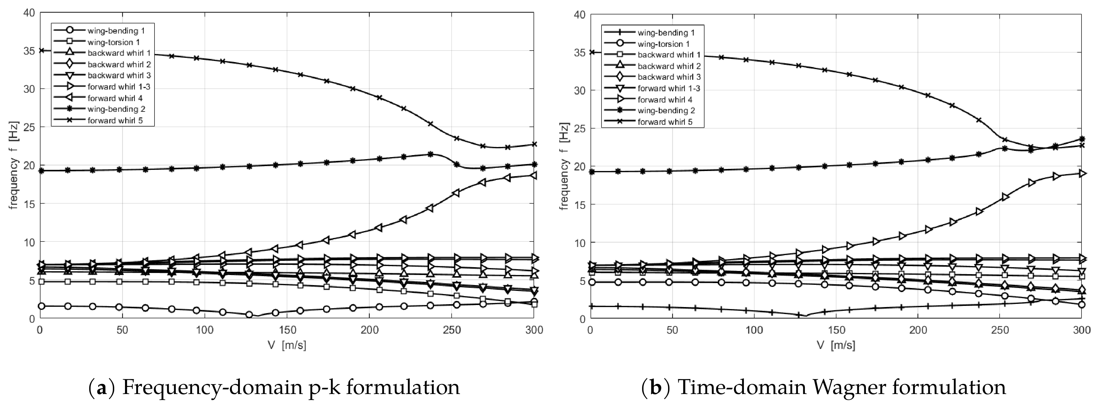
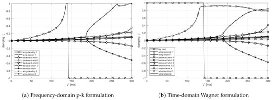
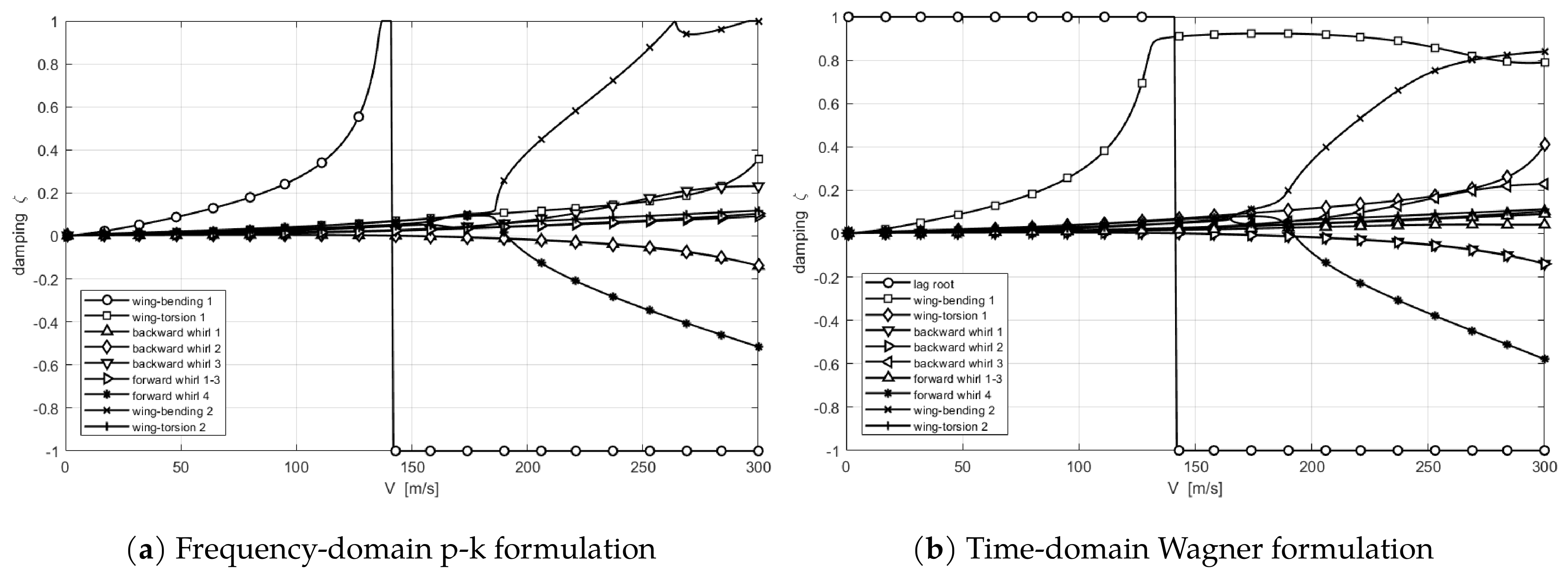
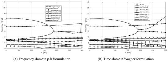
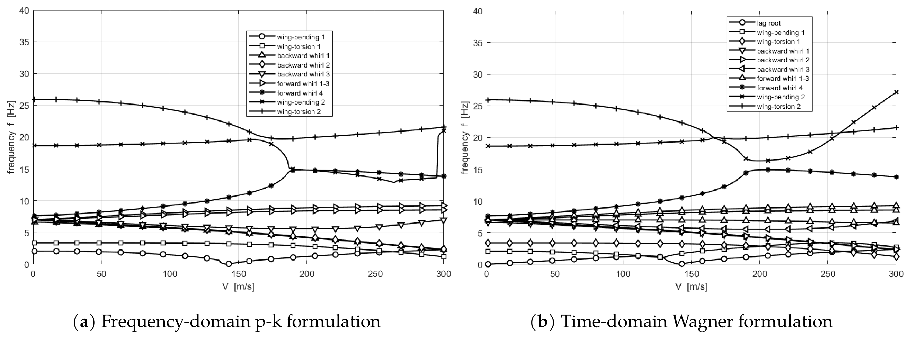
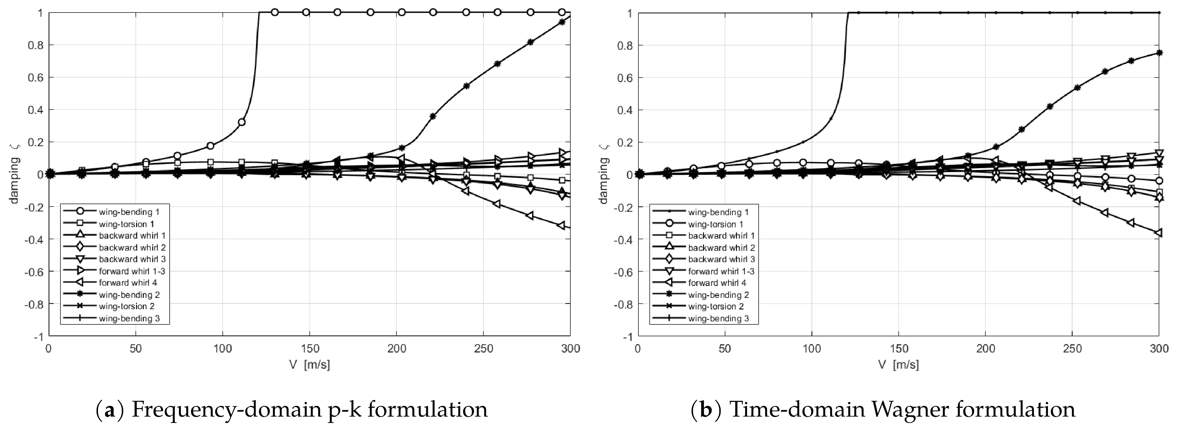
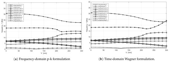
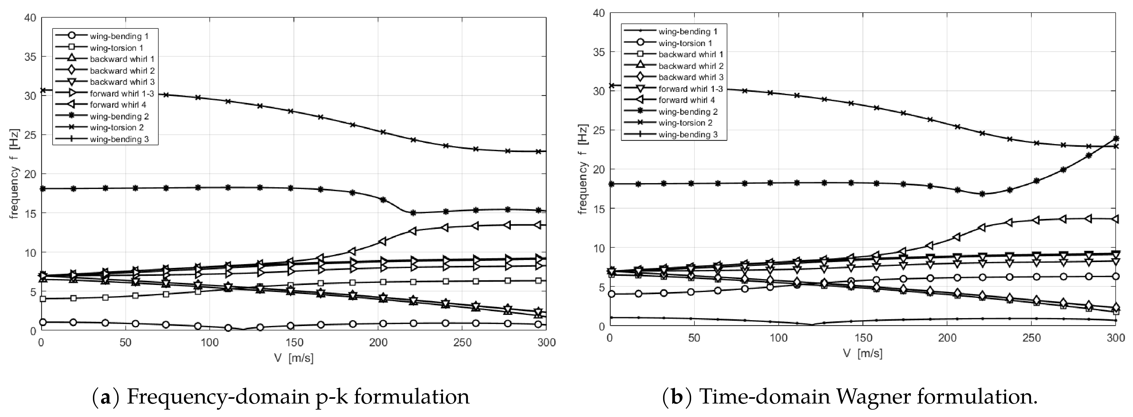
Next, the flutter analyses are performed with frequency- and time-domain methods and compared with each other (Figure 3 and Figure 4). Eight branches, namely, two wing-bending modes, the first wing-torsion mode, and eight propeller whirl branches have been found. Three of the forward branches coincide over the lower part of the sweep and share one legend entry, separating only as the gyroscopic splitting opens. They cluster near the mount frequency of 7 Hz at low speed and spread apart as airspeed rises, backward branches falling and forward branches rising under the gyroscopic terms. The count is three backward and five forward, not four of each, and the imbalance has a physical origin. Pylon pitch is strongly inertia-coupled to wing torsion, which displaces one pitch branch all the way to 35 Hz and leaves its would-be backward partner, backward whirl 3 at 6.06 Hz, with less than half of its energy in the pylons. The 35 Hz branch falls in frequency across the sweep, which under the usual frequency-trend rule would indicate backward whirl. However, the fall is an approach to the second wing-bending branch from which the two roots veer away rather than cross [40], and the orbit sense confirms that the branch is forward.
Figure 3.
Damping ratio versus airspeed plots for Configuration 1.
Figure 4.
Frequency versus airspeed plots for Configuration 1.
Three oscillatory instabilities have been computed and listed in Table 7: these are backward-whirl crossings at 221 and 234 m/s and a forward-whirl crossing at 263 m/s, which are the highest flutter speeds of the three layouts. The p-k solution gives 219, 230, and 261 m/s at 4.84, 4.51, and 17.18 Hz for the same three branches, within 1.7% in speed and 1% in frequency of the time-domain values, and in the same order.
Table 7.
Decomposition of each unstable eigenvector at its flutter speed onto the structural normal modes for Config. 1.
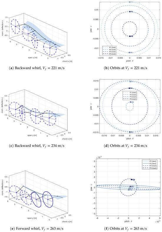
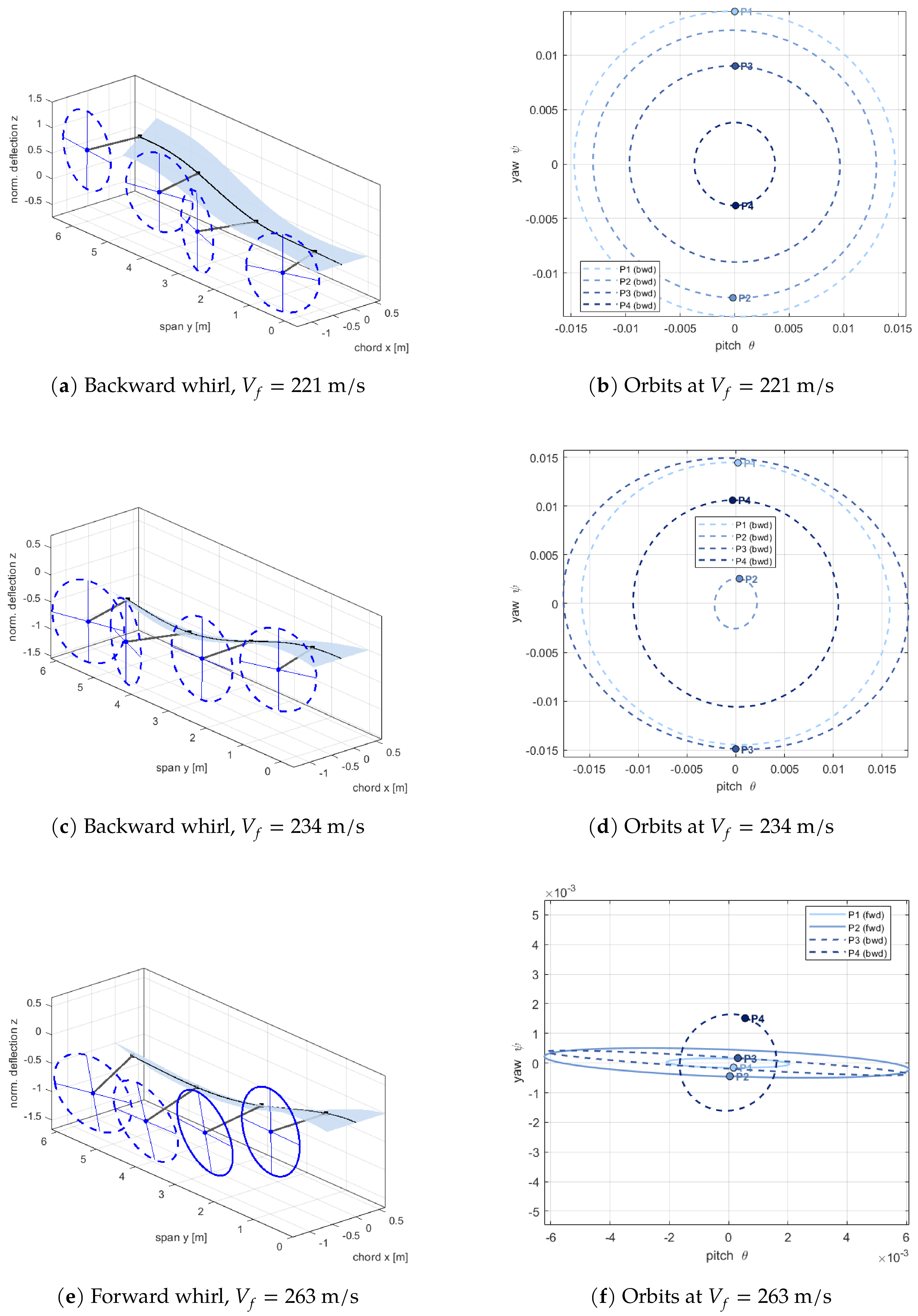
The mode shapes and orbits at the three crossings are plotted in Figure 5. Each propeller disk and orbit is drawn with the line style of its own whirl sense, dashed for backward and solid for forward. The three mode shapes divide into two kinds. In the backward-whirl modes (Figure 5a,c), the wing deflects in a first-bending shape, and all four propellers trace near-circular orbits of comparable radius, the near- pitch-yaw phase of a classical whirl cone. No single unit dominates, as identical propellers require. The forward-whirl mode at 263 m/s in Figure 5e is visibly different, and the orbits collapse into flat ellipses aligned with the pitch axis and shrink by almost an order of magnitude, while the wing deflection grows and depicts clear torsion. The pylons are no longer whirling so much as pitching in step with a wing mode. That branch is 100% pylon at rest (Table 6), but by its flutter speed, only 48.1% of the eigenvector remains in the pitch and yaw modes and 42.7% has moved into the first two wing-bending modes, which is what the orbit panel shows directly.
Figure 5.
Unstable modes of Configuration 1 at the three crossings: three-dimensional wing and propeller deflection (left) and pitch–yaw orbits of all four propellers (right).
The two backward-whirl modes are almost purely propeller motion. At 221 m/s, 56.0% of the eigenvector projects onto the 6.68 Hz pitch mode and a further 41.1% onto the 7 Hz yaw modes. The 234 m/s mode is similar in kind but spreads its pitch content over two modes, 42.0% at 6.44 Hz and 21.6% at 6.09 Hz, with 34.0% in the yaw modes. The forward-whirl mode at 263 m/s is different in kind. Its pylon content has fallen to 48.1%, and 42.7% of the eigenvector now lies in the first two wing-bending modes, so the wing carries almost half of the motion [34,35].
3.3.2. Configuration 2: Large Inboard Propeller
For this configuration, the large propeller is moved to an inboard station at approximately 23% of the semispan, and the three remaining units are scaled down to preserve the total disk area, shown in Figure 6.
Figure 6.
Planform view and propeller locations for Configuration 2: large inboard propeller ().
The spectrum for Configuration 2 in Table 8 divides much as in Configuration 1, but the large inboard unit leaves two distinct points. The first is on wing torsion 1 at 3.37 Hz, whose 21.1% pylon share is almost entirely P4 (20.8%): the pitch degree of freedom of the large propeller is bound into wing torsion from the outset, and this is where its backward whirl branch has gone, and only seven whirl branches survive. The second is forward whirl 1 at 7.01 Hz, which is 99.9% P4 and 100% pylon, an entirely isolated mode of the large unit that neither couples to the wing nor mixes with the small propellers. Between these two extremes the small-propeller branches cluster closely between 6.61 and 7.64 Hz, five of them within 0.05 Hz of the nominal mount frequency, so the whirl family here spans less than 1 Hz against the 6–35 Hz spread of Configuration 1. Only wing torsion 2 at 25.94 Hz carries appreciable distributed pylon energy. In addition, the lag root is a pure wing mode, 54.7% bending and 45.3% torsion with no pylon content at all, which is a static divergence of the wing.
Table 8.
Mode identification and MKE participation of the physical branches for Configuration 2.
Instabilities appear considerably earlier than in Configuration 1 and shown in Table 9. The time-domain solution gives backward-whirl crossings at 149 and 153 m/s and a forward-whirl crossing at 192 m/s, so the lowest oscillatory boundary is about a third below the corresponding Configuration 1 value (Figure 7). The p-k solution produces the two backward-whirl branches that are obtained at 149 and 153 m/s and at 5.11 and 4.95 Hz, which are the time-domain values to the resolution of the sweep, and the forward-whirl branch at 192 m/s and 14.79 Hz against 14.65 Hz, a difference of 1.0% in frequency at an identical speed. For this configuration the two formulations therefore agree on every oscillatory boundary to within the 1 m/s step of the sweep, and to better than 1% in frequency.
Table 9.
Decomposition of each unstable eigenvector at its flutter speed onto the structural normal modes for Config. 2.
Figure 7.
Damping ratio versus airspeed plots for Configuration 2.
Moving the large propeller inboard and shrinking the three outboard units splits the whirl family into two recognizable groups, the three small units P1–P3 and the large unit P4, clearly visible in both solutions in Figure 8. Only the forward branch of the large propeller survives as a distinct whirl mode. However, its backward counterpart never forms: the pitch of the large unit is so strongly inertia-coupled to wing torsion that its motion is absorbed into the torsion family before the sweep begins, the first torsion mode at 3.37 Hz already carries 21% of the large unit’s pylon energy, and the 25.94 Hz branch carries another distributed share (Table 8).
Figure 8.
Frequency versus airspeed plots for Configuration 2.
One feature belongs to the time-domain solution alone is a purely real aerodynamic lag root that crosses 142 m/s and is a divergence instability. The p-k method contains no lag states and yet it reaches the same boundary with the first wing-bending branch loses damping at 142 m/s with the frequency collapsed to 0.01 Hz. The two formulations therefore agree on the divergence instability, as a real aerodynamic lag root in the time domain and as a frequency collapse of the bending branch in the frequency domain.
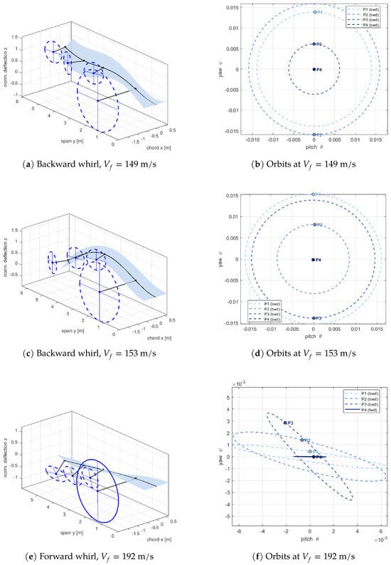
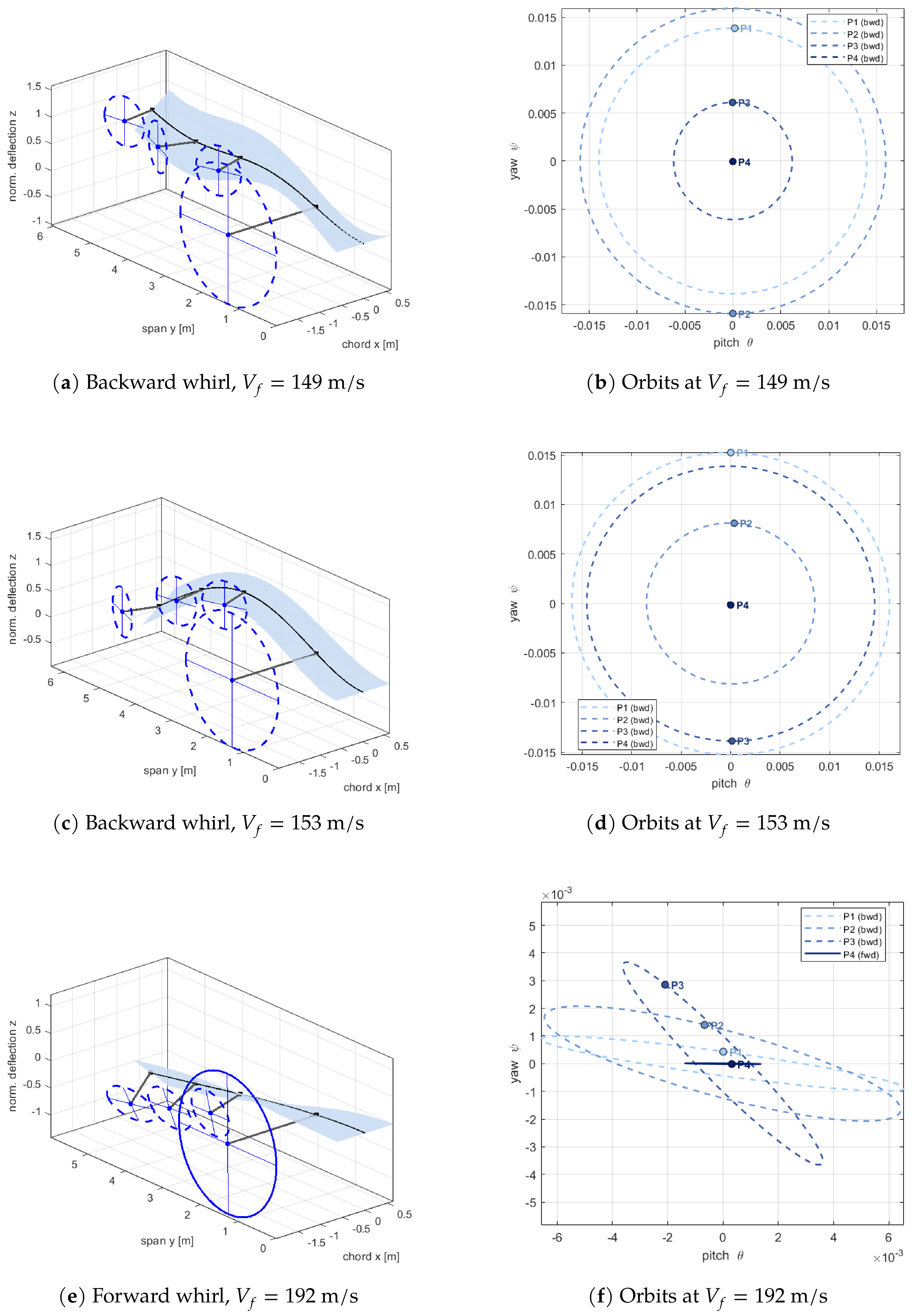
The whirl mode at 149 m/s (Figure 9a) is driven by the small outboard propellers, not by the large inboard unit. The orbit panel makes the point clearly: P4 sits essentially at the origin while P1 and P3 trace wide circles. Given that P4 carries sixty times the pitch inertia of a small unit, even a modest orbit would have dominated that it contributes almost nothing is a placement effect, since at 22.8% semispan, the wing simply does not move enough to drive it. Reading the orbit radii and weighting each by its own inertia reproduces the tabulated pylon shares to within about two percentage point and shows a check on the participation calculation.
Figure 9.
Oscillatory unstable modes of Configuration 2: three-dimensional wing and propeller deflection (left) and pitch–yaw orbits (right).
The second backward-whirl mode at 153 m/s (Figure 9c) demonstrates a similar orbit pattern. The 192 m/s branch needs a closer look (Figure 9e). At rest, it is a small-propeller whirl mode, with 62.1% of its energy in the pylons (Table 8), and its frequency climbs from 7.64 to 14.65 Hz across the sweep. By the flutter speed, the balance has reversed. The decomposition in Table 9 gives 33.7% first bending and 18.7% second torsion against 38.2% pylon pitch, so the wing now carries more of the motion than the pylons. Participation here is set by the coupling between modes instead of by their separation in frequency as reported in Ref. [35].
Table 9 supports the aforementioned interpretation and provides a clearer picture of the modal composition. The two backward-whirl modes are dominated by the small-propeller group: the 149 m/s branch consists of 50.4% P1–P3 pitch together with 25.8%, 19.5%, and 3.8% of the 7 Hz P1–P3 yaw modes, and the 153 m/s branch consists of 56.8% pitch with 20.2%, 16.7% and 5.7% yaw. Neither mode has significant wing or large-propeller participation. In contrast, the lag-root crossing at 142 m/s is almost entirely associated with fundamental wing bending, shown in Figure 10. Its decomposition gives 99.6% of the first bending mode, and the energy split at the crossing agrees, with 94.8% of the modal kinetic energy in bending and 4.8% in torsion, only 0.4% remaining in the pylons and no more than 0.1% in any individual propeller.
Figure 10.
Divergence instability at m/s for Config. 2.
3.3.3. Configuration 3: Large Tip Propeller
The final layout, whose planform is shown in Figure 11, keeps the propeller sizes of Configuration 2 but relocates the large unit to the wingtip, where the bending and torsion mode shapes reach their maximum.
Figure 11.
Planform view and propeller locations for Configuration 3: large tip-propeller ().
Table 10 lists the spectrum at the lowest sweep speed, where the bending, torsion, and pylon shares sum to 100% and the P1–P4 columns divide the pylon share among the propellers. Whirl branches are numbered at a reference speed inside the sweep, where the gyroscopic terms have separated the branches that coincide at rest, so the frequency column does not increase monotonically. The four branches between 7.00 and 7.01 Hz are the yaw modes of the four pylons. They are not exactly degenerate here, since the unequal inertias split them slightly and fix the basis, so forward whirl 2, with 97.0% of its pylon energy in P4, is the yaw mode of the tip unit. Flutter speeds and mechanisms follow in Table 11.
Table 10.
Mode identification and MKE participation of the physical branches for Configuration 3.
Table 11.
Decomposition of each unstable eigenvector at its flutter speed onto the structural normal modes for Config. 3.
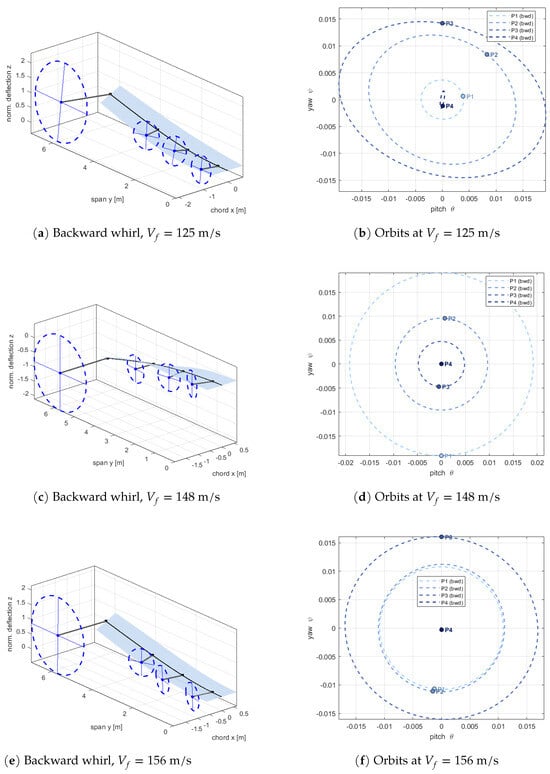
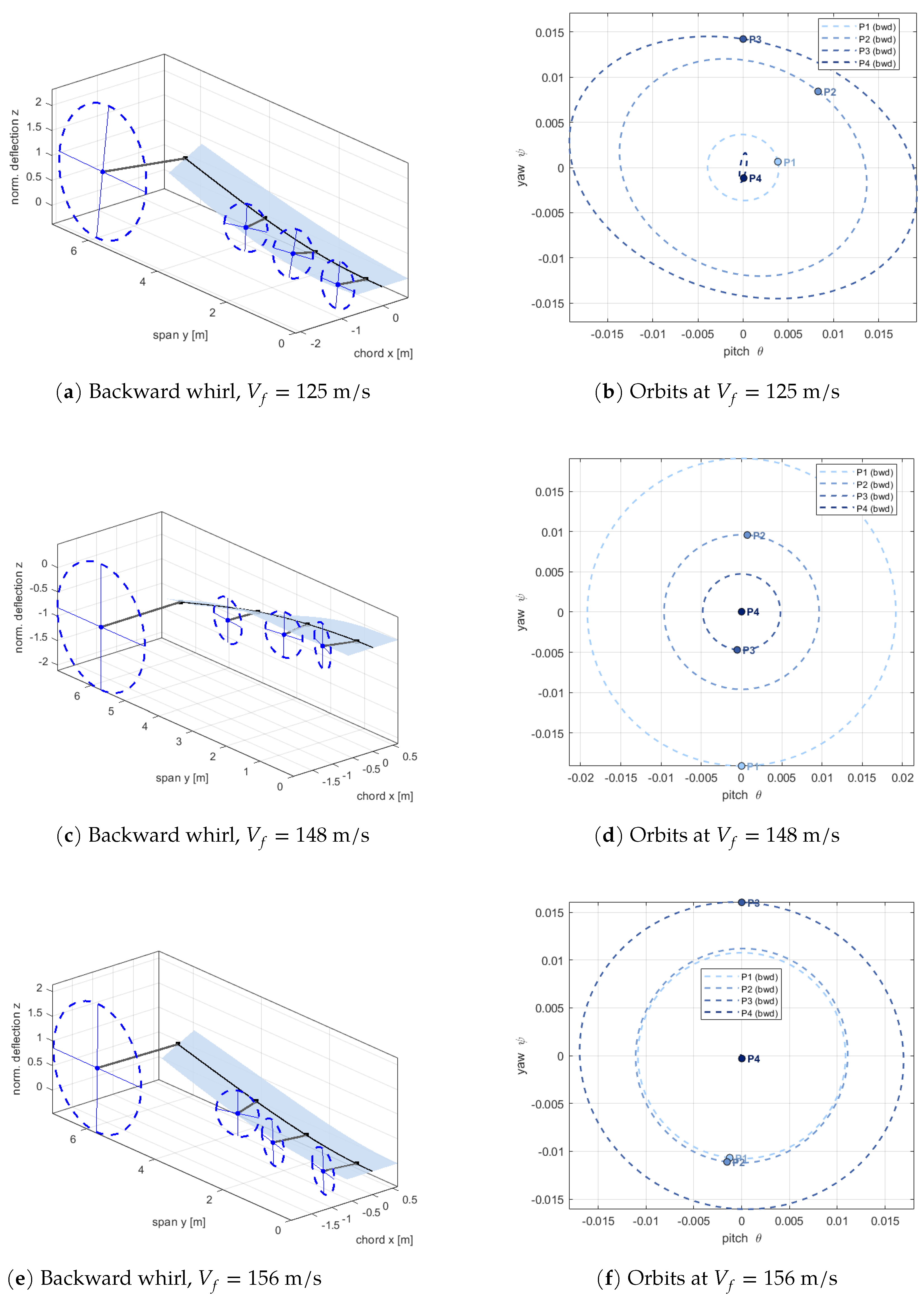
Relocating the large propeller to the wingtip produces the least stable layout of the three. The time-domain solution gives backward-whirl crossings at 125, 148, and 156 m/s and two further instabilities at 225 and 230 m/s. The governing whirl speed of 125 m/s is little more than half the Configuration 1 value and some 16% below Configuration 2, despite identical total disk area and propeller mass (Figure 12 and Figure 13).
Figure 12.
Damping ratio versus airspeed plots for Configuration 3.
Figure 13.
Frequency versus airspeed plots for Configuration 3.
The p-k solution gives the same picture quantitatively. Every branch agrees to within 1.7% in speed and 0.7% in frequency, and the ordering is identical. Overall, placing the largest rotor inertia where the bending and torsion mode shapes reach their maxima maximizes the inertial and gyroscopic coupling between pylon and wing and that is the mechanism behind the reduced margin.
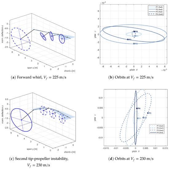
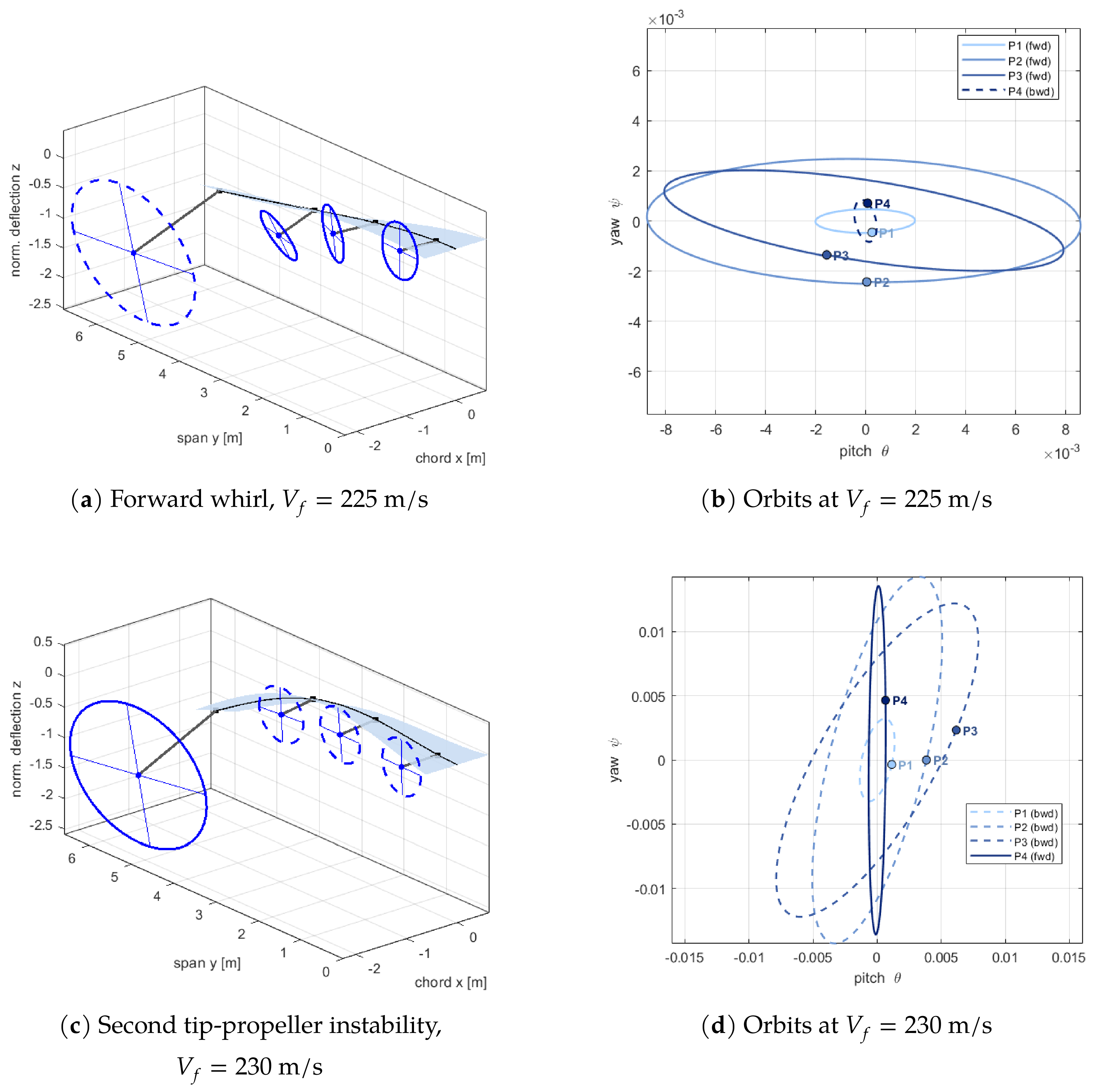
The pair of branches at 225 and 230 m/s exchanges character across the sweep, and this exchange runs in both directions. The 225 m/s branch is a small-propeller whirl mode, since it carries 99.8% of its energy in the pylons but only 1.3% of that share in P4, whereas the 230 m/s branch is wing torsion, with 54.9% torsion and 39.9% bending and almost no pylon content. By their respective flutter speeds, the roles have been reversed. The 225 m/s branch has migrated into the wing and reaches 79.3% bending, its pylon share having fallen to 31.6%, while the 230 m/s branch has become 76.3% pylon, of which 73.9% belongs to the tip propeller alone. The decomposition in Table 11 shows the same behavior. The 225 m/s branch is 50.7% first torsion and 19.1% second bending with only 12.3% P4 yaw, whereas the 230 m/s branch is 72.5% P4 yaw with 18.2% first bending. It is therefore the wing-torsion branch, and not a whirl branch, which ends as the tip-propeller motion. This veering [40] is already visible in the V-f diagram and is also what drives the DOF-group split outside its physical range at both crossings, the torsion share becoming negative in each case. The exchange is unique to this layout, since only here does the large propeller sit where the torsion shape functions attain their maximum.
The same exchange is shown as a continuous function of airspeed in Figure S1 of the Supplementary Materials, the composition of each branch being obtained by projecting the tracked eigenvector onto the mass-normalized structural modes. The corresponding curves for Configurations 1 and 2, which show that the behavior is not generic, are given in Figure S2a,b.
A comparison with Configuration 2 isolates the effect of spanwise station. In both layouts, the isolated whirl mode of the large propeller, which carries essentially all of its pylon energy in P4 at rest, remains stable throughout the sweep, so the large unit never destabilises through its own whirl motion. The difference lies in the wing branches. At the inboard station, the first torsion mode absorbs part of the large propeller from the outset and remains stable, whereas at the tip, the same mode becomes unstable at 230 m/s and arrives at the crossing with 73.9% of the pylon energy in P4. The tip propeller thus contributes to the instability by moving with the wing, without rotating relative to it. Since the propeller properties and the mount frequency are identical in the two cases, this change is attributable solely to the spanwise location of the unit.
The governing branch at 125 m/s is itself already strongly coupled to the wing at its flutter speed, its decomposition being 44.5% first torsion against 24.7% P1–P3 pitch, with a further 6.8% drawn from the tip-propeller yaw mode. This is the clearest difference from Configuration 2, where the corresponding branch remains almost purely a small-propeller mode.
The three backward-whirl modes (Figure 14) reproduce the orbit pattern of Configuration 2, with the small units describing large circles and the large unit remaining near the origin. The wing deflection, however, differs: the tip amplitude is large, indicating that the tip propeller is displaced by the wing motion without rotating relative to it. The orbits also show the identity exchange described above directly. At 225 m/s (Figure 15a), they form wide, flat ellipses aligned with the pitch axis, whereas at 230 m/s (Figure 15c), the tip-propeller orbit is a narrow ellipse aligned with the yaw axis, so the transition from pitch-dominated to yaw-dominated motion is evident from the orbit geometry alone.
Figure 14.
Backward-whirl instabilities of Configuration 3, the 125 m/s crossing being the lowest flutter speed of all three configurations: three-dimensional wing and propeller deflection (left) and pitch–yaw orbits (right).
Figure 15.
The exchanging pair of Configuration 3, a forward-whirl branch at 225 m/s, and a wing-torsion-coupled mode of the large tip propeller at 230 m/s: three-dimensional wing and propeller deflection (left) and pitch–yaw orbits (right).
Taken across the three layouts, the governing speed falls from 221 m/s for the evenly distributed arrangement to 142 m/s for the inboard large propeller and 125 m/s for the tip-mounted one, a reduction of some 43% at identical total disk area and propeller mass. The lowest oscillatory crossing follows the same ordering, 221, 149, and 125 m/s, the inboard layout reaching its limit by static divergence before any flutter branch crosses. Both methods reproduce this ordering and agree on every oscillatory boundary to within 1.7% in speed and 1.0% in frequency. The mechanism is consistent throughout: concentrating rotor inertia where the bending and torsion mode shapes are largest maximizes the inertial and gyroscopic coupling between pylon and wing. The clearest single demonstration is the first wing-torsion mode, which absorbs part of the large propeller at either station but remains stable when the unit is inboard, whereas at the tip it becomes unstable at 230 m/s and arrives at the crossing with 73.9% of its pylon energy in the tip unit alone. The isolated whirl mode of the large propeller itself stays stable in both layouts, so the large unit destabilizes the wing not by whirling relative to it but by being carried with it. For distributed electric propulsion wings, the spanwise placement of propeller mass and inertia is therefore as strong a whirl-flutter design driver as the installed disk area.
3.4. Variation of Propeller Size Distribution
The three configurations examined in the preceding sections are, in fact, three discrete points of a continuous family. All of them possess the same installed disk area and the same total propeller mass, and they differ only in the manner in which this area is distributed along the span. A continuous parameterization is therefore introduced to establish the overall trend and determine whether the observed stability ordering persists for other propeller size ratios or whether the tip-mounted configuration represents the most critical case within this family. Accordingly, the propeller distribution is varied continuously, and the aeroelastic analyses are performed for each configuration.
A single parameter, the size ratio of the large unit, is swept from to with an increment of . The three remaining units are then obtained from the disk-area constraint that has already been employed for Configurations 2 and 3 so that the installed disk area remains identical at every point of the sweep. Note that the two end points of the sweep correspond to configurations that have already been presented: recovers four equal propellers, that is, Configuration 1 exactly, whereas gives the size split of Configurations 2 and 3.
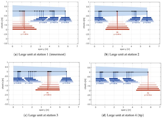
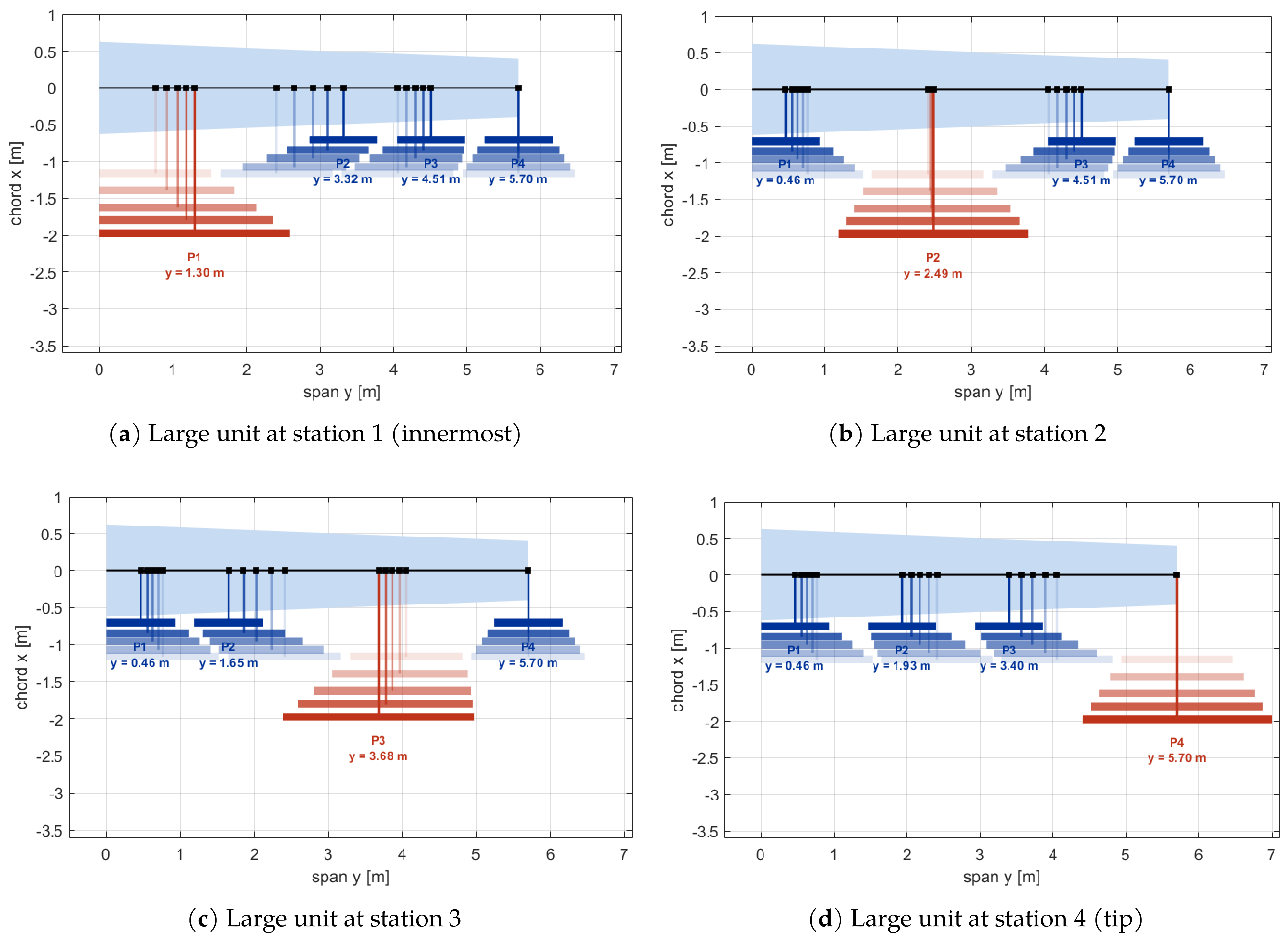
In order to separate the effect of concentration from that of placement, the sweep is repeated four times, once for each spanwise station of the large unit. Within each case, the propellers are positioned according to the same rule: the innermost disk is placed just clear of the root, the outermost one is pinned at the tip, and the remaining span is shared equally between the three gaps,
where the tip disk is counted only once, since clearance is required on its inboard side alone. At , this rule reproduces the Configuration 1 stations m exactly, and therefore the left-hand end of every curve constitutes a validation point against the 221 m/s reported in Table 7.
The planform evolution produced by the disk-area concentration sweep is shown in Figure 16, where five steps (, , , , and ) are superimposed on a single planform for each station, with the opacity being increased with so that the progression can be followed. The large unit is drawn in red and the three small units in blue, the disks are seen edge-on at their respective pivot planes, and the annotated stations correspond to the final configuration at . When this figure is investigated, three effects are seen simultaneously, every outline carrying the same installed disk area. Firstly, the large disk grows from m to m, while the three small ones are reduced to m, so that area is transferred from three units. Secondly, every station is displaced, since the spacing rule of Equation (25) depends upon the radii themselves. Thirdly, each disk bar migrates forward as its own pivot arm is scaled with it, from a common value of m at to m for the large unit and m for the small ones at .
Figure 16.
Planform view of the disk-area concentration sweep across the values with opacity increasing along .
Also, the minimum clearance between adjacent disks increases monotonically with , from m at to m at for the tip-mounted case, since the three small units are reduced in size more rapidly than the large one is enlarged.
Stability Boundaries
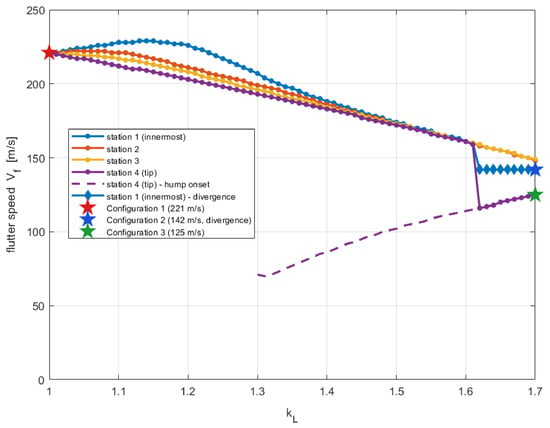
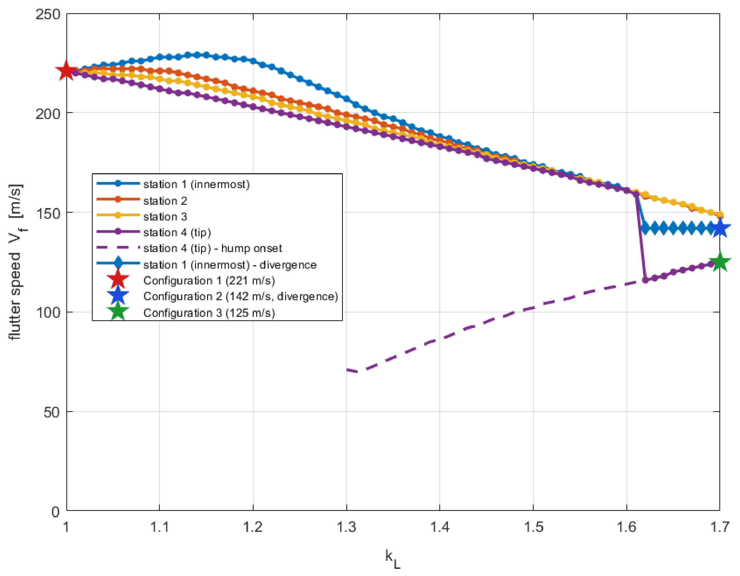
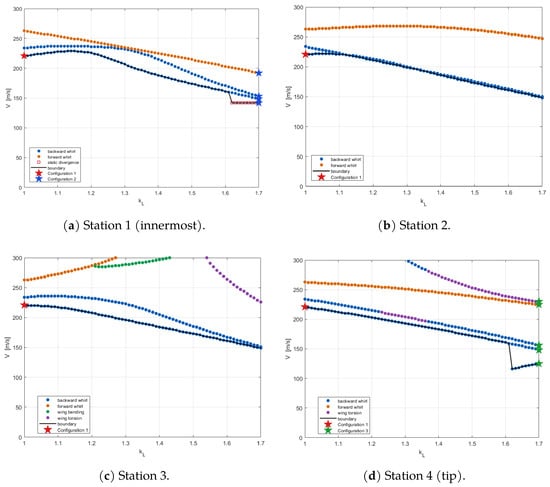
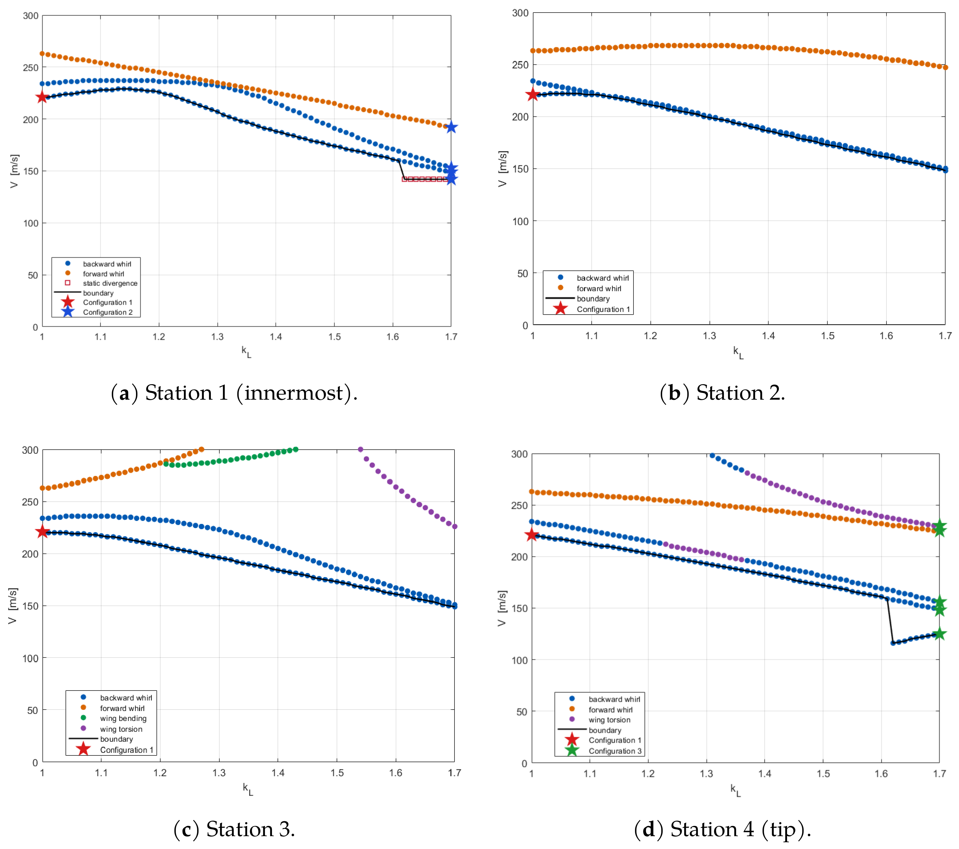
The governing boundaries obtained for all four stations are presented in Figure 17. The three configurations of the preceding sections have been marked on the same figures: Configuration 1 at , Configuration 2 at station 1, and Configuration 3 at station 4, the latter two both at .
Figure 17.
Stability boundary versus disk-area concentration for each spanwise station of the large unit.
When the curves are examined in detail, four features may be pointed out. Firstly, the boundary is not monotonic in the vicinity of . If the large unit is placed at the innermost station, the flutter speed is seen to rise from 221 m/s to 229 m/s at before it begins to fall, which corresponds to a gain of approximately 3.6%. A moderate degree of concentration, applied inboard, is therefore slightly beneficial. The gain itself is small and could not be relied upon as a design margin; its significance is rather that the loss of stability observed for Configurations 2 and 3 must be attributed to large concentration, and not to concentration as such.
Secondly, the four stations are seen to converge. The spread between the most and the least favorable placement amounts to 23 m/s at , is reduced to 5 m/s at , and becomes indistinguishable at , where all four stations yield 161 m/s. It may therefore be concluded that spanwise placement is most influential at moderate concentration and ceases to be influential once the concentration is sufficiently large, since by that stage, the large unit dominates the inertia irrespective of where it is installed.
Thirdly, the ordering of the stations at moderate is the expected one, the inboard placement being the most stable and the tip placement the least. The margin between them is nevertheless moderate, of the order of 10% at , and it is considerably smaller than the effect of concentration itself over the same interval. Between and , the governing speed is reduced by 33% to 43% depending on the station, whereas the station-to-station spread never exceeds 24 m/s.
Fourthly, new mechanisms that are specific to the individual stations appear above , and it is these which interrupt the otherwise smooth trend. At station 1, a static divergence at 142 m/s takes over the boundary from inwards so that this arrangement becomes divergence-critical instead of flutter-critical and its boundary is flattened. At station 4, on the other hand, a low-speed backward-whirl branch appears at in the form of a hump mode, which is drawn with a dashed line because it stabilizes again above the crossing. Its damping deepens smoothly from at the onset to at , and it becomes a persistent instability at . In the interval , the structural damping that would be required in order to suppress this branch lies between and , that is, within the range normally assumed for a metallic wing. However, this is not treated as a design boundary, since above , no such ambiguity remains, so the suppression of the branch at would demand . The underlying mechanism of this branch remains unresolved. Its frequency varies with airspeed as the rotational speed changes, and the observed hump may result from interaction with a wing mode or from variations in aerodynamic damping with reduced frequency. The present results do not allow these effects to be distinguished. Potential mitigation strategies include modifying the mount damping, adjusting its tuning, or changing the unit’s spanwise location; however, these options have not been investigated and remain subjects for future work.
As the overhang scales with the unit, the sweep changes two parameters simultaneously. Repeating the analysis at , while varying disk scaling and overhang independently, shows that enlarging the disks with fixed pylons raises the boundary by 31–33 m/s. Lengthening the enlarged unit’s pylon provides a further increase of 6–12 m/s, whereas shortening the other three pylons, as required by disk-area conservation, reduces the boundary by 25–33 m/s. The destabilization therefore arises not from disk-area concentration itself but from shortening the pylons of the units that relinquish disk area. Since these contributions are not strictly additive, the decomposition indicates their signs and approximate magnitudes.
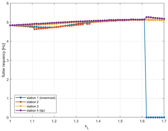
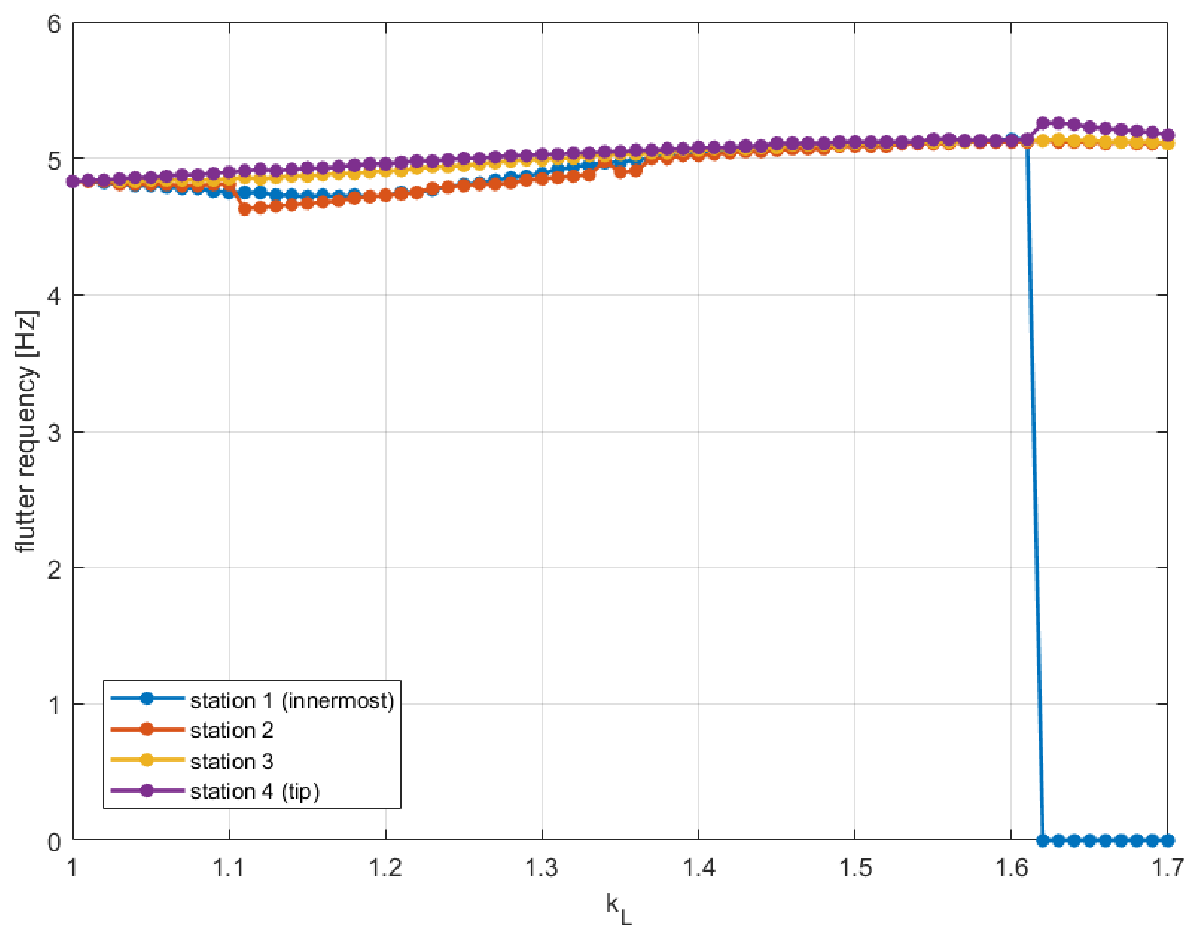
The frequency of the governing branch is given in Figure 18. Apart from the divergence band at station 1, where the frequency is zero by definition, it is seen to remain between 4.6 and 5.3 Hz over the entire sweep and for all four stations. The instability that sets the boundary is consequently the same backward-whirl mechanism throughout, and the effect of concentration must be regarded as quantitative: the speed at which this mode becomes unstable is lowered, but the mode itself is not replaced by a different one.
Figure 18.
Frequency of the branches against .
If Figure 19 is investigated, in which every unstable branch is plotted and colored according to the mode family assigned by the identification procedure of Section 3.3.1, it becomes apparent that the backward-whirl family sets the boundary everywhere. Forward whirl is present throughout, but always at a higher speed. The wing families enter only at the extremes of the range: wing torsion becomes unstable above at station 3 and above at station 4, in both cases as the coupling between the large unit and the torsion mode is strengthened.
Figure 19.
Unstable branches against for each spanwise station of the large unit.
Considered as a whole, the sweep permits a more specific statement to be made than the three individual configurations would allow. The concentration of installed disk area into a single large unit is the dominant effect, costing between one third and 43% of the flutter margin over the range examined, and it produces this loss without altering the underlying mechanism. Spanwise placement constitutes a secondary effect, whose influence is greatest at moderate concentration and vanishes at high concentration, but which nevertheless determines the behavior at the extremes. An inboard large unit reaches its limit through static divergence, whereas a tip-mounted one does so through a low-speed whirl mode appearing well below the nominal boundary. For a distributed-propulsion wing, these observations argue in favor of keeping the propellers as uniform as the installation permits and, where such asymmetry cannot be avoided, of examining divergence and hump modes explicitly instead of relying upon the lowest oscillatory crossing alone.
Taken together, these results support the following design guidance. Uniform propeller sizing is preferable where practical, although mild nonuniformity incurs little penalty; substantial stability loss, reaching roughly one-third or more, occurs only under strong size concentration. Spanwise placement matters primarily at intermediate concentration, where inboard placement is more favorable in the soft-mount regime considered here. At low concentration, placement has little effect, and at high concentration, all four stations give nearly the same boundary, so only the size ratio matters. A practical mitigation is to preserve the overhang of the smaller units, since the penalty arises from shortening their pylons and not from the larger disk itself. Critical modes should also be tracked by their physical characteristics, since their behavior can change with airspeed and their labels may no longer reflect the underlying instability.
These conclusions are subject to the limitations of the model and of the configurations examined. The study considers four propellers throughout; although the formulation applies to any number, the influence of propeller count remains to be investigated. The model assumes sectional aerodynamics, quasi-steady propeller derivatives, rigid blades, soft mounts, and no aerodynamic interference. Absolute stability boundaries are therefore less certain than relative comparisons between configurations evaluated under the same assumptions. The findings should be treated as qualitative guidance and not as definitive design limits; quantitative values for a specific aircraft require applying the same methodology with aircraft-specific data.
4. Conclusions
The whirl-flutter behavior of a flexible wing carrying four propellers has been investigated by varying the distribution of a fixed total propeller disk area. The aeroelastic system was solved using both frequency-domain p-k and time-domain Wagner formulations, with the two approaches agreeing well with each other.
For the three baseline layouts, the governing stability speed decreases from 221 m/s for four equal propellers to 142 m/s for an inboard enlarged propeller and 125 m/s for a tip-mounted enlarged propeller. The inboard configuration reaches its limit through static divergence, while the tip configuration exhibits a low-speed hump mode. A continuous parametric study shows that disk-area concentration is the dominant factor, reducing the stability margin by up to 43%, whereas spanwise placement has a secondary influence. Moderate inboard concentration can initially improve the flutter speed by approximately 3.6%, indicating that the observed degradation results primarily from strong size concentration rather than asymmetry alone.This gain is comparable in magnitude to the expected correction from aerodynamic interference and is therefore interpreted as evidence of non-monotonic behavior near the equal-propeller limit.
The instability mechanism remains a backward whirl throughout the parameter range, with frequencies between 4.6 and 5.3 Hz. Forward-whirl branches become unstable only after transitioning to wing-dominated modes, indicating that they do not govern the stability boundary within the configurations considered. These results suggest that relatively uniform propeller sizes are generally favorable for preliminary design, while divergence and hump modes should also be considered when assessing asymmetric configurations.
The conclusions are subject to three main limitations: blade flexibility, aerodynamic interference between propeller disks and the wing, and the fixed mount stiffness. Blade flexibility may provide additional stabilization, whereas aerodynamic interference can reduce the stability boundary. Because the same model is applied to all configurations, such a correction is expected to shift their boundaries consistently, preserving their relative ranking and concentration-related margins while potentially altering the absolute boundary values. The present configurations remain within the soft-mount regime; therefore, investigating higher mount stiffness, where wing flutter may become dominant, is a natural extension of the study.
Supplementary Materials
The following supporting information can be downloaded at: https://www.mdpi.com/article/10.3390/app162110631/s1, Figure S1: Continuous modal composition of the exchanging pair of Configuration 3; Figure S2: Continuous modal composition of Configuration 1 and Configuration 2; Table S1: Galerkin convergence study; Table S2: Galerkin convergence of the oscillatory stability boundaries.
Author Contributions
Conceptualization, S.E.; methodology, S.E. and A.E.; software, Y.E.D.; validation, Y.E.D. and A.E.; formal analysis, Y.E.D.; investigation, Y.E.D.; visualization, Y.E.D.; writing—original draft preparation, Y.E.D.; writing—review and editing, A.E. and S.E.; supervision, A.E. and S.E.; project administration, S.E.; funding acquisition, S.E. All authors have read and agreed to the published version of the manuscript.
Funding
This research was supported by the Scientific and Technological Research Council of Türkiye (TÜBİTAK), grant number 223M205.
Data Availability Statement
The data supporting the findings of this study are available from the corresponding author upon reasonable request.
Conflicts of Interest
The authors declare no conflicts of interest. The funders had no role in the design of the study; in the collection, analyses, or interpretation of data; in the writing of the manuscript; or in the decision to publish the results.
Appendix A. Assembled System Matrices for Np Propellers
Appendix A.1. Degrees of Freedom and Block Layout
The generalized coordinate vector places the pylon rotations first and the Galerkin coordinates of the wing last,
where the bending and torsion shape function rows and , each of size , are evaluated. All propeller properties carry the index p and may differ from one unit to the next.
The system matrix has the same layout: a block-diagonal pylon–pylon partition, one coupling block per propeller to the wing, and a single wing–wing partition to which all propellers contribute,
the sub-blocks being of size , , , and . The damping, stiffness, and the three aerodynamic matrices share this layout exactly and are given block by block below.
Appendix A.2. Propeller Structural Blocks
Appendix A.3. Propeller Aerodynamic Blocks
Writing four load-transfer combinations for the coefficient that appears in row r of propeller p owing to the input x, with the disk diameter and , , and the pivot offsets,
where The superscript names the equation the term lands in and the subscript names the motion that produces it, so , for example, is the wing torsion moment generated by the disk pitch rate of propeller p. The components of aerodynamic stiffness blocks are
The aerodynamic damping adds the rate derivatives, each pylon rotation contributing both an induced angle through its offset and a disk rate through the radius,
The rate derivatives acting on the rate of the induced angle arising from aerodynamic mass involves only the q and r terms,
None of the aerodynamic blocks is symmetric, and the wing–pylon partitions are not transposes of the pylon–wing partitions.
Appendix A.4. Wing Blocks
The wing contributions are common to every configuration,
The unsteady strip-theory operators , , and are assembled from the same quadrature, with the semichord , the elastic-axis offset a, and the Jones coefficients entering through the integrands given in Section 2.5.
Appendix A.5. Aerodynamic Lag States
Jones approximation to Wagner’s function adds two lag states per wing degree of freedom, coordinates , governed by
with , , and diagonal in the same partition with entries . The lag states belong to the wing alone, so their number does not depend on ; the propellers enter only through the width of the leading zero block in and its height in .
Appendix A.6. State-Space Form
With , , and , the first-order system in reads with
Table A1 lists the dimensions for the configurations of this study.
Table A1.
Matrix dimensions for Galerkin terms in each of bending and torsion.
The expansion uses five functions in bending and five in torsion to ensure convergence. A convergence study, provided as Supplementary Material, demonstrates that the computed boundaries remain stable with increasing discretization, with the reference boundary for the comparisons below remaining unchanged across the discretizations considered.
References
- European Commission; Directorate-General for Research and Innovation; Directorate-General for Mobility and Transport. Flightpath 2050—Europe’s Vision for Aviation—Maintaining Global Leadership and Serving Society’s Needs; Publications Office: Luxembourg, 2011. [Google Scholar]
- Airlines for Europe (A4E); ACI EUROPE; ASD; CANSO Europe; ERA. Destination 2050: A Route to Net Zero European Aviation; Report; Destination 2050: Brussels, Belgium, 2021. [Google Scholar]
- Reed, W.H., III. Propeller-Rotor Whirl Flutter: A State-of-the-Art Review. J. Sound Vib. 1966, 4, 526–544. [Google Scholar] [CrossRef] [Scilit]
- Reed, W.H., III. Review of Propeller-Rotor Whirl Flutter; NASA Technical Report NASA-TR-R-264; National Aeronautics and Space Administration, Langley Research Center, Langley Station: Hampton, VA, USA, 1967.
- Taylor, E.S.; Browne, K.A. Vibration Isolation of Aircraft Power Plants. J. Aeronaut. Sci. 1938, 6, 43–49. [Google Scholar] [CrossRef] [Scilit]
- Ribner, H.S. Propellers in Yaw; NACA Report NACA-TR-820; National Advisory Committee for Aeronautics: Washington, DC, USA, 1945. [Google Scholar]
- Reed, W.H., III; Bland, S.R. An Analytical Treatment of Aircraft Propeller Precession Instability; NASA Technical Note NASA-TN-D-659; National Aeronautics and Space Administration: Washington, DC, USA, 1961.
- Abbott, F.T., Jr.; Kelly, H.N.; Hampton, K.D. Investigation of Propeller-Power-Plant Autoprecession Boundaries for a Dynamic-Aeroelastic Model of a Four-Engine Turboprop Transport Airplane; NASA Technical Note NASA-TN-D-1806; National Aeronautics and Space Administration: Washington, DC, USA, 1963.
- Houbolt, J.; Reed, W. Propeller-nacelle whirl flutter. J. Aerosp. Sci. 1962, 29, 333–346. [Google Scholar] [CrossRef] [Scilit]
- Bennett, R.M.; Bland, S.R. Experimental and Analytical Investigation of Propeller Whirl Flutter of a Power Plant on a Flexible Wing; NASA Technical Note NASA-TN-D-2399; National Aeronautics and Space Administration: Washington, DC, USA, 1964.
- Sewall, J.L. An Analytical Trend Study of Propeller Whirl Instability; NASA Technical Note NASA-TN-D-996; National Aeronautics and Space Administration: Washington, DC, USA, 1962.
- Scanlan, R.H.; Truman, J.C. The Gyroscopic Effect of a Rigid Rotating Propeller on Engine and Wing Vibration Modes. J. Aeronaut. Sci. 1950, 17, 653–659, 666. [Google Scholar] [CrossRef] [Scilit]
- Koch, C. Parametric Whirl Flutter Study Using Different Modelling Approaches. CEAS Aeronaut. J. 2022, 13, 57–67. [Google Scholar] [CrossRef] [Scilit]
- Massey, S.J.; Wieseman, C.D.; Stanford, B.; Heeg, J. Aeroelastic Analysis of a Distributed Electric Propulsion Wing. In 58th AIAA/ASCE/AHS/ASC Structures, Structural Dynamics, and Materials Conference; AIAA SciTech Forum: Orlando, FL, USA, 2017. [Google Scholar][Green Version]
- Hoover, C.B.; Shen, J.; Kreshock, A.R.; Stanford, B.; Piatak, D.J.; Heeg, J. Whirl Flutter Stability and Its Influence on the Design of the Distributed Electric Propeller Aircraft X-57. In 17th AIAA Aviation Technology, Integration, and Operations Conference; AIAA Aviation Forum: Orlando, FL, USA, 2017. [Google Scholar][Green Version]
- Böhnisch, N.; Braun, C.; Koschel, S.; Marzocca, P. Whirl Flutter for Distributed Propulsion Systems on a Flexible Wing. In AIAA SCITECH 2022 Forum; AIAA Science and Technology Forum and Exposition: Orlando, FL, USA, 2022. [Google Scholar]
- Böhnisch, N.; Braun, C.; Muscarello, V.; Marzocca, P. About the Wing and Whirl Flutter of a Slender Wing–Propeller System. J. Aircr. 2024, 61, 1–14. [Google Scholar] [CrossRef] [Scilit]
- Böhnisch, N.; Braun, C.; Marzocca, P.; Muscarello, V. Impact of Aerodynamic Interactions on Aeroelastic Stability of Wing-Propeller Systems. Appl. Sci. 2024, 14, 8709. [Google Scholar] [CrossRef] [Scilit]
- Koch, C.; Koert, B. Including Blade Elasticity into Frequency-Domain Propeller Whirl Flutter Analysis. J. Aircr. 2024, 61, 774–784. [Google Scholar] [CrossRef] [Scilit]
- Böhnisch, N.; Braun, C.; Marzocca, P.; Muscarello, V. Insights into the Aeroelastic Stability of a Wing with Distributed Electric Propulsion Systems. Aerosp. Sci. Technol. 2026, 168, 110763. [Google Scholar] [CrossRef] [Scilit]
- Wang, Z.; Xu, V.; Breuker, R.D. Preliminary aeroelastic design of composite wings with distributed electric propulsion. In Proceedings of the 19th International Forum on Aeroelasticity and Structural Dynamics (IFASD 2022), Madrid, Spain, 13–17 June 2022; Volume 1, pp. 561–575. [Google Scholar]
- Wang, Z.; Liu Xu, V.Q.; De Breuker, R. Preliminary aeroelastic optimization of electric aircraft wings including propeller whirl flutter effects. Aerosp. Sci. Technol. 2025, 157, 109813. [Google Scholar] [CrossRef] [Scilit]
- Rose, T.; Rodden, W.P. Propeller/nacelle whirl flutter addition to MSC/NASTRAN. In Proceedings of the 1989 MSC World User’s Conference, Los Angeles, CA, USA, 15–17 March 1989. [Google Scholar]
- Cecrdle, J. Whirl Flutter of Turboprop Aircraft Structures; Elsevier: Amsterdam, The Netherlands, 2015. [Google Scholar]
- Xu, V.Q.L. Propeller-Wing Whirl Flutter: An Analytical Study. Master’s Thesis, TUDelft University, Delft, The Netherlands, 2020. [Google Scholar]
- Bielawa, R.L. Rotary Wing Structural Dynamics and Aeroelasticity, 2nd ed.; AIAA: Reston, VA, USA, 2006. [Google Scholar]
- Theodorsen, T. General Theory of Aerodynamic Instability and the Mechanism of Flutter; NACA-TR-496; NASA: Washington, DC, USA, 1949.
- Jones, R.T. Operational Treatment of the Nonuniform Lift Theory to Airplane Dynamics; Technical Note NACA-TN-667; National Advisory Committee for Aeronautics: Washington, DC, USA, 1938. [Google Scholar]
- Wagner, H. Über die Entstehung des dynamischen Auftriebes von Tragflügeln (On the Origin of Dynamic Lift of Airfoils). ZAMM (J. Appl. Math. Mech.) 1925, 5, 17–35. [Google Scholar]
- Rodden, W.P.; Harder, R.L.; Bellinger, E.D. Aeroelastic Addition to NASTRAN; Technical Report NASA CR-3094; NASA Langley Research Center: Washington, DC, USA, 1979.
- Allemang, R.J.; Brown, D.L. A Correlation Coefficient for Modal Vector Analysis. In Proceedings of the 1st International Modal Analysis Conference, Orlando, FL, USA, 8–10 November 1982; pp. 110–116. [Google Scholar]
- Allemang, R.J. The Modal Assurance Criterion–Twenty Years of Use and Abuse. J. Sound Vib. 2003, 37, 14–21. [Google Scholar]
- MSC Software. MSC Nastran Dynamic Analysis User’s Guide; MSC Software: Irvine, CA, USA, 2022. [Google Scholar]
- Bisplinghoff, R.L.; Ashley, H.; Halfman, R.L. Aeroelasticity; Dover Publications: New York, NY, USA, 1996. [Google Scholar]
- Bismarck-Nasr, M.N. Coalescence of Aeroelastic Modes in Flutter Analysis. J. Aircr. 1992, 29, 505–507. [Google Scholar] [CrossRef] [Scilit]
- Ewins, D.J. Modal Testing: Theory, Practice and Application, 2nd ed.; Wiley: Hoboken, NJ, USA, 2000. [Google Scholar]
- Meirovitch, L. Principles and Techniques of Vibrations; Prentice Hall: Hoboken, NJ, USA, 1997. [Google Scholar]
- Bland, S.R.; Bennett, R. Wind-Tunnel Measurement of Propeller Whirl-Flutter Speeds and Static-Stability Derivatives and Comparison with Theory; Technical Note D-1807; NASA: Washington, DC, USA, 1963.
- Doğru, Y.E.; Eken, A.; Eken, S. Comparative Aeroelastic Analysis of Distributed Electric Propulsion Wings. In Proceedings of the International Forum on Aeroelasticity and Structural Dynamics (IFASD), Goettingen, Germany, 17–21 June 2026. [Google Scholar]
- Perkins, N.C.; Mote, C.D. Comments of Curve Veering and Mode Localization. J. Sound Vib. 1986, 106, 451–463. [Google Scholar]

Disclaimer/Publisher’s Note: The statements, opinions and data contained in all publications are solely those of the individual author(s) and contributor(s) and not of MDPI and/or the editor(s). MDPI and/or the editor(s) disclaim responsibility for any injury to people or property resulting from any ideas, methods, instructions or products referred to in the content. |
© 2026 by the authors. Licensee MDPI, Basel, Switzerland. This article is an open access article distributed under the terms and conditions of the Creative Commons Attribution (CC BY) license.