


Abstract
Beam–column joints (BCJs) are widely recognized as critical structural components that govern the seismic performance of reinforced concrete (RC) frame structures. Their measurements captured changes associated with susceptibility to brittle joint shear failure under cyclic loading, which often results in rapid strength degradation, limited energy dissipation, and reduced structural resilience. Although various retrofitting techniques have been developed to enhance the seismic behavior of deficient BCJs, continuous assessment of their structural condition remains essential for ensuring their long-term reliability. This study experimentally investigates the seismic performance and structural health monitoring (SHM) of RC BCJs retrofitted using a hybrid strengthening scheme comprising Near-surface-mounted (NSM) carbon fiber reinforced polymer (C-FRP) ropes and externally bonded C-FRP sheets. Two full-scale exterior BCJ subassemblages were subjected to quasi-static cyclic loading. Their structural response was evaluated in terms of hysteretic behavior, load-carrying capacity, stiffness degradation, energy dissipation, and joint shear deformation. In parallel, the applicability of the electromechanical impedance (EMI)-based SHM technique was investigated using externally bonded piezoelectric lead zirconate titanate (PZT) transducers. The experimental results showed that, compared with the reference specimen, the retrofitted specimen exhibited a 17.9% higher positive peak lateral load and a 54.0% higher total cumulative dissipated energy, together with reduced joint shear deformation and delayed strength degradation. Rupture of the externally bonded C-FRP sheet occurred at 3% story drift (sixth loading step). Furthermore, the EMI measurements captured progressive changes in the monitored structural condition during cyclic loading, while also highlighting the influence of sensor location and sensor–structure coupling on damage detection, particularly after rupture of the externally bonded C-FRP sheets.
1. Introduction
A substantial proportion of the existing reinforced concrete (RC) building stock remains highly vulnerable to earthquake-induced damage, notably in regions of moderate-to-high seismicity. This vulnerability is mainly attributed to the inadequate seismic detailing and limited ductility requirements prescribed by earlier generations of seismic design codes [1]. Following the calamitous results of the 1994 Northridge and 1995 Kobe earthquakes, considerable advances were made in seismic design concepts, leading to substantially enhanced ductility and capacity design requirements in modern seismic codes [2]. Despite these improvements, many existing RC structures were designed and constructed before the implementation of these provisions and therefore continue to manifest significant seismic deficiencies. Among the various structural components, reinforced concrete beam–column joints (BCJs) have consistently been identified as among the most critical components governing the seismic performance of RC frame structures [3]. Experimental investigations and post-earthquake reconnaissance studies have demonstrated that non-ductile BCJs frequently exhibit brittle shear failures under cyclic loading, resulting in rapid strength degradation and limited energy dissipation capacity [4,5]. Such deficiencies have been repeatedly associated with extensive structural damage and, in numerous cases, partial or complete collapse of RC buildings during major seismic events worldwide [6]. Therefore, enhancing the shear capacity of BCJs in existing RC structures through appropriate seismic strengthening methods, along with continuous monitoring of their structural performance, is crucial for mitigating the risk of collapse during significant earthquakes, especially in structures with inadequate seismic resilience [7].
In response to the seismic deficiencies in existing RC structures, retrofitting has emerged as an effective and widely adopted strategy to enhance structural resilience to earthquake loading [8]. As a result, extensive research has been devoted to the seismic strengthening of RC BCJs, leading to the development and validation of various retrofit techniques in recent decades. The most extensively studied methods include RC jacketing [9,10,11], steel jacketing or steel hoop confinement [12,13], fiber-reinforced polymer (FRP) wrapping [14,15,16,17,18], fiber-reinforced cementitious matrix (FRCM) [19,20], and hybrid strengthening systems [21,22]. These approaches have consistently demonstrated the ability to improve the shear strength, ductility, stiffness, and energy-dissipation capacity of BCJs subjected to cyclic seismic loading.
Among the available retrofit strategies, FRP composites have become one of the most widely adopted solutions for the seismic upgrading of existing RC structures. Their widespread use is primarily attributed to several inherent advantages, including their high strength-to-weight ratio, excellent corrosion resistance, ease of installation, and, most importantly, the minimally invasive nature of the intervention, which significantly reduces construction time and disruption to building occupancy [23]. Consequently, FRP systems have attracted considerable research interest in the repair and strengthening of RC structural members subjected to seismic loading. Numerous experimental and analytical studies have demonstrated the effectiveness of FRP composites in enhancing the strength, stiffness, ductility, and energy dissipation capacity of RC beams [24,25,26], columns [27,28], and BCJs [29]. Despite their proven effectiveness, several challenges remain, with premature debonding at the FRP–concrete interface being one of the most critical failure mechanisms that limit the full utilization of FRP materials [30,31].
Externally bonded FRP sheets [32,33] are among the most widely used retrofitting schemes for RC BCJs due to their ease of application, rapid installation, and minimal disruption to the existing structure. However, their effectiveness is often limited by anchorage deficiencies and premature debonding, particularly in open-jacket configurations subjected to cyclic loading. To overcome these limitations, the NSM technique using FRP [34] has been extensively investigated, offering improved anchorage conditions and enhanced durability. More recently, carbon fiber reinforced polymer (C-FRP) ropes have emerged as a promising NSM strengthening solution for RC structural members, demonstrating remarkable performance under seismic loading. In particular, the use of C-FRP ropes in shear-deficient RC BCJs has shown considerable potential to mitigate premature debonding, a primary shortcoming of externally bonded FRP systems, by forming closed stirrup-like reinforcement. Sapidis et al. [6] experimentally investigated the use of C-FRP ropes to form NSM closed incline hoops in the joint core and demonstrated a substantial enhancement of the seismic performance of deficient RC beam–column joints. Although the proposed technique effectively restrained the development of shear cracks within the joint core and significantly enhanced its seismic capacity, it could not alter the governing failure mechanism. Failure remained governed by brittle joint shear rather than the desirable flexural yielding of the beam accompanied by plastic hinge formation.
The structural performance of retrofitted RC members is inherently complex owing to the interaction between the existing concrete substrate and the externally applied strengthening materials. Thus, the development of robust structural health monitoring (SHM) techniques to monitor the performance of the retrofitted members is of utmost importance [35]. Recent advancements in SHM technologies have led to significant growth in their applications, particularly in damage detection and localization of conventional and retrofitted RC members [36]. The electromechanical impedance (EMI) method represents a promising advancement among the emerging techniques in SHM due to its high sensitivity to local damage. The EMI method, or equivalently the electromechanical admittance, utilizes the piezoelectric effect of smart materials, such as lead zirconate titanate (PZT) patches, to monitor the structural condition of the monitored member. The resulting SHM scheme offers several advantageous attributes, including ease of implementation, cost-effectiveness, portability, low energy consumption, and a compact design [37,38]. Over the years, a substantial body of literature has emerged on the implementation of the EMI method for the prompt detection of damage related to concrete cracking under static or varying stress fields [39,40,41,42,43,44,45,46], rebar corrosion [47,48,49,50], and yielding [51]. Furthermore, the efficacy of the EMI method for SHM of RC and fiber-reinforced concrete beams under bending loading [52,53,54] has been investigated. Moreover, researchers have conducted experimental investigations into the applicability of the EMI method in full-scale members of RC structures, including beams [55,56,57,58,59] and joints [6,60,61,62,63,64]. More broadly, recent developments in sensor-based SHM have increasingly incorporated data-driven approaches to interpret monitoring signals. Machine learning methods can support the transformation of complex sensor data into engineering information for tasks such as damage detection, localization, and severity assessment, although challenges related to limited labeled damage data, environmental and operational variability, interpretability, and transferability remain [65]. While many studies have independently explored the seismic retrofitting of RC BCJs and the application of EMI-based SHM techniques to RC structures, a notable gap remains in the literature on the continuous SHM of retrofitted BCJs enhanced with innovative C-FRP schemes.
This study presents an experimental investigation on the seismic retrofitting and SHM of two full-scale exterior RC beam–column joints. Although the investigation shares a similar general experimental framework with the authors’ previous study [6], it is based on different specimens and independent experimental and EMI datasets. Specifically, a distinct hybrid strengthening scheme consisting of NSM C-FRP ropes and externally bonded C-FRP sheets is evaluated under quasi-static cyclic loading. Furthermore, in contrast to the discrete EMI measurements employed in ref. [6], the present study implements continuous acquisition of PZT-based EMI measurements during loading over a narrower frequency range, allowing the evolution of the EMI response to be tracked throughout the loading history. The response of the strengthening system and the EMI technique is assessed through structural response parameters and damage-sensitive EMI signatures, providing an experimental demonstration of the combined application of seismic retrofitting and continuous condition monitoring in the tested RC BCJs.
2. Materials and Methods
2.1. Specimens Characteristics and Strengthening Scheme Details
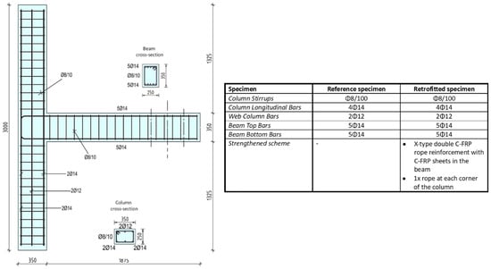
This investigation entailed casting two similar full-scale RC BCJ subassemblages, analogous to those found in typical RC multi-storey frame dwellings. Accordingly, the beam had a cross-section of 250 × 350 mm, whereas the column had a cross-section of 350 × 250 mm, with total lengths of 1875 mm and 3000 mm, respectively. The columns of the tested specimens were longitudinally reinforced with four Ø14 mm bars placed at the corners of the column’s cross-section, and two Ø12 mm bars positioned at the midpoints of the corresponding sides. Additionally, the transverse reinforcement of both columns and beams consisted of closed Ø8 mm stirrups spaced at 100 mm intervals, whereas no stirrups were intentionally installed within the BCJ body. The reinforcement details and the geometric characteristics of the specimens are provided in Figure 1.
Figure 1.
Specimens’ characteristics and steel reinforcement detailing.
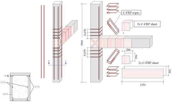
As previously mentioned, a hybrid strengthening scheme was employed to retrofit one of the specimens, hereafter referred to as the retrofitted specimen, while the other was designated as the reference specimen. The strengthening strategy incorporated NSM C-FRP ropes within the column and joint regions, as well as externally bonded C-FRP sheets in the joint and in the beam area proximal to the joint, as illustrated in Figure 2.
Figure 2.
Details of the strengthening scheme used in the investigation.
The first stage of the strengthening intervention involved installing C-FRP ropes using the NSM technique. Four C-FRP ropes were installed longitudinally along the columns, one at each corner, acting as additional longitudinal reinforcement. In addition, three closed C-FRP rope stirrups were installed in the critical region of each column to provide additional confinement and transverse resistance. Within the joint core, two C-FRP ropes were arranged diagonally on opposite faces, forming an X-shaped configuration for the shear strengthening of the joint. The diagonal ropes were configured as closed loops, providing continuity of the strengthening system around the joint region. This arrangement was intended to provide additional diagonal tensile resistance across the joint panel, thereby enhancing its resistance to joint shear stresses induced during cyclic loading.
The C-FRP ropes used in the present investigation were SikaWrap® FX-50C (SIKA Hellas, Kryoneri, Greece), consisting of unidirectional carbon fibers with a cross-sectional area greater than 28 mm2. Before installation, the dry C-FRP ropes were impregnated with the low-viscosity Sikadur®-52 (SIKA Hellas, Kryoneri, Greece) epoxy resin. Guiding lines were first marked on the concrete surface to define the position of the NSM grooves, which had nominal cross-sectional dimensions of 20 × 20 mm. The grooves were thoroughly cleaned using compressed air to remove dust and loose particles, and their outer edges were rounded with a minimum radius of 20 mm to reduce local stress concentrations. Particular care was taken during groove preparation to avoid damaging the existing longitudinal and transverse steel reinforcement. Following impregnation, the C-FRP ropes were positioned along the predefined strengthening paths. The longitudinal column ropes were anchored at their ends into drilled holes using Sika AnchorFix®-3+ (SIKA Hellas, Kryoneri, Greece), whereas the diagonal X-shaped ropes in the joint region formed closed strengthening loops.
The second stage of the retrofit involved the application of externally bonded S&P C-Sheet 240 C-FRP sheets in the beam region adjacent to the joint. The sheets consisted of unidirectional carbon fibers and had a nominal thickness of 0.168 mm per layer. Two layers of C-FRP sheets were applied with their fibers oriented parallel to the longitudinal axis of the beam, extending from the joint region over a length of 1550 mm along the beam. The longitudinally oriented sheets had a width of 300 mm. To improve their anchorage, three pairs of additional C-FRP sheets were applied transversely to the beam, with their fibers oriented perpendicular to the beam’s longitudinal axis. The transverse anchorage sheets had dimensions of 300 × 350 mm, with the 350 mm dimension oriented transversely to the longitudinal axis of the beam, as shown in Figure 2. The C-FRP sheets were bonded to the prepared concrete surface using S&P Resin 55 HP (S&P, Bad Nauheim, Germany) epoxy adhesive paste.
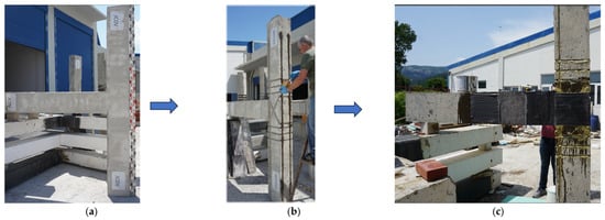
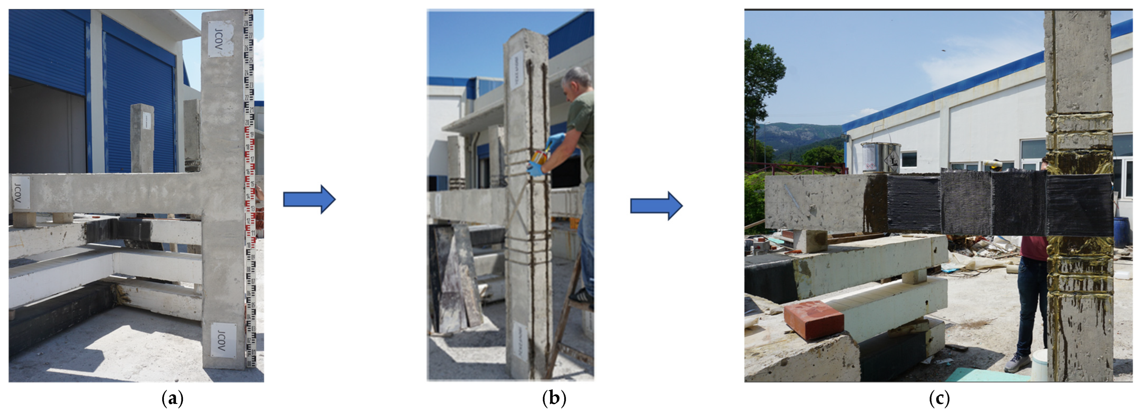
The hybrid strengthening configuration was conceived to address the principal deficiencies and expected damage mechanisms of the tested joint subassembly. The longitudinal C-FRP ropes and closed rope stirrups in the column regions were intended to supplement the existing longitudinal and transverse reinforcement and to improve confinement and resistance in the critical column regions. The X-shaped C-FRP ropes crossing the joint core were introduced to provide additional diagonal tensile resistance and enhance the shear response of the joint panel. The externally bonded C-FRP sheets in the beam region adjacent to the joint were intended to increase the local tensile resistance and control damage development in this critical region, while the transversely oriented sheets provided anchorage for the longitudinally oriented sheets. Thus, the rope and sheet components were used as complementary elements of a single retrofit strategy intended to delay premature joint deterioration and allow the subassembly to sustain larger deformation demands. The strengthening materials and their corresponding mechanical properties are discussed in Section 2.2. The application sequence of the retrofit, from the initial specimen to the installation of the NSM C-FRP ropes and the subsequent application of the externally bonded C-FRP sheets, is illustrated in Figure 3.
Figure 3.
Strengthening procedure of the BCJ specimen. (a) Initial specimen without strengthening intervention. (b) Application of the C-FRP ropes as NSM technique. (c) Application of externally bonded C-FRP sheets to the beam region adjacent to the joint.
2.2. Material Properties
The specimens were fabricated from the same batch of ready-mixed concrete; consequently, no construction joint was integrated. To evaluate the concrete compressive strength, uniaxial compression tests were conducted on six standard cylindrical specimens measuring 150 × 300 mm at 28 days after casting, while the full-scale BCJ specimens were tested after 28 days from casting. The tests yielded a mean cylindrical compressive strength of 34.35 MPa, with a standard deviation of 4.08 MPa, and individual values ranging from 25.5 to 37.2 MPa. The concrete was classified as C25/30, while a mean concrete compressive strength of MPa was adopted for the calculation of the column axial load. Furthermore, both tested specimens incorporated B500C-grade reinforcing steel, characterized by a yield strength of fy = 550 MPa, for the longitudinal and transverse rebars. Furthermore, the proposed strengthening scheme consisted of two primary components: C-FRP ropes and C-FRP sheets, which are commercially available under the trade names SikaWrap® FX-50C and S&P C-Sheet 240, respectively. The mechanical properties of the C-FRP components are presented in Table 1. The reported mechanical and physical properties of the reinforcing steel, C-FRP components, epoxy resins, and PZT transducers were obtained from the corresponding manufacturers’ technical datasheets.
Table 1.
Mechanical properties of the C-FRP component.
The C-FRP components were employed in conjunction with epoxy-based adhesives for impregnation, bonding, and anchorage. Sikadur®-52 low-viscosity epoxy resin was used to impregnate the dry ropes before installation on the specimen, while Sika AnchorFix®-3+ was used to anchor the synthetic ropes to the substrate of the specimen to achieve the proper transmission of the load between the strengthening scheme and the RC member. Similarly, S&P Resin 55 HP epoxy adhesive paste was used to secure the C-FRP sheets to the concrete surface within the beam’s plastic hinge region. The mechanical properties of the epoxy resins used in this investigation are presented in Table 2.
Table 2.
Mechanical properties of the epoxy resins.
Furthermore, piezoelectric transducers were used for EMI-based SHM in this research. Specifically, PZT patches designated PIC 151, commercially distributed by Pi Ceramics, were utilized. The density of the PZTs was 7800 kg/m3, their Poisson’s ratio was 0.34, their mechanical quality factor was 100, their dielectric loss factor was 20 × 10−3, and their relative permittivity was 2400 and 1980 in the parallel and perpendicular orientations relative to the polarity, respectively. Also, their dimensions were 2 cm × 2 cm × 0.5 cm.
2.3. Test Setup and Loading Sequence
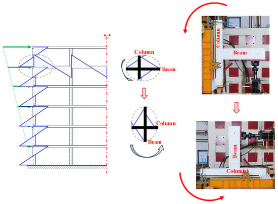
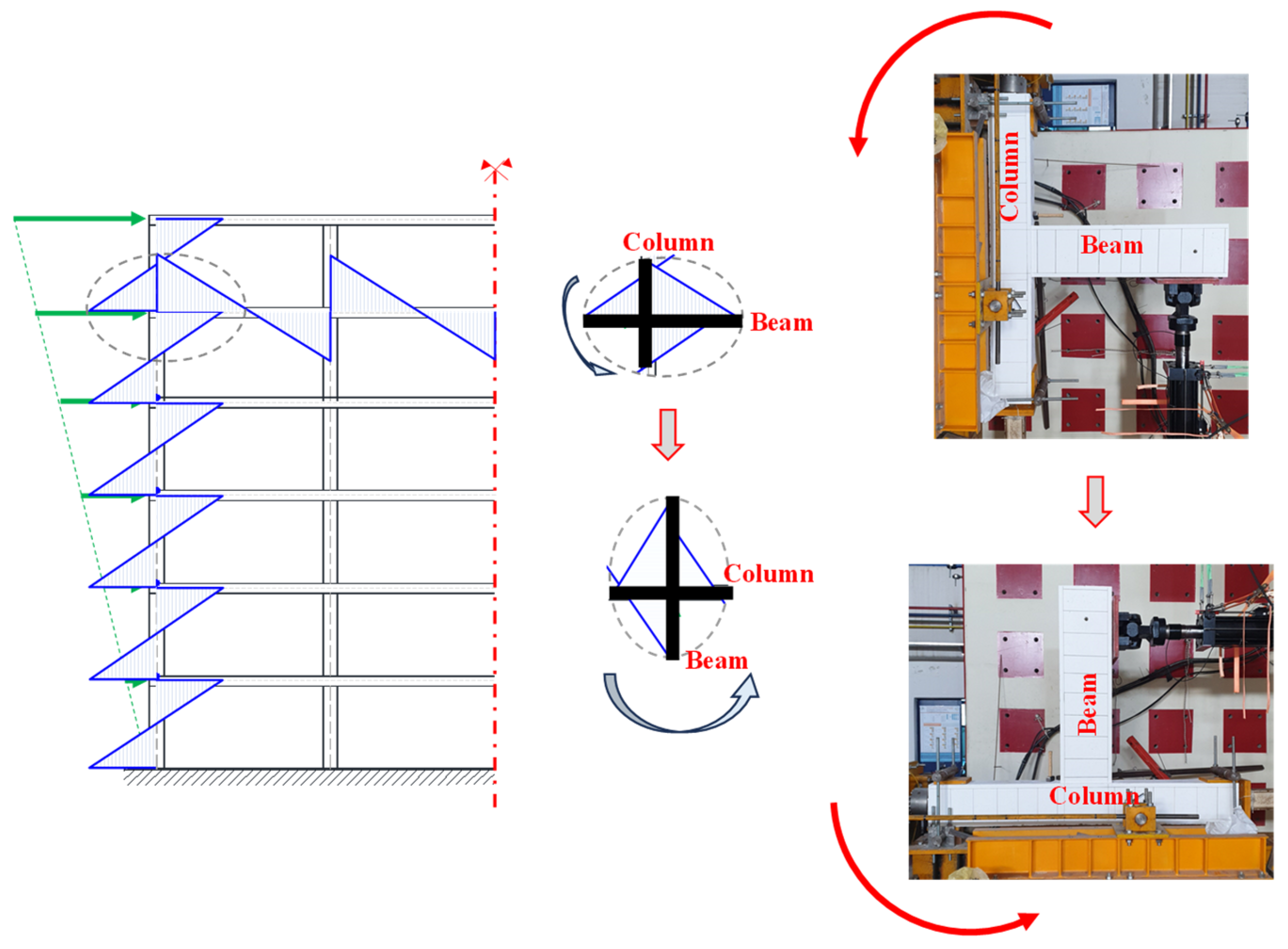
As previously noted, the experimental program consisted of two full-scale exterior BCJs constructed to simulate a segment of a typical RC frame multi-story structure, as depicted in Figure 4. The support conditions and loading configuration were selected to emulate the force transfer and restraint characteristics of an exterior joint within a conventional RC frame subjected to seismic excitation. The specimens were isolated at the assumed points of contraflexure of the beam and columns. Accordingly, the column ends were connected to the strong floor through pinned supports, implemented using sandwich-type steel plate mechanisms, which restrained translational movement while allowing rotation. Prior to installation in the experimental setup, each specimen was rotated by 90°, such that the column was positioned horizontally and the beam vertically. The cyclic lateral displacement was subsequently imposed at the beam end by the servo-controlled hydraulic actuator.
Figure 4.
Simulation of the seismic loading applied to the test specimens.
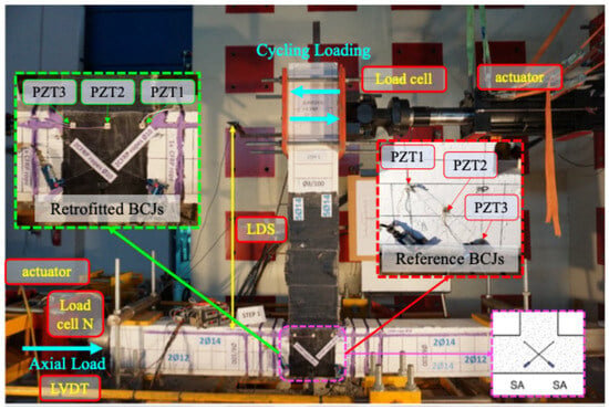
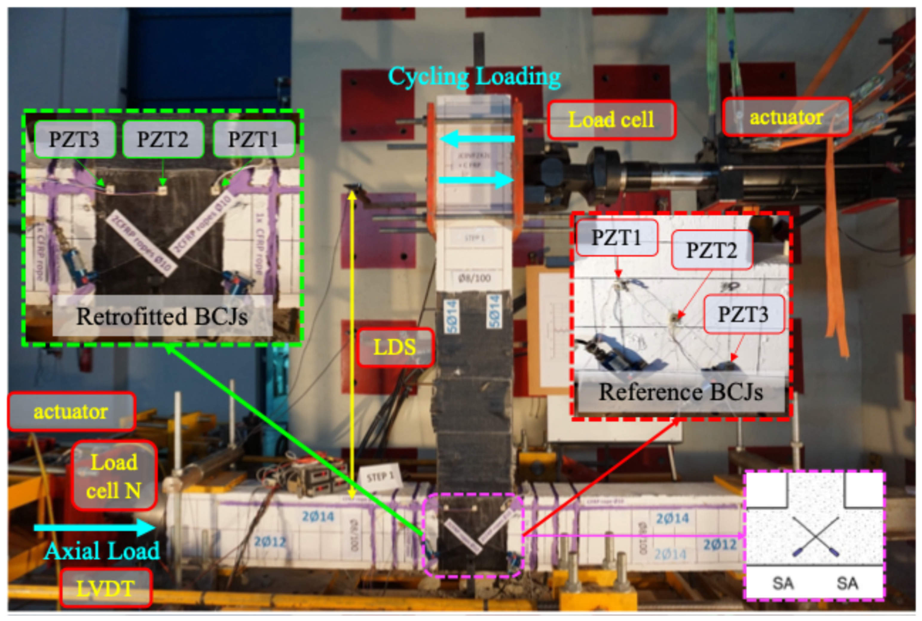
A double-acting, servo-controlled hydraulic actuator (MTS DuraGlide 241.41), with a maximum load capacity of 500 kN and a total stroke of 500 mm, was employed to impose the cyclic loading sequence on the free end of the beam, as illustrated in Figure 5. The actuator was equipped with an integrated high-precision linear variable differential transformer (LVDT) for continuous measurement of the imposed displacement. A constant axial compressive load , corresponding to a normalized axial-load ratio n of 5%, was applied to the column and maintained throughout the entire cyclic loading procedure, as defined in Equation (1). Considering the gross cross-sectional area of the column = 87,500 mm2 and the adopted concrete compressive strength = 34 MPa, the corresponding axial compressive force was = 148.75 kN.
where is the applied axial compressive force, is the gross cross-sectional area of the column, and is the concrete compressive strength adopted for the axial-load calculation. Furthermore, an independent external LVDT, with an accuracy of 0.01 mm and a total travel of 5 mm, was installed to monitor any unintended horizontal displacement of the column during testing. Two laser displacement sensors (LDSs) were also installed to monitor the beam displacement at different locations; however, only the measurements obtained from the LDS relevant to the present investigation were used in the subsequent analysis. The data acquisition frequency was set to 1 Hz for the first four loading steps and was subsequently increased to 2 Hz for the final four loading steps. Also, two string potentiometers were diagonally installed across the joint panel to determine its shear deformation. The sensors recorded the elongation and shortening of the two diagonals during cyclic loading. Following the procedure described in [66], and assuming approximately equal initial diagonal lengths and inclination angles, the average joint shear deformation, , was calculated according to Equation (2):
where and are the measured changes in length of the two diagonals, is their initial length, and is their initial inclination angle with respect to the horizontal axis. The diagonal arrangement of the string potentiometers is illustrated in Figure 5. The initial gauge length of each diagonal measurement line was approximately mm, with an inclination angle of approximately . Additionally, three WiAMS devices were utilized to record the EMI responses of the PZT transducer.
Figure 5.
Experimental setup and instrumentation.
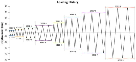
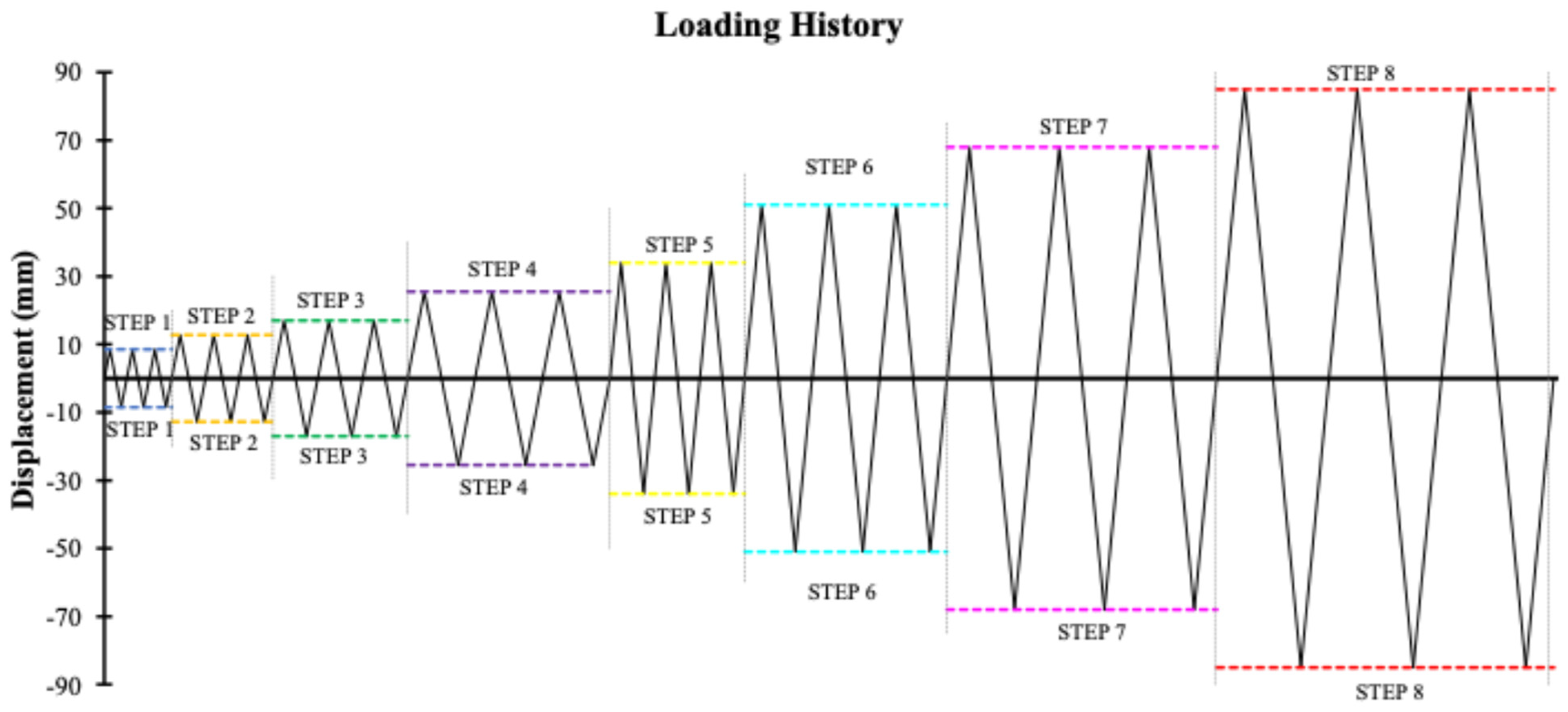
The two exterior BCJ specimens were subjected to the same quasi-static cyclic loading sequence. The loading protocol consisted of eight incremental displacement-controlled loading steps, corresponding to story drift ratios ranging from 0.5% to 5.0%, with each step comprising three complete loading cycles. The adopted quasi-static cyclic loading protocol was based on the experimental procedure previously employed in [67]. For each loading stage, the story drift ratio was determined from the measured beam-end displacement using a reference length of 1.70 m, defined as the distance from the point of load application to the column centerline. Accordingly, the imposed displacement amplitudes were ±8.50 mm, ±12.75 mm, ±17.00 mm, ±25.50 mm, ±34.00 mm, ±51.00 mm, ±68.00 mm, and ±85.00 mm, as illustrated in Figure 6 and summarized in Table 3. The displacement amplitudes were applied symmetrically in both loading directions with progressively increasing magnitude to simulate seismic loading conditions, as illustrated in Figure 4. This loading protocol was adopted to reproduce the hysteretic response of RC BCJs under earthquake actions and to evaluate their stiffness degradation, damage progression, and energy dissipation capacity.
Figure 6.
Quasi-static seismic loading sequence.
Table 3.
Quasi-static seismic loading protocol.
2.4. Implemented EMI-Based SHM Framework
This research employs the EMI method for the continuous SHM of BCJs subassemblies. The EMI method exploits the direct and inverse piezoelectric effects of PZTs to couple the electrical impedance of an attached PZT transducer to the mechanical impedance of the surrounding monitored host structure. According to Bhalla et al., the EMI response of PZTs under harmonic excitation is influenced by material constants and the mechanical impedance of the surrounding monitored host structure [51]. Therefore, any potential degradation of the structural integrity of the specimen results in modifications to the EMI response of the PZT. Thus, the proposed SHM scheme is based on continuously capturing the EMI response of externally bonded PZTs within a specified excitation frequency range to detect any potential degradation. The same PZT-based monitoring methodology was employed for both specimens, although different sensor-mounting configurations were adopted depending on the monitored substrate. In the reference specimen, the PZT sensors were epoxy-bonded directly to the concrete surface. In the retrofitted specimen, the PZT sensors were epoxy-bonded to the externally applied C-FRP sheets, thereby positioning the transducers directly on the strengthening system and in the vicinity of the anticipated critical region. This configuration was selected because structural health monitoring of the retrofitted specimen involves a multi-material system comprising the concrete substrate, the externally bonded C-FRP reinforcement, the adhesive layer, and their interfaces, in which different and potentially interacting damage mechanisms may develop during loading. Similar surface-bonded PZT configurations have previously been employed for impedance-based monitoring of C-FRP-retrofitted concrete members [68,69].
Additionally, the SHM scheme comprised three custom-made, miniature impedance analyzers to continuously capture the PZT sensors’ EMI responses throughout the loading sequence. The miniature impedance analyzers, called WiAMS (from “Wireless Impedance/Admittance Monitoring System”), have been introduced by Providakis et al. and used in many existing studies in the broader literature [70]. Three WiAMS devices were used to simultaneously acquire the responses of the three PZT transducers and automatically archive the measurements in an online database. The PZTs were harmonically excited using an excitation voltage of 2500 mV. For the reference specimen, each EMI sweep covered the frequency range 90–110 kHz with a 1 kHz increment, yielding 21 excitation frequency points. For the retrofitted specimen, each sweep covered the frequency range 80–115 kHz with a 1 kHz increment, yielding 36 excitation frequency points. These frequency ranges were selected to encompass the dominant resonance regions of the corresponding PZT responses.
The WiAMS measurement principle is based on the relationship between the PZT transducer’s electrical impedance magnitude and the peak voltage across it under harmonic excitation. For a fixed excitation voltage and measurement-circuit resistance, the measured peak voltage, , is directly dependent on the PZT impedance magnitude, . Consequently, variations in the acquired voltage-frequency response reflect corresponding variations in the electromechanical response of the coupled PZT–structure system. Accordingly, the experimentally acquired EMI signatures presented in this study are expressed in terms of the measured peak-voltage response (mV).
Prior to commencing the loading procedure, multiple consecutive EMI signatures were recorded for each PZT while the corresponding specimen remained in its healthy condition. These measurements collectively constituted the healthy baseline dataset. Subsequently, EMI responses were continuously acquired through consecutive frequency sweeps throughout the entire loading procedure. Therefore, the number of EMI signatures acquired during each loading step was not predefined but depended on the duration of that step. All measurements were conducted under stable indoor laboratory conditions. The acquired EMI signatures were processed without digital filtering or smoothing, and no outlier detection or removal procedure was applied.
Previous research has indicated that statistical damage indices are frequently utilized in EMI-based SHM to quantify alterations in impedance signatures caused by changes in the mechanical properties of the monitored structure. Among these, the root mean square deviation (RMSD) is one of the commonly employed statistical indices in EMI-based SHM to quantify deviations between baseline and subsequent electromechanical responses [39,51,71]. In the present study, the RMSD analysis was performed directly on the peak-voltage responses acquired by the WiAMS devices. For each EMI signature acquired during loading, the RMSD was independently calculated with respect to each signature of the healthy baseline dataset as follows:
where denotes the measured peak-voltage response at the excitation frequency of the EMI sweep acquired during loading, denotes the corresponding response of the healthy baseline sweep, and represents the total number of excitation frequency points.
For each acquired EMI signature, the RMSD values resulting from its comparison with all healthy baseline signatures were subsequently averaged to obtain a representative RMSD value:
where denotes the total number of EMI signatures contained in the healthy baseline dataset. Thus, each reported RMSD value represents the mean deviation of a given EMI signature from the complete set of healthy baseline measurements rather than from a single baseline signature. Since consecutive EMI sweeps were continuously acquired during loading, multiple RMSD values were obtained within each loading step, with their number depending on the duration of that step.
An increase in RMSD indicates a greater deviation of the current EMI signature from the healthy baseline condition. However, RMSD is fundamentally a change-sensitive rather than damage-specific indicator; variations in the EMI response may arise from changes in the local structural condition, modifications in sensor–structure coupling, or a combination of both. This consideration is particularly relevant when interpreting measurements associated with severe damage that may affect the integrity of the PZT bonding interface.
3. Results and Discussion
3.1. Hysteretic Response and Structural Performance of BCJ Specimens
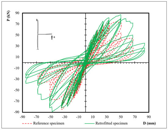
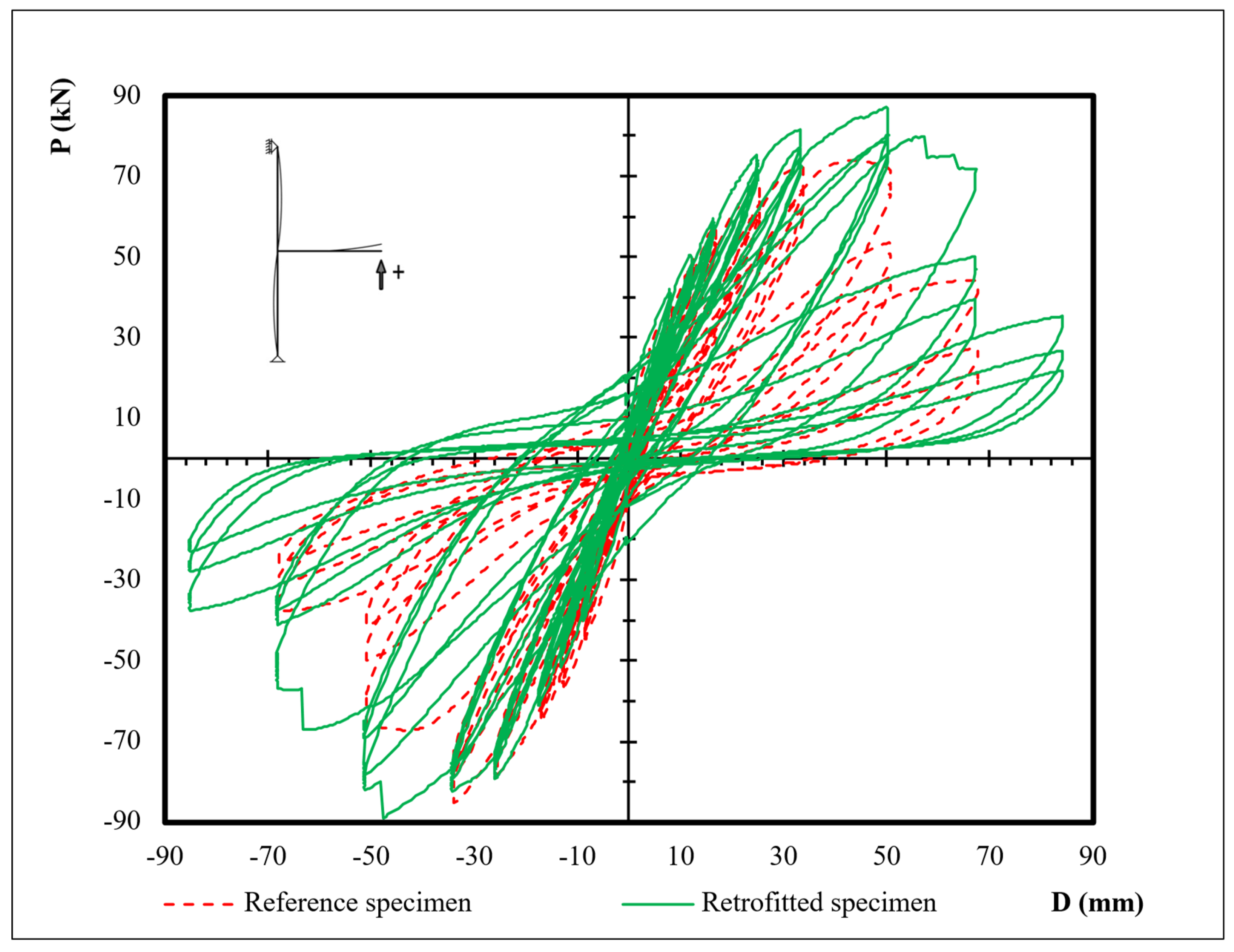
The hysteretic response of BCJ subassemblages is a key indicator of their structural performance under seismic loading. In particular, their shear behavior, post-peak response, ductility, and energy dissipation capacity are among the most important parameters governing their seismic performance. Accordingly, the load–deformation hysteresis curves of the reference and retrofitted specimens are presented in Figure 7. The reference specimen reached its maximum absolute lateral load during the first cycle of the fifth loading step and maintained its load-carrying capacity until the first positive cycle of the sixth loading step. Thereafter, rapid strength degradation was observed, indicating the onset of brittle failure. Furthermore, during the seventh loading step, severe concrete crushing developed within the joint core due to extensive shear cracking; consequently, the specimen was not subjected to the eighth loading step. In contrast, the retrofitted specimen reached its maximum absolute lateral load during the first cycle of the sixth loading step, at which rupture of the C-FRP sheet was first observed. The retrofitted specimen exhibited a considerably more gradual post-peak strength degradation, maintaining its load-carrying capacity over larger deformation demands. Consequently, wider and more stable hysteresis loops were developed, indicating a more ductile response and greater energy dissipation by the retrofitted specimen relative to the reference specimen.
Figure 7.
Hysteretic response of BCJ specimens.
A quantitative comparison of the hysteretic response further highlights the differences between the two tested specimens. The reference specimen developed positive and negative peak lateral loads of 74.02 kN and −85.17 kN, respectively, whereas the corresponding values for the retrofitted specimen were 87.27 kN and −88.90 kN. Thus, the retrofitted specimen exhibited a 17.9% increase in positive-peak lateral resistance and a 4.4% increase in the magnitude of the negative-peak load. The positive peak load occurred at 3.0% story drift for both specimens, while the negative peak load was reached at 2.0% drift for the reference specimen and 3.0% drift for the retrofitted specimen.
The secant stiffness values further quantify the different degradation patterns observed in the hysteretic response. At 0.5% story drift, the reference and retrofitted specimens exhibited comparable secant stiffness values of 4.97 and 4.82 kN/mm, respectively. At 3% drift, the corresponding values decreased to 1.39 and 1.73 kN/mm, representing stiffness reductions of 72.0% and 64.1%, respectively, relative to the values measured at 0.5% drift. At 4% drift, the secant stiffness further decreased to 0.60 kN/mm for the reference specimen and 1.08 kN/mm for the retrofitted specimen, corresponding to reductions of 87.9% and 77.6%, respectively. Thus, at 4% drift, the secant stiffness of the retrofitted specimen was approximately 80% higher than that of the reference specimen, demonstrating a slower rate of stiffness degradation at higher deformation demands. Progressive stiffness degradation under cyclic loading is generally associated with the accumulation and evolution of damage in cementitious materials, as also reported in recent studies examining stiffness degradation at both the material and structural-component scales [67,72].
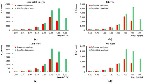
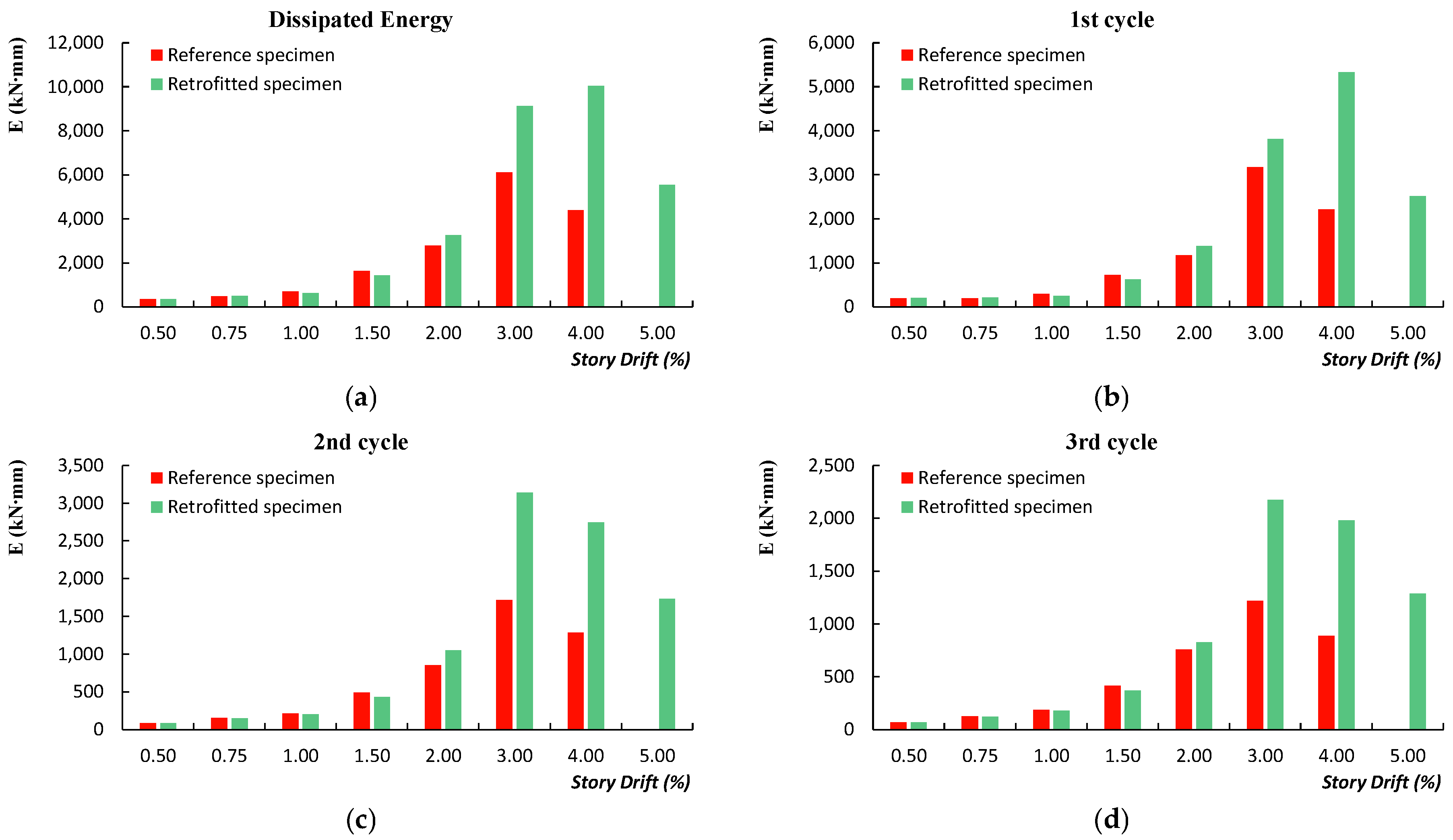
Additionally, the total dissipated energy of each step is presented in Figure 8a, while the energy dissipated during the first, second, and third loading cycles of each loading step is presented in Figure 8b, Figure 8c and Figure 8d, respectively. The dissipated energy of each cycle was calculated as the area enclosed by the corresponding load–displacement hysteresis loop, while the total dissipated energy at each loading step was calculated as the sum of the energy dissipated during the three corresponding loading cycles. During the initial loading stages, both specimens exhibited comparable energy dissipation, reflecting their similar response before the onset of significant damage. As the imposed deformation increased, the retrofitted specimen consistently dissipated more energy than the reference specimen in all three loading cycles. The overall evolution of dissipated energy with increasing loading step was similar across the three consecutive cycles for both specimens, although its magnitude progressively decreased from the first to the third cycle. The difference between the two specimens became particularly pronounced from the third loading step onwards and reached its maximum at the fourth and fifth loading steps. This behavior is consistent with the broader and more stable hysteresis loops observed in the retrofitted specimen and with its delayed strength degradation, allowing greater inelastic deformations to be sustained while maintaining load-carrying capacity. Consequently, within the present comparison, the retrofitted specimen exhibited greater energy dissipation capacity than the reference specimen. Considering the entire loading history, the cumulative dissipated energy, calculated as the sum of the energy dissipated over all completed loading cycles, was kN·mm for the reference specimen and kN·mm for the retrofitted specimen, corresponding to an increase of 54.0%.
Figure 8.
Energy dissipation capacity of the reference and retrofitted BCJ specimens. (a) Total dissipated energy at each loading step. (b) Dissipated energy during the first loading cycle of each loading step. (c) Dissipated energy during the second loading cycle of each loading step. (d) Dissipated energy during the third loading cycle of each loading step.
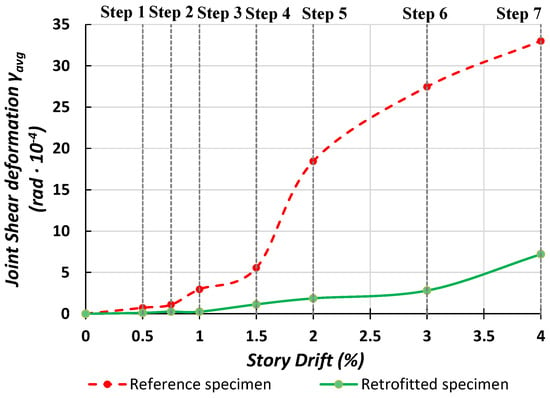
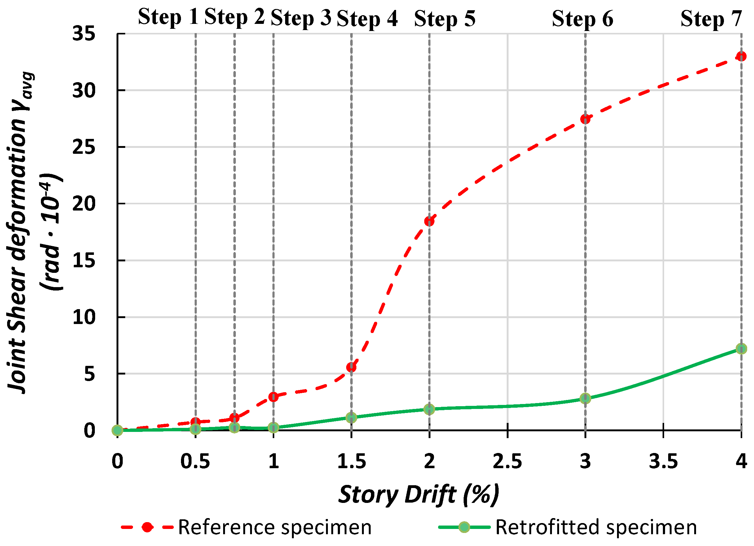
Figure 9 presents the evolution of joint shear deformation as story drift increases for both specimens. Up to approximately 1% story drift, the two specimens exhibited relatively low shear deformation. Beyond this level, however, the reference specimen experienced a rapid increase in joint shear deformation, reflecting the extensive development of shear cracking within the joint core. In contrast, the retrofitted specimen maintained substantially lower shear deformation throughout the loading process, consistent with restrained development of shear cracking within the joint core. At 2% story drift, the average joint shear deformation, , was rad for the reference specimen and rad for the retrofitted specimen, corresponding to an 89.9% reduction. At 3% drift, the corresponding values were rad and rad, respectively, representing an 89.7% reduction. At the maximum common drift level of 4%, the average joint shear deformation was rad for the reference specimen and rad for the retrofitted specimen, corresponding to a 78.2% reduction. These quantitative results demonstrate that the strengthening scheme substantially restrained joint shear deformation in the tested retrofitted specimen, particularly at higher drift demands.
Figure 9.
Evolution of joint shear deformations in the tested specimens.
Overall, the structural response observed in the present investigation is generally consistent with trends reported in previous experimental investigations of strengthened RC BCJs. In particular, the comparative assessment presented in [67] reports improvements in energy dissipation at large drift levels of approximately 32–42% for different strengthening configurations considered in previous studies. In the present investigation, the retrofitted specimen similarly exhibited greater energy dissipation than the reference specimen at higher drift demands, while its cumulative dissipated energy over the respective complete loading histories was 54.0% higher. Direct quantitative comparison should, however, be made with caution, since differences in specimen geometry, reinforcement detailing, strengthening configuration, material properties, loading protocol, and definition of the reported performance indices can significantly affect the measured response. Nevertheless, the present findings are consistent with the broader trend reported in [67], indicating improved cyclic and energy-dissipation response following strengthening of RC BCJs.
3.2. Continuous SHM of BCJs Throughout the Loading Sequence
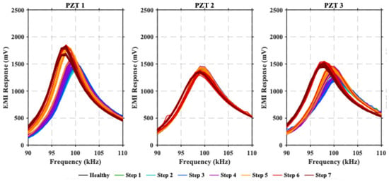
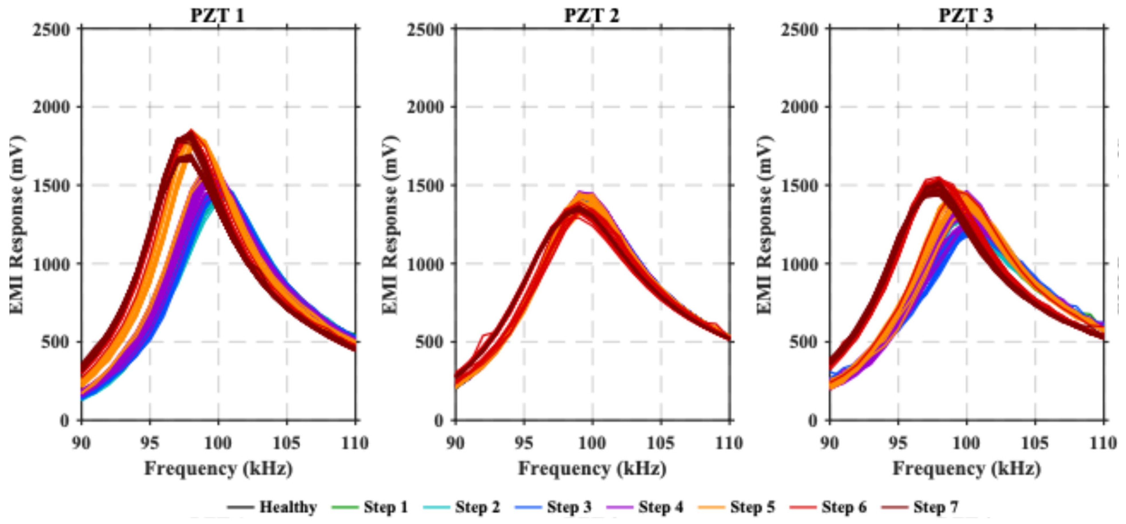
As previously mentioned, the present study also evaluates the applicability of the EMI-based SHM technique for continuously tracking changes in the structural condition of bare and retrofitted RC BCJs throughout the quasi-static loading sequence, rather than only at selected characteristic damage states. Figure 10 presents the EMI signatures recorded by the three PZT sensors installed on the reference specimen in the healthy state and during the loading sequence.
Figure 10.
The EMI responses of the PZTs of the reference specimen.
The EMI signatures of the reference specimen exhibited progressive but relatively smooth variations throughout the loading history. For all three PZT transducers, the resonance peaks remained within a similar amplitude range, while gradual changes in peak amplitude, shape, and frequency position were observed with increasing loading level. These variations were temporally consistent with the progressive development of cracking and associated changes in the local structural condition within the joint region. PZT1 and PZT3 exhibited more pronounced changes than PZT2, consistent with the observed crack pattern, as major cracks propagated directly beneath or in the immediate vicinity of these sensors. In contrast, PZT2 showed comparatively smaller variations because the dominant cracks developed near, but not directly beneath, its location. Unlike the retrofitted specimen, no abrupt divergence or excessive increase in the EMI signatures was observed, indicating that the sensor–structure coupling was maintained throughout the test. Overall, the observed EMI variations were consistent with the progressive damage evolution of the reference BCJ during cyclic loading.
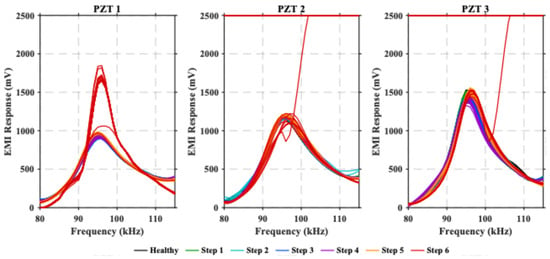
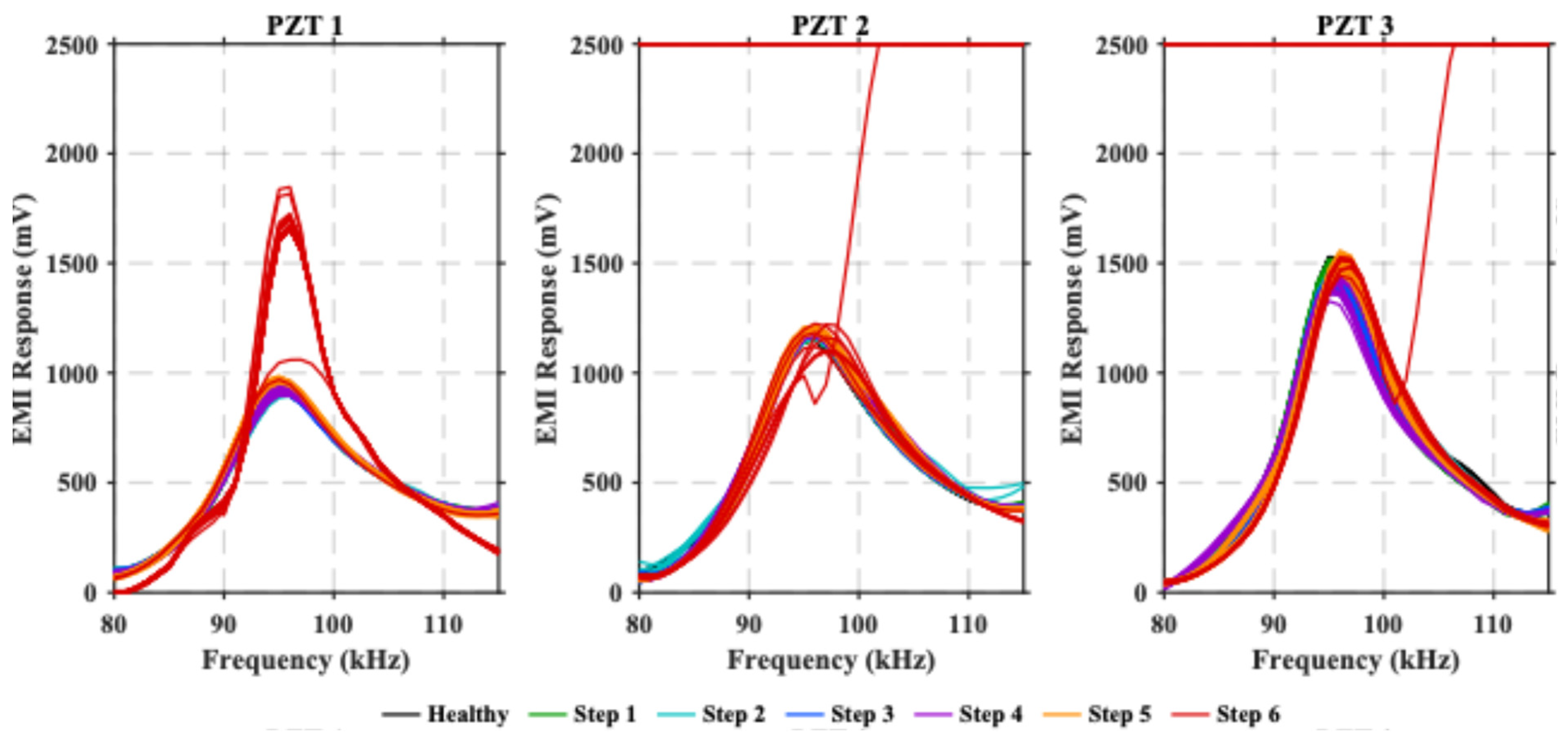
Similarly, Figure 11 shows the EMI signatures recorded by the three PZT sensors installed on the retrofitted specimen in the healthy state and during the loading sequence. As the loading sequence progressed, the PZT sensors exhibited gradual changes in their EMI signatures relative to the healthy condition. During the initial loading steps, only minor deviations from the healthy signatures were observed; progressively, changes in the amplitude, shape, and frequency position of the resonance characteristics became evident as the applied deformation increased. Up to the fifth loading step, the characteristic frequency-domain patterns of the EMI signatures were generally retained, consistent with progressive changes in the monitored structural condition. It should be noted that direct visual mapping of the underlying concrete cracking and progressive C-FRP–concrete interfacial damage was not possible during testing because the externally bonded C-FRP sheet covered the joint surface. Consequently, the interpretation of damage evolution in the retrofitted specimen is restricted to the experimentally observable failure events and their correspondence with the measured structural and EMI responses.
Figure 11.
The EMI responses of the PZTs of the retrofitted specimen.
However, a distinctly different response was observed during the sixth loading step, which coincided with rupture of the C-FRP sheet and deterioration of the PZT bonding condition. In particular, PZT2 and PZT3 experienced complete epoxy bond failure, resulting in a loss of electromechanical coupling with the monitored substrate and disrupting sensor functionality. Consequently, PZT2 and PZT3 ceased to be capable of reliable monitoring thereafter. On the contrary, PZT1 experienced only partial deterioration of its bonding interface and remained operational, although its EMI signature was also substantially affected by the altered coupling condition. Therefore, the pronounced changes observed at this final loading stage cannot be attributed solely to further deterioration of the concrete joint. Instead, they reflect the combined effects of strengthening-system failure and the associated alteration or loss of sensor–structure coupling.
This distinction is important for the practical interpretation of EMI measurements. RMSD alone cannot determine whether a change in the EMI response originates from structural deterioration or from degradation of the sensor–structure coupling. Changes observed while the characteristic resonance response remains identifiable may provide information about the evolving condition of the monitored system; however, an abrupt and substantial distortion of the frequency-domain signature, particularly when accompanied by a loss of the characteristic resonance behavior, may indicate compromised sensor–structure coupling. Accordingly, the EMI responses recorded after debonding were not considered reliable indicators of the subsequent structural condition. The observations further highlight the importance of monitoring sensor integrity and of providing adequate sensor redundancy in practical EMI-based SHM applications.
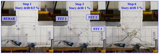
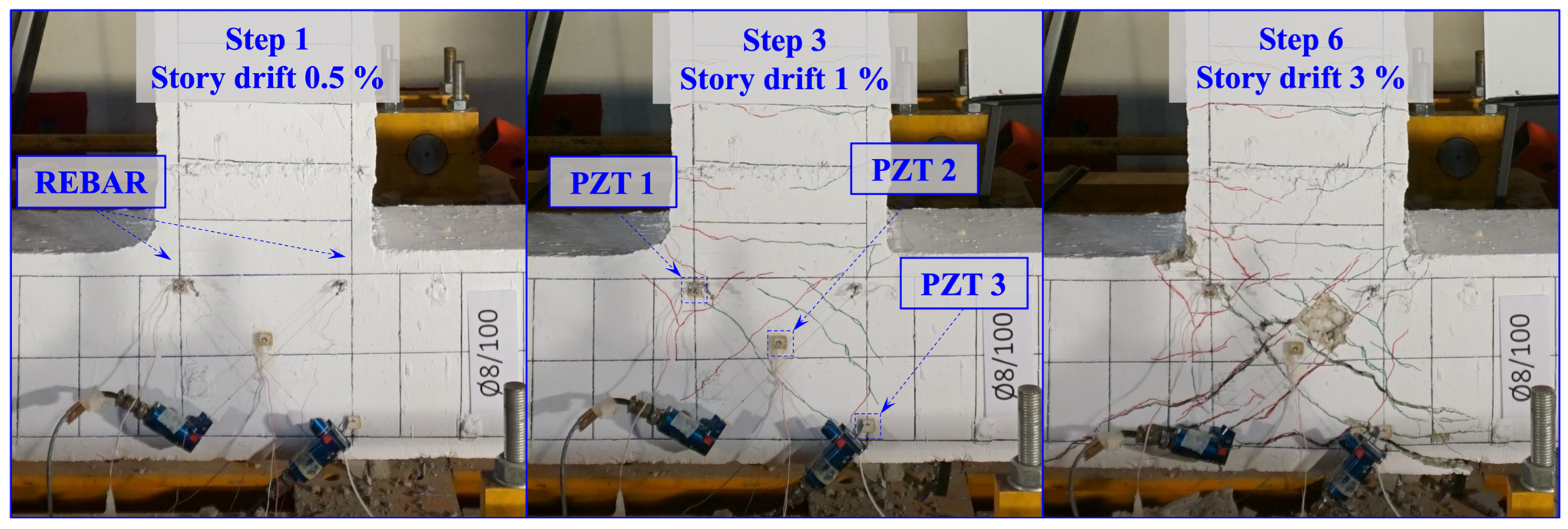
To further examine the spatial relationship between the sensor responses and the experimentally observed damage evolution, Figure 12 presents the crack pattern of the reference specimen at representative story-drift levels. At 0.5% story drift, cracking within the monitored region remained relatively limited. As the imposed drift increased, diagonal cracks progressively developed and propagated across the joint region. At Step 6, corresponding to 3% story drift, major cracks were observed to pass directly beneath PZT1 and PZT3. In contrast, the predominant cracks developed around the region monitored by PZT2 without passing directly beneath the sensor. Figure 12 therefore provides direct visual evidence of the spatial relationship between the evolving crack field and the locations of the individual PZT transducers. The location of the longitudinal beam reinforcement is also indicated, as the responses of PZT1 and PZT3 may additionally have been influenced by local bond-related effects associated with the reinforcement anchorage region. For the retrofitted specimen, the externally bonded C-FRP sheet covered the critical joint region and therefore prevented direct visual observation of the development of the underlying concrete cracks during loading. Consequently, a crack-evolution sequence comparable to that presented in Figure 12 for the reference specimen could not be documented.
Figure 12.
Experimentally observed crack evolution in the reference BCJ specimen at representative story-drift levels.
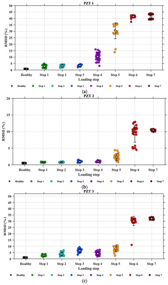
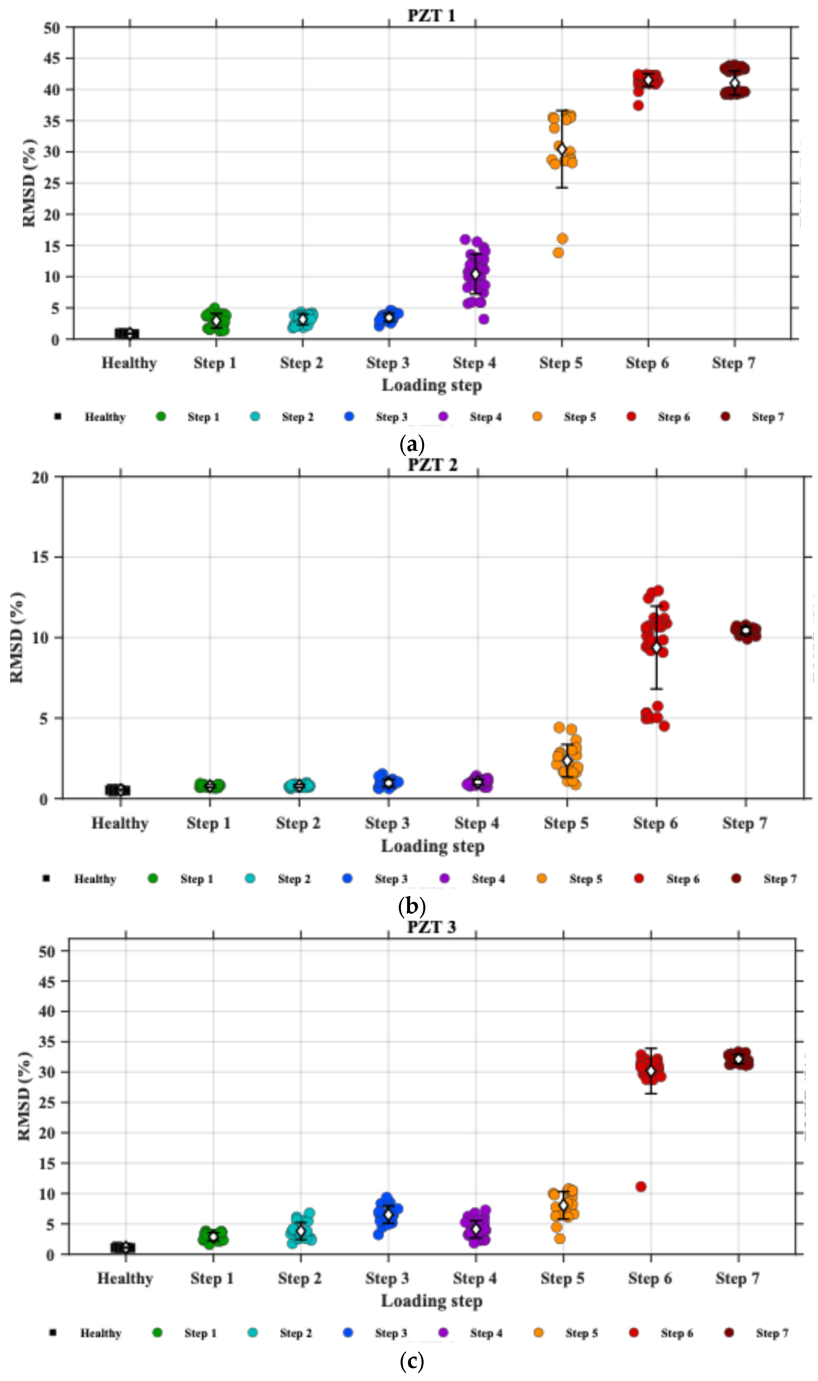
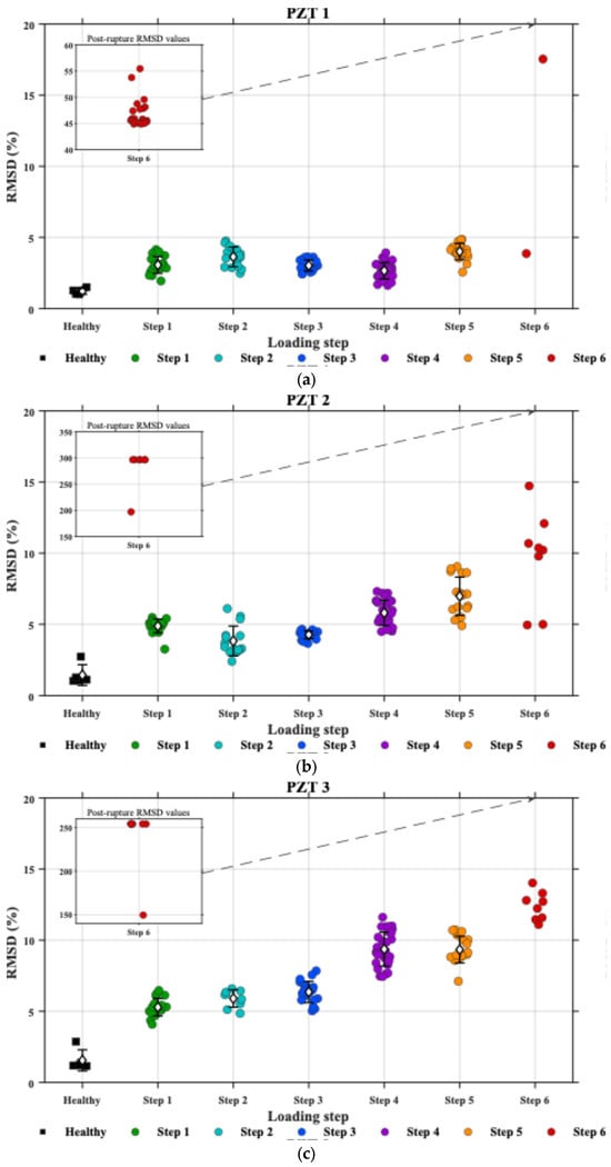
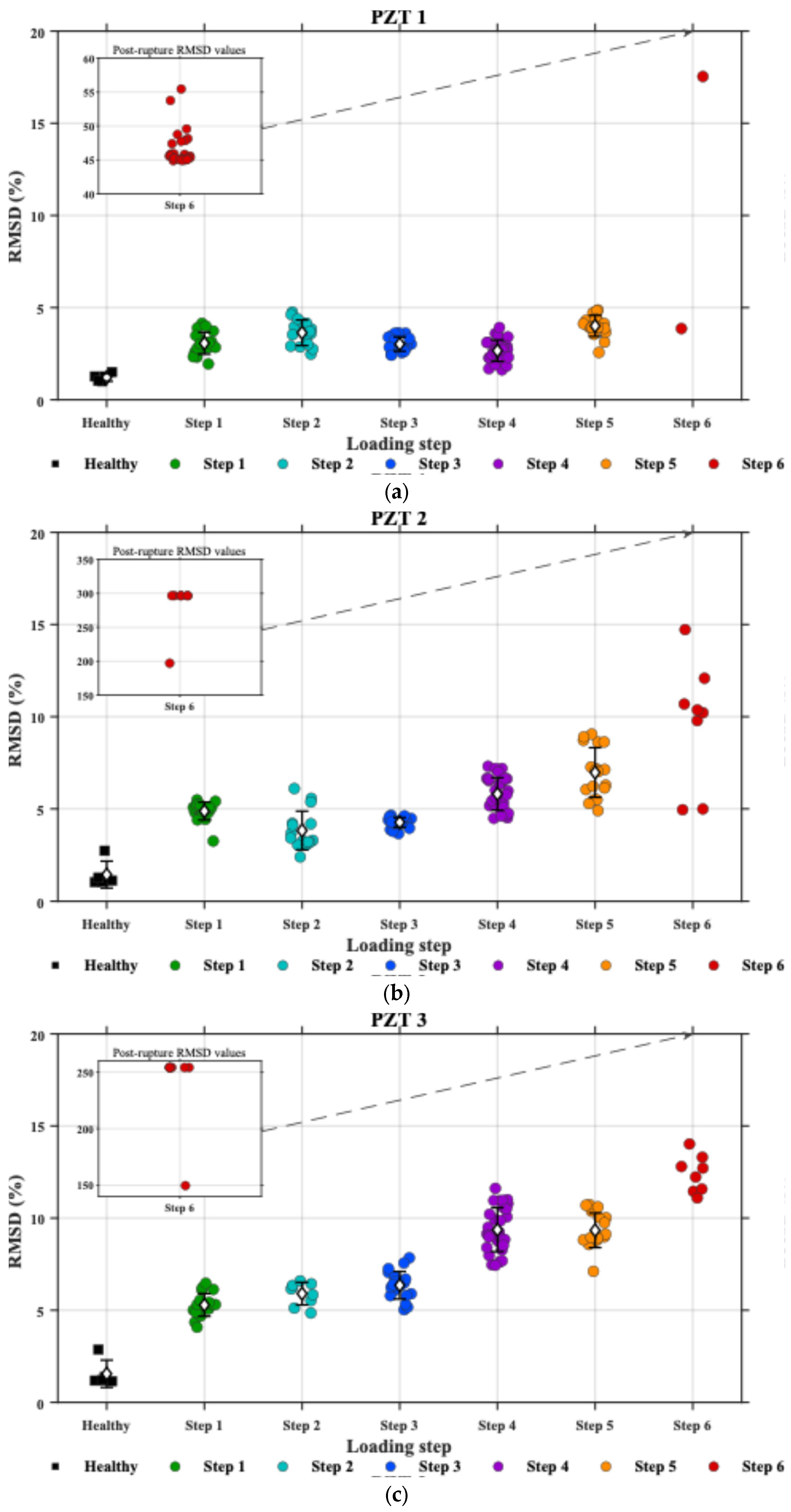
In Figure 13 and Figure 14, the individual points correspond to RMSD values obtained from consecutive EMI signatures acquired within each loading step, while the white diamond markers and error bars indicate the mean and ±1 standard deviation, respectively, where applicable. Figure 13 presents the evolution of the RMSD index for the three PZT sensors installed on the reference BCJ specimen. Overall, the RMSD values increased progressively throughout the loading history, coinciding with the gradual accumulation of experimentally observed damage within the joint. The increase became more pronounced after the fourth loading step, when extensive diagonal shear cracking and progressive degradation of the joint stiffness were observed. Differences were also evident among the responses of the three sensors. As shown in Figure 12, as the imposed deformation increased, the major cracks passed directly beneath PZT1 and PZT3, whereas the predominant cracks developed around PZT2 without passing directly beneath the sensor. This spatial correspondence is consistent with the more pronounced EMI modifications and higher RMSD values recorded by PZT1 and PZT3 relative to PZT2. However, crack proximity should not be regarded as the sole mechanism governing these differences. PZT1 and PZT3 were also positioned directly above the longitudinal beam reinforcement; therefore, bond-related microcracking in the anchorage region and possible reinforcement slip may also have contributed to the local mechanical changes sensed by these transducers. Accordingly, the present observations establish a spatial correspondence between the sensor responses and the experimentally observed damage field, but do not permit the individual contributions of cracking and reinforcement–concrete bond effects to be quantitatively separated. Despite the differences in sensor sensitivity, all three PZT transducers exhibited progressive changes in their EMI responses that were consistent with the experimentally observed evolution of structural damage, demonstrating the potential of the EMI-based SHM technique for continuously monitoring the deterioration of RC BCJs subjected to quasi-static seismic loading.
Figure 13.
RMSD index values obtained from consecutive EMI signatures of the reference specimen. White diamond markers and error bars indicate the mean and ±1 standard deviation, respectively. (a) PZT 1; (b) PZT 2; (c) PZT 3.
Figure 14.
RMSD index values obtained from consecutive EMI signatures of the retrofitted specimen. White diamond markers and error bars indicate the mean and ±1 standard deviation, respectively. (a) PZT 1; (b) PZT 2; (c) PZT 3.
Figure 14 presents the evolution of the RMSD index for the three PZT sensors installed on the retrofitted BCJ. The RMSD values remained comparatively low to moderate during the initial five loading steps, signifying that the EMI signatures maintained a relatively high degree of similarity to their healthy baseline responses. This behavior aligns with the observed capacity of the strengthening scheme to inhibit crack propagation and postpone significant alterations in the monitored joint region. A pronounced increase in RMSD was observed during the sixth loading step, coinciding with rupture of the C-FRP sheet and deterioration of the PZT bonding interfaces. In particular, complete epoxy-bond failure occurred for PZT2 and PZT3, resulting in the loss of their electromechanical coupling with the monitored substrate and their functionality. The large RMSD values obtained from these sensors at this stage primarily reflect the significant deviation of their EMI signatures from the healthy baseline and should not be interpreted quantitatively as an indicator of a proportional increase in structural damage severity. PZT1 remained partially bonded and continued to provide a measurable EMI response, although its signature was also affected by the altered coupling condition. For clarity, the post-rupture RMSD values obtained during Step 6 that exceed the scale of the main axis are presented separately in the corresponding insets of Figure 14.
These observations underscore a significant limitation of RMSD when used as a standalone damage index. RMSD measures the magnitude of change relative to a baseline condition but does not elucidate the physical origin of such change. Therefore, RMSD alone is insufficient to definitively distinguish between structural deterioration and degradation or loss of sensor–structure coupling. In the current experiment, the sudden increase in RMSD at the sixth loading step coincided with the independently observed rupture of the C-FRP sheet and PZT debonding, along with notable alterations in the corresponding frequency-domain EMI signatures. Consequently, the responses recorded at Step 6 from the debonded sensors should be interpreted as measurements compromised by coupling issues rather than as direct quantitative indicators of joint damage severity.
For practical SHM implementation, RMSD should therefore be interpreted together with the characteristics of the underlying frequency-domain EMI signature and an assessment of sensor integrity. Complementary indicators, such as changes in resonance-peak amplitude or correlation-based metrics like the correlation coefficient deviation (CCD), could also be employed to flag abrupt changes potentially associated with degradation or loss of sensor coupling. The combined consideration of RMSD and sensor-integrity-sensitive features could improve the robustness of EMI-based damage interpretation, particularly when sensors are installed on externally bonded strengthening materials that may themselves debond or rupture.
The present study is subject to several limitations. The experimental campaign was designed to investigate the evolution of EMI responses as cyclic damage increased, rather than to establish a validated damage-detection threshold. Accordingly, repeatability across nominally identical specimens, false-alarm probability, and statistically defined detection thresholds were not evaluated. These aspects, together with long-term sensor-coupling stability, require dedicated validation using repeated tests and a larger experimental dataset before the method can be considered suitable for field-scale continuous SHM.
Beyond conventional damage indices, a data-driven classification approach based on machine learning techniques, including artificial neural networks, could provide a promising means of distinguishing EMI signature changes associated with structural deterioration from those caused by PZT debonding. Such an approach could exploit multiple features extracted from the frequency-domain response, or potentially the complete EMI signature, to classify different structural and sensor-coupling conditions. However, the development and validation of such a classifier requires a sufficiently large and representative labeled dataset containing independently identified cases of structural damage, partial PZT debonding, complete PZT debonding, and their combined occurrence. Such a dataset was not available within the scope of the present experimental campaign. The development of validated data-driven approaches for discriminating structural damage from sensor-coupling degradation therefore represents an important direction for future research.
The RMSD evolution of each specimen should primarily be interpreted relative to its own baseline and in conjunction with the experimentally observed damage progression. In the reference specimen, the progressive increase in RMSD coincided with the experimentally observed development of joint shear cracking. In the retrofitted specimen, relatively limited changes in RMSD with respect to its own baseline were observed during the first five loading steps, followed by abrupt changes at the sixth loading step, when rupture of the C-FRP sheet and deterioration of the PZT bonding condition and functionality occurred. Within each specimen, these trends provide useful indications of changes in the local structural state sensed by the corresponding PZT configuration.
Direct quantitative comparison of the RMSD magnitudes between the two specimens is not appropriate because, although the same EMI-based monitoring methodology was employed, the PZT sensors were coupled to different substrates: directly to concrete in the reference specimen and to the externally bonded C-FRP sheets in the retrofitted specimen. The measured EMI response is therefore influenced not only by structural damage evolution but also by the local PZT–adhesive–substrate system, including differences in substrate stiffness, interfacial conditions, and dynamic characteristics. This distinction is particularly relevant for the retrofitted specimen, which constitutes a multi-material system in which concrete cracking, adhesive/interface degradation, C-FRP–concrete debonding, C-FRP rupture, and changes in sensor coupling may interact during loading. Accordingly, differences in RMSD magnitude between the two specimens should not be interpreted as direct quantitative evidence of differences in structural-damage severity. Instead, RMSD is considered here as a local damage-sensitive indicator, with cross-specimen observations restricted to qualitative associations with independently observed cracking and failure events. Furthermore, the response of an individual PZT sensor depends on its location relative to the evolving damage field. Recent observations of crack-connectivity-related damage evolution in cementitious composites have shown that damage develops through spatially heterogeneous processes involving defect and crack initiation, coalescence, and subsequent localization [73]. Consequently, changes in the response of a particular PZT sensor may be influenced by its proximity to an evolving local damage zone and should not necessarily be interpreted as proportional changes in the global damage state of the specimen. In particular, the large RMSD values recorded after C-FRP rupture cannot be attributed solely to structural damage, as they include a substantial contribution from the deterioration of sensor–structure coupling.
4. Conclusions
This study experimentally evaluated the seismic performance and SHM of two full-scale RC exterior BCJs comprising one reference specimen and one specimen retrofitted using a hybrid retrofit scheme of NSM C-FRP ropes and externally bonded C-FRP sheets. The experimental results showed that, relative to the reference specimen, the retrofitted specimen exhibited a moderately higher load-carrying capacity, delayed joint shear deterioration, reduced joint shear deformation, and improved energy dissipation capacity. The reduced joint shear deformation was consistent with restrained development of diagonal shear cracking within the joint core, together with more gradual stiffness degradation and a more stable hysteretic response under quasi-static cyclic loading.
The EMI-based SHM technique captured progressive changes in the monitored structural condition during cyclic loading. For the reference specimen, the evolution of the EMI responses and RMSD values was consistent with the experimentally observed progression of joint cracking. For the retrofitted specimen, relatively limited variations in the EMI responses of the PZT sensors, reflected in comparatively low RMSD values, were observed during the initial loading stages, whereas pronounced changes occurred following rupture of the externally bonded C-FRP sheet and deterioration of the PZT bonding condition. These observations demonstrate that RMSD is sensitive to changes in the monitored PZT–structure system; however, it should not be interpreted as a damage-specific indicator, particularly when deterioration of sensor–structure coupling may occur.
The experimental observations further showed that the response of individual PZT transducers depends on their location relative to the evolving damage field and on the integrity of their bonding interface. Consequently, practical implementation of EMI-based monitoring in retrofitted RC members would require appropriate sensor placement, monitoring of sensor integrity, and sufficient sensor redundancy. Within the limitations of the present experimental investigation, the results demonstrate the potential of combining hybrid C-FRP strengthening with EMI-based SHM for monitoring the condition of retrofitted RC BCJs. Furthermore, because only one specimen was examined per configuration, variability among specimens could not be quantified. Therefore, the differences observed between the reference and retrofitted specimens should be regarded as demonstrative experimental findings rather than statistically validated retrofit effects. Further experimental validation involving repeated specimens, larger datasets, and assessment of long-term sensor-coupling stability is required before the proposed monitoring approach can be reliably extended to field-scale continuous SHM applications.
Author Contributions
Conceptualization, E.G., G.M.S., M.C.N. and N.A.P.; methodology, E.G., G.M.S., M.C.N. and N.A.P.; validation, E.G., G.M.S., M.C.N. and N.A.P.; investigation, E.G., G.M.S., M.C.N. and N.A.P.; data curation, G.M.S. and M.C.N.; writing—original draft preparation, G.M.S. and M.C.N.; writing—review and editing, E.G., G.M.S., M.C.N. and N.A.P.; visualization, E.G., G.M.S., M.C.N. and N.A.P. All authors have read and agreed to the published version of the manuscript.
Funding
This research received no external funding.
Institutional Review Board Statement
Not applicable.
Informed Consent Statement
Not applicable.
Data Availability Statement
The raw data supporting the conclusions of this article will be made available by the authors on request.
Acknowledgments
The authors wish to thank SIKA Hellas for supplying the C-FRP reinforcements and filling materials (impregnating resin and epoxy paste), including, in particular, Nikos Anagnostopoulos for his advice and support in strengthening the application of the tested beams.
Conflicts of Interest
The authors declare no conflicts of interest.
References
- de Luca, F.; Woods, G.E.D.; Galasso, C.; D’Ayala, D. RC Infilled Building Performance against the Evidence of the 2016 EEFIT Central Italy Post-Earthquake Reconnaissance Mission: Empirical Fragilities and Comparison with the FAST Method. Bull. Earthq. Eng. 2018, 16, 2943–2969. [Google Scholar] [CrossRef] [Scilit]
- Eslami, A.; Ronagh, H.R. Effect of FRP Wrapping in Seismic Performance of RC Buildings with and without Special Detailing—A Case Study. Compos. Part B Eng. 2013, 45, 1265–1274. [Google Scholar] [CrossRef] [Scilit]
- Tsonos, A.D.G.; Kalogeropoulos, G.I.; Iakovidis, P.E.; Konstantinidis, D. Seismic Retrofitting of Pre-1970 RC Bridge Columns Using Innovative Jackets. Int. J. Struct. Eng. 2017, 8, 133. [Google Scholar] [CrossRef] [Scilit]
- Tsonos, A.D.G. Model for the Evaluation of the Beam-Column Joint Ultimate Strength—A More Simplified Version. Earthq. Struct. 2019, 16, 141–148. [Google Scholar] [CrossRef]
- Paulay, T.; Scarpas, A. The Behaviour of Exterior Beam-Column Joints. Bull. N. Z. Soc. Earthq. Eng. 1981, 14, 131–144. [Google Scholar] [CrossRef] [Scilit]
- Sapidis, G.M.; Naoum, M.C.; Papadopoulos, N.A.; Golias, E.; Karayannis, C.G.; Chalioris, C.E. A Novel Approach to Monitoring the Performance of Carbon-Fiber-Reinforced Polymer Retrofitting in Reinforced Concrete Beam–Column Joints. Appl. Sci. 2024, 14, 9173. [Google Scholar] [CrossRef] [Scilit]
- Yang, X.; Dong, Y.; Liu, X.; Qiu, T.; Zhou, J. Seismic Behavior of Concrete Beam-Column Joints Reinforced with Steel-Jacketed Grouting. Buildings 2024, 14, 3239. [Google Scholar] [CrossRef] [Scilit]
- Kharwar, K.L.; Maurya, K.K.; Rawat, A. Retrofitting Techniques of Damaged Concrete Structure for Environment Concern: A Review. Mater. Today Proc. 2022, 65, 1161–1168. [Google Scholar] [CrossRef] [Scilit]
- Bindhu, K.R.; Mohana, N.; Sivakumar, S. New Reinforcement Detailing for Concrete Jacketing of Nonductile Exterior Beam–Column Joints. J. Perform. Constr. Facil. 2016, 30, 04014192. [Google Scholar] [CrossRef] [Scilit]
- Gholampour, A.; Hassanli, R.; Mills, J.E.; Vincent, T.; Kunieda, M. Experimental Investigation of the Performance of Concrete Columns Strengthened with Fiber Reinforced Concrete Jacket. Constr. Build. Mater. 2019, 194, 51–61. [Google Scholar] [CrossRef] [Scilit]
- Karayannis, C.G.; Chalioris, C.E.; Sirkelis, G.M. Local Retrofit of Exterior RC Beam–Column Joints Using Thin RC Jackets—An Experimental Study. Earthq. Eng. Struct. Dyn. 2008, 37, 727–746. [Google Scholar] [CrossRef] [Scilit]
- Xue, J.; Ren, G.; Zhang, J.; Xu, D. Seismic Performance of Semi-Tenon Joints Reinforced by Steel Angle in Traditional Timber Buildings. Adv. Struct. Eng. 2020, 23, 2318–2332. [Google Scholar] [CrossRef] [Scilit]
- Shoukry, M.E.; Tarabia, A.M.; Abdelrahman, M.Z. Seismic Retrofit of Deficient Exterior RC Beam-Column Joints Using Steel Plates and Angles. Alex. Eng. J. 2022, 61, 3147–3164. [Google Scholar] [CrossRef] [Scilit]
- Zia, A.; Pu, Z.; Holly, I.; Umar, T.; Tariq, M.A.U.R. Development of an Analytical Model for the FRP Retrofitted Deficient Interior Reinforced Concrete Beam-Column Joints. Appl. Sci. 2022, 12, 2339. [Google Scholar] [CrossRef] [Scilit]
- Lin, J.-P.; Wu, Y.-F.; Smith, S.T. Width Factor for Externally Bonded FRP-to-Concrete Joints. Constr. Build. Mater. 2017, 155, 818–829. [Google Scholar] [CrossRef] [Scilit]
- Hosseini, A.S.; Bahaari, M.R.; Lesani, M. Experimental and Parametric Studies of SCFs in FRP Strengthened Tubular T-Joints under Axially Loaded Brace. Eng. Struct. 2020, 213, 110548. [Google Scholar] [CrossRef] [Scilit]
- Karayannis, C.G.; Sirkelis, G.M. Strengthening and Rehabilitation of RC Beam–Column Joints Using Carbon-FRP Jacketing and Epoxy Resin Injection. Earthq. Eng. Struct. Dyn. 2008, 37, 769–790. [Google Scholar] [CrossRef] [Scilit]
- del Rey Castillo, E.; Niroomandi, A.; Triantafillou, T. Seismic Retrofitting of Realistic Beam–Column Joints with Shear Failure Using FRP Sheets and FRP Anchors. J. Compos. Constr. 2024, 28, 05024001. [Google Scholar] [CrossRef] [Scilit]
- del Vecchio, C.; Di Ludovico, M.; Prota, A. Design Procedure for the FRCC Strengthening of Beam-Column Joints. In 10th International Conference on FRP Composites in Civil Engineering; Ilki, A., Ispir, M., Inci, P., Eds.; Lecture Notes in Civil Engineering; Springer International Publishing: Cham, Switzerland, 2022; Volume 198, pp. 1895–1903. [Google Scholar]
- Majumder, S.; Saha, S. Quasi-Static Cyclic Performance of RC Exterior Beam-Column Joint Assemblages Strengthened with Geosynthetic Materials. Structures 2021, 29, 1210–1228. [Google Scholar] [CrossRef] [Scilit]
- Esmaeeli, E.; Danesh, F.; Tee, K.F.; Eshghi, S. A Combination of GFRP Sheets and Steel Cage for Seismic Strengthening of Shear-Deficient Corner RC Beam-Column Joints. Compos. Struct. 2017, 159, 206–219. [Google Scholar] [CrossRef] [Scilit]
- Ghaderi Barmi, C.; Saghafi, M.H.; Golafshar, A. Providing a Strategy to Restore Damaged RC Beam-Column Joints with the Combination of CFRP and HPFRCC. Eng. Struct. 2024, 299, 117148. [Google Scholar] [CrossRef] [Scilit]
- Tsonos, A.-D.; Kalogeropoulos, G.; Iakovidis, P.; Bezas, M.-Z.; Koumtzis, M. Seismic Performance of RC Beam–Column Joints Designed According to Older and Modern Codes: An Attempt to Reduce Conventional Reinforcement Using Steel Fiber Reinforced Concrete. Fibers 2021, 9, 45. [Google Scholar] [CrossRef] [Scilit]
- Triantafyllou, G.G.; Rousakis, T.C.; Karabinis, A.I. Corroded RC Beams Patch Repaired and Strengthened in Flexure with Fiber-Reinforced Polymer Laminates. Compos. Part B Eng. 2017, 112, 125–136. [Google Scholar] [CrossRef] [Scilit]
- Perera, R.; Huerta, M.C.; Baena, M.; Barris, C. Analysis of FRP-Strengthened Reinforced Concrete Beams Using Electromechanical Impedance Technique and Digital Image Correlation System. Sensors 2023, 23, 8933. [Google Scholar] [CrossRef] [Scilit]
- Wang, H.; Li, C.; Song, S.; Wang, Y.; Meng, Q.; Li, F. Flexural Performance of Cracked Reinforced Concrete Beams Strengthened with Prestressed CFRP Sheets under Repeated Loads. Buildings 2023, 13, 2115. [Google Scholar] [CrossRef] [Scilit]
- Fanaradelli, T.; Rousakis, T.; Karabinis, A. Reinforced Concrete Columns of Square and Rectangular Section, Confined with FRP—Prediction of Stress and Strain at Failure. Compos. Part B Eng. 2019, 174, 107046. [Google Scholar] [CrossRef] [Scilit]
- Rousakis, T.C. Resilience Reserve of RC Columns Externally Confined with Composite Rope or FRP Sheet Under Seismic Overloads. In Proceedings of the International Conference on FRP Composites in Civil Engineering, Hong Kong, China, 14 December 2016; pp. 1033–1038. [Google Scholar]
- Karabini, M.; del Vecchio, C.; Rousakis, T.; di Ludovico, M.; Prota, A. Seismic Strengthening of External Beam-Column Joints with Plain Bars Using Minimally Invasive FRP Layouts. Eng. Struct. 2025, 345, 121517. [Google Scholar] [CrossRef] [Scilit]
- Baena, M.; Jahani, Y.; Torres, L.; Barris, C.; Perera, R. Flexural Performance and End Debonding Prediction of NSM Carbon FRP-Strengthened Reinforced Concrete Beams under Different Service Temperatures. Polymers 2023, 15, 851. [Google Scholar] [CrossRef] [Scilit]
- Sevillano, E.; Sun, R.; Perera, R.; Arteaga, A.; de Diego, A.; Cisneros, D. Comparison of PZT and FBG Sensing Technologies for Debonding Detection on Reinforced Concrete Beams Strengthened with External CFRP Strips Subjected to Bending Loads. Mater. Constr. 2016, 66, e088. [Google Scholar] [CrossRef] [Scilit]
- Antonopoulos, C.P.; Triantafillou, T.C. Experimental Investigation of FRP-Strengthened RC Beam-Column Joints. J. Compos. Constr. 2003, 7, 39–49. [Google Scholar] [CrossRef] [Scilit]
- Bakis, C.E.; Bank, L.C.; Brown, V.L.; Cosenza, E.; Davalos, J.F.; Lesko, J.J.; Machida, A.; Rizkalla, S.H.; Triantafillou, T.C. Fiber-Reinforced Polymer Composites for Construction—State-of-the-Art Review. J. Compos. Constr. 2002, 6, 73–87. [Google Scholar] [CrossRef] [Scilit]
- Cosenza, E.; Manfredi, G.; Realfonzo, R. Behavior and Modeling of Bond of FRP Rebars to Concrete. J. Compos. Constr. 1997, 1, 40–51. [Google Scholar] [CrossRef] [Scilit]
- Benavent, A.; Castro, E.; Gallego, A. Evaluation of Low-Cycle Fatigue Damage in RC Exterior Beam-Column Subassemblages by Acoustic Emission. Constr. Build. Mater. 2010, 24, 1830–1842. [Google Scholar] [CrossRef] [Scilit]
- Yan, S.; Ma, H.; Li, P.; Song, G.; Wu, J. Development and Application of a Structural Health Monitoring System Based on Wireless Smart Aggregates. Sensors 2017, 17, 1641. [Google Scholar] [CrossRef] [Scilit]
- Jiao, P.; Egbe, K.-J.I.; Xie, Y.; Matin Nazar, A.; Alavi, A.H. Piezoelectric Sensing Techniques in Structural Health Monitoring: A State-of-the-Art Review. Sensors 2020, 20, 3730. [Google Scholar] [CrossRef] [Scilit]
- Sapidis, G.M.; Naoum, M.C.; Papadopoulos, N.A. Electromechanical Impedance-Based Compressive Load-Induced Damage Identification of Fiber-Reinforced Concrete. Infrastructures 2025, 10, 60. [Google Scholar] [CrossRef] [Scilit]
- Naoum, M.C.; Sapidis, G.M.; Papadopoulos, N.A.; Voutetaki, M.E. An Electromechanical Impedance-Based Application of Realtime Monitoring for the Load-Induced Flexural Stress and Damage in Fiber-Reinforced Concrete. Fibers 2023, 11, 34. [Google Scholar] [CrossRef] [Scilit]
- Kocherla, A.; Subramaniam, K.V.L. Embedded Smart PZT-Based Sensor for Internal Damage Detection in Concrete under Applied Compression. Measurement 2020, 163, 108018. [Google Scholar] [CrossRef] [Scilit]
- Ai, D.; Luo, H.; Wang, C.; Zhu, H. Monitoring of the Load-Induced RC Beam Structural Tension/Compression Stress and Damage Using Piezoelectric Transducers. Eng. Struct. 2018, 154, 38–51. [Google Scholar] [CrossRef] [Scilit]
- Ai, D.; Mo, F.; Han, Y.; Wen, J. Automated Identification of Compressive Stress and Damage in Concrete Specimen Using Convolutional Neural Network Learned Electromechanical Admittance. Eng. Struct. 2022, 259, 114176. [Google Scholar] [CrossRef] [Scilit]
- Narayanan, A.; Subramaniam, K.V.L. Sensing of Damage and Substrate Stress in Concrete Using Electro-Mechanical Impedance Measurements of Bonded PZT Patches. Smart Mater. Struct. 2016, 25, 095011. [Google Scholar] [CrossRef] [Scilit]
- Zhang, C.; Yan, Q.; Panda, G.P.; Wu, W.; Song, G.; Vipulanandan, C. Real-Time Monitoring Stiffness Degradation of Hardened Cement Paste under Uniaxial Compression Loading through Piezoceramic-Based Electromechanical Impedance Method. Constr. Build. Mater. 2020, 256, 119395. [Google Scholar] [CrossRef] [Scilit]
- Wang, Z.; Chen, D.; Zheng, L.; Huo, L.; Song, G. Influence of Axial Load on Electromechanical Impedance (EMI) of Embedded Piezoceramic Transducers in Steel Fiber Concrete. Sensors 2018, 18, 1782. [Google Scholar] [CrossRef] [Scilit]
- Sapidis, G.M.; Kansizoglou, I.; Naoum, M.C.; Papadopoulos, N.A.; Tsintotas, K.A.; Voutetaki, M.E.; Gasteratos, A. Convolutional Neural Network for Specimen-Invariant Structural Health Monitoring of FRC Under Flexural Loading. Sensors 2026, 26, 2788. [Google Scholar] [CrossRef] [Scilit]
- Ai, D.; Du, L.; Li, H.; Zhu, H. Corrosion Damage Identification for Reinforced Concrete Beam Using Embedded Piezoelectric Transducer: Numerical Simulation. Measurement 2022, 192, 110925. [Google Scholar] [CrossRef] [Scilit]
- Hire, J.H.; Hosseini, S.; Moradi, F. Optimum PZT Patch Size for Corrosion Detection in Reinforced Concrete Using the Electromechanical Impedance Technique. Sensors 2021, 21, 3903. [Google Scholar] [CrossRef] [Scilit]
- Morwal, T.; Bansal, T.; Azam, A.; Talakokula, V. Monitoring Chloride-Induced Corrosion in Metallic and Reinforced/Prestressed Concrete Structures Using Piezo Sensors-Based Electro-Mechanical Impedance Technique: A Review. Measurement 2023, 218, 113102. [Google Scholar] [CrossRef] [Scilit]
- Talakokula, V.; Bhalla, S.; Gupta, A. Corrosion Assessment of Reinforced Concrete Structures Based on Equivalent Structural Parameters Using Electro-Mechanical Impedance Technique. J. Intell. Mater. Syst. Struct. 2014, 25, 484–500. [Google Scholar] [CrossRef] [Scilit]
- Bhalla, S.; Yang, Y.W.; Xu, J.F.; Soh, C.K. Damage Quantification Using EMI Technique. In Smart Materials in Structural Health Monitoring, Control and Biomechanics; Advanced Topics in Science and Technology in China; Springer: Berlin/Heidelberg, Germany, 2012; pp. 129–186. [Google Scholar]
- Sapidis, G.; Naoum, M.; Papadopoulos, N.; Voutetaki, M. Flexural Damage Evaluation in Fiber Reinforced Concrete Beams Using a PZT-Based Health Monitoring System. In International RILEM Conference on Synergising Expertise Towards Sustainability and Robustness of Cement-Based Materials and Concrete Structures; Jędrzejewska, A., Kanavaris, F., Azenha, M., Benboudjema, F., Schlicke, D., Eds.; RILEM Bookseries; Springer Nature: Cham, Switzerland, 2023; Volume 43, pp. 957–968. [Google Scholar]
- Narayanan, A.; Kocherla, A.; Subramaniam, K.V.L. PZT Sensor Array for Local and Distributed Measurements of Localized Cracking in Concrete. Smart Mater. Struct. 2018, 27, 075049. [Google Scholar] [CrossRef] [Scilit]
- Narayanan, A.; Subramaniam, K.V.L. Experimental Evaluation of Load-Induced Damage in Concrete from Distributed Microcracks to Localized Cracking on Electro-Mechanical Impedance Response of Bonded PZT. Constr. Build. Mater. 2016, 105, 536–544. [Google Scholar] [CrossRef] [Scilit]
- Naoum, M.C.; Papadopoulos, N.A.; Sapidis, G.M.; Chalioris, C.E. Advanced Structural Monitoring Technologies in Assessing the Performance of Retrofitted Reinforced Concrete Elements. Appl. Sci. 2024, 14, 9282. [Google Scholar] [CrossRef] [Scilit]
- Papadopoulos, N.A.; Naoum, M.C.; Sapidis, G.M.; Chalioris, C.E. Resilient and Sustainable Structures through EMI-Based SHM Evaluation of an Innovative C-FRP Rope Strengthening Technique. Appl. Mech. 2024, 5, 405–419. [Google Scholar] [CrossRef] [Scilit]
- Perera, R.; Torres, L.; Ruiz, A.; Barris, C.; Baena, M. An EMI-Based Clustering for Structural Health Monitoring of NSM FRP Strengthening Systems. Sensors 2019, 19, 3775. [Google Scholar] [CrossRef] [Scilit]
- Perera, R.; Montes, J.; Gómez, A.; Barris, C.; Baena, M. Unsupervised Autoencoders with Features in the Electromechanical Impedance Domain for Early Damage Assessment in FRP-Strengthened Concrete Elements. Eng. Struct. 2024, 315, 118458. [Google Scholar] [CrossRef] [Scilit]
- Sun, R.; Sevillano, E.; Perera, R. Debonding Detection of FRP Strengthened Concrete Beams by Using Impedance Measurements and an Ensemble PSO Adaptive Spectral Model. Compos. Struct. 2015, 125, 374–387. [Google Scholar] [CrossRef] [Scilit]
- Divsholi, B.S.; Yang, Y.W.; Bing, L. Monitoring Beam-Column Joint in Concrete Structures Using Piezo-Impedance Sensors. Adv. Mater. Res. 2009, 79–82, 59–62. [Google Scholar] [CrossRef] [Scilit]
- Chalioris, C.E.; Papadopoulos, N.A.; Sapidis, G.; Naoum, M.C.; Golias, E. EMA-Based Monitoring Method of Strengthened Beam-Column Joints. In Proceedings of the International ISCRAM Conference, Omaha, NE, USA, 21 December 2023; pp. 853–873. [Google Scholar]
- Naoum, M.; Sapidis, G.; Papadopoulos, N.; Golias, E.; Chalioris, C. Structural Health Monitoring of Reinforced Concrete Beam-Column Joints Using Piezoelectric Transducers. In International RILEM Conference on Synergising Expertise Towards Sustainability and Robustness of Cement-Based Materials and Concrete Structures; Jędrzejewska, A., Kanavaris, F., Azenha, M., Benboudjema, F., Schlicke, D., Eds.; RILEM Bookseries; Springer Nature: Cham, Switzerland, 2023; Volume 43, pp. 945–956. [Google Scholar]
- Liao, W.-I.; Hsiao, F.-P.; Chiu, C.-K.; Ho, C.-E. Structural Health Monitoring and Interface Damage Detection for Infill Reinforced Concrete Walls in Seismic Retrofit of Reinforced Concrete Frames Using Piezoceramic-Based Transducers Under the Cyclic Loading. Appl. Sci. 2019, 9, 312. [Google Scholar] [CrossRef] [Scilit]
- Choi, S.-K.; Tareen, N.; Kim, J.; Park, S.; Park, I. Real-Time Strength Monitoring for Concrete Structures Using EMI Technique Incorporating with Fuzzy Logic. Appl. Sci. 2018, 8, 75. [Google Scholar] [CrossRef] [Scilit]
- Mahmood, Y.; Yasir, N.; Quenette, K.; Badin, G.; Huang, Y.; Xu, L. Fiber-Optic Sensor-Based Structural Health Monitoring with Machine Learning: A Task-Oriented and Cross-Domain Review. Sensors 2026, 26, 2641. [Google Scholar] [CrossRef] [Scilit]
- Karayannis, C.G.; Golias, E.; Naoum, M.C.; Chalioris, C.E. Efficacy and Damage Diagnosis of Reinforced Concrete Columns and Joints Strengthened with FRP Ropes Using Piezoelectric Transducers. Sensors 2022, 22, 8294. [Google Scholar] [CrossRef] [Scilit]
- Golias, E.; Karayannis, C. Effect of C-FRP (Carbon Fiber Reinforced Polymer) Rope and Sheet Strengthening on the Shear Behavior of RC Beam-Column Joints. Fibers 2025, 13, 113. [Google Scholar] [CrossRef] [Scilit]
- Deng, J.; Li, X.; Zhu, M.; Rashid, K.; Wang, Q. Debonding Damage Detection of the CFRP-Concrete Interface Based on Piezoelectric Ceramics by the Electromechanical Impedance Method. Constr. Build. Mater. 2021, 303, 124431. [Google Scholar] [CrossRef] [Scilit]
- Park, S.; Kim, J.-W.; Lee, C.; Park, S.-K. Impedance-Based Wireless Debonding Condition Monitoring of CFRP Laminated Concrete Structures. NDT E Int. 2011, 44, 232–238. [Google Scholar] [CrossRef] [Scilit]
- Providakis, C.; Tsistrakis, S.; Voutetaki, M.; Tsompanakis, J.; Stavroulaki, M.; Agadakos, J.; Kampianakis, E.; Pentes, G.; Liarakos, E. An Innovative Active Sensing Platform for Wireless Damage Monitoring of Concrete Structures. Curr. Smart Mater. 2016, 1, 49–62. [Google Scholar] [CrossRef] [Scilit]
- Na, W.; Baek, J. A Review of the Piezoelectric Electromechanical Impedance Based Structural Health Monitoring Technique for Engineering Structures. Sensors 2018, 18, 1307. [Google Scholar] [CrossRef] [Scilit]
- Wang, C.; Liu, J.; Dai, Y.; Ma, Z. Elucidate CO2 Enhancement on Multiscale Mechanical Behavior and Stiffness Degradation of Fiber-Reinforced Recycled Aggregate Concrete under Cyclic Loading. J. Build. Eng. 2025, 111, 113298. [Google Scholar] [CrossRef] [Scilit]
- Wang, C.; Lu, Y. Crack-Connectivity-Related Damage Evolution in 3D-Printed Fiber-Reinforced Recycled Cementitious Composites Revealed by in-Situ 4D CT. Compos. Part B Eng. 2026, 325, 114005. [Google Scholar] [CrossRef] [Scilit]

Disclaimer/Publisher’s Note: The statements, opinions and data contained in all publications are solely those of the individual author(s) and contributor(s) and not of MDPI and/or the editor(s). MDPI and/or the editor(s) disclaim responsibility for any injury to people or property resulting from any ideas, methods, instructions or products referred to in the content. |
© 2026 by the authors. Licensee MDPI, Basel, Switzerland. This article is an open access article distributed under the terms and conditions of the Creative Commons Attribution (CC BY) license.