


Abstract
Post-disaster flexible suction requires perception of obstacle semantics and metric 3D geometry in cluttered, partially occluded workspaces. However, image-plane masks alone cannot provide physical height, surface slope, or obstacle clearance, while geometry without semantics cannot distinguish obstacle regions from obstacle-free sludge regions. This study proposes a multi-view semantic-geometric perception framework using synchronized arm-mounted RGB images. YOLO-LiteSeg provides obstacle instance masks, while Visual Geometry Grounded Transformer (VGGT) provides depth and camera parameters for multi-view reconstruction; checkerboard-based metric alignment converts reconstruction to physical scale. Projection-based 2D-to-3D semantic label transfer produces an obstacle-highlighted metric 3D scene representation for constraint-based suction-point selection. Across nine simulated conditions, YOLO-LiteSeg reduced parameters from 27.24 M to 2.61 M and giga floating-point operations from 52.37 to 5.47, while achieving 99.02% mean average precision at 0.50 intersection over union and 84.36% across thresholds from 0.50 to 0.95, with 4.56 ms inference. Reconstructed steepest-slope height profiles showed mean absolute errors below 2 cm. Enhanced and redundant camera configurations yielded a mean projected camera-position error of 4.02 cm and a root mean square error of 4.53 cm. The resulting 3D representation generated suction-point references satisfying predefined suction-depth and obstacle-clearance criteria, providing metrically interpretable spatial information for post-disaster flexible suction.
1. Introduction
Post-disaster workspaces created by earthquakes, landslides, and debris flows are typically cluttered, geometrically irregular, and locally unstable [1,2]. Rapid interpretation of visual information is therefore important for understanding disaster scenes and supporting field decisions [3]. In parallel, recent studies in construction and excavation have shown that intelligent equipment operating in unstructured terrain depends on reliable perception of terrain, obstacles, and task-relevant spatial information [4]. Flexible suction is a representative manipulation task in which the suction head must approach deformable sludge deposits while avoiding stones, shrubs, and other obstacles. Errors in obstacle localization, sludge-deposit thickness, local surface geometry, or cross-view spatial consistency may lead to collision, inefficient suction, pose disturbance, or secondary instability. For this task, image-level recognition alone is insufficient: the perception output must preserve obstacle identity while providing metric scene geometry and spatial information that can be used to determine a suction-point reference.
Pixel- and instance-level segmentation provides detailed obstacle semantics, but image-plane categories, boxes, and masks do not directly provide the metric quantities required for manipulation. Deep-learning-based disaster recognition and debris-flow detection have demonstrated the value of image semantics for extracting hazard-related information from complex scenes [3,5], while lightweight segmentation is especially relevant when visual processing must share limited computation with subsequent geometric processing. However, a 2D mask does not by itself provide physical height, surface slope, sludge-deposit thickness, or obstacle clearance. Projection-based work in unstructured construction environments has shown that image-derived semantics can be transferred to 3D point clouds to support spatial interpretation [6]. This motivates connecting reliable image-level obstacle segmentation with a metric 3D representation rather than treating the segmentation output as the final perception result.
The integration of semantic information with 3D geometry has already been explored in several application domains. Eye-in-hand semantic reconstruction has combined manipulator-mounted visual acquisition with semantic 3D modeling [7]. Semantic multi-view stereo methods have fused 2D segmentation with multi-view geometry to generate semantic point clouds [8], and semantically aware multi-view reconstruction has incorporated semantic consistency into sparse and dense reconstruction for complex urban scenes [9]. Other Applied Sciences studies have transferred deep image segmentation to 3D maps [10], constructed fast semantic maps from visual sequences [11], reviewed semantic mapping for mobile robots [12], and combined lightweight image segmentation with 3D semantic mapping in unstructured lawn scenes [13]. Direct semantic segmentation of 3D point clouds provides another route for adding category information to reconstructed geometry, particularly in construction applications [14]. These studies, together with SemanticFusion and more recent 2D-guided 3D instance and scene-representation methods [15,16,17], establish that semantics and geometry can be spatially associated in a common 3D representation. Accordingly, the research gap for post-disaster flexible suction is not the generic combination of 2D semantics and 3D geometry, but how to connect lightweight obstacle masks, metrically reconstructed sludge geometry, supporting camera-position information, and explicit suction constraints within one processing framework.
Metric 3D perception from RGB imagery introduces additional challenges. Image-based 3D reconstruction is attractive for engineering applications because it can recover spatial structure from image observations; however, reconstruction quality remains affected by viewpoint coverage, occlusion, texture, correspondence quality, and scale recovery [18]. Multi-view stereo methods continue to improve dense geometry recovery [19,20], while recent feed-forward models such as DUSt3R reduce dependence on conventional calibrated multi-view pipelines by directly predicting geometric relationships from image collections [21]. Applied Sciences studies have also demonstrated multi-view stereo reconstruction in natural scenes [22] and have used reconstructed soil surfaces to obtain engineering quantities such as soil shape and volume in construction environments [23]. These developments are directly relevant to sludge surfaces, where smooth low-texture regions, partial burial, local occlusion, and poorly defined boundaries make image-based geometry recovery difficult. For flexible suction, the reconstructed geometry must additionally be converted to physical scale because sludge-deposit thickness, height profiles, obstacle distances, and suction depth are metric quantities rather than scale-ambiguous geometric descriptors.
Spatial consistency across multiple camera positions is also important because obstacle masks, reconstructed geometry, and the selected suction point must be interpreted in the same workspace. Existing semantic-mapping and multi-camera perception studies show the value of maintaining geometry, semantics, and camera-related spatial information in a common representation [12,24]. In engineering applications, terrain perception has been used to support excavator decision making [4], while vision-based detection and spatial localization have been connected to subsequent operation planning in automated construction [25]. These studies illustrate a broader progression from recognition toward spatially interpretable outputs for downstream tasks. In the present work, camera-position estimates are therefore treated as supporting outputs of the multi-view reconstruction module rather than as a standalone high-precision localization solution; the primary objective remains a metric 3D scene representation in which obstacle semantics and reconstructed sludge geometry can be jointly interpreted for suction-point selection.
Despite the above progress, the most closely related studies generally focus on semantic mapping, urban or aerial reconstruction, robot navigation, point-cloud interpretation, or construction-site measurement [4,7,8,9,10,11,12,13,14,15,16,17,18,22,23,24,25]. Post-disaster flexible suction imposes a different combination of requirements: obstacle instance masks must remain computationally efficient; sludge geometry must be recovered at metric scale from multi-view RGB images; obstacle labels must be associated with the corresponding reconstructed 3D points; camera-position estimates must remain spatially consistent with the reconstructed scene; and the resulting semantic and geometric information must be converted into a suction-point reference under predefined suction-depth and obstacle-clearance criteria. The practical gap is therefore the lack of a unified processing framework that connects these outputs for the specific near-field requirements of flexible suction while retaining clear physical interpretation of the resulting spatial quantities.
This study proposes an RGB-based multi-view semantic-geometric perception framework using synchronized multi-view RGB images acquired by arm-mounted cameras. YOLO-LiteSeg provides class-labeled 2D obstacle instance masks, while Visual Geometry Grounded Transformer (VGGT) jointly recovers camera parameters and dense scene geometry from multiple RGB views [26]. The reconstructed scene is aligned to metric scale and transformed into a common workspace coordinate system through checkerboard-based metric alignment. Camera centers derived from the recovered extrinsics are retained as supporting spatial outputs, and semantic labels from the 2D obstacle instance masks are transferred to the corresponding reconstructed 3D points in the metric point cloud to form a metric 3D scene representation that combines obstacle semantics with reconstructed geometry. This representation is then converted into a reproducible suction-point reference under a target suction-depth criterion and a maximin obstacle-clearance criterion. Only the RGB streams from the RGB-D cameras are used as perception inputs; their depth streams are not used by the proposed framework. The main contribution of this study is the integration of established perception components into a unified workflow for post-disaster flexible suction. The specific contributions are the following:
(1) A resource-efficient obstacle instance-segmentation method, YOLO-LiteSeg, is developed by combining static structural scaling with masked generative distillation (MGD) to reduce model size and computation while retaining class-labeled 2D instance masks for Stone and Shrub obstacles. Within the overall framework, this lightweight design reduces the computational burden of the image-level semantic stage while retaining the instance masks required for subsequent 2D-to-3D semantic label transfer.
(2) VGGT-based multi-view reconstruction recovers dense scene geometry and camera parameters from synchronized multi-view RGB images. The reconstructed scene is transformed to metric scale through a checkerboard-based metric alignment procedure, while camera centers derived from inverse extrinsics are retained as supporting spatial outputs rather than as a standalone high-precision localization solution. The metric transformation enables the reconstructed sludge geometry to be evaluated and interpreted through physical quantities rather than only through scale-ambiguous scene structure.
(3) A projection-based 2D-to-3D semantic label transfer procedure transfers Stone and Shrub labels from the YOLO-LiteSeg 2D instance masks to the corresponding reconstructed 3D points. The resulting obstacle-highlighted metric 3D point cloud is then used for constraint-based suction-point selection under the predefined suction-depth and maximin obstacle-clearance criteria, yielding a selected suction-point reference rather than a global optimum for the complete suction trajectory or process.
The remaining sections present the proposed perception framework, experimental protocol, results and discussion under nine controlled simulated working conditions and an additional dual-peak scene, followed by the conclusions.
2. Proposed Multi-View Semantic-Geometric Perception Framework
2.1. Overall Workflow
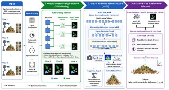
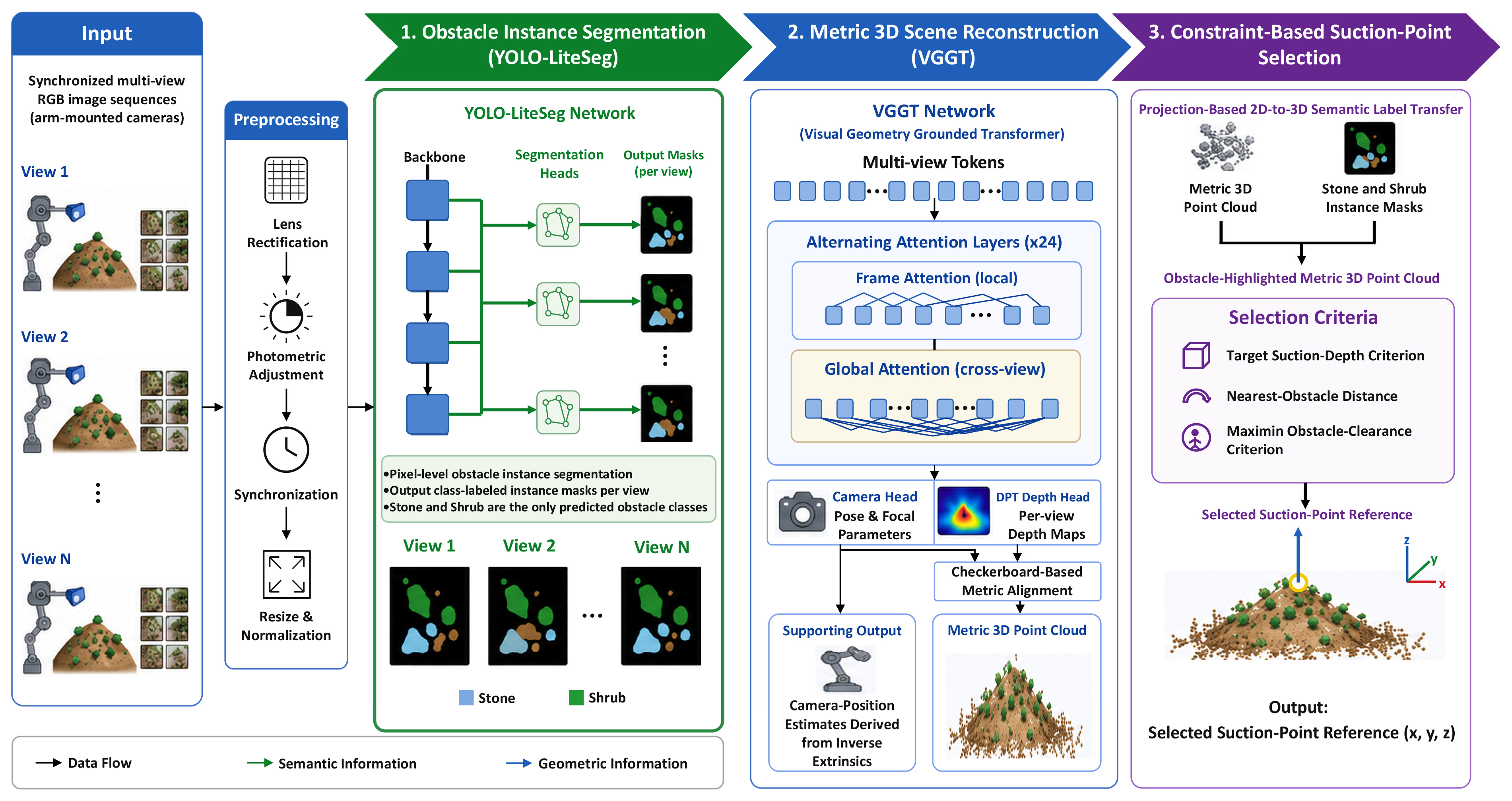
Figure 1 shows the proposed multi-view semantic-geometric perception workflow for post-disaster flexible suction operations. The framework takes synchronized RGB image sequences acquired from multiple arm-mounted camera positions as input and comprises three coupled modules: lightweight obstacle instance segmentation, metric 3D scene reconstruction, and constraint-based suction-point selection. YOLO-LiteSeg generates class-labeled 2D instance masks that provide semantic cues for subsequent projection-based 2D-to-3D semantic label transfer, while VGGT independently predicts camera parameters and dense depth from the RGB images for multi-view reconstruction, followed by metric alignment of the reconstructed scene. Camera-position estimates derived from the recovered extrinsics are retained as supporting outputs. Finally, semantic labels from the 2D obstacle instance masks are transferred to the corresponding reconstructed 3D points, and the resulting metric 3D scene representation integrating obstacle semantics and reconstructed geometry is converted into a suction-point reference using the target suction-depth criterion and the maximin obstacle-clearance criterion. This processing chain converts synchronized multi-view RGB images into metrically interpretable spatial information for suction-point selection.
Figure 1.
Workflow of the proposed multi-view semantic-geometric perception framework for post-disaster flexible suction operations. In the Preprocessing block, lens rectification corrects lens distortion, while photometric adjustment helps reduce brightness differences between views. Synchronization aligns frames from different cameras based on their timestamps. Resizing and normalization adapt the RGB frames to model input requirements.
2.2. Obstacle Instance Segmentation Module
2.2.1. Overall Network Architecture
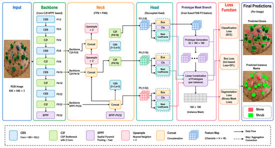
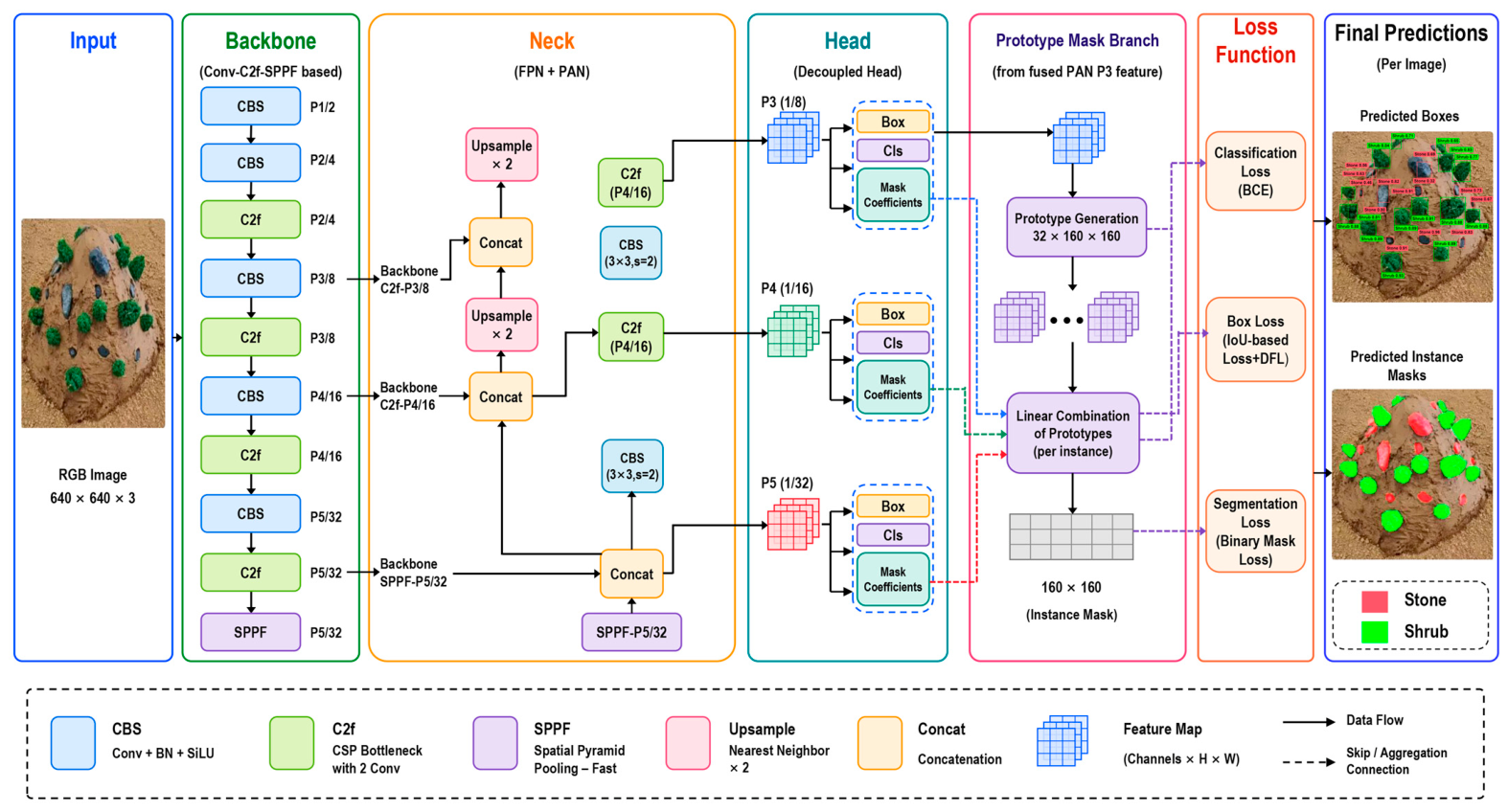
The obstacle instance segmentation module predicts class labels, bounding boxes, and pixel-level masks for individual stones and shrubs in each RGB frame. These class-labeled 2D instance masks provide semantic cues for subsequent projection-based 2D-to-3D semantic label transfer to the reconstructed metric point cloud, yielding obstacle-highlighted metric 3D point clouds for downstream constraint-based suction-point selection. YOLO-LiteSeg is built on YOLOv8m-seg [27] and retains the Backbone-Neck-Head structure. The backbone extracts multi-scale features. The Feature Pyramid Network–Path Aggregation Network (FPN–PAN) neck fuses shallow spatial details with deep semantic information, and the head predicts class labels, bounding boxes, and instance masks. The segmentation head follows the prototype-mask and mask-coefficient mechanism of YOLOv8m-seg [27]; pixel-level instance masks are produced by a linear combination of mask prototypes and instance coefficients. To limit the computational burden of the overall multi-view perception framework, obstacle instance segmentation must operate alongside multi-view 3D reconstruction and subsequent semantic label transfer. A large front-end segmentation model would increase computational load and delay downstream processing. Related lightweight real-time segmentation studies likewise emphasize balancing segmentation accuracy with computational efficiency [28,29,30]. We therefore compressed the backbone and neck by statically scaling channel width, block repetition, and feature-fusion size, while preserving the original mask-prototype prediction mechanism. MGD-based feature-map distillation was used during training to help recover broader spatial structure and fine boundary information that may be weakened during lightweight compression, without adding inference cost. The resulting YOLO-LiteSeg model outputs class labels, bounding boxes, and pixel-level instance masks with fewer parameters, lower computation, and shorter inference time, providing lightweight 2D semantic cues for subsequent projection-based 2D-to-3D semantic label transfer while reducing the computational burden of the overall perception framework. The resulting YOLO-LiteSeg architecture is shown in Figure 2.
Figure 2.
YOLO-LiteSeg network architecture.
2.2.2. Lightweight Improvement Strategy
YOLO-LiteSeg was optimized for two related problems: model compression and performance recovery [31,32,33]. We used static structural scaling and MGD-based feature-map distillation to reduce model complexity while preserving obstacle instance-segmentation performance.
(1) Static structural scaling
We adopted a channel-compression strategy based on structural scaling [33,34,35]. A width factor and a depth factor constrain convolutional channel numbers and layer repeat numbers in the backbone and neck. The scaled channel number and layer number are defined in Equations (1) and (2), respectively:
In Equations (1) and (2), the baseline terms denote the original channel number and repeat number of the model. The channel number is then rounded to a multiple of 8 for hardware-compatible channel scaling [27]. Related lightweight network designs similarly reduce computational complexity through compact bottleneck representations [36]. In this study, the hierarchical adjustment reduces channel and layer complexity across the backbone and neck, thereby lowering parameter count and computation without an additional iterative pruning process [37].
(2) MGD-based feature-map distillation
To offset the loss of feature representation caused by lightweight compression, we introduced a teacher–student feature-map distillation mechanism based on masked generative distillation (MGD) [38]. A pretrained YOLOv8m-seg model was used as the teacher, and YOLO-LiteSeg was the student. During training, student feature maps were randomly masked and reconstructed under the constraint of the teacher feature space [38]. This training strategy was intended to encourage the student to learn feature distributions from the teacher and recover feature representation weakened by lightweight compression. The distillation loss minimizes the squared L2 distance between the reconstructed student feature map and the corresponding teacher feature map. The distillation loss is calculated in Equation (3):
In Equation (3), the terms denote the teacher and student feature maps at the selected layer, the random binary mask matrix, element-wise multiplication, the feature-generation module composed of consecutive convolutional layers, and the total number of feature pixels used in the calculation. The subscript 2 denotes the L2 norm, while the superscript 2 indicates that the norm is squared.
The total loss combines the distillation term with the original task loss, as given in Equation (4):
In Equation (4), the coefficient controls distillation strength. This masked reconstruction mechanism adds no inference cost. Feature-level knowledge transfer has been used to convey intermediate representations from teacher to student networks [39,40]. In this study, the masked reconstruction mechanism is intended to help the compressed student recover broader spatial structure and fine boundary information that may be weakened during lightweight compression; its effect is evaluated experimentally in Section 4.2.1.
2.3. Metric 3D Scene Reconstruction Module
2.3.1. VGGT-Based Multi-View Reconstruction and Camera-Parameter Recovery
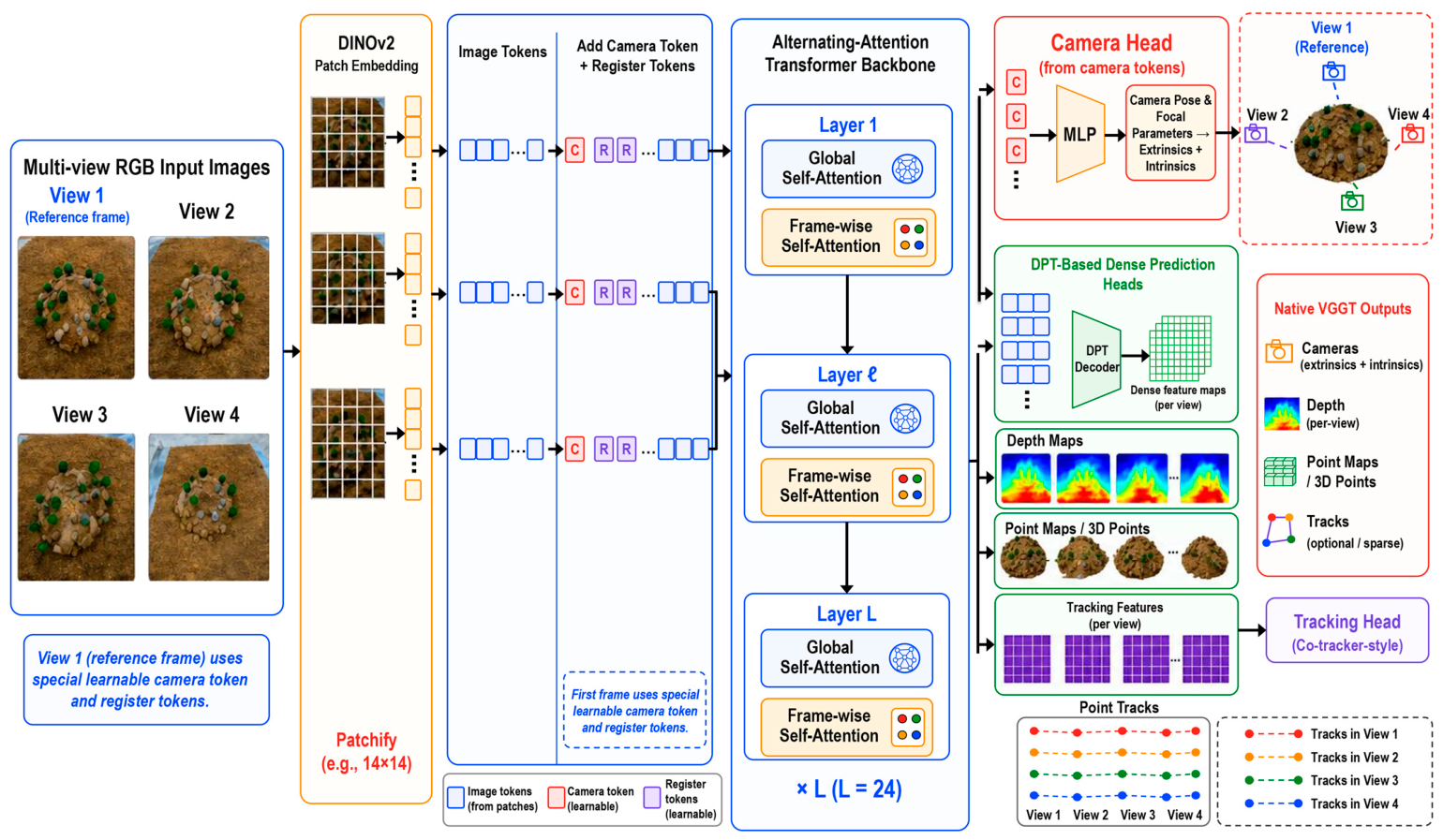
This module uses VGGT [26] to recover scene geometry and camera parameters from selected synchronized multi-view RGB frames. Only RGB images are used as perception inputs; no measured depth stream is provided to VGGT. For each group of multi-view observations, VGGT jointly estimates dense depth maps together with camera intrinsics and extrinsics, providing the geometric information required for subsequent 3D scene reconstruction and spatial alignment. The VGGT-predicted depth maps and camera parameters are used to reconstruct an initial scene point cloud, which is further transformed to metric scale through the checkerboard-based metric alignment procedure described in Section 2.3.2. The recovered camera extrinsics are also retained to obtain supporting arm-mounted camera-position estimates in the common workspace coordinate system. Related studies on multi-view stereo, camera-pose estimation, stereo matching, and depth learning provide complementary context for these geometric estimation tasks [41,42,43,44]. Figure 3 summarizes the VGGT-based reconstruction process used in this study.
Figure 3.
VGGT architecture with camera parameters and depth outputs used in the proposed framework.
The synchronized RGB images are first encoded by the DINOv2 [45] image encoder to generate image tokens, which are combined with learnable camera and register tokens before entering the VGGT backbone. The 24-layer transformer backbone alternates frame-wise and global self-attention. Frame-wise attention preserves appearance and structural information within each view, whereas global attention exchanges information across views to establish cross-view geometric consistency. Through repeated alternation of these two attention operations, the network integrates local image evidence with multi-view correspondences and produces a shared representation for camera and dense-geometry prediction.
Two outputs of VGGT are used in the proposed framework. Although the native VGGT architecture also includes point-map and tracking-related outputs, these branches are not used for downstream processing in this study. The camera head predicts camera pose and focal parameters, which are converted into camera extrinsic and intrinsic matrices, while the Dense Prediction Transformer (DPT) [46] head generates the corresponding dense depth maps from the RGB inputs. The predicted depth values are back-projected using the recovered camera parameters to obtain 3D points from the individual views, which are then combined to form the initial reconstructed scene point cloud. This point cloud provides the geometric basis for metric alignment and subsequent projection-based 2D-to-3D semantic label transfer. In parallel, the recovered world-to-camera extrinsics are inverted to obtain the camera centers used as supporting camera-position estimates, rather than treating the extrinsic translation vectors as camera positions.
For camera-position evaluation, the camera centers derived from the inverse extrinsic transforms are mapped into the common workspace coordinate system and projected onto the longitudinal–vertical plane defined by the manipulator working direction and vertical axis. The projected positions are compared with the measured installation positions to quantify the spatial consistency of the recovered camera-position estimates. These position estimates are used as supplementary evidence of the multi-view reconstruction quality, whereas the primary output of this module remains the reconstructed 3D scene geometry.
2.3.2. Metric Alignment and Projection-Based 2D-to-3D Semantic Label Transfer
Metric alignment was performed using checkerboard-based scale calibration. The reconstructed scene point cloud was scaled and transformed into the common workspace coordinate system before semantic label transfer. For each image view, the reconstructed 3D points were projected into the corresponding image plane using the recovered camera parameters and associated with the 2D instance masks. Semantic labels from the Stone and Shrub instance masks were then transferred to the corresponding reconstructed 3D points, yielding obstacle-highlighted metric 3D point clouds. Related projection-based approaches have transferred image-level semantic information to corresponding 3D points [6]. In the proposed framework, this projection-based 2D-to-3D semantic label transfer produces a metric 3D scene representation integrating obstacle semantics and reconstructed geometry for downstream constraint-based suction-point selection.
2.4. Constraint-Based Suction-Point Selection
The constraint-based suction-point selection module uses the obstacle-highlighted metric 3D point cloud generated by the preceding semantic label transfer stage as its basic input. In this study, a suction point refers to a 3D operating location on the reconstructed sludge region where the suction head is intended to be positioned. Candidate eligibility is determined according to the target suction-depth criterion and the spatial clearance from obstacle-highlighted points. Based on preliminary suction experiments, the target suction depth was set to approximately 20 cm, at which relatively favorable suction performance had been observed. Candidate points were generated in sludge regions satisfying this target suction-depth criterion. For each candidate point, the nearest-obstacle distance was calculated from the Euclidean distance to the obstacle-highlighted Stone and Shrub point sets. The selected suction-point reference was defined as the candidate that maximized the minimum Euclidean distance to all obstacle-highlighted points. The suction-point reference is therefore selected according to the maximin obstacle-clearance criterion within the predefined candidate set, rather than as an absolute optimum for the full suction operation process. In this way, the module converts the metric 3D scene representation integrating obstacle semantics and reconstructed geometry into a reproducible, constraint-based spatial reference for flexible suction rather than a global optimum for the complete manipulation trajectory.
3. Experimental Protocol and Dataset
3.1. Experimental Setup
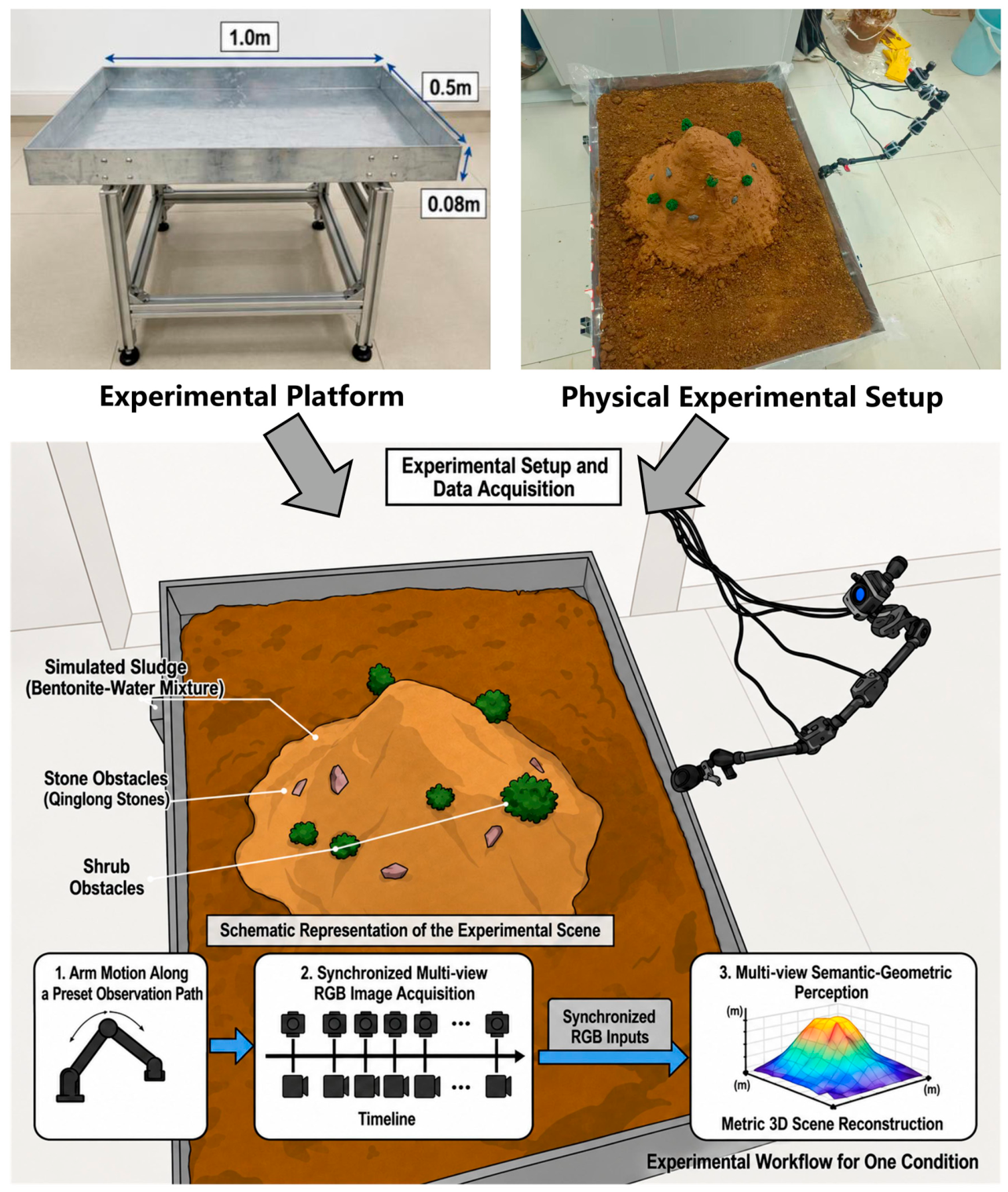
To evaluate the proposed multi-view semantic-geometric perception framework under controlled conditions, we built a laboratory platform representing the near-field workspace of post-disaster flexible suction. The platform reproduces a simulated post-disaster sludge workspace containing stones and shrubs as representative obstacles. The dataset consists of multi-view RGB image sequences acquired by RGB-D cameras mounted on a small multi-link arm configured to emulate the observation setup of an emergency excavator. These cameras were used for image acquisition, but only their RGB streams were used as perception inputs; the depth streams were not used as model inputs. The rectangular steel platform measured 1 m × 0.5 m × 0.08 m. A three-link arm system was fixed to one side. Bentonite mixed with water was used to simulate sludge. Qinglong stones and biomimetic shrubs were used to simulate stone and shrub obstacles and were arranged according to the required obstacle coverage level and size. During data collection, the multi-link arm moved along a preset observation path. The arm-mounted cameras synchronously collected continuous RGB image sequences. This process represents a pre-operation visual inspection stage in which multi-view observations of sludge deposits and obstacles are acquired before flexible suction. Figure 4 shows the platform structure.
Figure 4.
Experimental platform and data-acquisition setup for simulated post-disaster flexible suction operations.
3.2. Experimental Conditions
The experiment varied four factors: sludge-deposit thickness, camera configuration, Stone projected-area coverage ratio, and Shrub projected-area coverage ratio to evaluate the robustness of the multi-view semantic-geometric perception framework under controlled visual and geometric variations. Table 1 summarizes the working conditions, data collection, and dataset partitioning. Sludge-deposit thickness was predefined at three levels—shallow (15 cm), medium (25 cm), and deep (35 cm)—to represent controlled variations in deposit thickness. Camera configuration was set by field-of-view coverage and redundancy: the basic configuration used one end-mounted camera observation position, the enhanced configuration used three camera observation positions, and the redundant configuration used five camera observation positions. Stone and Shrub projected-area coverage ratios were used to characterize class-specific image-plane obstacle occupancy and visual interference in perception. For both Stone and Shrub obstacles, low, medium, and high projected-area coverage levels corresponded to projected coverage ratios below 10%, 10–25%, and above 25%, respectively. An L9(34) orthogonal array was used to generate nine controlled working conditions, C1–C9.
Table 1.
Experimental conditions and dataset configuration.
3.3. Dataset Construction and Implementation Details
The dataset comprised nine controlled experimental conditions covering four factors: sludge-deposit thickness, camera configuration, Stone projected-area coverage ratio, and Shrub projected-area coverage ratio. The raw data were synchronized RGB image sequences acquired by arm-mounted cameras. Before model input, the multi-view RGB frames underwent lens rectification, basic photometric adjustment, timestamp-based inter-view synchronization, resizing, and normalization. Image quality screening and checkerboard-based scale calibration were additionally performed for dataset preparation and metric reconstruction. Random cropping and color jittering were applied only to the training subset for data augmentation. Pixel-level instance masks were annotated with LabelMe [47] and labeled as Stone or Shrub. Ground-truth physical parameters were obtained by container filling for volume, grid-based caliper measurements for thickness, and preset arrangement and manual measurement for the Stone and Shrub projected-area coverage ratios and spatial positions. In total, 2098 YOLO image samples with pixel-level instance annotations were obtained. Because the raw data were continuous RGB image sequences, the annotated samples were divided using a sequence-block strategy instead of random frame-level splitting. For each working condition, frames were first ordered by timestamp. Temporal buffer intervals of 10 frames were removed between the training and validation blocks and between the validation and test blocks to reduce near-duplicate frame leakage. After removing these buffer frames, 1918 annotated samples were retained from the original 2098 images, including 1531 training images, 187 validation images, and 200 test images. These samples were used for YOLO-LiteSeg training, model selection, and final performance evaluation. To reduce continuous-frame redundancy and keep 3D reconstruction computation manageable, about 180 representative multi-view images were extracted from the retained non-buffer image pool of each condition as VGGT inputs. Each condition retained 172–190 images, giving 1628 selected RGB images used as VGGT reconstruction inputs. These images were used for metric 3D scene reconstruction, camera-parameter recovery and supporting camera-position evaluation, sludge-volume estimation and height-profile-based reconstruction evaluation, and constraint-based suction-point selection analysis.
The experiments were conducted on a Windows 11 workstation. The CPU was an AMD Ryzen 9 9950X 16-Core Processor, and the GPU was an NVIDIA GeForce RTX 5060 Ti. The programming environment was Python 3.11.14, CUDA 12.8, and PyTorch 2.9.1.
Generative AI was used only to assist in preparing the lower schematic illustration in Figure 4; it was not used to generate or modify experimental data, data-derived graphics, quantitative results, analyses, or conclusions.
4. Results and Discussion
4.1. Evaluation Metrics and Spatial Measures
The proposed multi-view semantic-geometric perception framework is evaluated at three output levels: image-level obstacle semantics, metric 3D scene reconstruction, and spatial outputs for suction-point selection in controlled post-disaster flexible suction scenes. Its outputs include 2D Stone and Shrub masks, obstacle-highlighted metric 3D point clouds, supporting arm-mounted camera-position estimates, suction-point references under the predefined suction-depth and obstacle-clearance criteria, and sludge-deposit height profiles.
To evaluate these outputs, the measures were organized into two levels with reference to the classification performance measures discussed by Sokolova et al. [48] and the metrics commonly used in YOLO-series evaluation [49]. Image-level obstacle instance-segmentation performance is measured using Precision, Recall [48], and mean average precision (mAP) [50], together with the efficiency measures reported in Section 4.2.1. Semantic and geometric evaluation measures quantify the metric quality and spatial consistency of the reconstructed metric 3D scene representation through height-profile accuracy, volume consistency, projected camera-position error, and the spatial relationship between suction-point references and obstacle-highlighted points. The relevant formulas are given in Equations (5)–(12):
(1) Height-profile-based evaluation of metric 3D reconstruction:
Because the working surface is uneven, the ground reference plane is first fitted with random sample consensus (RANSAC) [51]. In this study, sludge-deposit thickness is defined as the maximum vertical distance from the sludge surface to the fitted ground reference plane, corresponding to the mound peak height. The recovered vertical heights are used as physical measures for evaluating the metric accuracy of the reconstructed sludge geometry. In the camera coordinate system, with the Z-axis defined as positive downward, the relative vertical height of any sludge-surface point and the mound peak height are calculated using Equations (5) and (6), respectively:
(2) Volume estimation of the 3D point cloud:
The Quickhull algorithm [52] generates the minimum convex polyhedron enclosing the sludge point cloud [53]. The polyhedron is decomposed into tetrahedra that share the coordinate origin as a common vertex. The reconstructed volume is calculated by Equation (7) [54]:
where the three terms denote the vertex vectors of the i-th triangular facet on the convex hull surface, with the coordinate origin used as the reference.
(3) Projected arm-mounted camera-position error:
VGGT provides camera extrinsics in a world-to-camera form, in which the rotation matrix R and translation vector t map a reconstructed scene point from the scene coordinate system into the camera coordinate system [26]. Accordingly, the translation vector t is not used directly as the camera position. The extrinsic matrix, camera intrinsic matrix, and perspective projection from a 3D scene point to the image plane are expressed in Equations (8)–(10) [55].
In Equations (8)–(10), R and t denote the world-to-camera rotation matrix and translation vector, respectively, and λ denotes the projective depth scale. Because t is not the camera position in the reconstructed scene coordinate system, the camera center Cw is recovered by inverting the rigid extrinsic transform as:
(4) Suction-point selection:
Within the sludge candidate point set satisfying the target suction-depth criterion, the system applies a maximin obstacle-clearance criterion [56]. Let denote the sludge candidate point set and the identified obstacle point set. The suction-point reference is defined as the candidate that maximizes the Euclidean distance to its nearest obstacle, as given in Equation (12):
Here, denotes the L2 norm, and represents the Euclidean distance between the candidate point and an obstacle point.
4.2. Obstacle Instance Segmentation Performance of YOLO-LiteSeg
4.2.1. Ablation Analysis of YOLO-LiteSeg
YOLO-LiteSeg was derived from YOLOv8m-seg through static structural scaling and MGD-based feature-map distillation. Table 2 compares the baseline, scaled student, and final model in segmentation accuracy and computational efficiency.
Table 2.
Ablation results of YOLO-LiteSeg derived from YOLOv8m-seg.
Static structural scaling reduced parameters from 27.24 M to 2.61 M, giga floating-point operations (GFLOPs) from 52.37 to 5.47, model size from 52.28 MB to 5.19 MB, and inference time from 12.30 ms to 4.50 ms. The compression reduced mAP50–95 from 94.10% to 74.52%, indicating loss of fine mask detail.
MGD-based distillation preserved the 2.61 M parameters and 5.47 GFLOPs, while producing 99.02% mAP50, 84.36% mAP50–95, and 4.56 ms inference. It therefore recovered part of the compression-induced accuracy loss with negligible inference overhead.
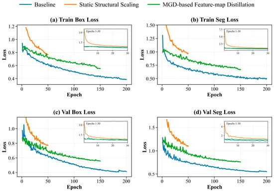
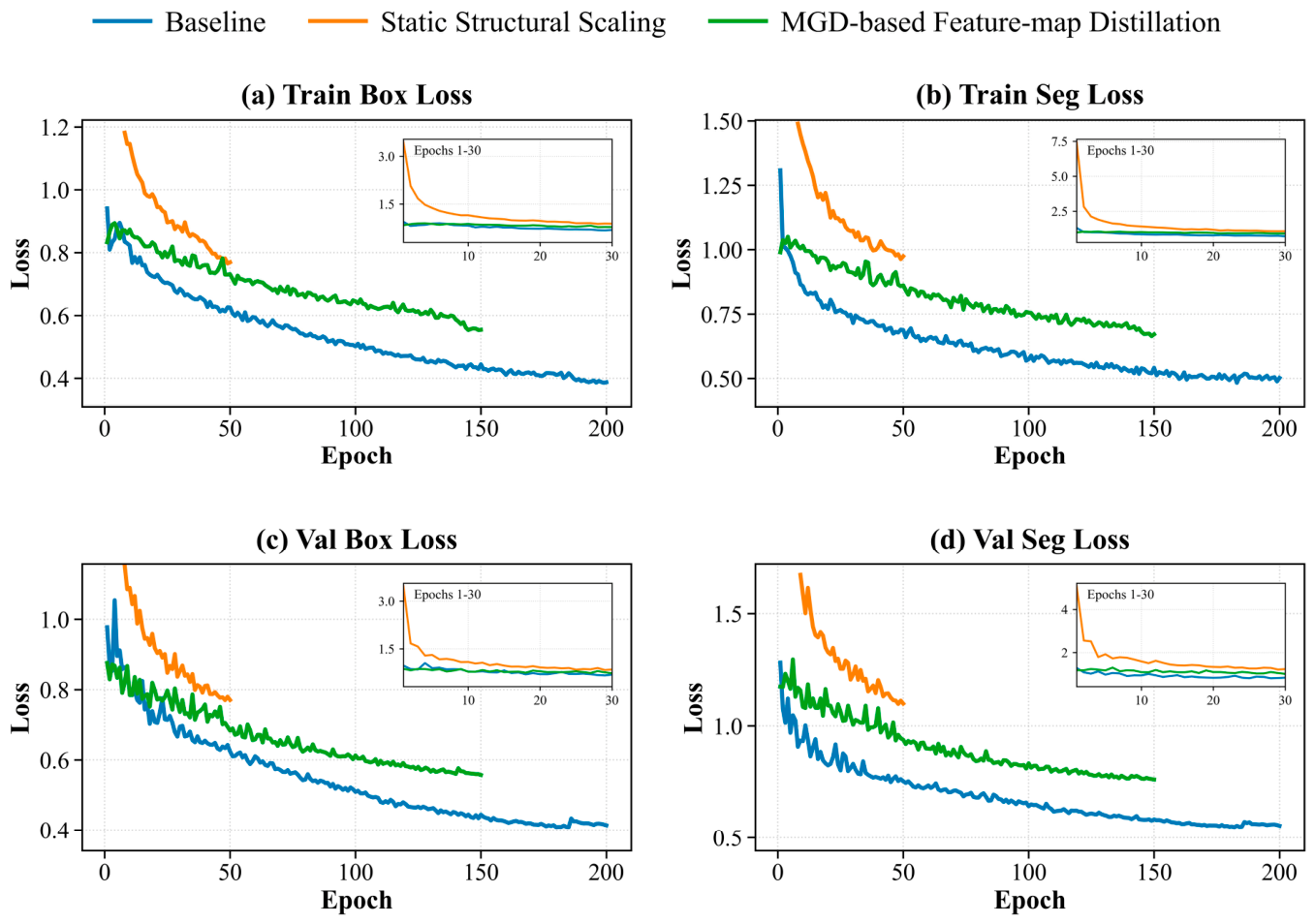
Figure 5 further supports the ablation results. Under the adopted training procedure, early stopping was determined by the monitored validation performance: training was terminated when no further meaningful validation improvement was obtained, and the best-performing checkpoint was retained. The YOLOv8m-seg baseline completed about 200 epochs, by which both the training and validation losses had stabilized, with Train Box Loss and Train Seg Loss values of 0.39 and 0.49. The scaled student stopped at about 50 epochs because its validation performance ceased to improve; continued training therefore provided no additional validation-performance benefit. However, it retained higher training losses of 0.77 and 0.97, reflecting the reduced optimization capacity caused by strong compression. After MGD-based distillation, YOLO-LiteSeg continued improving until about 150 epochs and stopped after the validation gain had saturated, reducing the corresponding training losses to 0.55 and 0.67. The validation curves showed the same trend: Val Box Loss and Val Seg Loss were 0.42 and 0.56 for the baseline, 0.77 and 1.10 for the scaled student, and 0.56 and 0.76 for YOLO-LiteSeg. These results indicate that MGD partially recovered the optimization capacity and validation performance degraded by structural compression.
Figure 5.
Training and validation curves of the YOLOv8m-seg baseline, scaled student model, and YOLO-LiteSeg during the ablation process.
4.2.2. Obstacle Instance Segmentation Performance Under Different Working Conditions
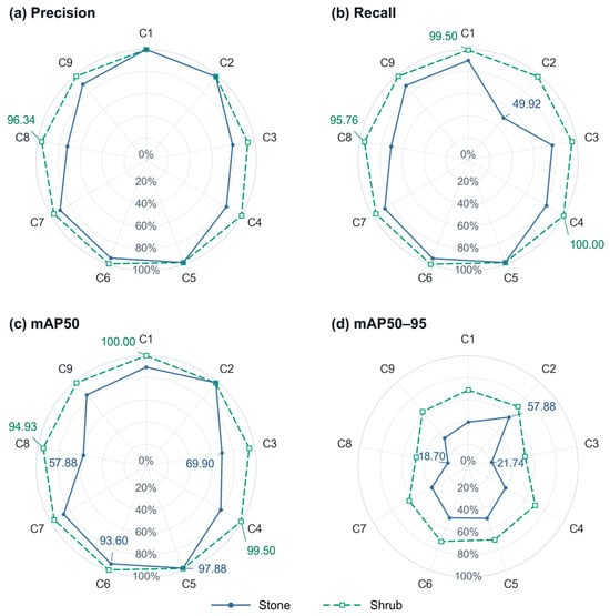
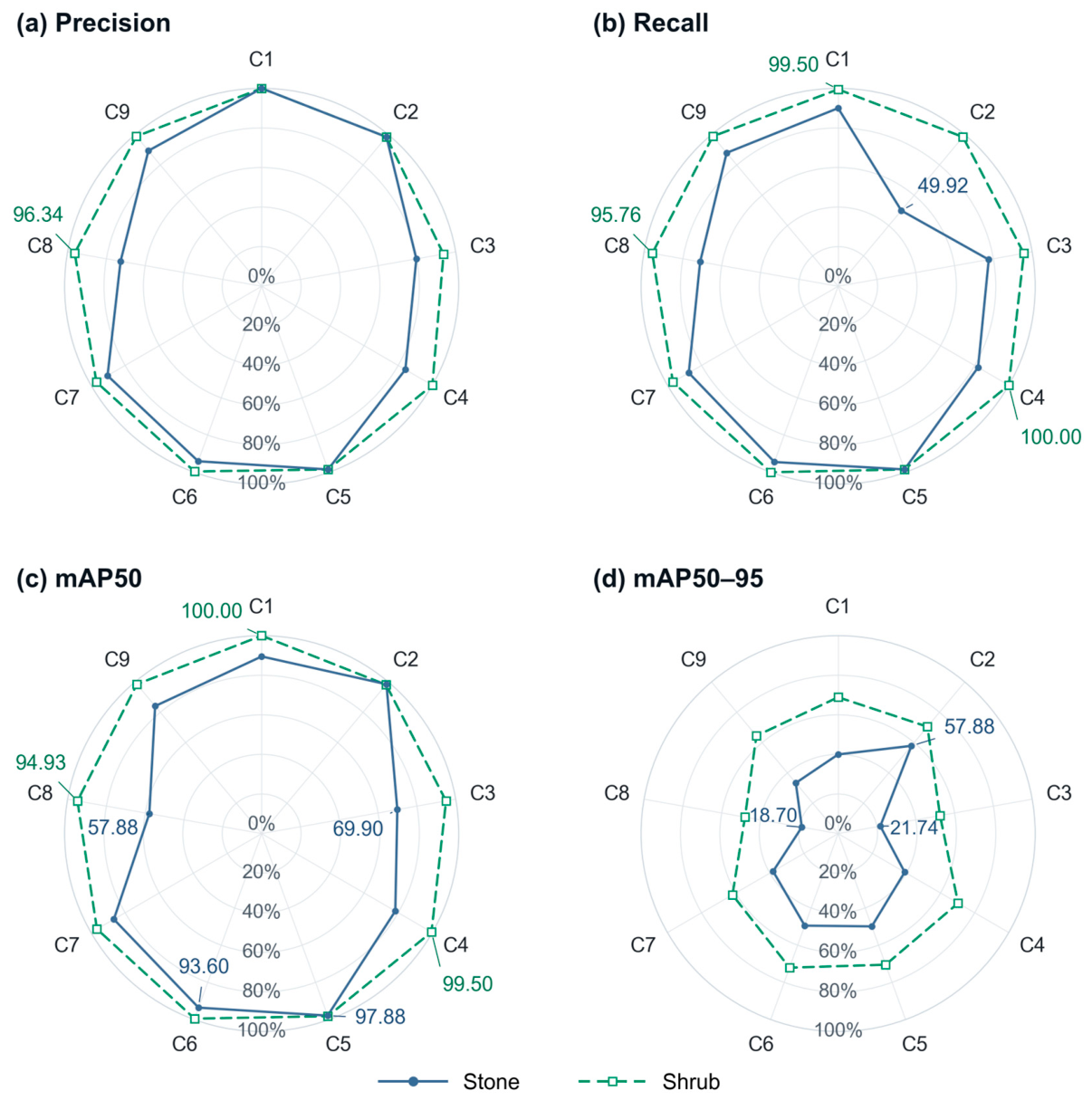
To evaluate YOLO-LiteSeg performance across controlled conditions, Precision, Recall, mAP50, and mAP50–95 values were calculated for Stone and Shrub under C1–C9, as shown in Figure 6. Overall, Shrub showed higher stability than Stone. In C1, C4, and C6, Shrub Recall reached 99.50%, 100.00%, and 100.00%, respectively, and Shrub mAP50 reached 100.00%, 99.50%, and 99.50%, respectively. Even in the more complex C8 condition, Shrub achieved 96.34% Precision, 95.76% Recall, and 94.93% mAP50. This likely reflects the clearer color, shape, and boundary contrast of simulated shrubs against the sludge background.
Figure 6.
Comparison of YOLO-LiteSeg segmentation performance for Stone and Shrub under nine working conditions (C1–C9): (a) Precision; (b) Recall; (c) mAP50; and (d) mAP50–95. All values are expressed as percentages.
Stone segmentation was more sensitive to changes in working conditions. Stone mAP50 reached 97.88% in C5 and 93.60% in C6 but decreased to 69.90% in C3 and 57.88% in C8. In C2, Stone Recall was only 49.92%, while Stone mAP50–95 was 57.88%. The low Recall suggests that some Stone instances were missed, while mAP50–95 reflects overall segmentation performance across multiple IoU thresholds. Stone mAP50–95 values in C3 and C8 were only 21.74% and 18.70%, respectively. These lower values may reflect reduced mask quality under partial burial, occlusion, and texture similarity between stones and sludge. To improve mask quality under these conditions, future training could include more occluded and partially buried Stone samples and carefully verified instance-mask annotations. Broader variation in training viewpoints and lighting, together with tuning the MGD distillation coefficient λ, could also improve segmentation performance across C1–C9.
Overall, YOLO-LiteSeg provided class-labeled 2D instance masks as semantic cues for subsequent projection-based 2D-to-3D semantic label transfer and obstacle-highlighted metric 3D point-cloud generation. The main source of segmentation fluctuation was the Stone class under occlusion and texture similarity between stones and sludge, highlighting the importance of interpreting image-level obstacle masks together with reconstructed geometry in downstream spatial analysis.
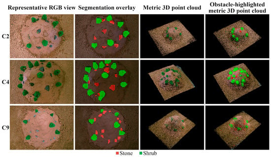
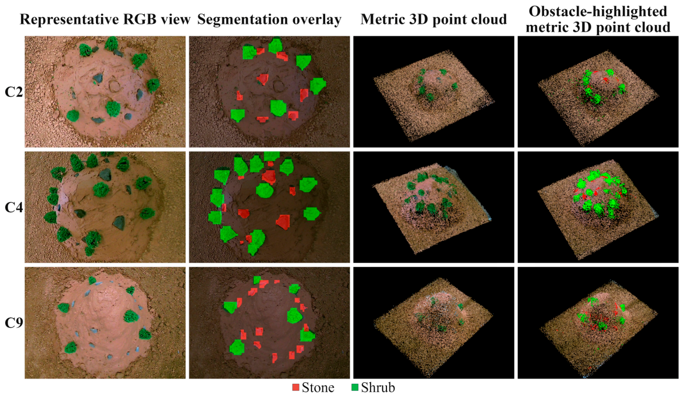
To verify the projection-based 2D-to-3D semantic label transfer stage, C2, C4, and C9 were selected as representative shallow, medium, and deep conditions. As shown in Figure 7, Stone and Shrub labels from the 2D instance masks were transferred to the corresponding reconstructed points, producing obstacle-highlighted metric 3D point clouds with clear spatial correspondence. These representative visualizations qualitatively show that image-level obstacle semantics can be associated with reconstructed geometry for 3D obstacle localization and spatial reasoning for suction-point selection.
Figure 7.
Projection-based 2D-to-3D semantic label transfer and obstacle-highlighted metric 3D point clouds under representative working conditions.
4.3. Evaluation of Metric 3D Reconstruction and Spatial Outputs
4.3.1. Metric 3D Scene Reconstruction Accuracy for Sludge Deposits
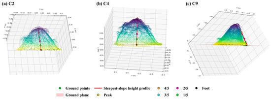
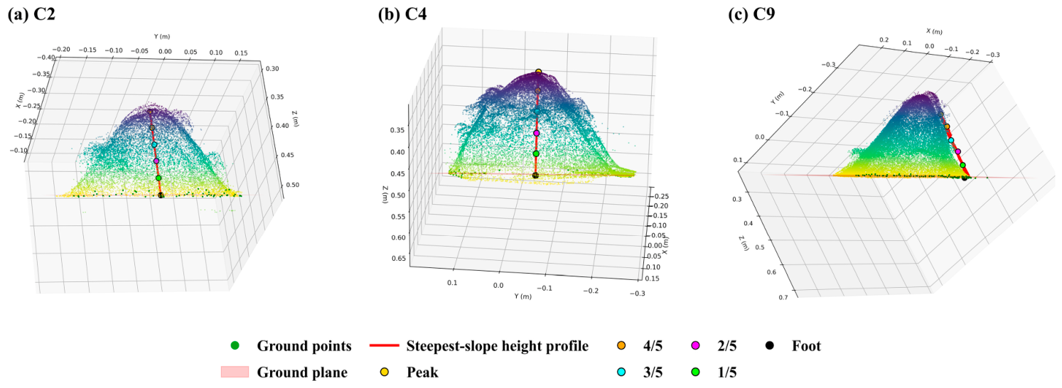
Metric 3D scene reconstruction accuracy was evaluated primarily through steepest-slope height-profile recovery, with volume consistency as a supporting metric. After RANSAC ground-plane fitting, the highest point was defined as the Peak, and the direction of maximum local height decrease defined the steepest slope. This direction was selected because it spans the largest vertical variation from the mound peak toward the slope foot, thereby providing a larger vertical dynamic range for evaluating metric-scale deviations than a flatter profile. As illustrated in Figure 8, five normalized positions—Peak, 4/5, 3/5, 2/5, and 1/5—were sampled along this profile. Multi-point sampling evaluates not only peak-height recovery but also the continuity and shape of the reconstructed slope, while enabling consistent comparison across sludge deposits with different thicknesses and surface forms. The corresponding multi-point height-profile recovery results are summarized in Table 3.
Figure 8.
Extraction of the steepest-slope height profile and multi-point sampling under representative working conditions.
Table 3.
Multi-point height-profile recovery along the steepest slope under different conditions.
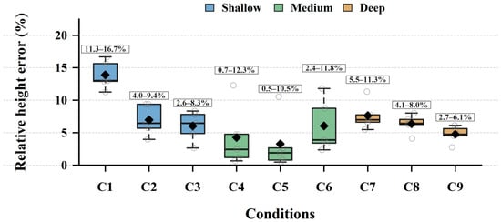
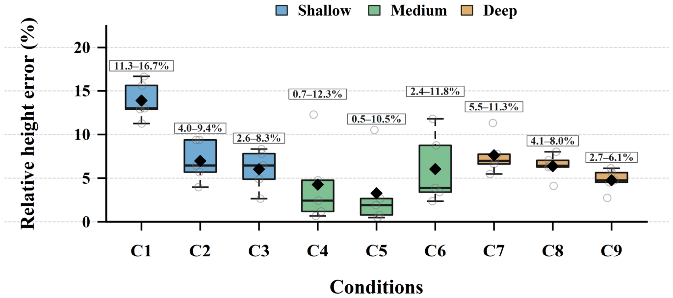
Table 3 and Figure 9 show that the mean absolute error (MAE) of height-profile recovery remained below 2 cm in all nine conditions. Representative errors were 0.60, 0.50, 0.42, 0.30, and 1.00 cm for C2–C6, respectively. The Foot point served only as the zero-height reference. These results support the metric consistency of the reconstructed height profiles when the slope point cloud is continuous and contains sufficient geometric or textural cues.
Figure 9.
Relative-error distribution of steepest-slope height-profile recovery under different working conditions.
Condition-wise relative errors further illustrate the differences associated with scene geometry and camera configuration. In the shallow group, C2 and C3 produced mean relative errors of 6.97% and 6.02%, lower than the 13.89% of C1, where limited geometric and textural cues were associated with systematic underestimation. In the medium-depth group, C4–C6 achieved 4.26%, 3.27%, and 6.04%, respectively. Although C6 used a redundant configuration, local overestimation remained at the 3/5 and 2/5 positions, indicating that additional views do not eliminate errors caused by point-cloud anomalies or profile-sampling offsets. In the deep group, C7–C9 yielded 7.63%, 6.37%, and 4.76%, with C9 performing best. Within these controlled conditions, configurations with greater camera redundancy were generally associated with more stable reconstruction results, while accuracy still depended on texture, occlusion, point-cloud continuity, and sampling consistency. The contrast between stable height-profile recovery and the larger volume errors therefore supports using multi-point height-profile recovery as the primary metric and volume estimation as supplementary evidence.
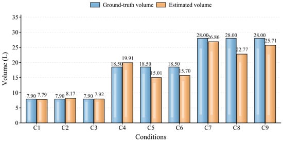
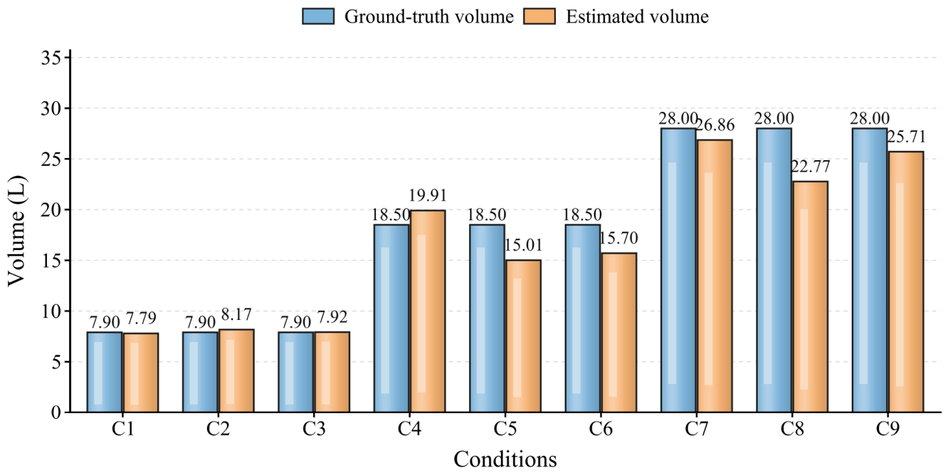
As shown in Figure 10, volume estimates provided an overall scale-consistency check. The shallow conditions C1–C3 closely matched the ground truth, with relative errors of 1.40%, 3.48%, and 0.28%. Errors increased for medium and deep deposits: C5 and C6 produced 15.01 L and 15.70 L compared with the 18.50 L ground truth, while C8 produced 22.77 L compared with 28.00 L, corresponding to an 18.69% error. These underestimations indicate that convex-hull volume integration is more sensitive than profile recovery to incomplete sludge boundaries, local occlusion, and integration-region definition. Volume estimation was therefore retained as a supporting scale-consistency check rather than the primary reconstruction metric.
Figure 10.
Comparison between ground-truth and estimated sludge volumes under different working conditions.
4.3.2. Supporting Evaluation of Arm-Mounted Camera-Position Estimates
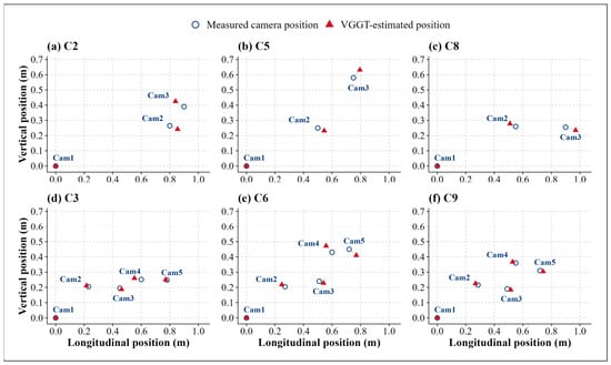
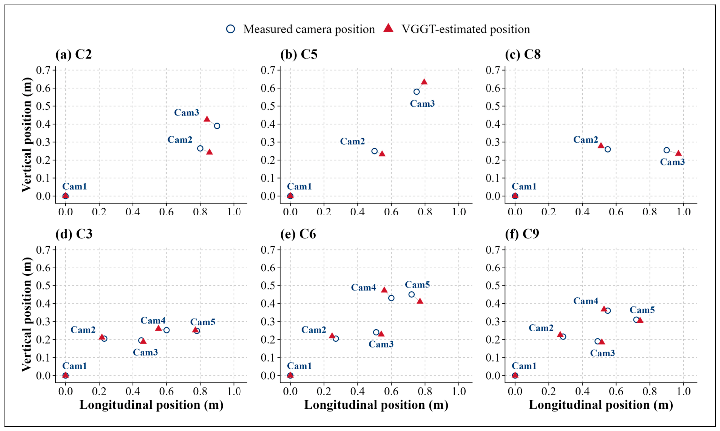
As a supporting evaluation of the multi-view reconstruction module, we compared camera centers derived from the VGGT-predicted extrinsics through the inverse transform with measured installation positions on the longitudinal–vertical projection plane. Figure 11 compares measured installation positions and VGGT-estimated positions projected on the longitudinal–vertical plane for six conditions: C2, C5, C8, C3, C6, and C9. After excluding the fixed reference position Cam1, two and four observation points in the enhanced and redundant configurations, respectively, were included in the projected camera-position error statistics. C1, C4, and C7 used a single end-mounted camera, so they provided too few points for multi-point projected camera-position error statistics. We therefore used them only for scene reconstruction and end-view perception analysis, not for multi-point projected camera-position error statistics. The corresponding projected camera-position errors are summarized in Table 4.
Figure 11.
Projection comparison between measured and estimated arm-mounted camera positions under different working conditions.
Table 4.
Projected arm-mounted camera-position errors under different conditions.
Table 4 shows that VGGT-estimated positions were close to measured positions on the longitudinal–vertical projection plane under the six statistical conditions. After excluding the fixed starting point, the mean longitudinal-position error was 5.98%, and the mean vertical-position error was 5.62%. The 2D Euclidean calculation gave a mean projected camera-position error of 4.02 cm, a projected camera-position root mean square error (RMSE) of 4.53 cm, and a maximum projected camera-position error of 7.28 cm. These values characterize the projected spatial consistency of the camera centers derived from the recovered extrinsics under the tested conditions, rather than demonstrating standalone high-precision localization performance. Under the tested conditions, redundant configurations generally showed lower projected camera-position errors than enhanced configurations. C3 and C9 had mean projected camera-position errors of 2.20 cm and 2.27 cm—lower than C2, C5, and C8, which had errors of 6.45 cm, 5.86 cm, and 5.83 cm. The lower errors observed in C3 and C9 were associated with configurations containing more observation points and stronger multi-view constraints under the tested conditions. C6 was an exception among redundant configurations; its mean projected camera-position error was 4.53 cm, higher than those of C3 and C9. This indicates that the projected camera-position estimates can still be affected by local occlusion, camera spatial distribution, or weaker feature matching along the depth direction. For the end-mounted camera, the errors in C3 and C9 were 0.95 cm and 2.28 cm, much lower than those in C2, C5, C6, and C8. The lower end-camera errors observed in C3 and C9 were also associated with redundant camera configurations, although this trend was not consistent across all conditions. The recovered camera centers therefore serve as supporting spatial information alongside the metric 3D scene representation, rather than as a direct input to semantic label transfer or a standalone localization result.
The arm primarily provides diverse, overlapping viewpoints with sufficient scene coverage, while VGGT estimates camera intrinsics and extrinsics from RGB images, reducing reliance on highly accurate absolute arm positioning. The projected camera-position errors, height-profile mean absolute errors below 2 cm, and visualizations of suction-point references together support using the recovered geometry for suction-point selection under the tested laboratory conditions. Physical suction execution additionally requires a tolerance assessment accounting for suction-head dimensions, obstacle clearance, and reconstruction and control uncertainties.
4.3.3. Visualization of Suction-Point References
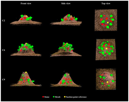
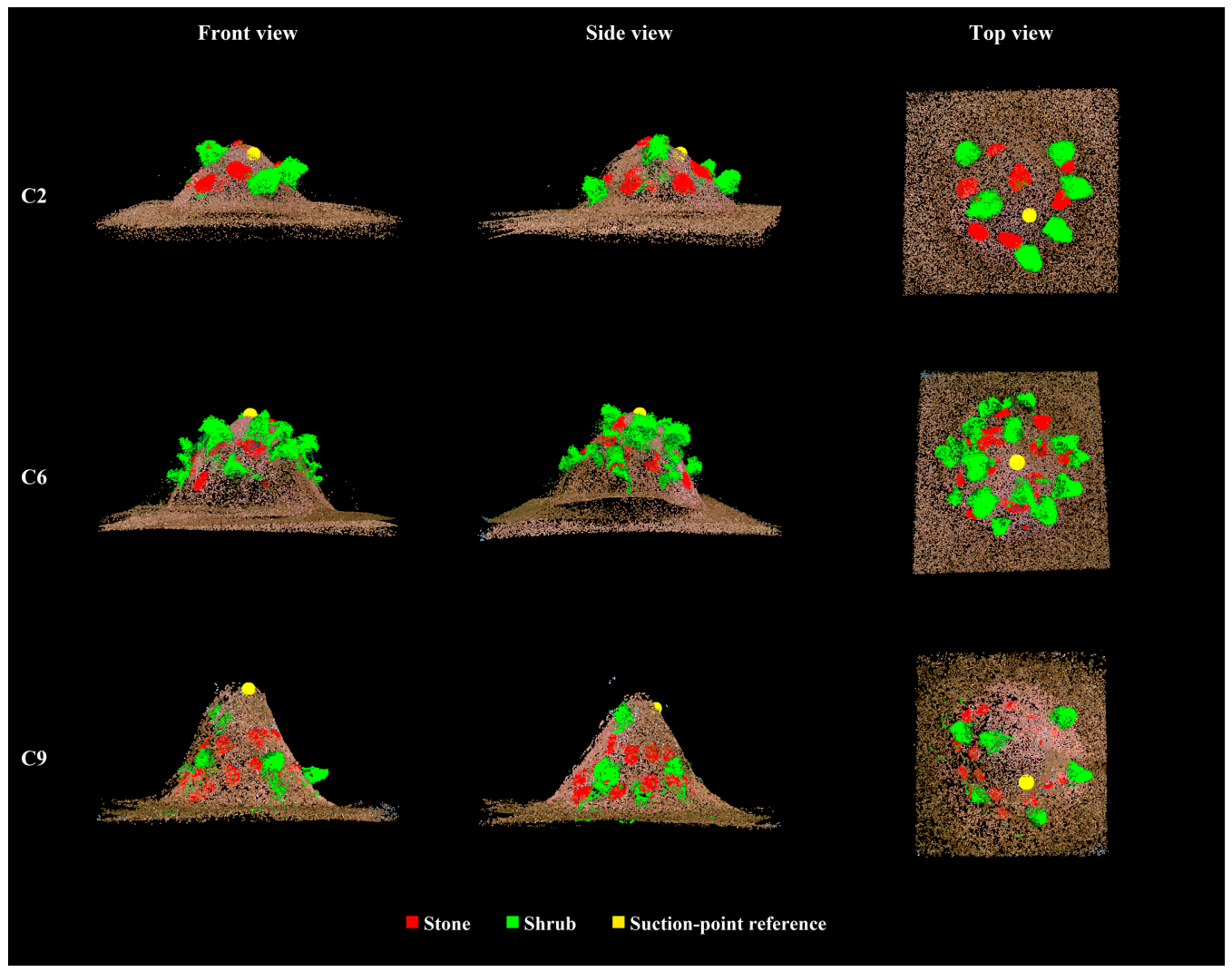
After metric 3D scene reconstruction and projection-based 2D-to-3D semantic label transfer, representative shallow, medium, and deep conditions C2, C6, and C9 were selected for three-view visualization of the suction-point references, as shown in Figure 12. Red, green, and yellow denote Stone points, Shrub points, and the suction-point reference, respectively. In all three conditions, the suction-point reference was located within the sludge candidate region satisfying the target suction-depth criterion. It also maintained a clear spatial relation with the obstacle-highlighted points in the planar view. This result indicates that the metric 3D scene representation integrating reconstructed sludge geometry and obstacle semantics can be converted into a suction-point reference satisfying the predefined suction-depth and obstacle-clearance criteria. The experiments presented here evaluated perception outputs and constraint-based suction-point selection, without subsequent physical suction using the selected references. Future work will include physical suction tests to assess the operational effectiveness of these references.
Figure 12.
Three-view visualization of suction-point references under representative working conditions.
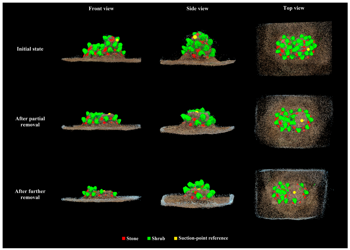
4.4. Suction-Point Selection During Sludge Removal in a Dual-Peak Scene
To supplement the nine controlled working conditions, an additional laboratory scene with a dual-peak sludge geometry and densely arranged Stone and Shrub obstacles was constructed. The redundant camera configuration was used, and RGB image acquisition followed the same procedure as in the original experiments. Sludge was progressively removed from the initially higher peak using a shovel to simulate changes in deposit geometry during suction. The existing perception framework and suction-point selection criteria were retained for this additional case.
Figure 13 provides qualitative visualizations of the obstacle-highlighted metric 3D point clouds and suction-point references at the three stages. After partial removal, the two peaks were approximately equal in height. After further removal, the initially higher peak became lower than the other peak. Changes in deposit geometry and obstacle distribution can alter the candidate region and nearest-obstacle distances, potentially changing the selected suction-point reference.
Figure 13.
Suction-point references at three stages of manual sludge removal in a dual-peak scene. Rows show the initial state and the states after partial and further removal. Columns show front, side, and top views.
5. Conclusions
This study developed a multi-view semantic-geometric perception framework for post-disaster flexible suction using synchronized multi-view RGB images acquired by arm-mounted cameras, linking lightweight obstacle instance segmentation with metric 3D scene reconstruction, projection-based 2D-to-3D semantic label transfer, and constraint-based suction-point selection. The resulting processing chain forms a metric 3D scene representation integrating obstacle semantics and reconstructed geometry. Supporting camera-position estimates were evaluated as an additional output of the multi-view reconstruction module. The framework was evaluated under nine controlled simulated conditions varying sludge-deposit thickness, camera configuration, Stone projected-area coverage ratio, and Shrub projected-area coverage ratio. An additional dual-peak scene was used to qualitatively evaluate suction-point selection at three stages of manual sludge removal.
(1) YOLO-LiteSeg combined static structural scaling with MGD-based feature-map distillation. It reduced parameters from 27.24 M to 2.61 M and GFLOPs from 52.37 to 5.47, while achieving 99.02% mAP50 and 84.36% mAP50–95. Shrub segmentation remained stable, whereas Stone performance declined under partial burial and texture similarity, highlighting the importance of interpreting image-level obstacle masks together with reconstructed geometry in downstream spatial analysis. The resulting class-labeled 2D instance masks provided semantic cues for subsequent projection-based 2D-to-3D semantic label transfer.
(2) Metric 3D scene reconstruction recovered steepest-slope height profiles with mean absolute errors below 2 cm in all nine conditions. Volume estimates supported scale-consistency assessment but were more sensitive to incomplete boundaries, occlusion, and multi-view coverage. Evaluation of the supporting camera-position estimates under enhanced and redundant configurations yielded a mean projected camera-position error of 4.02 cm, an RMSE of 4.53 cm, and a maximum error of 7.28 cm. Under the tested conditions, the recovered camera centers served as supporting spatial information alongside the metric 3D scene representation rather than as a standalone high-precision localization result.
(3) The projection-based 2D-to-3D semantic label transfer stage produced obstacle-highlighted metric 3D point clouds, and applying the target suction-depth and maximin obstacle-clearance criteria yielded suction-point references satisfying the predefined criteria under representative conditions. These outputs provide constraint-based spatial references for suction-point selection under predefined suction-depth and obstacle-clearance criteria, rather than global optima for the complete suction trajectory or process.
Overall, the proposed multi-view semantic-geometric perception framework converts synchronized multi-view RGB images into a metric 3D scene representation that integrates obstacle semantics with reconstructed sludge geometry and provides metrically interpretable spatial information for post-disaster flexible suction under the tested controlled conditions. Its current validation is limited to controlled simulations and criterion-based evaluation with representative visualization of suction-point references; performance in real disaster sites and during actual suction remains unverified. Future work will examine real-site data, online multi-view scene updates, suction-process feedback, and path planning to evaluate generalization and closed-loop deployment.
Author Contributions
Conceptualization, H.W.; methodology, H.W.; software, H.W.; validation, H.W.; formal analysis, H.W.; investigation, H.W.; resources, Y.Y.; data curation, H.W.; writing—original draft preparation, H.W.; writing—review and editing, H.W. and Y.Y.; visualization, H.W.; supervision, Y.Y.; project administration, Y.Y. All authors have read and agreed to the published version of the manuscript.
Funding
This research was supported by the Fujian Provincial Science and Technology Plan Project under the Central Guidance for Local Science and Technology Development Special Fund (Grant No. 2024L3031). The project was undertaken by Fujian Haishan Machinery Co., Ltd., with Fuzhou University participating as a research unit.
Institutional Review Board Statement
Not applicable.
Informed Consent Statement
Not applicable.
Data Availability Statement
The data that support the findings of this study are available from the corresponding author upon reasonable request. The data are not publicly available due to confidentiality and contractual restrictions associated with the collaborative project.
Acknowledgments
During the preparation of this manuscript, the authors used ChatGPT (OpenAI) for language polishing and textual assistance in organizing schematic descriptions, and the image-generation capability of ChatGPT (OpenAI, GPT-5.5) to assist in preparing the lower schematic illustration in Figure 4. All AI-assisted outputs were reviewed, edited, and verified by the authors for accuracy and conceptual consistency with the experimental setup. All experimental data, data-derived graphics, quantitative results, analyses, and conclusions were produced, checked, and finalized by the authors. The authors take full responsibility for the content of the manuscript.
Conflicts of Interest
The authors declare no conflicts of interest. Fujian Haishan Machinery Co., Ltd., the lead organization of the government-funded project described in the Funding statement, neither funded nor participated in the research reported in this article. The government funding agency had no role in the study design; data collection, analysis, or interpretation; manuscript preparation; or the decision to publish.
References
- Wang, X.; Mao, H. Spatio-temporal evolution of post-seismic landslides and debris flows: 2017 Ms 7.0 Jiuzhaigou earthquake. Environ. Sci. Pollut. Res. 2022, 29, 15681–15702. [Google Scholar] [CrossRef] [Scilit] [PubMed]
- Ni, Z.; Yang, Z.; Li, W.; Zhao, Y.; He, Z. Decreasing trend of geohazards induced by the 2008 Wenchuan earthquake inferred from time series NDVI data. Remote Sens. 2019, 11, 2192. [Google Scholar] [CrossRef] [Scilit]
- Tang, S.; Chen, Z. Understanding natural disaster scenes from mobile images using deep learning. Appl. Sci. 2021, 11, 3952. [Google Scholar] [CrossRef] [Scilit]
- Zhao, Q.; Gao, L.; Wu, D.; Meng, X.; Qi, J.; Hu, J. E-GTN: Advanced terrain sensing framework for enhancing intelligent decision making of excavators. Appl. Sci. 2024, 14, 6974. [Google Scholar] [CrossRef] [Scilit]
- Ma, S.; Wu, J.; Zhang, Z.; Tong, Y. Application of enhanced YOLOX for debris flow detection in remote sensing images. Appl. Sci. 2024, 14, 2158. [Google Scholar] [CrossRef] [Scilit]
- Fu, S.; Cai, Q.; Li, Z.; Wang, W.; Lin, T.; Chen, Q.; Yao, Z. Semantic segmentation and effect optimization of 3D point cloud based on 2D semantic segmentation and clustering for construction machinery unstructured environment. Sensors 2026, 26, 1257. [Google Scholar] [CrossRef] [Scilit] [PubMed]
- Zha, F.; Fu, Y.; Wang, P.; Guo, W.; Li, M.; Wang, X.; Cai, H. Semantic 3D reconstruction for robotic manipulators with an eye-in-hand vision system. Appl. Sci. 2020, 10, 1183. [Google Scholar] [CrossRef] [Scilit]
- Wei, Z.; Wang, Y.; Yi, H.; Chen, Y.; Wang, G. Semantic 3D reconstruction with learning MVS and 2D segmentation of aerial images. Appl. Sci. 2020, 10, 1275. [Google Scholar] [CrossRef] [Scilit]
- Wei, R.; Pei, H.; Wu, D.; Zeng, C.; Ai, X.; Duan, H. A semantically aware multi-view 3D reconstruction method for urban applications. Appl. Sci. 2024, 14, 2218. [Google Scholar] [CrossRef] [Scilit]
- Martín, F.; González, F.; Guerrero, J.M.; Fernández, M.; Ginés, J. Semantic 3D mapping from deep image segmentation. Appl. Sci. 2021, 11, 1953. [Google Scholar] [CrossRef] [Scilit]
- Li, X.; Wang, D.; Ao, H.; Belaroussi, R.; Gruyer, D. Fast 3D semantic mapping in road scenes. Appl. Sci. 2019, 9, 631. [Google Scholar] [CrossRef] [Scilit]
- Achour, A.; Al-Assaad, H.; Dupuis, Y.; El Zaher, M. Collaborative mobile robotics for semantic mapping: A survey. Appl. Sci. 2022, 12, 10316. [Google Scholar] [CrossRef] [Scilit]
- Xie, X.; Yan, Z.; Zhang, Z.; Qin, Y.; Jin, H.; Zhang, C.; Xu, M. Construction of three-dimensional semantic maps of unstructured lawn scenes based on deep learning. Appl. Sci. 2024, 14, 4884. [Google Scholar] [CrossRef] [Scilit]
- Rauch, L.; Braml, T. Semantic point cloud segmentation with deep-learning-based approaches for the construction industry: A survey. Appl. Sci. 2023, 13, 9146. [Google Scholar] [CrossRef] [Scilit]
- McCormac, J.; Handa, A.; Davison, A.J.; Leutenegger, S. SemanticFusion: Dense 3D semantic mapping with convolutional neural networks. In Proceedings of the 2017 IEEE International Conference on Robotics and Automation (ICRA), Singapore, 29 May–3 June 2017; pp. 4628–4635. [Google Scholar] [CrossRef] [Scilit]
- Nguyen, P.D.A.; Ngo, T.D.; Kalogerakis, E.; Gan, C.; Tran, A.T.; Pham, C.; Nguyen, K. Open3DIS: Open-vocabulary 3D instance segmentation with 2D mask guidance. In Proceedings of the IEEE/CVF Conference on Computer Vision and Pattern Recognition (CVPR), Seattle, WA, USA, 17–21 June 2024; pp. 4018–4028. [Google Scholar] [CrossRef] [Scilit]
- Zhao, L.; Bao, Z.; Xie, Y.; Chen, H.; Chen, Y.; Li, W. TSGaussian: Semantic and depth-guided target-specific Gaussian splatting from sparse views. Image Vis. Comput. 2025, 162, 105706. [Google Scholar] [CrossRef] [Scilit]
- Xue, J.; Hou, X.; Zeng, Y. Review of image-based 3D reconstruction of building for automated construction progress monitoring. Appl. Sci. 2021, 11, 7840. [Google Scholar] [CrossRef] [Scilit]
- Ito, K.; Ito, T.; Aoki, T. PM-MVS: PatchMatch multi-view stereo. Mach. Vis. Appl. 2023, 34, 32. [Google Scholar] [CrossRef] [Scilit]
- Vogiatzis, G.; Hernández, C. Video-based, real-time multi-view stereo. Image Vis. Comput. 2011, 29, 434–441. [Google Scholar] [CrossRef] [Scilit]
- Wang, S.; Leroy, V.; Cabon, Y.; Chidlovskii, B.; Revaud, J. DUSt3R: Geometric 3D vision made easy. In Proceedings of the IEEE/CVF Conference on Computer Vision and Pattern Recognition (CVPR), Seattle, WA, USA, 17–21 June 2024; pp. 20697–20709. [Google Scholar] [CrossRef] [Scilit]
- Ling, S.; Li, J.; Ding, L.; Wang, N. Multi-view jujube tree trunks stereo reconstruction based on UAV remote sensing imaging acquisition system. Appl. Sci. 2024, 14, 1364. [Google Scholar] [CrossRef] [Scilit]
- Hanafi Sheikhha, F.; Seo, J.; Lee, H. Ground-level surface reconstruction and soil volume estimation in construction sites using marching cubes method. Appl. Sci. 2025, 15, 7595. [Google Scholar] [CrossRef] [Scilit]
- Häne, C.; Heng, L.; Lee, G.H.; Fraundorfer, F.; Furgale, P.; Sattler, T.; Pollefeys, M. 3D visual perception for self-driving cars using a multi-camera system: Calibration, mapping, localization, and obstacle detection. Image Vis. Comput. 2017, 68, 14–27. [Google Scholar] [CrossRef] [Scilit]
- Li, C.; Zhang, W.; Li, F.; Guo, M.; Fan, S. Vision-based detection, localization, and optimized path planning for rebar intersections in automated construction. Appl. Sci. 2025, 15, 7186. [Google Scholar] [CrossRef] [Scilit]
- Wang, J.; Chen, M.; Karaev, N.; Vedaldi, A.; Rupprecht, C.; Novotny, D. VGGT: Visual geometry grounded transformer. In Proceedings of the IEEE/CVF Conference on Computer Vision and Pattern Recognition (CVPR), Nashville, TN, USA, 11–15 June 2025; pp. 5294–5306. [Google Scholar] [CrossRef] [Scilit]
- Jocher, G.; Chaurasia, A.; Qiu, J. Ultralytics YOLOv8, version 8.0.0; Ultralytics: Ballenger Creek, MD, USA, 2023. Available online: https://github.com/ultralytics/ultralytics (accessed on 13 August 2026).
- Hao, X.; Hao, X.; Zhang, Y.; Li, Y.; Wu, C. Real-time semantic segmentation with weighted factorized-depthwise convolution. Image Vis. Comput. 2021, 114, 104269. [Google Scholar] [CrossRef] [Scilit]
- Zhong, J.; Chen, A.; Jiang, Y.; Sun, C.; Peng, Y. Lightweight and efficient feature fusion real-time semantic segmentation network. Image Vis. Comput. 2025, 154, 105408. [Google Scholar] [CrossRef] [Scilit]
- Deng, L.; Wu, B.; Chen, S.; Li, D.; Fang, Y. A spatial-frequency domain multi-branch decoder method for real-time semantic segmentation. Image Vis. Comput. 2025, 156, 105483. [Google Scholar] [CrossRef] [Scilit]
- Tan, M.; Le, Q.V. EfficientNet: Rethinking model scaling for convolutional neural networks. In Proceedings of the 36th International Conference on Machine Learning (ICML), Long Beach, CA, USA, 9–15 June 2019; Volume 97, pp. 6105–6114. [Google Scholar]
- Hinton, G.; Vinyals, O.; Dean, J. Distilling the knowledge in a neural network. arXiv 2015, arXiv:1503.02531. [Google Scholar] [CrossRef] [Scilit]
- Liu, Z.; Li, J.; Shen, Z.; Huang, G.; Yan, S.; Zhang, C. Learning efficient convolutional networks through network slimming. In Proceedings of the IEEE International Conference on Computer Vision (ICCV), Venice, Italy, 22–29 October 2017; pp. 2755–2763. [Google Scholar] [CrossRef] [Scilit]
- Howard, A.G.; Zhu, M.; Chen, B.; Kalenichenko, D.; Wang, W.; Weyand, T.; Andreetto, M.; Adam, H. MobileNets: Efficient convolutional neural networks for mobile vision applications. arXiv 2017, arXiv:1704.04861. [Google Scholar] [CrossRef] [Scilit]
- Wang, C.-Y.; Bochkovskiy, A.; Liao, H.-Y.M. Scaled-YOLOv4: Scaling cross stage partial network. In Proceedings of the IEEE/CVF Conference on Computer Vision and Pattern Recognition (CVPR), Nashville, TN, USA, 20–25 June 2021; pp. 13024–13033. [Google Scholar] [CrossRef] [Scilit]
- Sandler, M.; Howard, A.; Zhu, M.; Zhmoginov, A.; Chen, L.-C. MobileNetV2: Inverted residuals and linear bottlenecks. In Proceedings of the IEEE/CVF Conference on Computer Vision and Pattern Recognition (CVPR), Salt Lake City, UT, USA, 18–22 June 2018; pp. 4510–4520. [Google Scholar] [CrossRef] [Scilit]
- He, Y.; Zhang, X.; Sun, J. Channel pruning for accelerating very deep neural networks. In Proceedings of the IEEE International Conference on Computer Vision (ICCV), Venice, Italy, 22–29 October 2017; pp. 1398–1406. [Google Scholar] [CrossRef] [Scilit]
- Yang, Z.; Li, Z.; Shao, M.; Shi, D.; Yuan, Z.; Yuan, C. Masked generative distillation. In Proceedings of the European Conference on Computer Vision (ECCV), Tel Aviv, Israel, 23–27 October 2022; pp. 53–69. [Google Scholar] [CrossRef] [Scilit]
- Romero, A.; Ballas, N.; Kahou, S.E.; Chassang, A.; Gatta, C.; Bengio, Y. FitNets: Hints for thin deep nets. In Proceedings of the International Conference on Learning Representations (ICLR), San Diego, CA, USA, 7–9 May 2015. [Google Scholar]
- Zagoruyko, S.; Komodakis, N. Paying more attention to attention: Improving the performance of convolutional neural networks via attention transfer. In Proceedings of the International Conference on Learning Representations (ICLR), Toulon, France, 24–26 April 2017. [Google Scholar]
- Yin, Y.; Liu, X.; Fan, Q.; Zhang, Z. A non-local adaptive hypothesis propagation for multi-view stereo. Image Vis. Comput. 2025, 162, 105704. [Google Scholar] [CrossRef] [Scilit]
- Wang, P.; Jiao, B.; Yao, P.; Wei, X.; Zhang, A. A robust direct linear transformation for camera pose estimation using points. Image Vis. Comput. 2024, 141, 104883. [Google Scholar] [CrossRef] [Scilit]
- Liu, J.; Zhang, Y. DPDNet: The lightweight stereo matching network based on disparity probability distribution consistency. Image Vis. Comput. 2025, 163, 105771. [Google Scholar] [CrossRef] [Scilit]
- Qin, X.; Zhu, Y.; Wang, L.; Zhang, X.; He, C.; Dong, Q. Self-supervised monocular depth learning from unknown cameras: Leveraging the power of raw data. Image Vis. Comput. 2025, 157, 105505. [Google Scholar] [CrossRef] [Scilit]
- Oquab, M.; Darcet, T.; Moutakanni, T.; Vo, H.V.; Szafraniec, M.; Khalidov, V.; Fernandez, P.; Haziza, D.; Massa, F.; El-Nouby, A.; et al. DINOv2: Learning robust visual features without supervision. Trans. Mach. Learn. Res. 2024. Available online: https://openreview.net/forum?id=a68SUt6zFt (accessed on 6 October 2026). [CrossRef] [Scilit]
- Ranftl, R.; Bochkovskiy, A.; Koltun, V. Vision transformers for dense prediction. In Proceedings of the IEEE/CVF International Conference on Computer Vision (ICCV), Montreal, QC, Canada, 10–17 October 2021; pp. 12159–12168. [Google Scholar] [CrossRef] [Scilit]
- Russell, B.C.; Torralba, A.; Murphy, K.P.; Freeman, W.T. LabelMe: A database and web-based tool for image annotation. Int. J. Comput. Vis. 2008, 77, 157–173. [Google Scholar] [CrossRef] [Scilit]
- Sokolova, M.; Lapalme, G. A systematic analysis of performance measures for classification tasks. Inf. Process. Manag. 2009, 45, 427–437. [Google Scholar] [CrossRef] [Scilit]
- Tian, Y.; Xu, W.; Yang, B.; Yang, X.; Guo, H.; Wang, G.; Yu, H. Development and evolution of YOLO in object detection: A survey. Neurocomputing 2026, 669, 132436. [Google Scholar] [CrossRef] [Scilit]
- Everingham, M.; Eslami, S.M.A.; Van Gool, L.; Williams, C.K.I.; Winn, J.; Zisserman, A. The Pascal Visual Object Classes challenge: A retrospective. Int. J. Comput. Vis. 2015, 111, 98–136. [Google Scholar] [CrossRef] [Scilit]
- Fischler, M.A.; Bolles, R.C. Random sample consensus: A paradigm for model fitting with applications to image analysis and automated cartography. Commun. ACM 1981, 24, 381–395. [Google Scholar] [CrossRef] [Scilit]
- Barber, C.B.; Dobkin, D.P.; Huhdanpaa, H. The Quickhull algorithm for convex hulls. ACM Trans. Math. Softw. 1996, 22, 469–483. [Google Scholar] [CrossRef] [Scilit]
- Clar, S.E.; Aleluya, E.R.M.; Salaan, C.J.O. Volume estimation of raw materials inside the silo using convex hull method. In Proceedings of the 2022 IEEE 14th International Conference on Humanoid, Nanotechnology, Information Technology, Communication and Control, Environment, and Management (HNICEM), Boracay Island, Philippines, 1–4 December 2022; pp. 1–6. [Google Scholar] [CrossRef] [Scilit]
- Rutinowski, J.; Schrötler, N.; Klüttermann, S.; Roidl, M.; Janiesch, C. A laser-based volumetric measurement approach for industrial settings. In Proceedings of the 2024 IEEE 20th International Conference on Automation Science and Engineering (CASE), Bari, Italy, 28 August–1 September 2024; pp. 3595–3601. [Google Scholar] [CrossRef] [Scilit]
- Hartley, R.; Zisserman, A. Multiple View Geometry in Computer Vision, 2nd ed.; Cambridge University Press: Cambridge, UK, 2004. [Google Scholar] [CrossRef] [Scilit]
- Agarwal, P.K.; Sharir, M. Efficient algorithms for geometric optimization. ACM Comput. Surv. 1998, 30, 412–458. [Google Scholar] [CrossRef] [Scilit]

Disclaimer/Publisher’s Note: The statements, opinions and data contained in all publications are solely those of the individual author(s) and contributor(s) and not of MDPI and/or the editor(s). MDPI and/or the editor(s) disclaim responsibility for any injury to people or property resulting from any ideas, methods, instructions or products referred to in the content. |
© 2026 by the authors. Licensee MDPI, Basel, Switzerland. This article is an open access article distributed under the terms and conditions of the Creative Commons Attribution (CC BY) license.