


Abstract
In space-vector-modulation-based flux-linkage-loop-free direct torque control (SVM-FLLF-DTC) for permanent magnet synchronous motor (PMSM) drives, the open-loop d-axis voltage control causes an inherent magnetization effect, and the conventional single-axis flux-linkage limiting strategy entails a risk of positive-feedback runaway. To address these issues, this paper proposes a flux-vector direct torque control (FV-DTC) strategy. The method replaces the torque inner loop and the current regulation loops with two independent proportional controllers that directly regulate the d- and q-axis stator flux-linkage components, and employs a three-scenario flux-reference generation scheme to adaptively determine the flux-linkage references. This scheme eliminates the magnetization effect by clamping the d-axis flux linkage at the permanent magnet value during normal operation, and breaks the positive-feedback runaway by imposing a hard constraint on the q-axis flux-linkage reference when necessary. Experimental results on a rapid control prototype (RCP) platform validate the effectiveness of the proposed strategy.
1. Introduction
Permanent magnet synchronous motors (PMSMs) have been widely adopted in high-performance drive applications, including electric vehicles, industrial servos, and renewable energy conversion systems, owing to their superior power density, high efficiency, and favorable torque-to-inertia ratio [1,2,3,4,5,6,7]. As the demand for wide-speed-range operation and enhanced dynamic performance continues to grow, the development of advanced control strategies that can simultaneously deliver fast torque response, robust flux regulation, and reliable field-weakening capability remains a central research challenge in the field of motor drives [8,9,10,11,12]. Although field-weakening operation is an important application context, the present experimental study is limited to 0–1000 rpm on one SPMSM and does not claim rated-speed voltage-limited field-weakening validation.
Among the various control paradigms, direct torque control (DTC) selects inverter voltage vectors via a predefined switching table, eliminating the need for cascaded current loops [13,14], but its reliance on a stator flux-linkage closed loop introduces sensitivity to flux observer accuracy [15,16,17,18]. To further simplify the structure, flux-linkage-loop-free DTC (FLLF-DTC) removes the flux-linkage closed loop and instead operates in a rotating dq reference frame, where the voltage vector maximizing the q-axis component is selected to regulate the electromagnetic torque [19]. While this yields a compact architecture consisting of only a speed outer loop and a torque inner loop, FLLF-DTC lacks a dedicated mechanism for the d-axis flux-linkage component, leaving it susceptible to uncontrolled d-axis excitation.
Gao et al. introduced space vector modulation (SVM) into the FLLF-DTC framework, hereinafter referred to as SVM-FLLF-DTC, which synthesizes arbitrary voltage vectors within each fixed switching period, thereby overcoming several limitations inherent to the switching-table implementation, and achieves constant switching frequency, reduced torque ripple, and improved steady-state waveform quality [20,21]. In the conventional SVM-FLLF-DTC scheme, the q-axis voltage reference is generated by a torque closed-loop controller, whereas the d-axis voltage reference is set to zero under normal (non-limiting) operating conditions and is adjusted only when the stator flux-linkage magnitude exceeds a preset limit. This configuration essentially constitutes open-loop control of the d-axis voltage, giving rise to two interrelated problems that critically degrade system performance and may lead to instability under severe operating conditions.
The first problem is the magnetization effect. With the d-axis voltage fixed at zero under normal operation, the d-axis current is not actively regulated and tends to drift positive due to d,q-axis cross-coupling. The resulting d-axis flux-linkage component adds constructively to the permanent magnet flux, pushing the total stator flux-linkage magnitude beyond the level required for torque production [22,23,24].
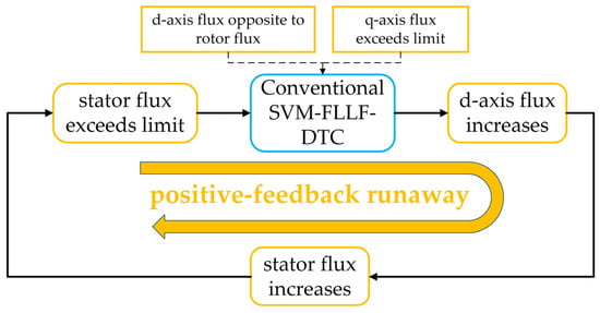
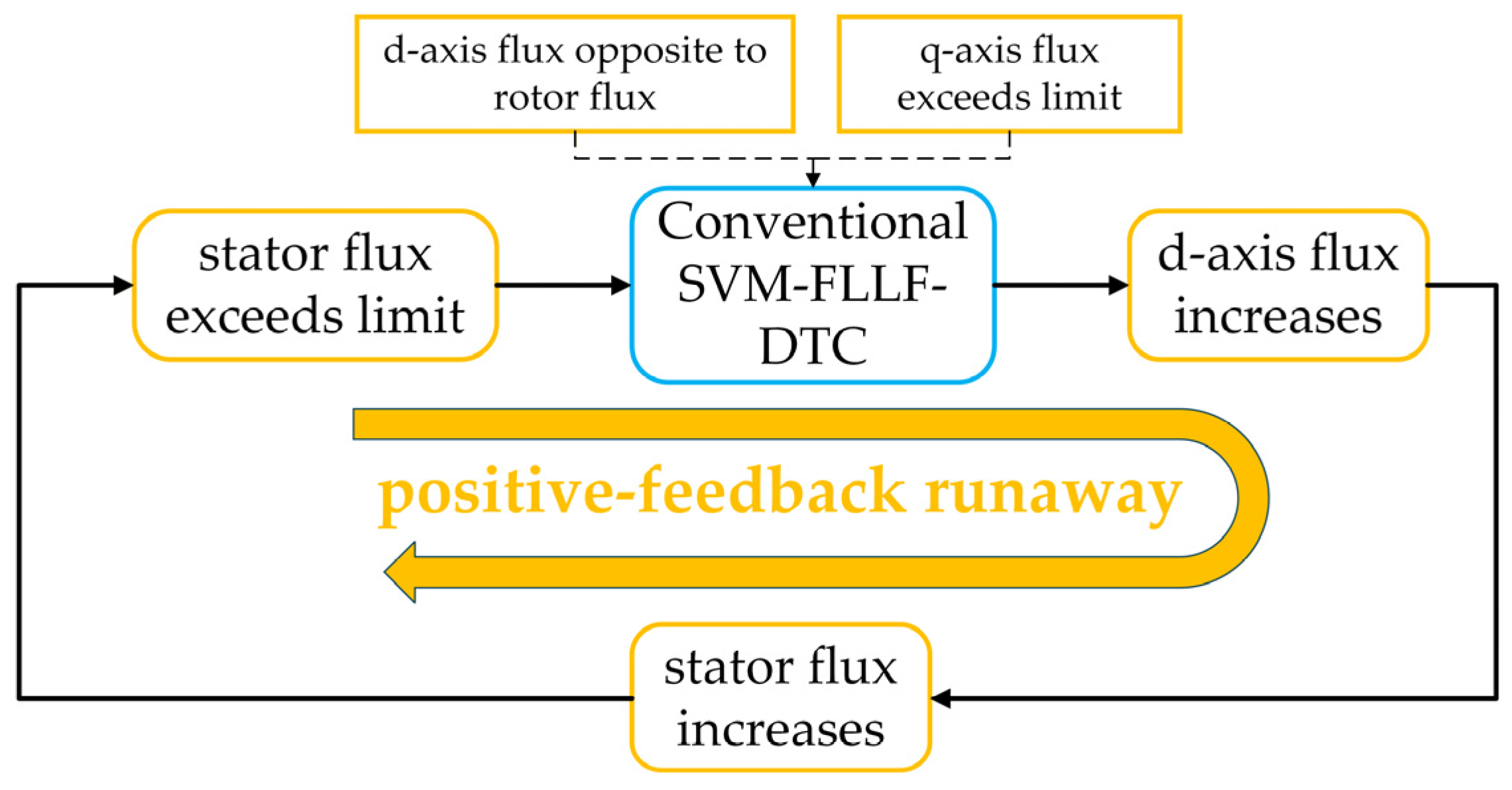
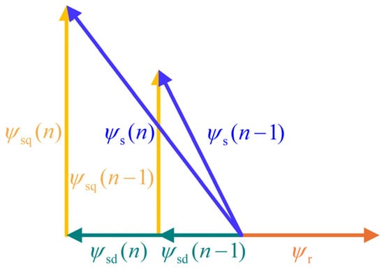
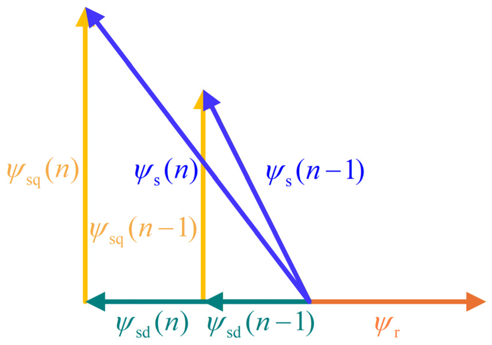
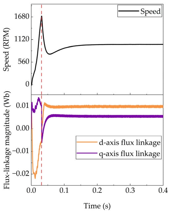
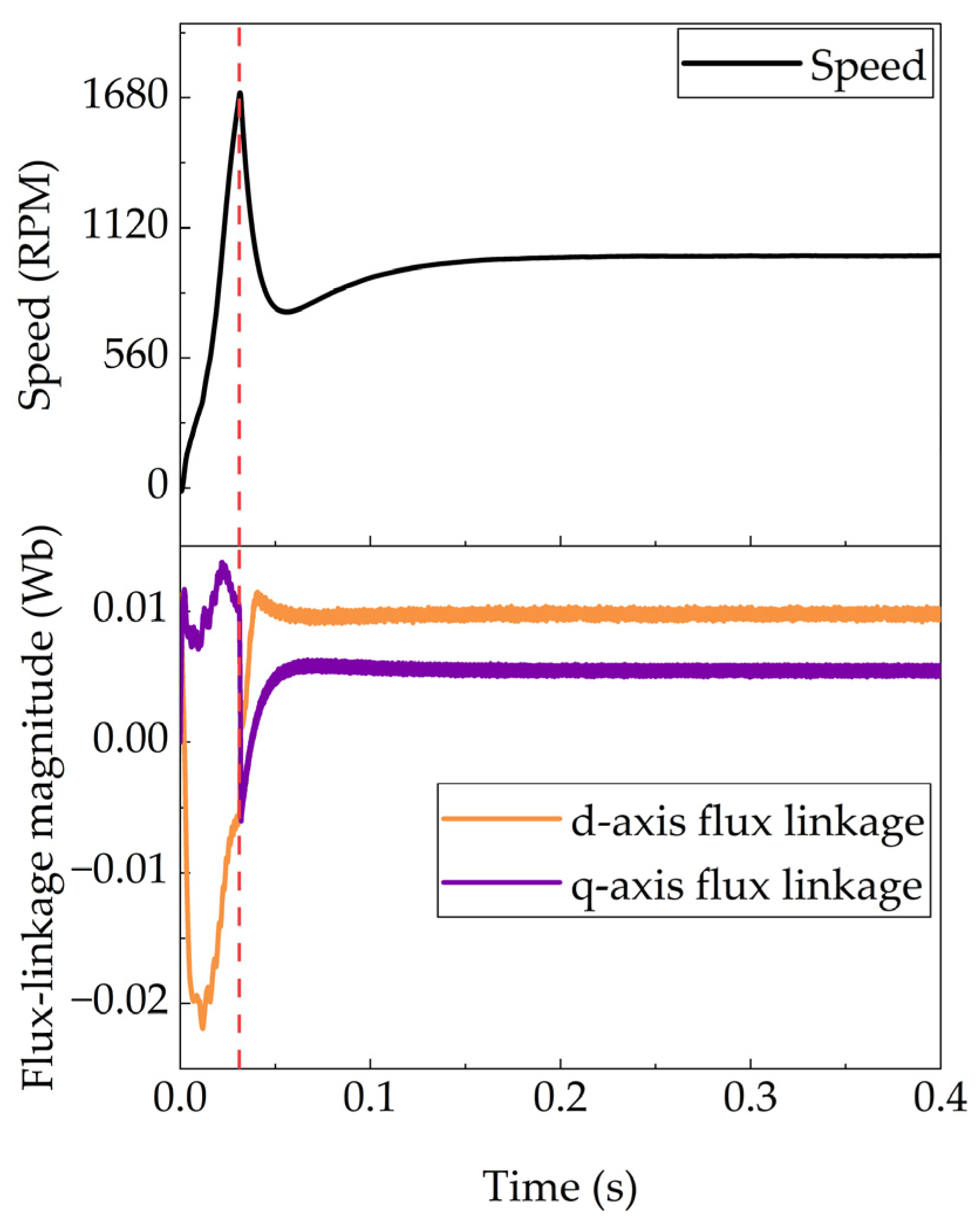
The second problem is the positive-feedback runaway embedded in the conventional flux-linkage limiting strategy. The standard scheme reduces only the d-axis flux linkage to constrain the stator flux magnitude, assuming the q-axis flux linkage remains below the limit [21]. However, when the q-axis flux linkage inadvertently exceeds the limiting value, further reducing the d-axis flux linkage causes it to reverse polarity relative to the rotor flux, which paradoxically increases the total flux magnitude. This forms a destructive positive-feedback loop that can lead to rapid divergence and eventual loss of control, as illustrated in Figure 1 [25,26,27].
Figure 1.
Positive-feedback runaway.
Both problems stem from the same root cause: the absence of a direct closed-loop regulation path for the d-axis flux-linkage component and the lack of a coordinated flux-reference generation mechanism accounting for both d- and q-axis constraints. This insight motivates the present work. A straightforward improvement would be to introduce d-axis current closed-loop regulation with constraints on the d-axis current and torque reference to suppress the runaway. However, this approach retains the torque and current loops, resulting in a less compact structure than direct flux-linkage control. A detailed comparison will be presented in a separate work. This paper pursues a more fundamental resolution: replacing the torque inner loop and the open-loop d-axis voltage control with dual d,q-axis flux-linkage closed loops, thereby eliminating both problems at the structural level.
This paper proposes a flux-vector direct torque control strategy that replaces the torque inner loop and the current regulation loops with two independent proportional controllers directly regulating the d- and q-axis stator flux linkages. A three-scenario flux-reference generation scheme adaptively determines the flux-linkage references, thereby eliminating the magnetization effect and breaking the positive-feedback runaway at the structural level. The sufficiency of proportional control is theoretically justified.
Experimental results obtained from an RCP platform based on a DSP28379D controller validate the feasibility and effectiveness of the proposed FV-DTC strategy. The results demonstrate that the FV-DTC successfully suppresses the magnetization effect, maintains robust dynamic performance under load transients, and significantly improves flux-linkage regulation accuracy.
The remainder of this paper is organized as follows. Section 2 presents the SPMSM mathematical model. Section 3 reviews conventional SVM-FLLF-DTC and analyzes its fundamental limitations. Section 4 proposes the FV-DTC strategy. Section 5 presents simulation and experimental results. Section 6 discusses the findings, and Section 7 concludes the paper.
2. Mathematical Model of the PMSM
All derivations and experiments in this paper are based on the SPMSM, which features a simple magnetic circuit structure and a uniform air gap. Compared with the interior permanent magnet synchronous motor (IPMSM), the SPMSM offers a simpler structure and lower cost, but exhibits relatively weaker field-weakening capability and overload capacity. Its main characteristic is that the d-axis inductance Ld and the q-axis inductance Lq are approximately equal, i.e., Ld = Lq.
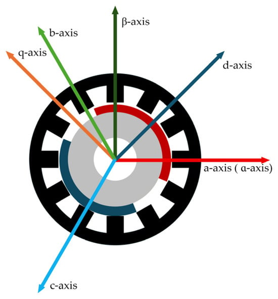
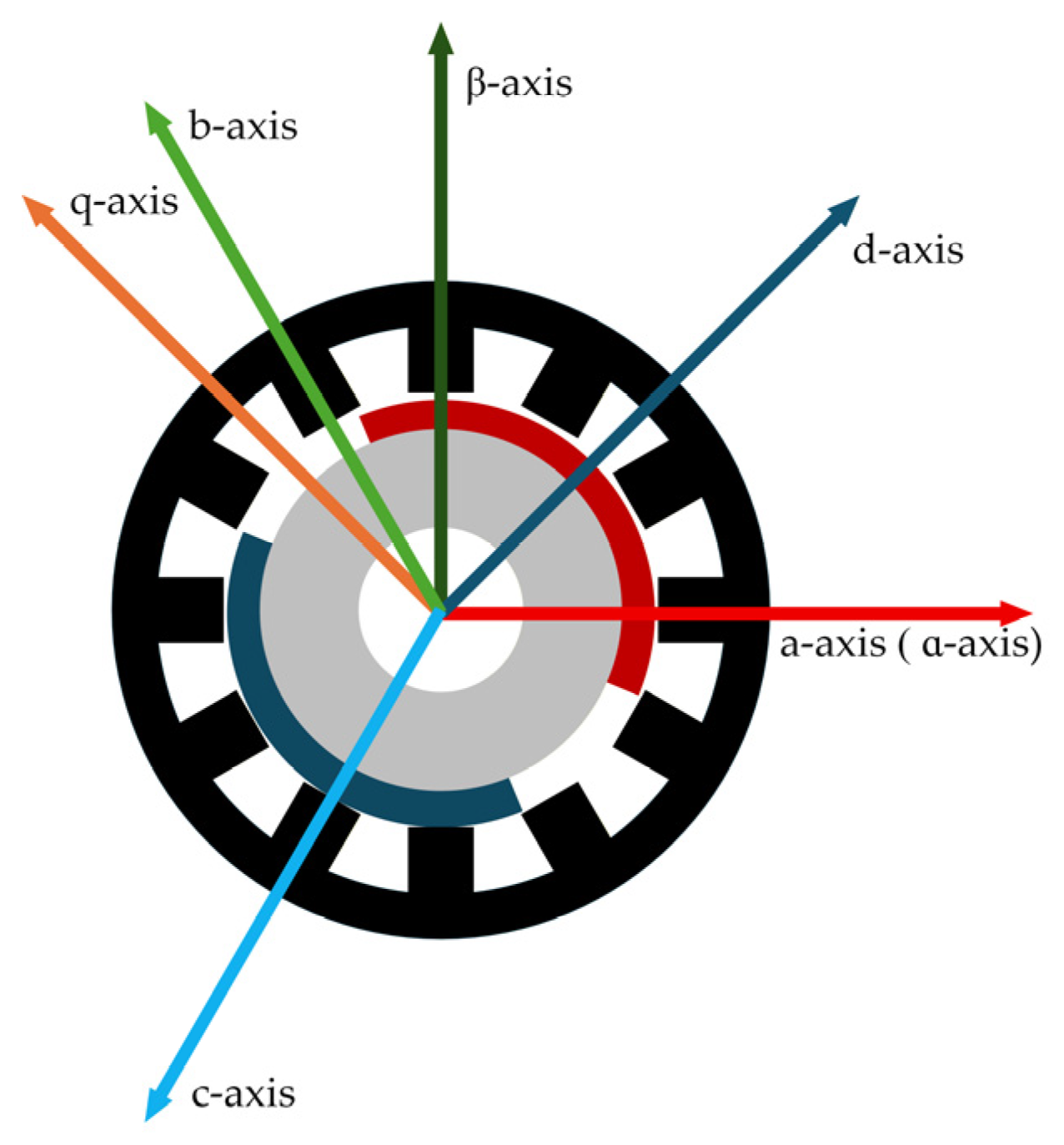
In Figure 2, the three-phase stationary abc reference frame is associated with the stator windings (a, b, and c axes). The two-phase stationary αβ reference frame is derived from the abc frame via the Clarke transformation. The two-phase rotating dq reference frame is associated with the rotor, where the d-axis is aligned with the rotor permanent magnet flux linkage, and the q-axis is orthogonal to the d-axis (leading by 90 degrees). As discussed above, for the SPMSM with uniform air gap, the d- and q-axis inductances are approximately equal.
Figure 2.
Three coordinate frames of the PMSM.
Since the tested motor is star-connected with an isolated neutral and is supplied by a balanced three-leg inverter, the sum of the three phase currents is identically zero, and no zero-sequence current path exists. Under the adopted symmetrical sinusoidal-winding model, the zero-sequence flux-linkage and voltage components are decoupled from torque production and are therefore omitted from the following model. It should be noted that the resulting reduced αβ/dq model would not be sufficient for drives featuring an accessible neutral point, an open-end winding configuration, or zero-sequence-injection-based modulation.
The electrical and mechanical angular quantities are related through the number of pole pairs. Specifically,
where np is the number of pole pairs, ωm is the mechanical angular velocity, θm is the mechanical rotor angle, and θ0 is the electrical alignment offset between the rotor d-axis and the encoder zero reference.
In the αβ reference frame, the relationship among the PMSM flux linkage, voltage, and current is given by the following equation:
where ψsα and ψsβ are the stator α- and β-axis flux linkages, respectively; usα and usβ are the stator α- and β-axis voltages, respectively; iα and iβ are the stator α- and β-axis currents, respectively; and Rs is the stator resistance of the motor.
Transformed into the dq reference frame, the equation becomes:
where ψsd and ψsq are the stator d- and q-axis flux linkages, respectively; usd and usq are the stator d- and q-axis voltages, respectively; and isd and isq are the stator d- and q-axis currents, respectively.
The d,q-axis flux-linkage calculation equations are as follows:
where ψf is the permanent magnet flux linkage.
Substituting Equation (4) into Equation (3) yields the voltage equation of the PMSM:
It should be noted that Equations (4) and (5) are derived under the assumption of constant d- and q-axis inductances. This assumption holds when the magnetic circuit operates in its approximately linear region. In this study, the stator flux-linkage magnitude is explicitly constrained by ψsmax through the proposed three-scenario reference-generation scheme, and the phase currents remain within the rated range in all reported tests. The drive therefore operates within a bounded flux/current envelope in which magnetic saturation effects are minor, and the constant-inductance model is adequate. Operation in the deep-saturation region, where Ld and Lq vary significantly, is outside the scope of this work.
The electromagnetic torque of the PMSM, expressed in terms of the d,q-axis flux linkages, is given by:
Equation (6) consists of two terms: the first term represents the excitation torque of the motor, and the second term represents the reluctance torque characteristic of IPMSMs. For SPMSMs, this term is zero, and the equation can be converted to the following form:
An alternative form of Equation (6) is:
where |ψs| is the stator flux linkage magnitude of the motor, and δ is the torque angle, defined as the angle between the stator flux linkage and the rotor flux linkage.
A more general current-based form of Equation (7) is:
Meanwhile, the mechanical motion of the PMSM satisfies the following equation:
where J is the rotor moment of inertia, TL is the load torque, and B is the damping coefficient.
In real SPMSMs, Ld and Lq may differ by up to approximately 5% owing to manufacturing tolerances; this small mismatch is treated here as a bounded perturbation and was found to have negligible influence within the tested operating envelope. A more general saliency-based model and its extension to IPMSMs are left for future work.
The above equations constitute the mathematical model of the PMSM.
3. Conventional SVM-FLLF-DTC
3.1. Basic Principle of FLLF-DTC
All motor control strategies are, in essence, the control of instantaneous torque. For a PMSM, the electromagnetic torque is generated by the interaction between the stator flux linkage and the permanent magnet flux linkage. The principle of conventional DTC is primarily derived from Equation (8): with the stator flux-linkage magnitude |ψs| held constant, rapidly adjusting the torque angle δ enables fast control of the motor torque. However, varying the stator flux-linkage magnitude |ψs| can also achieve torque control. In conventional DTC, this degree of freedom is deliberately discarded. This choice is motivated not only by structural simplicity but also by physical considerations: raising the flux magnitude above the rated level aggravates magnetic-circuit saturation and iron losses, whereas reducing it below the nominal level weakens the torque capability and increases the current required for a given torque. It is therefore preferable to operate the motor around its nominal magnetization, and the flux-linkage closed loop of conventional DTC provides a simple and reliable means of keeping the stator flux within safe limits. Therefore, an algorithm capable of simultaneously manipulating both the torque angle δ and the stator flux-linkage magnitude |ψs| can achieve more effective torque control of the motor.
In the dq rotating reference frame, the relationship between the electromagnetic torque and the flux linkage of the SPMSM is given by Equation (7). To obtain the relationship between the electromagnetic torque and the voltage, it is first necessary to establish the relationship between the flux linkage and the voltage. The voltage equation of the PMSM incorporating flux-linkage terms in the continuous domain is given by Equation (3).
Observing Equations (3) and (7), differentiating both sides of Equation (7) yields:
Substituting the q-axis flux-linkage derivative from Equation (3) into the differentiated Equation (11) yields:
The stator-resistance term Rs·iq is small in magnitude compared with the other terms and is therefore neglected. It should be emphasized that the term ωeψsd is by no means small. At rated speed, it is comparable in magnitude to uq and cannot be discarded on the basis of magnitude. Nevertheless, within one control period, the rotor speed and the d-axis flux linkage vary only slightly, so ωeψsd behaves as a slowly varying quasi-static bias. Since this bias is identical for all candidate voltage vectors at any given instant, it cancels in the comparison of the candidate vectors. Hence, the vector that maximizes the q-axis voltage component uq still maximizes the instantaneous torque derivative, which yields:
and the resulting voltage-vector selection rule underlying FLLF-DTC remains valid.
The formulation above is also consistent with steady-state operation. In steady state, the flux-linkage derivatives vanish, and Equation (3) gives:
Substituting this relation into Equation (12) yields dTe/dt = 0, which recovers constant-torque operation. Therefore, the torque remains constant in steady state rather than changing continuously, as would be implied if the term ωeψsd were absent from Equation (12).
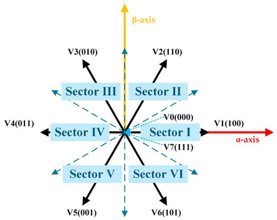
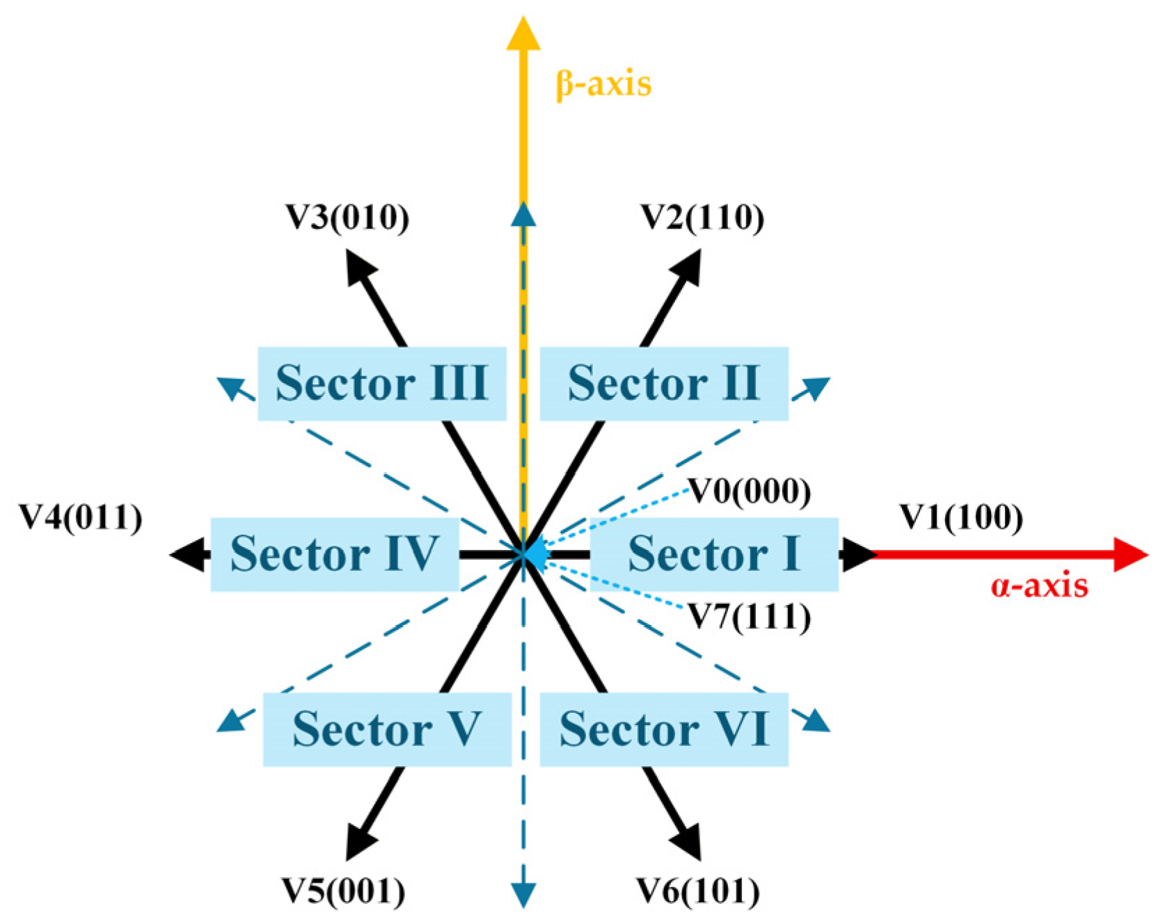
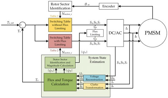
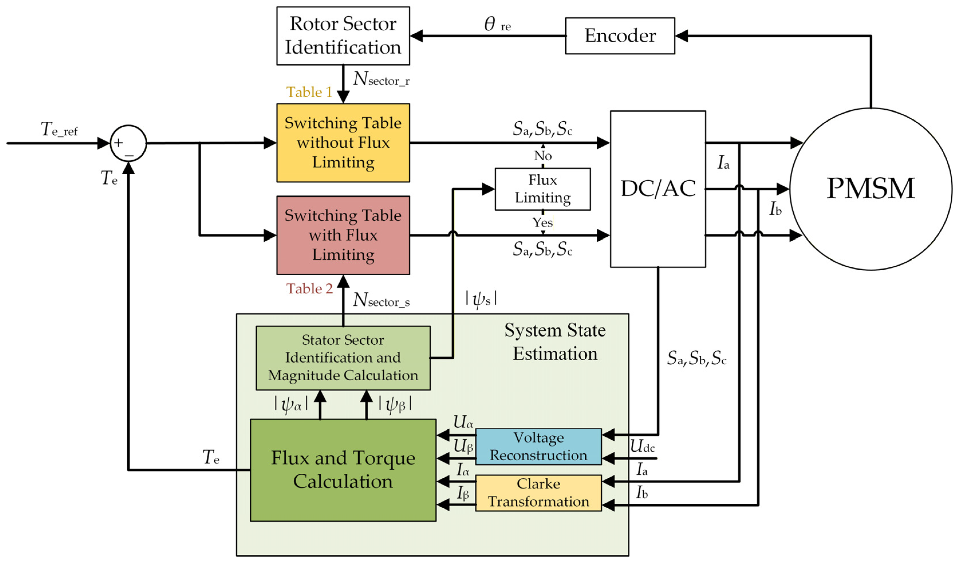
FLLF-DTC eliminates the stator flux-linkage closed loop of conventional DTC and instead operates in a rotating dq reference frame. Within this framework, the voltage vector maximizing the q-axis component is selected to regulate the electromagnetic torque, achieving simultaneous control of the torque angle δ and the stator flux-linkage magnitude |ψs|. The distribution of the voltage vectors is shown in Figure 3. The sector assignment and the corresponding switching table are given in Table 1, and the control block diagram is shown in Figure 4.
Figure 3.
Distribution of voltage vectors.
Table 1.
FLLF-DTC sector assignment and switching table.
Figure 4.
The control block diagram of FLLF-DTC.
However, owing to the lack of direct control over |ψs|, the stator flux-linkage magnitude may exceed the permissible range, leading to iron core saturation, voltage saturation, excessive losses, and potential irreversible demagnetization. Therefore, flux-linkage magnitude limiting is necessary. The conventional limiting principle reconstructs the stator flux linkage in the αβ reference frame, obtains its magnitude and angle, and selects the voltage vector that simultaneously satisfies the torque demand and reduces the flux magnitude. The sector assignment and switching table under the flux-limiting condition are given in Table 2. The basic principle of FLLF-DTC is summarized as follows: the stator flux-linkage magnitude is compared with the limit to choose between Table 1 and Table 2, while the torque error determines whether the torque-increasing or torque-decreasing vector is applied.
Table 2.
FLLF-DTC sector assignment and switching table under flux-limiting condition.
3.2. Basic Principle of SVM-FLLF-DTC
The switching-table-based FLLF-DTC inherits the variable switching frequency and large torque ripple of conventional DTC. To overcome these issues, SVM is introduced into the FLLF-DTC framework, hereinafter referred to as SVM-FLLF-DTC. SVM synthesizes arbitrary reference voltages within each fixed switching period, yielding constant switching frequency, reduced torque ripple, and improved steady-state waveform quality. Introducing SVM into FLLF-DTC is therefore beneficial for improving the output waveform and suppressing torque ripple.
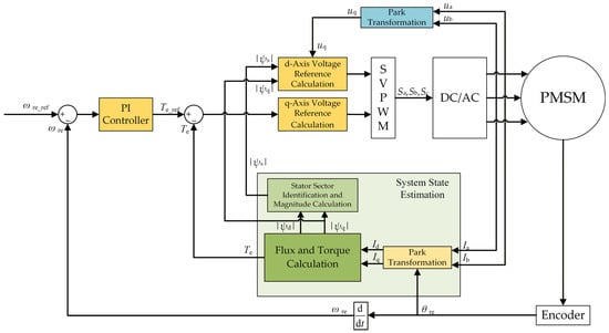
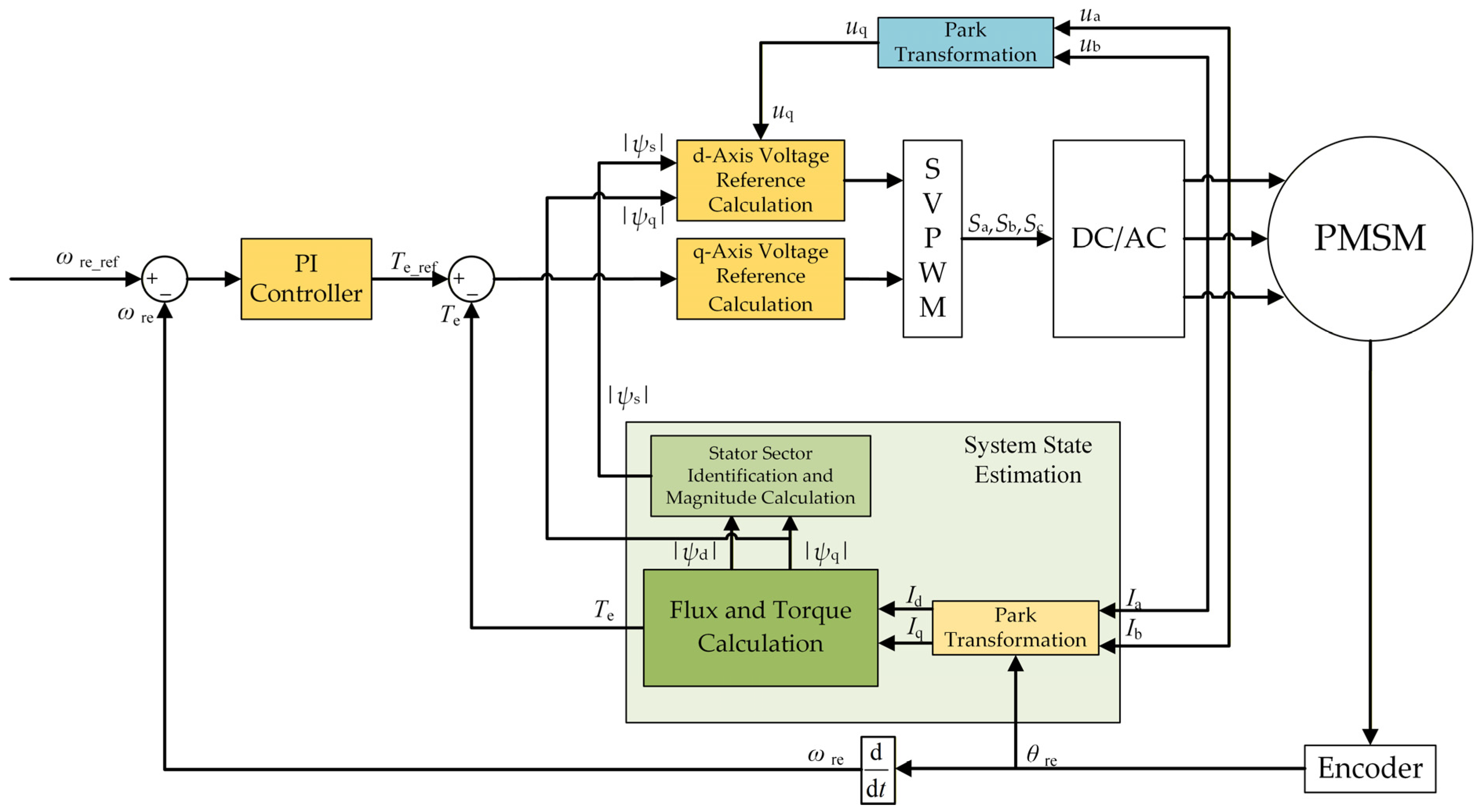
The control block diagram of SVM-FLLF-DTC is illustrated in Figure 5. Unlike the conventional SVM-DTC, in which the flux linkage is maintained constant and the torque angle is controlled, the flux linkage in SVM-FLLF-DTC varies dynamically. Under this condition, the stator d- and q-axis voltages must be regulated according to the control requirements: the q-axis voltage satisfies the torque demand, while the d-axis voltage governs the stator flux-linkage magnitude.
Figure 5.
The control block diagram of SVM-FLLF-DTC.
To satisfy the torque demand, the q-axis voltage reference must first be determined. The relationship between the torque and the q-axis voltage is given by Equation (12). Discretizing this relationship and multiplying both sides of Equation (12) by the control period Ts yields the following equation:
With usq* as the q-axis voltage reference input, Equation (15) can be rewritten as:
Taking speed control as an example, according to Equation (10), the torque reference can be obtained from the speed error via a PI controller.
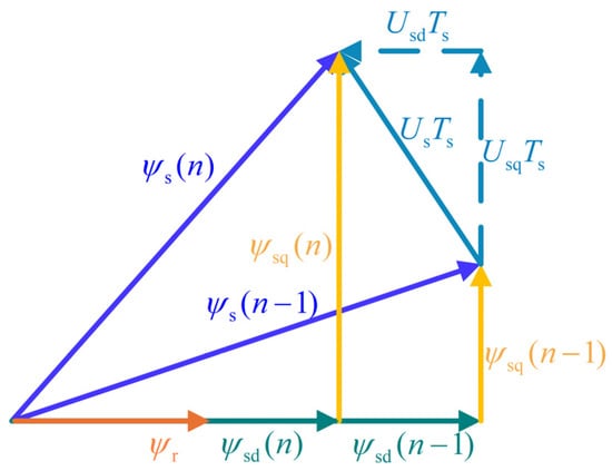
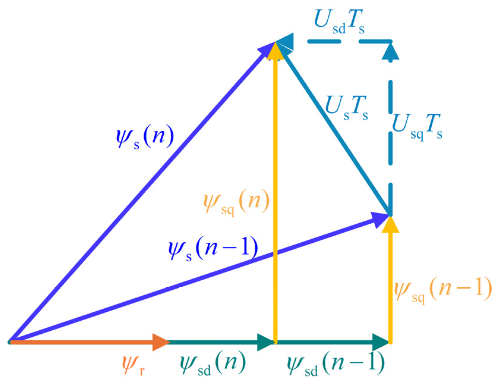
While satisfying the torque demand, the stator flux-linkage limiting must also be addressed. In SVM-FLLF-DTC, the stator flux-linkage magnitude is regulated by controlling the d-axis voltage, which in turn controls the d-axis flux linkage. When the stator flux linkage remains within the limit, no additional control action on the d-axis voltage is required, and the d-axis voltage reference can simply be set to zero. Let ψsmax denote the maximum stator flux-linkage magnitude. The relationship between the voltage and the stator flux linkage under the flux limiting condition is illustrated in Figure 6:
Figure 6.
Stator d,q-axis flux linkages under flux limiting.
When the stator flux linkage operates under saturation, the flux-linkage magnitude must be constrained. Therefore, it can be assumed that ψs(n − 1) = ψs(n) = ψsmax. Based on the geometric relationship, the d,q-axis stator flux linkages then satisfy:
In summary, the stator d-axis voltage usd satisfies:
The stator flux linkage ψsd(n) at time step n in Equation (18) satisfies:
Combining the above equations yields the expression for the stator flux linkage ψsd(n) at time step n as follows:
Substituting Equation (20) into Equation (18) yields the following result. Assuming the current instant is time step n − 1, the d-axis stator voltage reference usd* satisfies usd* = usd. Substituting this condition further yields the expression for the d-axis stator voltage reference usd* as:
Based on the above analysis, under the flux-linkage limiting condition, the voltage references of SVM-FLLF-DTC are given as follows:
The actual electromagnetic torque of the motor and the torque reference in Equation (22) are obtained in the same manner as in FLLF-DTC.
3.3. Limitations of Conventional SVM-FLLF-DTC
Conventional SVM-FLLF-DTC employs only open-loop control of the d-axis voltage, and when addressing the flux-linkage limit, it adjusts only the d-axis flux linkage. This adjustment is typically in the direction opposite to the rotor flux linkage, i.e., the negative direction. When the flux-linkage limit is relatively large, the stator q-axis flux linkage does not exceed the limit, and simply reducing the d-axis flux linkage can effectively constrain the stator flux-linkage magnitude. However, when the flux-linkage limit is relatively small, the q-axis flux linkage may exceed the limit. In this case, continuously reducing the d-axis flux linkage can no longer satisfy the flux-linkage limiting requirement, and the d-axis flux-linkage magnitude reaches a minimum of zero. If the d-axis flux linkage is further reduced according to Equation (22) until its direction becomes opposite to the rotor flux linkage, as illustrated in Figure 7, further reduction in the d-axis flux linkage without decreasing the q-axis flux linkage will only cause the stator flux-linkage magnitude to increase further.
Figure 7.
Stator d,q-axis flux linkages with the d-axis flux opposite to the rotor flux.
A necessary condition for Equation (22) to effectively constrain the stator flux-linkage magnitude is that ψsd > 0 and ψsq < ψsmax. If the d-axis flux linkage falls below zero, the d-axis voltage selected by the flux-limiting scheme will only further increase the flux-linkage magnitude. If the q-axis flux linkage exceeds the limiting value, the overall stator flux-linkage magnitude will inevitably exceed the limiting value.
In summary, conventional SVM-FLLF-DTC cannot effectively regulate the d-axis flux linkage. This may cause the d-axis flux linkage to reverse its direction relative to the rotor flux linkage, driving the overall system into a positive-feedback loop, as illustrated in Figure 1, which ultimately leads to loss of control. Moreover, it is difficult to balance the relationship between the d- and q-axis flux linkages: the q-axis flux-linkage magnitude may exceed the flux-linkage limit and continue to increase while the d-axis flux linkage is already opposite to the rotor flux linkage, further intensifying the positive feedback and causing the flux-linkage magnitude to increase rather than decrease. These inherent limitations of conventional SVM-FLLF-DTC necessitate an improved flux-linkage regulation strategy to achieve effective control of the flux-linkage magnitude.
4. Proposed FV-DTC
4.1. Design Rationale and Overall Architecture
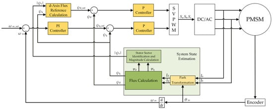
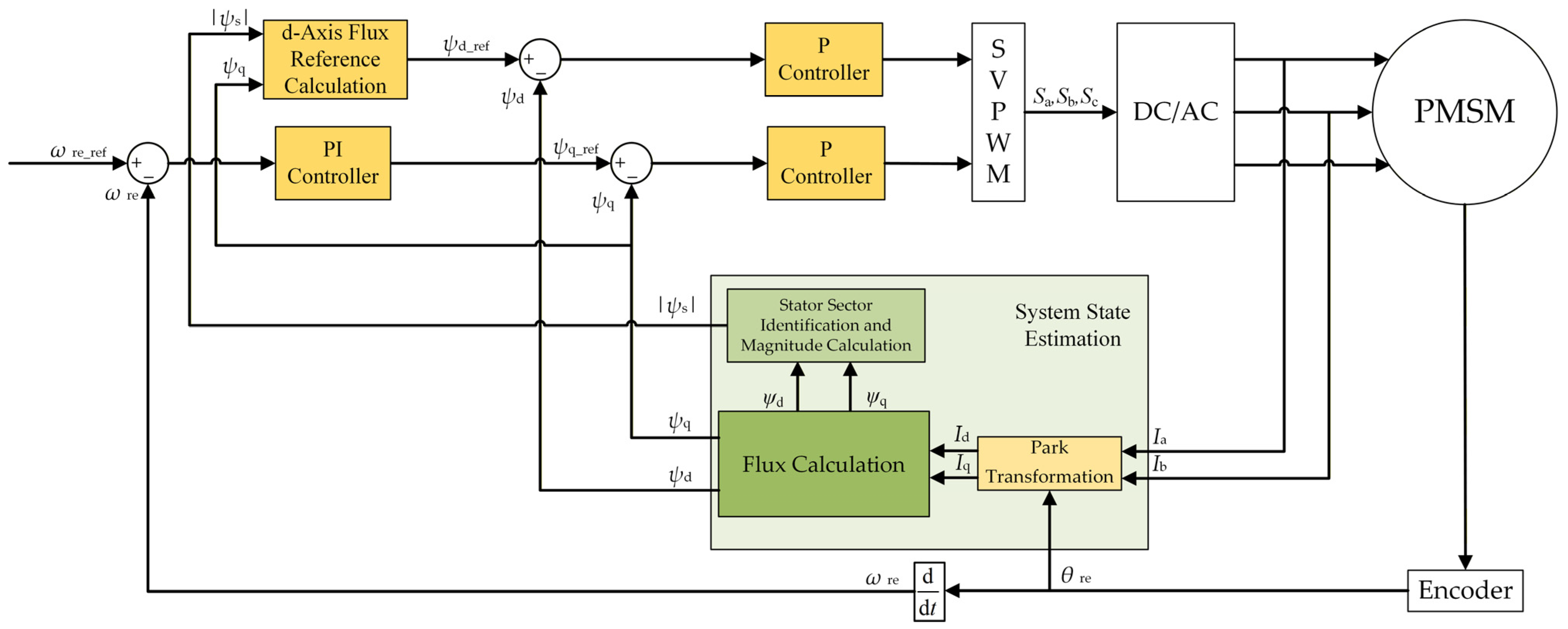
From the above derivation, it can be observed that conventional SVM-FLLF-DTC suppresses the stator flux-linkage magnitude solely by applying a specific negative d-axis voltage, which equivalently reduces the d-axis flux linkage. However, this approach not only triggers positive-feedback runaway and leads to the failure of flux-linkage limiting, but also, owing to the lack of a direct control mechanism for the d-axis flux linkage, leaves the d-axis voltage in an open-loop state under non-limiting operating conditions. This inherently gives rise to a magnetization tendency, which further degrades the operating efficiency. Therefore, an effective flux-linkage limiting method is urgently required. Directly regulating the flux-linkage magnitude can substantially simplify the system structure and reduce the computational burden. Motivated by this idea, this section proposes a flux-vector direct torque control (FV-DTC) strategy, whose overall control block diagram is illustrated in Figure 8. The proposed algorithm replaces both the original torque closed loop and the voltage open-loop control with flux-linkage closed loops. Although FV-DTC introduces d,q-axis flux-linkage loops and therefore is no longer ‘flux-linkage-loop-free’ in the strict sense, it inherits the rotating-frame, single-inner-loop architecture of SVM-FLLF-DTC and requires neither a stator-flux-magnitude/angle observer nor cascaded current loops.
Figure 8.
The control block diagram of FV-DTC.
The control structure of FV-DTC comprises the following core modules: a speed outer-loop PI controller, whose output is the q-axis flux-linkage reference ψsq*; a d,q-axis flux-linkage calculation module, which estimates the instantaneous stator d,q-axis flux-linkage components ψsd and ψsq from the sampled currents; two independent proportional (P) flux controllers for the d- and q-axes, each receiving the deviation between the corresponding flux-linkage reference and its actual value, and outputting the d,q-axis voltage references usd* and usq*, which are then fed to a space vector modulation (SVM) unit to generate the inverter drive signals; and a three-scenario flux-reference generation module, which adaptively determines ψsd* and ψsq* according to the constraint status of the stator flux-linkage magnitude |ψs| and the q-axis flux-linkage magnitude ψsq.
Compared with the conventional SVM-FLLF-DTC shown in Figure 5, FV-DTC differs in three fundamental structural aspects:
- The d-axis voltage control is upgraded from open-loop to closed-loop. In the conventional scheme, the d-axis voltage is fixed at zero under non-limiting conditions and is assigned a calculated value only when the flux-linkage limit is exceeded, which essentially constitutes open-loop control and cannot suppress the drift in the d-axis flux linkage. FV-DTC introduces a d-axis flux P controller, ensuring that the d-axis flux linkage remains under closed-loop regulation at all times.
- The torque inner loop is replaced by a q-axis flux-linkage closed loop. The conventional scheme takes the electromagnetic torque as the inner-loop control variable and must compute the q-axis voltage reference from the torque error. FV-DTC directly regulates the q-axis flux linkage. According to Equation (7), the electromagnetic torque of an SPMSM is proportional to ψsq. Controlling ψsq is therefore equivalent to controlling the torque, while eliminating the torque-to-voltage conversion step.
- The flux-linkage limiting logic is upgraded from single-axis constraint to three-scenario coordination. The conventional scheme only reduces the d-axis flux linkage when the stator flux-linkage magnitude exceeds the limit, without accounting for the influence of the q-axis flux linkage. FV-DTC simultaneously monitors both |ψs| and ψsq, and adaptively switches ψsd* and ψsq* according to the three-scenario logic, thereby fundamentally eliminating the condition that triggers the positive-feedback runaway.
In terms of hardware implementation, the d,q-axis flux linkages in FV-DTC can be directly calculated by applying the Park transformation to the sampled three-phase currents and then computing the flux linkages using the motor inductance parameters. No additional flux-linkage observer is required. Both flux regulators are purely proportional controllers, requiring neither integral nor derivative action, and their mathematical justification is rigorously established in Section 4.2. The three-scenario flux-reference generation scheme is fully developed in Section 4.3.
4.2. Analysis and Design of Proportional Flux Control
This section first derives the input–output relationship of the flux-linkage closed-loop control loop, theoretically demonstrates the sufficiency of a proportional (P) controller, provides the engineering tuning method for the proportional gain, and finally discusses the interface between the speed outer loop and the flux-linkage inner loop.
4.2.1. Proportional Controller Design Under Ideal Conditions
Neglecting the stator resistance voltage drop and the back-electromotive force terms, the relationship between the d,q-axis voltage and the flux linkage is:
The above equation can be written in a unified form as:
where ψ is the stator d,q-axis flux linkage, and u is the stator d,q-axis voltage.
Applying the Laplace transform to Equation (24) yields:
where s is the Laplace variable.
If a proportional controller is adopted and the flux-linkage reference is denoted as ψ*, the relationship between the controller input and output is:
Combining Equations (25) and (26) yields:
This is a typical first-order lag system. From the structure of its transfer function, the following three key properties can be directly obtained:
- Nominal asymptotic stability. Under the ideal continuous-time model of Equation (21), the closed-loop pole is s = −Kp. Therefore, the nominal flux-linkage closed loop is asymptotically stable for Kp > 0. It should be emphasized that this conclusion applies to the idealized unsaturated continuous-time model. The effects of the motor-model disturbances, digital implementation delay, and inverter voltage limitation are considered separately in the following subsection.
- Zero steady-state error. Under a step reference, the final value theorem gives ψ(∞) = ψ*. The plant itself contains an integral element (1/s), which eliminates the steady-state error without requiring an integral term in the controller.
- Overshoot-free response. The system is a first-order lag element with time constant τ = 1/Kp, whose step response rises monotonically without overshoot.
In summary, under ideal conditions, the flux-linkage closed-loop controller requires only a proportional element with Kp > 0 to simultaneously guarantee global asymptotic stability, zero steady-state error, and an overshoot-free response. This conclusion is mathematically identical in structure to the proportional control derivation for the position loop in a position servo system.
4.2.2. Robustness Analysis and Engineering Implementation
The analysis in the preceding subsection is based on an ideal continuous-time model in which the stator-resistance voltage drop, rotational back-EMF, d,q-axis cross-coupling, digital implementation delay, and inverter voltage saturation are neglected. Therefore, the asymptotic-stability conclusion obtained from Equation (24) applies to the nominal flux-linkage closed loop, rather than to the complete practical drive system. This subsection further analyzes the influence of the main nonideal factors encountered in practical implementation.
- Robustness against stator resistance, back-EMF, and d,q-axis cross-coupling
The complete d,q-axis stator-flux dynamics can be written as:
where
and
collects the stator-resistance voltage drop, rotational back-EMF, and d,q-axis cross-coupling terms.
Define the flux-linkage tracking error as:
The proportional flux controller is expressed as:
Substituting the controller expression into the flux dynamics gives:
For the inner-loop stability analysis, the flux-linkage reference can be regarded as constant or slowly varying over one inner-loop transient. The reference-rate term may therefore be included together with the motor-model nonidealities by defining the equivalent disturbance:
Accordingly,
Within the admissible operating range of the drive, the motor currents, rotor speed, and stator flux linkages are bounded. Hence, the equivalent disturbance is also bounded, i.e.,
Consider the Lyapunov candidate:
Its time derivative along the trajectories of the error dynamics is:
Using the Cauchy–Schwarz inequality gives:
or equivalently:
Therefore,
This result shows that the neglected stator-resistance, back-EMF, and cross-coupling terms do not generally preserve exact zero-error asymptotic convergence. Instead, they act as bounded disturbances to the nominal flux-linkage loop. The resulting tracking error remains bounded and decreases as Kp increases. Hence, the practical closed loop exhibits input-to-state-stable behavior with respect to these bounded disturbances.
This result also explains why explicit d- and q-axis decoupling terms are not strictly required in the proposed controller. Although the cross-coupling terms are omitted from the nominal controller model, their influence appears as a deviation of the actual flux linkage from its reference. Through the closed-loop proportional feedback, this deviation automatically generates a compensating voltage. Consequently, the coupling effect is suppressed implicitly by the flux-linkage feedback loop rather than explicitly cancelled by feedforward decoupling.
For example, under steady-state q-axis operation:
which gives approximately
Thus, a finite flux-linkage error is required for a purely proportional controller to generate the voltage necessary to compensate the resistance drop and rotational electromotive force. This explains the small steady-state flux-linkage error observed experimentally, particularly at elevated speeds.
- 2.
- Effect of digital implementation delay
The preceding analysis assumes continuous-time implementation. In the digital controller, however, current sampling, coordinate transformation, control computation, and PWM update introduce a finite delay. To investigate its influence, the nominal flux-linkage dynamics are discretized with the sampling period Ts:
Without computational delay, substituting:
gives:
Therefore, the nominal discrete-time system is stable if:
which yields:
The error dynamics then become:
The corresponding characteristic equation for each flux axis is:
Applying the Jury stability criterion gives the discrete-time stability condition:
In the implemented controller:
In addition, since:
the selected proportional gain satisfies the discrete-time stability requirement even under the conservative assumption of a full one-sample computational delay. This also provides an additional theoretical justification for selecting Kp = 0.8/Ts rather than the nominal deadbeat value Kp = 1/Ts.
- 3.
- Effect of inverter voltage saturation
The previous derivations also assume that the voltage commanded by the flux controller can be fully synthesized by the inverter. In practice, the available stator voltage is limited by the DC-link voltage and the SVM modulation range. The applied voltage can therefore be represented as:
where Umax denotes the maximum available stator-voltage magnitude.
Consequently, the linear first-order dynamics derived in Section 4.2.1 are valid only when:
When the voltage command exceeds the available inverter voltage, the actuator enters saturation and the closed-loop response is no longer described exactly by the nominal linear model.
Nevertheless, stable flux regulation remains feasible provided that the inverter retains sufficient voltage authority to overcome the equivalent motor disturbance. A necessary practical condition is:
Under this condition, even if the controller temporarily enters voltage saturation during a large transient, the available voltage remains sufficient to oppose the disturbance and drive the flux-linkage error back toward the unsaturated region. Once:
the controller returns to the linear operating region and the ultimate-bound result derived above again applies.
The proposed three-scenario flux-reference generation scheme further reduces the likelihood of persistent voltage saturation. In this scheme, the maximum admissible stator flux linkage ψsmax is selected according to the voltage and current constraints of the motor drive. By adjusting the d- and q-axis flux-linkage references when the stator flux approaches this limit, the demanded flux vector is maintained within the feasible operating envelope of the drive.
It should nevertheless be emphasized that the above voltage-margin condition is a practical feasibility condition rather than a proof of global asymptotic stability for the complete saturated nonlinear drive system.
- 4.
- Summary of the practical stability interpretation
The stability conclusions of the proposed flux-linkage controller can be summarized at three levels.
First, for the ideal continuous-time plant:
the proportional flux controller yields an asymptotically stable nominal first-order closed loop for Kp > 0.
Second, when stator resistance, rotational back-EMF, d,q-axis cross-coupling, and bounded reference variations are included, these terms can be regarded as bounded disturbances. The practical flux-linkage tracking error is then ultimately bounded according to:
Third, with a conservative one-sample digital delay, the discrete-time nominal system remains stable provided that:
The implemented value Kp = 0.8/Ts satisfies this condition. Voltage saturation further restricts the region in which the nominal linear dynamics apply, and reliable flux regulation requires sufficient inverter voltage margin relative to the back-EMF, resistive voltage drop, and cross-coupling terms.
Accordingly, the proposed controller should not be interpreted as establishing global asymptotic stability of the complete practical PMSM drive including all nonlinearities and implementation constraints. Rather, the analysis establishes nominal asymptotic stability, bounded-disturbance robustness, and a discrete-time stability condition under the considered implementation delay, while the simulation and experimental results verify the effectiveness of the controller within the tested operating envelope.
4.3. Three-Scenario Flux-Reference Generation Scheme
As analyzed in Section 3.3, the positive-feedback runaway in conventional SVM-FLLF-DTC originates from the fact that the flux-linkage limiting strategy constrains the stator flux linkage solely from the d-axis, without incorporating the q-axis flux linkage into coordinated control. When the q-axis flux linkage has already exceeded the limit, further reducing the d-axis flux linkage in the negative direction paradoxically increases the resultant flux-linkage magnitude, forming a vicious cycle. FV-DTC simultaneously monitors both |ψs| and ψsq as state variables, classifies the operating condition into three scenarios according to their constraint statuses, and adaptively switches the d,q-axis flux-linkage references.
Let ψsmax denote the upper limit of the stator flux-linkage magnitude, which is jointly determined by the voltage limit and the current limit of the motor. Let ψsdmin denote the admissible lower bound of the d-axis flux linkage. To prevent irreversible demagnetization of the permanent magnets caused by excessive negative d-axis current during deep field weakening, ψsdmin must be appropriately selected according to the demagnetization curve of the permanent magnet material. In this paper, ψsdmin = 0.2 ψf is adopted. From the flux-linkage vector composition relationship |ψs|2 = ψsd2 + ψsq2 ≤ ψsmax2, when the d-axis flux linkage reaches its minimum value ψsdmin, the maximum admissible q-axis flux linkage is:
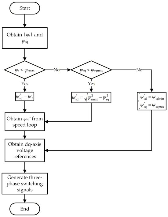
In each control period, |ψs| is first calculated and compared with ψsmax to obtain the first-level judgment. If |ψs| > ψsmax, ψsq is further compared with ψsqmax to obtain the second-level judgment. The two-level judgment yields three scenarios.
The switching logic of the three scenarios is illustrated in Figure 9. The determination of the d,q-axis flux-linkage references under each scenario is presented below.
Figure 9.
Flowchart of FV-DTC.
4.3.1. Scenario I: Normal Operation
Condition: |ψs| < ψsmax
References: ψsd* = ψf, and ψsq* is provided by the speed outer-loop PI controller.
Rationale: Under non-limiting conditions, the d-axis voltage in conventional SVM-FLLF-DTC is fixed at zero, leaving the d-axis flux linkage in an open-loop state. Owing to the d,q-axis cross-coupling, the d-axis flux linkage inherently exhibits a magnetization tendency, resulting in increased iron losses and reduced efficiency. FV-DTC actively clamps ψsd* at ψf, driving the d-axis current to zero. The motor thus operates persistently at the MTPA optimal operating point (isd = 0 for an SPMSM), eliminating the magnetization effect at its root. According to Equation (7), Te is proportional to ψsq, and therefore ψsq* is completely equivalent in control effect to Te* output by the speed loop.
4.3.2. Scenario II: d-Axis-Limited Operation
Condition: |ψs| ≥ ψsmax and ψsq ≤ ψsqmax
References: ψsd* = √(ψsmax2 − ψsq2), and ψsq* is provided by the speed outer-loop PI controller.
Rationale: From |ψs|2 = ψsd2 + ψsq2 ≤ ψsmax2, the admissible upper bound of the d-axis flux linkage is ψsd ≤ √(ψsmax2 − ψsq2). Taking the equality yields ψsd* = √(ψsmax2 − ψsq2), which brings the flux linkage exactly back to the limit. This expression is determined analytically from the geometric relationship and requires no iterative computation. As ψsq increases, ψsd* decreases automatically, releasing flux-linkage margin for the q-axis. When ψsd* falls below ψsdmin, the system transitions to Scenario III. In this scenario, the torque remains freely regulated by the speed loop through ψsq*, unaffected by the limiting action. Only the d-axis flux linkage is passively weakened to satisfy the flux-linkage constraint, maximally preserving the torque dynamic response.
4.3.3. Scenario III: q-Axis-Limited Operation
Condition: |ψs| > ψsmax and ψsq > ψsqmax
References: ψsd* = ψsdmin, ψsq* = ψsqmax.
Rationale: This scenario is the triggering condition for positive-feedback runaway in conventional SVM-FLLF-DTC. At this stage, the d-axis flux linkage has already reached its lower bound, leaving no further flux-weakening margin. If the conventional scheme is followed by continuing to reduce the d-axis flux linkage in the negative direction, ψsd will cross zero and reverse its polarity, paradoxically increasing the resultant flux-linkage magnitude and forming positive feedback that ultimately leads to loss of control. FV-DTC adopts a fundamentally different strategy: ψsd* is fixed at ψsdmin to prevent zero-crossing, while a hard constraint ψsq* = ψsqmax is imposed on the q-axis flux linkage. In this case, the stator flux-linkage magnitude is |ψs| = √(ψsdmin2 + ψsqmax2) = ψsmax, exactly satisfying the limiting requirement. By recognizing the critical condition ψsq > ψsqmax, this strategy cuts off the positive-feedback path that would otherwise continue to reduce the d-axis flux linkage, thereby eliminating the positive-feedback runaway at the mechanism level.
4.3.4. Summary
The triggering conditions and reference values for the three scenarios are summarized in Table 3.
Table 3.
Triggering conditions and reference values.
The three-scenario scheme resolves the two fundamental deficiencies of conventional SVM-FLLF-DTC at the mechanism level through coordinated allocation of the d,q-axis flux-linkage references. Scenario I eliminates the magnetization effect by actively clamping the d-axis flux linkage at ψf. Scenario III cuts off the positive-feedback path by recognizing the q-axis over-limit condition and imposing a constraint on ψsq*. Scenario II maximally preserves the torque dynamic response while guaranteeing flux-linkage safety.
5. Simulation and Experimental Verification
5.1. Simulation and Experimental Setup
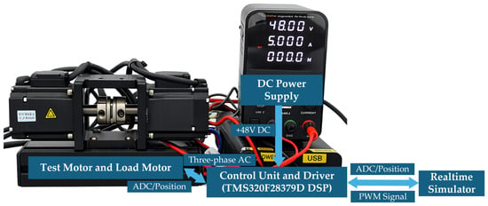
The validation was performed on a real-time test platform based on a TMS320F28379D DSP. The experimental setup is shown in Figure 10. The PWM and control frequencies were both set to 10 kHz, corresponding to a control period of Ts = 100 μs. The DC-link voltage was 48 V. In the simulation mode, both the control algorithms and the plant models were executed on the simulator, enabling the reproduction of unsafe conditions, such as the positive-feedback runaway, without hardware damage.
Figure 10.
The real-time experimental platform based on a TMS320F28379D DSP controller and a real-time simulator.
The validation was performed on a platform combining a TMS320F28379D DSP evaluation board and a real-time simulation environment. The PWM and control frequencies were both set to 10 kHz, corresponding to a control period of Ts = 100 μs. The DC-link voltage was 48 V. In the simulation mode, the control algorithms and the SPMSM/inverter plant models were co-executed entirely within the real-time simulation environment, enabling the safe reproduction of hazardous operating conditions such as the positive-feedback runaway. In the experimental mode, the control algorithms ran in the real-time simulation environment, which directly generated the ePWM signals. These ePWM signals were transmitted to the TMS320F28379D DSP evaluation board, which produced the PWM gate signals to drive a real three-phase inverter. The inverter supplied three-phase AC voltage to the real SPMSM. The phase currents and rotor position were acquired by the DSP evaluation board and fed back to the control algorithms in the simulation environment, forming a rapid control prototyping (RCP) configuration. Three strategies were compared: the conventional SVM-FLLF-DTC, the improved SVM-FLLF-DTC with d-axis current closed-loop regulation, and the proposed FV-DTC.
For a more comprehensive evaluation of the proposed FV-DTC, the improved SVM-FLLF-DTC with d-axis current closed-loop regulation is also evaluated, both in simulation and in an experiment. In addition to replacing the open-loop d-axis voltage command with a d-axis current PI regulator, this approach suppresses the positive-feedback runaway by imposing constraints on both the d-axis current and the torque reference, following a rationale similar to that described in Section 4.3. The detailed implementation and independent analysis will be reported in a separate work; only the results are cited herein as a performance reference.
5.2. Simulation Results
The performance of the conventional SVM-FLLF-DTC, the SVM-FLLF-DTC with d-axis current closed-loop regulation, and the proposed FV-DTC was verified on a simulation platform. The motor parameters used in both the simulation and the experiment are listed in Table 4.
Table 4.
Motor parameters.
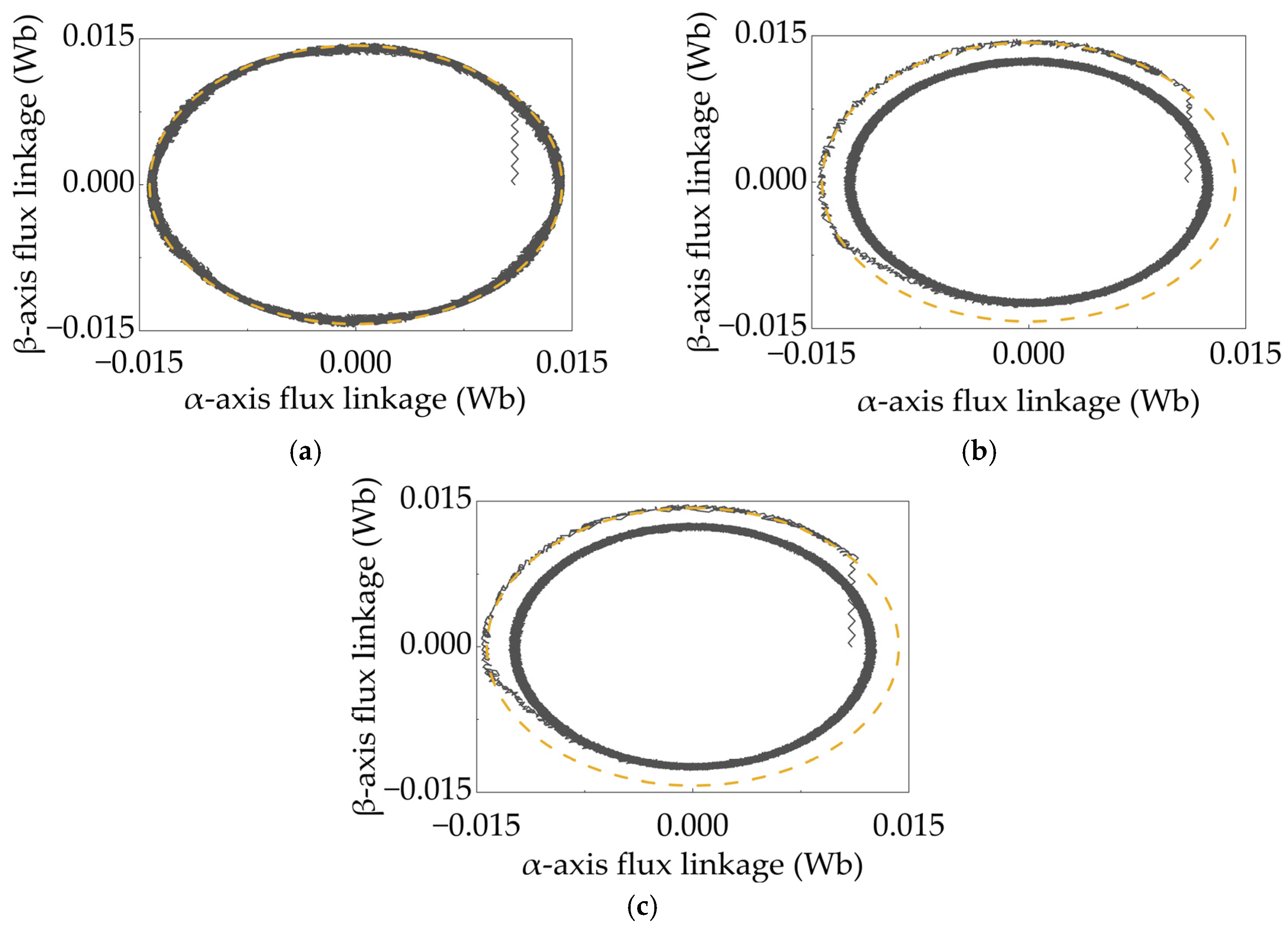
The flux-linkage limit was set to 0.01 Wb, the speed reference to 1000 rpm, and the load torque to 0.4 N·m. The comparison of the flux-linkage trajectories in the αβ plane is shown in Figure 11.
Figure 11.
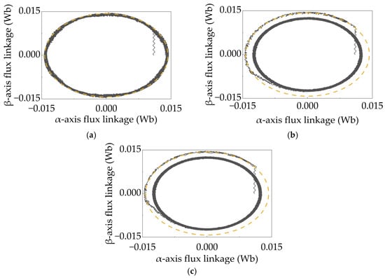
Flux-linkage trajectories of different algorithms in the αβ reference frame under high flux-linkage limit (0.0143 Wb). (a) Conventional SVM-FLLF-DTC; (b) d-axis-current-loop SVM-FLLF-DTC; (c) FV-DTC. The dashed line indicates the stator flux linkage limit of 0.0143 Wb.
Figure 11 presents the flux-linkage trajectories of the three algorithms under a relatively high flux-linkage limit (0.0143 Wb). It can be observed from the figure that, although the conventional algorithm maintains the stator flux-linkage magnitude within the limiting range, it exhibits considerable oscillation, and its steady-state magnitude is notably larger than those of the two improved algorithms.
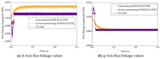
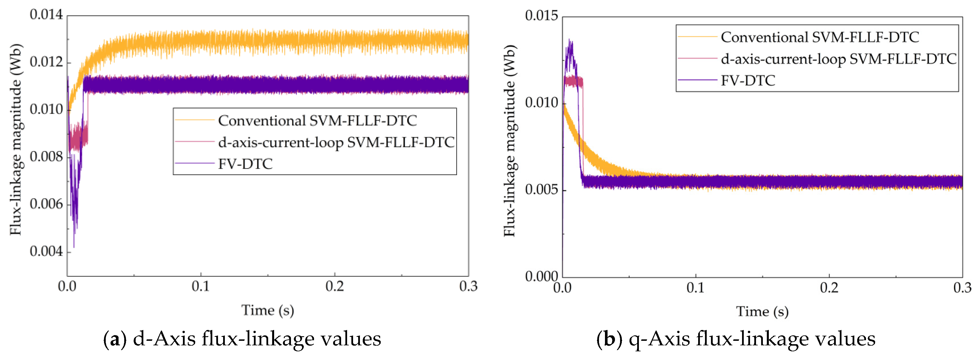
As shown in Figure 12, the steady-state d-axis flux-linkage magnitude of the conventional algorithm is significantly larger than those of the two improved algorithms, whereas both improved algorithms maintain their d-axis flux-linkage magnitudes near the permanent magnet flux-linkage value. The conventional algorithm exhibits a pronounced magnetization effect, which is determined by its open-loop d-axis voltage control characteristic. This leads to significant losses and may even affect the permanent magnets.
Figure 12.
d,q-Axis flux-linkage values of different algorithms. (a) d-Axis flux-linkage values; (b) q-axis flux-linkage values.
It can also be observed that the d,q-axis flux-linkage distributions of the two improved algorithms are significantly better than that of the conventional algorithm. During the acceleration phase, the flux-linkage-loop-based improved algorithm exhibits the lowest d-axis flux linkage, followed by the current-loop-based improved algorithm, whereas the conventional algorithm yields the highest. Correspondingly, the flux-linkage-loop-based improved algorithm achieves the highest q-axis flux linkage during acceleration, followed by the current-loop-based improved algorithm, with the conventional algorithm producing the lowest. A higher q-axis flux linkage corresponds to a greater electromagnetic torque output, and thus a higher acceleration of the motor.
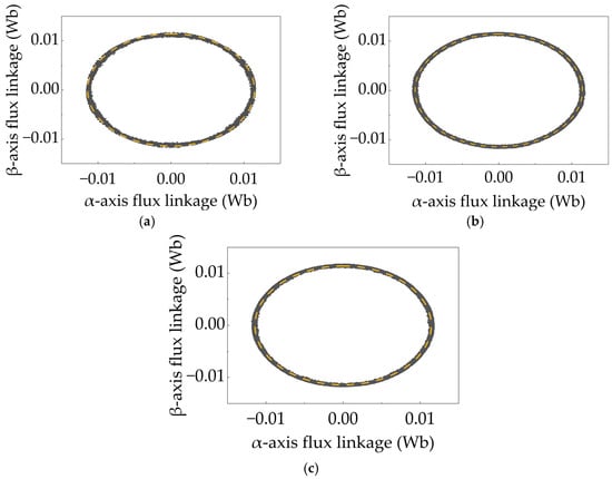
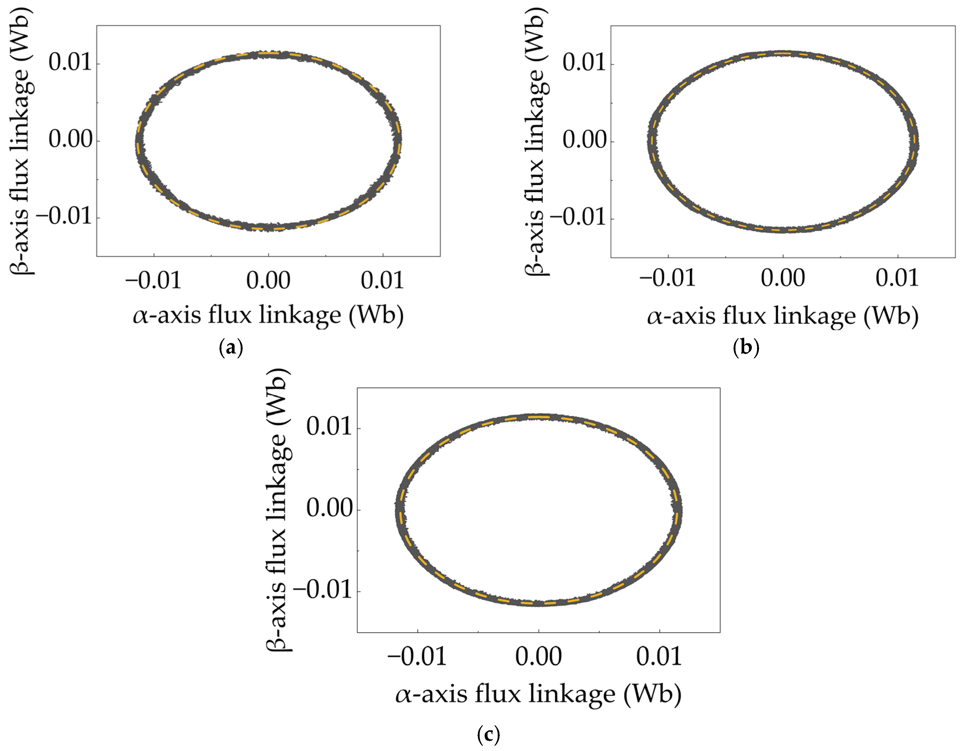
The flux-linkage limit was set to 0.001144 Wb, the speed reference to 1000 rpm, and the load torque to 0.4 N·m. The comparison of the flux-linkage trajectories in the αβ reference frame is shown in Figure 13.
Figure 13.
Flux-linkage trajectories of different algorithms in the αβ reference frame under low flux-linkage limit (0.01144 Wb). (a) Conventional SVM-FLLF-DTC; (b) d-axis-current-loop SVM-FLLF-DTC; (c) FV-DTC. The dashed line indicates the stator flux linkage limit of 0.01144 Wb.
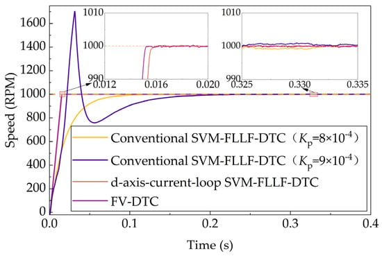
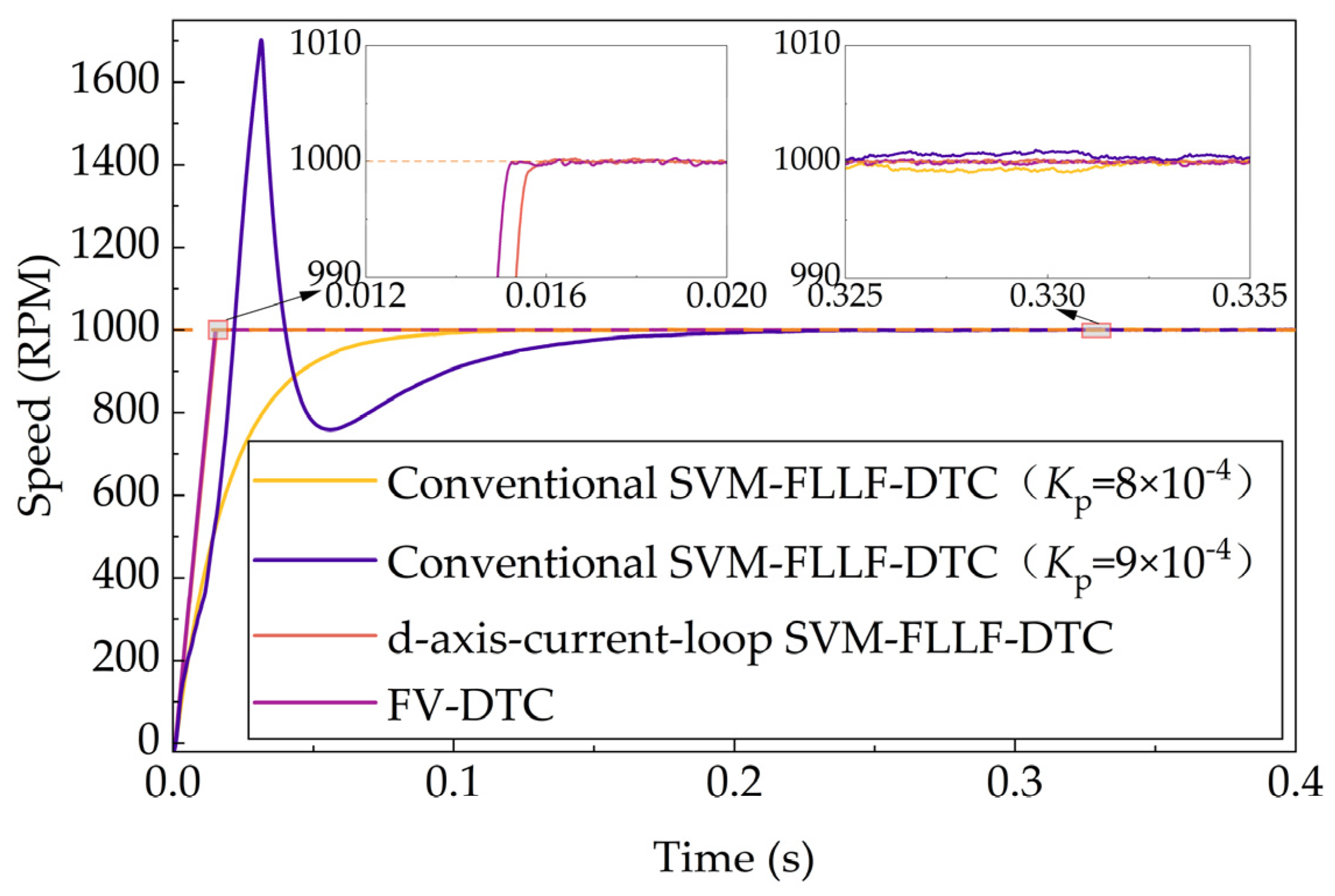
Figure 13 presents the flux-linkage trajectories of the three algorithms under a relatively low flux-linkage limit (0.001144 Wb). It can be observed that all three algorithms effectively constrain the flux-linkage magnitude. However, to ensure the effectiveness of the limiting strategy, the speed-loop control parameters of the conventional SVM-FLLF-DTC are set extremely conservative (Kp = 8 × 10⁻⁴; Ki = 2 × 10⁻²), resulting in an excessively slow speed response that fails to exploit the inherently fast dynamic response of DTC. The speed responses of the three algorithms under this condition are shown in Figure 14.
Figure 14.
Speed responses of the three algorithms under a flux-linkage limit of 0.01144 Wb. The horizontal dashed line represents the reference speed of 1000 rpm.
It can be observed from Figure 14 that both improved algorithms exhibit superior performance, with better dynamic and steady-state characteristics than the conventional algorithm. Meanwhile, the conventional algorithm is extremely unstable and requires a highly conservative control strategy; even a very slight variation in the speed-loop PI parameters may lead to loss of control of the entire system, as illustrated in Figure 15. If the proportional gain is set too large, the q-axis flux-linkage magnitude may exceed the flux-linkage limit. At this point, further reducing the d-axis flux linkage may cause the d-axis flux linkage to reverse its direction relative to the rotor flux linkage, which not only renders the flux-linkage limiting ineffective but also results in loss of speed control, as shown in Figure 15.
Figure 15.
d,q-Axis flux linkage and speed of conventional SVM-FLLF-DTC under loss of control. The dashed lines are used for visual clarity only.
5.3. Experimental Results
This section presents the experimental comparison of the three algorithms, conducted on the HIL platform described in Section 5.1. The base values used in the experiments are as follows: current base Ibase = 11 A, flux-linkage base ψf = 0.011 Wb, and torque base Tbase = 1.24 N·m. The flux-linkage limiting parameters are set to ψsmax = 1.04 p.u. and ψsdmin = 0.2 p.u. The experiments consist of a dynamic performance comparison, including the speed step response from 0 to 500 rpm, the load torque step response from 0 to 0.2 p.u., and the speed step response from 500 to 1000 rpm.
The speed-loop gains used in the experiments are listed in Table 5. The conventional SVM-FLLF-DTC was even configured with the highest proportional gain among the three schemes, while the two improved schemes shared the same lower gains. Thus, no conservative parameter setting was imposed on any scheme in the experiments. The conservative gains mentioned in Section 5.2 apply only to the low-flux-limit simulation, where they are required to keep the conventional scheme marginally stable. The experimental comparison is therefore not biased against the conventional method.
Table 5.
The experimental speed-loop gains of the three schemes.
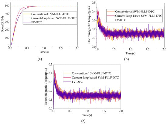
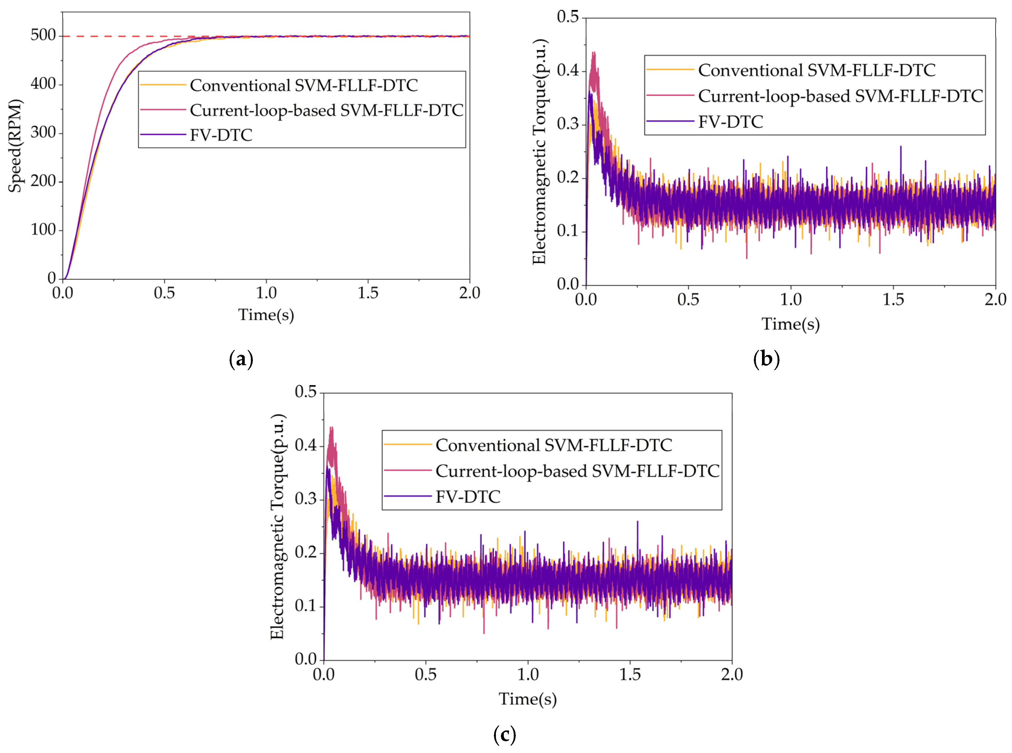
Figure 16 presents the experimental results of the speed step response. As shown in Figure 16a, the d-axis current-loop-based SVM-FLLF-DTC exhibits the fastest speed response, followed by FV-DTC, with the conventional SVM-FLLF-DTC being the slowest; however, the settling times of the three algorithms are comparable. As shown in Figure 16b, FV-DTC achieves the smallest electromagnetic torque ripple, followed by the current-loop-based scheme, whereas the conventional SVM-FLLF-DTC exhibits the most severe torque pulsation. As shown in Figure 16c, the current-loop-based scheme attains the highest flux-linkage tracking accuracy. FV-DTC, owing to its purely proportional flux control, exhibits a minor steady-state flux-linkage error, yet its flux-linkage oscillation amplitude is the smallest among the three. In contrast, the conventional SVM-FLLF-DTC suffers from considerably larger flux-linkage tracking errors and oscillations than both improved schemes. The experimental results demonstrate that FV-DTC, with its structurally simple proportional flux closed-loop architecture, outperforms the two benchmark schemes in torque ripple suppression and flux-linkage smoothness, while its flux-linkage steady-state error remains within an acceptable engineering range. Although the d-axis current-loop-based scheme achieves marginally better speed response and flux-linkage tracking accuracy, these gains come at the expense of retaining the current inner loops and PI regulators. Overall, FV-DTC strikes a favorable balance between structural simplicity and control performance.
Figure 16.
Speed step response from 0 to 500 rpm under no-load condition. (a) Speed (RPM); (b) electromagnetic torque (p.u.); (c) stator flux linkage (p.u.). The horizontal dashed line represents the reference speed of 500 rpm.
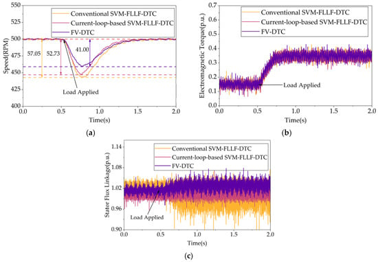
Figure 17 presents the experimental results of the load torque step response from no load to 0.2 p.u. As shown in Figure 17a, under the sudden load application, FV-DTC exhibits the smallest speed drop, followed by the d-axis current-loop-based SVM-FLLF-DTC, whereas the conventional SVM-FLLF-DTC suffers from the most pronounced speed reduction. As shown in Figure 17b, the torque response rates of the three algorithms are comparable, and the relative ranking of the electromagnetic torque ripple amplitude remains consistent with the previous results. As shown in Figure 17c, after the load is applied, the flux-linkage oscillation of all three algorithms increases, yet their relative ranking in terms of oscillation amplitude remains unchanged.
Figure 17.
Load torque step response from 0 to 0.2 p.u. at 500 rpm. (a) Speed (RPM); (b) electromagnetic torque (p.u.); (c) stator flux linkage (p.u.). The red horizontal dashed line represents the reference speed of 500 rpm, and the remaining dashed lines are used for visual clarity only.
The experimental results demonstrate that FV-DTC offers the strongest disturbance rejection capability under sudden load variations, as evidenced by its minimal speed drop, which is attributable to the direct closed-loop regulation of the q-axis flux linkage that eliminates the cascaded delay of current inner loops. The comparable torque response rates across the three algorithms indicate that the load disturbance recovery dynamics are primarily governed by the speed outer-loop bandwidth. Moreover, the relative rankings of torque ripple and flux-linkage oscillation remain invariant across different operating conditions, confirming that these characteristics are inherent to the structural design of each algorithm rather than being operating-point dependent.
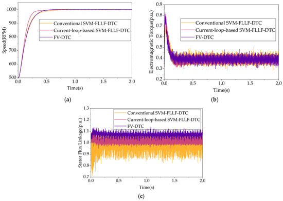
Figure 18 presents the speed step response from 500 to 1000 rpm under load. As shown in Figure 18a, the dynamic tracking capabilities of the three algorithms remain consistent with the low-speed results, with their relative ranking unchanged. As shown in Figure 18b, the torque response rates of the three algorithms are comparable, and the relative ranking of torque ripple remains unchanged. As shown in Figure 18c, as the speed increases, the stator flux-linkage fluctuation of the conventional SVM-FLLF-DTC intensifies, with the instantaneous minimum reaching 0.7ψf, corresponding to a fluctuation amplitude of 0.3ψf. In contrast, the stator flux linkage of FV-DTC remains within a narrow band around ψf, with a significantly smaller fluctuation amplitude; its steady-state error increases slightly with speed but remains acceptable.
Figure 18.
Speed step response from 500 to 1000 rpm under load. (a) Speed (RPM); (b) electromagnetic torque (p.u.); (c) Stator Flux Linkage (p.u.).
To support the conclusions with quantitative evidence, the key performance indicators of the three schemes were evaluated over a 2 s steady-state window, during which the motor was operated at a speed reference of 1000 rpm with a load torque of 0.2 p.u. The torque and flux-linkage signals were sampled at the control frequency of 10 kHz. The torque ripple is quantified by the RMS value of the torque deviation from its mean over this window, defined as:
where Te,avg is the mean torque and N is the number of samples within the window.
The flux-linkage tracking error is quantified by the root-mean-square error (RMSE) between the measured flux linkage and its reference over the same window, defined as:
In addition, the computational burden of each scheme is quantified by the achieved control update rate, defined as the ratio of the number of control updates actually completed to the number of theoretical PWM periods within the window. This metric is meaningful in the present real-time platform, since a heavy algorithm may not complete its computation within every PWM period, which causes the control updates to be partially skipped. The measured indicators are summarized in Table 6.
Table 6.
Quantitative comparison of the three schemes under steady-state operation at 1000 rpm and 0.2 p.u. load.
As shown in Table 5, the proposed FV-DTC achieves the lowest torque ripple RMS and the highest control update rate (100%) among the three schemes, since its computation is always completed within one PWM period. In contrast, the two SVM-FLLF-DTC schemes achieve update rates of only about 75% and 71%. Regarding the flux-linkage tracking RMSE, the d-axis current-loop scheme is the smallest, as expected from its cascaded current regulation; FV-DTC ranks between the current-loop scheme and the conventional one, consistent with its purely proportional flux regulation and the bounded-error analysis in Section 4.2.2. Overall, FV-DTC provides the lowest torque ripple and the best computation efficiency, while the conventional scheme exhibits the largest torque ripple and the worst flux tracking accuracy.
The experimental results demonstrate that the relative performance ranking of the three algorithms remains consistent across a wide speed range, confirming that the torque response and flux-linkage oscillation characteristics are inherently determined by each control structure. The flux-linkage fluctuation in the conventional SVM-FLLF-DTC reaches 0.3ψf at high speed, reflecting the inadequate flux regulation capability of its open-loop d-axis voltage control under field-weakening conditions. FV-DTC effectively suppresses the flux-linkage fluctuation at elevated speeds through the three-scenario scheme.
6. Discussion
To position the proposed method within the broader family of PMSM control strategies, Table 7 provides a qualitative comparison with FOC, classical switching-table DTC, DTC-SVM, and the SVM-FLLF-DTC baseline. FOC and classical DTC represent two distinct control philosophies: FOC regulates the torque indirectly through a cascaded current loop, whereas DTC regulates it directly through the stator flux linkage. The proposed FV-DTC follows the DTC philosophy, since no current loop is employed, while it further replaces the open-loop d-axis voltage channel and the hysteresis or limiting-based flux handling of the conventional DTC family with closed-loop regulation of the dq flux-linkage components. This removes the magnetization effect and the positive-feedback runaway that arise in the SVM-FLLF-DTC baseline, without introducing the structural complexity of FOC. It should be noted that this comparison is qualitative and literature-based; the quantitative comparison in Section 5 is limited to the SVM-FLLF-DTC family, which shares the same flux-vector control framework and therefore provides the most direct evidence of the proposed improvements.
Table 7.
Qualitative comparison of the proposed FV-DTC with FOC and the DTC family.
The experimental results reveal three structural insights into the flux-linkage regulation mechanisms of the compared strategies.
Magnetization effect elimination. In conventional SVM-FLLF-DTC, the d-axis voltage is fixed at zero during normal operation, leaving the d-axis flux linkage under open-loop control. The d,q-axis cross-coupling causes a persistent positive drift in the d-axis current, which adds constructively to the permanent magnet flux, inflating the total stator flux-linkage magnitude well beyond the level required for torque production. This is directly evidenced by the steady-state d-axis flux-linkage magnitude of the conventional scheme, which substantially exceeds that of both improved algorithms (see Section 5.2). FV-DTC resolves this at the structural level by replacing the open-loop d-axis voltage command with a closed-loop proportional flux controller that actively clamps ψsd at ψf. The resulting isd ≈ 0 condition restores the MTPA operating point for the SPMSM, thereby eliminating the magnetization-driven efficiency loss at its root.
Positive-feedback runaway breaking. The three-scenario scheme addresses a deeper problem that the conventional flux-limiting logic cannot handle. When ψsq inadvertently exceeds ψsqmax, the conventional strategy continues to reduce ψsd, crossing zero and reversing its polarity relative to the rotor flux. At this point, the resultant flux magnitude no longer decreases but paradoxically increases, reinforcing the error signal and forming a destructive positive-feedback loop that drives the system to loss of control. The three-scenario scheme identifies this critical condition (Scenario III) and breaks the loop by freezing ψsd at ψsdmin while capping ψsq at ψsqmax, thereby satisfying the flux constraint at the mechanism level without triggering polarity reversal. This explains why FV-DTC maintains stable flux regulation without parameter concessions, whereas the conventional scheme demands extremely conservative speed-loop gains to avoid divergence (see Section 5.2).
Trade-off between FV-DTC and the d-axis current-loop-based scheme. The current-loop-based variant achieves the fastest speed response and the highest flux-linkage tracking accuracy, as expected from its cascaded PI regulation structure. However, these gains come at the cost of retaining the torque inner loop and the d,q-axis current regulation loops, which increases the parameter tuning burden and the overall structural complexity. FV-DTC, with only two proportional flux controllers, delivers nearly equivalent dynamic performance, exhibits the smallest torque ripple and flux-linkage oscillation among the three algorithms, and demonstrates superior load-disturbance rejection and the smallest speed drop under sudden load application, owing to the removal of cascaded inner-loop delays. This represents a deliberate design trade-off: FV-DTC prioritizes structural simplicity and disturbance rejection at the expense of a minor steady-state flux-linkage error.
Sufficiency of proportional control. The theoretical analysis in Section 4.2 established that the flux-to-voltage plant behaves as a pure integrator, forming an inherently stable first-order lag system with zero steady-state error under ideal conditions. The experimental results corroborate this analysis. FV-DTC exhibits a minor steady-state flux error that increases slightly at elevated speeds (500 to 1000 rpm) due to growing stator resistance voltage drop and back-electromotive force disturbances. Nevertheless, this error remains within an acceptable engineering range across the full tested speed envelope, and the system remains overshoot-free, consistent with the first-order lag prediction. Upgrading to a PI controller to eliminate this residual error is straightforward but would introduce overshoot risk and additional tuning complexity.
Structural determinism of performance rankings. Across all tested operating conditions, from low-speed starting to high-speed operation, from no-load to loaded, and through both speed and load transients, the relative rankings of the three algorithms in torque ripple, flux-linkage oscillation, and dynamic response remain invariant. This invariance confirms that these characteristics are structurally determined by each control architecture rather than being operating-point dependent, lending generality to the conclusions drawn from the experimental data.
Several limitations should be noted. First, the validation is restricted to SPMSM drives; extending the strategy to IPMSMs with pronounced saliency (Ld ≠ Lq) would require incorporating the reluctance torque component into the flux-reference generation logic. Second, the d-axis flux-linkage lower bound ψsdmin = 0.2 ψf was selected based on the magnet grade of the motor under test; motors with different permanent magnet materials may require a re-evaluation of this threshold to avoid irreversible demagnetization. Third, all experiments were conducted on an experimental platform; while this provides a controlled environment for reproducing hazardous conditions, physical motor validation under real thermal and mechanical stresses remains necessary to fully assess practical viability.
7. Conclusions
This paper has proposed a flux-vector direct torque control (FV-DTC) strategy for SPMSM drives that structurally resolves two fundamental problems of conventional SVM-FLLF-DTC: the inherent magnetization effect and the positive-feedback runaway embedded in the single-axis flux-linkage limiting scheme. FV-DTC replaces the torque inner loop and open-loop d-axis voltage control with two independent proportional flux controllers, and employs a three-scenario flux-reference generation scheme to adaptively coordinate the d- and q-axis flux constraints. On a DSP-based real-time experimental platform, FV-DTC successfully clamps the d-axis flux linkage at the permanent magnet value, suppresses the flux fluctuation from 0.3 ψf (conventional) to a significantly smaller amplitude without polarity reversal at high speed, and maintains stable flux regulation under a reduced 0.008 Wb flux limit without requiring conservative speed-loop retuning. Among the three compared strategies, FV-DTC achieves the smallest torque ripple and flux-linkage oscillation while exhibiting the strongest load-disturbance rejection, with only a minor and bounded steady-state flux-linkage error attributable to the purely proportional control structure. Future work will extend the strategy to IPMSM drives and investigate a flux-linkage observer with adaptive adjustment of ψsdmin based on online magnet temperature estimation.
Author Contributions
Conceptualization, J.L.; Methodology, J.L.; Software, J.L. and W.Z.; Validation, J.L.; Formal analysis, J.L., Z.C. and P.Z.; Investigation, J.L.; Resources, W.Z., G.Z., E.G., J.M.C. and S.V.; Data curation, J.L. and Z.C.; Writing—original draft, J.L.; Writing—review & editing, J.L., W.Z., P.Z. and S.V.; Visualization, J.L. and Z.C.; Supervision, W.Z., G.Z., E.G., J.M.C., P.Z. and S.V.; Project administration, W.Z., E.G., J.M.C., P.Z. and S.V.; Funding acquisition, W.Z., G.Z. and S.V. All authors have read and agreed to the published version of the manuscript.
Funding
This research received no external funding.
Institutional Review Board Statement
Not applicable.
Informed Consent Statement
Not applicable.
Data Availability Statement
The original contributions presented in this study are included in the article. Further inquiries can be directed to the corresponding author.
Conflicts of Interest
Author Guanghui Zhang was employed by Chongqing Chang’an Wangjiang Industrial Group Co., Ltd. The remaining authors declare that the research was conducted in the absence of any commercial or financial relationships that could be construed as a potential conflict of interest.
Abbreviations
| PMSM | Permanent Magnet Synchronous Motor |
| SPMSM | Surface-Mounted Permanent Magnet Synchronous Motor |
| IPMSM | Interior Permanent Magnet Synchronous Motor |
| DTC | Direct Torque Control |
| FLLF-DTC | Flux-Linkage-Loop-Free Direct Torque Control |
| SVM | Space Vector Modulation |
| SVM-FLLF-DTC | Space-Vector-Modulation-Based Flux-Linkage-Loop-Free Direct Torque Control |
| FV-DTC | Flux-Vector Direct Torque Control |
| FOC | Field-Oriented Control |
| MTPA | Maximum Torque Per Ampere |
| P | Proportional |
| PI | Proportional-Integral |
| DSP | Digital Signal Processor |
| DC | Direct Current |
| PWM | Pulse Width Modulation |
References
- Lin, X.; Liu, J.; Liu, Z.; Gao, Y.; Peretti, L.; Wu, L. Model-Free Current Predictive Control for PMSMs with Ultralocal Model Employing Fixed-Time Observer and Extremum-Seeking Method. IEEE Trans. Power Electron. 2025, 40, 10682–10693. [Google Scholar] [CrossRef] [Scilit]
- Yin, Y.; Liu, L.; Vazquez, S.; Xu, R.; Dong, Z.; Liu, J.; Leon, J.I.; Wu, L.; Franquelo, L.G. Disturbance and Uncertainty Attenuation for Speed Regulation of PMSM Servo System Using Adaptive Optimal Control Strategy. IEEE Trans. Transp. Electrif. 2023, 9, 3410–3420. [Google Scholar] [CrossRef] [Scilit]
- Tavakolian, S.; Fernando Valencia, D.; Fang, G.; Tian, C.; Nahid-Mobarakeh, B. Predictive Direct Torque Control of Switched Reluctance Motor Using Torque Difference Technique with Extended Control Set. IEEE Trans. Transp. Electrif. 2026, 12, 4011–4021. [Google Scholar] [CrossRef] [Scilit]
- Wang, Z.; Chang, S.; Vazquez, S.; Zhang, Z. Adjustable-Order Noise-Resilient Extended State Observer for Model-Free Predictive Speed Control. IEEE Trans. Ind. Electron. 2026. early access. [Google Scholar] [CrossRef] [Scilit]
- Özçiflikçi, O.E.; Koç, M.; Bahçeci, S.; Emiroğlu, S. Overview of PMSM Control Strategies in Electric Vehicles: A Review. Int. J. Dyn. Control 2024, 12, 2093–2107. [Google Scholar] [CrossRef] [Scilit]
- Zhu, P.; Zou, J.; Zhang, W.; Zhai, Y.; Zou, J.; Vazquez, S. Improved Resonant ESO-Based Sampling Delay Error Suppression Method for PMSM Drives Using a Single DC-Link Current Sensor. IEEE Trans. Ind. Electron. 2026, 73, 9692–9704. [Google Scholar] [CrossRef] [Scilit]
- Lian, Y.; Chen, G.; Liu, P. Study of Yaw Moment Control Strategy of Four Wheel Independent Drive Electric Vehicle. Automot. Innov. 2025, 8, 157–168. [Google Scholar] [CrossRef] [Scilit]
- Wang, L.; Yu, Y.; Wang, B.; Zhang, Z.; Jin, S.; Xu, D. Adaptive Dynamic Trajectory Enhancement Strategy for PMSM Field-Weakening Control Based on Operation Profile Constraint. IEEE Trans. Ind. Electron. 2025, 72, 12644–12654. [Google Scholar] [CrossRef] [Scilit]
- Wang, H.; Gan, C.; Ni, K.; Yu, Z.; Qu, R. Virtual Current Constraint Based Segmented Trajectory Control Strategy for Flux-Weakening Operation of SPMSM Drives. IEEE Trans. Power Electron. 2023, 38, 2262–2274. [Google Scholar] [CrossRef] [Scilit]
- Zhang, W.; Zhai, Y.; Zhu, P.; Xu, Y.; Zou, J.; Vazquez, S. Power Regulated Field-Weakening Control Strategy with Adaptive Observers for Permanent Magnet Synchronous Motors. IEEE Trans. Transp. Electrif. 2026. early access. [Google Scholar] [CrossRef] [Scilit]
- Wang, F.; Kong, W.; Wang, Z. Dynamic Flux Weakening-Based DPCC for Rapid Torque Rise of SPMSM Drives at Medium-to-High Speeds. IEEE Trans. Ind. Electron. 2025, 72, 11035–11047. [Google Scholar] [CrossRef] [Scilit]
- Xie, F.; Hu, T.; Wang, L.; Qu, Y.; Yu, X.; Song, Z. Deadbeat Predictive Control Method for PMSM Based on Parallel Anti-Disturbance Structure. J. Electr. Eng. Technol. 2026, 21, 2843–2860. [Google Scholar] [CrossRef] [Scilit]
- Takahashi, I.; Noguchi, T. A New Quick-Response and High-Efficiency Control Strategy of an Induction Motor. IEEE Trans. Ind. Appl. 1986, IA-22, 820–827. [Google Scholar] [CrossRef] [Scilit]
- Depenbrock, M. Direct Self-Control (DSC) of Inverter-Fed Induction Machine. IEEE Trans. Power Electron. 1988, 3, 420–429. [Google Scholar] [CrossRef] [Scilit]
- Sun, D.; Chen, W.; Cheng, Y.; Nian, H. Improved Direct Torque Control for Open-Winding PMSM System Considering Zero-Sequence Current Suppression with Low Switching Frequency. IEEE Trans. Power Electron. 2021, 36, 4440–4451. [Google Scholar] [CrossRef] [Scilit]
- Deng, W.; Li, S. Rotating Sector Switching Table-Based Direct Torque Control of Matrix Converter-Fed PMSM Drives for Common-Mode Voltage Minimisation. IET Power Electron. 2020, 13, 2598–2606. [Google Scholar] [CrossRef] [Scilit]
- Eshwar, K.; Kumar, T.V. Reduction of Torque and Flux Ripples in Direct Torque Control for Three-Level Open-End Winding PMSM Drive. IET Electr. Power Appl. 2020, 14, 2843–2854. [Google Scholar] [CrossRef] [Scilit]
- Hadla, H.; Santos, F. Performance Comparison of Field-Oriented Control, Direct Torque Control, and Model-Predictive Control for SynRMs. Chin. J. Electr. Eng. 2022, 8, 24–37. [Google Scholar] [CrossRef] [Scilit]
- Yang, J.; Hu, Y. Optimal Direct Torque Control of Permanent Magnet Synchronous Motor. Proc. Chin. Soc. Electr. Eng. 2011, 31, 109–115. (In Chinese) [Google Scholar] [CrossRef]
- Gao, J.K. AEKF-Based SVM Flux-Linkage-Loop-Free Direct Torque Control for Permanent Magnet Synchronous Motor. Master’s Thesis, Fuzhou University, Fuzhou, China, 2017. (In Chinese) [Google Scholar]
- Long, J.M.; Sun, Q.; Zhao, C.H. Research on Flux-Linkage-Loop-Free Direct Torque Control Method for Permanent Magnet Synchronous Motor Based on Space Vector Modulation. Electr. Mach. Control Appl. 2016, 43, 44–50. (In Chinese) [Google Scholar]
- Yu, F.-Y.; Li, Z.-C.; Qin, X.-F.; Wang, Y.; Shen, J.-X. Time-Domain Modeling of IPMSM Considering Magnet Eddy Current Reaction Effect and Cross Coupling. IEEE Trans. Energy Convers. 2026, 41, 1279–1290. [Google Scholar] [CrossRef] [Scilit]
- Inoue, Y.; Morimoto, S.; Sanada, M. Mathematical Model of MTPA Control for M- and T-Axis Current Control Systems in PMSM Drives. IEEJ J. Ind. Appl. 2025, 14, 395–401. [Google Scholar] [CrossRef] [Scilit]
- Sun, X.; Xiao, X. Precise Non-Linear Flux Linkage Model for Permanent Magnet Synchronous Motors Based on Current Injection and Bivariate Function Approximation. IET Electr. Power Appl. 2020, 14, 2044–2050. [Google Scholar] [CrossRef] [Scilit]
- Zhao, W.; Wang, N.; Wang, B.; Zhu, G.; Chen, D.; Wang, X. Flux Weakening Control Strategy for Asymmetric Surface Inset Permanent Magnet Synchronous Motors Based on Reoriented dq axis Reference Frame. IEEE Trans. Ind. Electron. 2025, 72, 5658–5668. [Google Scholar] [CrossRef] [Scilit]
- Yang, C.; Song, B.; Jatskevich, J.; Zhang, H.; Lee, C.H.T. Normal-Operation-Undisturbed Magnet Flux Linkage Monitoring in PMSM Drives via a Mechanical-Model-Based Dual Time-Scale Approach. IEEE Trans. Ind. Inform. 2024, 20, 6266–6279. [Google Scholar] [CrossRef] [Scilit]
- Xiao, R.; Peng, S.; Huang, Z.; Chen, G. Deep Flux Weakening Control Strategy for IPMSM with Variable Direct Axis Current Limitations. Electr. Eng. 2022, 104, 3425–3434. [Google Scholar] [CrossRef] [Scilit]
- Barik, L.S.; Misra, H. Dual Side Field Oriented Control of Slip Ring Induction Motor. IEEE Trans. Ind. Electron. 2024, 71, 15404–15414. [Google Scholar] [CrossRef] [Scilit]
- Al-Kaf, H.A.G.; Hakami, S.S.; Lee, K.-B. Hybrid Current Controller for Permanent-Magnet Synchronous Motors Using Robust Switching Techniques. IEEE Trans. Power Electron. 2023, 38, 3711–3724. [Google Scholar] [CrossRef] [Scilit]
- Wang, W.; Liu, C.; Zhao, H.; Song, Z. Improved Deadbeat-Direct Torque and Flux Control for PMSM with Less Computation and Enhanced Robustness. IEEE Trans. Ind. Electron. 2023, 70, 2254–2263. [Google Scholar] [CrossRef] [Scilit]
- Suresh, S.; Rajeevan, P.P. Virtual Space Vector Based Direct Torque Control Schemes for Induction Motor Drives. In Proceedings of the 2018 8th IEEE India International Conference on Power Electronics (IICPE), Jaipur, India, 13–15 December 2018; pp. 1–6. [Google Scholar] [CrossRef] [Scilit]
- Naganathan, P.; Srinivas, S. Direct Torque Control Techniques of Three-Level H-Bridge Inverter Fed Induction Motor for Torque Ripple Reduction at Low Speed Operations. IEEE Trans. Ind. Electron. 2020, 67, 8262–8270. [Google Scholar] [CrossRef] [Scilit]

Disclaimer/Publisher’s Note: The statements, opinions and data contained in all publications are solely those of the individual author(s) and contributor(s) and not of MDPI and/or the editor(s). MDPI and/or the editor(s) disclaim responsibility for any injury to people or property resulting from any ideas, methods, instructions or products referred to in the content. |
© 2026 by the authors. Licensee MDPI, Basel, Switzerland. This article is an open access article distributed under the terms and conditions of the Creative Commons Attribution (CC BY) license.