


Featured Application
The proposed digital workflow enables the rapid development and comparative engineering evaluation of low-cost, subject-specific rehabilitation hand orthoses using commercially available 3D scanning, CAD, FDM, and embedded control technologies. The selected arc-based DC motor-driven actuation mechanism provides a practical and modular foundation for future development of multi-finger rehabilitation orthoses intended for therapist-supervised rehabilitation.
Abstract
Hand rehabilitation orthoses play an important role in restoring upper-limb function in individuals with impaired grasp ability; however, selecting an actuation mechanism that balances functional performance, manufacturing complexity, and production cost remains a significant engineering challenge. This study aimed to develop and compare three low-cost hand and forearm rehabilitation orthosis prototypes within a common subject-specific digital workflow based on three-dimensional (3D) scanning, computer-aided design (CAD), and fused deposition modeling (FDM). Three finger actuation mechanisms—a cable-driven mechanism powered by two DC motors, an arc-based mechanism driven by a DC motor, and an arc-based mechanism driven by a linear actuator—were integrated into subject-specific orthotic structures. The prototypes were evaluated on a single healthy subject by comparing manufacturing time, material consumption, weight, production cost, finger range of motion (ROM), and angular velocity, supplemented by a simplified theoretical mechanical analysis. Prototype 2 achieved the highest total finger ROM (186.66 ± 5.35°) and the greatest angular velocity during extension (177.71 ± 30.03°/s) and flexion (183.16 ± 81.16°/s), while maintaining a low production cost of €18.33. The proposed workflow enabled systematic comparison of the three implemented actuation mechanisms and identified Prototype 2 as providing the most favorable balance between kinematic performance, manufacturing requirements, and practical scalability under the tested conditions. Its simple, modular, and customizable architecture provides a suitable basis for subsequent multi-finger development.
1. Introduction
Restoring hand grasp function is one of the primary goals of rehabilitation for subjects who have experienced stroke, spinal cord injury, or other neurological disorders affecting upper limb motor function. Impaired grasping ability significantly limits a subject’s independence in daily activities, such as object manipulation, personal hygiene, and eating. Intensive and repetitive grasp rehabilitation can contribute not only to the improvement of hand function but also to neurological recovery and the restoration of motor abilities [1,2].
Grasp rehabilitation is based on the repeated execution of finger movements and the training of various grasp patterns. An important part of the therapy is the development of fine motor skills, finger coordination, and the gradual improvement of muscle strength required for object manipulation. Various therapeutic devices are used to support the rehabilitation process, enabling targeted and repeatable finger movements tailored to the individual needs of the user [3].
A limitation of conventional rehabilitation approaches is their frequent dependence on therapist assistance, which may reduce the intensity and frequency of training sessions. For this reason, mechatronic rehabilitation orthoses designed to support finger movements and restore grasp function have gained increasing attention in recent years. These devices provide repetitive, controlled, and task-oriented finger movements to support grasp rehabilitation and activities of daily living.
Current hand rehabilitation devices can generally be divided into rigid, soft, and hybrid exoskeletons [4]. Rigid exoskeletons [5,6] usually consist of articulated mechanical links aligned with the anatomical joints of the fingers. Their main advantage is precise motion guidance and the possibility of generating relatively high assisting forces. However, they may be more complex, heavier, and less comfortable if the mechanical axes are not properly aligned with the user’s finger joints. Examples of such systems include wearable hand exoskeletons for activities of daily living and neurorehabilitation, where flexion and extension of the fingers are actively supported by a compact mechanical structure. More recently, Peperoni et al. [7] investigated an exoskeleton for post-traumatic hand rehabilitation, demonstrating the continued development and clinical evaluation of compact powered mechanical solutions.
Soft robotic gloves [8,9,10,11] represent another important group of rehabilitation devices. These systems often use pneumatic actuators, fabric-based structures, elastomeric elements, or cable-driven mechanisms to assist finger flexion and extension. Their main advantages include adaptability to the hand, reduced risk of joint misalignment, and improved comfort during human–robot interaction. Several studies describe soft pneumatic gloves intended for hand assistance and rehabilitation, including systems with variable stiffness actuators, positive–negative pneumatic actuation, or fabric-based bidirectional actuation. Recent developments in soft robotic rehabilitation have focused particularly on lightweight and compliant bidirectional actuation. Bazina et al. [12] developed a soft robotic rehabilitation glove using pneumatic actuation, while Lim et al. [13] demonstrated a bidirectional fabric-based soft robotic glove capable of assisting hand function in subjects with chronic stroke.
Hybrid designs [14,15,16] combine rigid supporting parts with soft or compliant elements. This approach aims to achieve a compromise between accurate motion transmission and user comfort. Some hybrid hand exoskeletons use 3D-printed structural components together with flexible joints, compliant transmissions, or textile interfaces. Such concepts are particularly suitable for low-cost and subject-specific rehabilitation devices because 3D printing enables rapid prototyping, dimensional adaptation to the user’s hand, and relatively simple replacement of damaged parts.
The actuation of hand orthoses is commonly achieved using DC motors, servo motors, pneumatic actuators, or tendon/cable-driven transmissions [4,8,10,17]. Cable-driven systems allow the actuator to be placed on the forearm or outside the hand, reducing the weight directly applied to the fingers. Pneumatic systems provide compliant interaction and are frequently used in soft robotic gloves, but they may require additional air supply components. Electrically driven systems with motors and linear mechanisms are attractive for compact and low-cost devices, especially when combined with additive manufacturing and simple embedded control electronics.
Different control strategies have also been investigated. Some devices perform predefined passive rehabilitation trajectories, while others use user-intention detection based on biosignals. Electromyography (EMG) based control allows the orthosis to respond to residual muscle activity, which may increase user engagement during therapy. Similar approaches include force-myography (FMG), where muscle deformation is detected mechanically, and brain–computer interface (BCI) or electroencephalography (EEG)-based control, which can be useful for subjects with limited voluntary muscle activation [6,15,18,19,20]. Bilateral training strategies, where the movement of the affected hand is guided by signals obtained from the healthy hand, have also been proposed [18]. More recent studies have further demonstrated the potential of myoelectric control for hand rehabilitation systems. Cisnal et al. [21] investigated EMG-driven bilateral therapy using a hand rehabilitation exoskeleton and evaluated the influence of visual biofeedback on user performance, while Ullah et al. [22] developed and tested the ExoMechHand prototype using EMG signals for intention-based hand rehabilitation.
Beyond direct intention-based control, recent research has also investigated adaptive assistance strategies. Sun et al. [23] proposed an assist-as-needed control approach for a soft robotic glove that combines myoelectric information with human–object contact estimation to adapt assistance during grasping tasks.
Although many published systems demonstrate promising results, several limitations remain. Many devices are still relatively expensive, mechanically complex, or difficult to customize for individual users. Some systems require external pneumatic equipment or specialized laboratory hardware, which limits their use in home-based rehabilitation. Therefore, there is still a need for low-cost, lightweight, and subject-specific hand orthoses that can support repeated grasp rehabilitation while remaining simple to manufacture and operate. Most previous studies describe the development and evaluation of a single device or actuation architecture. Direct comparisons between alternative actuation mechanisms are therefore difficult because differences in orthotic geometry, manufacturing methods, control architectures, and experimental protocols introduce additional variability. Relatively few studies combine subject-specific 3D scanning, CAD (Computer Aided Design), additive manufacturing (AM), and comparative evaluation of different actuation mechanisms within a common development workflow. Consequently, engineering evidence supporting the selection of an appropriate actuation mechanism for subject-specific rehabilitation orthoses remains limited.
The present study addresses this gap by developing and comparing low-cost rehabilitation hand and forearm orthosis prototypes within a common subject-specific digital workflow based on 3D scanning, CAD, and AM. Three actuation mechanisms were evaluated: a cable-driven mechanism powered by two DC motors, an arc-based mechanism driven by a DC motor, and an arc-based mechanism driven by a linear actuator. The developed prototypes were compared in terms of manufacturing characteristics, finger range of motion (ROM), angular velocity, and theoretical mechanical performance. The principal methodological contribution is the systematic comparison of three implemented actuation mechanisms within the same subject-specific development framework, thereby reducing variability associated with orthotic geometry, manufacturing, and experimental conditions. The comparison was used to identify a suitable actuation mechanism for subsequent development of a multi-finger rehabilitation orthosis.
2. Materials and Methods
The developed device can be classified as a rigid rehabilitation hand orthosis. Its primary load-bearing structure consists of a subject-specific orthotic framework and functional components manufactured using AM. The orthosis was designed to be operated by a rehabilitation therapist who supervises and controls the rehabilitation process. Finger movements are controlled through an external handheld controller equipped with pressure sensors. By applying pressure to individual sensors, the therapist can activate the corresponding finger movement through the integrated control system.
To evaluate the proposed actuation mechanisms, several prototype variants were developed and experimentally assessed. The initial evaluation was limited to the index finger to verify the mechanical functionality and integration feasibility of the proposed mechanisms while enabling their comparison under consistent experimental conditions. Based on the experimental results, the most suitable mechanism was selected for subsequent development toward a multi-finger rehabilitation orthosis.
The developed prototypes were experimentally evaluated on a single healthy subject. Informed consent was obtained from the subject involved in the study, and the study was approved by the Institutional Ethics Committee of the Technical University of Košice under protocol No. 29798/2020.
2.1. Study Design
The development of the proposed rehabilitation orthosis followed a personalized design workflow consisting of anatomical data acquisition, concept development, computer-aided design, additive manufacturing, prototype assembly, and experimental evaluation. The overall development workflow comprised the following stages:
- development of alternative finger actuation mechanisms,
- design of the corresponding actuation and control components,
- CAD development, additive manufacturing, and assembly of prototype actuation mechanisms,
- development and fabrication of subject-specific orthosis prototypes with integrated actuation and control components based on 3D scanning data,
- experimental evaluation of finger flexion and extension performance through range of motion (ROM) and angular velocity measurements.
2.2. Design of the Finger Flexion and Extension Mechanisms
Two alternative actuation mechanisms were developed as part of the active orthosis design to provide assisted finger flexion and extension. Both mechanisms were designed to enable controlled finger motion while maintaining low weight and allowing integration into a subject-specific 3D-printed orthotic structure.
2.2.1. Cable-Driven Mechanism
The first mechanism uses a dual-cable actuation system routed along the finger (Figure 1A). A cable positioned on the palmar side of the finger generates flexion, while a second cable routed along the dorsal side generates extension. Both cables pass through three orthotic rings located on the proximal, middle, and distal phalanges of the index finger. These rings serve as cable guides while allowing movement of the finger joints. When tension is applied to the palmar cable, a flexion moment is generated across the finger segments, resulting in flexion at the metacarpophalangeal (MCP), proximal interphalangeal (PIP), and distal interphalangeal (DIP) joints. Conversely, tension applied to the dorsal cable generates an opposing moment, producing finger extension. The mechanism operates similarly to a tendon-driven system, in which controlled cable displacement produces finger flexion and extension.
Figure 1.
Conceptual designs of the proposed finger actuation mechanisms: (A) cable-driven mechanism using palmar and dorsal cables routed through three orthotic rings; (B) arc-based mechanism using a dorsally positioned arc driven by a proximal linear mechanism.
2.2.2. Arc-Based Mechanism
The second mechanism uses an arc-shaped component positioned along the dorsal side of the finger (Figure 1B). The proximal end of the arc is connected to a hinge located above the metacarpophalangeal (MCP) joint, while the distal end is attached through a second hinge to an orthotic ring positioned on the distal phalanx. The arc-shaped component is actuated by a linear drive mechanism located in the proximal dorsal region of the hand. Linear displacement of the drive mechanism in the proximal-distal direction induces rotation of the arc. Rotation of the arc toward the finger produces flexion of the finger joints. Movement in the opposite direction returns the arc toward its initial position and produces extension. The hinged connections at both ends of the arc enable transmission of motion while accommodating the changing position of the finger during flexion and extension.
2.3. Actuation and Control System Design
The actuation and control systems were developed to provide controlled finger flexion and extension of the rehabilitation orthosis. Three alternative actuation mechanisms were implemented and evaluated, differing in their methods of motion generation and transmission.
2.3.1. Cable-Driven DC Motor Actuation System Design (Prototype 1)
In the first prototype, the orthosis was secured to the forearm and hand, with two cables routed along the palmar and dorsal sides of the index finger through ring-shaped orthotic components (Figure 1A). The palmar cable generated finger flexion, while the dorsal cable generated extension. Each cable was actuated independently by a geared DC motor powered by a battery (Figure 2). The system was controlled using an Arduino Nano microcontroller (Arduino S.r.l., Monza, Italy), with motor speed regulated via H-bridges according to input from a pressure sensor.
Figure 2.
Electrical schematic of Prototype 1 (AN—Arduino Nano, B—battery, HB—H-bridge, MTR—DC motor, TEN—pressure sensor).
The system was powered by a 6 V, 1.5 Ah battery that supplied the microcontroller, sensors, and motors. An Arduino Nano microcontroller processes the pressure sensor input and generates control signals for two H-bridges, one for each motor. The H-bridges enabled bidirectional motor rotation, allowing the corresponding cables to be pulled or released during finger movement.
The FIT0484 DC motors had a current consumption of 0.17 A and a maximum torque of 215 mNm and were equipped with gearboxes to provide the required torque. One motor actuated finger flexion, while the other actuated extension. Movement was controlled using a 1000 MG pressure sensor connected to an analog input on the Arduino. The sensor signal determined motor activation and speed, with increasing applied pressure resulting in a higher motor speed.
During operation, pressure applied to the sensor was processed by the Arduino Nano, which activated the H-bridge using pulse-width modulation (PWM). The activated motor pulled the respective cable to generate finger flexion or extension, while the opposing cable released as required. This configuration enabled independent control of finger movements, with motor speed regulated proportionally according to the applied pressure.
2.3.2. Arc-Based DC Motor Actuation System Design (Prototype 2)
The second prototype employed an arc-based finger actuation mechanism (Figure 1B) driven by a single geared DC motor. Unlike the cable-driven design, the motor did not actuate the finger through palmar and dorsal cables. Instead, motor rotation was converted into linear displacement by a custom-designed linear drive component integrated into the orthotic structure. This displacement was transferred to the arc component positioned on the dorsal side of the finger, generating finger flexion or extension depending on the direction of motor rotation.
The control architecture was based on the same electronic platform as that used for Prototype 1. The system consisted of an Arduino Nano microcontroller, a pressure sensor, an H-bridge motor driver, a 6 V battery, and a DC motor (Figure 3). The pressure sensor provided an analog input that was processed by the microcontroller to regulate the direction and speed of the motor rotation. Motor speed was controlled using PWM, with the applied pressure determining the motor speed. Bidirectional motor rotation enabled the linear drive mechanism to move in both directions, thereby generating finger flexion and extension through the arc-based mechanism.
Figure 3.
Electrical schematic of Prototype 2 (AN—Arduino Nano, B—battery, HB—H-bridge, MTR—DC motor, TEN—pressure sensor).
The developed actuation system (Figure 4) enables bidirectional control of finger flexion and extension through a single DC motor.
Figure 4.
Physical implementation of the electronic control system for Prototype 1 and 2 showing the Arduino Nano (1), H-bridge (2), pressure sensor (3), battery (4), and DC motor (5).
2.3.3. Arc-Based Linear Actuator Control System Design (Prototype 3)
The third prototype used the same arc-based finger mechanism as Prototype 2; however, the custom linear drive and DC motor assembly were replaced with a commercial 12 V linear actuator (Zhejiang Hoodland Technology Co., Ltd., Wenzhou, China) (Figure 5). The actuator had a stroke length of 30 mm, a linear speed of 4 mm/s, and a maximum force of 146.80 N.
Figure 5.
Linear actuator used for Prototype 3 (1—fully retracted, 2—fully extended).
The actuator was directly connected to the proximal end of the arc component and generated translational motion along its axis. This motion was transferred to the arc, producing finger flexion and extension through rotation of the arc component.
In contrast to Prototypes 1 and 2, the linear actuator was not integrated with the Arduino-based control system. The actuator was operated using ON/OFF electrical control, resulting in either full extension or full retraction of its 30 mm stroke.
2.4. Control Software Development
The control software for the rehabilitation orthosis prototypes was developed using embedded C++ programming on an Arduino Nano microcontroller platform. The software was designed to control the DC motor-based actuation mechanisms implemented in Prototypes 1 and 2. Its primary function was to acquire analog signals from force-sensitive sensors, process the measured values, and generate control signals for the motor drivers controlling finger flexion and extension.
The control system was designed to be operated by a rehabilitation therapist through a handheld controller equipped with force-sensitive sensors. The applied pressure was converted into motor commands, enabling proportional control of the actuation mechanisms. The software continuously monitored the sensor outputs and adjusted motor operation according to the applied pressure.
Motor control was implemented using PWM, enabling proportional speed regulation. Bidirectional motor operation was achieved through H-bridge motor drivers, allowing the actuation mechanisms to perform both flexion and extension movements. To prevent unintended activation caused by electrical noise or low sensor readings, a threshold-based activation strategy was implemented. Only sensor values exceeding a predefined threshold were considered valid control inputs. Valid sensor values were mapped to a predefined PWM output range to regulate motor speed proportionally to the applied pressure. Figure 6 summarizes the implemented control algorithm.
Figure 6.
Flowchart of the pressure-sensor-based control algorithm implemented on the Arduino Nano microcontroller.
For Prototype 2, the same control architecture was used. The software controlled a single DC motor driving the linear transmission connected to the arc-based mechanism. PWM-based speed regulation and force-sensitive sensor control were retained, enabling proportional regulation of motor speed according to the applied pressure.
The developed control software provided the following functionality:
- PWM-based motor speed regulation for smooth and proportional control;
- bidirectional motor control using H-bridge drivers;
- threshold-based activation to prevent unintended motor activation;
- independent control of flexion and extension actuators in Prototype 1;
- proportional motor speed regulation in Prototype 2;
- adjustable motor speed profiles to compensate for differences in mechanical transmission characteristics.
Unlike Prototypes 1 and 2, Prototype 3 employed a commercial linear actuator that was not integrated with the Arduino-based control system during the preliminary evaluation stage. The actuator was operated using direct ON/OFF electrical control, allowing movement only between its fully extended and fully retracted positions.
2.5. Development of Experimental Prototype Mechanisms
To experimentally evaluate the proposed finger flexion and extension actuation concepts, a series of prototype mechanisms were designed, manufactured, assembled, and tested. The development process included CAD design of the individual mechanical components, AM, assembly of the prototype mechanisms, and experimental verification of their functionality.
The CAD design stage included all structural and functional components required for each prototype, including gearbox housings, cable-guiding elements, orthotic rings, arc-shaped components, hinge joints, motor mounting elements, and linear transmission components. The geometry of these components was adapted to the requirements of each actuation mechanism and its integration into the rehabilitation orthosis. All components were designed using SolidWorks (Version 2025 SP0.0, Dassault Systèmes SolidWorks Corp., Waltham, MA, USA) CAD software.
The CAD models were exported as STL files and processed using Bambu Studio (Shenzhen Tuozhu Technology Co., Ltd., Shenzhen, China) slicing software prior to fabrication. All prototype components were manufactured from polylactic acid (PLA) using a Bambu Lab A1 (Shenzhen Tuozhu Technology Co., Ltd., Shenzhen, China) fused deposition modeling (FDM) printer. The printing parameters were set to the default values recommended for the specific printer and slicing software. Following fabrication, the individual parts were assembled into functional prototype mechanisms and integrated with the corresponding actuation and control components.
The assembled prototypes were experimentally evaluated to verify their ability to generate finger flexion and extension. The evaluation focused on the functionality of the actuation mechanisms, motion transmission, and their potential for integration into a future multi-finger rehabilitation orthosis.
2.5.1. Cable-Driven Mechanism Prototype
The first experimental prototype was developed to verify the functionality of the proposed cable-driven finger actuation mechanism. The prototype (Figure 7) was designed to actuate a single finger and consisted of a gearbox housing, a linear cable-driving component, cable guiding elements, and a mechanical finger model representing the finger joints. The prototype used two independently controlled DC motors positioned within the prototype structure. One motor controlled finger flexion, while the other controlled finger extension. Motion was transmitted through separate cables routed along the palmar and dorsal sides of the finger.
Figure 7.
Design of the cable-driven mechanism prototype.
To ensure effective force transmission, the linear cable-driving component was designed as a rigid element mechanically connected to the gearbox mechanism. The gearbox housing incorporated dedicated mounting features to secure the DC motors and maintain alignment between the motor gears and the linear transmission mechanism. The printed parts were subsequently assembled with the DC motors, gearbox components, cables, and electronic control components to create a functional prototype for experimental evaluation (Figure 8). The assembled prototype was evaluated with respect to motion transmission, mechanical stability, cable guidance, and overall feasibility of the proposed actuation mechanism.
Figure 8.
Assembled cable-driven prototype used for experimental evaluation (1—full extension, 2—full flexion).
2.5.2. Arc-Based Mechanism Prototype Driven by a DC Motor
The second experimental prototype was developed to verify the functionality of the proposed arc-based finger actuation mechanism driven by a DC motor. The prototype was assembled on a rigid polymer base plate that supported mechanical components and facilitated preliminary evaluation of the mechanism.
The mechanism (Figure 9) consisted of two hinge joints mounted on the base plate. The first hinge supported the gearbox assembly and DC motor, while the second hinge connected the arc-shaped component to the base plate. A gear mounted on the DC motor shaft converted motor rotation into linear displacement of a custom-designed transmission component. The distal end of the linear transmission component was connected to the arc-shaped component through an additional hinge joint.
Figure 9.
Design of the arc-based mechanism prototype driven by a DC motor.
This configuration allowed motor-generated translational motion to be transferred to the arc component while accommodating changes in its orientation during movement (Figure 10).
Figure 10.
Assembled arc-based mechanism driven by a DC motor used for experimental evaluation (1—full extension, 2—full flexion).
During operation, the linear transmission component pushed or pulled the proximal end of the arc component, causing the arc to rotate about its hinge joint. The direction of motor rotation determined whether the mechanism generated finger flexion or extension. The evaluation focused on mechanical stability, motion transmission, and the ability of the mechanism to generate flexion and extension through linear displacement.
2.5.3. Arc-Based Mechanism Prototype Driven by a Linear Actuator
The third experimental prototype was developed to evaluate the functionality of the proposed arc-based finger actuation mechanism driven directly by a linear actuator. Like Prototype 2, the mechanism was assembled on a rigid polymer base plate that supported the mechanical components and facilitated preliminary evaluation of the mechanism. The mechanism (Figure 11) consisted of a linear actuator, an arc-shaped component, and hinge joints connecting the individual components.
Figure 11.
Design of the arc-based mechanism prototype driven by a linear actuator.
The proximal end of the linear actuator was attached to the base plate through a hinge joint, allowing limited rotational movement during operation. The distal end of the actuator rod was connected to the arc-shaped component using a second hinge joint. The arc component was connected to the base plate through an additional hinge joint positioned distal to the actuator attachment point. This arrangement (Figure 12) enabled direct transmission of the actuator stroke to the arc-shaped component without intermediate transmission elements, such as a gearbox or a linear conversion mechanism. As the actuator rod extended or retracted, the arc component rotated about its proximal hinge joint. The direction of actuator movement determined whether the mechanism generated flexion or extension. The evaluation focused on mechanical stability, motion transmission, and the ability of the mechanism to generate finger flexion and extension through direct linear displacement.
Figure 12.
Assembled arc-based mechanism driven by a linear actuator used for experimental evaluation (1—full extension, 2—full flexion).
2.6. Development of Orthosis Prototypes with Integrated Actuation and Control Mechanisms
Following the experimental verification of the individual actuation mechanism, three rehabilitation orthosis prototypes were developed to evaluate their integration into a subject-specific hand and forearm orthotic structure. The objective of this stage was to assess the feasibility of incorporating the actuation and control components into the wearable orthosis and to evaluate their ability to generate controlled flexion and extension of the index finger.
The development process included CAD design of subject-specific orthotic structures based on 3D-scanned anatomical data, AM of the orthotic and auxiliary components, prototype assembly, and experimental evaluation on a single healthy subject.
2.6.1. Design of Orthosis Prototypes
Three subject-specific hand and forearm orthosis prototypes were designed using free-form CAD software based on a 3D scan of the subject’s upper limb and were subsequently manufactured using FDM technology. The geometry of each orthosis was adapted to the anatomical shape of the hand and forearm to ensure appropriate fit and stable positioning during experimental evaluation.
The 3D scan of the hand and forearm (Figure 13) was acquired using an Artec Eva (Artec 3D, Luxembourg, Luxembourg) handheld optical 3D scanner. The scanning frequency was set to 16 frames per second (fps), and color texture acquisition was enabled. The upper limb was positioned according to a standardized scanning procedure to obtain the anatomical data required for subject-specific orthosis design. The scanned segment included the hand, wrist, and distal forearm. During scanning, the upper limb was maintained in a stable position with the dorsal side of the hand facing upward. The wrist was positioned in approximately 10–20° of extension, and the thumb was positioned in opposition to the other fingers. The fingers were maintained in a relaxed position without pronounced flexion or extension. The forearm was oriented to enable acquisition of both the dorsal and radial aspects of the hand. This position was maintained throughout scanning to minimize motion artifacts and obtain complete anatomical data for further processing [24].
Figure 13.
Acquired 3D scan of the test subject’s hand and forearm from the dorsal (upper) and palmar (lower) view.
The primary orthotic structures (Figure 14) were designed using Meshmixer (Autodesk, Inc., San Francisco, CA, USA) CAD software. The design process began with boundary curves defining the required shape and coverage of the orthosis over the hand and forearm. The selected surface regions were extracted from the scanned model with a uniform 1 mm offset between the skin and the inner orthotic surface. This offset was applied to facilitate donning and doffing and compensate for minor inaccuracies associated with the 3D scanning and AM. Following surface extraction, the orthotic shell was generated by applying a 2 mm outward extrusion, defining the final wall thickness. Additional mounting platforms, fastening features, and interfaces were incorporated according to the requirements of each prototype and its actuation and control components.
Figure 14.
Individual orthosis CAD prototypes (1—cable-driven mechanism, 2—arc-based mechanism driven by a DC motor, 3—arc-based mechanism driven by a linear actuator).
2.6.2. Orthosis Prototypes Manufacturing and Assembly
The CAD models of the orthosis prototypes were exported as STL files and processed using Bambu Studio (Shenzhen Tuozhu Technology Co., Ltd., Shenzhen, China) slicing software prior to fabrication. All orthosis prototypes were manufactured from PLA filament using a Bambu Lab A1 (Shenzhen Tuozhu Technology Co., Ltd., Shenzhen, China) FDM printer. The printing parameters were set according to the default settings recommended for the printer and slicing software. Following fabrication, support structures were removed and the printed orthotic components were post-processed and prepared for assembly. The corresponding actuation mechanisms, control components, and fastening elements were then integrated into each orthosis to produce the fully assembled prototypes for experimental evaluation (Figure 15).
Figure 15.
Fully assembled rehabilitation orthosis prototypes for experimental evaluation (1—cable-driven mechanism, 2—arc-based mechanism driven by a DC motor, 3—arc-based mechanism driven by a linear actuator).
The number of printed parts, AM time, material consumption (including support structures), total prototype weight, and production cost (including the individual actuation components) were recorded for each prototype.
2.7. Experimental Evaluation of Developed Orthosis Prototypes
The assembled orthosis prototypes were applied to the hand of a single healthy subject (Figure 16). Experimental testing focused on the index finger, which was selected as a representative finger for evaluating the functionality of the proposed actuation mechanisms. For each prototype, the ability to generate finger flexion and extension was evaluated. The preliminary functional assessment also considered mechanical stability, motion transmission, and the interaction between the orthotic structure and the actuation mechanism.
Figure 16.
Individual orthosis prototypes applied to the hand of the test subject.
2.7.1. Range of Motion Measurement
Range of motion (ROM) analysis was performed to quantify the ability of each orthosis prototype to generate flexion and extension of the index finger. The evaluation was carried out on a single healthy subject, with each prototype applied to the hand according to its intended wearing position. The index finger was selected for the preliminary functional assessment because of its important role in functional grasping and its suitability for evaluating finger flexion and extension during engineering validation. Evaluating a single finger reduced experimental complexity and enabled direct comparison of the three actuation mechanisms under identical conditions before development of a multi-finger orthosis.
For each prototype, the finger was recorded in two positions: the initial extended position and the maximum flexed position achieved by the actuation mechanism. Images were acquired from the lateral side of the hand to visualize finger motion in the sagittal plane. The camera was positioned perpendicular to the plane of finger movement to minimize perspective distortion. The hand and forearm were maintained in a stable position throughout image acquisition.
Joint angles were measured from digital images using ImageJ software (Version 1.54g, National Institutes of Health, Bethesda, MD, USA) (Figure 17). Image-based assessment has previously been applied to the quantitative evaluation of joint ROM [25]. Anatomical landmarks corresponding to the carpal bone, metacarpophalangeal (MCP), proximal interphalangeal (PIP), and distal interphalangeal (DIP) joints were identified on the hand and index finger. For each joint, the angle was defined as the included angle between the longitudinal axes of two adjacent anatomical segments. Specifically, the MCP angle was measured between the longitudinal axes of the metacarpal and proximal phalanx, the PIP angle between the proximal and middle phalanges, and the DIP angle between the middle and distal phalanges. All measurements were performed using the Angle Tool in ImageJ.
Figure 17.
Example of a PIP joint angle measurement in ImageJ software.
Each joint angle was measured in three consecutive repetitions (M1–M3) for every prototype and movement position. Three repetitions were selected as a preliminary assessment of measurement repeatability maintaining a consistent experimental protocol across the three prototype configurations. Given the limited number of repetitions, inferential statistical analysis was not performed. The mean and standard deviation (SD) were calculated from the three repeated measurements and are reported in Table 1. The repeated measurements characterize measurement repeatability and do not represent independent biological replicates.
Table 1.
Joint angle measurements for the three orthosis prototypes, including repeated measurements (M1–M3) and mean ± SD values.
The angular displacement of each joint was calculated separately for the three repetitions (M1–M3) as the difference between the flexion and extension joint angles. In cases where the MCP joint was positioned in hyperextension, the hyperextension angle was included in the calculation of MCP ROM. The total finger ROM (1) was calculated separately for each repetition as the sum of the angular displacements of the MCP, PIP, and DIP joints according to:
ROMtotal = ROMMCP + ROMPIP + ROMDIP,
The resulting joint ROM and total finger ROM values from the three repetitions were used to calculate the mean and SD for each prototype.
2.7.2. Angular Velocity Measurement
In addition to ROM analysis, the dynamic performance of the developed orthosis prototypes was evaluated using the average angular velocity (2) of finger movement. Average angular velocity was then calculated according to:
where ωavg is the average angular velocity (°/s), ROMtotal is the total measured angular displacement (°), and t is the movement duration (s).
ωavg = ROMtotal/t,
The analysis was performed to quantify the speed of finger flexion and extension generated by each actuation mechanism. The measurements were based on video recordings acquired during experimental testing of the orthosis prototypes. All recordings were captured under identical conditions with a fixed camera position and a constant frame rate. The videos were subsequently analyzed using Kinovea software (version 2025.2, Kinovea Open-Source Project, Bordeaux, France), allowing frame-by-frame identification of the onset and termination of finger movement.
For each prototype, the duration of finger flexion and extension was determined as the time interval between the initial and final positions of the index finger. Three consecutive repetitions were analyzed for each movement direction (Table 2). The corresponding total angular displacement was obtained separately for each repetition from the performed ROM analysis described in Section 2.7.1.
Table 2.
Measured movement duration of index finger flexion and extension used for angular velocity analysis. Values are presented as individual measurements and mean ± SD (n = 3).
Angular velocity was calculated separately for each of the three repetitions of flexion and extension using Equation (2), with the total ROM and movement duration from the corresponding repetition. The resulting angular velocity values were used to calculate the mean and SD for each movement direction. ROM, movement duration, and angular velocity were reported as mean ± SD based on three repetitions (n = 3). Because these repetitions represented repeated technical measurements obtained from a single subject under identical experimental conditions rather than independent biological observations, only descriptive statistics were applied, and no inferential statistical tests were performed.
2.7.3. Simplified Mechanical Analysis of the Actuation Mechanisms
A simplified theoretical mechanical analysis was performed to estimate the force-transmission characteristics of the three actuation systems. The calculations were based on the nominal actuator specifications and geometric parameters of the implemented mechanisms. The analysis was intended to provide first-order theoretical estimates for comparison of the actuation concepts rather than experimentally validated output forces. Unless otherwise specified, transmission losses associated with friction, mechanical compliance, and component deformation were neglected.
Prototype 1—Cable-driven mechanism
For Prototype 1, the theoretical maximum cable tension was estimated from the maximum gearbox output torque of the FIT0484 DC motor and the pitch radius of the GT2 pulley driving the linear carriage. According to the manufacturer, the maximum gearbox output torque of the motor is 0.215 Nm. A 20-tooth GT2 pulley with a belt pitch of 2.00 mm was used, corresponding to a pitch radius of 6.37 mm. The theoretical tangential force transmitted to the GT2 belt was calculated according to:
where FP1 is the theoretical tangential force (N), Tm is the maximum gearbox output torque of the DC motor (N·m), and rp is the pitch radius of the GT2 pulley (m). The pulley pitch radius was determined from the number of pulley teeth and belt pitch according to:
where Nt is the number of pulley teeth and p is the GT2 belt pitch. For Nt = 20.00 and p = 2.00 mm, the calculated pitch radius was 6.37 mm. Substitution into Equation (3) resulted in an ideal maximum tangential force of 33.80 N. Because the belt-driven linear carriage was mechanically connected to the actuation cable, this force was considered an ideal upper-bound estimate of the cable tension. The palmar and dorsal actuation mechanisms employed identical motors and GT2 transmission components; therefore, the same theoretical maximum cable tension was considered for flexion and extension.
FP1 = Tm/rp,
rp = Ntp/2π,
Prototype 2—arc-based DC motor mechanism
For Prototype 2, the theoretical force transmitted by the actuation mechanism was estimated using the same approach as for Prototype 1. The mechanism employed the same FIT0484 geared DC motor and 20-tooth GT2 driving pulley. The rotational motion of the motor was converted into translational displacement of a rigid linear component, which was connected distally to the arc-shaped component through a hinge joint (Figure 18). Both the motor gearbox assembly and the arc-shaped component were hinge-mounted to the orthosis base, allowing their relative orientation to change during movement.
Figure 18.
Geometry of the Prototype 2 arc-based DC motor actuation mechanism used for simplified theoretical mechanical analysis.
Because the motor and GT2 transmission parameters were identical to those of Prototype 1, the theoretical maximum translational force was calculated according to Equation (3). Based on the maximum gearbox output torque of 0.215 Nm and the GT2 pulley pitch radius of 6.37 mm, the theoretical maximum translational force was 33.80 N. Assuming ideal transmission through the rigid linear component, this value represents the theoretical upper-bound force acting at the hinge connection between the linear and arc-shaped components. The theoretical moment acting on the arc-shaped component about its base hinge was subsequently estimated according to:
where MP2 is the theoretical moment acting on the arc-shaped component (Nm), FP2 is the theoretical translational force (N), and d⊥ is the perpendicular distance between the arc base hinge and the line of action of the translational force (m). As shown in Figure 18, the distance between the arc base hinge and the hinge connecting the linear component to the arc was 18.16 mm. In the illustrated mechanism configuration, the corresponding perpendicular moment arm relative to the line of action of the linear component was 13.50 mm. Therefore, the theoretical moment was calculated as:
MP2 = FP2d⊥,
MP2 = 33.80 × 0.0135 ≈ 0.46 Nm
Prototype 3—arc-based linear actuator mechanism
For Prototype 3, the arc-shaped component was actuated directly by a commercial 12 V linear actuator with a nominal force capacity of 14.97 kgf and a stroke length of 30 mm. The proximal end of the actuator was hinge-mounted to the orthosis base, while the distal end of the actuator rod was connected directly to the arc-shaped component through a second hinge joint (Figure 19). Unlike Prototype 2, no intermediate motor-driven linear transmission mechanism was required, and the actuator force was therefore transmitted directly to the arc mechanism.
Figure 19.
Geometry of the Prototype 3 arc-based linear actuator mechanism used for simplified theoretical mechanical analysis.
The manufacturer’s specified force capacity of 14.97 kgf corresponds to approximately 146.80 N. This value was used as the theoretical maximum linear force FP3 generated by the actuator. The corresponding moment acting on the arc-shaped component about its base hinge was estimated according to Equation (5), where MP3 is the theoretical moment acting on the arc-shaped component (Nm), FP3 is the nominal maximum linear actuator force (N), and d⊥ is the perpendicular distance between the arc base hinge and the line of action of the actuator force (m). As shown in Figure 19, the distance between the arc base hinge and the actuator–arc hinge was 16.40 mm, while the perpendicular moment arm in the illustrated mechanism configuration was 13.62 mm. Therefore, the theoretical moment was calculated as:
MP3 = 146.80 × 0.0136 ≈ 2.00 Nm
3. Results
3.1. Manufacturing Evaluation
The manufacturing characteristics of the developed orthosis prototypes are summarized in Table 3. The evaluated parameters included the number of printed parts, AM time, material consumption, total prototype weight, AM production cost, and total prototype cost, including the integrated actuation and control components.
Table 3.
Manufacturing characteristics of the developed orthosis prototypes, including AM time, material consumption, total weight, and production cost.
Prototype 1 required the largest number of printed components (10 parts), resulting in the longest AM time (5 h 13 min), the highest material consumption (122.13 g), and the greatest total prototype weight (125.31 g). It also had the highest total production cost (€36.39).
Prototype 2 consisted of seven printed parts, with an AM time of 2 h 59 min and material consumption of 66.43 g. It also achieved the lowest total prototype weight (68.47 g) and the lowest total production cost (€18.33) among the evaluated prototypes.
Prototype 3 incorporated the smallest number of printed components (five parts) and required the shortest AM time (2 h 39 min). It also had the lowest material consumption (56.60 g) and AM production cost (€1.41). However, the commercial linear actuator increased the total prototype weight to 95.98 g and the total production cost to €23.15, despite the lower AM requirements.
3.2. Range of Motion Analysis
Since the MCP joint exhibited hyperextension in the initial position, hyperextension angles were assigned negative values, whereas flexion angles were assigned positive values. Consequently, the MCP ROM was calculated as the sum of the flexion angle and the absolute value of the hyperextension angle. For the PIP and DIP joints, ROM was calculated as the absolute difference between the angles measured in the maximum flexion and extension. The ROM achieved by the developed orthosis prototypes is summarized in Table 4.
Table 4.
Mean ± SD ROM of the MCP, PIP, and DIP joints and total finger ROM for the three orthosis prototypes (n = 3).
Differences in joint mobility were observed among the three evaluated actuation mechanisms. Prototype 2 achieved the highest total finger ROM (186.66 ± 5.35°), followed by Prototype 1 (156.43 ± 7.39°) and Prototype 3 (134.33 ± 11.98°). Prototype 2 also achieved the highest PIP (77.74 ± 3.78°) and DIP (48.82 ± 2.83°) ROM, whereas Prototype 1 achieved the highest MCP ROM (62.27 ± 2.18°). Prototype 3 showed lower MCP and DIP ROM than the other prototypes, while maintaining a PIP ROM of 69.14 ± 8.98°. Overall, the arc-based DC-driven mechanism (Prototype 2) generated the largest total finger ROM, whereas Prototype 3 generated the smallest.
3.3. Angular Velocity Analysis
The average angular velocities obtained for the three orthosis prototypes are presented in Table 5. Differences in angular velocity and movement duration were observed among the evaluated actuation mechanisms.
Table 5.
Total finger ROM, movement duration, and angular velocity during index finger flexion and extension. Values are presented as mean ± SD (n = 3).
Prototype 2 achieved the highest mean angular velocity during both extension (177.71 ± 30.03°/s) and flexion (183.16 ± 81.16°/s). Prototype 1 achieved lower mean angular velocities of 125.65 ± 17.45°/s during extension and 125.92 ± 19.50°/s during flexion. Prototype 3 exhibited considerably lower mean angular velocities of 5.19 ± 0.82°/s during extension and 5.29 ± 0.82°/s during flexion. Considerable variability was observed in the measurements for Prototype 2, as reflected by an SD of 81.16°/s. This variability was primarily associated with differences in movement duration among the three repetitions.
Overall, the DC motor-driven prototypes achieved higher mean angular velocities than Prototype 3. Prototype 2 achieved the highest mean values but also showed the greatest variability during flexion.
3.4. Simplified Mechanical Analysis
The simplified mechanical analysis provided theoretical estimates of the force and moment capacities of the three actuation mechanisms (Table 6).
Table 6.
Theoretical mechanical characteristics of the evaluated actuation systems.
For Prototype 1, the maximum gearbox output torque of the DC motor and the geometry of the GT2 transmission resulted in an ideal maximum cable tension of 33.80 N. Because identical motor and transmission components were used for the palmar and dorsal actuation mechanisms, the same theoretical maximum cable tension applied to both flexion and extension.
Prototype 2 employed the same DC motor and GT2 transmission, resulting in the same theoretical maximum translational force of 33.80 N. Based on the perpendicular moment arm of 13.50 mm in the representative mechanism configuration, the corresponding theoretical moment about the base hinge of the arc-shaped component was 0.46 Nm.
Prototype 3 provided the highest theoretical force and arc moment among the evaluated configurations. The nominal linear actuator force of 14.97 kgf corresponded to approximately 146.80 N. With a perpendicular moment arm of 13.62 mm in the representative mechanism configuration, the calculated theoretical moment about the base hinge of the arc-shaped component was approximately 2.00 Nm. The theoretical force of Prototype 3 was approximately 4.3 times that of Prototype 2, while its estimated arc moment was approximately 4.4 times greater.
4. Discussion
The present study compared three actuation mechanisms developed for a subject-specific rehabilitation hand orthosis using a common design framework, manufacturing workflow, and experimental conditions. The principal contribution of the study is twofold. First, it introduces a comparative engineering methodology for evaluating different actuation mechanisms within the same subject-specific digital workflow. This reduces variability associated with anatomical geometry, fabrication technology, and experimental conditions. Second, the comparison identified Prototype 2 as a compact arc-based DC motor-driven mechanism combining subject-specific adaptation, modular construction, low-cost FDM manufacturing, and proportional control.
One of the principal objectives of the present study was to develop a rehabilitation orthosis using affordable and widely accessible digital technologies. The manufacturing analysis presented in Table 3 demonstrated that all orthosis prototypes could be produced using standard FDM printing and commercially available PLA material, with relatively low production costs while maintaining subject-specific customization. Compared with rehabilitation orthoses fabricated using selective laser sintering (SLS), stereolithography (SLA), or multi-material additive manufacturing, the proposed FDM-based workflow requires less specialized manufacturing equipment. Previous studies have frequently employed industrial additive manufacturing technologies or commercially manufactured components that may increase the production cost of individualized rehabilitation devices [14,15]. The present workflow combines low-cost 3D scanning, CAD modelling, and FDM fabrication and can be implemented in conventional research laboratories or clinical engineering facilities. The manufacturing results also show that actuation mechanism complexity influences fabrication time, material consumption, prototype weight, and total cost. Although Prototype 2 required additional transmission components, the associated manufacturing demands remained modest relative to its improved kinematic performance. Its higher ROM and angular velocity therefore support the additional fabrication complexity. These manufacturing considerations were also reflected in the subsequent functional evaluation.
The proposed orthosis also demonstrates the feasibility of combining subject-specific design with low-cost manufacturing for therapist-supervised rehabilitation. Its modular architecture allows actuation components to be modified or replaced, facilitating adaptation to different anatomical and rehabilitation requirements.
An additional practical contribution of Prototype 2 is the simplicity and modularity of its mechanical architecture. The orthotic structure and individual actuation components can be modified in CAD and reproduced using standard FDM without redesigning the complete orthosis. In particular, the arc-shaped component is a key customizable element because its geometry influences the finger flexion and extension trajectory. It can therefore be adjusted according to the dimensions and movement requirements of a specific finger or thumb. The structural components are interconnected through hinged joints, allowing rapid assembly and replacement of individual parts. Click-fit hinge connections reduce the need for screws and additional fasteners. This architecture supports iterative design optimization while maintaining low manufacturing costs and accessibility.
In addition to manufacturing and design considerations, functional performance was evaluated based on the achieved ROM and angular velocity. The maximum physiological total ROM of the index finger has been reported to be approximately 290° [14]. Prototype 2 achieved 186.66 ± 5.35°, corresponding to approximately 64% of this range. The orthosis was designed to support functional object grasping rather than full finger flexion into a closed fist. Therefore, reproducing the full physiological ROM was not considered necessary for the intended application. This interpretation is consistent with Kabir et al. [2] and Martey et al. [4], who indicate that most rehabilitation devices often prioritize functional movement, safety, and controllability over achieving full physiological ROM.
Among the evaluated actuation mechanisms, Prototype 2 achieved the largest total ROM, followed by Prototypes 1 and 3. Its favorable kinematic performance can be associated with the rigid arc-based transmission combined with proportional DC motor control. Prototype 1 also generated substantial finger motion but required more complex dual-cable architecture. Prototype 3 exhibited the lowest ROM and angular velocity; however, its performance was also affected by the fixed operating characteristics and ON/OFF control of the commercial linear actuator. The results should therefore be interpreted as a comparison of the complete prototype configurations, including their actuation, transmission, and control characteristics, rather than as a comparison of the underlying mechanical principles alone. These findings are consistent with previous reports indicating that transmission design can strongly influence achievable finger kinematics [2,4].
Variability among the repeated measurements should be considered when interpreting the kinematic results. Potential sources included small differences in the initial finger position, interaction with the orthotic components, and mechanical clearance or compliance within the mechanisms. Additional variability may have resulted from manual landmark identification during image-based ROM analysis and identification of movement onset and termination in video recordings. The greatest variability was observed in the flexion angular velocity of Prototype 2, primarily due to differences in movement duration among the three repetitions. Given the limited number of repetitions, the reported SD values should be interpreted as descriptive measures of repeatability under the experimental conditions rather than estimates of population-level variability.
The measured performance can also be considered in the context of previous and recent developments in hand rehabilitation robotics. The obtained results are consistent with trends identified in the systematic reviews published by Kabir et al. [2] and Martey et al. [4], which highlight the widespread use of electrically actuated rigid exoskeletons for assisting finger movement. DC motors are commonly employed because of their positioning capability, relatively simple electronic control, and wide availability [2,4]. Most published hand rehabilitation devices typically focus on a single actuation principle, such as tendon-driven mechanisms [5], rigid linkage systems [14,15], or soft pneumatic actuators [9,10,11]. Recent studies have continued to investigate electrically actuated hand exoskeletons with rigid mechanical architectures and advanced control strategies [7,21]. In contrast, the present study directly compared three different actuation mechanisms within an identical subject-specific orthotic platform. This common development framework reduced variability associated with anatomical geometry and manufacturing conditions and enabled a more direct comparison of the three mechanisms.
Previous studies have explored a range of mechanical solutions for hand rehabilitation, including tendon- and cable-driven mechanisms, rigid linkage mechanisms, and hybrid exoskeleton architectures [26,27,28,29,30]. These approaches aim to improve force transmission, positioning accuracy, mechanical robustness, and wearability. Additive manufacturing has also become an important enabling technology for subject-specific rehabilitation devices, allowing customized components to be fabricated with relatively short production times and low manufacturing costs [31,32,33].
More recent studies demonstrate the increasing diversity of hand rehabilitation technologies. Soft and compliant systems incorporate pneumatic actuation, bidirectional textile structures, integrated sensing, force feedback, and virtual-reality interaction [12,13,34]. Advances in adaptive and intention-based control include EMG-driven rehabilitation [21,22] and assist-as-needed strategies [23]. These developments reflect a broader shift toward compliant actuation, intelligent control, integrated sensing, and improved human–robot interaction.
The present study focuses on identifying a suitable actuation mechanism for further development of a subject-specific rehabilitation orthosis. Most previous studies have focused on the development and evaluation of a single device or actuation mechanism [7,12,13,14,21,22,23,26,27,28,29,30,31,32,33]. In contrast, the present study compares three different actuation mechanisms within the same subject-specific digital workflow and orthotic platform. This common framework reduces variability associated with anatomical geometry and manufacturing conditions, enabling a more direct comparison of manufacturing, kinematic, and mechanical characteristics. The comparative methodology therefore represents a methodological contribution of the study, while the identification of the modular arc-based Prototype 2 provides a practical design outcome for subsequent multi-finger development.
The design of Prototype 2 offers several practical advantages for further development. It combines a commercially available geared DC motor with a compact, FDM-manufactured arc-based transmission mechanism. A single bidirectionally controlled motor generates both flexion and extension, eliminating the need for separate palmar and dorsal drives. The arc component, distal finger interface, supporting elements, and hinged connections can be individually modified in CAD and fabricated using FDM. This allows the mechanism to be adapted to different digit dimensions and movement requirements without redesigning the complete orthosis. Prototype 2 therefore combines subject-specific adaptability, mechanical simplicity, modularity, low-cost manufacturing, and proportional control.
The simplified mechanical analysis provides additional context for the measured kinematic performance. Prototypes 1 and 2 had comparable theoretical force capacities because they used the same motor and GT2 transmission. Prototype 3 provided a higher theoretical mechanical output, with an estimated arc moment approximately 4.4 times that of Prototype 2. Despite this, Prototype 3 exhibited the lowest ROM and angular velocity. This indicates that higher theoretical force capacity does not necessarily result in better kinematic performance. Actuator speed, transmission geometry, control strategy, mechanical integration, and finger–orthosis interaction also influence the performance of the complete prototype. The calculated values represent ideal theoretical estimates rather than measured finger forces or joint torques. Direct measurements of force, torque, mechanical efficiency, and energy consumption should therefore be included in future work.
Beyond single-finger performance, practical scalability is an important consideration when selecting an actuation mechanism for further development. Scaling Prototype 1 to multiple digits would be challenging because each finger requires two independently controlled DC motors, one for flexion and one for extension. A five-digit configuration would therefore require up to ten motors, increasing weight, cost, wiring, and spatial requirements. Palmar cable routing may also interfere with object contact, and adapting the same arrangement to the thumb may be mechanically challenging. Prototype 2 requires only one motor per digit because the same arc mechanism generates both flexion and extension through bidirectional motor operation. A five-digit implementation would therefore require five motors and avoid palmar cable routing. The mechanism can also be adapted to the thumb, supporting its potential for complete-hand implementation. Prototype 3 can also be extended to five digits, but the use of five commercial linear actuators would increase the overall weight and cost. Its present ON/OFF control also limits coordinated and proportional multi-finger operation. For all three mechanisms, future development must address actuator synchronization, spatial interference, power requirements, and force distribution among the digits.
Qualitative differences in usability were observed among the prototypes. Prototypes 2 and 3 were relatively simple to don and doff because they used a single distal finger interface and primarily enclosed the forearm. Prototype 1 required a more complex donning and doffing procedure because of its three orthotic rings, palmar structure, and cable routing. Formal assessment of donning and doffing time, user comfort, skin–orthosis interface pressure, and prolonged wearability was not performed and should be included in future multi-finger testing.
Although Prototype 2 achieved the largest ROM, maximizing joint motion may not be the optimal therapeutic objective for every rehabilitation stage. Appropriate ROM depends on the diagnosis, residual motor function, pain level, and stage of recovery. During early rehabilitation, a limited ROM may be preferable to reduce discomfort and avoid excessive joint loading. A larger ROM may become appropriate as recovery progresses. The reported ROM values should therefore be interpreted as the maximum mechanical capability of each prototype rather than as prescribed therapeutic ranges. The proportional PWM-based control implemented in Prototypes 1 and 2 allows therapists to regulate movement speed and indirectly adjust movement amplitude according to individual rehabilitation requirements.
Recent rehabilitation systems increasingly use EMG, FMG, and adaptive control to support intuitive human–robot interaction [6,15,18,19,20,21,22,23]. The present prototypes instead use force-sensitive pressure sensors operated by a rehabilitation therapist. This approach does not directly detect the subject’s movement intention but simplifies the hardware and control architecture while providing proportional speed control in Prototypes 1 and 2. Future versions could integrate position sensing, force feedback, or EMG-based control without fundamentally redesigning the mechanical mechanism.
The method used for ROM assessment should also be considered when interpreting the kinematic results. Marker-based video tracking using Kinovea software was initially evaluated. However, reliable tracking of the anatomical markers could not be maintained throughout finger movement. This was particularly evident for Prototype 1, where the orthotic rings and other mechanical components intermittently occluded the markers during flexion and extension. Changes in hand and thumb position also affected marker visibility and occasionally displaced the tracked points. For this reason, ROM was determined from standardized static images at the terminal extension and flexion positions using manual angular measurements in ImageJ. The lateral view was selected because index-finger movement occurred predominantly in the sagittal plane and allowed clear visualization of the relevant anatomical landmarks. Nevertheless, 2D image analysis cannot capture out-of-plane motion and remains susceptible to perspective and landmark identification errors despite standardized camera positioning. Dedicated 3D motion-capture systems or instrumented joint-angle sensors should therefore be considered in future studies for a more comprehensive assessment of multiplanar finger kinematics.
These findings should be interpreted within the limitations of the present engineering feasibility study. First, experimental testing was performed on a single healthy subject. The measured ROM and angular velocity values reflect the engineering performance of the prototypes rather than clinical rehabilitation outcomes. The results cannot be generalized to individuals with impaired hand function, in whom spasticity, contractures, joint stiffness, restricted passive ROM, or other pathological conditions may affect hand–orthosis interaction and the resulting kinematic performance. Anatomical variability in hand dimensions, finger proportions, and joint alignment may also affect orthosis fit and mechanical performance. Validation in a larger and more anatomically diverse sample, followed by testing in subjects with impaired hand function, is therefore required to establish reproducibility and clinical applicability.
Experimental validation was limited to the index finger. This enabled a controlled comparison of the three actuation mechanisms but did not evaluate coordinated multi-finger motion. Actuator synchronization, mechanical interference between adjacent mechanisms, force distribution among the digits, and increased weight and power requirements must therefore be evaluated in a complete multi-finger orthosis.
Prototype 3 used a different control strategy from Prototypes 1 and 2. The linear actuator was operated using ON/OFF control, and only the fully extended and fully retracted positions were evaluated. This represents a confounding factor, particularly when comparing angular velocity and controllability among the prototypes. The comparison should therefore be interpreted as an evaluation of the complete prototype configurations, including their actuator, transmission, and control characteristics, rather than as a comparison of the intrinsic actuator or mechanical principles alone.
The prototypes were manufactured by FDM using PLA because of its low cost, ease of fabrication, and suitability for rapid prototyping. Although PLA is appropriate for engineering validation, it does not represent the final material selection for long-term clinical use. Future clinical versions should consider stronger and more durable engineering polymers or biocompatible materials suitable for repeated use.
Finally, the present study evaluated kinematic and manufacturing characteristics, supplemented by a simplified theoretical mechanical analysis. Other important parameters, including experimental fingertip force, grasp strength, long-term cyclic repeatability, mechanical efficiency, energy consumption, and user comfort, were not evaluated and should be addressed in future studies.
Based on the combined kinematic, manufacturing, theoretical mechanical, and design-related evaluation, Prototype 2 demonstrated the most favorable overall balance among the three actuation mechanisms. However, this result should be interpreted as the performance of the complete prototype configuration rather than as evidence that the arc-based DC motor actuation principle is intrinsically superior. The measured performance reflects the combined effects of the mechanical transmission, actuator characteristics, PWM-based control strategy, sensor integration, and mechanical assembly. Consequently, alternative implementations or control strategies may alter the relative performance of the evaluated mechanisms. Nevertheless, under the experimental conditions of this study, Prototype 2 provided the most favorable basis for further development into a multi-finger orthosis.
Future development will focus on extending Prototype 2 into a complete multi-finger orthosis with independent actuator control and coordinated finger movements. The control architecture will be expanded to include position and force feedback and may subsequently incorporate EMG-based or subject-adaptive control strategies. Mechanical optimization will focus on reducing weight, improving structural durability, and evaluating alternative engineering polymers and biocompatible materials.
Experimental validation will be expanded to include fingertip force, grasp strength, movement repeatability, cyclic durability, energy consumption, usability, and skin–orthosis interface pressure. Subsequent clinical evaluation in subjects with impaired hand function will assess joint mobility, functional grasp performance, usability, and therapist acceptance using standardized rehabilitation outcome measures.
Overall, the present study demonstrates that the combination of subject-specific CAD design, low-cost FDM manufacturing, and electromechanical actuation provides a feasible approach to developing affordable subject-specific rehabilitation orthoses. Among the three evaluated actuation mechanisms, Prototype 2 demonstrated the most favorable balance of manufacturing complexity, production cost, ROM, dynamic performance, and practical scalability under the tested conditions. Its simple and modular arc-based architecture therefore provides a suitable basis for further development into a complete multi-finger rehabilitation orthosis.
5. Conclusions
The primary contribution of this work is a comparative engineering methodology for the development and evaluation of alternative actuation mechanisms within an identical subject-specific orthotic platform. By integrating subject-specific 3D scanning, CAD, AM, and electromechanical control, the proposed workflow enabled a systematic comparison of three actuation mechanisms based on kinematic and manufacturing characteristics.
Among the three evaluated mechanisms, Prototype 2 demonstrated the most favorable balance of ROM, angular velocity, manufacturing efficiency, production cost, and mechanical simplicity, supporting its selection for future multi-finger rehabilitation orthoses development. However, these findings reflect the performance of the complete prototype configuration, including its mechanical transmission, actuator characteristics, control strategy, sensor integration, and assembly, rather than demonstrating the intrinsic superiority of the arc-based DC motor actuation principle.
The findings provide preliminary engineering evidence supporting low-cost, subject-specific rehabilitation orthosis development but require further experimental and clinical validation.
Future work will focus on multi-finger implementation, closed-loop control strategies with sensory feedback, and validation in subjects with impaired hand function. Experimental characterization of fingertip force, joint torque, mechanical efficiency, and energy consumption will provide a more comprehensive evaluation of the developed prototypes.
Author Contributions
Conceptualization, B.Š., N.F. and J.Ž.; methodology, B.Š. and N.F.; software, B.Š. and N.F.; validation, B.Š.; formal analysis, B.Š.; investigation, B.Š.; resources, B.Š.; data curation, B.Š.; writing—original draft preparation, B.Š. and N.F.; writing—review and editing, B.Š., N.F. and J.Ž.; visualization, B.Š.; supervision, J.Ž.; project administration, B.Š.; funding acquisition, B.Š. and J.Ž. All authors have read and agreed to the published version of the manuscript.
Funding
This work was supported by the Cultural and Educational Grant Agency of the Ministry of Education, Science, Research and Sport of the Slovak Republic under the project KEGA No. 054TUKE-4/2025. Funded by the EU NextGenerationEU through the Recovery and Resilience Plan for Slovakia under the project No. 09I03-03-V04-00645.
Institutional Review Board Statement
The study was approved by the Institutional Ethics Committee of the Technical University of Košice under protocol No. 29798/2020.
Informed Consent Statement
Informed consent was obtained from all subjects involved in the study.
Data Availability Statement
Data is contained within the article.
Acknowledgments
During the preparation of this manuscript, the authors used ChatGPT (OpenAI, GPT-5.5) for English language editing, grammar correction, and improvement of the clarity and readability of the text. The authors reviewed and edited the output and take full responsibility for the content of this publication.
Conflicts of Interest
The authors declare no conflicts of interest.
Abbreviations
The following abbreviations are used in this manuscript:
| 3D | Three-dimensional |
| AM | Additive Manufacturing |
| AVG | Average |
| BCI | Brain–computer Interface |
| CAD | Computer-Aided Design |
| DC | Direct Current |
| DIP | Distal interphalangeal |
| EEG | Electroencephalography |
| EMG | Electromyography |
| FDM | Fused Deposition Modeling |
| FMG | Force-myography |
| FPS | Frames per Second |
| MCP | Metacarpophalangeal |
| PIP | Proximal interphalangeal |
| PLA | Polylactic acid |
| ROM | Range of Motion |
| SD | Standard Deviation |
References
- Harvey, L.A.; Glinsky, J.V.; Chu, J. Early and intensive motor training to enhance neurological recovery in people with spinal cord injury: Trial protocol. Spinal Cord. Ser. Cases 2023, 9, 103. [Google Scholar]
- Kabir, R.; Sunny, M.S.H.; Ahmed, H.U.; Rahmati, M. Hand rehabilitation devices: A comprehensive systematic review. Micromachines 2022, 13, 1033. [Google Scholar] [CrossRef] [Scilit] [PubMed]
- Negahban, H.; Aval, S.B.; Moradi, A.; Kachooei, A.R. Effectiveness of physiotherapy plus acupuncture compared with physiotherapy alone on pain, disability and grip strength in people with carpal tunnel syndrome: A randomized clinical trial. J. Bodyw. Mov. Ther. 2023, 35, 465–472. [Google Scholar] [CrossRef] [Scilit] [PubMed]
- Martey, E.; Opoku-Antwi, B.; Nyarko, F.K.A. Hand exoskeletons in stroke recovery: A systematic review of trends and technologies. Sci. Afr. 2026, 31, e03133. [Google Scholar] [CrossRef] [Scilit]
- Randazzo, L.; Iturrate, I.; Perdikis, S.; Millán, J.D.R. Mano: A wearable hand exoskeleton for activities of daily living and neurorehabilitation. IEEE Robot. Autom. Lett. 2018, 3, 500–507. [Google Scholar] [CrossRef] [Scilit]
- Yun, Y.; Dancausse, S.; Esmatloo, P.; Serrato, A.; Merring, C.A.; Agarwal, P.; Deshpande, A.D. Improvement of hand functions of spinal cord injury patients with electromyography-driven hand exoskeleton: A feasibility study. Wearable Technol. 2020, 1, e15. [Google Scholar] [CrossRef] [Scilit] [PubMed]
- Peperoni, E.; Trigili, E.; Capotorti, E.; Capitani, S.L.; Fiumalbi, T.; Pettinelli, F.; Grandi, S.; Rapalli, A.; Lentini, G.; Creatini, I.; et al. Post-traumatic hand rehabilitation using a powered metacarpal-phalangeal exoskeleton: A pilot study. J. Neuroeng. Rehabil. 2024, 21, 214. [Google Scholar] [CrossRef] [Scilit] [PubMed]
- Bianchi, M.; Gasparri, G.M.; Grioli, G.; Catalano, M.G.; Bicchi, A. Design of a series elastic transmission for hand exoskeletons. Expert Syst. Appl. 2018, 103, 205–214. [Google Scholar]
- Polygerinos, P.; Galloway, K.C.; Sanan, S.; Herman, M.; Walsh, C.J. EMG-controlled soft robotic glove for assistance during activities of daily living. In Proceedings of the IEEE International Conference on Rehabilitation Robotics (ICORR), Singapore, 11–14 August 2015; pp. 55–60. [Google Scholar]
- Yap, H.K.; Lim, J.H.; Nasrallah, F.; Goh, J.C.H.; Yeow, C.H. A soft exoskeleton for hand assistive and rehabilitation application using pneumatic actuators with variable stiffness. In Proceedings of the IEEE International Conference on Robotics and Automation (ICRA), Seattle, WA, USA, 26–30 May 2015; pp. 4967–4972. [Google Scholar]
- Hu, D.; Fang, B.; Xing, Y.; Sun, Y.; Liu, H. A novel soft robotic glove with positive-negative pneumatic actuator for hand rehabilitation. In Proceedings of the IEEE International Conference on Advanced Intelligent Mechatronics (AIM), Boston, MA, USA, 6–10 July 2020; pp. 1525–1530. [Google Scholar]
- Bazina, T.; Kladarić, M.; Kamenar, E.; Gregov, G. Development of rehabilitation glove: Soft robot approach. Actuators 2024, 13, 472. [Google Scholar] [CrossRef] [Scilit]
- Lim, D.Y.L.; Lai, H.S.; Yeow, R.C.H. A bidirectional fabric-based soft robotic glove for hand function assistance in patients with chronic stroke. J. Neuroeng. Rehabil. 2023, 20, 120. [Google Scholar] [CrossRef] [Scilit] [PubMed]
- Vertongen, J.; Kamper, D.G. Design of a 3D printed hybrid mechanical structure for a hand exoskeleton. Curr. Dir. Biomed. Eng. 2020, 6, 20202003. [Google Scholar] [CrossRef] [Scilit]
- Esposito, D.; Centracchio, J.; Andreozzi, E.; Gargiulo, G.D.; Naeem, M.; Esposito, A.; Siciliano, B. Design of a 3D-printed hand exoskeleton based on force-myography control for assistance and rehabilitation. Machines 2022, 10, 57. [Google Scholar] [CrossRef] [Scilit]
- Haghshenas-Jaryani, M.; Carrigan, W.; Nothnagle, C.; Wiest, M.; Kamper, D.G. A pilot study on the design and validation of a hybrid exoskeleton robotic device for hand rehabilitation. J. Hand Ther. 2021, 34, 55–66. [Google Scholar] [CrossRef] [Scilit] [PubMed]
- Tong, K.Y.; Ho, S.K.; Pang, P.M.; Hu, X.L.; Tam, W.W.; Fung, K.P.; Wei, X.J.; Chen, P.N.; Li, L.S.W. An intention-driven hand functions task training robotic system. In Proceedings of the Annual International Conference of the IEEE Engineering in Medicine and Biology Society (EMBC), Buenos Aires, Argentina, 31 August–4 September 2010; pp. 3406–3409. [Google Scholar]
- Chen, Y.; Yang, Z.; Wen, Y. A soft exoskeleton glove for hand bilateral training via surface EMG. Sensors 2021, 21, 578. [Google Scholar] [CrossRef] [Scilit] [PubMed]
- Li, M.; Guo, S.; Fan, Y.; Yin, X.; Bai, L.; Hirata, H.; Ishihara, H. An attention-controlled hand exoskeleton for the rehabilitation of finger extension and flexion using a rigid-soft combined mechanism. Front. Neurorobot. 2019, 13, 34. [Google Scholar] [CrossRef] [Scilit] [PubMed]
- Araujo, R.S.; Silva, W.G.; Aires, K.R.T.; de Medeiros, F.N.S.; de Araujo, F.M.U.; Valentim, R.A.M. Development of a low-cost EEG-controlled hand exoskeleton 3D printed on textiles. Front. Neurosci. 2021, 15, 661569. [Google Scholar] [CrossRef] [Scilit] [PubMed]
- Cisnal, A.; Gordaliza, P.; Pérez Turiel, J.; Fraile, J.C. Interaction with a hand rehabilitation exoskeleton in EMG-driven bilateral therapy: Influence of visual biofeedback on the users’ performance. Sensors 2023, 23, 2048. [Google Scholar] [CrossRef] [Scilit] [PubMed]
- Ullah, A.; Waris, A.; Shafiq, U.; Khan, N.B.; Saeed, Q.; Tassadaq, N.; Qasim, O.; Ali, H.T. ExoMechHand prototype development and testing with EMG signals for hand rehabilitation. Med. Eng. Phys. 2024, 124, 104095. [Google Scholar] [CrossRef] [Scilit] [PubMed]
- Sun, C.; Wang, X.; Teng, L.; Zhang, Z.; Tang, C.Y. Assist-as-needed control with a soft robotic glove based on human-object contact estimation. Complex Intell. Syst. 2024, 10, 1917–1926. [Google Scholar] [CrossRef] [Scilit]
- Štefanovič, B.; Michalíková, M.; Bednarčíková, L.; Trebuňová, M.; Hudák, R. Arm and forearm scanning methodology for the development of an orthotic device for tetraplegic patients. In Proceedings of the 11th International Conference and Exhibition on 3D Body Scanning and Processing Technologies (3DBODY.TECH 2020), Online/Virtual, 17–18 November 2020. Paper #06. [Google Scholar]
- Dy, C.J.; DeMartini, S.J.; Sane, E.; Brogan, D.M. Accuracy and reliability of video-based range-of-motion assessments. J. Bone Jt. Surg. Open Access 2025, 10, e25.00058. [Google Scholar] [CrossRef] [Scilit] [PubMed]
- Heo, P.; Gu, G.M.; Lee, S.J.; Rhee, K.; Kim, J. Current hand exoskeleton technologies for rehabilitation and assistive engineering. Int. J. Precis. Eng. Manuf. 2012, 13, 807–824. [Google Scholar] [CrossRef] [Scilit]
- Wege, A.; Hommel, G. Development and control of a hand exoskeleton for rehabilitation of hand injuries. In Proceedings of the IEEE/RSJ International Conference on Intelligent Robots and Systems (IROS), Sendai, Japan, 28 September–2 October 2004; pp. 3046–3051. [Google Scholar]
- Ueki, S.; Kawasaki, H.; Ito, S.; Nishimoto, Y.; Abe, M.; Aoki, T.; Ishigure, Y.; Ojika, T. Development of a hand-assist robot with multi-degrees-of-freedom for rehabilitation therapy. IEEE/ASME Trans. Mechatron. 2012, 17, 136–146. [Google Scholar] [CrossRef] [Scilit]
- Jo, I.; Bae, J. Design and control of a wearable hand exoskeleton using a parallel mechanism for grasping assistance. Robot. Auton. Syst. 2015, 73, 57–68. [Google Scholar]
- Ben-Tzvi, P.; Ma, Z. Sensing and force-feedback exoskeleton robotic glove for hand rehabilitation. J. Mech. Robot. 2015, 7, 041008. [Google Scholar] [CrossRef] [Scilit]
- Drombosky, A.; Wilson, D.R.; Slocum, A.H. Design of a 3D-printed lightweight orthotic device based on topology optimization. In Design of Medical Devices Conference; SPIE: Bellingham, WA, USA, 2017; Volume 10164, p. 101640E. [Google Scholar]
- Ten Kate, J.; Smit, G.; Breedveld, P. 3D-printed upper limb prostheses: A review. Disabil. Rehabil. Assist. Technol. 2017, 12, 300–314. [Google Scholar] [CrossRef] [Scilit] [PubMed]
- Javaid, M.; Haleem, A. Additive manufacturing applications in medical cases: A literature-based review. Alex. J. Med. 2018, 54, 411–422. [Google Scholar] [CrossRef] [Scilit]
- Li, F.; Chen, J.; Ye, G.; Dong, S.; Gao, Z.; Zhou, Y. Soft robotic glove with sensing and force feedback for rehabilitation in virtual reality. Biomimetics 2023, 8, 83. [Google Scholar] [CrossRef] [Scilit] [PubMed]
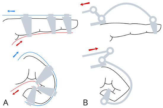
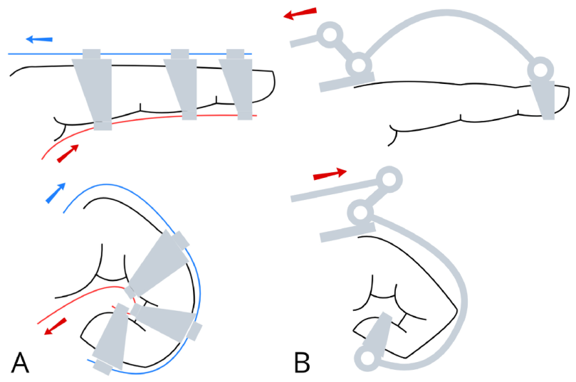
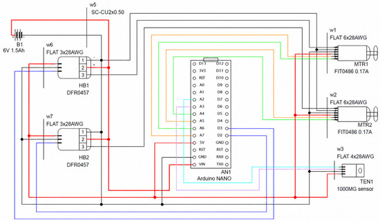
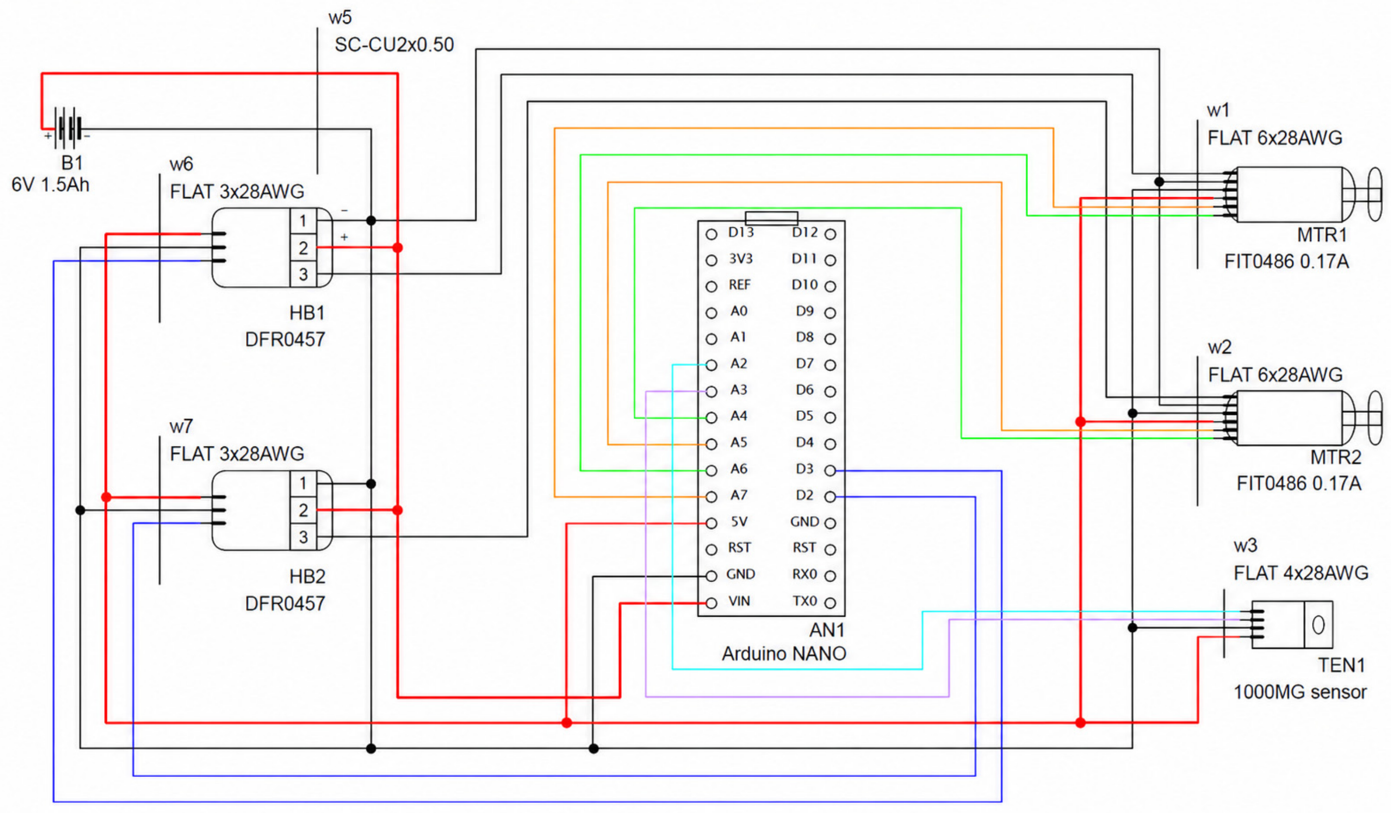
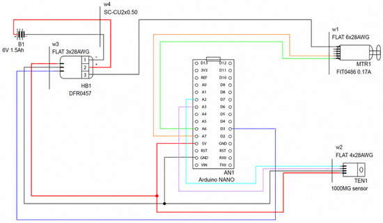
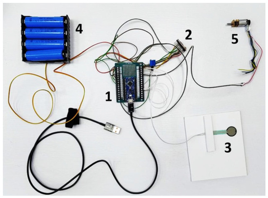
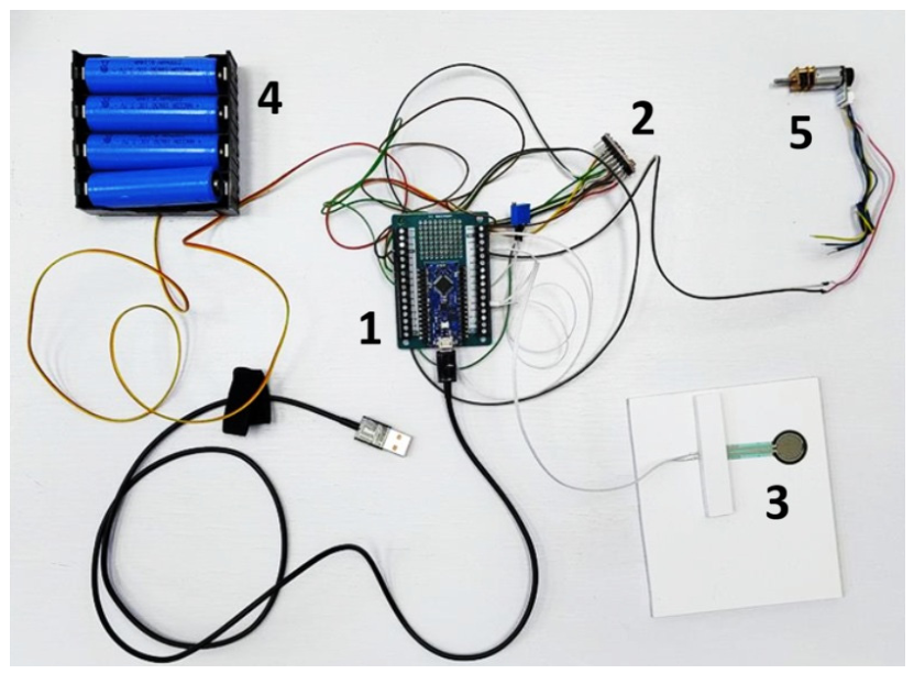
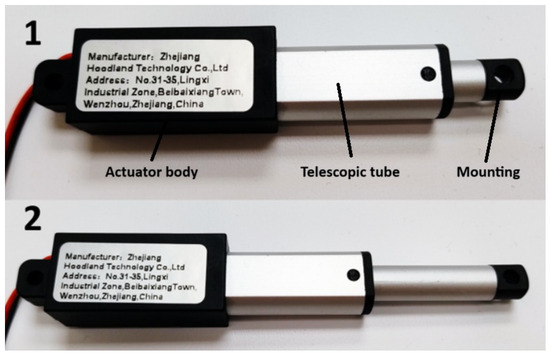
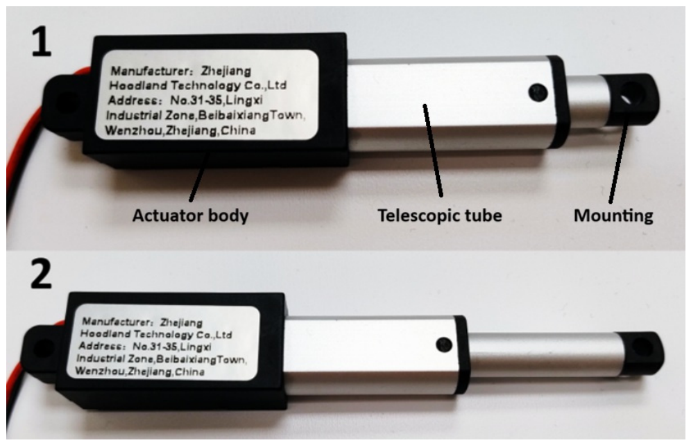
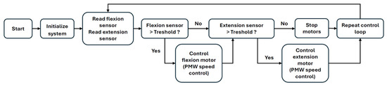
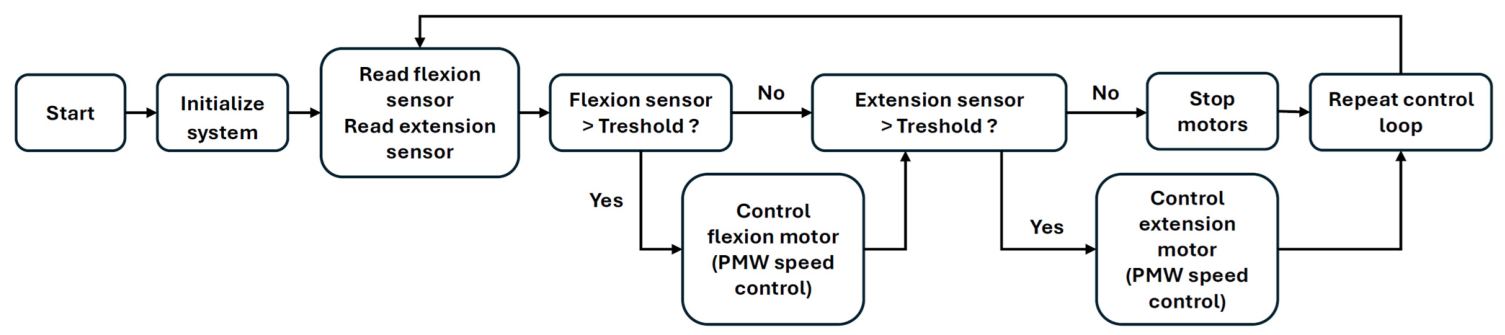
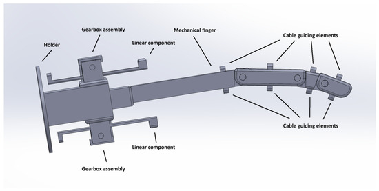
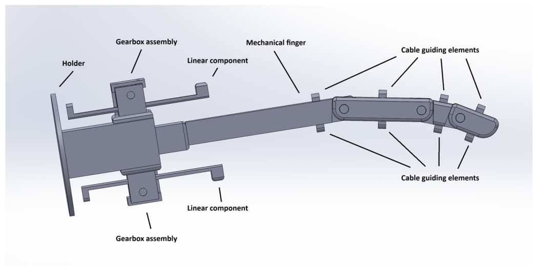
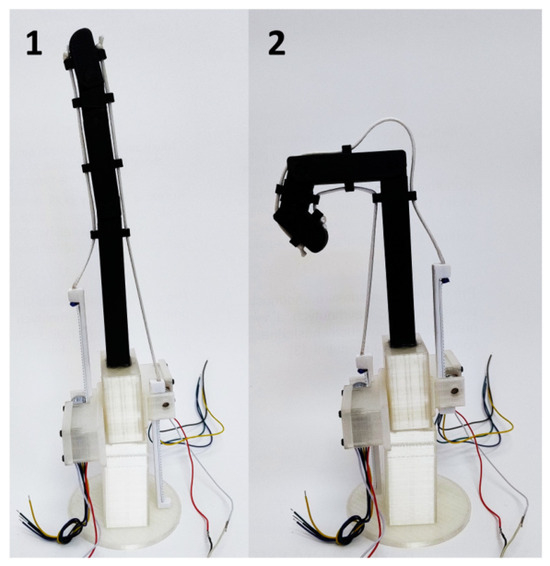
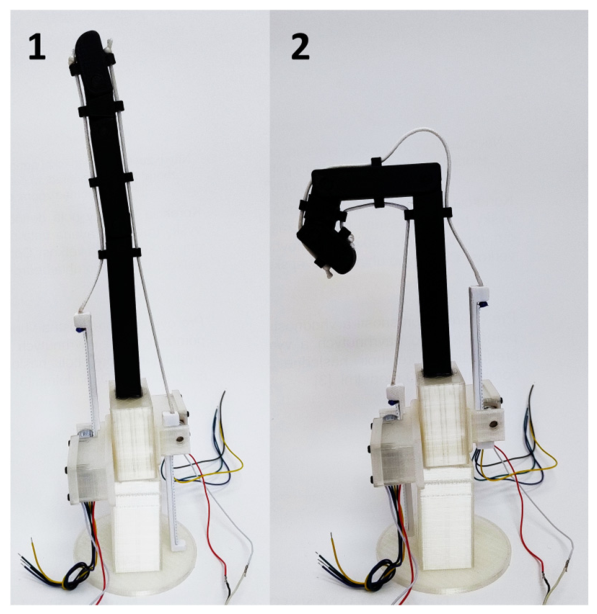
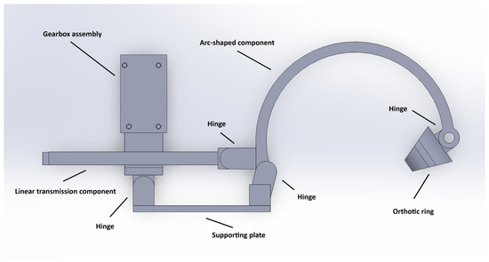
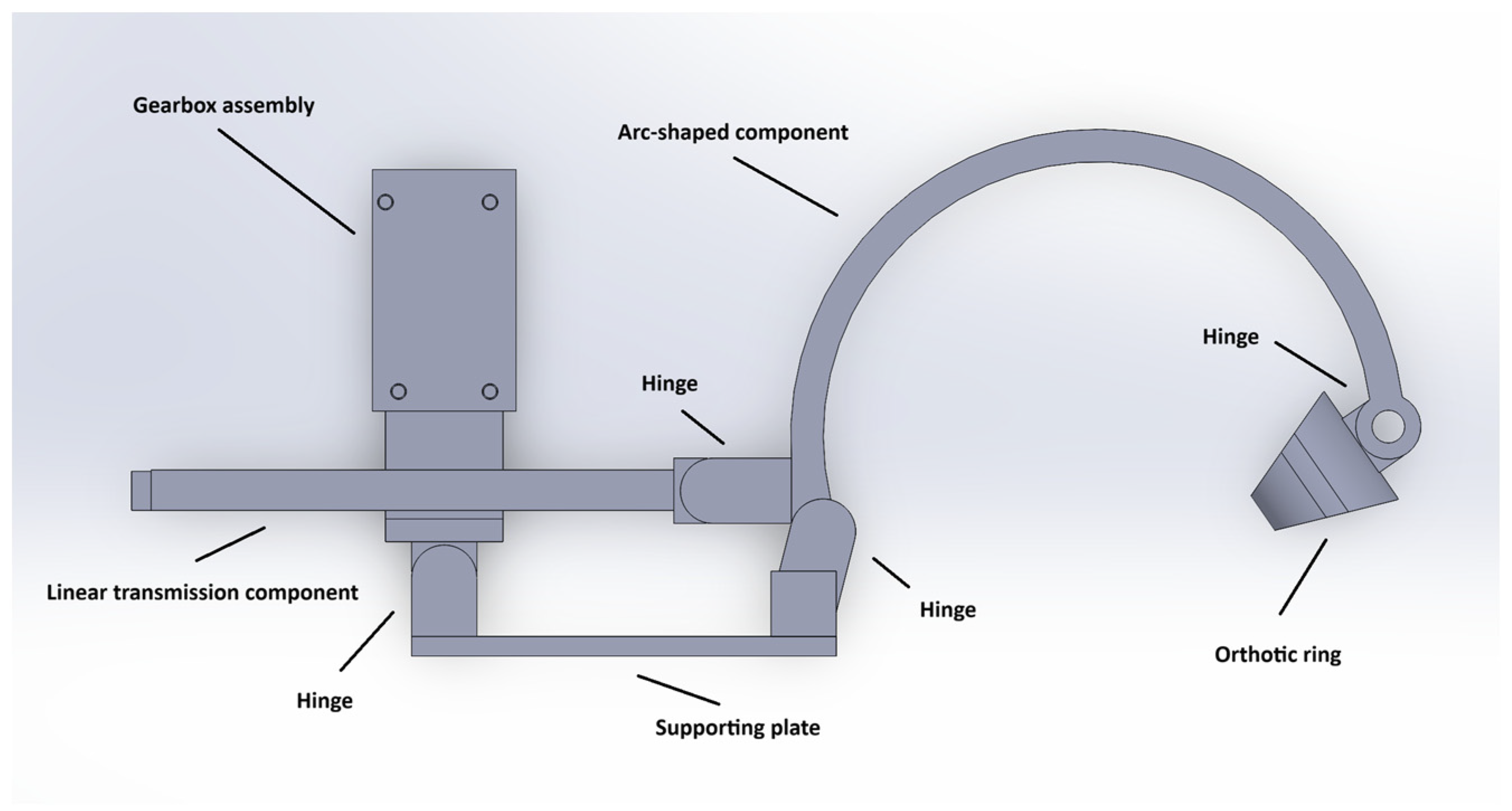
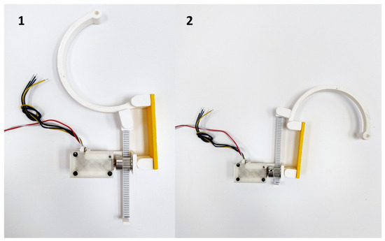
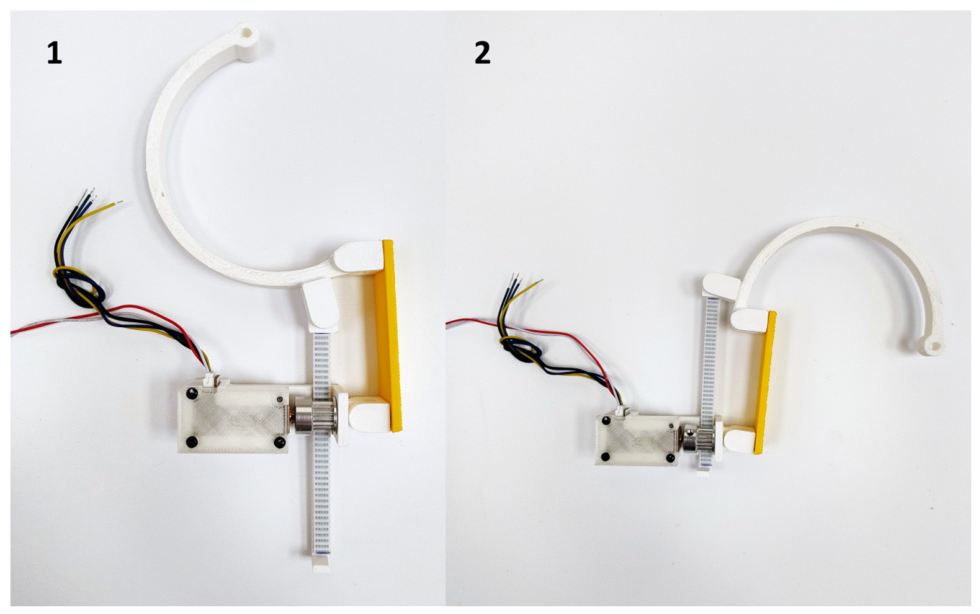
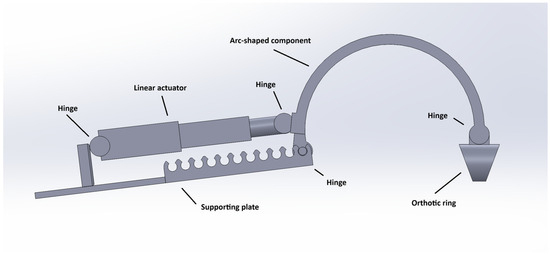
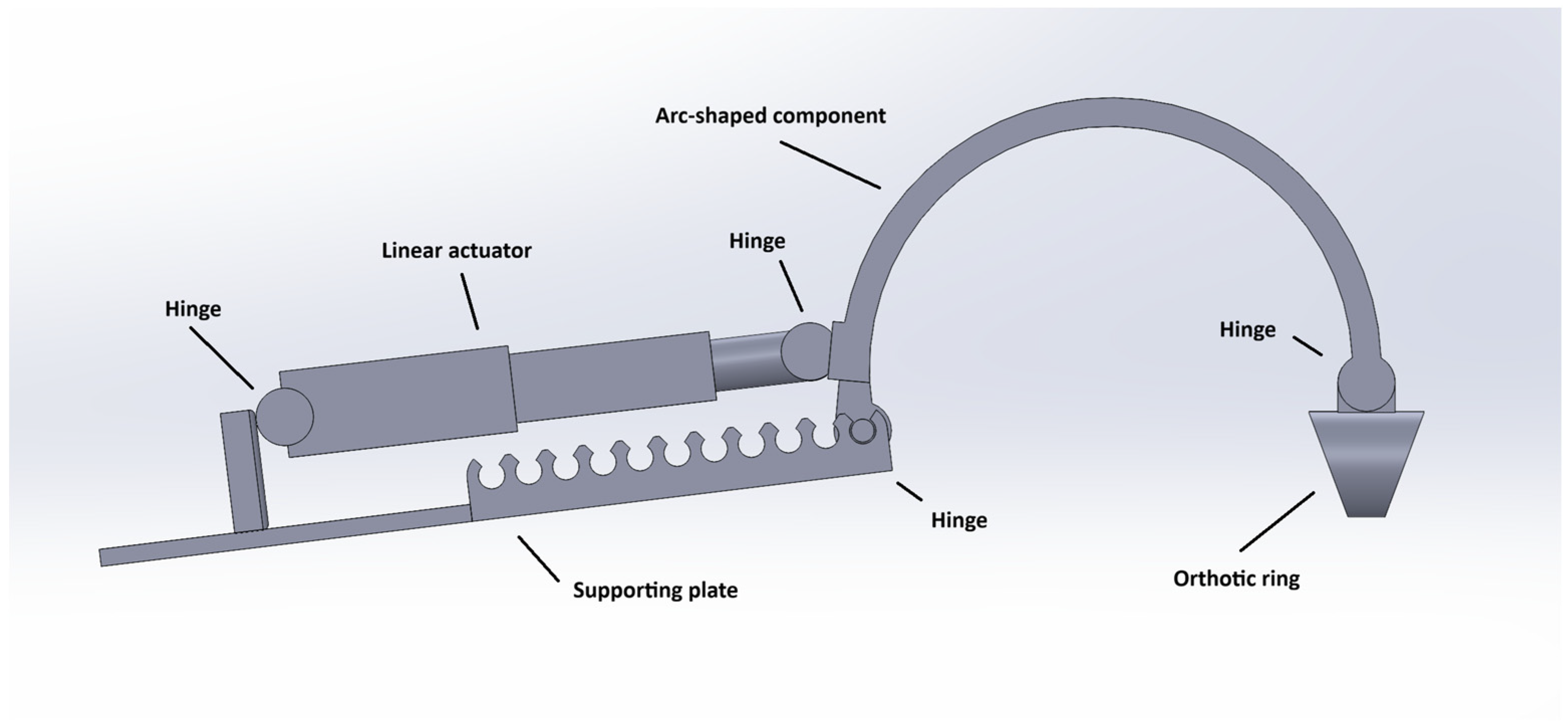
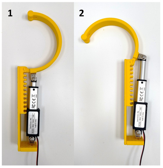
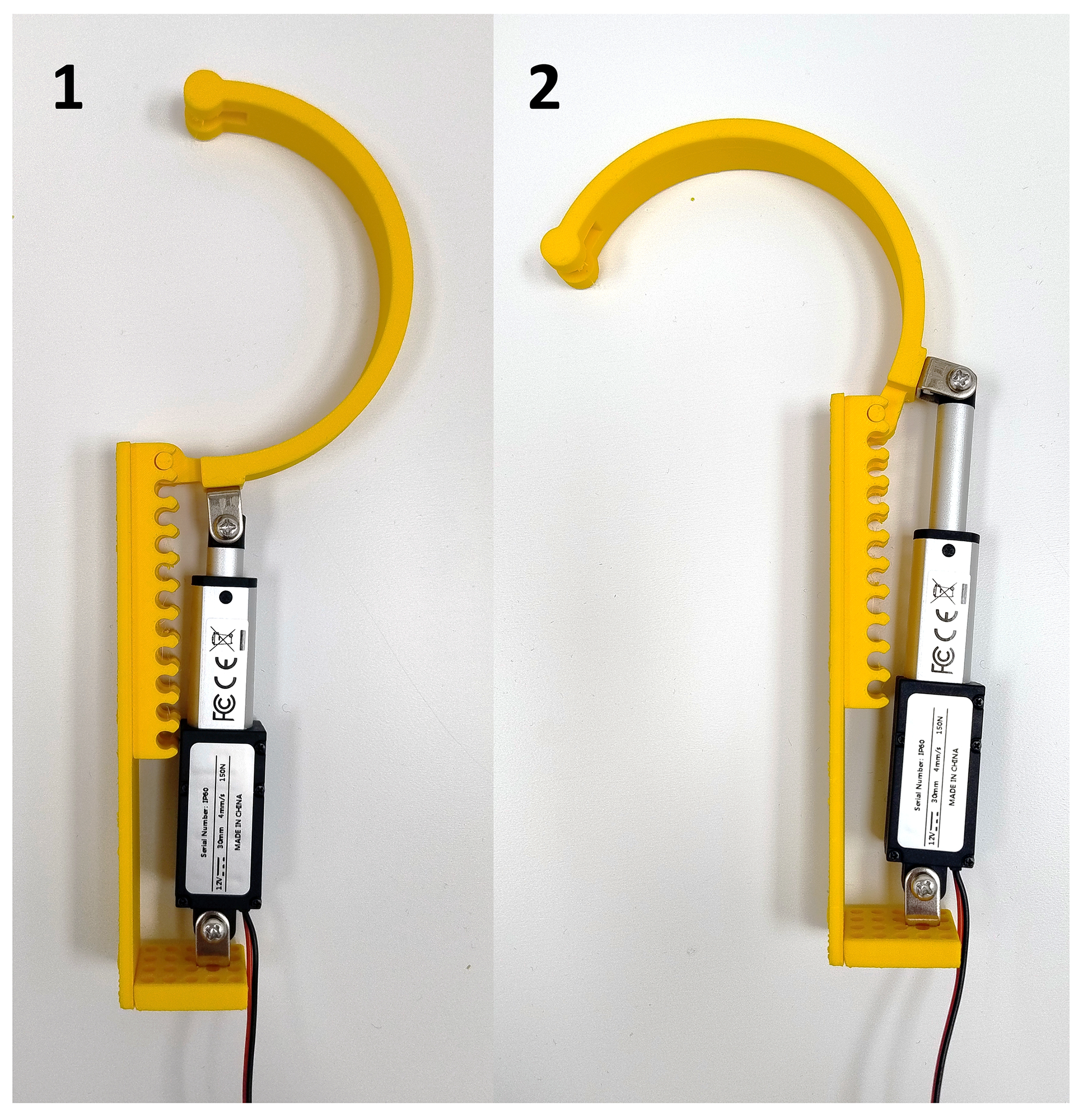
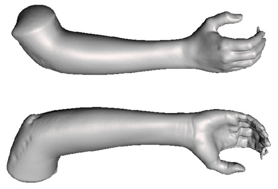
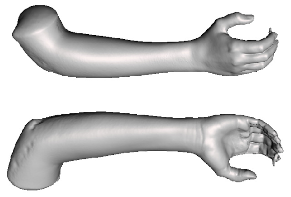
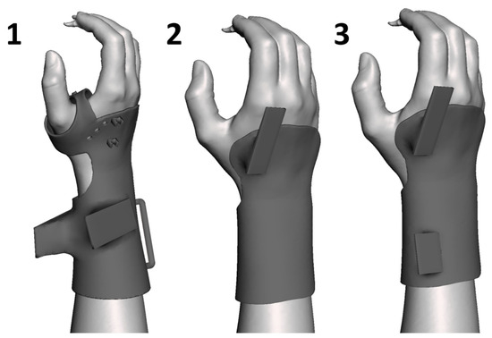
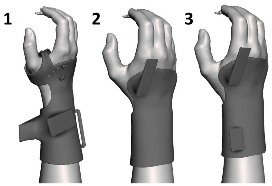
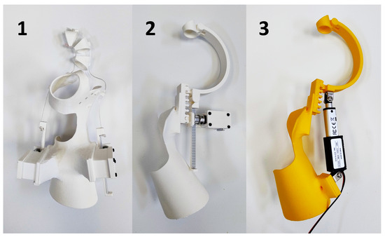
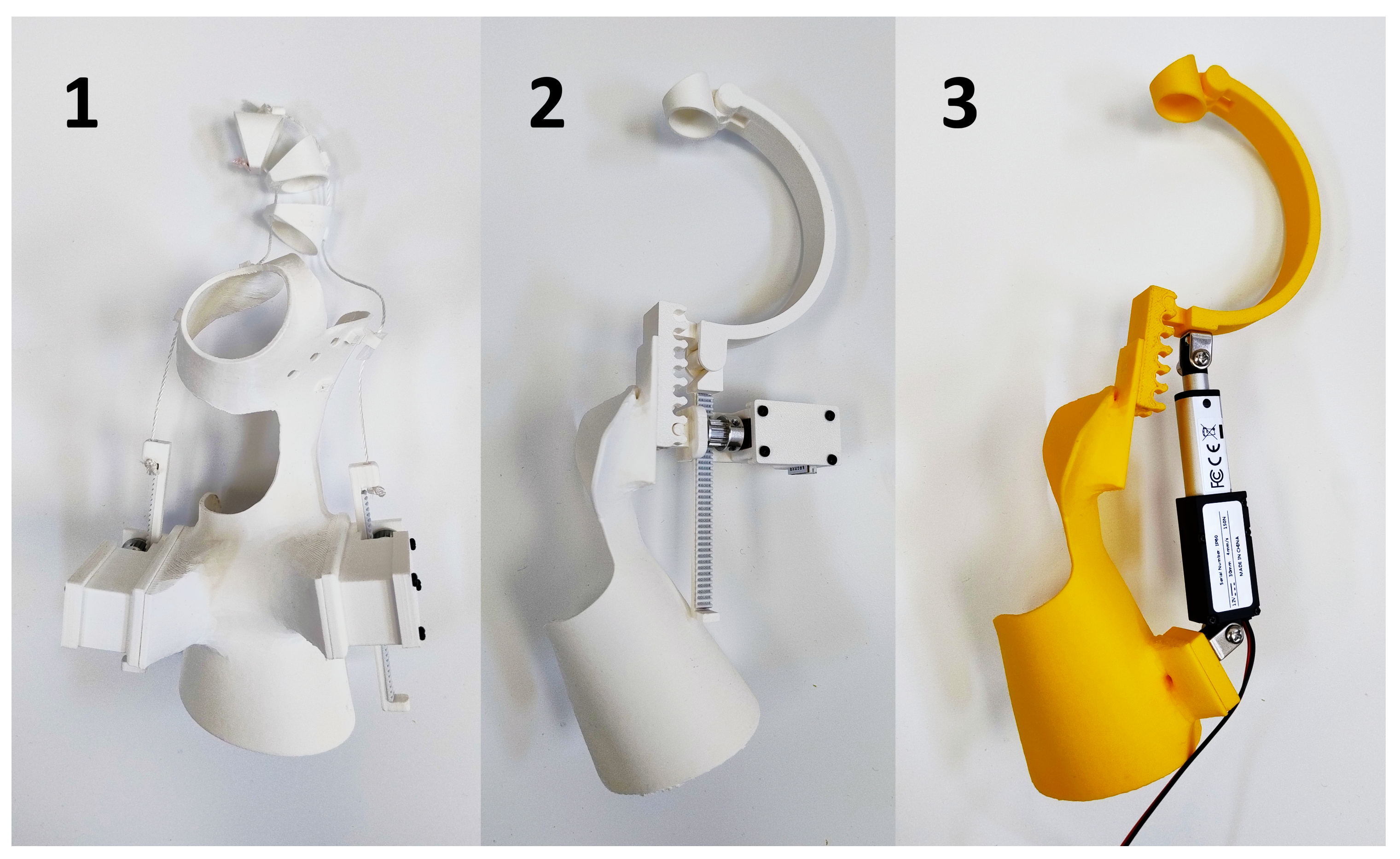
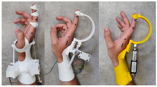
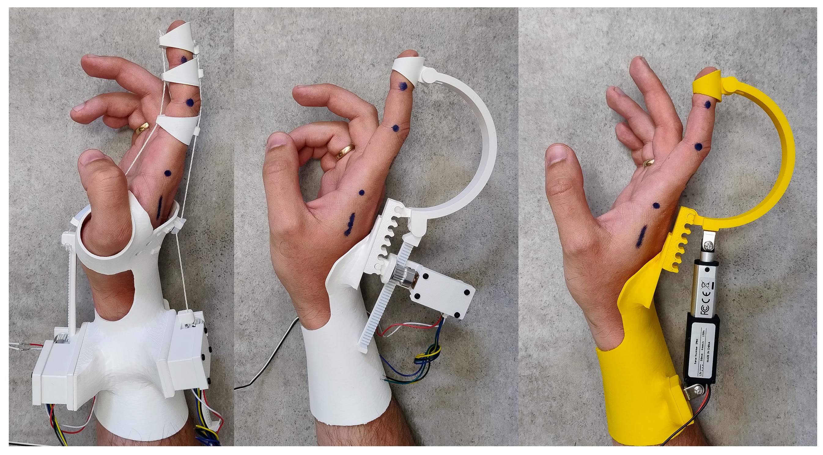
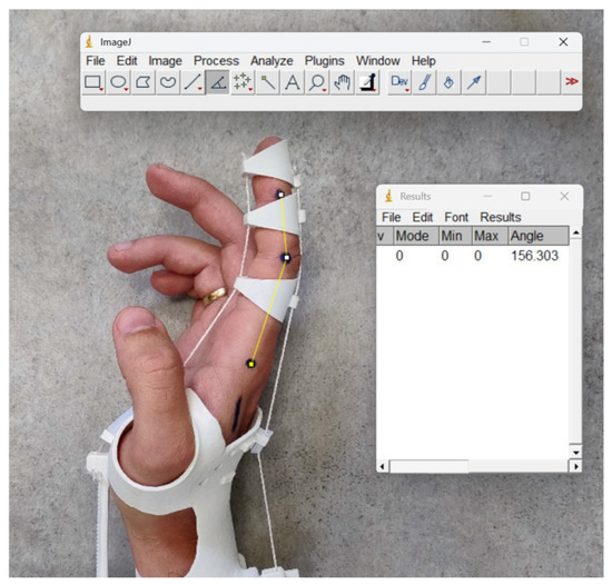
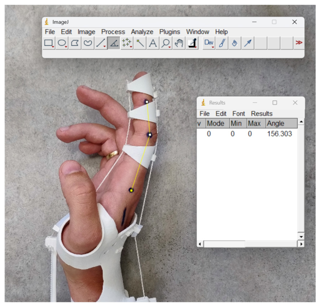
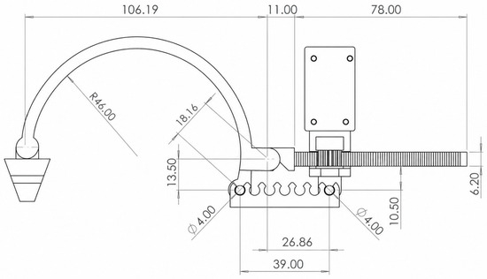
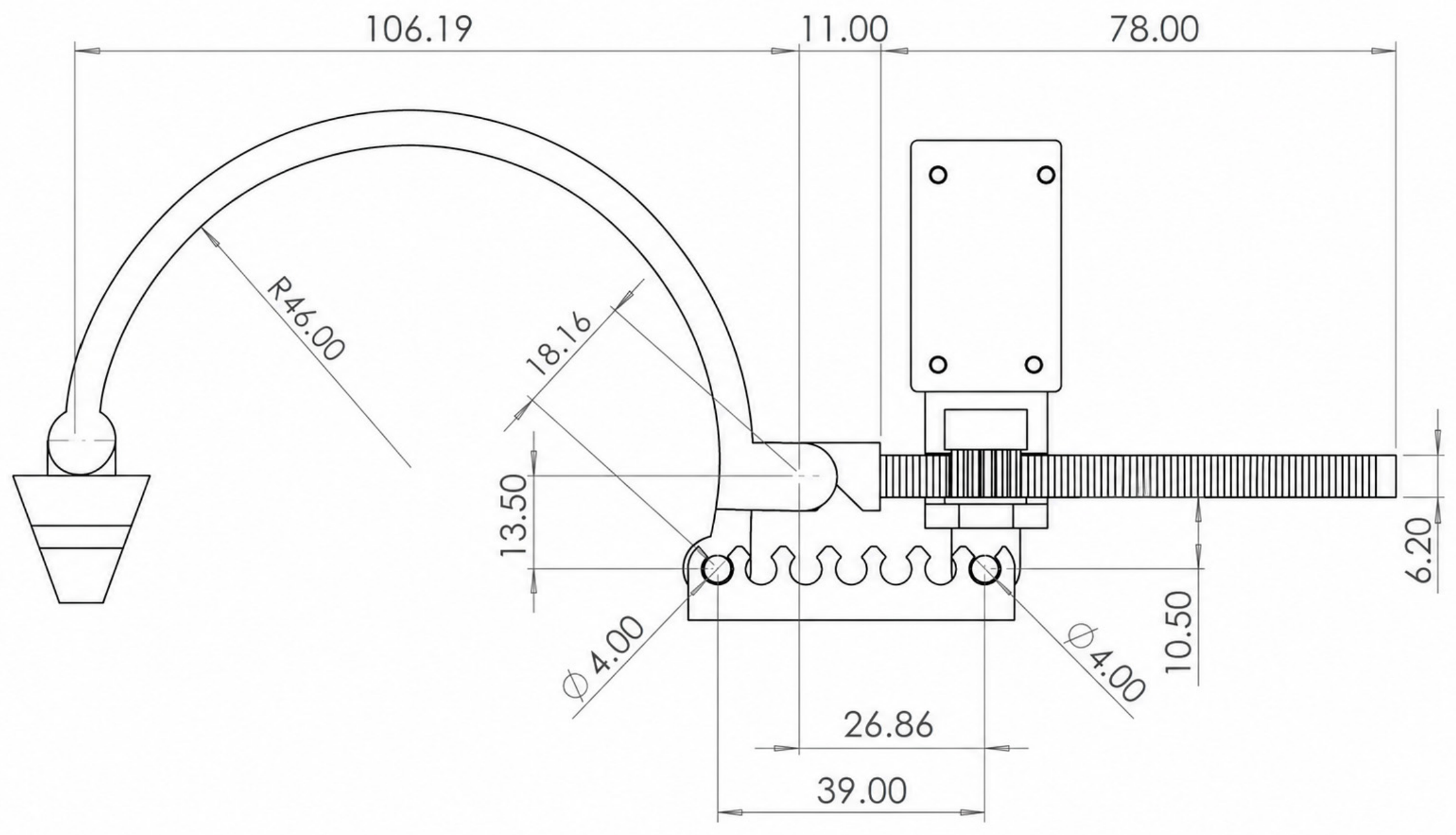
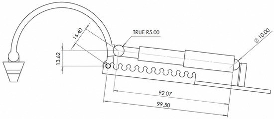
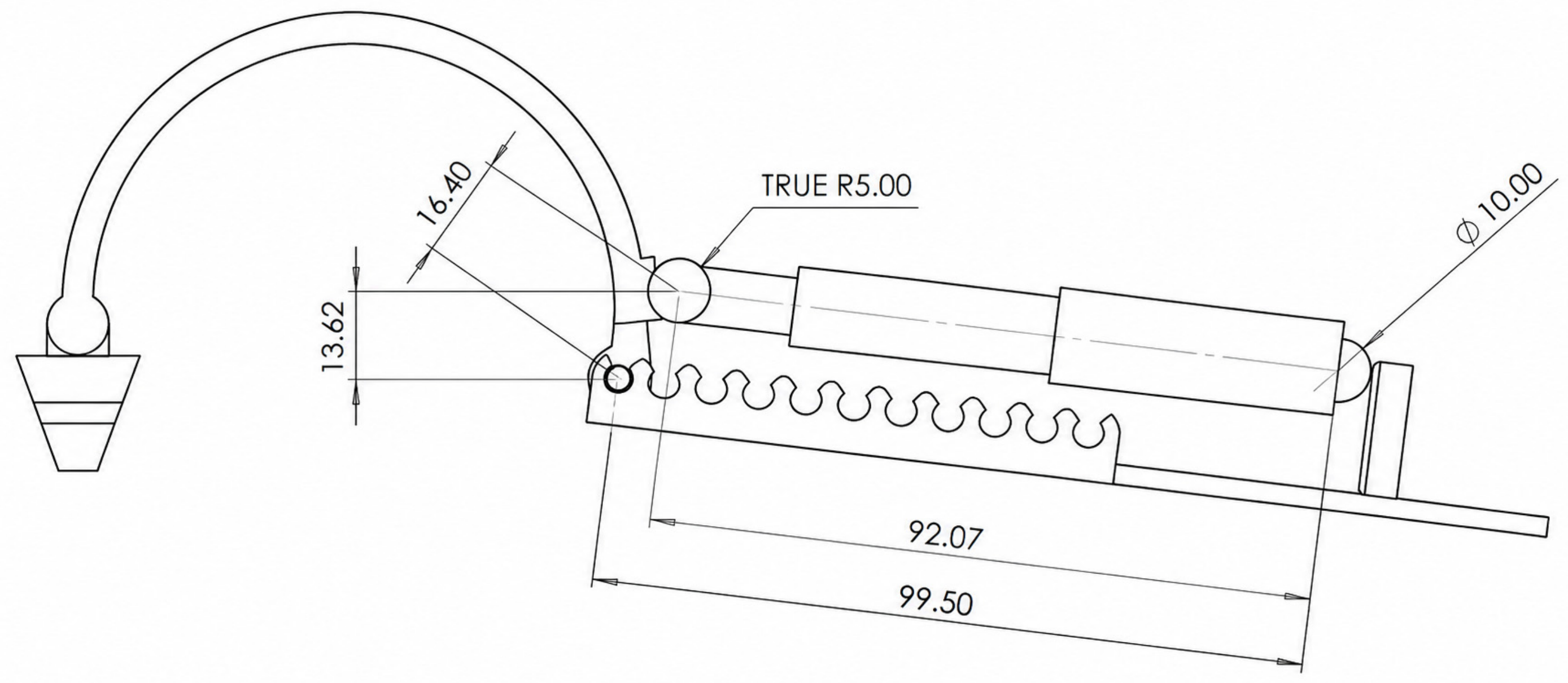

Disclaimer/Publisher’s Note: The statements, opinions and data contained in all publications are solely those of the individual author(s) and contributor(s) and not of MDPI and/or the editor(s). MDPI and/or the editor(s) disclaim responsibility for any injury to people or property resulting from any ideas, methods, instructions or products referred to in the content. |
© 2026 by the authors. Licensee MDPI, Basel, Switzerland. This article is an open access article distributed under the terms and conditions of the Creative Commons Attribution (CC BY) license.