


Abstract
Traditional bone plates provide reliable fracture fixation; however, their high stiffness can cause stress shielding, thereby reducing mechanical stimulation of the bone tissue and slowing its regeneration. The biomechanical performance of a titanium plate with a localized porous structure for osteosynthesis of the radial shaft was investigated in this study. Three designs were considered: a solid plate and two plates with localized porous regions measuring 10 × 10 mm and 10 × 15 mm. The finite element analysis of the bone–plate system was performed using MSC Patran/Nastran, with rigid fixation of the proximal end of the bone and sequential application of an axial compressive load of 100 N, bending, and torsion with a moment of 1 N·m. Biomechanical performance was evaluated based on von Mises equivalent stress, fragment displacement (FD), interfragmentary movement (IFM), interfragmentary strain (IFS), and strain energy density (SED). To confirm the manufacturability of the design, the plate was fabricated from Ti–6Al–4V alloy using laser powder bed fusion (LPBF), and the geometry of the porous structure was verified by scanning electron microscopy. The results showed that the localized porous structure altered the load distribution between the plate and the bone, resulting in an increase in local stresses in the bone under the investigated loading conditions. These changes indicate an alteration in the mechanical environment within the bone, which may potentially affect conditions related to fracture healing. Among the investigated configurations, the plate with a 10 × 10 mm porous insert demonstrated the most balanced mechanical characteristics in terms of stresses in the implant, stress distribution in the bone, and structural stability.
1. Introduction
Diaphyseal fractures are among the most common injuries of the upper extremity and frequently require internal fixation using bone plates for stable osteosynthesis [1,2,3]. Despite the high clinical effectiveness of contemporary plate fixation systems, one of the major challenges remains the mechanical mismatch between metallic implants and native bone tissue. This discrepancy may disrupt the physiological load transfer within the bone and adversely affect the bone remodeling process [4,5,6].
Mechanical loading plays a fundamental role in bone remodeling and regeneration. Numerous studies have demonstrated that various forms of mechanical stimulation, including fluid shear stress, cyclic tensile loading, and vibrational loading, promote the osteogenic differentiation of mesenchymal stem cells, enhance bone matrix synthesis, and stimulate mineralization processes [7,8,9,10,11]. The most pronounced osteogenic response has been observed when cells are cultured within three-dimensional porous scaffolds, which provide a more physiologically relevant mechanical environment than conventional two-dimensional cultures. Consequently, mechanical stimulation is widely recognized as one of the key regulators of new bone formation and an essential factor in accelerating fracture healing.
One of the consequences of Wolff’s law is the stress shielding effect, which occurs when implants with high stiffness are used. Under these conditions, most of the mechanical load is transferred to the fixation plate, while the surrounding bone is subjected to substantially lower loading. Since bone remodeling is regulated by mechanical stimulation, reduced loading leads to a decrease in bone density, the development of localized osteopenia, and delayed bone remodeling. Over time, these changes may result in fixation instability, implant loosening, and an increased risk of refracture following implant removal [12,13].
Consequently, conventional titanium bone plates are prone to inducing stress shielding, thereby reducing the mechanical stimulation of the surrounding bone tissue and potentially impairing bone remodeling and regeneration.
Numerous studies have sought to improve the biomechanical performance of bone plates through optimization of their design and material properties. The primary approaches include geometric and topology optimization aimed at achieving a more efficient material distribution and reducing stress concentrations, as well as tailoring the mechanical properties of implant materials. This issue is particularly significant for titanium fixation plates. The elastic modulus of the widely used biomedical titanium alloy Ti–6Al–4V is approximately 110–120 GPa, whereas the elastic modulus of cortical bone ranges from 15 to 25 GPa. This substantial stiffness mismatch between the implant and bone results in non-uniform load distribution within the bone–plate system, causing a significant proportion of the applied load to be borne by the stiffer implant rather than the bone [14,15,16].
In a previous study [17], an attempt was made to identify the optimal bone plate design for fracture healing and to improve biomechanical performance by systematically evaluating topology-optimized plate geometries under various loading conditions and boundary constraints. The results demonstrated that the PL bone model with a volume fraction (Vf) of 70% exhibited the most favorable biomechanical performance under all loading scenarios, meeting the relevant clinical requirements. Furthermore, fracture callus healing showed the highest stiffness at the earliest stage of healing owing to the favorable biomechanical environment created at the fracture site. However, the optimal topology-optimized plate design was found to depend on fracture geometry, bone type, and fracture location.
In another study [18], three-dimensional locking plates were developed using topology optimization aimed at reducing stress shielding in the surrounding bone tissue. The fixation plates were optimized by minimizing strain energy for three levels of volume reduction (25%, 45%, and 75%). It was demonstrated that reducing the plate volume by up to 75%, while maintaining different screw–hole configurations, increased load transfer to the bone by as much as 37% compared with the original design.
The stiffness of fixation implants can be reduced not only by modifying the plate geometry but also by employing materials with mechanical properties closer to those of cortical bone. Several studies have shown that composite plates based on carbon fiber, flax fiber, epoxy matrices, polyamide, glass fiber, and nano-hydroxyapatite provide a more uniform stress distribution and reduce the stress shielding effect compared with conventional metallic plates [19,20]. Of particular interest are polyetheretherketone (PEEK)-based composites and carbon fiber-reinforced materials, as their lower stiffness enables the preservation of physiological mechanical stimulation of bone tissue throughout the healing process [21,22]. Hybrid metal–composite structures and functionally graded metal–ceramic materials have also been proposed, as they combine adequate fixation strength with reduced implant stiffness [23]. Several investigations have further demonstrated that composite plates can increase load transfer to the fracture site while maintaining fixation stability and reducing bone stiffness loss compared with conventional titanium plates [24,25]. Therefore, the application of composite, hybrid, and functionally graded materials represents a promising strategy for mitigating the stress shielding effect in fracture osteosynthesis.
The rapid development of additive manufacturing has introduced a new approach to addressing this challenge through the use of bone plates incorporating porous or lattice structures. Such designs enable the effective elastic modulus of the implant to be tailored by adjusting the unit cell size, strut thickness, and overall porosity [26,27]. A study by Subasi et al. [28] demonstrated that lattice-filled plates reduced implant stiffness by up to 68% compared with solid plates. At the same time, the average stress within the fracture callus region increased by more than 50%, indicating enhanced mechanical stimulation of bone regeneration.
Similar results have been reported in studies of porous titanium implants fabricated by selective laser melting. It has been demonstrated that the formation of an open interconnected porous structure allows a reduction in the effective stiffness of the implant and creates conditions for bone tissue ingrowth into the pore space, thereby promoting improved osseointegration [29].
The finite element method (FEM) is one of the most widely used computational tools for investigating the stress–strain behavior of bone–implant systems and has been extensively applied to the design and optimization of osteosynthesis devices. In most studies [30,31,32,33], FEM has been employed to evaluate the distributions of stresses, strains, and displacements in both the bone and fixation plate; compare different implant materials and geometries; and investigate the influence of plate thickness, width, length, screw–hole configuration, and structural topology on fracture fixation stability [34,35].
Despite the substantial body of research devoted to optimizing the materials, geometry, and stiffness of bone plates, several important issues remain insufficiently explored. Most published studies have focused on comparing implant materials or evaluating the influence of their mechanical properties on stress distribution. In contrast, relatively few investigations have addressed the application of porous metallic plates for the osteosynthesis of radial shaft fractures while simultaneously considering the biomechanical behavior of the bone–plate system, the stress shielding effect, and the mechanical stimulation required for bone regeneration. Furthermore, finite element analyses in most previous studies have been limited to stress and displacement evaluations, whereas the influence of porous structural parameters on the stress–strain behavior of the bone–implant system and the resulting biomechanical conditions for bone regeneration has received comparatively little attention.
Accordingly, the aim of the present study was to perform a finite element-based biomechanical assessment of the influence of a porous titanium bone plate on the stress–strain behavior of the bone–implant system during osteosynthesis of the radial shaft.
2. Materials and Methods
2.1. Study Object
The dynamic compression plate (DCP) (Figure 1) and modified plates with localized porous inserts developed based on this design were investigated in this study. Bone plates are the most commonly used implants (Figure 1) for internal fracture fixation [36], offering several advantages, including sufficient mechanical stability and high resistance to tensile, compressive, shear, torsional, and bending loads when used in combination with fixation screws [37]. Modern bone plates are typically designed with periarticular geometries and locking screw holes, allowing surgeons to select either locking or non-locking screws depending on the anatomical location and fracture characteristics.
Figure 1.
Dynamic Compression Plate (DCP) for the Radius and Ulna: (a) 3D model; (b) bone–plate assembly.
In the present study, a newly designed porous bone plate was investigated. Its design incorporates a localized porous architecture. This approach aims to improve load transfer between the implant and bone, thereby creating more favorable mechanical conditions for bone remodeling and fracture healing [38]. The plate was fabricated from medical-grade Ti-6Al-4V ELI titanium alloy (ASTM F136), which is widely used in traumatology and orthopedics due to its high strength, corrosion resistance, biocompatibility, and favorable combination of mechanical properties.
The standard 3.5 mm dynamic compression plate (DCP) was used as the control design. It is a straight plate with oval holes for 3.5 mm cortical screws.
2.2. Theoretical Background
Bone tissue regeneration is determined not only by biological factors but also by the mechanical conditions of the surrounding environment. Following fracture fixation, the distribution of mechanical loads within the bone–implant system directly affects callus formation, bone remodeling, and the long-term stability of osteosynthesis. In the present study, the mechanical conditions governing fracture healing were evaluated using four complementary theoretical frameworks: interfragmentary strain theory, strain energy density (SED) theory, a density-dependent model of bone mechanical properties, and a bone remodeling model. The bone remodeling model was subsequently used to determine the reference values of the mechanical stimulus, against which the calculated indicators of mechanical stimulation of bone tissue were interpreted.
2.2.1. Interfragmentary Strain (IFS)
The concept of interfragmentary strain (IFS) was introduced by Perren and is regarded as one of the fundamental criteria for assessing the mechanical stability of bone fractures. According to this theory, successful tissue formation within the fracture gap is governed by the magnitude of the relative deformation occurring between the bone fragments. The classical expression for interfragmentary strain (IFS), proposed by Stephan M. Perren, is given as follows [39,40]:
where:
IFS (Interfragmentary Strain)—interfragmentary strain (% or dimensionless);
ΔL—relative displacement (change in the width) of the fracture gap under loading (mm);
L0—initial fracture gap width (mm).
At low levels of interfragmentary strain, conditions are favorable for new bone formation and primary bone healing. As the strain increases, fibrous or cartilaginous tissue forms initially; however, excessive strain suppresses osteogenesis and impairs fracture healing. Therefore, IFS is considered one of the principal mechanical criteria for evaluating the stability of osteosynthesis.
2.2.2. Strain Energy Density (SED)
Strain energy density (SED) is one of the most informative mechanical parameters, representing the amount of elastic energy stored per unit volume of a material under mechanical loading.
For a linear elastic material, in the three-dimensional formulation [41]:
where:
, , are the normal stresses;
, , are the shear stresses;
—Poisson’s ratio;
—elastic modulus.
For the uniaxial state:
The strain energy density (SED) parameter is widely used in bone remodeling simulations because it reflects the level of mechanical stimulus perceived by bone cells. Insufficient SED values may lead to stress shielding, whereas excessively high SED values can result in localized overloading of the bone tissue.
2.2.3. Dependence of Mechanical Properties on Material Density
To describe the relationship between porosity and the effective mechanical properties of porous titanium, the Gibson–Ashby model is widely used, which allows the evaluation of the influence of the relative material density on its elastic modulus and strength. In general form, the relationship is expressed as follows [42]:
where
E is the elastic modulus of the porous material (GPa);
E0 is the elastic modulus of the fully dense material;
is the density of the porous material;
is the density of fully dense material;
n is an empirical exponent.
The exponent n ranges from 1.5 to 2.5 and is determined by the architecture of the spatial lattice structure, its relative density, as well as the specific characteristics of the additive manufacturing technology. Variation in the unit cell geometry (Diamond, Gyroid, BCC, etc.) and the porosity level allows for targeted control of the elastic modulus and strength of the material, bringing its mechanical characteristics closer to those of bone tissue.
2.2.4. Bone Remodeling Model
Bone remodeling is a continuous process in which bone density changes in response to mechanical loading. In many mathematical models, the remodeling rate is related to the strain energy density (SED) [43]. Accordingly, the remodeling rule can be expressed in terms of the net bone remodeling rate as follows:
where:
—bone tissue density (g/cm3 or kg/m3);
—rate of change in bone tissue density over time;
t—time;
—remodeling rate coefficient, dependent on the current bone density;
S—local mechanical stimulus, most commonly represented by the strain energy density (SED);
S(ref)—reference value of the mechanical stimulus;
s—relative width of the lazy zone, a dimensionless parameter.
2.2.5. Reference Ranges of the Mechanical Stimulus for Bone Remodeling
Mechanical stimulus equation:
SED—strain energy density;
—bone tissue density.
The relative width of the reference range for the mechanical stimulus was set to s = 0.35, corresponding to a range of ±35% relative to the reference value Sref. This value has previously been applied in finite element models of adaptive bone remodeling (Weinans et al.). It should be noted that the parameter s is a parameter of the remodeling model used and does not represent a universal physiological constant. In the present study, the specified threshold values were used solely for an approximate comparative interpretation of the level of mechanical stimulus and were not considered direct criteria for predicting bone tissue regeneration.
The following ranges are then defined:
S < 2.60 J/kg—reduced mechanical stimulation;
2.60 ≤ S ≤ 5.40 J/kg—moderate mechanical stimulation;
S > 5.40 J/kg—increased mechanical stimulation.
When the strain energy density (SED) exceeds the physiological threshold, new bone formation is stimulated. Conversely, when the mechanical stimulus is insufficient, the remodeling rate becomes negative, leading to bone resorption and a reduction in bone density [44].
Thus, changes in the distribution of mechanical loading resulting from the selection of implant material, geometry, or porous architecture have a direct influence on the bone remodeling process. Therefore, the combined analysis of interfragmentary strain (IFS) and strain energy density (SED), together with bone remodeling models, enables the assessment not only of the stress–strain state of the bone–implant system but also of the mechanical conditions governing subsequent fracture healing.
2.3. Computer Modeling
2.3.1. Modeling of the Localized Porous Structure Using DIGIMAT
The design of the localized porous plate was preceded by a numerical modeling stage in the Digimat software 2021 package, aimed at evaluating the effect of the geometric parameters of the lattice structure on its effective mechanical properties. As part of the parametric study, structures with different porosity levels—30%, 40%, 50%, and 60%—were considered, while the pore shape and characteristic pore (unit cell) size were also varied. For each configuration, the effective mechanical properties, including the Young’s modulus and stress state of the structure, were determined. Figure 2 presents representative geometric models of porous structures with porosity levels of 30% and 60%.
Figure 2.
Porous structures with (a) 30% porosity and (b) 60% porosity.
The analysis performed made it possible to determine the influence of each of the considered parameters on the mechanical stiffness of the porous material and to select a rational lattice structure configuration for the subsequent design of the localized porous region of the plate.
Finite Element Mesh and Loading Conditions.
2.3.2. Modeling of the Bone–Plate System
For simplification of the calculations, the cross-section of the radial bone diaphysis was approximated as a hollow cylinder with an outer diameter of 15.9 mm and an inner diameter of 6.37 mm. These dimensions correspond to the range of anatomical dimensions of the radial bone diaphysis in an adult human.
The three-dimensional assembly model of the commercial bone plate with the bone was developed in the Autodesk Inventor computer-aided design system and imported into the MSC Patran software 2021 package, where the finite element model preparation was performed (Figure 2). To ensure the correct transfer of mechanical loads and to investigate the stress distribution within the system, 16 contact pairs were defined. For the contact pairs, a tolerance for searching contacting surfaces of 0.001 m was specified. This approach allows the modeling of stable internal fixation, in which mechanical load is transferred through the “bone–screws–plate” system, and enables the assessment of stress and deformation distribution in the structural components.
In all computational models (solid and porous), the same Tet10 finite element type was used; the difference in the total number of elements was determined solely by the different geometric complexities of the models [45,46]. The finite element size was selected as 0.002 m, which provided the required calculation accuracy while maintaining an acceptable computational time. To evaluate the influence of the finite element size on the calculation results, a mesh independence verification was performed. The analysis demonstrated that further reduction in the element size resulted in a change in the maximum equivalent stresses of less than 5%, indicating sufficient convergence of the finite element model. Figure 3 presents the finite element model of the plate–bone assembly.
Figure 3.
Finite element model of the bone plate: (a) three-dimensional model; (b) finite element mesh model.
Following mesh generation, the finite element model consisted of 43,624 elements. To improve computational accuracy in regions of high stress concentration, including the fracture gap, plate holes, and the contact interfaces between the screws, bone, and plate, local mesh refinement was applied. The resulting mesh accurately represented the geometry of the construct and provided a stable numerical solution for evaluating the stress–strain response of the bone–implant system.
To evaluate the biomechanical performance of the bone–implant construct, three representative physiological loading conditions of the radius were considered: axial compression, bending, and torsion [47]. This approach enables a comprehensive assessment of the mechanical response of the fixation system under loading conditions encountered during normal upper-limb function.
For the axial compression analysis, a longitudinal load of 100 N was applied to the distal end of the radius along its longitudinal axis. This loading condition simulates force transmission through the radius during hand support and routine daily activities.
For the bending analysis, a transverse load of 100 N was applied to the distal end of the bone, producing a bending moment within the construct. This loading configuration was used to evaluate the influence of bending on the stress distribution in the fracture region and fixation plate [48,49].
For the torsional analysis, a torque of 1 N·m was applied to the distal end of the radius to simulate the rotational loading associated with forearm pronation and supination. Loads of 100 N under axial compression and 1 N·m under bending and torsion were selected in accordance with the approach of Liu et al. [47]. As standardized comparative loads for the finite element analysis of radial bone fixation constructs, these values are not intended to reproduce peak physiological loads but are used to ensure identical loading conditions and a valid comparison of the mechanical behavior of the investigated plate variants.
In all loading scenarios, the proximal end of the radius was fully constrained in all degrees of freedom, preventing both translational and rotational displacements. The external loads were applied to the distal end of the bone, allowing force transmission through the internal fixation construct. The corresponding loading configurations are illustrated in Figure 4.
Figure 4.
Mechanical loading conditions applied in the finite element analysis of the bone implant system: (a) axial compression; (b) bending; and (c) torsion.
2.4. Materials
In the finite element modeling, cortical bone tissue was considered as a homogeneous linear elastic isotropic material, the mechanical properties of which corresponded to those of healthy bone tissue of a young patient. This assumption is widely used in finite element studies of orthopedic implants and allows different design configurations to be compared consistently under identical modeling conditions. In reality, the mechanical properties of cortical bone are anisotropic and depend on the orientation of its microstructure; therefore, the use of an isotropic model may affect the absolute values of local stresses and strains. However, since the same bone tissue properties were used for all investigated designs, this simplification does not substantially affect the comparative assessment of the mechanical behavior of the plates or the conclusions drawn [50].
This approach allows the evaluation of the stress–strain state of the “bone–plate” system under physiological mechanical properties of bone. The mechanical properties of all materials used in the modeling are presented in Table 1.
Table 1.
Mechanical properties of the materials used in finite element analysis.
The fracture geometry was defined according to the AO/OTA classification. A 22-A3 [51]: diaphyseal fracture of the radius, representing a simple transverse fracture, was selected as the study model. According to the AO/OTA (Arbeitsgemeinschaft für Osteosynthesefragen/Orthopaedic Trauma Association) classification, the fracture line was oriented nearly perpendicular to the longitudinal axis of the bone, with an inclination angle not exceeding 30°. This fracture type is one of the most common forms of simple diaphyseal fractures and provides an appropriate model for the objective evaluation of the mechanical performance of the internal fixation system.
To simulate the fracture, the bone was divided into two fragments separated by a 1-mm interfragmentary gap. This configuration represents the conditions of secondary bone healing and enables the analysis of stress distribution, strain, and interfragmentary displacement within the fracture region. The selected fracture model is widely used in biomechanical studies and provides a reliable basis for comparing the stress–strain behavior of different fixation plate designs [52].
In the present study, a 1 mm gap between the bone fragments was used exclusively as a standardized parameter of the numerical model, ensuring comparable conditions for the comparative assessment of the mechanical behavior of the investigated plate variants.
The presence of this gap should not be interpreted as a proposed clinical technique for the fixation of a simple transverse fracture of the radius.
3. Results
3.1. Results of Porous Structure Modeling
Based on the numerical calculations performed in DIGIMAT, stress–strain relationships and Young’s modulus were obtained for the investigated porous structure configurations. The resulting curves made it possible to evaluate changes in the effective stiffness of the material depending on the porosity level, pore shape, and pore size. The calculated results for the considered configurations are presented in Figure 5.
Figure 5.
DIGIMAT simulation results for pore diameter 200 μm: (a) spherical pores; (b) ellipsoidal pore shapes.
For convenient comparative analysis, the calculated mechanical characteristics of the Ti–6Al–4V material for different porosity levels and pore shapes were summarized and are presented in Table 2.
Table 2.
Effective elastic modulus and stress values (u = 0.01) for different porosity levels and pore geometries.
The results showed a consistent decrease in the effective Young’s modulus with increasing porosity. At a porosity of 60%, the calculated effective modulus was 27.94 GPa for the model with ellipsoidal pores and 27.5 GPa for the model with spherical pores, whereas the Young’s modulus of solid Ti-6Al-4V was substantially higher. The similar values obtained for the two considered idealized pore shapes indicate that, within the investigated range, the primary parameter governing the reduction in effective stiffness was the porosity level, rather than the specific idealized pore shape.
Based on this preliminary analysis, a porosity of 60% was selected as the target design parameter, providing a substantial reduction in the effective stiffness of the porous material. However, the Digimat results were not used to determine the topology, unit cell size, or strut thickness, nor were they assigned as material properties in the subsequent finite element model.
Based on these findings, a diamond lattice structure with a unit cell size of 1.5 mm and 60% relative porosity was selected for the plate design. In particular, the diamond lattice forms an interconnected porous structure that facilitates bone tissue ingrowth, allows the effective stiffness of the structure to provide a favorable combination of strength and permeability, and can be reliably reproduced using selective laser melting [53,54].
This configuration provided a substantial reduction in structural stiffness while maintaining adequate mechanical strength and ensuring manufacturability by additive manufacturing.
Based on the simulation results, a nominal unit cell size of 1.5 mm and a nominal strut thickness of 785 μm were selected for the final design. These parameters enabled the generation of a regular three-dimensional lattice structure within the central region of the plate corresponding to the fracture site. This design strategy was intended to reduce the local stiffness of the implant while preserving its overall load-bearing capacity and geometric conformity to the anatomical surface of the radius. The selected lattice parameters resulted in a relative porosity of 60%. The porous architecture and the corresponding plate designs incorporating the localized porous structure are shown in Figure 6.
Figure 6.
Design of the bone plate with a localized porous structure: (a) diamond lattice unit used to form the localized porous region; (b) bone plate with a 10 × 10 mm localized porous section; (c) bone plate with a 10 × 15 mm localized porous section.
The localized porous structure generated in the nTopology environment was integrated with the solid model of the bone plate to create a unified geometric model while preserving the external contour and all fixation interfaces. The resulting model was subsequently prepared for import into MSC Patran for finite element analysis.
Because nTopology exports lattice geometries in the STL format, which represents the structure as a triangulated polygonal surface, the generated model was imported into Autodesk Fusion, where the polygonal mesh was converted into a solid body. After reconstruction of the solid geometry, the plate was exported in the Parasolid (*.x_t) format, ensuring accurate transfer of the geometric model to the finite element software without loss of the structural features of the porous architecture.
3.2. Development of a Finite Element Model of the “Bone–Plate with Localized Porous Structure” System
The finite element model of the bone–plate system incorporating a localized porous structure was developed using the same methodology as that employed for the model with the solid osteosynthesis plate. The same geometric model of the radius, the AO/OTA 22-A3 fracture configuration, boundary conditions, loading scenarios, material properties, and contact definitions were adopted.
The finite element model consisted of the radius, the osteosynthesis plate with a localized porous structure, and the fixation screws. Contact pairs were assigned between all mating surfaces to ensure appropriate load transfer throughout the fixation construct.
The only difference between the models was the use of a modified plate incorporating a localized porous region with lengths of 10 mm and 15 mm in the fracture zone. This design enabled a direct comparison of the stress–strain behavior of the bone–implant system with that of the conventional solid plate under identical loading and boundary conditions.
For the porous plates, quadratic tetrahedral TET10 elements with a size of 0.002 m were used. Mesh convergence was assessed by successive mesh refinement. With a further reduction in element size, the change in the maximum equivalent stresses did not exceed 5%, which was adopted as the criterion for sufficient mesh convergence. To model the interaction between the components of the construct, 16 Glue-type contact pairs were created, ensuring coupled load transfer between the contacting surfaces of the bone–screws–plate system.
The finite element models of the bone–plate assemblies incorporating localized porous structures are shown in Figure 7.
Figure 7.
Finite element models of the bone plates: (a) finite element mesh of plate with 10 × 10 mm localized porous insert; (b) finite element mesh of plate with 10 × 15 mm localized porous insert.
The geometric model of the bone–plate system was discretized using ten-node quadratic tetrahedral solid finite elements (Tet10). The use of second-order elements provided a more accurate representation of the complex three-dimensional geometry of the model, including the localized porous structure, and improved the accuracy of the stress–strain state calculations. The finite element size was selected considering the geometric complexity of the structure and the need to adequately reproduce the lattice architecture. The resulting finite element mesh consisted of 406,893 elements. The large number of elements was attributable to the complex geometry of the localized porous region and the need for its detailed representation. The mesh convergence analysis demonstrated that the selected discretization parameters provided a stable and sufficiently accurate numerical solution.
3.3. Results of the Stress–Strain Analysis of the Bone–Plate System
A comprehensive assessment of the stress state of the bone–plate system is provided, with the finite element results presented in two complementary forms. The first identifies the regions of maximum von Mises stress concentration, while the second illustrates the contour distribution (stress contours) across the entire construct, highlighting the gradual variation in stresses from maximum to minimum values. This representation facilitates a clear evaluation of both localized stress concentrations and the overall stress distribution within the bone–plate system.
In addition, total displacement contours are presented to characterize the deformation of the construct, together with stress distribution plots along selected paths passing through characteristic regions of the model. These results enable a comparative evaluation of the mechanical behavior of the bone–plate system and the influence of the fixation plate design on load transfer, stress distribution, and interfragmentary mobility within the fracture region.
A qualitative analysis of the stress contour maps indicates a shift toward higher stress levels in the bone when the porous plate design is used. To quantitatively assess this effect, stresses were evaluated within a predefined region of interest in the cortical bone. Figure 8 presents the von Mises stress distributions in the bone–plate system for the solid plate (Figure 8a), the porous plate with a 10 × 10 mm lattice region (Figure 8b), and the porous plate with a 10 × 15 mm lattice region (Figure 8c).
Figure 8.
Stress distribution in the bone–plate system under compression: (a) solid plate; (b) porous plate with a lattice region size of 10 × 10 mm; (c) porous plate with a lattice region size of 10 × 15 mm.
Figure 8 presents the equivalent von Mises stress distribution fields in the “bone–plate” system when using a solid plate (Figure 8a), a porous plate with a lattice cell size of 10 × 10 mm (Figure 8b), and a porous plate with a lattice cell size of 10 × 15 mm (Figure 8c). For the solid plate, a pronounced stress concentration was observed directly above the fracture site. In contrast, the porous plate designs exhibited a less pronounced stress concentration, with elevated stresses redistributed toward the screw holes and the lattice structure. Despite these changes in the localization of stress concentrations, the overall stress distribution pattern remained similar.
Quantitative analysis showed that the maximum von Mises stress in the cortical bone reached 11.4 MPa, 14.1 MPa, and 17.4 MPa for the solid, 10 × 10 mm porous, and 10 × 15 mm porous plates, respectively. The corresponding maximum stresses in the plates were 171 MPa, 211 MPa, and 259 MPa, respectively.
Figure 9 presents the total displacement distribution fields of the “bone–plate” system when using a solid plate (Figure 9a) and porous plates with lattice cell sizes of 10 × 10 mm (Figure 9b) and 10 × 15 mm (Figure 9c).
Figure 9.
Total displacement distribution in the bone–plate system under axial compression: (a) solid plate; (b) porous plate with a 10 × 10 mm lattice region; and (c) porous plate with a 10 × 15 mm lattice region.
For the solid plate, the maximum displacement was primarily localized within the loaded bone fragment, whereas the opposite fragment exhibited minimal deformation. In contrast, the porous plate designs produced a more uniform displacement distribution, with deformation occurring in both bone fragments, indicating a more homogeneous transfer of mechanical load throughout the bone–plate system.
The maximum displacement of the loaded bone fragment decreased from 1.74 × 10⁻⁴ m for the solid plate to 4.7 × 10⁻⁵ m and 2.68 × 10⁻⁵ m for the 10 × 10 mm and 10 × 15 mm porous plates, respectively. Similarly, the displacement of the opposite bone fragment decreased from 3.56 × 10⁻⁵ m to 6.03 × 10⁻⁵ m and 1.04 × 10⁻⁵ m, respectively.
Figure 10 presents the von Mises stress distributions in the bone–plate assembly under bending loading.
Figure 10.
Stress distribution under bending: (a) solid plate; (b) porous plate with a lattice region size of 10 × 10 mm; (c) porous plate with a lattice region size of 10 × 15 mm.
As shown in Figure 10, the maximum von Mises stresses were localized in the fracture region and at the bone–plate interface in all models. For the solid plate, the maximum stress in the cortical bone reached 5.25 MPa, with a pronounced local stress concentration directly beneath the plate at the fracture site. When the 10 × 10 mm porous plate was used, the maximum stress in the bone increased to 16.1 MPa, while the localized stress concentration became less pronounced and was redistributed toward the porous region and the screw holes. Increasing the porous region to 10 × 15 mm resulted in a maximum bone stress of 9.4 MPa. In this case, the stress distribution became more uniform, with elevated stresses primarily localized around the screw holes and within the porous lattice structure. At the same time, the maximum stress in the plate increased from 78 MPa for the solid design to 242 MPa for the 10 × 10 mm porous plate and 137 MPa for the 10 × 15 mm porous plate.
As shown in Figure 11, the maximum total displacements were localized in the region of load application and around the fracture site in all models.
Figure 11.
Displacement distribution in the bone–plate system under bending: (a) solid plate; (b) porous plate with a lattice region size of 10 × 10 mm; (c) porous plate with a lattice region size of 10 × 15 mm.
Under bending loading, the solid plate demonstrated a maximum displacement of 1.85 × 10⁻⁵ m, with the largest deformation primarily localized in the loaded bone fragment. The 10 × 10 mm porous plate exhibited an increased maximum displacement of 2.60 × 10⁻⁵ m; however, the deformation was distributed more uniformly across both sides of the fracture, indicating that both bone fragments participated more effectively in load transfer. Increasing the porous region to 10 × 15 mm reduced the maximum displacement to 1.96 × 10⁻⁵ m, while maintaining a similar displacement pattern. In this configuration, both bone fragments contributed to the overall deformation, with the maximum displacement remaining concentrated in the fracture region.
The results of the stress–strain analysis under torsional loading are presented in Figure 12 and Figure 13.
Figure 12.
Stress distribution under torsion: (a) solid plate; (b) porous plate with a lattice cell size of 10 × 10 mm; (c) porous plate with a lattice region size of 10 × 15 mm.
Figure 13.
Displacement distribution under torsion: (a) solid plate; (b) porous plate with a lattice region size of 10 × 10 mm; (c) porous plate with a lattice region size of 10 × 15 mm.
For the solid plate, the maximum stress reached 428 MPa and was primarily localized in the central region of the plate near the fracture site. When the porous plates were used, the stress distribution pattern changed: the region of maximum stress shifted toward the loaded side of the plate, with stress concentrations occurring around the adjacent fixation screw holes. The maximum stress in the plate decreased to 337 MPa for the 10 × 10 mm porous design and to 237 MPa for the 10 × 15 mm porous design. At the same time, the stress level in the bone tissue decreased from 28.5 MPa for the solid plate to 22.5 MPa and 15.8 MPa for the porous plate configurations, respectively.
The total displacement distributions of the bone–plate system under torsional loading are presented in Figure 13.
The use of porous plates resulted in a reduction in the maximum displacements of both bone fragments. The most pronounced decrease was observed for the opposite fragment, where the displacement was reduced from 1.35 × 10⁻⁵ m to approximately 3.1 × 10⁻⁶ m. At the same time, the maximum displacement of the loaded fragment decreased from 1.49 × 10⁻⁴ m to approximately 4.6 × 10⁻⁵ m.
4. Discussion
4.1. Mechanical Behavior and Load Transfer of the Bone–Plate System
To comprehensively evaluate the influence of fixation plate design on the mechanical behavior of the bone–plate system, the results of the finite element analysis were systematically summarized. Based on the stress and displacement distribution maps, together with comparative histograms, variations in the stress distribution within both the bone tissue and the fixation plate, interfragmentary displacement, and load transfer characteristics were analyzed for the solid and porous plate designs (Figure 14, Figure 15 and Figure 16). This approach enabled evaluation of the influence of the porous insert geometry not only on the magnitude of the mechanical parameters but also on the load transfer mechanism across the fracture site, which is of critical importance for ensuring fixation stability and providing favorable mechanical conditions for reparative bone regeneration. The stress distribution maps revealed a shift in the stress levels within the bone tissue toward higher values for the porous plate configurations, indicating a more physiologically favorable load-sharing behavior compared with the solid plate design.
Figure 14.
Stress and displacement distributions in the bone–plate system under compression: (a) von Mises stress distribution (pink—bone, grey—plate); (b) displacement distribution (the pink left fragment, the gray right fragment of the bone.).
Figure 15.
Stress and displacement distributions in the bone–plate system under bending: (a) von Mises stress distribution (pink—bone, grey—plate); (b) displacement distribution (the pink—left fragment, the gray—right fragment of the bone).
Figure 16.
Stress and displacement distributions in the bone–plate system under torsion: (a) von Mises stress distribution (pink—bone, grey—plate); (b) displacement distribution (the pink—left fragment, the gray—right fragment of the bone).
The simulation results demonstrate that, under compressive loading, the plate architecture has a significant influence on load redistribution between the implant and the surrounding bone tissue. For the solid plate, the maximum stress within the implant reached 171 MPa, whereas the porous configurations exhibited higher stress levels of 211 MPa and 259 MPa for the 10 × 10 mm and 10 × 15 mm lattice designs, respectively. Compared with the solid configuration, the maximum stress in the plate increased by approximately 23% and 51%, respectively. The higher stress levels observed in the porous plates indicate that the lattice architecture becomes more compliant and accommodates a greater portion of the applied load through deformation of its load-bearing struts. Unlike the solid plate, where the load is distributed over nearly the entire cross-section, the porous architecture concentrates the load within the individual lattice members, resulting in higher local stresses within the implant material.
A corresponding increase in stress was also observed in the bone tissue. The maximum bone stress increased from 11.7 MPa for the solid plate to 14.1 MPa and 17.3 MPa for the 10 × 10 mm and 10 × 15 mm porous designs, respectively. These results indicate that the porous plates enhance the transfer of physiological load directly to the bone. Such physiological load transfer is considered beneficial for mechanical stimulation of bone remodeling and callus formation during fracture healing.
The displacement analysis also revealed substantial changes in the mechanical response of the fixation system. For the solid plate, the maximum displacement of the left bone fragment reached 1.74 × 10⁻⁴ m, whereas it decreased to 4.7 × 10⁻⁵ m and 2.68 × 10⁻⁵ m for the 10 × 10 mm and 10 × 15 mm porous plates, respectively. This reduction indicates a considerable decrease in excessive mobility of the loaded bone fragment. In contrast, the displacement of the right fragment increased from 3.56 × 10⁻⁵ m for the solid plate to 6.03 × 10⁻⁵ m for the 10 × 10 mm configuration, followed by a decrease to 1.40 × 10⁻⁵ m for the 10 × 15 mm design. This redistribution of displacements indicates more coordinated deformation of the bone fragments and a change in the load-transfer behavior across the fracture site, resulting in a reduction in the relative interfragmentary movement (IFM).
From a biomechanical perspective, the 10 × 10 mm porous configuration exhibited the most favorable mechanical performance. Although the lattice architecture increased the stress within the plate, it simultaneously enhanced mechanical stimulation of the bone while promoting a more balanced distribution of displacement between the fracture fragments. This behavior indicates reduced deformation localization within the loaded fragment and more efficient load transfer throughout the bone–plate construct. In contrast, the 10 × 15 mm lattice configuration resulted in further increases in stress within both the implant and the bone; however, this was accompanied by a reduction in the displacement of the right fragment, suggesting increased local stiffness of the lattice members and a less uniform deformation pattern compared with the 10 × 10 mm design.
Among the investigated designs, the plate incorporating the 10 × 10 mm lattice architecture demonstrated the most balanced stress–strain response, whereas further enlargement of the lattice cell size increased stress levels without providing additional improvement in the kinematic behavior of the fracture fragments.
Under bending loading, the porous plates exhibited greater displacement than the solid configuration (Figure 15). This behavior is attributed to the reduced effective bending stiffness resulting from the decrease in the load-bearing cross-sectional area and the lower equivalent elastic modulus of the lattice architecture.
Under a constant external load, the reduction in the effective bending stiffness of the porous plate results in a greater overall deflection of the bone–plate construct. However, increasing the length of the porous region reduced the maximum displacement by approximately 25%. For diamond or similar lattice architectures, increasing the porous region length effectively increases the number of repeating unit cells. Consequently, a greater number of inclined struts participate in load bearing, the applied load is redistributed among more structural elements, and the load carried by each individual unit cell decreases. As a result, local deformation is reduced.
The simulation results further demonstrate that modifications to the plate geometry substantially influence the distribution of mechanical loads between the implant and the surrounding bone tissue. For the solid plate, the maximum stress reached 5.25 MPa in the bone and 78 MPa in the implant. After introducing the porous architecture with a 10 × 10 mm lattice region, the maximum stresses increased to 16.1 MPa in the bone and 242 MPa in the plate. When the porous region was extended to 10 × 15 mm, the maximum stress decreased to 9.14 MPa in the bone and 137 MPa in the implant.
From a biomechanical perspective, the solid plate possesses high structural stiffness, causing a substantial proportion of the external load to be carried by the implant itself. This behavior results in stress shielding of the bone and consequently reduces the mechanical stimulation within the fracture region. Although the stress within the implant remains relatively low, the surrounding bone experiences only limited physiological loading, which may delay bone remodeling and callus formation.
The porous plate with a 10 × 10 mm lattice region produced a pronounced redistribution of the applied load. At the same time, the higher stresses observed in the implant are associated with stress concentration within the lattice struts, which primarily resist tensile and compressive loading.
When the porous region was increased to 10 × 15 mm, stress levels in both the implant and the bone decreased relative to the 10 × 10 mm configuration. This finding suggests a reduction in the efficiency of load transfer through the bone–plate construct. A likely explanation is that enlarging the lattice cells decreases the number of load-bearing struts, thereby reducing the local stiffness of the porous architecture and altering the load-transfer pathway.
The displacement analysis further confirmed the differences in the mechanical response of the investigated designs. For the solid plate, the displacements of the left and right bone fragments were 1.50 × 10⁻⁵ m and 1.85 × 10⁻⁵ m, respectively. With the 10 × 10 mm porous plate, the displacement of the loaded (left) fragment slightly increased to 1.70 × 10⁻⁵ m, whereas the displacement of the opposite fragment decreased to 1.56 × 10⁻⁵ m. This redistribution indicates more uniform load transfer across the fracture site and reduced asymmetry in the deformation of the bone–plate system.
The 10 × 15 mm porous configuration also reduced stress shielding compared with the solid plate; however, it was less effective than the 10 × 10 mm design in terms of mechanical stimulation of the bone and physiological load transfer. Therefore, among the investigated configurations, the plate incorporating the 10 × 10 mm porous architecture provides the most favorable balance between implant flexibility, load sharing, and mechanical stimulation of the surrounding bone tissue, making it the most promising design for promoting bone regeneration. This is why the structure with a lattice cell size of 10 × 10 mm can be considered the most rational among the investigated variants in terms of providing favorable conditions for bone tissue regeneration.
The comparative diagrams presented in Figure 16 illustrate the influence of plate architecture on the stress–strain behavior of the bone–plate system under torsional loading. The simulation results demonstrate that the introduction of a porous architecture substantially affects both stress redistribution and the mechanical response of the bone–plate construct under torsion.
Under torsional loading, the maximum stress in the fixation plate decreased progressively from 428 MPa for the solid configuration to 337 MPa and 237 MPa for the plates incorporating 10 × 10 mm and 10 × 15 mm porous regions, respectively. A corresponding reduction in the maximum stress within the bone tissue was also observed, decreasing from 28.5 MPa to 22.5 MPa and 15.8 MPa, respectively. These findings indicate that increasing the degree of porosity reduces the overall torsional stiffness of the fixation plate and promotes a more uniform distribution of the applied torque throughout the lattice architecture, thereby reducing local stress concentrations in both the implant and the adjacent bone tissue.
The displacement analysis revealed that the solid plate exhibited pronounced asymmetry in the motion of the fracture fragments. The displacement of the left fragment reached 1.49 × 10⁻⁴ m, whereas the right fragment displaced only 1.36 × 10⁻⁵ m, indicating highly non-uniform transmission of the torsional load. The introduction of a porous architecture reduced the maximum displacement of the left fragment to 4.59 × 10⁻⁵ m for the 10 × 10 mm configuration and 4.89 × 10⁻⁵ m for the 10 × 15 mm configuration. At the same time, the displacement of the right fragment decreased to 3.06 × 10⁻⁵ m and 3.12 × 10⁻⁵ m, respectively. Consequently, the difference in fragment mobility became substantially smaller, demonstrating a more uniform distribution of deformation across the fracture site.
From a biomechanical perspective, the incorporation of a locally porous architecture under torsional loading reduces stress concentrations while promoting a more balanced transfer of torque between the fixation plate and the surrounding bone. Among the investigated designs, the plate with the 10 × 10 mm porous region exhibited the most favorable combination of mechanical strength and deformation uniformity. Although increasing the porous region to 10 × 15 mm further reduced the stress levels, it did not provide a noticeable improvement in the kinematic behavior of the fracture fragments, suggesting that the reduction in overall structural stiffness was not accompanied by a corresponding enhancement in deformation distribution.
Under torsional loading, the lattice members resist not only bending but also axial tension and compression along their inclined struts. This three-dimensional truss-like architecture effectively limits rotational displacement of the fracture fragments. Consequently, a portion of the applied torque is carried by the interconnected network of inclined lattice members rather than solely by the solid implant material. In the solid plate, torsional loading tends to concentrate in localized regions between adjacent screw holes, whereas in the lattice-based design the torque is distributed among numerous unit cells. This more homogeneous load-sharing mechanism reduces local deformation and enhances the overall mechanical stability of the bone–plate construct.
The obtained stress–strain state results for the bone–plate system is consistent with the general trend established in studies on the optimization of metallic osteosynthesis plates: reducing implant stiffness promotes redistribution of mechanical load from the plate to the bone tissue. For example, Campoli et al. [55] demonstrated through three-dimensional topology optimization of locking compression plates that a controlled reduction in material volume can decrease the stiffness of the structure and, consequently, potentially reduce the stress-shielding effect. The authors considered different levels of material volume reduction (25%, 45%, and 75%) under compression, bending, torsion, and combined loading conditions.
To assess the mechanical reliability of the plates, the factor of safety was calculated as the ratio of the yield strength of Ti–6Al–4V to the maximum equivalent von Mises stress. The factor of safety was determined according to the yield criterion as the ratio of the yield strength of the Ti–6Al–4V alloy to the maximum equivalent von Mises stress:
A yield strength of 945 MPa was adopted. The calculation results for all investigated plate configurations and loading conditions are presented in Table 3.
Table 3.
Strength assessment of the investigated plate configurations under different loading conditions.
These results demonstrate that the maximum equivalent stresses remained below the yield strength of Ti-6Al-4V in all loading scenarios, indicating that the developed fixation plates operate entirely within the elastic regime and possess sufficient mechanical reliability for the investigated loading conditions. For all investigated plate configurations, the factor of safety exceeded 2.0, indicating an acceptable level of static reliability and suggesting that the yield strength would not be reached under the specified loading conditions. However, the final assessment of the structural reliability requires further static and fatigue testing. The trend observed in the present study is consistent with the findings of previous studies, according to which a reduction in the local stiffness of a metallic fixation device promotes a redistribution of load between the implant and the bone tissue. However, unlike approaches involving a global reduction in material volume or modification of the geometry of the entire plate [56], the present study altered mechanical compliance only within the localized region adjacent to the fracture site. The results obtained in this study demonstrate that this approach makes it possible to control load transfer to the bone tissue without requiring substantial modification of the overall plate design, which could lead to the formation of additional stress concentrations. At the same time, an increase in the size of the porous region is accompanied by a higher mechanical load on the implant, highlighting the need to determine an optimal balance between local compliance and structural strength.
4.2. Evaluation of the Mechanobiological Conditions for Bone Regeneration
For the comparative assessment of the mechanical conditions at the fracture site, the resulting interfragmentary displacement (Fragment Displacement, FD) and strain energy density (SED) were used. FD was defined as the magnitude of the resulting displacement (Displacement Magnitude) at the fracture site. The FD parameter was determined based on the resulting displacement magnitude (Displacement Magnitude) and was used exclusively for the comparative assessment of the mechanical stability of the investigated configurations under identical loading conditions. The SED values were obtained directly from the finite element analysis results in MSC Patran using the built-in output parameter Strain Energy, Energy Density. To ensure comparability among the investigated configurations, the analysis was performed within the same region of cortical bone adjacent to the fracture site for the corresponding loading condition.
Interfragmentary Movement (IFM) was determined from the finite element analysis results as the relative displacement between a pair of corresponding nodes located on the opposite surfaces of the bone fragments in the fracture zone. For each selected node, the displacement components were extracted from the calculation results, after which IFM was calculated as the difference in displacements between the corresponding nodes on either side of the interfragmentary gap. This approach allowed the relative movement of the fracture surfaces to be assessed rather than the absolute resultant displacement of an individual bone fragment (Displacement Magnitude). The obtained IFM value was subsequently used to calculate the interfragmentary strain (IFS), taking into account the initial gap of 1 mm.
The combined analysis of the FD, IFS, and SED parameters was used to comparatively assess the influence of plate design on the mechanical stability of the bone–plate system and the mechanical conditions at the fracture site. The reference values are provided in Section 2.2, “Theoretical Background.”
The obtained results are presented in Table 4.
Table 4.
Comparison of Mechanical Parameters (IFM, IFS, and SED) for Different Plate Configurations and Loading Conditions.
It should be noted that the mathematical bone remodeling model presented in Section 2.3.2 was not used to model the temporal evolution of bone tissue density or the fracture healing process. In the present study, it was included solely as a theoretical basis for interpreting the obtained mechanical parameters (FD, IFM, IFS, and SED). Accordingly, the data presented in Table 4 represent the results of the mechanical finite element analysis rather than the modeling of bone regeneration or remodeling processes.
The obtained results are consistent with recent finite element studies of osteosynthesis of the radial shaft, which have demonstrated that maintaining interfragmentary strain within a range corresponding to stable fixation, while preserving physiological load transfer to the bone tissue, contributes to more favorable mechanical conditions at the fracture site. Despite the differences in the assessment criteria used (interfragmentary movement and interfragmentary strain (IFM/IFS) according to the Perren criterion in the present study, and minimum principal strain ε3 in the study by Matsuura et al. [57]), the obtained results are of a comparable order of magnitude and demonstrate the same biomechanical trend. In both studies, a reduction in interfragmentary motion was accompanied by the preservation of mechanical load transfer to the bone tissue, indicating the establishment of more balanced mechanical conditions within the bone–implant system.
A novel aspect of the present study is the establishment of a relationship between the geometric parameters of the localized porous region of the plate and the mechanical conditions at the site of a radial shaft fracture. The results demonstrate that local modification of plate stiffness can be used as a design parameter to achieve a balance between fixation stability and load transfer to the bone tissue.
Among the investigated designs, the plate with a localized 10 × 10 mm porous insert demonstrated the most rational performance. This configuration provided the most balanced combination of mechanical characteristics. Under compression, it demonstrated a low interfragmentary strain (IFS = 0.4%), corresponding to conditions of high fixation stability, while simultaneously increasing load transfer to the bone tissue compared with the solid plate. Under bending, the 10 × 10 mm configuration exhibited the minimum interfragmentary motion (FD = 0.0015 mm), while the IFS value of 3.1% fell within the range considered potentially favorable for bone tissue regeneration according to Perren’s interfragmentary strain theory. Under torsional loading, the 10 × 10 mm porous insert reduced interfragmentary motion compared with the solid plate and exhibited a higher strain energy density (SED), with values of 6.72 for the 10 × 10 mm configuration and 2.78 for the 10 × 15 mm configuration. This indicates more pronounced localized mechanical load transfer and more intensive mechanical stimulation of the bone tissue in the 10 × 10 mm configuration. Thus, the plate with the 10 × 10 mm porous insert demonstrated the most balanced combination of fixation stability, load transfer, and localized distribution of mechanical effects and was therefore selected as the most rational design configuration.
4.3. Additive Manufacturing of the Plates with Localized Porous Structures
The comparative study demonstrated that, among the investigated configurations, the plate with a localized 10 × 10 mm porous insert was the most rational design. This configuration provided the most balanced combination of mechanical strength, fixation stability, and load transfer to the bone tissue. Compared with the solid plate, this configuration provided more efficient mechanical load transfer to the bone tissue, increased mechanical stimulation at the fracture site, and a more favorable distribution of mechanical parameters (IFM, IFS, and SED) without a significant increase in stresses within the plate itself. To assess the reproducibility of the additive manufacturing process and the conformity of the obtained geometry with the developed design, specimens of the bone plate with a localized porous structure were fabricated. The application of laser-powder bed fusion (l-PBF) technology enabled the accurate reproduction of the designed geometry, including both solid and porous regions, while ensuring the formation of a regular lattice structure according to the developed CAD model.
The prototype specimens were manufactured at the University of Wolverhampton (United Kingdom) using metal additive manufacturing equipment (EOS M290) designed for the fabrication of medical-grade Ti–6Al–4V alloy components. The obtained samples were used to evaluate the manufacturability of the proposed design and for subsequent experimental investigations.
Feedstock Material and Powder Bed Fusion Processing.
All specimens were fabricated using gas-atomized Ti–6Al–4V powder (Grade 5) supplied by EOS GmbH (Electro Optical Systems, Germany). The nominal powder purity exceeded 99.9%. The powder consisted primarily of titanium, aluminum, and vanadium, with minor amounts of carbon, iron, oxygen, nitrogen, and hydrogen. The chemical composition and mechanical properties of the Ti–6Al–4V powder were reported according to the Certificate of Analysis and the technical documentation provided by the powder manufacturer, EOS GmbH. The elemental composition of the feedstock powder is presented in Table 5.
Table 5.
Chemical composition of the Ti–6Al–4V feedstock powder used for laser powder bed fusion.
The main mechanical properties of Ti–6Al–4V fabricated under equivalent L-PBF conditions are presented in Table 6 and were used as reference material data throughout the study.
Table 6.
Mechanical properties of Ti–6Al–4V fabricated under equivalent L-PBF conditions.
Samples with triply periodic minimal surface (TPMS) architectures were fabricated using the laser-powder bed fusion (l-PBF) process on an EOS M290 system (EOS GmbH, Krailling, Germany), classified as a powder bed fusion process according to ISO/ASTM 52900:2017 [58]. The system is equipped with a continuous-wave 400 W Yb-fiber laser with a nominal laser spot diameter of approximately 100 μm. All specimens were manufactured using the standard EOS parameter set for Grade 5 Ti-6Al-4V to ensure process repeatability across the entire build platform.
Prior to fabrication, the TPMS geometries were extended at the base to facilitate subsequent removal from the build plate by wire electrical discharge machining (W-EDM) without compromising the functional architecture. The geometries were exported in the Common Layer Interface (CLI) format with a fixed layer thickness of 30 μm, and the scanning vectors were generated using EOSPRINT 1.5. To evaluate process variability statistically, each design configuration was fabricated in triplicate and randomly distributed across the build platform with sufficient spacing to minimize thermal interaction effects.
The fabrication process was carried out in an argon atmosphere with an oxygen concentration maintained between 0.10 and 0.13% to limit oxidation. The build platform was preheated to 35 °C to reduce thermal gradients and mitigate the development of residual stresses.
Following fabrication, all specimens underwent stress-relief heat treatment at 650 °C for 3 h and were subsequently allowed to cool while remaining attached to the build plate to enhance microstructural stability. The components were then separated from the substrate using submerged wire electrical discharge machining (W-EDM). To remove partially melted particles and residual powder from both the internal and external features of the TPMS structures, all specimens were subjected to a two-stage abrasive blasting process.
Residual powder entrapped within the locally porous architecture was subsequently removed by chemical cleaning in an etching solution specifically formulated for titanium alloys. This post-processing treatment enables efficient cleaning of the internal channels of the porous architecture without causing significant geometric alteration of the components and is widely employed in the post-processing of laser-powder bed fusion (l-PBF) parts. The morphology of the fabricated lattice structure was examined using scanning electron microscopy (SEM) with a JEOL JSM-7000F scanning electron microscope (JEOL Ltd., Tokyo, Japan). Observations were performed in secondary electron mode at an accelerating voltage of 15 kV. The acquired images were used to assess the manufacturing quality and the conformity of the geometric parameters of the lattice structure with those of the CAD model (Figure 17).
Figure 17.
(a) Titanium plate; (b) SEM image of the locally porous region.
To verify the manufacturing quality of the locally porous architecture, the surface morphology was examined using scanning electron microscopy (SEM). The obtained micrographs demonstrated that the geometry of the lattice structure closely matched the designed CAD model. The measured dimensions of the lattice unit cell were approximately 1.46 mm, which is consistent with the nominal design values. No residual metallic powder was observed within the pores after post-processing, indicating the effectiveness of the cleaning procedure and the successful formation of an open porous architecture. Furthermore, no significant manufacturing defects, such as strut fracture, lack-of-fusion defects, or lattice element distortion, were detected, confirming the high manufacturing accuracy achieved by the laser-powder bed fusion (l-PBF) process.
4.4. Study Limitations and Directions for Future Research
Despite the positive results obtained, the present study has several limitations. First, the finite element modeling was performed using a simplified linear elastic material model, in which the cortical bone was assumed to be a homogeneous and isotropic material. In addition, the study was limited to a comparative analysis of a single lattice topology (Diamond) at a fixed porosity of 60%, which allowed the influence of the localized porous insert size to be evaluated while excluding the effects of additional design parameters.
Second, the analysis was limited to static physiological loading conditions (axial compression, bending, and torsion). Cyclic loading, fatigue life of the structure, bone remodeling processes, and changes in the mechanical properties of the regenerating tissue at different stages of fracture healing were not considered. Therefore, the obtained results characterize the initial mechanical behavior of the bone–plate system and do not reflect its long-term performance.
Third, the geometric model of the radius was simplified and did not fully reproduce its anatomical features. In particular, the model did not account for the natural curvature (radial bow) of the bone, the variation in cortical thickness along the length of the diaphysis, the presence of trabecular bone tissue, the ulna, or the interosseous membrane of the forearm. These structures influence load distribution and the stress–strain state of the forearm bones under physiological conditions. The use of simplified geometry is acceptable for the comparative analysis of the investigated plate designs, as identical boundary conditions and geometric assumptions were applied to all models. However, this simplification represents a significant limitation of the study and does not fully reproduce the actual biomechanics of the forearm.
In addition, the study did not investigate the influence of implant surface modifications, which may have a significant effect on osseointegration and biological fixation. Similarly, alternative lattice topologies (e.g., BCC or Gyroid) and designs with graded porosity were not analyzed, although such approaches may potentially provide further optimization of stress distribution and load transfer to the bone tissue.
Accordingly, future research will focus on the comprehensive optimization of the porous structure architecture, including the comparison of different lattice topologies, investigation of the effects of porosity level and gradients, fatigue testing, as well as experimental and biological validation of the developed design. Such an approach will enable a more comprehensive assessment of the long-term mechanical reliability of the implant and its potential clinical effectiveness. It should be emphasized that the present study is based on finite element modeling and does not account for biological healing processes, patient-specific characteristics, bone quality, or the effects of repeated physiological loading. Therefore, despite the improvement in mechanical conditions demonstrated by the simulations, the final assessment of the clinical efficacy and safety of the proposed design requires mechanical fatigue testing, and in vitro and in vivo studies, followed by clinical evaluation.
5. Conclusions
- A titanium bone plate with a locally porous architecture was developed for the osteosynthesis of radial shaft fractures. The incorporation of a localized lattice structure altered the stress distribution and load transfer characteristics within the bone–plate system compared with a conventional solid plate.
- The finite element modeling results demonstrated that the use of porous plates altered the stress distribution within the bone–implant system and increased the localized stresses in the bone tissue compared with the solid plate within the framework of the investigated model. At the same time, the maximum stresses in the plate remained below the yield strength of the Ti–6Al–4V titanium alloy under all investigated loading conditions.
- Assessment of the mechanical environment based on interfragmentary movement (IFM) and strain energy density (SED) showed that the introduction of a localized porous structure alters the pattern of load transfer and distribution in the fracture region compared with a solid plate. The obtained changes in the mechanical parameters may potentially affect the mechanical conditions associated with the bone healing process.
- Among the investigated configurations, the plate with a localized 10 × 10 mm porous insert demonstrated the most balanced biomechanical behavior within the framework of the finite element modeling performed, providing a rational combination of structural strength, stress distribution, and fixation stability under compression, bending, and torsional loading.
- The manufacturability of the proposed design was successfully demonstrated using laser-powder bed fusion (l-PBF). Scanning electron microscopy confirmed that the geometric parameters of the porous architecture closely matched the designed dimensions and revealed no significant defects after chemical post-processing.
- The strength assessment demonstrated that all investigated configurations had an adequate safety margin. Under all loading conditions, the maximum von Mises equivalent stresses did not exceed the yield strength of the Ti–6Al–4V alloy (945 MPa), indicating that plastic deformation would not occur. The safety factor ranged from 2.2 to 12.11, confirming that the use of a localized porous structure did not compromise the mechanical reliability of the developed plates.
- The obtained results demonstrate the potential of locally porous titanium plates to enhance the mechanobiological performance of radial shaft osteosynthesis. Future work will focus on the experimental validation of the biomechanical performance and the assessment of the fatigue behavior of the proposed design.
Author Contributions
Conceptualization, M.I.; methodology, M.I. and Y.I.; software, D.T. and Y.I.; validation, M.I., D.T. and Y.I.; formal analysis, M.I.; investigation, M.I.; resources, M.I.; data curation, D.T. and Y.I.; writing—original draft preparation, M.I.; writing—review and editing, M.I., Y.I., D.T., F.K., A.V., A.A. and Y.Z.; visualization, D.T. and Y.I.; supervision, M.I.; project administration, M.I.; funding acquisition, M.I. All authors have read and agreed to the published version of the manuscript.
Funding
This research was funded by the Science Committee of the Ministry of Science and Higher Education of the Republic of Kazakhstan, grant No. AP26199207, “Bioengineered Digital Design and Innovative Production of Personalized and Unified Plates for Osteosynthesis”.
Institutional Review Board Statement
Not applicable.
Informed Consent Statement
Not applicable.
Data Availability Statement
The data presented in this study are available upon reasonable request from the corresponding author.
Acknowledgments
The authors would like to acknowledge the University of Wolverhampton (UK) for providing access to the additive manufacturing facilities and equipment required for the fabrication of Ti-6Al-4V titanium alloy specimens for medical applications. The support provided by the university enabled the successful production of experimental samples and contributed significantly to the evaluation of the technological feasibility of the developed porous plate design and its further experimental investigation.
Conflicts of Interest
Author Yersin Zhunussov was employed by the company LLC “International Science Center of Traumatology and Orthopaedics”. The remaining authors declare that the research was conducted in the absence of any commercial or financial relationships that could be construed as a potential conflict of interest.
Abbreviations
The following abbreviations are used in this manuscript:
| TLA | Three-letter acronym |
References
- Saini, R.; Sharma, A.; Baisoya, K.; Ravalji, D. A Comparative Study Between Plate Osteosynthesis and Intramedullary Nailing for Diaphyseal Fracture of Radius and Ulna in Adults. Cureus 2023, 15, e37277. [Google Scholar] [CrossRef] [Scilit] [PubMed]
- Box, M.W.; Stegelmann, S.D.; Domingue, G.A.; Wells, M.E.; Werthmann, N.J.; Potgieter, C.J.; Riehl, J.T. Intramedullary nail fixation versus open reduction and internal fixation for treatment of adult diaphyseal forearm fractures: A systematic review and meta-analysis. J. Orthop. Surg. Res. 2024, 19, 715. [Google Scholar] [CrossRef] [Scilit] [PubMed]
- Vasara, H.; Stenroos, A.; Aspinen, S.; Kosola, J.; Anttila, T.; Nordback, P.H. Both-bone forearm shaft fractures treated with compression plate fixation in adults: A systematic review on adverse events and outcomes. JBJS Open Access 2024, 9, e24-00129. [Google Scholar] [CrossRef] [Scilit] [PubMed]
- Elias, C.N.; Lima, J.H.C.; Valiev, R.; Meyers, M.A. Biomedical applications of titanium and its alloys. JOM 2008, 60, 46–49. [Google Scholar] [CrossRef] [Scilit]
- Justice, W.; Adams, A.; Kasper, A.; Takagi-Stewart, J.; Ilyas, A.M. Forearm fracture fixation with locking plates: Does size matter? J. Hand Surg. Glob. Online 2024, 6, 324–327. [Google Scholar] [CrossRef] [Scilit] [PubMed]
- Ouldyerou, A.; Merdji, A.; Aminallah, L.; Roy, S.; Mehboob, H.; Özcan, M. Biomechanical performance of Ti-PEEK dental implants in bone: An in-silico analysis. J. Mech. Behav. Biomed. Mater. 2022, 134, 105422. [Google Scholar] [CrossRef] [Scilit] [PubMed]
- Wu, W.; Zhao, Z.; Wang, Y.; Zhu, G.; Tan, K.; Liu, M.; Li, L. Biomechanical Effects of Mechanical Stress on Cells Involved in Fracture Healing. Orthop. Surg. 2024, 16, 811–820. [Google Scholar] [CrossRef] [Scilit] [PubMed]
- Stewart, S.; Darwood, A.; Masouros, S.; Higgins, C.; Ramasamy, A. Mechanotransduction in osteogenesis. Bone Jt. Res. 2020, 9, 1–14. [Google Scholar] [CrossRef] [Scilit] [PubMed]
- Safavi, S.; Yu, Y.; Robinson, D.L.; Gray, H.A.; Ackland, D.C.; Lee, P.V.S. Additively manufactured controlled porous orthopedic joint replacement designs to reduce bone stress shielding: A systematic review. J. Orthop. Surg. Res. 2023, 18, 42. [Google Scholar] [CrossRef] [Scilit] [PubMed]
- Raffa, M.L.; Nguyen, V.H.; Hernigou, P.; Flouzat-Lachaniette, C.H.; Haiat, G. Stress shielding at the bone-implant interface: Influence of surface roughness and of the bone-implant contact ratio. J. Orthop. Res. 2021, 39, 1174–1183. [Google Scholar] [CrossRef] [Scilit] [PubMed]
- Vetsch, J.R.; Betts, D.C.; Müller, R.; Hofmann, S. Flow velocity-driven differentiation of human mesenchymal stromal cells in silk fibroin scaffolds: A combined experimental and computational approach. PLoS ONE 2017, 12, e180781. [Google Scholar] [CrossRef] [Scilit] [PubMed]
- de Ruiter, L.; Rankin, K.; Browne, M.; Briscoe, A.; Janssen, D.; Verdonschot, N. Decreased stress shielding with a PEEK femoral total knee prosthesis measured in validated computational models. J. Biomech. 2021, 118, 110270. [Google Scholar] [CrossRef] [Scilit] [PubMed]
- Al Zoubi, N.F.; Tarlochan, F.; Mehboob, H.; Jarrar, F. Design of titanium alloy femoral stem cellular structure for stress shielding and stem stability: Computational analysis. Appl. Sci. 2022, 12, 1548. [Google Scholar] [CrossRef] [Scilit]
- Wang, Y.; Chen, C.S. Cell adhesion and mechanical stimulation in the regulation of mesenchymal stem cell differentiation. J. Cell Mol. Med. 2013, 17, 823–832. [Google Scholar] [CrossRef] [Scilit] [PubMed]
- Liu, H.-C.; Zeng, Y.-H.; Lin, C.-L. Mechanical Comparison of a Novel Hybrid and Commercial Dorsal Double Plating for Distal Radius Fracture: In Vitro Fatigue Four-Point Bending and Biomechanical Testing. Materials 2021, 14, 6189. [Google Scholar] [CrossRef] [Scilit] [PubMed]
- Hjalmarsson, L.; Gheisarifar, M.; Jemt, T. A systematic review of survival of single implants as presented in longitudinal studies with a follow-up of at least 10 years. Eur. J. Oral Implantol. 2016, 9, S155–S162. [Google Scholar] [PubMed]
- Al-Tamimi, A.A.; Quental, C.; Folgado, J.; Peach, C.; Bartolo, P. Stress analysis in a bone fracture fixed with topology-optimised plates. Biomech. Model. Mechanobiol. 2020, 19, 693–699. [Google Scholar] [CrossRef] [Scilit] [PubMed]
- Bougherara, H.; Zdero, R.; Dubov, A.; Shah, S.; Khurshid, S.; Schemitsch, E.H. A preliminary biomechanical study of a novel carbon-fibre hip implant versus standard metallic hip implants. Med. Eng. Phys. 2011, 33, 121–128. [Google Scholar] [CrossRef] [Scilit] [PubMed]
- Bagheri, Z.S.; Elsawi, I.; Amleh, A.; Schemitsch, E.H.; Zdero, R.; Bougherara, H. New Flax/Epoxy and CF/Epoxy Composite Materials for Bone Fracture Plate Applications: A Biological and Wettability Study. In Proceedings of the 19th International Conference on Composite Materials, Montreal, QC, Canada, 28 July–2 August 2013; Available online: https://www.academia.edu/25454505/New_Flax_Epoxy_and_CF_Epoxy_Composite_Materials_for_Bone_Fracture_Plate_Applications_A_Biological_and_Wettability_Study (accessed on 1 October 2013).
- Qiao, B.; Li, J.; Zhu, Q.; Guo, S.; Qi, X.; Li, W.; Wu, J.; Liu, Y.; Jiang, D. Bone plate composed of a ternary nano-hydroxyapatite/polyamide 66/glass fiber composite: Biomechanical properties and biocompatibility. Int. J. Nanomed. 2014, 9, 1423–1432. [Google Scholar] [CrossRef] [Scilit] [PubMed]
- Ceddia, M.; Romasco, T.; Di Pietro, N.; Cipollina, A.; Piattelli, A.; Lamberti, L.; Trentadue, B. Quantifying Stress Shielding in Dental Implants: A Comparative Finite Element Study of Titanium, CFR-PEEK, and Ceramic materials. Materials 2026, 19, 869. [Google Scholar] [CrossRef] [Scilit] [PubMed]
- Theivendran, K.; Arshad, F.; Hanif, U.-K.; Reito, A.; Griffin, X.; Foote, C.J. Carbon fibre reinforced PEEK versus traditional metallic implants for orthopaedic trauma surgery: A systematic review. J. Clin. Orthop. Trauma. 2021, 23, 101598. [Google Scholar] [CrossRef] [Scilit] [PubMed]
- Abbas, S.Z.; Mehboob, A.; Ali, M.; Barsoum, I.; Chang, S.H. Composite-Metal Hybrid Bone Plate Design for Enhanced Tibial Fracture Healing: Improving Biomechanics and Tissue Regeneration. Fibers Polym. 2025, 27, 1447–1466. [Google Scholar] [CrossRef] [Scilit]
- Li, H.; Li, D.; Qiao, F.; Tang, L.; Han, Q. 3D Printing Adjustable Stiffness External Fixator for Mechanically Stimulated Healing of Tibial Fractures. BioMed Res. Int. 2021, 2021, 8539416. [Google Scholar] [CrossRef] [Scilit] [PubMed]
- Samiezadeh, S.; Avval, P.T.; Fawaz, Z.; Bougherara, H. On optimization of a composite bone plate using the selective stress shielding approach. J. Mech. Behav. Biomed. Mater. 2015, 42, 138–153. [Google Scholar] [CrossRef] [Scilit] [PubMed]
- Murat, F.; Kaymaz, I.; Korkmaz, I.H. A new porous fixation plate design using the topology optimization. Med. Eng. Phys. 2021, 92, 18–24. [Google Scholar] [CrossRef] [Scilit] [PubMed]
- Liu, B.; Ma, Z.; Li, J.; Xie, H.; Wei, X.; Wang, B.; Tian, S.; Yang, J.; Yang, L.; Cheng, L.; et al. Experimental study of a 3D printed permanent implantable porous Ta-coated bone plate for fracture fixation. Bioact. Mater. 2021, 10, 269–280. [Google Scholar] [CrossRef] [Scilit] [PubMed]
- Subasi, O.; Karaismailoglu, B.; Ashkani-Esfahani, S.; Lazoglu, I. Investigation of lattice infill parameters for additively manufactured bone fracture plates to reduce stress shielding. Comput. Biol. Med. 2023, 161, 107062. [Google Scholar] [CrossRef] [Scilit] [PubMed]
- Taniguchi, N.; Fujibayashi, S.; Takemoto, M.; Sasaki, K.; Otsuki, B.; Nakamura, T.; Matsushita, T.; Kokubo, T.; Matsuda, S. Effect of pore size on bone ingrowth into porous titanium implants fabricated by additive manufacturing: An in vivo experiment. Mater. Sci. Eng. C 2016, 59, 690–701. [Google Scholar] [CrossRef] [Scilit] [PubMed]
- Grujicic, M.; Xie, X.; Arakere, G.; Grujicic, A.; Wagner, D.W.; Vallejo, A. Design-Optimization and Material Selection for a Proximal Radius Fracture-Fixation Implant. J. Mater. Eng. Perform. 2010, 19, 1090–1103. [Google Scholar] [CrossRef] [Scilit]
- Mehboob, A.; Mehboob, H.; Chang, S.-H.; Tarlochan, F. Effect of composite intramedullary nails (IM) on healing of long bone fractures by means of reamed and unreamed methods. Compos. Struct. 2017, 167, 76–87. [Google Scholar] [CrossRef] [Scilit]
- Rocha, C.; Lobo, J.; Parente, M.; Oliveira, D. Biomechanical Modeling and Simulation of the Knee Joint: Integration of AnyBody and Abaqus. Biomechanics 2025, 5, 57. [Google Scholar] [CrossRef] [Scilit]
- Kim, S.H.; Chang, S.H.; Jung, H.J. The finite element analysis of a fractured tibia applied by composite bone plates considering contact conditions and time-varying properties of curing tissues. Compos. Struct. 2010, 92, 2109–2118. [Google Scholar] [CrossRef] [Scilit]
- Iqbal, T.; Wang, L.; Li, D.; Dong, E.; Fan, H.; Fu, J.; Hu, C. A general multi-objective topology optimization methodology developed for customized design of pelvic prostheses. Med. Eng. Phys. 2019, 69, 8–16. [Google Scholar] [CrossRef] [Scilit] [PubMed]
- Goodship, A.E.; Cunningham, J.L.; Kenwright, J. Strain rate and timing of stimulation in mechanical modulation of fracture healing. Clin. Orthop. Relat. Res. 1998, 355, 105–115. [Google Scholar] [CrossRef] [Scilit] [PubMed]
- Li, J.; Qin, L.; Yang, K.; Ma, Z.; Wang, Y.; Cheng, L.; Zhao, D. Materials evolution of bone plates for internal fixation of bone fractures: A review. J. Mater. Sci. Technol. 2020, 36, 190–208. [Google Scholar] [CrossRef] [Scilit]
- Schofferman, J.; Slosar, P. Chronic Whiplash and Whiplash-Associated Disorders: An Evidence-Based Approach. J. Am. Acad. Orthop. Surg. 2008, 16, 121–122. [Google Scholar] [CrossRef] [Scilit] [PubMed][Green Version]
- Gautier, E.; Sommer, C. Guidelines for the clinical application of the LCP. Injury 2003, 34, B31–B42. [Google Scholar] [CrossRef] [Scilit] [PubMed]
- Frost, H.M. Bone’s mechanostat: A 2003 update. Anat. Rec. Part A 2003, 275, 1081–1101. [Google Scholar] [CrossRef] [Scilit] [PubMed]
- Claes, L.; Augat, P.; Suger, G.; Wilke, H. Influence of size and stability of the osteotomy gap on the success of fracture healing. J. Orthop. Res. 1997, 15, 577–584. [Google Scholar] [CrossRef] [Scilit] [PubMed]
- Barber, J.R. Elasticity, 4th ed.; Springer: Cham, Switzerland, 2023; 637p. [Google Scholar] [CrossRef] [Scilit]
- Gibson, I.J.; Ashby, M.F. The mechanics of three-dimensional cellular materials. Proc. R. Soc. London. Ser. A Math. Phys. Sci. 1982, 382, 43–59. [Google Scholar] [CrossRef] [Scilit]
- Huiskes, R.; Weinans, H.; Grootenboer, H.; Dalstra, M.; Fudala, B.; Slooff, T. Adaptive bone-remodeling theory applied to prosthetic-design analysis. J. Biomech. 1987, 20, 1135–1150. [Google Scholar] [CrossRef] [Scilit] [PubMed]
- Jang, I.G.; Kim, I.Y.; Kwak, B.M. Analogy of Strain Energy Density Based Bone-Remodeling Algorithm and Structural Topology Optimization. J. Biomech. Eng. 2009, 131, 011012. [Google Scholar] [CrossRef] [Scilit] [PubMed]
- Maas, S.A.; Ellis, B.J.; Rawlins, D.S.; Weiss, J.A. Finite element simulation of articular contact mechanics with quadratic tetrahedral elements. J. Biomech. 2016, 49, 659–667. [Google Scholar] [CrossRef] [Scilit] [PubMed]
- Zeng, L.; Wei, H.; Liu, Y.; Zhang, W.; Pan, Y.; Zhang, W.; Zhang, C.; Zeng, B.; Chen, Y. Titanium Elastic Nail (TEN) versus Reconstruction Plate Repair of Midshaft Clavicular Fractures: A Finite Element Study. PLoS ONE 2015, 10, e0126131. [Google Scholar] [CrossRef] [Scilit] [PubMed]
- Liu, H.C.; Jiang, J.S.; Lin, C.L. Biomechanical investigation of a novel hybrid dorsal double plating for distal radius fractures by integrating topology optimization and finite element analysis. Injury 2020, 51, 1271–1280. [Google Scholar] [CrossRef] [Scilit] [PubMed]
- Overturf, S.J.; Morris, R.P.; Gugala, Z.; Lindsey, R.W. Biomechanical Comparison of Bicortical Locking Versus Unicortical Far-Cortex–Abutting Locking Screw-Plate Fixation for Comminuted Radial Shaft Fractures. J. Hand Surg. 2014, 39, 1907–1913. [Google Scholar] [CrossRef] [Scilit] [PubMed]
- Khoo, T.A.; Normahira, M.; Revati, R.; Majid, M.; Nasir, N. A finite element analysis of elbow joint in daily activities. ARPN J. Eng. Appl. Sci. 2016, 11, 5139–5145. [Google Scholar]
- Kim, H.-J.; Kim, S.-H.; Chang, S.-H. Finite element analysis using interfragmentary strain theory for the fracture healing process to which composite bone plates are applied. Compos. Struct. 2011, 93, 2953–2962. [Google Scholar] [CrossRef] [Scilit]
- Meinberg, E.; Agel, J.M.; Roberts, C.M.; Karam, M.D.; Kellam, J.; Karam, M. Fracture and Dislocation Classification Compendium—2018. J. Orthop. Trauma 2018, 32, S1–S170. [Google Scholar] [CrossRef] [Scilit] [PubMed]
- Wee, H.; Reid, J.S.; Lewis, G.S. Finite element modeling of fracture compression bycompression plates. J. Orthop. Res. 2024, 42, 1123–1133. [Google Scholar] [CrossRef] [Scilit] [PubMed]
- Yan, C.; Hao, L.; Hussein, A.; Young, P. Ti–6Al–4V Triply Periodic Minimal Surface Structures for Bone Implants Fabricated via Selective Laser Melting. J. Mech. Behav. Biomed. Mater. 2015, 51, 61–73. [Google Scholar] [CrossRef] [Scilit] [PubMed]
- Timercan, A.; Sheremetyev, V.; Brailovski, V. Mechanical properties and fluid permeability of gyroid and diamond lattice structures for intervertebral devices: Functional requirements and comparative analysis. J. Mech. Behav. Biomed. Mater. 2021, 22, 285–300. [Google Scholar] [CrossRef] [Scilit] [PubMed]
- Al-Tamimi, A.A. 3D Topology Optimization and Mesh Dependency for Redesigning Locking Compression Plates Aiming to Reduce Stress Shielding. Int. J. Bioprint. 2021, 7, 153–162. [Google Scholar] [CrossRef] [Scilit] [PubMed]
- Mehboob, A.; Barsoum, I.; Mehboob, H.; Abu Al-Rub, R.K.; Ouldyerou, A. Topology optimization and biomechanical evaluation of bone plates for tibial bone fractures considering bone healing. Virtual Phys. Prototyp. 2024, 19, e2391475. [Google Scholar] [CrossRef] [Scilit]
- Matsuura, Y.; Yamazaki, T.; Kanazuka, A.; Ohtori, S.; Suzuki, T. Ensuring bone-to-bone contact reduces interfragmentary strain in forearm shaft plating: A finite element study. Clin. Biomech. 2026, 138, 106905. [Google Scholar] [CrossRef] [Scilit] [PubMed]
- EN ISO/ASTM 52900:2017; Additive Manufacturing—General Principles—Terminology. CEN: Brussels, Belgium, 2017.
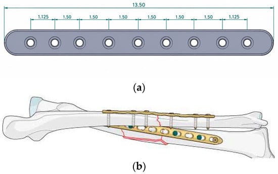
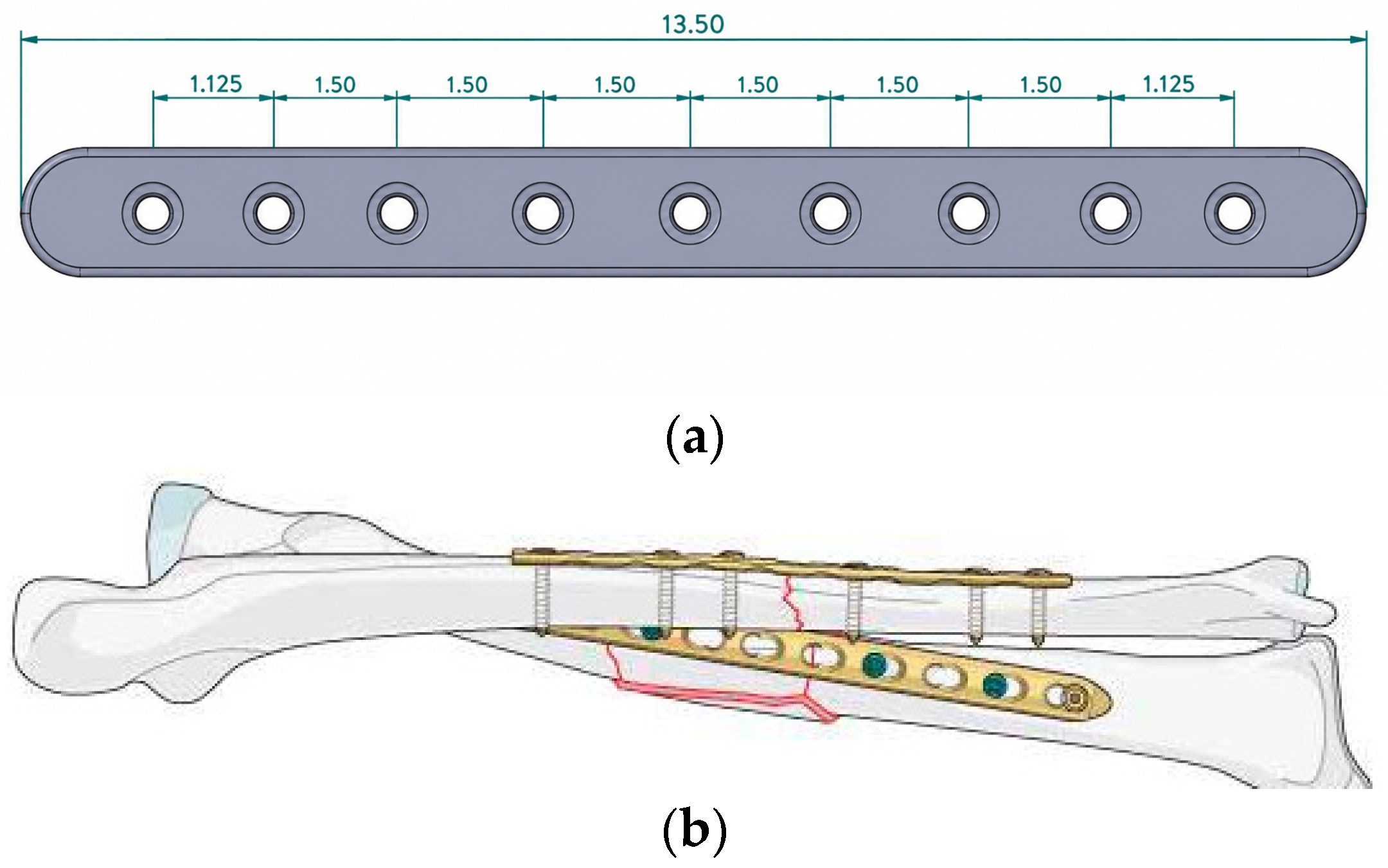
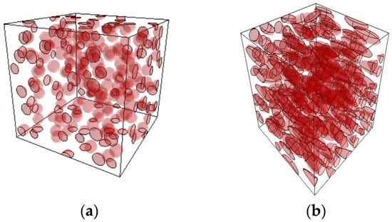
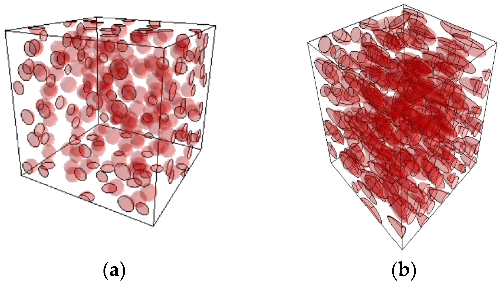
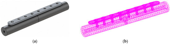
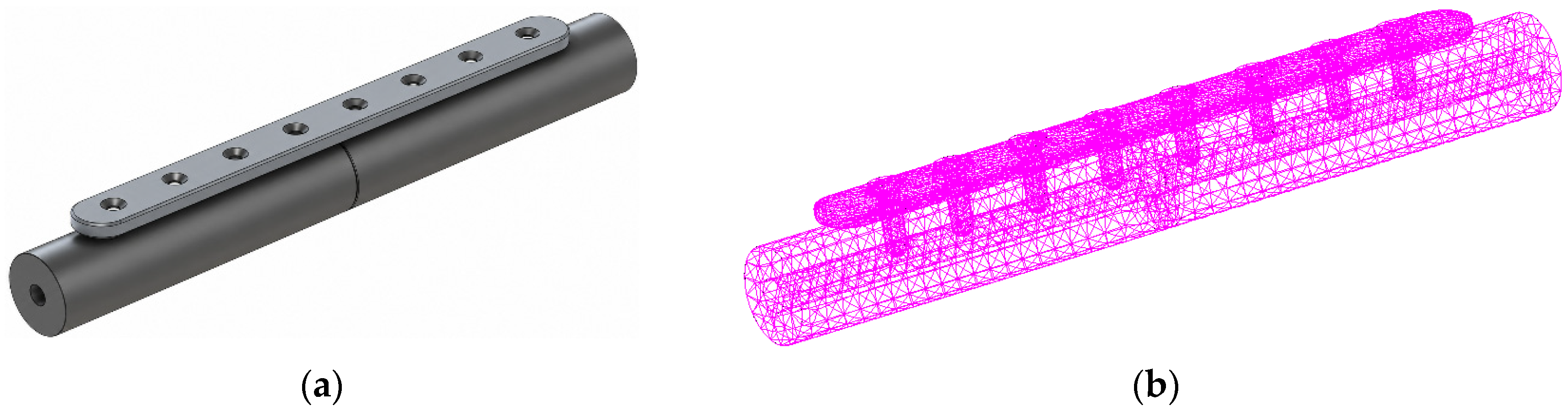
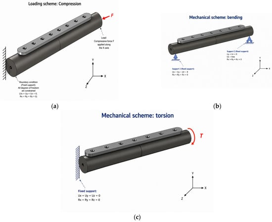
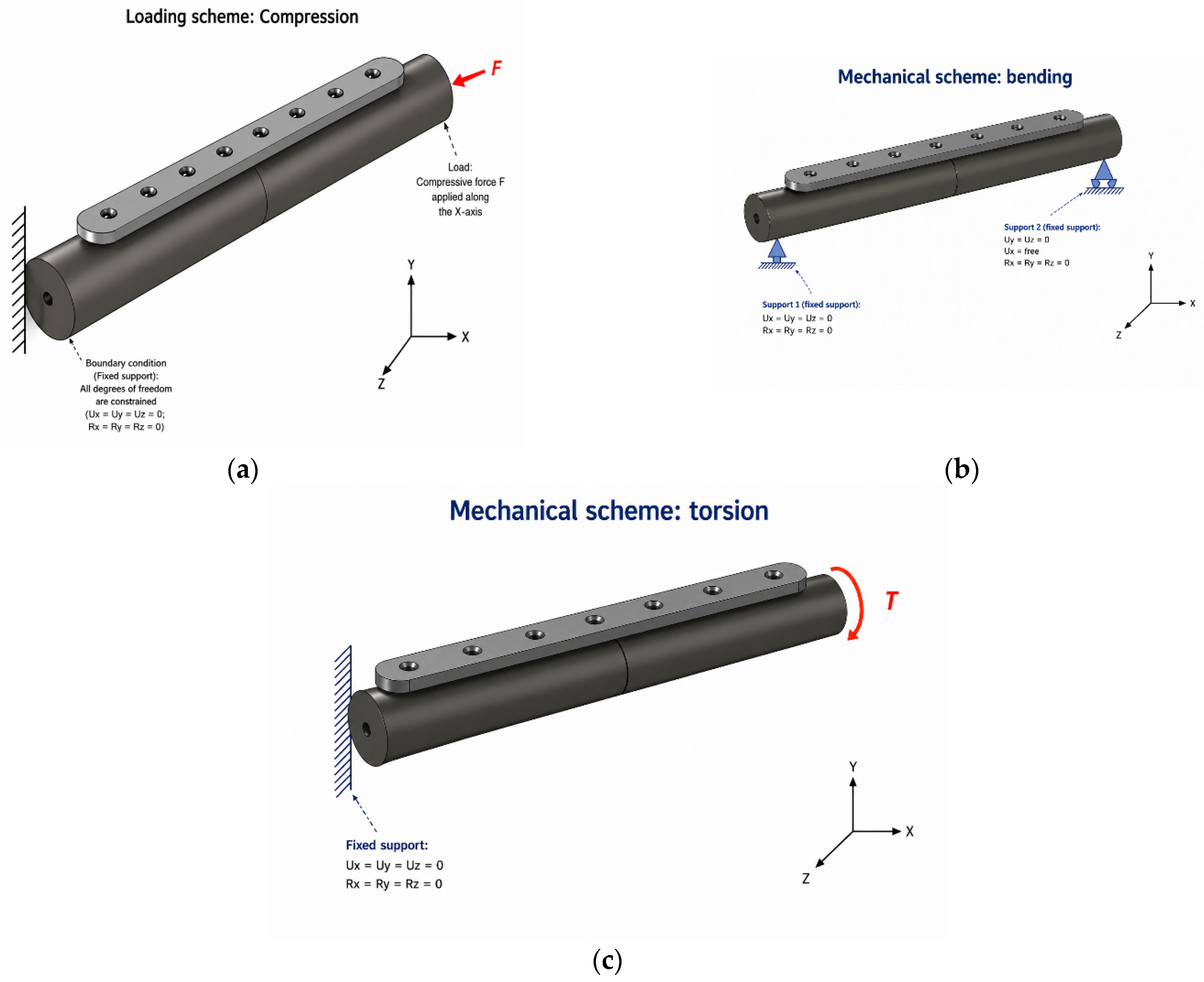
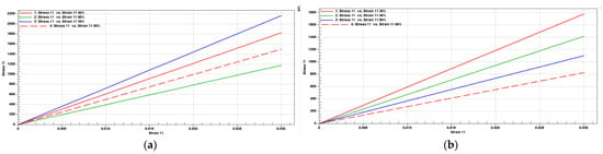
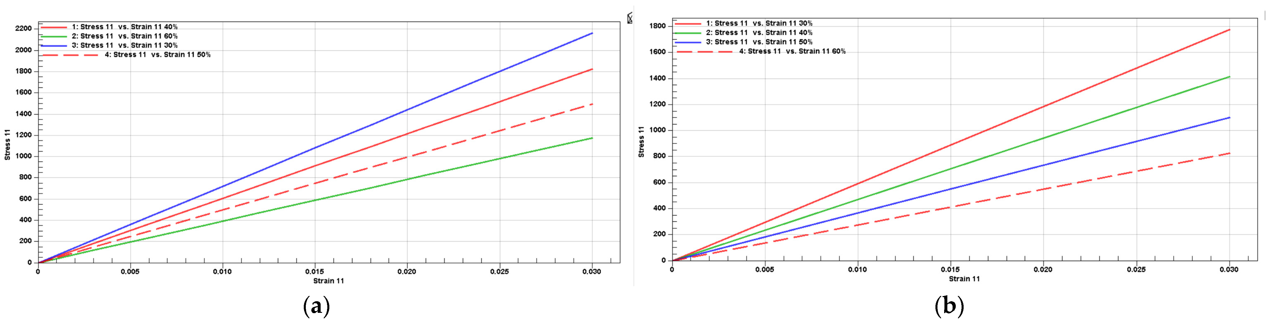
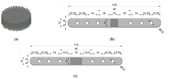
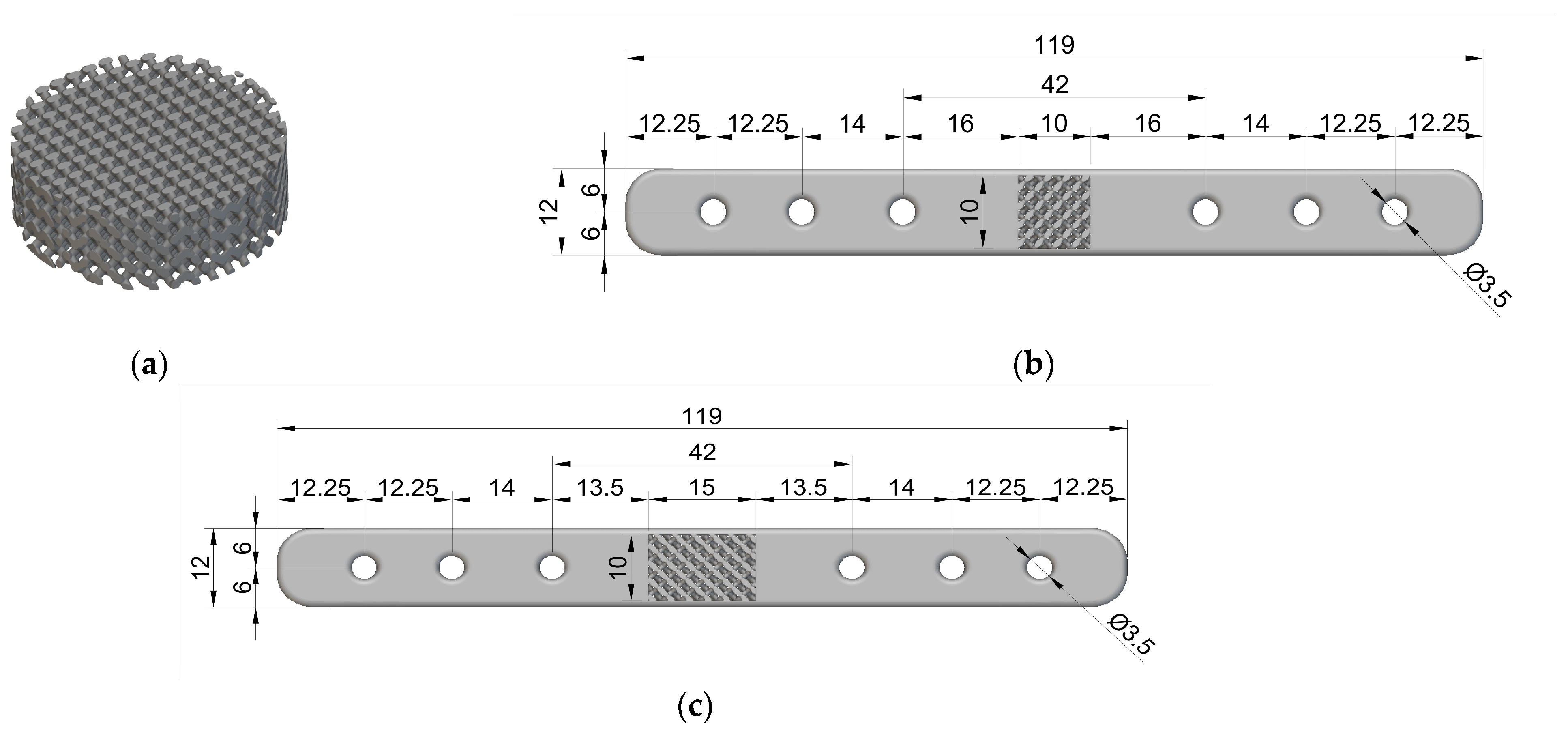
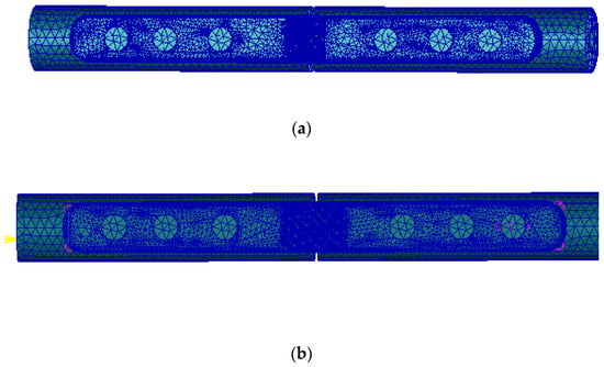
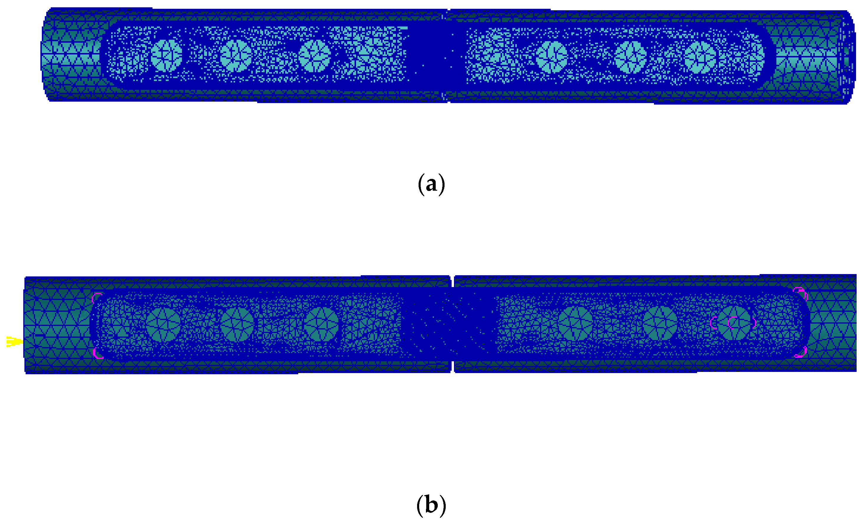
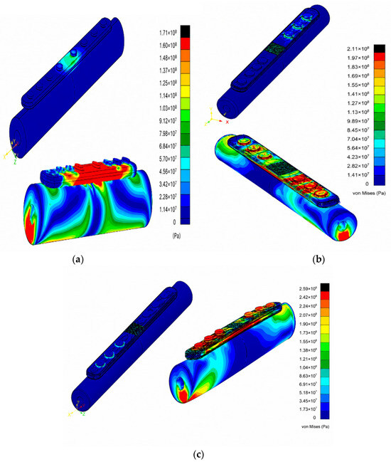
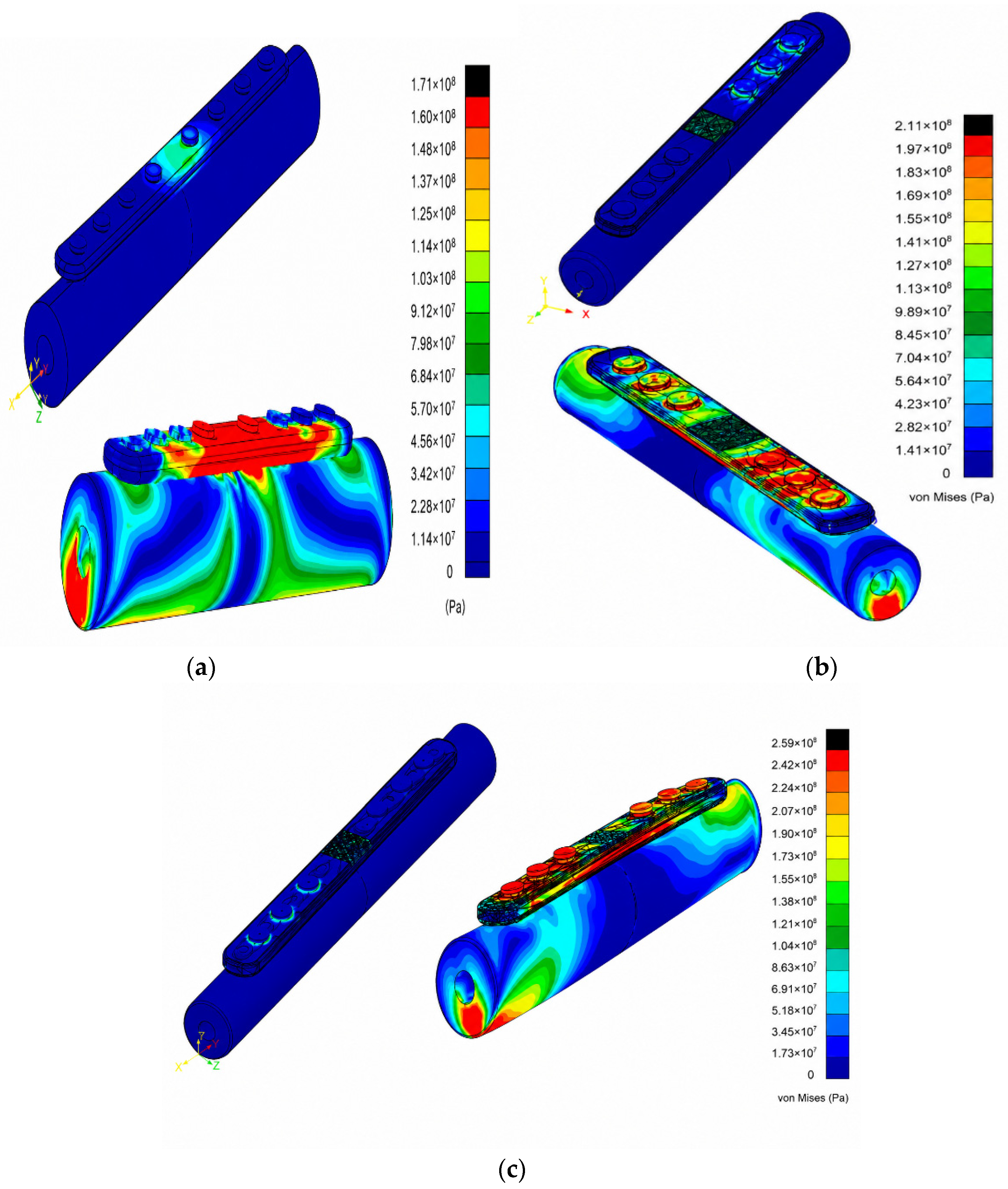
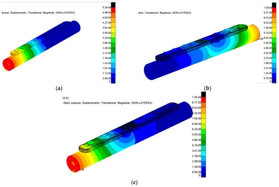
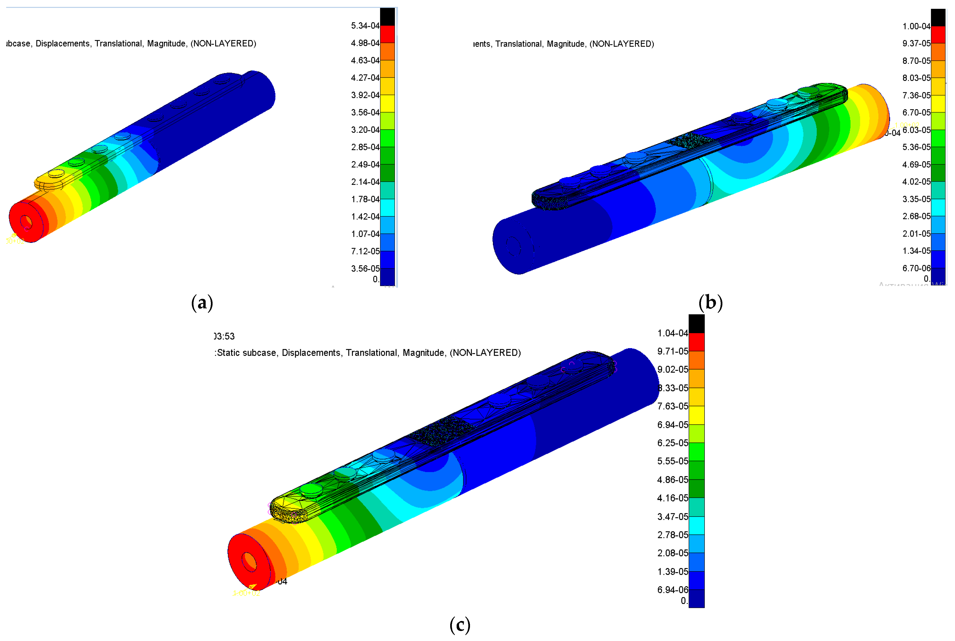
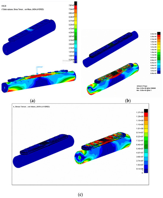
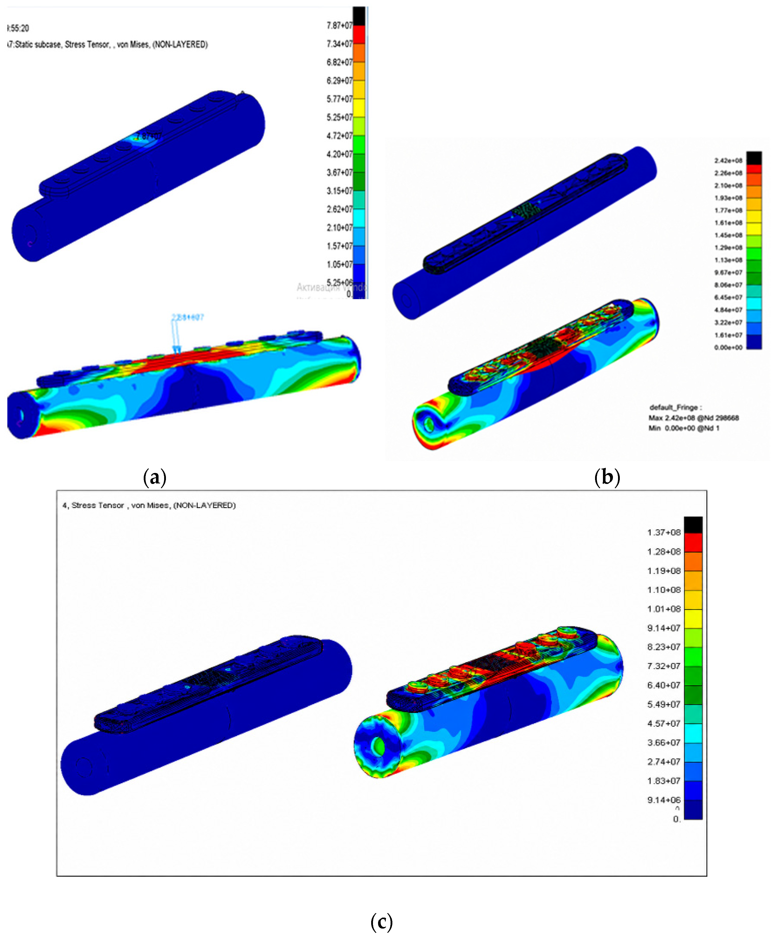
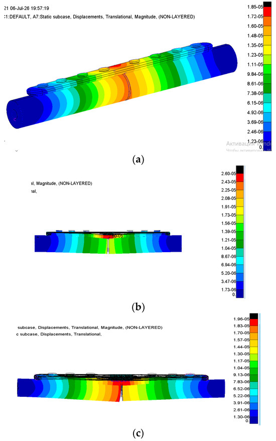
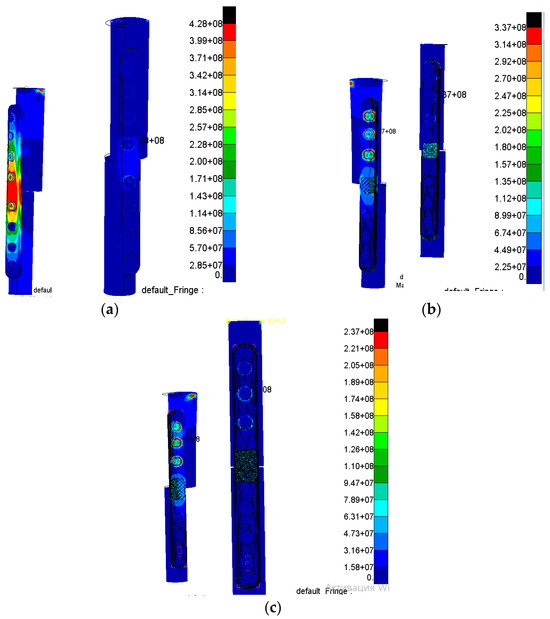
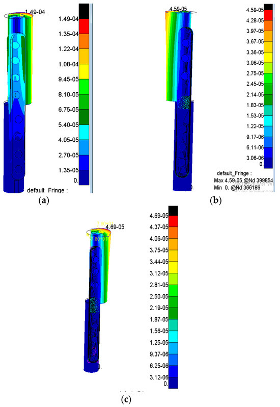
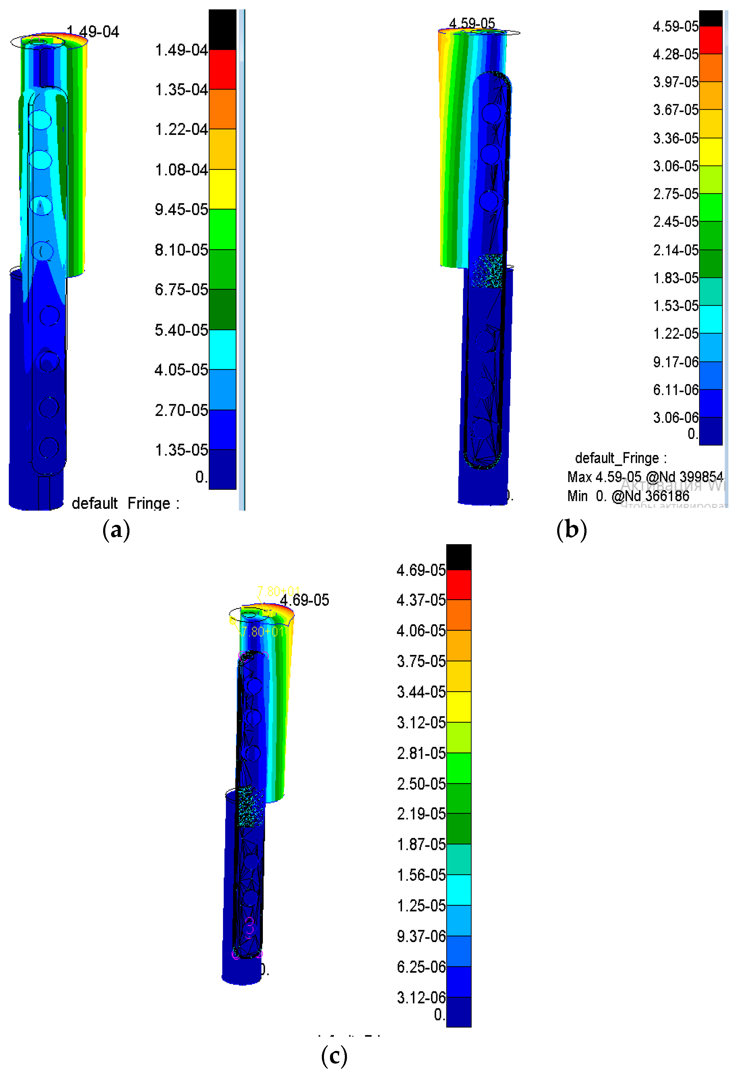
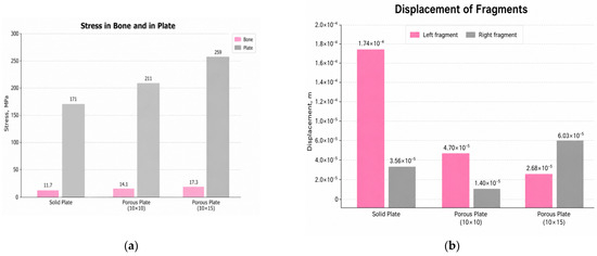
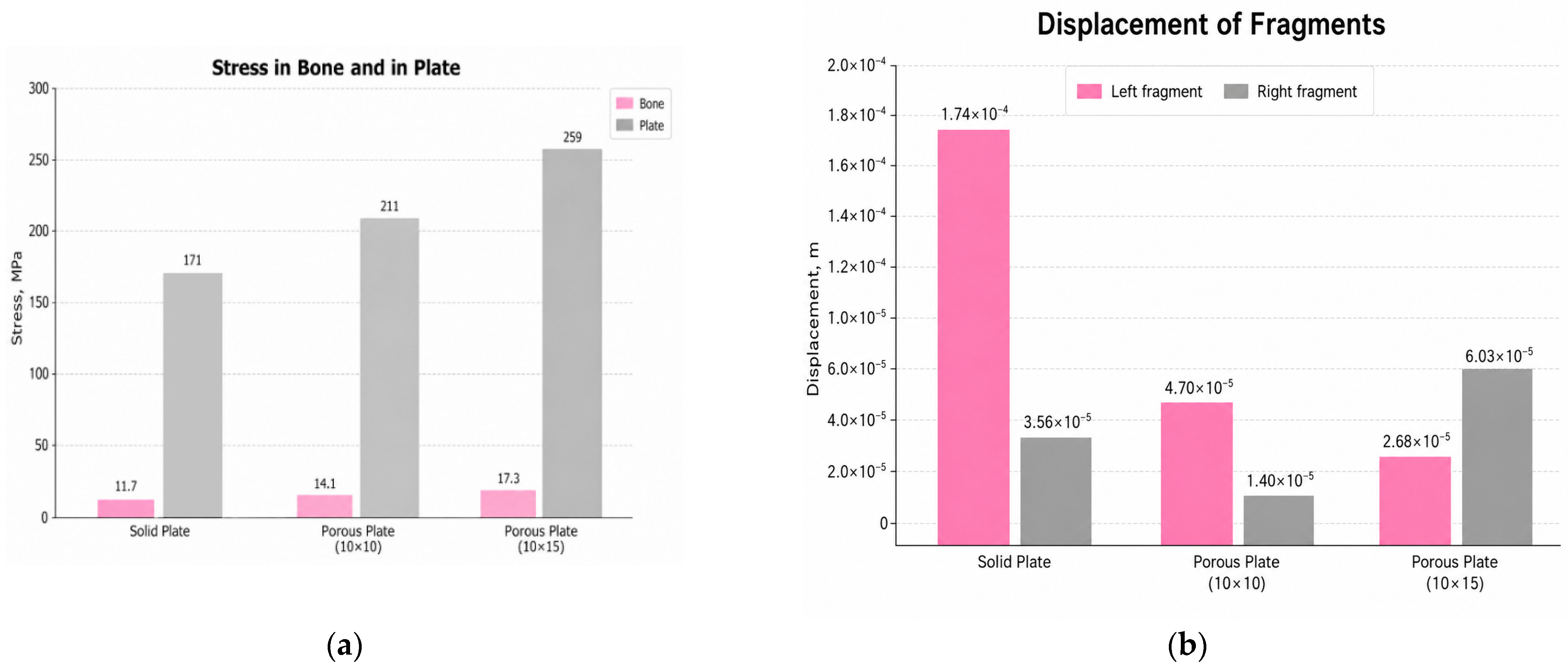
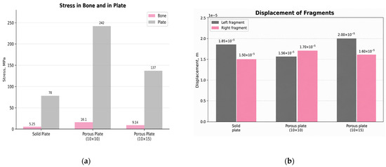
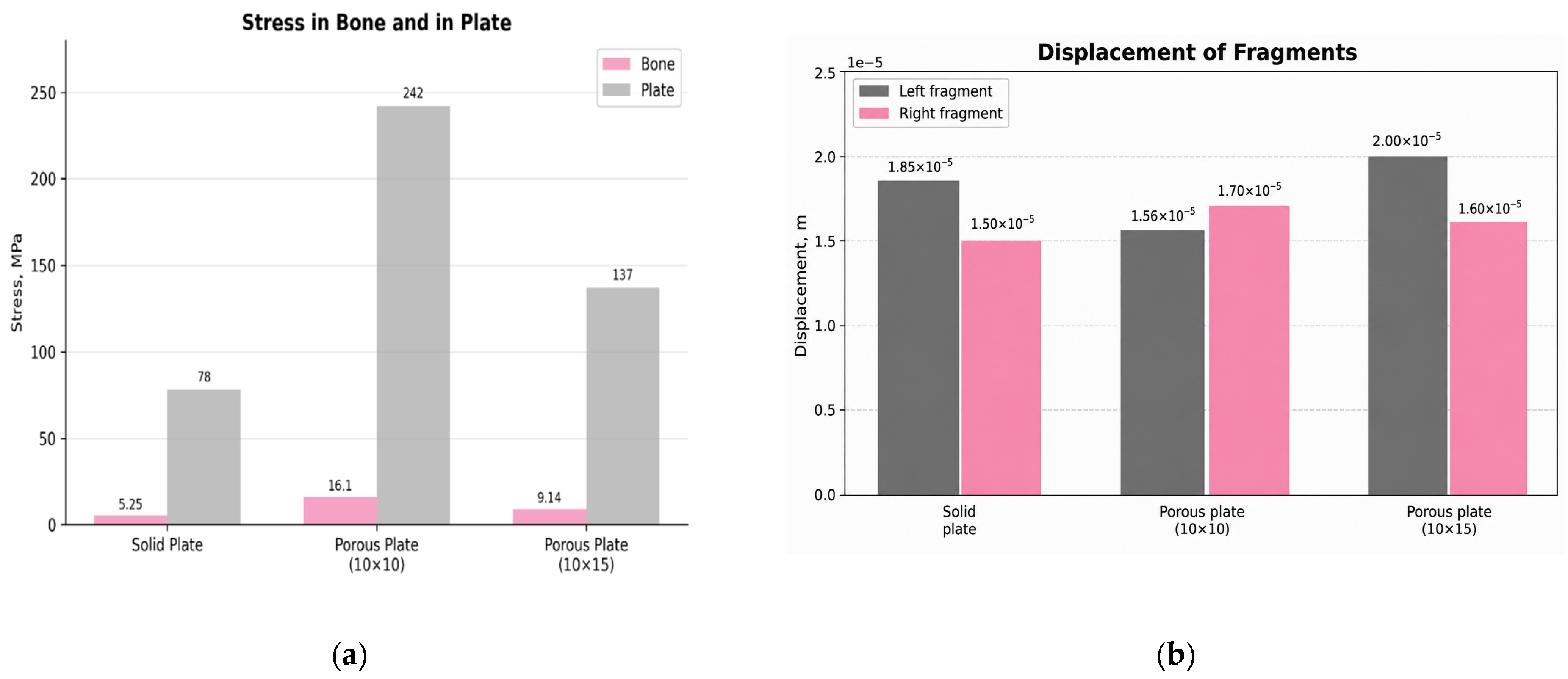
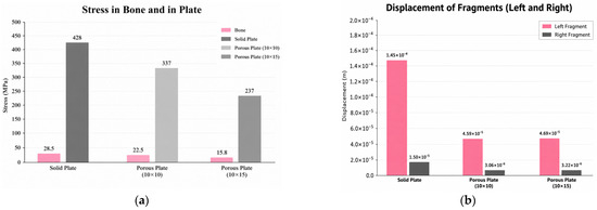
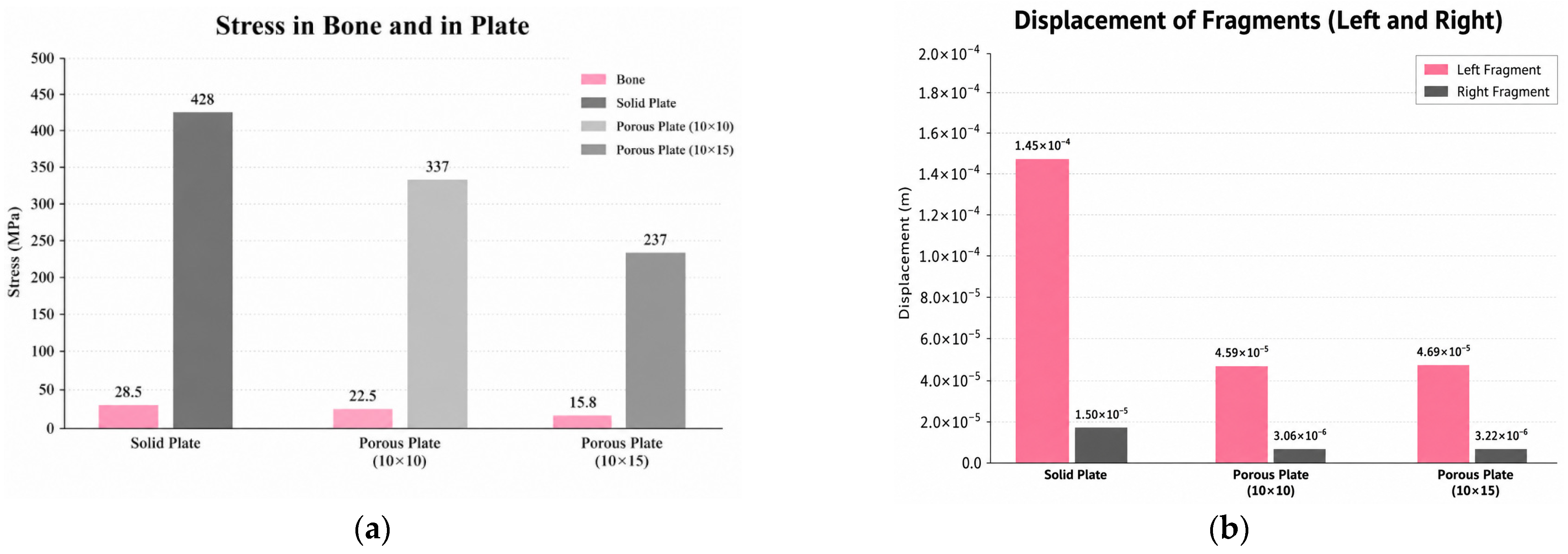
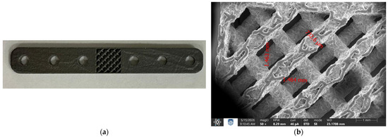
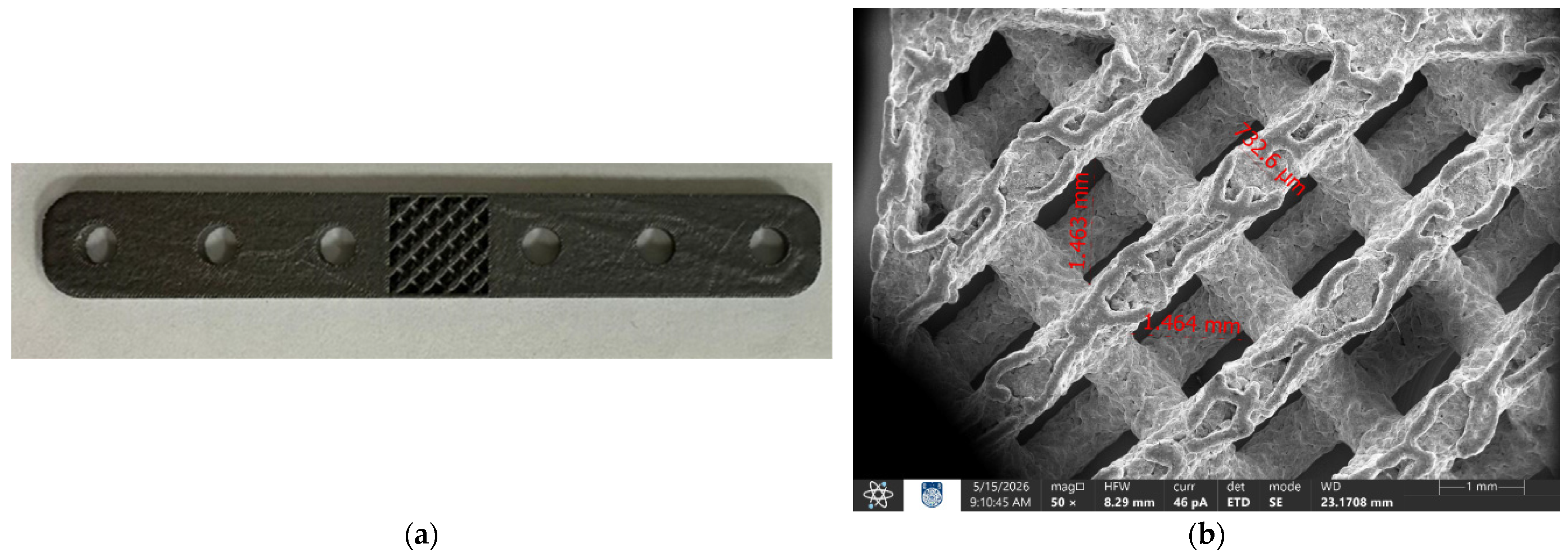

Disclaimer/Publisher’s Note: The statements, opinions and data contained in all publications are solely those of the individual author(s) and contributor(s) and not of MDPI and/or the editor(s). MDPI and/or the editor(s) disclaim responsibility for any injury to people or property resulting from any ideas, methods, instructions or products referred to in the content. |
© 2026 by the authors. Licensee MDPI, Basel, Switzerland. This article is an open access article distributed under the terms and conditions of the Creative Commons Attribution (CC BY) license.