


Abstract
High-frequency induction hardening enhances the surface wear resistance and contact fatigue life of high-speed linear guides, but simultaneously produces an inhomogeneous, layered cross-sectional structure comprising a high-strength, low-ductility outer hardened layer and a low-strength, high-ductility inner core. This structural heterogeneity renders conventional straightening stroke prediction models—predicated on homogeneous material assumptions—fundamentally inadequate. Moreover, the iterative trial-bending operations ubiquitous in industrial practice progressively accumulate plastic strain, causing guide rails to exhibit erratic positive-to-negative deflection reversal during sequential straightening passes. To address these critical challenges, this study proposes a novel two-stage hybrid straightening strategy based on inverse finite element analysis (FEA) and closed-loop experimental feedback. An equivalent hardened layer depth (HD0) is introduced as a parametric descriptor to construct a layered elastoplastic finite element model, and an inverse simulation strategy is developed to generate a comprehensive three-dimensional stroke–residual deflection prediction dataset encompassing both vertical and lateral straightening conditions across multiple support spans. Displacement-controlled three-point bending experiments validate the layered model and elucidate the mechanism by which cumulative plasticity progressively amplifies cross-sectional plastic sensitivity under repeated loading. Grounded in this physical insight, a hybrid straightening algorithm is formulated, combining dataset-driven initial stroke prediction for rapid large-deformation elimination with an upper-bound constraint and a measurement-feedback-driven sequential reduction compensation scheme for fine-tuning. Comparative experiments demonstrate that the proposed strategy effectively suppresses the oscillatory over-straightening characteristic of conventional empirical trial-and-error approaches, consistently reducing residual deflection below 0.05 mm within two to three loading cycles. This work bridges the gap between theoretical simulation and the complex physical state of actual machining, substantially improving both the efficiency and precision of straightening for guide rails with induction-hardened layers.
1. Introduction
As a core transmission and guidance component in precision machinery, the straightness error of high-speed linear guides directly affects the motion accuracy and operational reliability of the entire system [1,2,3]. To satisfy the stringent requirements for wear resistance and contact fatigue life, the guide rail surfaces are typically subjected to high-frequency induction hardening followed by low-temperature tempering [4,5,6]. This heat treatment cycle produces, along the depth direction of the cross-section, a non-homogeneous layered structure comprising a high-strength, low-ductility hardened case and a low-strength, high-ductility tough core [7]. Due to the pronounced differences in yield strength and strain hardening coefficient between these two layers, the layered architecture fundamentally alters the elastoplastic evolution and springback behavior of the cross-section during bending, posing formidable challenges to high-precision straightening [8,9,10].
Existing research on the bending and precision straightening of metallic profiles classifies straightening theories primarily according to the control mode: curvature-straightening force models based on force-load control, and deflection-straightening stroke models based on displacement-load control [11,12,13]. Regarding stroke selection and springback prediction, the methodologies have rapidly evolved from conventional analytical and empirical models [14,15,16,17] to advanced numerical and intelligent approaches. Specifically, for materials with complex heterogeneous microstructures, advanced finite element analysis (FEA) has been increasingly employed in recent years to characterize the highly nonlinear springback behavior of layered, tailor-welded, or gradient-hardened components [18,19,20]. Specifically regarding layered or case-hardened steels, recent findings have demonstrated that the strength mismatch between the hardened surface and the ductile core dramatically alters the yield propagation and neutral axis shift during bending [21]. Furthermore, while the cumulative plasticity and the Bauschinger effect induced by repeated reverse bending have been extensively explored, in general, sheet metal forming and cyclic loading [22,23], their specific coupling with the steep hardness gradients in induction-hardened linear guides remains inadequately addressed in current straightening models.
Concurrently, to overcome the efficiency bottlenecks of theoretical and FEA calculations, data-driven methods have gained significant traction. Recent advancements highlight the integration of complex algorithms to map the highly nonlinear relationship between bending strokes and elastic recovery. For instance, sophisticated machine learning frameworks, including support vector regression (SVR) optimized by metaheuristic algorithms [24] and deep learning models utilizing point series [25], have been developed to enhance prediction accuracy. Furthermore, stress-aware graph neural networks (GNNs) [26] and physics-informed neural networks (PINNs) [27] have been introduced to incorporate physical constraints into prediction models, while experimental-based predictive approaches continue to evolve for complex free-bending scenarios [28].
Despite the exceptional predictive capabilities of these intelligent approaches under standardized conditions, their direct application to the multi-pass straightening of induction-hardened linear guides confronts significant theoretical limitations and engineering challenges. First, most mechanical models are founded on the assumption of material homogeneity and do not systematically account for the interference of the quenched layered structure on the cross-sectional bending stiffness and yield propagation path. Second, although conventional forward FEA simulations offer high computational accuracy, the prohibitive computational costs make exhaustive enumeration of the initial deflection conditions impractical. Most critically, existing predictive theories and intelligent algorithms focus predominantly on improving the accuracy of single-pass bending, and rarely investigate the cumulative plasticity effect induced by the repeated loading–unloading cycles inherent in actual multi-step correction processes. Once the guide rail undergoes initial yielding, its mechanical baseline shifts fundamentally. If subsequent correction passes are still guided by theoretical predictions derived from a pristine, load-history-free state, severe over-straightening is virtually inevitable.
While manufacturers use geometric accuracy standards (e.g., ISO 14728) [29] for final product acceptance, they currently lack standardized predictive solutions for the straightening process itself. To overcome these theoretical limitations and explicitly aim to bridge this industrial gap, this paper proposes a hybrid straightening strategy for linear guide rails with hardened layers based on inverse finite element modeling. An equivalent hardened layer depth (HD0) is introduced as a parametric descriptor to construct a layered finite element model. An inverse simulation strategy is then employed to build a comprehensive span–stroke–residual deflection prediction dataset covering both vertical and lateral straightening conditions across multiple support spans, thereby substantially reducing the dimensionality of the complex nonlinear solution. The model accuracy is subsequently verified through experiments, and the cumulative plasticity evolution induced by repeated bending is thoroughly analyzed. Building on this physical understanding, a two-stage hybrid straightening algorithm combining initial-pass prediction with subsequent constraint-based compensation is proposed. This approach aims to fundamentally resolve the persistent engineering challenges of low straightening efficiency and susceptibility to overcorrection by seamlessly integrating the efficient initial-value prediction capability of simulation data with the precision iterative constraints afforded by measured experimental feedback.
2. Inverse Finite Element Modeling and Prediction Dataset Construction
During the three-point straightening process of linear guides, the cross-section undergoes complex elastoplastic loading and subsequent springback upon unloading. To accurately quantify the influence of the hardened layer on the bending response and to provide a sound basis for actual straightening operations, this section establishes a finite element model that fully accounts for the layered characteristics of the hardened case and proposes an inverse simulation strategy for constructing a stroke–residual deflection prediction dataset applicable to multiple support span conditions.
2.1. Mechanical Characterization and Layered Modeling of Guide Rails with Hardened Layers
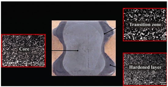
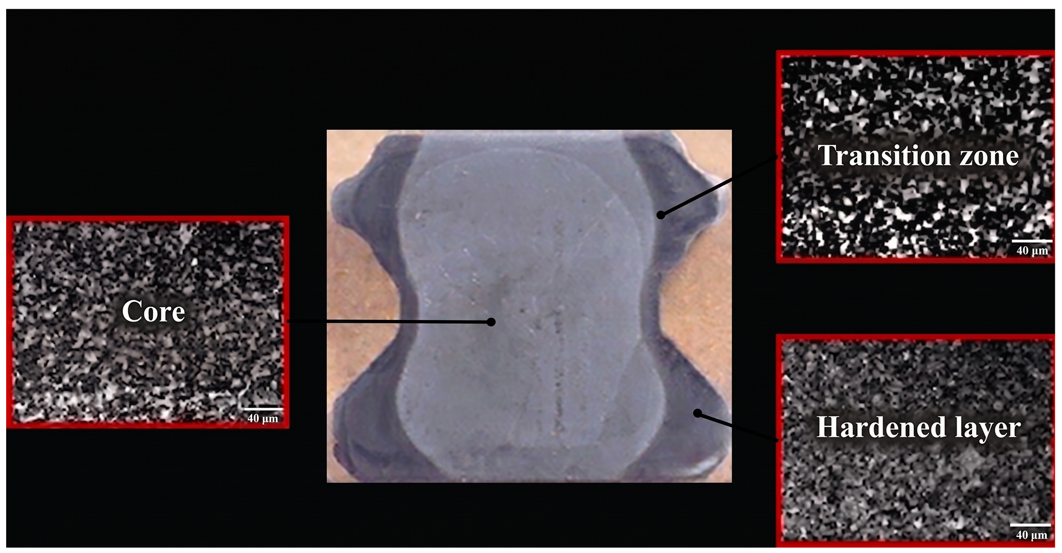
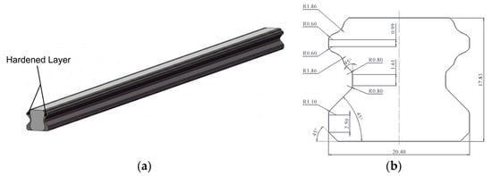
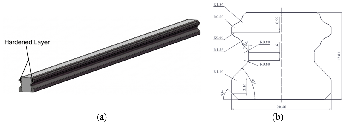
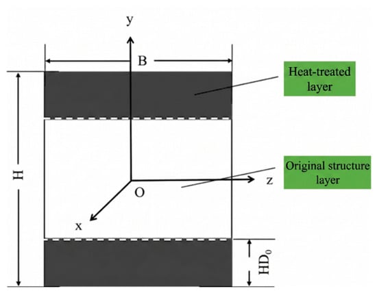
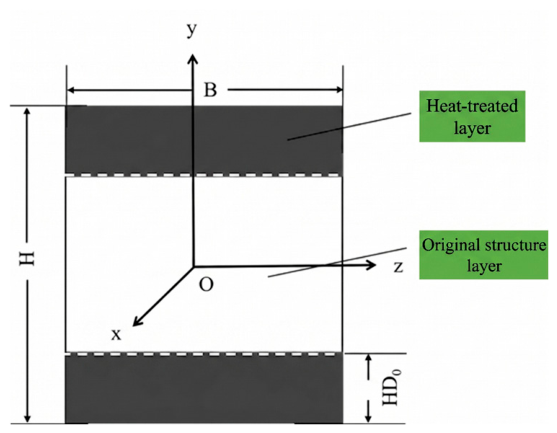
After high-frequency induction hardening, high-speed linear guide rails develop a surface hardened layer composed of tempered martensite, while the core retains a ferritic-pearlitic microstructure. Following standard metallographic preparation procedures—including precision grinding, polishing, and etching with a 4% nital solution—optical microscopy observations were conducted. As shown in Figure 1, these observations reveal a distinct transition zone between the hardened layer and the core, forming a typical heterogeneous layered structure. Microhardness testing indicates a nonlinear gradient decrease in hardness from the surface toward the center. In accordance with established regulatory standards (e.g., ISO 18203), regions exhibiting a hardness above 550 HV are defined as the effective hardened layer [30]. To provide a clear visual representation of the subject, the detailed cross-sectional geometry and dimensions of the GH20 linear guide are illustrated in Figure 2. Because of the complex cross-sectional geometry of the guide rail, the actual induction-hardened boundary exhibits a highly irregular spatial distribution. To enhance the engineering generality of the finite element model, this study introduces a parametric equivalent hardened layer depth (Figure 3), HD0, based on the principle of cross-sectional area equivalence:
where Ahard denotes the total area of the actually hardened zone in the cross-section, and Psurface denotes the envelope perimeter of the quenched surface. For the GH20-type guide rail, experimental measurement yields an equivalent depth of HD0 = 3.88 mm. This parameter effectively transforms a complex microstructural gradient into a parametrically definable layered geometric model, substantially mitigating the risk of mesh distortion in nonlinear contact computations.
Figure 1.
Macroscopic cross-sectional morphology of the induction-hardened linear guide.
Figure 2.
GH20 High-Speed Linear Guideway. (a) Schematic of the test specimen. (b) Schematic of cross-sectional dimensions.
Figure 3.
Schematic illustration of the equivalent hardened layer depth.
2.2. Inverse Simulation Strategy and Construction of the Prediction Dataset
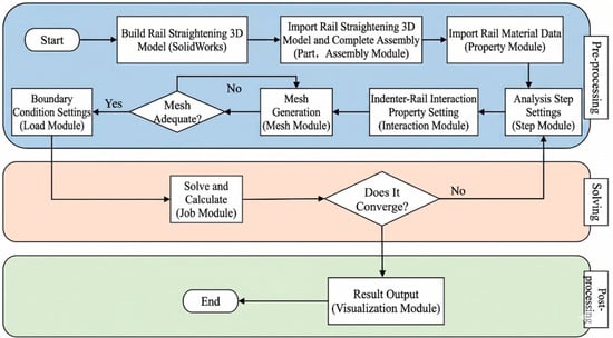
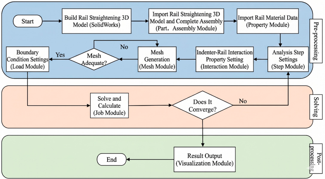
Conventional forward simulation follows the sequence: prescribe initial deflection—apply straightening stroke—compute residual deflection. However, the initial deflections of guide rails awaiting correction in industrial settings are highly stochastic, and the computational cost of exhaustive forward enumeration is enormous, precluding the construction of a universally applicable process-guidance dataset. To circumvent this limitation, this study proposes an inverse simulation strategy, as illustrated in Figure 4. For an ideally straight guide rail model with strictly zero initial deflection (δ0 = 0), a series of discrete straightening strokes S are applied under a fixed support span, and the stabilized residual deflection δ∑ upon complete unloading is recorded. Since the material follows a stable elastoplastic hardening criterion throughout the monotonic loading–unloading cycle—with the rate of plastic deformation growth consistently exceeding that of elastic recovery—a strict monotonically increasing mapping exists between residual deflection and straightening stroke. This strategy elegantly transforms the inherently ill-posed inverse problem of determining the required stroke from a known deflection into the well-posed direct problem of computing the residual deflection from a prescribed stroke, dramatically reducing the dimensionality of the nonlinear solution and providing the theoretical basis for constructing a universal prediction dataset.
Figure 4.
Flowchart of the finite element simulation for three-point displacement straightening.
To cover the full range of practical production requirements, denser sampling was performed within the sensitive short-span sub-range of 150–250 mm across an overall span range of 150–600 mm. A complete straightening stroke prediction dataset was thereby constructed through batch inverse simulation. Upon extraction of the simulation results, a three-dimensional response surface was assembled with support span L and straightening stroke S as independent variables, and residual deflection δ∑ as the dependent variable. In practical engineering deployment, once the actual initial deflection δ0 of the rail to be straightened is measured and the span is selected, the system retrieves the two nearest bounding data points, (δlower, Slower) and (δupper, Supper), from the dataset corresponding to the chosen span. Since adjacent data points are closely spaced and the response is monotonic, a linear interpolation inversion algorithm is employed to compute the predicted straightening stroke Spre:
This interpolation inversion formula serves as the critical bridge between finite element discrete data and practical shop-floor deployment. The predicted stroke obtained from this dataset is used directly as the baseline reference input for the initial straightening stage in the subsequent hybrid straightening strategy.
2.3. Material Characterization and Finite Element Model Configuration
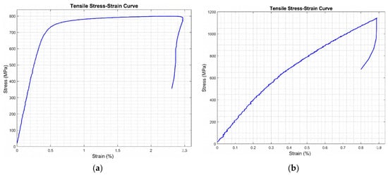
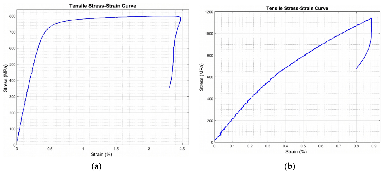
To faithfully reproduce the heterogeneous mechanical behavior of the guide rail cross-section following quench hardening, the true stress–strain curves for both the hardened layer and the core material of the GH20 guide rail were obtained through standard room-temperature uniaxial tensile tests, as shown in Figure 5. Since the straightening process involves quasi-static monotonic loading with a comparatively limited extent of plastic deformation, a bilinear, layered elastoplastic constitutive model was adopted to simplify the material description. The experimental data reveal pronounced differences in mechanical properties between the two material layers. The core material exhibits the characteristic behavior of medium-carbon steel: low yield strength and mild hardening (yield strength: 749 MPa; tensile strength: 799 MPa; hardening coefficient: λ = 0.015). In contrast, the hardened layer, strengthened by the martensitic microstructure through solid-solution strengthening, displays a high yield strength (961 MPa). As is typical for martensite, its overall plastic strain margin is relatively limited. However, its apparent strain hardening coefficient (λ = 0.418) is significantly higher than that of the core. This stark contrast—where the hardening coefficient of the hardened layer is approximately 28 times that of the core—constitutes the constitutive root cause of the pronounced springback nonlinearity observed in guide rails with hardened layers. While advanced kinematic models could address secondary effects like the Bauschinger phenomenon, the current two-layer bilinear isotropic model is widely adopted as an efficient and practical engineering standard to capture the primary macroscopic yielding behavior during straightening.
Figure 5.
True stress–strain curves: (a) core material; (b) hardened layer material.
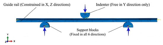
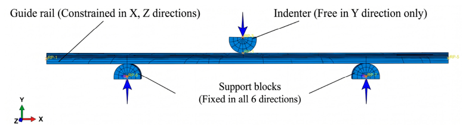
In terms of geometric modeling, the previously established ultrasonic non-destructive testing results were used to directly introduce the equivalent hardened layer depth HD0 = 3.88 mm as a substitute for the geometrically complex, high-degree-of-freedom actual quenched boundary profile, thereby serving as the unified geometric input for the parametric layered cross-section model. Separate three-dimensional solid models were created for the hardened layer and the core in ABAQUS (Figure 6), with tie constraints applied at their interface to enforce kinematic compatibility and eliminate interlayer slippage. The guide rail body was discretized using C3D8R reduced-integration hexahedral elements. To ensure the reliability of the finite element results and optimize computational cost, a mesh convergence study was conducted. Three global mesh sizes—1 mm, 2 mm, and 4 mm—were evaluated under an identical straightening condition. The comparative analysis revealed that refining the mesh from 4 mm to 2 mm resulted in a significant change in the predicted residual deflection, indicating inadequate accuracy of the coarse mesh. However, further refining the mesh from 2 mm to 1 mm yielded a relative difference in the maximum residual deflection of less than 1.5%, while the computational time increased by approximately 4 times. Consequently, a global mesh size of 2 mm was rigorously selected to balance computational accuracy and efficiency. Furthermore, to suppress the spurious zero-energy deformation modes (hourglass effect) typically associated with reduced-integration elements under the high strain gradients of the indenter contact zone, enhanced hourglass control was activated in the solver. Post-analysis energy checks confirmed that the artificial strain energy (ALLAE) remained strictly below 2% of the total internal energy (ALLIE) throughout the loading cycle, thereby guaranteeing the physical validity of the local contact deformation. C3D8R elements were specifically selected to prevent volumetric locking during massive plastic yielding and to ensure stable convergence in complex contact modeling. The loading indenter and support blocks (typical elastic modulus ~210 GPa) were modeled as analytical rigid bodies, as their local elastic deformations are negligible compared to the macroscopic bending of the guide rail (core modulus 206 GPa). Surface-to-surface contact was defined between the rigid bodies and the guide rail surface, with hard contact in the normal direction and a penalty-function friction formulation in the tangential direction, using a friction coefficient of 0.3.
Figure 6.
Three-dimensional solid finite element model of the linear guide rail.
2.4. Comparative Analysis of Hardened Layer Effects Under Vertical and Lateral Straightening Conditions
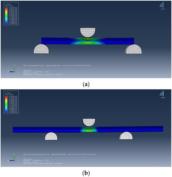
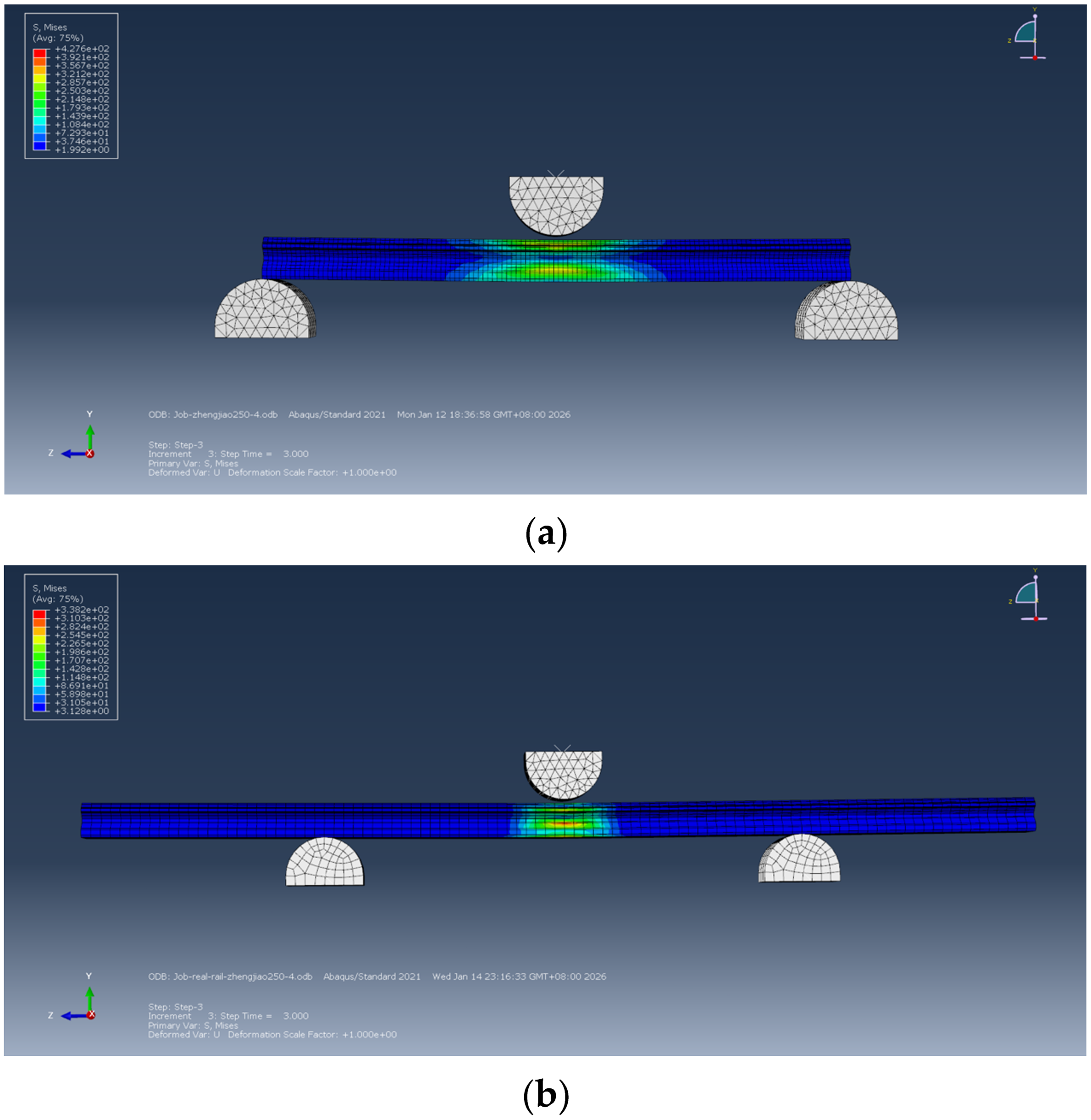
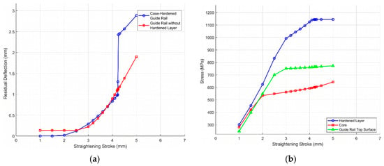
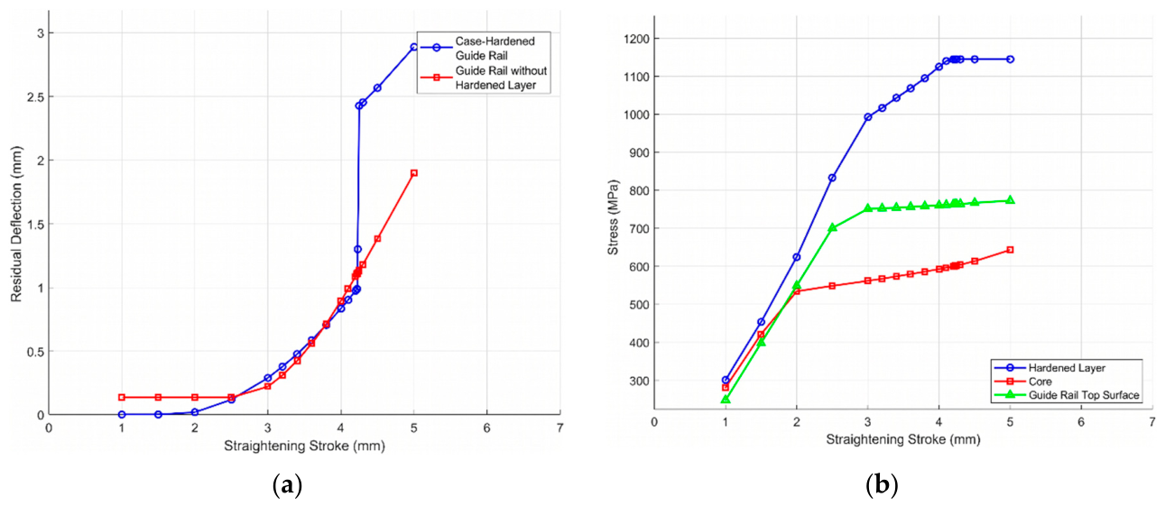
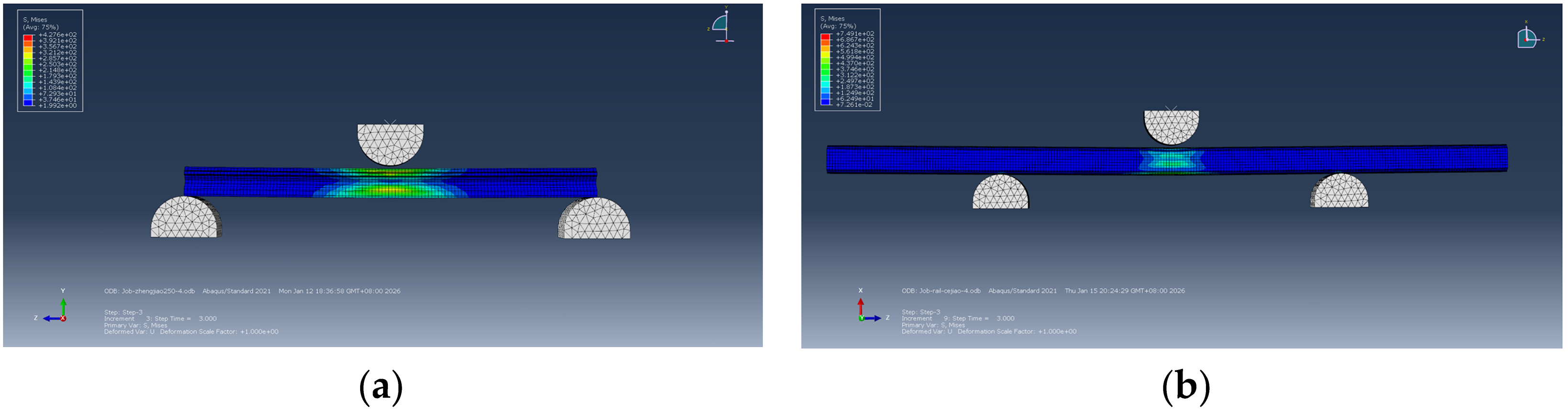
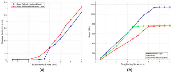
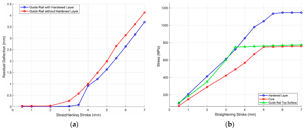
Under vertical straightening conditions (Figure 7), the hardened layer is located at the upper and lower surfaces of the cross-section—the regions of maximum bending tensile and compressive stress. At the onset of loading, the high-hardness hardened layer carries the overwhelming majority of the applied bending moment. As the straightening stroke S increases, however, the strain hardening coefficient λ2 of the hardened layer—nearly 28 times that of the core—drives a far more rapid accumulation of internal stress than occurs in the core. Based on the simulation data in Table 1, the stroke–residual deflection comparison curve plotted in Figure 8 shows that once the stroke reaches a specific critical value, the maximum stress within the hardened layer first attains its tensile strength limit of 1145 MPa, instantaneously saturating its load-bearing capacity. At this juncture, the instantaneous equivalent stress generated in the core material is approximately 600 MPa. Although this value has not yet reached the core’s intrinsic yield strength of 749 MPa (as defined in Section 2.3), it is fundamentally insufficient to absorb the massive additional bending moment abruptly transferred from the saturated hardened layer. This imbalance triggers a sudden loss of overall cross-sectional bending stiffness. This mechanical instability manifests in the stroke–residual deflection curve as a pronounced step-like discontinuous jump in residual deflection, which represents a genuine physical collapse of cross-sectional stiffness rather than a numerical non-convergence.
Figure 7.
Stress contour plots of the guide rail under vertical straightening: (a) without hardened layer; (b) with hardened layer.
Table 1.
Simulation data for linear guide rails in the vertical straightening condition without and with hardened layers.
Figure 8.
Effect of the hardened layer on the straightening response under vertical conditions: (a) stroke–residual deflection curve; (b) stroke–stress curve.
Under lateral straightening conditions, comparison curves of straightening stroke versus residual deflection for both model variants were plotted based on the data in Table 2. In this configuration, the hardened layer is distributed along the two lateral edges of the cross-section, at considerable distance from the bending neutral axis. Simulation results of the stress evolution shown in Figure 9 reveal that the plastic zone advances steadily and symmetrically from both sides of the neutral axis toward the full cross-section, with the hardened layer and the core approaching their respective strength limits almost synchronously, thus avoiding any abrupt discontinuity in stress transfer. As quantitatively demonstrated in Figure 10, owing to the supporting effect of the hardened layer’s exceptionally high yield strength, the initial plastic stroke under lateral straightening is extended by 26.6% (increasing from 3.50 mm without the hardened layer to 4.43 mm with the hardened layer) relative to the homogeneous material assumption, compared with a marginal increase of only 2.7% (increasing from 2.64 mm to 2.71 mm) under vertical straightening. Accordingly, the stroke–residual deflection relationship for lateral straightening maintains a smooth, monotonically increasing trend across the entire loading range, with no evidence of the step-like instability observed in the vertical case.
Table 2.
Simulation data for linear guide rails in the lateral straightening condition without and with hardened layers.
Figure 9.
Stress contour plots of the guide rail under lateral straightening: (a) without hardened layer; (b) with hardened layer.
Figure 10.
Effect of the hardened layer on the straightening response under lateral conditions: (a) stroke–residual deflection curve; (b) stroke–stress curve.
The mechanistic analysis above reveals fundamental physical distinctions in the precision straightening of guide rails with hardened layers. Under vertical straightening, the system exhibits extremely high stroke sensitivity in the vicinity of the critical transition point, making it acutely prone to over-straightening and rebound. Under lateral straightening, by contrast, a wider elastoplastic transition band and a more stable deformation resistance are observed. This finding establishes the imperative to construct independent, high-density nonlinear prediction datasets for both loading configurations to serve as reliable theoretical references for the subsequent accurate elimination of large deflections.
3. Experimental Validation and Identification of the Cumulative Plasticity Problem
To verify the physical accuracy of the layered finite element model and to investigate the influence of repeated loading on the bending response of guide rails during actual machining, a displacement-controlled three-point bending test platform was established, and comparative experiments under single and repeated loading were conducted. This section reveals the evolution of cumulative plasticity in guide rails subjected to repeated bending, thereby exposing the inherent limitations of relying solely on theoretical prediction in engineering applications.
3.1. Experimental Configuration and Model Validation
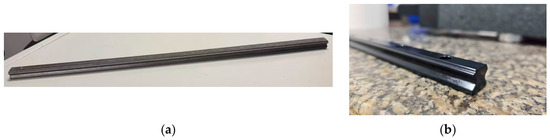
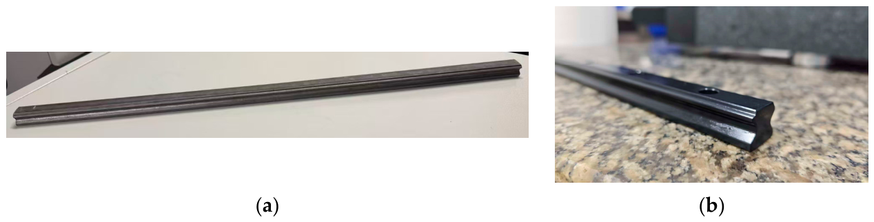
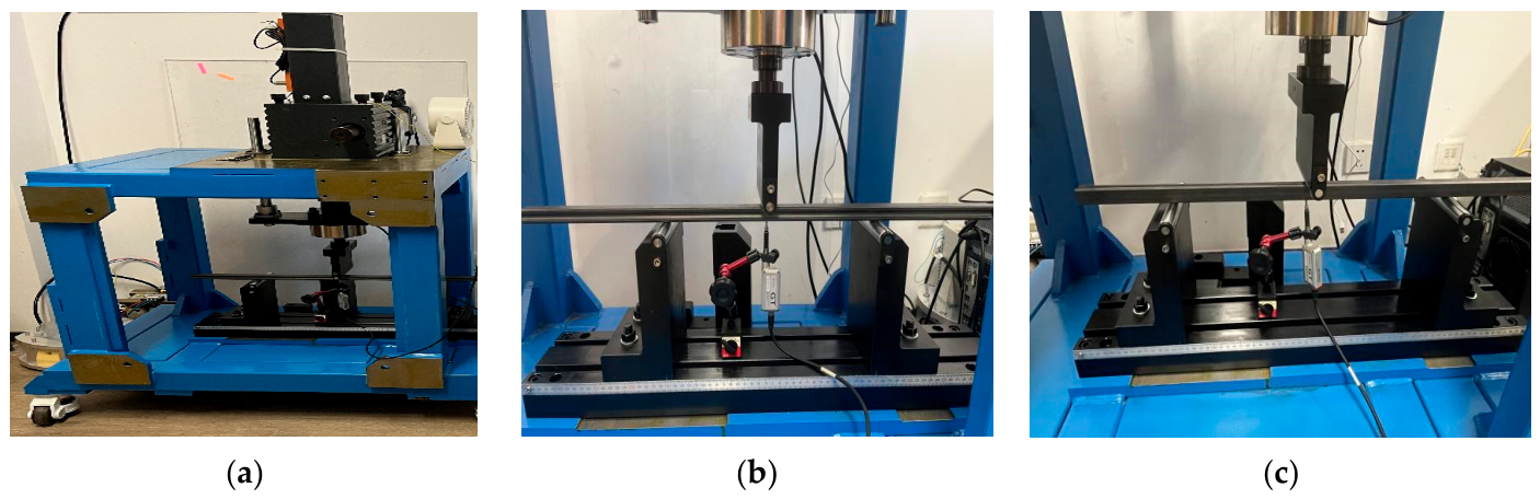
Displacement-controlled three-point bending experiments were conducted to validate the physical accuracy of the layered finite element model and to investigate the mechanical effects of repeated bending on guide rail behavior. The test specimens were 670 mm-long GH20 high-speed linear guide rails, with a uniform straightening and bending span of 400 mm. Macroscopic photographs of the actual GH20 guide rail specimen are shown in Figure 11, illustrating both its overall length and localized cross-sectional profile, to provide a clearer visual impression of the subject under research. All experiments were performed on a custom-designed servo-driven precision straightening platform (Figure 12), which was specifically developed for testing full-scale linear guides. The unloading dwell time was set to 2 s, and residual deflection was continuously monitored and recorded by a contact-type displacement sensor (KEYENCE GT2 series, Keyence Corporation, Osaka, Japan) with a resolution of 1 μm. Building on this platform, single-cycle discrete-stroke loading tests were first performed on specimens with no initial deformation, and the measured residual deflections were compared against the hierarchical finite element simulation results established in Section 2.
Figure 11.
Photographs of the GH20 high-speed linear guide rail specimen: (a) full-length macroscopic overview; (b) localized profile and surface detail.
Figure 12.
Displacement-controlled three-point straightening experimental system: (a) three-point straightening test equipment for guide rails; (b) vertical straightening configuration; (c) lateral straightening configuration.
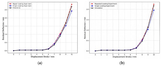
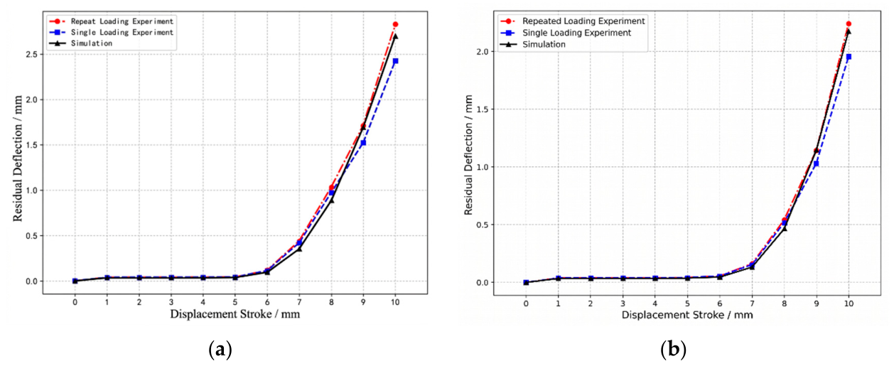
As shown in Figure 13, the single-load experimental curves agree closely with the finite element simulation curves in terms of overall trend, with relative errors remaining within 19% across all conditions and both straightening configurations. This result conclusively demonstrates that the layered finite element model incorporating the hardened layer constructed in this study accurately predicts the bending response of guide rails in a load-history-free state, and that the resulting prediction dataset possesses high physical reliability.
Figure 13.
Comparison of stroke–residual deflection curves: (a) vertical straightening; (b) lateral straightening.
3.2. Repeated-Loading Experiments and Revelation of the Cumulative Plasticity Effect
To address the multi-pass trial correction procedures that are pervasive in actual straightening operations, back-to-back comparative experiments under single-load and repeated-load conditions were conducted to reveal the influence of cumulative plasticity on the bending response of guide rails. As presented in Table 3 and Table 4, under identical straightening strokes S, the residual deflections obtained from repeated-loading experiments were significantly and systematically larger than those from single-load experiments (i.e., the model-predicted values), with the discrepancy widening progressively as the stroke increased. In-depth analysis of the experimental curves reveals that once the guide rail undergoes its first plastic deformation, the combined effect of the induced residual stress field and accumulated plastic strain causes a substantial shift in the mechanical reference state of the hardened-layer guide rail. This “loading history” renders the cross-section exceptionally sensitive to subsequent deformation—springback is markedly reduced and residual deformation is correspondingly increased. This phenomenon confirms the existence of a significant cumulative plasticity effect in guide rails subjected to repeated bending cycles.
Table 3.
Comparison of experimental and simulated residual deflections for vertical straightening at different straightening strokes.
Table 4.
Comparison of experimental and simulated residual deflections for lateral straightening at different straightening strokes.
From a layered mechanics perspective, after the first loading cycle, the highly strain-hardened layer retains a substantial quantity of residual plastic deformation and a complex internal stress field, which fundamentally alter the elastoplastic reference state for all subsequent loading events, causing the cross-section to exhibit elevated plastic sensitivity. This physical finding exposes a critical limitation of purely theoretical prediction methods: since the reverse FEA dataset is constructed under an idealized stress-free state, it can provide reliable predictions only for the initial straightening stroke. If the same prediction data are rigidly applied to guide subsequent correction strokes in a multi-pass process, a gross overestimation of the required stroke will inevitably result, creating a severe risk of over-straightening. It is therefore essential to supplement the simulation-derived initial value with a compensation mechanism driven by measured feedback.
4. Proposal and Application of the Hybrid Straightening Strategy
As established in the preceding sections, although the inverse FEA dataset accurately predicts the bending response of guide rails in a load-history-free state, the cumulative plasticity effect induced by repeated bending fundamentally alters the subsequent mechanical baseline of the rail. Continued reliance on the simulation dataset throughout multi-step correction passes will therefore inevitably result in severe over-straightening. To address this core challenge, a two-stage hybrid straightening strategy combining initial-pass prediction with subsequent constraint-based compensation is proposed and validated through comparative engineering experiments. This strategy aims to resolve the persistent engineering problems of high over-straightening risk and low efficiency by integrating the efficient initial-value prediction capability of the FEA dataset with the precise convergence control afforded by measured experimental feedback.
4.1. Design of the Hybrid Straightening Algorithm
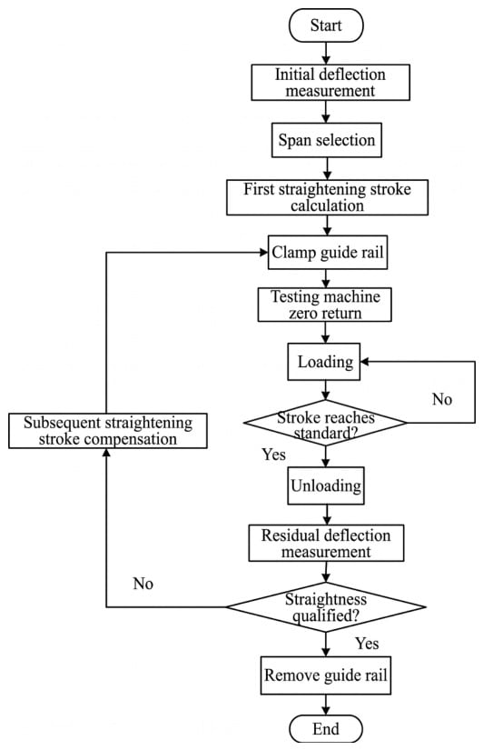
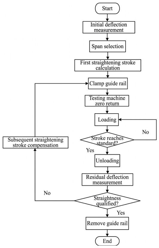
The central concept of this strategy is to decouple the complex straightening process into two physically distinct stages: the theoretical elimination of large deformations and the experimental approximation of small residual errors. The complete process flow is illustrated in Figure 14.
Figure 14.
Process flow for selecting the straightening stroke under the hybrid strategy.
- Initial-Pass Straightening Prediction
The guide rail in its unloaded initial state satisfies the applicability conditions of the FEA dataset. The actual initial deflection of the rail is first measured, and an appropriate straightening span is selected according to the principle of prioritizing efficiency for large deflections and accuracy for small deflections. The three-dimensional prediction dataset constructed in Section 2 is then directly invoked, and the interpolation inversion algorithm (Equation (2)) is used to compute the initial straightening stroke, which is subsequently applied as a quantitative, single-pass loading. The objective of this stage is to exploit the computational efficiency of the simulation initial value to eliminate 85–95% of the initial large deformation in a single pass.
- 2.
- Constraint Compensation Correction
Following unloading after the initial pass, if the absolute value of the residual deflection has not yet met the target tolerance (set at <0.05 mm in this study), the compensation stage is initiated. Since the guide rail has already accumulated plasticity at this point, the simulation dataset is entirely abandoned in this stage. Instead, an iterative correction method is adopted, using the initial-pass stroke S1* as the reference anchor and the measured residual deflection as the feedback signal, governed by the following three principles:
- (a)
- Upper-Bound Constraint Principle: After the initial straightening pass, the residual deflection is typically only 5–15% of the initial deflection, and the required compensation stroke is substantially smaller than the initial stroke. This is because the cumulative plasticity effect renders the guide rail considerably more susceptible to plastic deformation during subsequent loading, markedly elevating the risk of over-straightening under large-stroke loading. Extensive repeated bending tests conducted in the course of this research demonstrate that the plastic sensitivity of the cross-section increases significantly after first yielding; should the compensation stroke exceed 30–35% of the initial stroke, reverse yielding is highly likely to occur. Accordingly, S1*/3 is established as the upper bound for any single compensation stroke.
- (b)
- Deflection Correlation Principle: Within the upper-bound constraint, the compensation stroke should be directly proportional to the magnitude of the current residual deflection. When the residual deflection is relatively large, the compensation stroke may approach the upper bound; when the residual deflection is small, the compensation stroke should be set significantly below the upper bound to minimize the risk of over-straightening.
- (c)
- Monotonically Decreasing Principle: Residual deflection must be re-measured after each compensatory loading pass. If the target tolerance has not been achieved, each subsequent compensation stroke must not exceed the preceding one, ensuring that the residual deflection converges monotonically to within the acceptance range.
4.2. Experimental Comparison and Validation of the Hybrid Straightening Strategy
To comprehensively evaluate the effectiveness of the proposed feedforward-prediction plus closed-loop compensation hybrid strategy under industrial conditions, systematic comparative validation experiments were conducted on a servo-driven precision straightening platform. A head-to-head comparison with the traditional empirical trial-and-error method commonly employed in industrial settings was performed, with particular focus on convergence efficiency, accuracy consistency, and the ability to suppress the over-straightening risk induced by cumulative plasticity when processing guide rails with hardened layers.
4.2.1. Experimental Protocol and Sample Deflection Gradient Design
GH20 high-speed linear guides were selected as test subjects, with a uniform support span of 400 mm. To cover the full range of typical deformation magnitudes encountered in production, three groups of comparative specimens were prepared based on initial deflection gradients, with target values of 0.5 mm, 1.5 mm, and 3.0 mm representing low, medium, and high deformation levels, respectively. For each of the two straightening configurations (vertical and lateral), three sample groups were established, each comprising two guide rails: one straightened using the proposed hybrid strategy and one straightened using the traditional empirical method. The acceptance criterion for all specimens was uniformly set as an absolute residual deflection below 0.05 mm. Following specimen preparation, the actual initial deflection of each guide rail was measured individually using a feeler gauge on a deflection measurement reference surface. The measurement results are presented in Table 5 and were used as the basis for span selection and stroke calculation in all subsequent procedures.
Table 5.
Measured initial deflections of the guide rail specimens.
4.2.2. Straightening Experiments Based on the Hybrid Straightening Strategy
The straightening span and initial straightening stroke for each specimen were computed using the span selection and stroke selection methods described above. The calculation procedure for the initial-pass stroke is illustrated using Vertical A1 as an example: the measured initial deflection is 0.574 mm, and the span selected according to the span selection criterion is 300 mm. Within the prediction dataset for a span of 300 mm, the two bounding data points nearest to 0.574 mm are (Slower = 5.0 mm, δlower = 0.551 mm) and (Supper = 5.1 mm, δupper = 0.628 mm). Substituting these values into Equation (2) yields a predicted straightening stroke of approximately 5.030 mm. The calculated initial strokes for all other specimens are summarized in Table 6.
Table 6.
Predicted straightening strokes for all specimens.
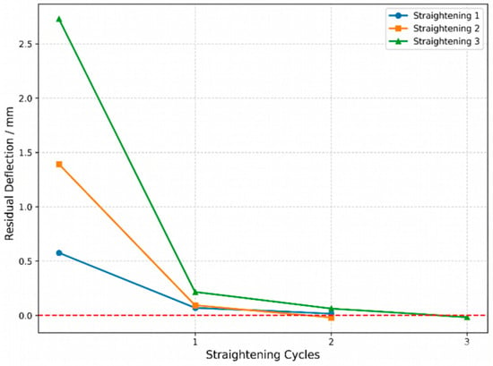
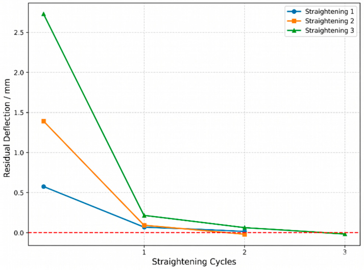
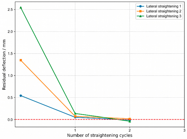
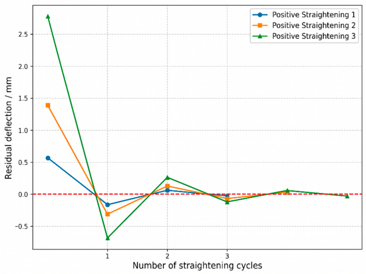
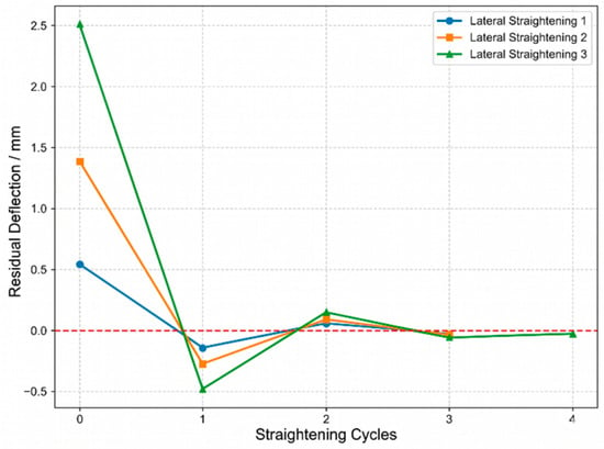
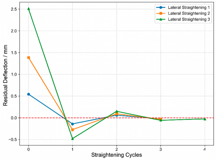
The initial straightening strokes were determined by interpolation inversion of the prediction dataset. Stroke selection for subsequent compensation passes followed the three principles outlined in Section 4.1. Taking Vertical A1 as a representative example: upon unloading after the initial pass, the measured residual deflection was 0.068 mm, which did not yet satisfy the acceptance criterion. The upper bound of the compensation stroke is 1.677 mm (=S1*/3 = 5.030/3). Given that the current residual deflection is small and close to the acceptance threshold, the compensation stroke was set to 1.200 mm (approximately 23.9% of S1*), satisfying both the upper-bound constraint and the deflection correlation principle. The complete straightening process records for the vertical and lateral configurations are presented in Table 7 and Table 8, respectively. Residual deflection convergence curves derived from these data are plotted in Figure 15 and Figure 16.
Table 7.
Experimental data for vertical straightening using the hybrid strategy.
Table 8.
Experimental data for lateral straightening using the hybrid strategy.
Figure 15.
Residual deflection convergence curves for vertical straightening using the hybrid strategy. The red dashed line represents the ideal zero residual deflection.
Figure 16.
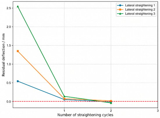
Residual deflection convergence curves for lateral straightening using the hybrid strategy. The red dashed line represents the ideal zero residual deflection.
4.2.3. Straightening Experiments Based on the Traditional Empirical Method
In the comparative experiments employing the traditional empirical method, the same support spans were used; the sole difference lay in how the straightening stroke was determined. For each loading pass, the operator selected the stroke length empirically based on the currently measured residual deflection, and the load-measuring cycle was repeated until the guide rail met the acceptance criterion. The straightening process records for the vertical and lateral configurations are presented in Table 9 and Table 10, with the corresponding residual deflection convergence curves shown in Figure 17 and Figure 18.
Table 9.
Experimental data for vertical straightening using the traditional empirical method.
Table 10.
Experimental data for lateral straightening using the traditional empirical method.
Figure 17.
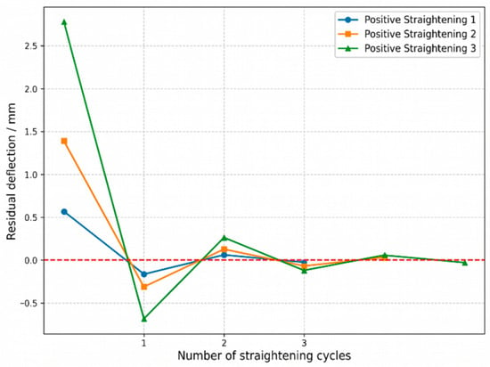
Residual deflection convergence curves for vertical straightening using the traditional empirical method. The red dashed line represents the ideal zero residual deflection.
Figure 18.
Residual deflection convergence curves for lateral straightening using the traditional empirical method. The red dashed line represents the ideal zero residual deflection.
The experimental results confirm that the traditional empirical method is capable of progressively reducing residual deflection and ultimately bringing all specimens into compliance under both straightening configurations. However, this method exhibits a pronounced trial-and-error character: the majority of specimens experience a degree of over-straightening immediately after the first loading pass, necessitating multiple subsequent reverse corrections to converge toward the target range. Overall, while the traditional method satisfies the straightening requirements, its convergence process is comparatively oscillatory and the number of passes required to achieve the target straightness is substantially higher.
4.3. Comparative Analysis of the Hybrid Strategy and the Traditional Empirical Method
As shown in Figure 15 and Figure 16, the hybrid strategy proposed in this study demonstrates outstanding convergence performance. During the initial-pass stage, the dataset-predicted stroke eliminates 85–95% of the initial deformation in a single loading. In the ensuing compensation stage, the strict upper-bound constraint principle enforces monotone, smooth convergence of the residual deflection, enabling all specimens to achieve high-precision compliance within two to three passes and effectively preventing out-of-tolerance over-straightening, restricting any minor sign reversal strictly within the ±0.05 mm target threshold.
In marked contrast, as illustrated in Figure 17 and Figure 18, the traditional empirical method exhibits strongly pronounced trial-and-error and oscillatory behavior. In the absence of a theoretically grounded initial value and without cumulative plasticity constraints, most specimens undergo positive-to-negative deflection reversal (over-straightening) immediately after the first loading pass, necessitating reverse corrective bending. This oscillatory behavior substantially increases the number of passes required to reach compliance—in some cases exceeding four to five—severely impeding processing efficiency and elevating the risk of material fatigue.
The physical root cause of the severe positive-to-negative deflection reversal observed with the traditional empirical method lies in the fact that manual trial estimates are essentially proportional extrapolations based on linear intuition. The extremely high hardening coefficient of the martensitic hardened layer, however, imparts strong nonlinearity to the bending response of the guide rail, and cumulative plasticity further amplifies this nonlinearity. Human operators are unable to intuitively and accurately anticipate the abrupt transition boundaries of this nonlinearity, making over-straightening virtually unavoidable. The strategy proposed in this study, by contrast, employs inverse FEA to establish a global map of the nonlinear behavior and supplements it with strict closed-loop truncation constraints, mechanically precluding the pathway to over-straightening. Although the sample size in the current comparative experiments is relatively limited due to the high cost and labor intensity of preparing full-scale industrial guide rail specimens, the deterministic and non-oscillatory convergence behavior consistently observed across all tested deformation levels strongly validates the engineering feasibility of the proposed approach. Comprehensive comparative results confirm that the proposed reference prediction plus feedback constraint hybrid strategy successfully bridges the gap between pure theoretical simulation and the complex physical state of actual machining, achieving substantial improvements in straightening efficiency, first-pass yield, and process safety, and demonstrating significant industrial application value.
5. Conclusions
This paper addresses the challenges of nonlinear springback and cumulative plasticity inherent in the three-point straightening process of high-speed linear guide rails with induction-hardened layers, and proposes a two-stage hybrid straightening strategy based on inverse finite element modeling and experimental feedback. Through mechanistic analysis, simulation-based prediction, and systematic experimental validation, the following principal conclusions are drawn:
- The differential influence mechanism of the hardened layer on the straightening response was elucidated. The constitutive characteristics of the hardened layer—exceptionally high yield strength and high strain hardening coefficient—produce fundamentally different elastoplastic intervention mechanisms under vertical and lateral straightening conditions. During large-stroke vertical straightening, attainment of the hardened layer’s tensile strength limit readily triggers a step-like discontinuous increase in residual deflection. Lateral straightening, in contrast, exhibits a smooth, progressive yielding characteristic with synchronous advancement of the plastic zone across the entire cross-section. These findings establish that the conventional assumption of homogeneous material is no longer valid for guide rails with hardened layers, and that a layered finite element model must be employed for their independent evaluation.
- An efficient, high-precision baseline prediction dataset was constructed. The proposed inverse simulation strategy effectively circumvents the computational bottleneck associated with the exhaustive enumeration of stochastic initial deflection conditions in industrial production, yielding a comprehensive three-dimensional response prediction dataset relating span, stroke, and residual deflection. The interpolation inversion algorithm built on this dataset furnishes highly reliable quantitative initial values for the initial straightening pass, enabling 85–95% of the initial large deformation to be eliminated in a single loading cycle.
- Experiments confirmed the detrimental nature of cumulative plasticity under repeated straightening. Back-to-back repeated-loading experiments clearly established that guide rails exhibit significant cumulative plasticity after multiple bending and unloading cycles. Residual stresses and plastic strain accumulation induced by prior loading substantially elevate the plastic sensitivity of the cross-section, demonstrating conclusively that exclusive reliance on simulation-predicted initial values in actual multi-pass correction processes will inevitably result in severe over-straightening.
- The engineering superiority of the hybrid straightening strategy was verified. The proposed two-stage approach—combining initial-pass prediction with subsequent constraint-based compensation—by introducing an upper-bound constraint principle and a sequentially decreasing compensation scheme driven by measured feedback, successfully bridges the gap between pure theoretical simulation and complex physical machining reality. Comparative experiments demonstrate that this strategy effectively suppresses the severe positive-to-negative deflection reversal characteristic of the traditional empirical trial-and-error method. All specimens consistently achieve the high-precision target of an absolute residual deflection below 0.05 mm within two to three loading cycles, significantly enhancing both straightening efficiency and process safety.
Author Contributions
Conceptualization, Y.H. and C.Y.; methodology, Y.H. and Y.Z.; software, Y.H.; validation, Y.H., Y.Z. and C.Y.; formal analysis, Y.H.; investigation, Y.H.; resources, C.Y. and Y.Z.; data curation, Y.H.; writing—original draft preparation, Y.H.; writing—review and editing, C.Y. and Y.Z.; visualization, Y.H.; supervision, C.Y.; project administration, C.Y.; funding acquisition, C.Y. and Y.Z. All authors have read and agreed to the published version of the manuscript.
Funding
This research was funded by: Zhejiang Provincial Natural Science Joint Fund Key Project, grant number LLSSZ24E050001; Key R&D Program of Lishui City, grant number 2023ZDYF01.
Data Availability Statement
The original contributions presented in this study are included in the article. Further inquiries can be directed to the corresponding author.
Conflicts of Interest
The authors declare no conflicts of interest.
References
- Li, D.; Liu, X.; Li, L.; Guo, G. Influence of geometric parameters of rolling linear guides on lubrication performance considering the effect of stiffness. J. Mech. Eng. 2021, 57, 100–108. [Google Scholar] [CrossRef] [Scilit]
- Tong, V.; Khim, G.; Hong, S.; Park, C.-H. Construction and validation of a theoretical model of the stiffness matrix of a linear ball guide with consideration of carriage flexibility. Mech. Mach. Theory 2019, 140, 123–143. [Google Scholar] [CrossRef] [Scilit]
- Lu, H.; Zhang, Y.; Gao, S.; Ling, H. Study on a straightening stroke prediction model considering stress superposition. J. Huazhong Univ. Sci. Technol. Nat. Sci. 2016, 44, 65–70. [Google Scholar] [CrossRef]
- Li, X.; Jiang, C.; Zhang, M.; Zhang, W.; Sun, L. Development of induction heat treatment technologies and equipment for key components of machine tools. Heat Treat. Met. 2025, 50, 308–317. [Google Scholar]
- Yu, M.; Liu, X. Surface hardening process for 40Cr13 guideways. Met. Process. 2013, 7, 41. [Google Scholar]
- Li, H.; Gao, Z. Study on high-frequency surface hardening of machine bed guideways. Mech. Res. Appl. 2000, 13, 43–45. [Google Scholar]
- Rathinasuriyan, C.; Karthik, K.; Udhayaraj, S.; Bishwakarma, S. Investigation of induction hardening on heat-treated EN8 steel by alternately timed quenching process. Mater Today Proc. 2003; in press. [CrossRef] [Scilit]
- Lü, Y. Advanced and practical heat treatment technologies and equipment for rolling linear guides. Met. Process 2019, S2, 252–255. [Google Scholar]
- Slatter, T.; Lewis, R.; Jones, A.H. The influence of induction hardening on the impact wear resistance of compacted graphite iron (CGI). Wear 2011, 270, 302–311. [Google Scholar] [CrossRef] [Scilit]
- Kristoffersen, H.; Vomacka, P. Influence of process parameters for induction hardening on residual stresses. Mater. Des. 2001, 22, 637–644. [Google Scholar] [CrossRef] [Scilit]
- Guan, B.; Zang, Y.; Qu, W. Current status and prospects of research on straightening theory. Mech. Des. Manuf. 2012, 266–268. [Google Scholar]
- Cao, A.; Xiong, G. Development of pressure straightening technology. Forg. Press Equip. Manuf. Technol. 2007, 42, 9–12. [Google Scholar]
- Li, J.; Zou, H.; Xiong, G. Current status and prospects of theoretical research on pressure straightening processes. Mach. Des. Res. 2004, 20, 69–71. [Google Scholar]
- Zhang, Y.; Lu, H.; Ling, H.; Lian, Y.; Ma, M. Analytical model of a multi-step straightening process for linear guideways considering neutral axis deviation. Symmetry 2018, 10, 316. [Google Scholar] [CrossRef] [Scilit]
- Ma, Z.; Ma, L.; Huang, Q.; Ma, L.; Chu, Z.; Huang, Z. A two-roll straightening springback model for bars based on elasto-plastic pressure neutral axis deviation. J. Cent. South Univ. Nat. Sci. 2016, 47, 3020–3030. [Google Scholar]
- Zhang, C.; Zang, Y.; Guan, B.; Qin, Q. Analytical study of the roll straightening process of bimetallic composite plates based on curvature integrals. J. Zhejiang Univ. Eng. Sci. 2017, 51, 1575–1586. [Google Scholar]
- Song, D.; Zhang, Y.; Du, J.; Yi, X.; Sun, Y.; Cui, Y. Deformation analysis and parameter optimization of strip tension-bending straightening. J. Plast. Eng. 2021, 28, 84–90. [Google Scholar]
- Zhai, H.; Wu, Y.; Liu, X.; Li, Q.; Wang, Y. Variations of stress and deformation in the straightening process of turnout base plate. J. Mech. Sci. Technol. 2022, 36, 3353–3360. [Google Scholar] [CrossRef] [Scilit]
- Liu, L.; Zhou, C.; Cheng, J.; Ma, X.; Chen, Z. Experimental study on the elasto-plastic bending behavior during aluminum sheet straightening. Heavy Mach. 2020, 25–30. [Google Scholar]
- Shinkin, V.N. Simplified calculation of the bending torques of steel sheet and the roller reaction in a straightening machine. Steel Transl. 2017, 47, 639–644. [Google Scholar] [CrossRef] [Scilit]
- Hassan, M.; Ali, A.; Ilyas, M.; Hussain, G.; Haq, I.U. Experimental and numerical simulation of steel/steel (St/St) interface in bi-layer sheet metal. Int. J. Lightweight Mater. Manuf. 2019, 2, 89–96. [Google Scholar] [CrossRef] [Scilit]
- Zhou, K.; Zhang, X.; Liu, R.; Sun, X.; Tang, D.; Li, D.; Wang, H. Mechanical responses and deformation mechanisms in the AZ31 magnesium alloy during cyclic bending. Int. J. Mech. Sci. 2024, 275, 109314. [Google Scholar] [CrossRef] [Scilit]
- Hao, Z.; Luo, J.; Chen, L.; Cai, Y.; Chen, Y.; Cheng, M. Failure mechanism of unequal parameters metal bellows under repeated bending process. Eng. Fail. Anal. 2021, 129, 105671. [Google Scholar] [CrossRef] [Scilit]
- He, J.; Cu, S.; Xia, H.; Sun, Y.; Xiao, W.; Ren, Y. High accuracy roll forming springback prediction model of SVR based on SA-PSO optimization. J. Intell. Manuf. 2025, 36, 167–183. [Google Scholar] [CrossRef] [Scilit]
- Yang, B.; Zeng, Y.; Yang, H.; Oscoz, M.P.; Ortiz, M. Springback prediction using point series and deep learning. Int. J. Adv. Manuf. Technol. 2024, 132, 4723–4735. [Google Scholar] [CrossRef] [Scilit]
- Wang, H.; Lim, H.; Yoon, J.W. Stress-aware graph neural network for springback prediction considering material variations. J. Mater. Process. Technol. 2025, 348, 119189. [Google Scholar] [CrossRef] [Scilit]
- He, X.; Ma, J.; Welo, T. Real-time and data-efficient springback prediction in tube bending using force measurement and physics-informed machine learning. J. Manuf. Process. 2025, 156, 645–660. [Google Scholar] [CrossRef] [Scilit]
- Hong, M.; Zhang, W. Springback prediction of free bending based on experimental method. Appl. Sci. 2023, 13, 8288. [Google Scholar] [CrossRef] [Scilit]
- ISO 14728:2017; Rolling Bearings—Linear Motion Rolling Bearings. ISO: Geneva, Switzerland, 2017.
- ISO 18203:2016; Steel—Determination of the Thickness of Surface-Hardened Layers. ISO: Geneva, Switzerland, 2016.


Disclaimer/Publisher’s Note: The statements, opinions and data contained in all publications are solely those of the individual author(s) and contributor(s) and not of MDPI and/or the editor(s). MDPI and/or the editor(s) disclaim responsibility for any injury to people or property resulting from any ideas, methods, instructions or products referred to in the content. |
© 2026 by the authors. Licensee MDPI, Basel, Switzerland. This article is an open access article distributed under the terms and conditions of the Creative Commons Attribution (CC BY) license.