


Abstract
The structural safety of a marine remotely operated vehicle (ROV) launch and recovery system (LARS) under extreme sea conditions determines the reliability of underwater exploration. To address the susceptibility of traditional rigid frames to local yielding and dynamic instability under transient high-frequency impacts from a mother ship, this study conducts structural dynamics simulation and vibration reduction optimization for a heavy-duty ROV LARS. A spatial finite element model was established, introducing boundary conditions that decouple the static gravity field from the transient inertial mass. Mechanical responses under eight typical operating conditions were systematically evaluated. Results indicate that the rigid frame experiences significant limitations under a 1 g horizontal transient impact, with peak stress reaching 195.38 MPa and deformation exceeding 20 mm. Consequently, a non-invasive vibration reduction strategy using viscoelastic damping boundaries is proposed, alongside an equivalent buffer dynamics model. Verifications demonstrate that this flexible damping constraint prolongs collision momentum transfer time and dissipates impact kinetic energy. Post-optimization, maximum transverse and longitudinal von Mises stresses decrease by over 37%, and transient deformation is reduced by over 64%. This study addresses the weight penalty of traditional strengthening designs, providing a mechanical reference for the lightweight design and impact protection of heavy-duty marine equipment.
1. Introduction
With the continuous advancement of global marine resource development strategies, the concepts of ‘intelligent, green, deep-sea, and polar’ have become the core dimensions in the technological development of marine equipment. Meanwhile, subsea exploration and underwater operation technologies have become core indicators for measuring the autonomous manufacturing capabilities and strategic competitiveness of modern marine engineering equipment. As the core carrier for executing complex tasks such as seabed exploration, underwater pipeline network maintenance, and target salvage, the remotely operated vehicle (ROV) plays an irreplaceable role in modern marine engineering [1]. As underwater equipment expands towards large-scale, subsea, and multi-functional directions, stricter demands are placed on the lightweight design of support structures and the extreme mechanical properties of materials. Serving as the mechanical hub connecting the surface mother ship and the underwater payload, the structural integrity and dynamic stability of the launch and recovery system directly define the physical safety baseline and operational boundaries of the entire exploration mission [2]. However, in complex and variable pelagic environments, mother ships are subjected to strong coupling excitations from wind, waves, and currents, generating severe six-degree-of-freedom high-frequency sway and transient heave motions [3,4]. These violently fluctuating environmental loads interact with rigid frames and flexible cable systems through complex nonlinear coupling, which is highly prone to inducing high stress concentrations, fatigue damage, and even transient instability responses along the main force transmission paths of the launch and recovery system. In actual marine engineering hoisting operations, the ship heave and sway motions caused by waves not only reduce the positioning accuracy of recovery operations, but also cause destructive alternating tension and slack effects in the winch system, further inducing transient high-frequency impact loads capable of threatening structural survival [5,6]. Furthermore, the dynamic evolution characteristics of transient impacts under extreme sea conditions exhibit a high degree of abruptness and unpredictability, further amplifying the mechanical response risks of the floating body system [7,8]. Therefore, conducting in-depth research on the multi-body dynamic response laws and structural anti-impact performance of marine heavy-duty launch and recovery systems under extreme transient impacts is not only an urgent engineering requirement to enhance the reliability of marine equipment, but also an inevitable choice to perfect the dynamic design theory of complex equipment in extreme marine environments.
In recent years, extensive research has been conducted by the international academic community on the structural strength and dynamic response issues of special marine engineering operation equipment and large spatial load-bearing frames. In the field of high-fidelity finite element simulation for large frame structures, Liu et al. [9] confirmed that multiphysics coupling analysis and high-order mesh discretization techniques can effectively improve the evaluation accuracy of structural stress fields under complex loads. For core equipment such as subsea pressure hulls and floating production storage and offloading (FPSO) units, Romero-Tello et al. [10] and Qiu et al. [11] conducted systematic structural strength evaluations and lightweight size optimization designs, providing essential guarantees for enhancing the environmental adaptability of the equipment. Furthermore, Berardi et al. [12] and Guan et al. [13] applied high-order solid elements to the finite element discretization of the connection frames of lifting platforms and wheeled cranes, accurately capturing the stress concentration and fatigue damage evolution characteristics in geometric mutation zones. In response to extreme marine environmental loads, Ma et al. [14] deeply analyzed the transient response mechanisms and safety protection strategies of structures subjected to ship collisions or wave slamming conditions.
Beyond the field of marine engineering, finite element analysis and topology optimization of spatial rigid frame structures have also been fully developed in other transport and load-bearing equipment, yet traditional structural hardening strategies have exposed obvious mechanical limitations. Yang et al. [15] and Lonkwic et al. [16] pointed out in their structural optimization studies that pure structural hardening not only leads to a sharp increase in system dead weight, but also easily triggers a nonlinear extension of manufacturing time. Aiming at the size and shape optimization of complex load-bearing structures, Lopez et al. [17] proposed a parameter calibration method combining analytical and numerical discretization synergy. Ghannadi et al. [18] and Wang et al. [19] explored the structural multi-objective collaborative optimization and finite element forming limit characterization under different dynamic load excitations, revealing the mechanical boundaries of material strengthening. Regarding various load-bearing vehicles and pipeline frames, the studies by Zeng et al. [20] and Batista et al. [21] indicated that frequency domain analysis and precise positioning of resonance source transmission paths provided core numerical references for the anti-fatigue design of structures. Additionally, Bagha and Bahl [22] and Huang et al. [23] confirmed that under complex environmental stresses and diverse load distributions, traditional full-frame hardening strategies could not effectively prevent high-frequency impact damage to components.
In this context, introducing non-invasive viscoelastic damping mechanisms into the anti-impact design of heavy-duty equipment has gradually become a prominent development direction for structural dynamics optimization. Xu et al. [24] and Zheng et al. [25] adopted fractional derivative methods and internal variable theory to mathematically model viscoelastic dampers, high-precisely characterizing the stiffness and viscosity coefficients of complex damping bodies under broadband excitations. Xu et al. [26] and Kasai et al. [27] deeply investigated three-chain micromolecular configurations and tube constraint effects, revealing the energy dissipation and work principles of viscoelastic materials under different environments and heat transfer effects. Comprehensive validation studies on passive dampers by Takewaki [28] and Wu et al. [29] confirmed their reliability in suppressing transient vibrations under extreme nonlinear loading. Hosseini et al. [30] and Yang et al. [31] integrated equivalent dampers into the critical stress nodes of spatial reticulated shells and large building structures, reflecting the significant engineering advantages of flexible dynamic energy dissipation boundaries in reducing high-frequency acceleration excitation peaks and controlling transient large deformations. Furthermore, the wave heave compensation analyses of marine winch systems and underwater ROVs by Xie et al. [32] and Yu et al. [33] demonstrated that introducing dynamic dissipative constraint mechanisms could substantially suppress abrupt variations in cable tension and effectively avoid severe collisions during the equipment’s water entry and exit phases.
Further expanding on the transient dynamic behavior of marine equipment, Deng et al. [3] developed a numerical model to predict wire tension spikes, known as snap loads, during the launch and recovery of a work-class ROV passing through the wave zone. In the context of large spatial rigid frame analysis, Zhang et al. [34] utilized the lumped mass method to systematically investigate the dynamic responses and line tension characteristics of a rigid truss structure under various operational conditions. Through a comprehensive review of the aforementioned research, a distinct viewpoint for this study is formed: relying solely on traditional structural hardening strategies to resist high-frequency transient impacts inevitably exposes obvious weight penalty limitations. Existing works predominantly focus on structural response analysis under quasi-static gravity loads or low-frequency wave excitations. Regarding the high-frequency transient acceleration impacts endured by marine launch and recovery systems under extreme sea conditions, systematic research on the associated dynamic mechanisms and structural response laws remains insufficient. Particularly during actual operations, structures are simultaneously subjected to static gravity and transient inertial forces. Significant differences exist between the two in terms of physical essence and action mechanisms, whereas existing models mostly adopt a unified mass processing approach, which struggles to accurately reflect dynamic responses under authentic working conditions, potentially leading to the failure of anti-collision designs. Moreover, for large-scale spatial frame structures, how to introduce effective vibration reduction and energy dissipation mechanisms to achieve an optimal enhancement of anti-impact performance while ensuring computational efficiency requires further investigation and engineering validation.
To address the aforementioned issues, this paper takes a novel marine ROV launch and recovery system as the research object, constructs a high-fidelity spatial discretized finite element model, and proposes a dynamic modeling framework that decouples the static gravity field from inertial mass effects, reconstructing the description of structural dynamic responses from the perspective of load origins. This method breaks through the physical limitations of traditional unified mass characterization in high-frequency transient analyses, achieving high-precision depictions of impact-driven response processes. On this basis, a non-invasive energy dissipation regulation mechanism based on viscoelastic damping boundaries is introduced, expanding the structural anti-impact design from a “stiffness-dominated” approach to an “energy-regulation” strategy. Through multi-condition coupling analysis, the modulation laws of flexible energy dissipation boundaries on impact momentum transmission paths and response characteristics are systematically revealed.
The main contributions of this paper are as follows: (1) A dynamic modeling method that decouples static gravity from inertial mass effects is proposed, improving the physical accuracy of transient impact analysis; (2) A non-invasive vibration reduction optimization strategy based on viscoelastic damping boundaries is constructed to achieve the effective dissipation of impact kinetic energy; (3) A unified multi-condition analysis framework is established to systematically evaluate the structural dynamic response characteristics of marine ROV launch and recovery systems under extreme load conditions.
2. Model Construction and Simulation Methodology
2.1. Geometric Model of the Launch and Recovery System
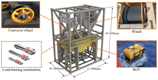
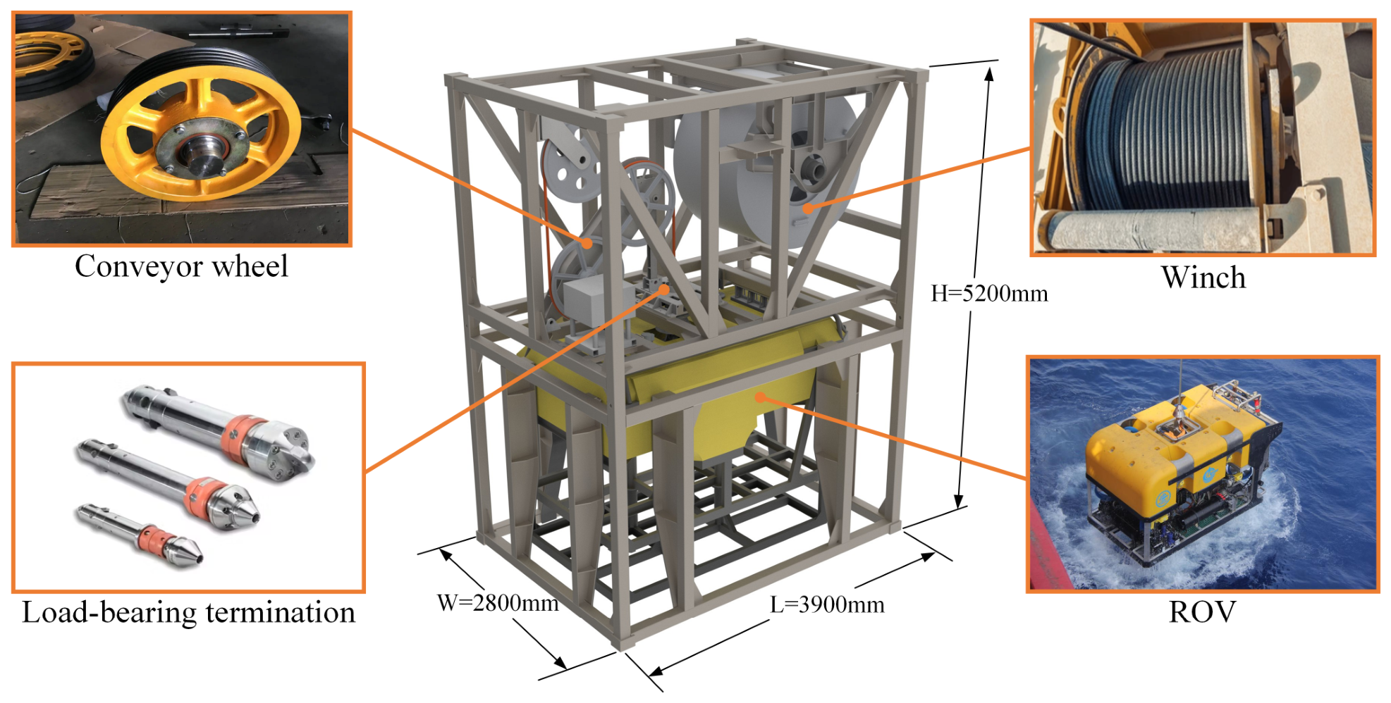
The marine ROV launch and recovery system (LARS) serves as the core hub equipment ensuring the safe deployment and recovery of the underwater exploration system under complex pelagic conditions. The LARS investigated in this study adopts a high-stiffness modular spatial rigid frame structural system, with overall macroscopic dimensions of 3900 mm in length, 2800 mm in width, and 5200 mm in height, as shown in Figure 1.The LARS was manufactured by Hangzhou Navigation Instrument Co., Ltd., Hangzhou, China. Its main load-bearing architecture is assembled by bolting an upper frame and a lower frame together via a high-strength bolt array, a configuration that maintains global rigidity while facilitating modular assembly.
Figure 1.
3D geometric model of the ROV LARS.
The upper frame integrates the power take-up unit, directional guide wheels, and the load-bearing head locking mechanism. These components constitute the load transmission and power input center of the entire system, directly bearing the alternating cable tension and dynamic payload interactions during lifting operations. The lower frame features a hollow interior, with guide rails and anti-collision structures arranged around its perimeter to provide physical limits and directional support for the ROV body. This design effectively restrains wave-induced pendulum motions and lateral impacts, particularly during the critical air-water interface crossing phase.
Before importing the 3D solid model into the finite element analysis (FEA) environment, to suppress the stiffness matrix singularity during the calculation process and improve the convergence efficiency of nonlinear solutions, feature-based geometric simplification and topological cleaning were performed on the original 3D solid model. Based on Saint-Venant’s principle, redundant features that exert no significant impact on the macroscopic stress field distribution—including non-load-bearing process chamfers, tiny assembly holes with diameters less than 5 mm, welding transition fillets, and non-structural fasteners—were systematically eliminated. This procedure avoided the generation of sliver elements or distorted meshes in local geometric mutation zones, thereby optimizing the generation quality of the subsequent mesh under the premise of ensuring the physical and mechanical equivalence of the model.
2.2. Material Properties and Mesh Discretization
The LARS operates in an extreme marine environment for extended periods; thus, the tensile yield strength and corrosion resistance of the materials act as core constraints defining the structural service life. The main load-bearing spatial steel frame of the system includes core components such as the winch main shaft and the main longitudinal beams, all of which are made of TA2 titanium alloy, known for its excellent seawater corrosion resistance. Local connection flanges and auxiliary load-bearing components are manufactured from 316L austenitic stainless steel. Given that the main load-bearing frame and critical stress components of this LARS are constructed from TA2 titanium alloy, while 316L stainless steel is primarily used for non-load-bearing fasteners or auxiliary connectors, the yield strength of TA2 emerges as the critical bottleneck determining the structural safety of the entire unmanned system. To ensure the conservatism and consistency of the verification results, the subsequent analyses in this study uniformly adopt the material properties of TA2 as the failure criterion for the structure. Within the numerical calculation framework, structural materials are characterized using an isotropic linear elastic constitutive model. The constitutive relationship of the material adheres to the generalized Hooke’s law, and its three-dimensional stress and strain states are linearly mapped and matrix-characterized through the elastic modulus and Poisson’s ratio. The core mechanical properties and physical parameters utilized in the numerical simulation are detailed in Table 1.
Table 1.
Key physical and mechanical properties of the ROV LARS materials.
The discretization of the finite element mesh employs ten-node quadratic tetrahedral isoparametric solid elements (C3D10). These high-order elements possess quadratic displacement interpolation functions, which can effectively overcome the shear locking phenomenon that easily occurs in first-order elements during bending-dominated problems, demonstrating excellent geometric adaptability to complex, high-curvature boundaries. Considering the massive overall scale of the LARS and its intricate local assembly features, an independent spatial discretization strategy was adopted for the upper and lower frames. This approach balances the computational economy of large-scale matrix solving with the morphological quality of the mesh, thereby avoiding mesh distortion at complex contact interfaces.
Addressing the complex stress gradient characteristics within the structural domain, the model implements a hierarchical adaptive mesh refinement strategy based on local geometric features and load paths. The global base mesh size was set to 20 mm. This setting effectively controls the scale of degrees of freedom while ensuring macroscopic bending stiffness and the overall dynamic response accuracy of the structure, thus balancing computational precision and solving efficiency. The finite element discretization error is closely related to the characteristic element size and the structural characteristic scale, and its error level can be expressed as:
where is the characteristic size of the element, is the characteristic length of the structure, and is the interpolation order of the element. For the quadratic tetrahedral elements adopted in this paper, = 2. The overall dimensions of the LARS are 3900 mm in length, 2800 mm in width, and 5200 mm in height, with the characteristic scales of the main load-bearing components ranging from 1000 mm to 4000 mm. Under these conditions, selecting 20 mm as the global mesh size corresponds to a scale ratio / of approximately 1/50 to 1/200, which satisfies the computational accuracy requirements for overall stiffness and displacement responses. Minor perturbations around this scale only cause slight variations in the scale ratio, and their impact on the discretization error remains within the same order of magnitude; therefore, no further distinction is made.
Based on the global mesh, a hierarchical refinement strategy is introduced to enhance the stress resolution capabilities in critical regions. For main force transmission path areas, such as the middle bracket of the upper frame, the mesh size was refined to 10 mm; for geometric mutation areas, including the interface between the upper and lower frames, the bellmouth support base, and the flange transition fillets, it was further refined to 5 mm. This hierarchical scale is not selected arbitrarily but is jointly determined by the finite element error convergence characteristics and stress gradient distribution features. For quadratic elements, the error converges quadratically with mesh size; that is, when the element size is halved, the theoretical error can be reduced to approximately one-quarter of its original value. Therefore, adopting a progressive relationship of 20 mm, 10 mm, and 5 mm can achieve a stepwise attenuation of errors with limited computational costs, improve the calculation accuracy in critical areas, and simultaneously prevent numerical instability caused by irregular scale divisions.
Furthermore, local mesh refinement adheres to the principle of stress gradient control, meaning that the element size must be smaller than the characteristic scale of stress variation. This constraint relationship can be expressed as:
where is the magnitude of the stress gradient. When geometric mutations or load path turning points exist in the structure, the stress gradient increases significantly, necessitating a reduction in element size to guarantee the continuity and accuracy of stress field interpolation. The 10 mm and 5 mm mesh sizes can effectively cover the gradient variation range of main force transmission paths and stress concentration zones, thereby averting local stress underestimation or numerical oscillation phenomena.
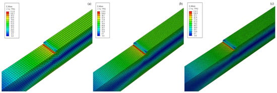
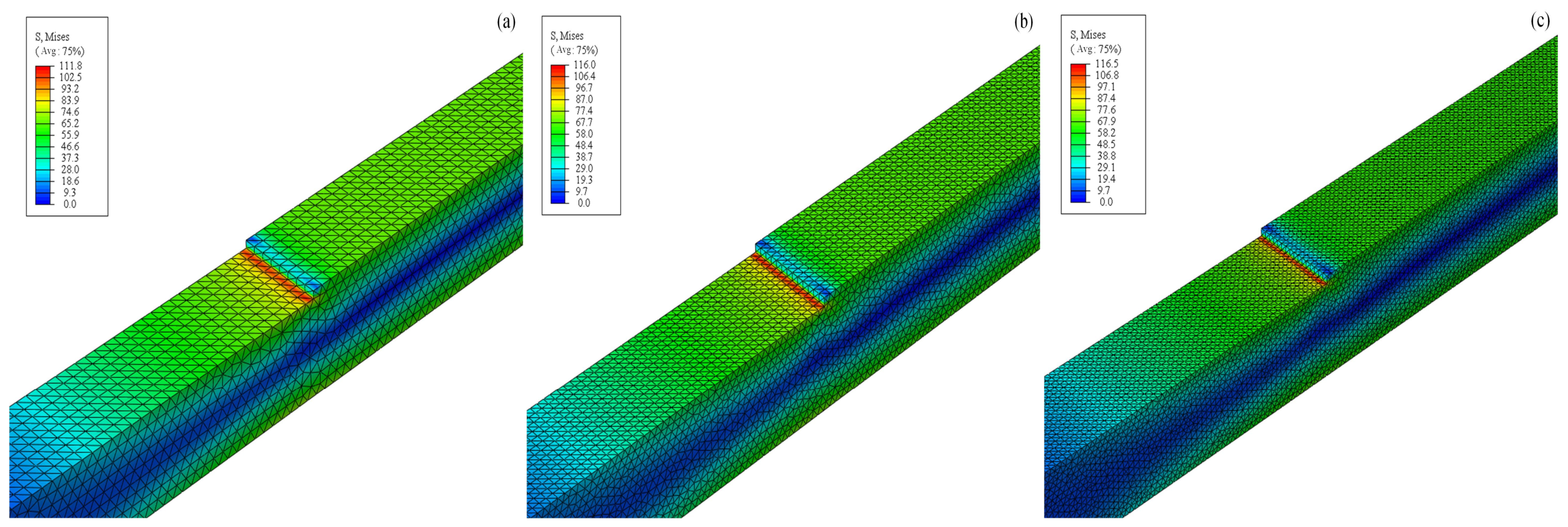
To ensure the numerical reliability of the subsequent dynamic analyses and eliminate the influence of grid size on the structural stiffness matrix, a mesh convergence study was conducted prior to modal extraction. The verification targeted the high-stress concentration area at the middle bearing beam of the upper frame under the static storage condition. As shown in Figure 2, when the local mesh size was progressively refined to 15 mm, 10 mm, and 8 mm, the resulting peak von Mises stresses were 111.8 MPa, 116.0 MPa, and 116.5 MPa, respectively. Because the relative variation in peak stress dropped to less than 0.5% when the mesh was refined from 10 mm to 8 mm, and the stress concentration profiles remained consistently stable, the 10 mm local refinement dimension was determined to be completely converged. This hierarchical discretization strategy was thus verified and adopted to maintain optimal computational efficiency while guaranteeing the solving accuracy of the spatial model.
Figure 2.
Mesh convergence study under the static storage condition: equivalent stress distributions for local mesh sizes of (a) 15 mm; (b) 10 mm; (c) 8 mm.
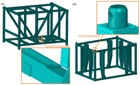
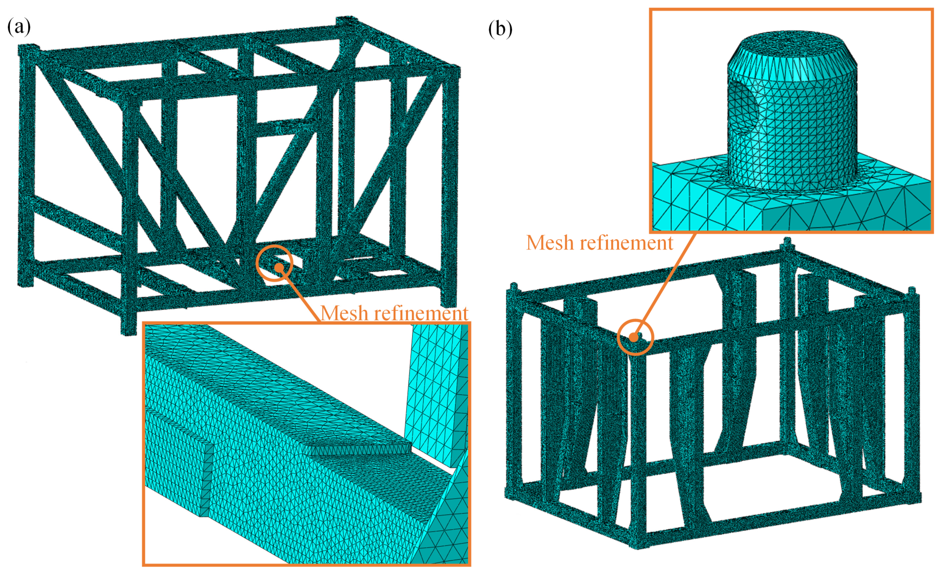
Under the aforementioned hierarchical meshing strategy, 776,297 elements were generated for the upper frame, and 736,480 elements were generated for the lower frame, culminating in a total of approximately 1.51 million elements. According to the default mesh quality inspection criteria in Abaqus, the proportion of error elements in the upper frame was 0%, and the number of warning elements was 6851, accounting for less than 1%. Similarly, the proportion of error elements in the lower frame was 0%, with 7355 warning elements, also accounting for less than 1%. This demonstrates that this level of discretization achieves effective control over the calculation scale of the overall model while ensuring computational precision in critical stress regions, and is fully capable of satisfying the numerical stability requirements for stiffness response and contact force transmission in transient dynamic analysis. The specific structural configuration and independent grid distribution morphology are shown in Figure 3.
Figure 3.
Spatial discretization and independent meshing model of the ROV LARS. (a) Finite element mesh model and local refinement features of the upper frame; (b) Finite element mesh model and connection details of the lower frame.
2.3. Load Distribution Settings
The multi-source dynamic auxiliary loads of the system are precisely mapped to corresponding geometric domains in the form of uniform surface loads or multi-point kinematic constraints. Based on marine hydrodynamics theory, the net weight of the ROV body and its added mass effect in water were incorporated into the model. All load vector directions are applied along the gravity acceleration vector in the global coordinate system.
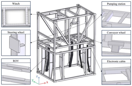
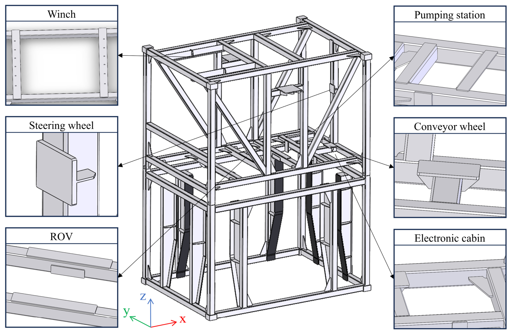
The mass parameters and spatial distribution locations of the core loads possess explicit mechanical mapping relationships. To visually present the physical boundaries and mechanical action points of each subsystem on the main rigid frame, Figure 4 shows the schematic diagram of load distribution and loading positions of the LARS. Based on this figure, the 2450 kg upper frame winch system and the 95 kg directional sheave are loaded onto their corresponding mounting beam bases through uniform mass matrices, respectively; in addition, the 390 kg transmission assembly and the 240 kg pump station system are equivalently mapped to specific flange mounting nodes. The specific quantitative distribution of the aforementioned conventional loads is detailed in Table 2.
Figure 4.
Schematic diagram of load distribution and loading positions of the LARS.
Table 2.
Mass and load distribution of key components of the ROV LARS.
When defining the load boundaries under transient impact excitation, considering the physical constraint characteristics of external auxiliary support equipment and the nonlinear motion of the mother ship under complex sea conditions, an effective load vector that decouples gravity and inertial forces was constructed.
Under the forced motion state of the mother ship deck, the generalized kinematic response of the LARS can be derived from the Newton-Euler equations:
where , , are the global mass matrix, damping matrix, and stiffness matrix of the system including the ROV, respectively; , , are the absolute acceleration, velocity, and displacement vectors of the system nodes; and is the generalized external excitation load sustained by the system. However, in specific extreme transient impact conditions, external excitation is predominantly input into the system through the forced acceleration of the boundary attitude. Under these circumstances, for the ROV node domain without direct environmental loads, the generalized external force it bears is essentially entirely composed of the dynamic reaction force of the ROV itself.
To accurately isolate the physical effects of the steady-state field and the transient field in implicit dynamic integration, this study redefines the equivalent external load in this node domain as the effective load vector , decomposing it into a transient inertial force component and a reduced equivalent static gravity component:
The transient inertial force component is jointly determined by the spatial mass properties of the ROV and the six-degree-of-freedom transient acceleration field:
To precisely capture the spatial dynamic response, the constant inertial mass matrix of the ROV under full-load state is characterized by a spatial six-degree-of-freedom diagonal matrix:
where is the absolute mass of the ROV under full load; , , and are the principal moments of inertia of the ROV around the local coordinate axes, respectively. represents the extracted node transient acceleration vector.
For the gravity component, considering the physical constraints and load-sharing characteristics of the external auxiliary support equipment on static loads, a static gravity reduction coefficient is introduced:
where is the gravitational acceleration vector. In shipborne dynamic operating conditions, 0.1 is adopted to equivalently account for the vast majority of steady-state static loads shared by the hoisting system in actual operations. The physical basis for taking the static gravity reduction coefficient 0.1 can be explained as follows. In actual operations of the LARS, the vast majority of the static gravity load of the ROV is directly borne by the external auxiliary support equipment and transmitted to the deck base, making the main frame primarily act as a spatial limiter and guide under static conditions, rather than a core force transmission member. However, this coefficient is not absolutely zeroed in the dynamic modeling, but is set to 0.1, primarily to account for the elastic yielding of the main hoisting mechanism under heavy loads and the nonlinearity of system stiffness distribution. Furthermore, from the perspective of finite element numerical solving, retaining this minor reduced gravity can provide necessary initial pre-stress for critical areas of the frame, thereby effectively suppressing numerical high-frequency oscillations that might occur at the initial moment of impact during implicit dynamic integration. This maintains the stability of contact pair states and provides a rigorous physical baseline for evaluating the authentic mechanical responses of the equipment under extreme transient impacts. The specific value of the gravity reduction coefficient ( 0.1) is determined based on the empirical load-sharing characteristics of the LARS under deck-secured conditions, where approximately 90% of the static vertical load is directly transferred to the hull base via auxiliary locking and supporting mechanisms. Retaining this 10% residual gravity is not arbitrary; mathematically, it introduces a continuous baseline pre-stress that characterizes the residual contact pressure on the guide rails. This effectively eliminates rigid-body singularities and guarantees the convergence of the nonlinear implicit integration during the initial impact phase.
Synthesizing the above mechanical derivations, the final dynamic response load distribution within the ROV node domain is characterized as:
While ensuring high-frequency inertial force calculation accuracy, this decoupling strategy avoids the excessive superimposition of steady-state gravity fields, providing a rigorous physical premise for the subsequent evaluation of structural dynamic responses under extreme inertial impacts.
2.4. Operating Conditions and Boundary Conditions
To systematically evaluate the structural response characteristics of the marine ROV LARS under different service states, static operating conditions were defined within a unified finite element modeling framework. Such conditions are utilized to analyze the load-bearing capacity and overall stiffness performance of the structure dominated by the quasi-static gravity field, mainly encompassing the lifting state and the storage state. In the lifting condition, the LARS is in a suspended phase; the model applies six-degree-of-freedom full constraints at the four standard corner nodes on the top of the upper frame to equivalently represent the rigid connection conditions of multi-point hoisting. All system auxiliary loads, structural self-weight, and the unreduced full-load gravity of the ROV are applied vertically in the form of standard gravitational acceleration. In the storage condition, the device is secured to the mother ship deck; the model applies full-DOF constraints at the four fixing bases at the bottom of the lower frame, while the load distribution remains identical to the lifting condition. This condition focuses on evaluating the stress distribution characteristics and potential stress concentration areas of critical structural nodes under long-term static loads.
The structural dynamics analysis conducted in this study targets severe operational scenarios typically encountered in Sea State 5 to 6. Specifically, the low-frequency ±15° pitch and ±45° roll conditions represent the severe low-frequency motions of the mother ship induced by large-amplitude ocean waves. The 1 g transient step acceleration conditions are designed to mathematically define the extreme, high-frequency impact loads caused by unpredictable wave slamming events, vessel transient heave, or the abrupt slack-to-tension snapping of the lifting cables during air-water interface crossing. To simulate these influences on the structure, swaying conditions and transient acceleration conditions are further defined in the model. In such conditions, to avert global rigid body motion, full-DOF constraints are applied simultaneously to the four corner pieces at the top of the upper frame and the four fixing bases at the bottom of the lower frame. Meanwhile, the ROV mechanical decoupling strategy is introduced; that is, the vertical static gravity is reduced to 10% while the inertial mass remains unchanged, to more authentically reflect the actual working conditions. To ensure the continuity of the dynamic response, angular displacement inputs are applied in the form of smooth sine functions, where the pitch condition corresponds to a ±15° periodic swing of the system around the Y-axis (period of 10 s), and the roll condition corresponds to a ±45° periodic swing around the X-axis (period of 14 s). Such conditions are primarily used to evaluate the dynamic stability and stress response characteristics of the structure under low-frequency wave excitations.
Aiming at the high-frequency impact loads triggered by severe hull motions in extreme sea states, transient acceleration conditions are defined to assess the ultimate dynamic response of the structure. In such conditions, the model applies full-constraint boundary conditions at eight key support points (upper and lower), and adopts the gravity reduction strategy while keeping the ROV inertial mass unchanged, with the system’s initial displacement and velocity both set to zero. By applying step acceleration loads with a duration of 1 s, four typical impact conditions are constructed: a 2 g downward vertical acceleration, a 1 g upward vertical acceleration, and 1 g lateral and longitudinal accelerations along the Y-axis and X-axis directions, respectively. The aforementioned conditions are utilized to analyze the stress concentration and transient displacement response features of the structure under different impact directions. All dynamic responses are solved based on the implicit integration method. Through the coupled computation of the mass matrix, damping matrix, and stiffness matrix, the numerical simulation of the transient impact process is achieved.
3. Simulation Results and Analysis
3.1. Static Response Analysis
In this section, the von Mises equivalent stress criterion is used as the theoretical basis for structural yield and failure assessment. The macroscopic bearing distribution laws and structural flexural stiffness characteristics of the LARS under the quasi-static gravity field were systematically extracted and analyzed.
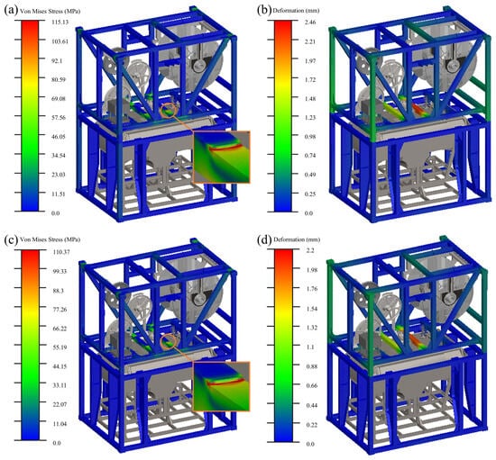
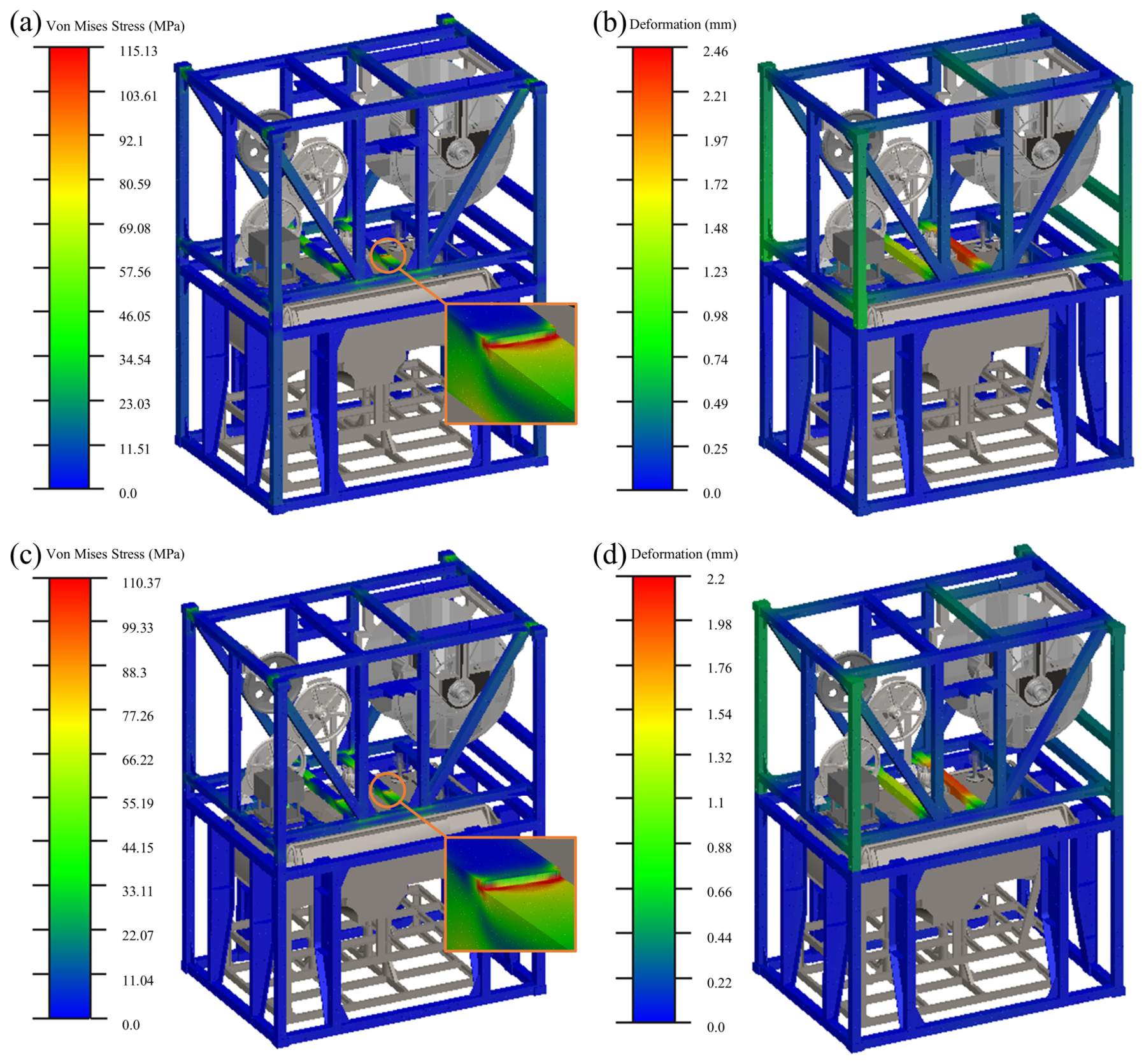
Under the storage condition, the four fixing bases at the bottom of the LARS are subject to full constraints. The transmission path of the system’s core loads shifts from the upper suspended components downward, eventually converging to the deck base through the vertical column network. Static finite element solving results, as shown in Figure 5a, indicate that the equivalent stress distribution across the structure is relatively smooth, with a local peak stress of 115.13 MPa. This high stress gradient region is primarily concentrated at the ROV loading point of the middle beam. Mechanical analysis reveals that this is due to the mutation of the geometric cross-section’s bending modulus, causing local congestion and shear concentration of the stress flow as it transmits along the beam. Under the collaborative constraints of multi-point rigid support boundaries, as shown in the deformation field in Figure 5b, the overall macroscopic maximum displacement is only 2.46 mm, mainly occurring in the middle frame area with the largest unsupported span. This deflection value is far below the elastic yield limit of the material, indicating that the system’s static support stiffness possesses a sufficient safety margin.
Figure 5.
Cloud maps of static responses: (a) von Mises equivalent stress distribution in storage condition; (b) Structural deformation displacement distribution in storage condition; (c) von Mises equivalent stress distribution in lifting condition; (d) Structural deformation displacement distribution in lifting condition.
Under the lifting condition, the mechanical boundary conditions transition to a four-point suspension at the top. The macroscopic mechanical characteristics are manifested as a composite coupling state of axial tension and local bending moments transitioning from the top hanging points to the middle bearing beam. Combined with the calculation cloud map in Figure 5c, the maximum von Mises stress is 110.37 MPa, precisely locked in the geometric curvature transition zone between the upper frame’s middle bearing beam and the locking mechanism. As the main force transmission hub bearing the 5500 kg core weight of the ROV, this area sustains a significant normal tensile stress component. Verification based on the 275 MPa nominal yield strength of the TA2 titanium alloy yields a calculated safety factor of 2.49 for this high-stress zone. Observing the displacement distribution in Figure 5d, the system’s maximum deformation exhibits a controlled vertical elastic deflection in the middle, with a peak displacement of 2.20 mm, indicating that the upper bearing beam possesses tensile cross-sectional characteristics and overall bending stiffness that meet operational requirements.
3.2. Low-Frequency Sway Response Analysis
During shipborne operations, the wave-induced low-frequency alternating eccentric load is a critical physical boundary for testing the structural fatigue life and dynamic attitude adaptability of marine equipment.
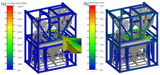
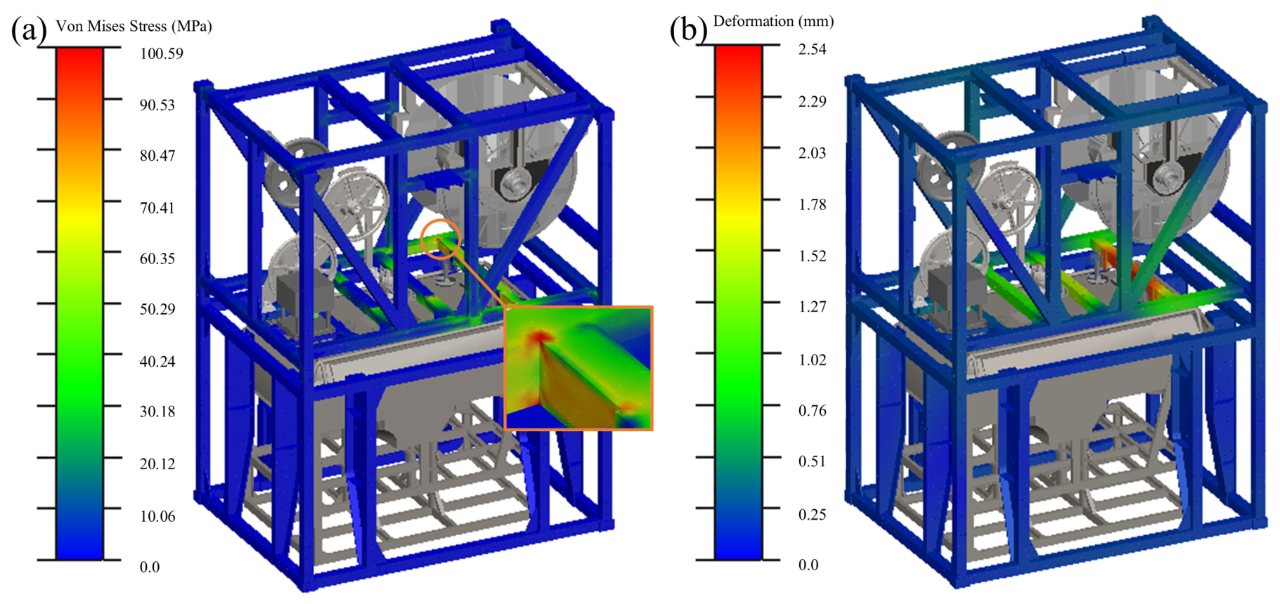
Under the pitch condition (±15°), the system gravity vector generates dynamic periodic components along the global longitudinal axis, inducing asymmetrical longitudinal shear effects at the front and rear ends of the structure. As shown in the stress field distribution in Figure 6a, the maximum equivalent stress is 100.59 MPa, concentrated in the transition area between the upper frame beam and the mounting surface of the buffer mechanism. Due to the large geometric span and reasonable sectional moment of inertia distribution of the transverse beam, the alternating eccentric load is fully dissipated within the material’s elastic deformation domain as strain energy. The displacement cloud map in Figure 6b shows that the global maximum relative deformation displacement is only 2.54 mm, with no local buckling or instability distortion excited, demonstrating the system’s excellent longitudinal attitude stability under long-period wave excitation.
Figure 6.
Cloud maps of dynamic responses in pitch (±15°) condition: (a) von Mises equivalent stress distribution; (b) Structural deformation displacement distribution.
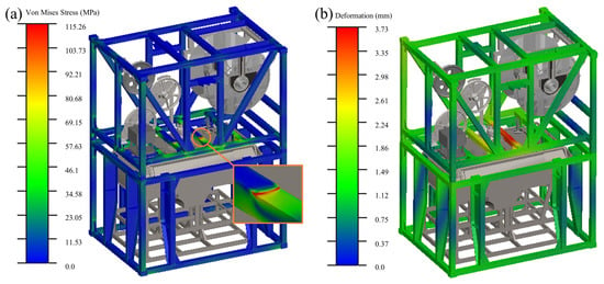
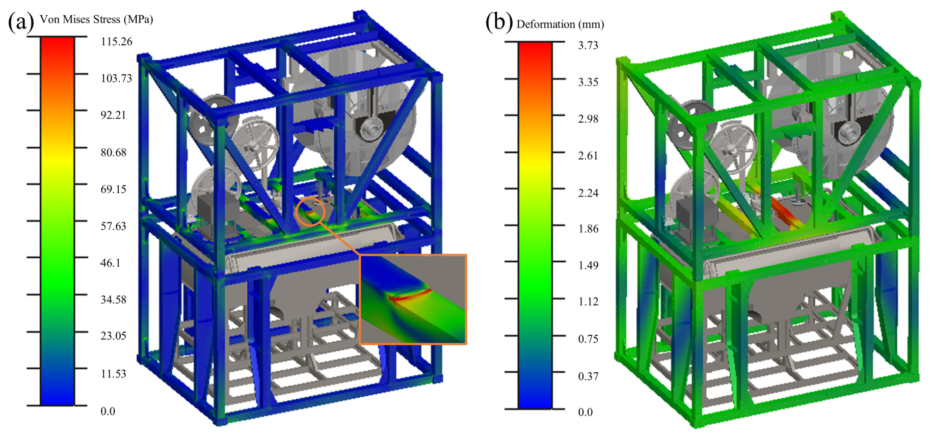
Under the roll condition (±45°), the structure is subjected to the superimposed action of the lateral dynamic projection force of its self-weight vector and the Coriolis centrifugal force generated by the system’s follow-up motion, leading to a significant increase in the lateral boundary reaction forces along the main force transmission path. Simulation results in Figure 7a show the peak stress climbing to 115.26 MPa, with high stress concentration zones converging on the cross-section of the middle bearing beam. This indicates that in a tilted state, the middle beam acts as a structural constraint node resisting system shear deformation, forming an energy transmission channel for lateral inertial loads. Although local stress increases accordingly, the titanium alloy remains within the linear elastic operating range. Meanwhile, Figure 7b shows that the structural maximum deformation displacement of 3.73 mm evolves steadily, reflecting the rigid frame system’s adequate dynamic roll resistance under low-frequency loads.
Figure 7.
Cloud maps of dynamic responses in roll (±45°) condition: (a) von Mises equivalent stress distribution; (b) Structural deformation displacement distribution.
3.3. Transient Acceleration Response Analysis
Acceleration conditions fall within the scope of transient dynamics, primarily examining the physical response characteristics of the rigid structural frame during the absorption and transmission of high-frequency transient impact kinetic energy.
Within the implicit transient integration system, the mechanical essence of the system’s resistance to high-frequency acceleration impact is the dynamic transformation and balance of different forms of physical energy. For any time step , the global energy conservation equation of the entire LARS can be described as:
To further reveal the mechanical evolution mechanism of this transient response process, the terms in the energy balance equation are decoupled and expanded into matrices:
where is the macroscopic kinetic energy dominated by the 5500 kg ROV inertial mass; is the internal elastic strain energy absorbed by the frame network through deformation; is the viscous dissipation energy, numerically equivalent to the cumulative integral of global damping resistance over the relative velocity field; and on the right side is the cumulative external work performed by the effective load vector to drive the transient response.
Since the initial rigid frame lacks an explicit physical dissipation mechanism, the damping term consists only of negligible intrinsic material damping. According to the principle of energy conservation, the peak external work from high-frequency impact is almost entirely converted into internal elastic strain energy and structural kinetic energy . This transmission mode, lacking effective energy dissipation, reveals the mechanical necessity of surging peak stresses and large transient displacements when the base frame sustains lateral and longitudinal ultimate impacts, establishing a theoretical premise for active vibration reduction.
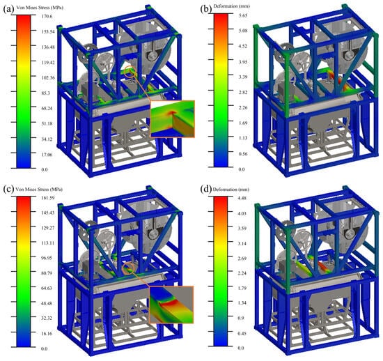
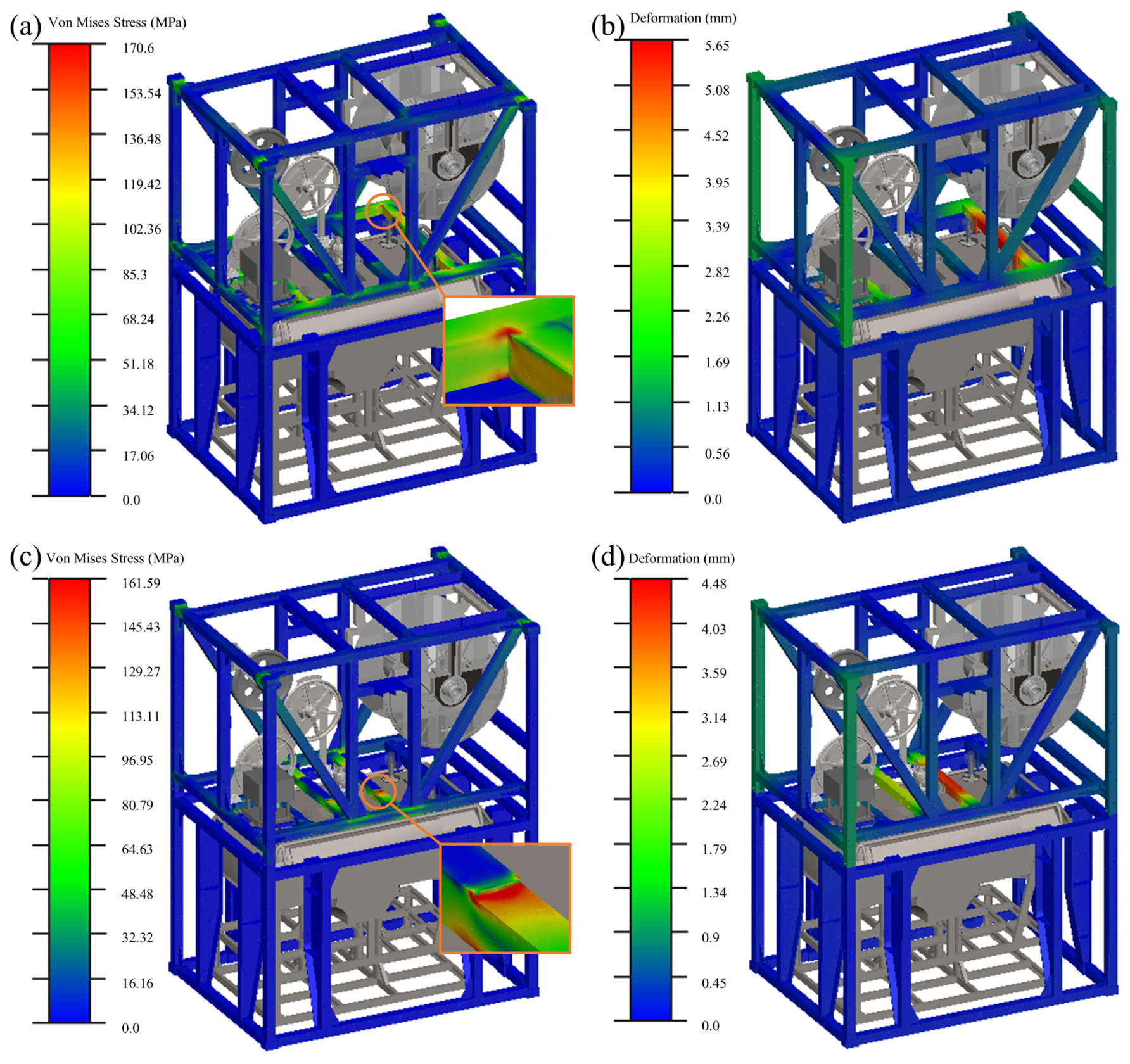
In the vertical impact characteristic spectrum analysis, although the ROV’s static gravity is shared by external support, its full inertial mass excites a transient inertial downward pressure during the 2 g downward acceleration condition. As shown in Figure 8a,b, the system stress reaches 170.60 MPa, with high stress flow primarily conducting down the four corner bearing columns to the base. Due to asymmetrical topology, the left transverse beam and the side beam form a rigid constraint through connections, whereas the right transverse beam is relatively independent, resulting in differences in vertical elastic response between the left and right sides, with a peak of 5.65 mm. Under the 1 g upward acceleration condition, the system exhibits inertial unloading and structural rebound. Figure 8c,d show a local peak stress of 161.59 MPa and a maximum reverse deflection of 4.48 mm, indicating that the multi-column support network has sufficient design parameter reserves for longitudinal loads.
Figure 8.
Cloud maps of transient acceleration responses: (a) von Mises equivalent stress in downward acceleration; (b) Displacement in downward acceleration; (c) von Mises equivalent stress in upward acceleration; (d) Displacement in upward acceleration.
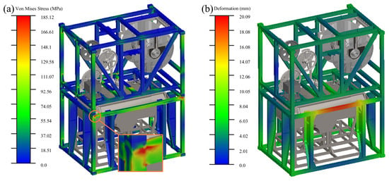
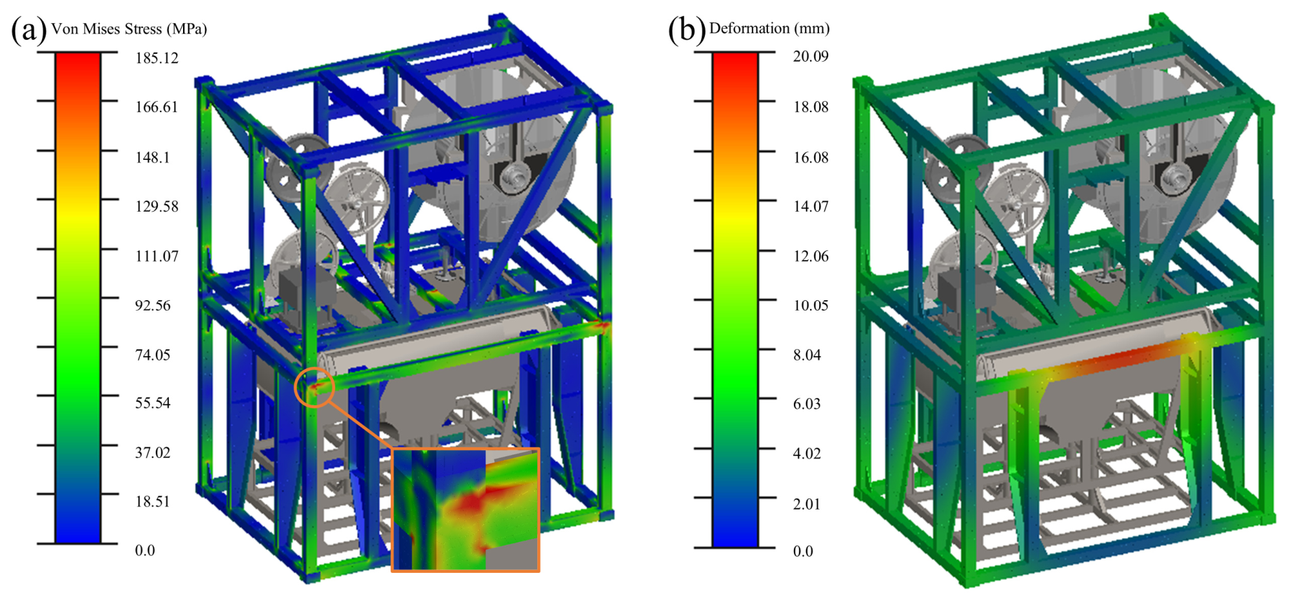
In horizontal plane transient impact analysis, more intense dynamic characteristics appear. Under 1 g lateral acceleration, the 5500 kg absolute inertial mass of the ROV remains unreduced and collides with the lower frame anti-collision structure due to inertial lag. As shown in Figure 9a, kinetic energy is converted into strain energy, causing the side beam’s equivalent stress to jump to 185.12 MPa. Figure 9b reveals a 20.09 mm transient deformation at the upper part of the lower frame, increasing lateral dynamic instability probability.
Figure 9.
Cloud maps of transient responses in lateral acceleration (1 g): (a) von Mises equivalent stress distribution; (b) Structural deformation displacement distribution.
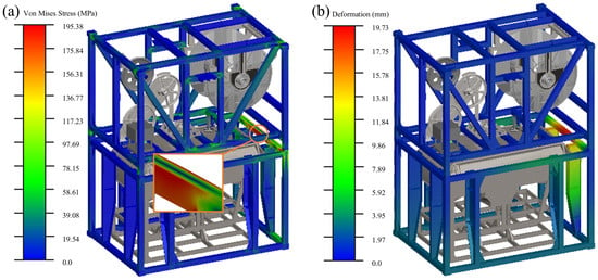
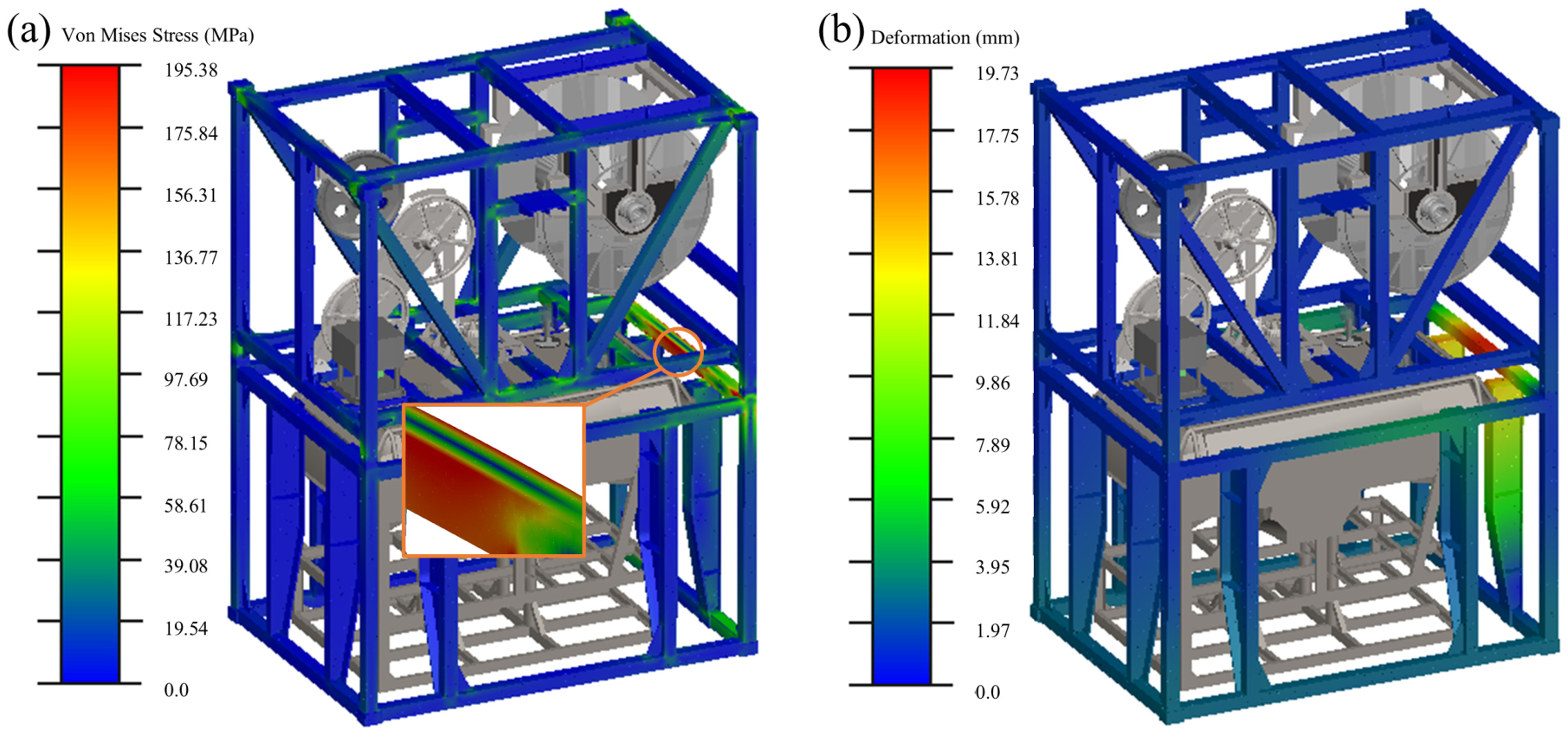
Similar high displacement responses occur under 1 g longitudinal acceleration. Without a buffer mechanism, impact kinetic energy is conducted directly from the bellmouth nodes to the main bearing longitudinal beams. As shown in Figure 10a, coupling of transient shear and tensile stress fields causes significant stress concentration, with maximum von Mises stress reaching 195.38 MPa. The transient safety factor drops to 1.41. Figure 10b records a 19.73 mm longitudinal deformation, posing a risk of internal structural interference and component damage.
Figure 10.
Cloud maps of transient responses in longitudinal acceleration (1 g): (a) von Mises equivalent stress distribution; (b) Structural deformation displacement distribution.
3.4. Comprehensive Evaluation of Mechanical Responses
To quantitatively present the mechanical transfer laws under all sea conditions, Table 3 summarizes core simulation values for the eight typical service conditions.
Table 3.
Summary of mechanical response results for typical operating conditions of the LARS.
Comprehensive analysis shows that while the base frame performs adequately under vertical loads and low-frequency sway, it faces physical performance limitations under high-frequency transient acceleration in horizontal planes, establishing the engineering necessity for active vibration reduction and displacement constraint optimization.
4. Structural Vibration Reduction Optimization and Comparative Verification
4.1. Equivalent Modeling of Viscoelastic Damping
Based on the previous analysis of transient acceleration impact responses, the basic rigid frame exhibits significant physical performance limitations when dealing with high-frequency inertial impacts in the horizontal plane. Due to the lack of corresponding displacement constraints and kinetic energy dissipation mechanisms, the system generates large transient deformations and local stress concentrations. To overcome this structural defect, this paper proposes an optimization scheme involving the symmetrical addition of four sets of flexible buffer mechanisms on the transverse and longitudinal inner walls of the lower frame.
In the structural transient dynamics finite element model, performing 3D mesh discretization on polymer rubber or hydraulic buffer solids would introduce complex hyperelastic material constitutive models and extensive nonlinear contact calculations. This would not only significantly increase the computational cost but also easily trigger numerical divergence due to mesh distortion. Therefore, this study adopts a dynamic equivalent modeling method for the buffer mechanisms. Specifically, the buffer mechanism abandons traditional solid geometric modeling and instead utilizes a viscoelastic damping boundary for discretization. In the finite element software, this damping boundary is defined as a 1D translational spring-damper connection element, with its end nodes connected to the main load-bearing beam of the lower frame and the external auxiliary support mechanism, respectively. The external auxiliary support mechanism provides a rigid ground boundary in this model, while the spring-damper unit acts as an energy dissipation component connecting the main system and the external boundary.
From the perspective of dynamic energy conversion, the mechanical response of this non-invasive damping boundary follows the Kelvin-Voigt viscoelastic constitutive relationship. The generated dynamic damping resistance is formed by the linear superposition of the elastic restoring force component and the viscous damping dissipation component. The elastic element is responsible for converting the transient collision kinetic energy into the structural elastic potential energy for temporary storage to avoid rigid bottoming out; the viscous damping element generates resistance through the relative velocity field, irreversibly converting this portion of mechanical energy into heat for dissipation.
To precisely quantify the mechanical evolution logic of this equivalent unit during a single transient impact, its constitutive equation, dissipated energy integral, and momentum conversion relationship based on the impulse theorem are unified and characterized as follows:
where is the total transient damping force output by the buffer mechanism; is the stiffness coefficient of the equivalent unit; is the viscous damping coefficient; and represent the transient relative compression displacement and instantaneous collision velocity, respectively; and is the total mechanical energy dissipated by the non-invasive damping boundary within the response period of a single transient impact.
The core purpose of introducing this equivalent boundary is to utilize viscoelastic deformation to extend the response time of collision momentum transfer. According to the impulse theorem in the equation set, given a certain total momentum change, the intervention of the energy dissipation integral and the significant extension of the collision response time can effectively reduce the peak transient excitation force transmitted to the main frame in both horizontal directions. This dual modulation mechanism based on “energy dissipation” and “time-scale stretching” constitutes the core mechanical motivation of the vibration reduction optimization strategy in this study. By fundamentally altering the momentum transfer path, this approach directly addresses the dynamic instability issues observed in the original rigid frame under horizontal impacts. The viscoelastic elements provide necessary dynamic anti-sway stiffness to effectively curb destructive transient lateral and longitudinal displacements, thereby preventing global dynamic instability. Simultaneously, the viscous damping component acts as an efficient energy dissipator, converting high-frequency concentrated inertial impact kinetic energy into heat, which ensures the structural stability of the extensive LARS model under unpredictable extreme horizontal loads.
Regarding the specific numerical development of the viscoelastic elements, the parameters are calibrated based on the peak structural kinetic energy and permissible deformation limits. The equivalent stiffness coefficient is quantified to strictly bound the maximum transient deformation within the geometric clearance of the anti-collision structures. Concurrently, the viscous damping coefficient is parameterized to approach the critical damping ratio of the local collision mode. This specific quantitative matching inherently avoids secondary structural rebounds caused by under-damping and the excessive localized reaction forces induced by over-damping, thereby optimizing the energy dissipation efficiency during the millisecond-level impact window.
4.2. Lateral Impact Vibration Reduction Analysis
In the 1 g lateral inertial excitation field, the spring-damper units symmetrically arranged along the transverse direction play an efficient role in energy absorption and displacement limitation for the lateral sway of the system.
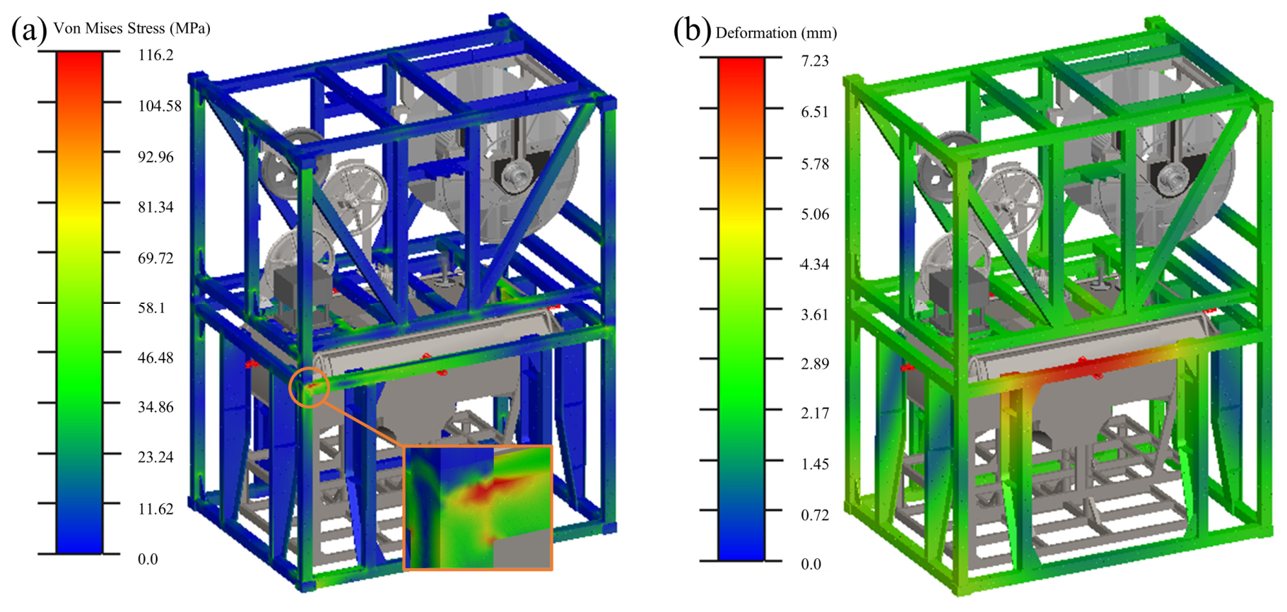
The intervention of damping elements essentially increases the local lateral dynamic impedance and enhances the equivalent damping ratio of the overall frame. As shown in Figure 11b, the original transient large deformation phenomenon is effectively suppressed, with the global maximum relative displacement response amplitude sharply converging from 20.09 mm in the unbuffered state to 7.23 mm. This forced convergence of displacement prevents the massive ROV mass from establishing destructive relative kinetic energy within internal clearances, thereby effectively weakening the lateral whipping effect. Along with the dynamic convergence of the macroscopic displacement field, the local equivalent peak stress induced by lateral distortion and large displacement extrusion also decreases significantly. As shown in Figure 11a, the maximum von Mises stress of the optimized system drops from 185.12 MPa to 116.20 MPa, and the safety factor of the corresponding nodes increases to 2.37. Comparative analysis shows that the load distribution across various bearing beams and the lateral frame is more uniform, with no obvious uneven load allocation, and the lateral impact resistance is comprehensively improved.
Figure 11.
Comparison of dynamic responses before and after optimization under 1 g lateral acceleration: (a) von Mises equivalent stress distribution after optimization; (b) Deformation displacement distribution after optimization.
4.3. Longitudinal Impact Vibration Reduction Analysis
The optimized dynamic model with added spring-damping boundaries was subjected to implicit integration solving under a 1 g longitudinal step impact field. The benchmarking results demonstrate that after introducing the damping optimization scheme, the dynamic response of the structure under longitudinal inertial impact is significantly controlled.
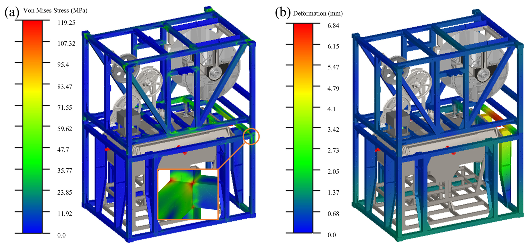
In the initial stage of longitudinal excitation, the damping elements arranged longitudinally generate reverse viscous damping dissipation forces accompanying the variation in the relative velocity field. This dissipation force acts like a mechanical low-pass filter, reducing high-frequency acceleration peaks and slowing down the physical collision between the ROV mass and the main frame. Finite element calculation results in Figure 12a show that the high stress concentration at the bellmouth connection area after optimization is relieved. The original stress accumulation in the geometric mutation zone is improved, the stress distribution becomes smoother, and loads are transferred along the force transmission path to the surrounding buffer bases and frame network. The global maximum von Mises stress of the system decreases from 195.38 MPa before optimization to 119.25 MPa. Verified against the yield strength of TA2 titanium alloy, the local safety factor of this node rises from 1.41 to 2.31, indicating that the longitudinal safety margin of the structure has returned to a reasonable range for engineering design.
Figure 12.
Comparison of dynamic responses before and after optimization under 1 g longitudinal acceleration: (a) von Mises equivalent stress distribution after optimization; (b) Deformation displacement distribution after optimization.
Regarding displacement response, as shown in Figure 12b, under the constraint of the spring restoring force matrix, the maximum longitudinal transient deformation displacement of the system converges from 19.73 mm to 6.84 mm. The convergence of transient displacement amplitude effectively reduces the objective risk of internal physical interference and component impact damage, ensuring the overall dynamic survivability of the system.
4.4. Comprehensive Evaluation of Optimization Results
To quantitatively elucidate the optimization effects of the viscoelastic buffer system, Table 4 summarizes the comparative data of core dynamic and kinematic indicators under two types of extreme horizontal impact conditions.
Table 4.
Quantitative comparison of dynamic mechanical performance before and after structural optimization under extreme horizontal impact conditions.
Multi-condition mechanical benchmarking results indicate that the non-invasive viscoelastic buffer system constructed in this study significantly improves the impact resistance of offshore operation equipment in extreme sea states. Comparing the improvement magnitudes, the maximum stress reduction in the structure exceeds 37%, while the constraint effect on transient displacement is even more significant, with reductions exceeding 64%.
Analysis of the micro-mechanisms of structural dynamic energy dissipation reveals that the non-invasive buffer strategy essentially constructs a generalized Kelvin-Voigt viscoelastic damping boundary at vulnerable structural nodes. When encountering extreme transient impacts, this boundary, through the synergy of elastic and viscous damping mechanisms, completely alters the momentum transfer path of the original rigid frame. The elastic component provides necessary dynamic anti-sway stiffness, effectively curbing destructive transient displacements on the scale of 20 mm and preventing secondary collision damage from the massive mass block. Simultaneously, the viscous damping component acts as an efficient energy dissipator, irreversibly converting high-frequency concentrated inertial impact kinetic energy into heat. This flexible energy dissipation constraint mechanism successfully transforms high-frequency strong excitations into low-frequency weak responses, fundamentally weakening stress accumulation during load transmission.
In terms of dynamic safety assessment, the extreme safety factor of core nodes before optimization once approached the dangerous threshold of 1.41. Given the extreme uncertainty of wind, wave, and current coupled excitations in pelagic marine operations and long-term fatigue accumulation, such a thin safety margin could easily lead to local yielding or even global instability under sudden sea conditions. After introducing the damping boundary, the minimum safety factors in both transverse and longitudinal directions steadily rose above 2.3. This substantial recovery not only brings the stress state of the main force transmission hubs fully back into the linear elastic safety envelope but also reserves sufficient dynamic bearing redundancy for the equipment to cope with extreme conditions such as mother ship wave slamming or re-entry into water.
From the macroscopic perspective of engineering application, traditional impact protection designs for marine equipment often rely on physical strengthening of the full frame cross-section by increasing wall thickness or adding rigid anti-collision supports. This structural hardening strategy inevitably leads to a sharp increase in parasitic system mass, exerting negative effects on the mother ship’s deck load distribution and overall stability. The local non-invasive flexible treatment strategy proposed in this study achieves a significant improvement in equipment survivability without altering the original macroscopic dimensions of the main frame or significantly increasing the system’s self-weight. This optimization result fully confirms the unique advantages of the strategy overcoming weight penalties and excessive stiffness, highly aligning with the engineering development trend of modern heavy-duty special marine operation equipment toward lightweight design, high reliability, and strong environmental adaptability.
5. Conclusions
This paper conducted a systematic structural dynamics analysis and vibration reduction optimization study on a marine ROV launch and recovery system (LARS) regarding its structural safety and transient impact resistance in complex marine environments. Based on multi-body dynamics and solid mechanics theories, a high-fidelity spatially discretized finite element model was established, and a dynamic modeling method decoupling static gravity from transient inertial mass was introduced to evaluate structural response characteristics under various typical conditions. On this basis, non-invasive vibration reduction optimization was achieved by introducing viscoelastic damping boundaries, leading to the following primary conclusions:
- (1)
- Under conventional conditions (statics and low-frequency sway), the basic rigid frame structure exhibits good load-bearing performance and structural stiffness. Simulation results show that under storage and lifting conditions, as well as ±15° pitch and ±45° roll conditions, the equivalent stresses are below the material yield limit, and the maximum relative displacement is controlled within 5.65 mm. This indicates that the existing structural topology meets strength and stiffness requirements under routine service conditions and possesses stable low-frequency dynamic response capabilities.
- (2)
- Under high-frequency transient impact conditions in the horizontal plane, the pure rigid connection system exhibits significant dynamic instability characteristics. In 1 g lateral and longitudinal acceleration conditions, due to the lack of effective displacement constraints and energy dissipation mechanisms, the 5500 kg inertial mass of the ROV causes impact kinetic energy to concentrate into local strain energy. Before optimization, the structure generates large transient deformations of 20.09 mm and 19.73 mm, respectively, while maximum equivalent stresses at critical nodes reach 185.12 MPa and 195.38 MPa. When compared to the 275 MPa nominal yield strength limit of the TA2 titanium alloy, this baseline result suggests that traditional rigid frames face obvious safety margin deficiencies and structural failure risks under high-frequency impact conditions.
- (3)
- After introducing the non-invasive vibration reduction strategy based on viscoelastic damping boundaries, the structural impact response is significantly improved. Damping elements effectively suppress transient responses by extending momentum transfer time and dissipating impact energy. Optimization results show that maximum equivalent stresses in lateral and longitudinal conditions decrease to 116.20 MPa and 119.25 MPa, respectively, with reductions exceeding 37%; corresponding transient displacements decrease to 7.23 mm and 6.84 mm, with reductions exceeding 64%. This strategy achieves a significant increase in the safety margin and uniform load distribution without increasing structural mass or altering main dimensions.
In summary, the dynamic decoupled modeling method and the non-invasive viscoelastic vibration reduction strategy proposed in this paper can effectively enhance the impact resistance of marine ROV launch and recovery systems under extreme conditions. This approach breaks through the limitations of traditional structural strengthening designs that rely on mass increase, providing a new technical path for the lightweight design and highly reliable operation of marine engineering equipment. Simultaneously, this research methodology possesses good promotion value for the impact protection design of other heavy-duty marine operation equipment. Future work will integrate scale model tests or actual sea state tests for further validation of the numerical model and conduct refined identification and engineering calibration of nonlinear damping parameters under multi-directional coupling conditions.
Author Contributions
Conceptualization, X.Q.; methodology, F.G.; software, J.W. and L.H.; validation, W.L.; data curation, W.L.; writing—original draft preparation, L.H., F.G. and J.W.; writing—review and editing, L.H., W.L., D.T. and W.X.; All authors have read and agreed to the published version of the manuscript.
Funding
This research was funded by the National Natural Science Foundation of China (NSFC) under Grant No. 52175124 and No. 52575546, and by the Hangzhou Key Scientific Research Program No. 2025SZD1A15.
Institutional Review Board Statement
Not applicable.
Informed Consent Statement
Not applicable.
Data Availability Statement
The original contributions presented in this study are included in the article. Further inquiries can be directed to the corresponding authors.
Conflicts of Interest
Author Jianfeng Wu was employed by the company Hangzhou Navigation Instrument Co., Ltd. The remaining authors declare that the research was conducted in the absence of any commercial or financial relationships that could be construed as a potential conflict of interest.
References
- Dalhatu, A.A.; Sa’ad, A.M.; de Azevedo, R.C.; de Tomi, G. Remotely Operated Vehicle Taxonomy and Emerging Methods of Inspection, Maintenance, and Repair Operations: An Overview and Outlook. J. Offshore Mech. Arct. Eng. 2023, 145, 020801. [Google Scholar] [CrossRef] [Scilit]
- Tran, C.; Gushkov, I.; Nordvik, K.; Roang, S.T.; Lysthaug, S.B.; Ommani, B.; Fossen, T.I.; Hassani, V.; Smines, V.; Johansen, T.A. Operability analysis of control system for ROV launch-and-recovery from autonomous surface vessel. Ocean Eng. 2023, 277, 114272. [Google Scholar] [CrossRef] [Scilit]
- Deng, Y.; Ren, X.; Nuernberg, M.; Tao, L. Launch and recovery of a work class ROV through wave zone in small offshore service vessel. Ocean Eng. 2024, 309, 118541. [Google Scholar] [CrossRef] [Scilit]
- Jiang, X.N.; Zeng, C.; Liu, J.; Gu, Q.; Wang, Z.Y.; Pan, H. Dynamic Modeling and Analysis on the Cable Effect of USV/UUV System Under High-Speed Condition. J. Mar. Sci. Eng. 2025, 13, 125. [Google Scholar] [CrossRef] [Scilit]
- Chen, M.S.; Yuan, G.B.; Li, C.B.; Zhang, X.X.; Li, L. Dynamic Analysis and Extreme Response Evaluation of Lifting Operation of the Offshore Wind Turbine Jacket Foundation Using a Floating Crane Vessel. J. Mar. Sci. Eng. 2022, 10, 2023. [Google Scholar] [CrossRef] [Scilit]
- Chen, M.S.; Yuan, G.B.; Li, B.; Li, C.B.; Ouyang, M.J.; Li, L.; Shi, W.; Han, Z.L.; Zhang, W.; Chen, Z.W. Dynamic analysis of lift-off operation of offshore wind turbine jacket foundation from the transportation barge. Ocean Eng. 2024, 301, 117443. [Google Scholar] [CrossRef] [Scilit]
- Zeng, F.X.; Zhang, N.C.; Huang, G.X.; Gu, Q.; He, M. Dynamic response of floating offshore wind turbines under freak waves with large crest and deep trough. Energy 2023, 278, 127679. [Google Scholar] [CrossRef] [Scilit]
- Li, W.; Zhao, S.X.; Liu, K.; Lu, H.C.; Fan, T.H. Dynamic Response Calculation Algorithm for Floating Offshore Wind Turbines Based on a State-Space Method of Transfer Function. Front. Energy Res. 2022, 10, 909416. [Google Scholar] [CrossRef] [Scilit]
- Liu, Y.S.; Liu, C.X.; Gao, X.M.; Tan, J.W. Multiphysics Finite Element Analysis and Optimization of Load-Bearing Frame for Pure Electric SUVs. Symmetry 2025, 17, 1143. [Google Scholar] [CrossRef] [Scilit]
- Romero-Tello, P.; Lorente-López, A.J.; Gutiérrez-Romero, J.E. Structural design optimization of pressure hull using genetic algorithm and finite element analysis. Int. J. Struct. Integr. 2025, 16, 60–84. [Google Scholar] [CrossRef] [Scilit]
- Qiu, M.; He, Y.P.; Lyu, Y.B.; Wang, Z.G.; Li, M.Z.; Zhou, Z.J.; Zhang, Y.K.; Lin, C.H. Structural Evaluation on the Floating Production Storage and Offloading Large Flow Gas Processing Module Based on FEM Analysis. Buildings 2024, 14, 3180. [Google Scholar] [CrossRef] [Scilit]
- Berardi, A.; Dellisanti, C.D.; Tarantino, D.; Ouette, K.S.L.; Leone, A.; Tamborrino, A. FEA for Optimizing Design and Fabrication of Frame Structure of Elevating Work Platforms. Appl. Sci. 2025, 15, 7356. [Google Scholar] [CrossRef] [Scilit]
- Guan, B.W.; Cheng, K.; Zhao, E.F. Experimental and Numerical Study of the Jib Connection Frame of a Wheeled Crane. Appl. Sci. 2025, 15, 4872. [Google Scholar] [CrossRef] [Scilit]
- Ma, L.; Ding, J.; Zhang, X.; Wang, W.; Zhao, X.; Sun, C.; Yang, Y. Analysis of dynamic response of offshore wind turbines subjected to ship impacts and the corresponding protection measures: A review. Front. Energy Res. 2024, 12, 1497210. [Google Scholar] [CrossRef] [Scilit]
- Yang, R.; Zhang, W.; Li, S.Y.; Xu, M.M.; Huang, W.; Qin, Z.H. Finite Element Analysis and Optimization of Hydrogen Fuel Cell City Bus Body Frame Structure. Appl. Sci. 2023, 13, 10964. [Google Scholar] [CrossRef] [Scilit]
- Lonkwic, P.; Przystupa, K.; Krakowski, T.; Ruta, H. Case Study of Support Frame Optimization Using a Distant Load. Sustainability 2020, 12, 974. [Google Scholar] [CrossRef] [Scilit]
- Lopez, A.; Iandiorio, C.; Milani, D.; Salvini, P.; Biancolini, M.E. Shape Optimization of Frame Structures Through a Hybrid Two-Dimensional Analytical and Three-Dimensional Numerical Approach. Eng. Proc. 2025, 85, 44. [Google Scholar] [CrossRef] [Scilit]
- Ghannadi, P.; Khatir, S.; Kourehli, S.S.; Nguyen, A.; Boutchicha, D.; Wahab, M.A. Finite element model updating and damage identification using semi-rigidly connected frame element and optimization procedure: An experimental validation. Structures 2023, 50, 1173–1190. [Google Scholar] [CrossRef] [Scilit]
- Wang, D.; Xie, C.; Liu, Y.; Xu, W.; Chen, Q. Multi-objective Collaborative Optimization for the Lightweight Design of an Electric Bus Body Frame. Automot. Innov. 2020, 3, 250–259. [Google Scholar] [CrossRef] [Scilit]
- Zeng, M.Y.; Tan, B.H.; Ding, F.; Zhang, B.J.; Zhou, H.T.; Chen, Y.C. An experimental investigation of resonance sources and vibration transmission for a pure electric bus. Proc. Inst. Mech. Eng. Part D-J. Automob. Eng. 2020, 234, 950–962. [Google Scholar] [CrossRef] [Scilit]
- Batista, E.D.; de Lazzari, J.A.; Matsubara, G.Y.; Pfeil, M.S.; Elias, R.N. Assessment of reinforcements for enhancing structural performance of cold-formed steel polygonal conical poles for antennas support. Lat. Am. J. Solids Struct. 2025, 22, 26. [Google Scholar] [CrossRef] [Scilit]
- Kumar, B.A.; Shashi, B. Finite element analysis of VGCF/pp reinforced square representative volume element to predict its mechanical properties for different loadings. Mater. Today Proc. 2021, 39, 54–59. [Google Scholar] [CrossRef] [Scilit]
- Huang, J.C.; Tian, K.P.; Ji, A.M.; Zhang, B.; Shen, C.; Liu, H.L. Research on the Construction of a Finite Element Model and Parameter Calibration for Industrial Hemp Stalks. Agronomy 2023, 13, 1918. [Google Scholar] [CrossRef] [Scilit]
- Xu, Y.S.; He, Q.; Guo, Y.Q.; Huang, X.H.; Dong, Y.R.; Hu, Z.W.; Kim, J. Experimental and theoretical investigation of viscoelastic damper by applying fractional derivative method and internal variable theory. Buildings 2023, 13, 239. [Google Scholar] [CrossRef] [Scilit]
- Zheng, G.Z.; Zhang, N.T.; Lv, S.T. The Application of Fractional Derivative Viscoelastic Models in the Finite Element Method: Taking Several Common Models as Examples. Fractal Fract. 2024, 8, 103. [Google Scholar] [CrossRef] [Scilit]
- Xu, Y.S.; Xu, Z.D.; Guo, Y.Q.; Huang, X.H.; Hu, Z.W.; Dong, Y.R.; Shah, A.A.; Dai, J.; Xu, C. Investigation of the Dynamic Properties of Viscoelastic Dampers with Three-Chain Micromolecular Configurations and Tube Constraint Effects. J. Aerosp. Eng. 2025, 38, 17. [Google Scholar] [CrossRef] [Scilit]
- Kasai, K.; Osabel, D.M.; Sato, D. Dynamic response characterization and simplified analysis methods for viscoelastic dampers considering heat transfer. Earthq. Eng. Struct. Dyn. 2023, 52, 27–50. [Google Scholar] [CrossRef] [Scilit]
- Takewaki, I.; Akehashi, H. Comprehensive review of optimal and smart design of nonlinear building structures with and without passive dampers subjected to earthquake loading. Front. Built Environ. 2021, 7, 631114. [Google Scholar] [CrossRef] [Scilit]
- Wu, Q.Y.; Jia, C.Y.; Liu, W.G.; Sun, J.B.; Chen, X.Y.; Zhu, H.P.; Wu, D. Experimental and numerical study on a novel viscoelastic-friction composite damper. Structures 2025, 75, 108840. [Google Scholar] [CrossRef] [Scilit]
- Hosseini, A.; Briseghella, B.; Giaccu, G.F.; Fenu, L. Integrated design framework for optimizing shape and Damper placement in steel gridshells under seismic loads. J. Build. Eng. 2025, 112, 113677. [Google Scholar] [CrossRef] [Scilit]
- Yang, J. Strength Calculation Method of Agricultural Machinery Structure Using Finite Element Analysis. Int. J. Adv. Sci. Comput. Appl. 2024, 15, 699–706. [Google Scholar] [CrossRef] [Scilit]
- Xie, T.C.; Huang, L.P.; Xu, J.W.; Guo, Y.; Ou, Y. Dynamic Analysis of Active Heave Compensation System for Marine Winch under the Impact of Irregular Waves. J. Mar. Sci. Eng. 2023, 11, 240. [Google Scholar] [CrossRef] [Scilit]
- Yu, X.Q.; Guo, Y.C.; Guo, S.X.; Liu, X.X.; Kong, Y.; Li, M.; Chen, W.M. Dynamic responses of ROV system experiencing vessel heave during deployment and recovery processes. Ocean Eng. 2024, 309, 118457. [Google Scholar] [CrossRef] [Scilit]
- Zhang, D.; Zhao, B.; Zhang, Y.; Zhu, K.; Yan, J. Study on Dynamic Characteristics and Fracture Failure of Rigid Truss Trawl System During Towing Process. J. Mar. Sci. Eng. 2025, 13, 586. [Google Scholar] [CrossRef] [Scilit]

Disclaimer/Publisher’s Note: The statements, opinions and data contained in all publications are solely those of the individual author(s) and contributor(s) and not of MDPI and/or the editor(s). MDPI and/or the editor(s) disclaim responsibility for any injury to people or property resulting from any ideas, methods, instructions or products referred to in the content. |
© 2026 by the authors. Licensee MDPI, Basel, Switzerland. This article is an open access article distributed under the terms and conditions of the Creative Commons Attribution (CC BY) license.