


Abstract
Forest planning and operational execution still often rely on separate office-based workflows, field inventories, and analogue tree-marking procedures, limiting direct communication between planners and field personnel. Mixed reality (MR) interfaces and forest digital twin concepts may help link planning decisions with field-level visualization and interaction. This study presents an initial proof-of-concept prototype for MR-based virtual tree tagging and field–office communication in forestry. The prototype integrates a Unity GE-based Forest Planner System, a Microsoft HoloLens 2-based Forest Worker System, and a locally hosted MagicOnion server for bidirectional client–server communication. Virtual trees with predefined stem diameters were created in Unity GE, and torus-shaped markers were implemented to support tree selection, color-coded designation, marker deletion, and visualization of predefined diameter-related attributes. Under controlled indoor conditions using a 5G mobile hotspot, both clients connected to the server and exchanged marker-related events. Marker creation, color assignment, deletion, and shared marker-state updates initiated from either client were reproduced in the corresponding system. The prototype demonstrates the functional feasibility of the core communication workflow but remains limited to a simulated environment.
1. Introduction
Augmented Reality (AR) and Mixed Reality (MR) are increasingly being explored as interfaces for embedding digital information into real-world environments. In forestry, their use has expanded from education and basic visualization toward operational applications, such as forest inventory, harvesting support, logistics, roundwood measurement, natural disaster management, and occupational safety [1,2]. This development is consistent with the broader transition to Forest 4.0. Despite these advances, a practical gap remains between office-based forest planning and field-level implementation. Forest planning commonly relies on field inventories and analogue tree-marking procedures, while operational execution depends on the accurate interpretation of these decisions under complex stand conditions. Conventional spray-paint marking and paper-based communication may be affected by fading, limited traceability, delays in updating information, and reduced flexibility when field conditions require modifications to the original plan. MR technologies could help address these limitations by transferring digital planning information directly into forest environments and making tree-level decisions more accessible to field personnel and machine operators [2].
De Miguel-Díez and Purfürst [2] identified several planning- and inventory-related MR use cases in forestry, including the visualization of parcel boundaries, stand attributes, forest road conditions, sample plot boundaries, and trees selected for felling or retention. A particularly promising application is virtual tree marking for silvicultural and harvesting operations, in which AR/MR systems could indicate trees selected for felling or retention while providing information on tree quality, operational constraints, and decision-support cues [2]. When linked to forest inventory and stand-level planning data, digital tree marking could improve operational accuracy, especially in dense or understory-rich stands where visibility is limited and conventional markings may be difficult to interpret. It could also support the protection of habitat trees and other retention elements. However, operational deployment remains constrained by technical and non-technical barriers, including limited device durability, short battery life, sensitivity to light conditions, restricted field of view, latency, reduced accuracy of georeferenced projections under forest canopies, high acquisition and licensing costs, data-protection and occupational-safety requirements [2]. The concept of a forest digital twin provides a suitable framework for integrating such information flows. Qiu et al. (2023) [3] described the forest digital twin as a digital carrier of forest resources that combines spatio-temporal data, 3D simulation engines, intelligent interactive environments, and forest management theory. For AR- and MR-based tree marking, this implies that virtual forest objects should not only be visualized, but should also be linked to spatially explicit information, operational decisions, and interactive feedback between planning and field environments. A specific research gap remains at the intersection of forestry digital twins, MR-based visualization, and operational tree marking. Related MR work has recently demonstrated the visualization of biodiversity indicators on real tree stems [4], while digital tree-designation studies have explored tablet-, imagery-, light detection and ranging (LiDAR)-, and desktop-based marking approaches.
However, to the best of our knowledge, no MR-based virtual tree-tagging system has yet been developed to support bidirectional field–office synchronization within a forestry digital twin workflow. The novelty of the present prototype therefore lies not in the use of MR visualization alone, but in its integration with virtual tree marking and bidirectional field–office synchronization within a forest digital twin-oriented workflow. Unlike previous AR/MR forestry applications that primarily support visualization, inventory, biodiversity assessment, or field guidance tasks, the proposed system combines an office-based Unity Game Engine (Unity GE) planning environment, a Microsoft HoloLens 2-based worker interface, and a server-mediated communication layer that synchronizes marker-related decisions between the two endpoints. This architecture enables tree-level marking decisions to be created, modified, deleted, and visually updated across the planner and worker systems, thereby establishing an initial technical foundation for interactive office–field coordination in digital tree-marking workflows.
Based on this research gap, the present proof-of-concept study was guided by three feasibility-oriented research questions: (i) whether a server-mediated architecture can establish bidirectional communication between an office-based Unity GE environment and a Microsoft HoloLens 2-based MR interface; (ii) whether marker-related events, including marker creation, color-coded designation, modification, and deletion, can be synchronized consistently between the two systems under controlled simulated conditions; and (iii) whether diameter-related information associated with virtual tree objects can be visualized through the MR interface as a preliminary step toward future augmentation of real trees. These questions are not intended to assess operational field performance, but to evaluate the technical feasibility of the proposed communication and visualization workflow at an early prototype stage.
To address these questions, this paper presents a proof-of-concept prototype for digital twin-supported virtual tree tagging and diameter-related visualization in forestry. The system links a Unity GE-based Forest Planner System to a Microsoft HoloLens 2-based Forest Worker System via a server-mediated communication layer. This initial development stage is not intended to demonstrate operational field performance, but to establish the technical foundation for subsequent real-tree augmentation and field-based validation.
2. Materials and Methods
2.1. Prototype Concept and System Architecture
The envisioned prototype was conceptualized as an MR data exchange system designed to connect office-based Forest Planners with Field Operators and support holistic decision-making in digital tree-marking processes. The system is intended to support forest inventory and planning workflows, as well as the subsequent implementation of harvesting operations. Its overall architecture comprises three main components: (i) the Forest Planner System, (ii) the Forest Worker System, and (iii) a Centralized Server System that serves as a bridge and enables communication between the two environments (Figure 1).
Figure 1.
Conceptual architecture and development pipeline of the envisioned prototype, including the Forest Planner System, the Forest Worker System, and the server-mediated communication layer. The diagram is schematic and not drawn to scale.
- The Forest Planner System is implemented in Unity GE, version 2022.3.39f1, developed by Unity Technologies (San Francisco, CA, USA). It serves as the main interface for office-based interaction with the virtual forest environment. Within this environment, virtual trees are generated and assigned spatial and georeferenced information. The Unity GE interface allows the Forest Planner to select individual virtual trees, assign markers to the selected trees, and apply color-coded labels. These markings correspond to management decisions communicated to field personnel in near real-time and are intended to be projected onto physical trees to visually indicate felling or retention designations. The Unity GE environment was also conceptualized as a foundation for the future integration of a digital twin representing a specific forest area.
- The Forest Worker System is conceptualized as the field-oriented interface of the prototype and is planned to be implemented using the Microsoft HoloLens 2 (Microsoft Corporation, Redmond, WA, USA), a head-mounted MR device. The device would receive tree-marking information generated by the Forest Planner System and visualize the corresponding color-coded markers within the worker’s MR field of view. In this way, marked trees would be spatially represented to the operator, supporting the identification of trees selected for harvesting or other management actions. The system was also conceived as a bidirectional interface, allowing updates initiated through the Forest Worker System to be transmitted back to the planner environment.
- The Centralized Server System constitutes the communication layer between the Unity GE-based planner interface and the HoloLens 2-based worker interface. Since both systems operate in different technical environments, a central server was used as an intermediary for data exchange. The server receives, processes, and broadcasts tree-marking information between the two endpoints.
As illustrated in Figure 1, any state-changing event or action originating in either the Forest Planner System or the Forest Worker System triggers a corresponding request to the server (represented by the red arrow). Upon receiving this request, the server processes it and broadcasts the updated data to both clients, thereby maintaining a consistent system state with minimal latency. To develop the envisioned prototype application, the development was structured into three sequential stages, each representing an iterative step toward the final system:
- Stage 1: Establishing a communication channel between office- and field-based personnel for data exchange.
- Stage 2: Enabling close-range digital marking of real trees using the Microsoft HoloLens 2 and exploring a possible real-time diameter estimation of marked trees.
- Stage 3: Identifying individual trees within the forest environment using georeferenced positioning data, including Global Positioning System (GPS) coordinates, to address the challenges posed by the visual similarity of trees within forest stands. By combining the communication channel developed in Stage 1 with the tree-marking functionality established in Stage 2, this stage is intended to enable remote tree marking, thereby completing the envisioned prototype application.
This study focuses primarily on Stage 1: establishing a reliable communication channel between the two technically distinct systems, which forms the foundational component of the envisioned prototype. Remote digital marking of trees in near real-time, with minimal latency, depends on successful data exchange between these systems. Accordingly, this study examines the feasibility of establishing such a connection and enabling data exchange within a virtual environment, while deliberately excluding real-world factors at this stage. The focus remains on communication architecture and the selection of data to be exchanged in order to validate communication between the two systems. Subsequent stages will address real-world conditions and their associated constraints, facilitating the iterative refinement of the prototype in the forest environment and thereby enabling a comprehensive assessment of its feasibility. At this preliminary stage, the server was deployed locally on a computer and used as an initial implementation for testing system functionality. In future development stages, migration to a cloud-based server architecture is envisaged to enable communication over longer distances and under operational field conditions.
2.2. Data and Virtual Forest Representation
This stage of the prototype focuses on establishing an initial communication link between the two entities as described in Section 2.1. The successful establishment of this communication link can be validated empirically through the transfer of data between the endpoints. Thus, at this preliminary stage and under nominal network conditions, successful data exchange can be considered sufficient evidence that communication has been established between the systems under consideration. This outcome, in turn, supports the technical feasibility of subsequent office–field integration. In accordance with the dual objectives of digital tree tagging and diameter visualization, the following data attributes were selected to support and validate these objectives:
- Marker updates: consist of the event-driven transmission of tree-marking state change events across the two communication endpoints. Each marking event carries an associated color-coded attribute that indicates the intended forestry action: red denotes trees designated for felling, while blue denotes trees designated for retention.
- Diameter-related visualization: constitutes an ancillary data component used to determine whether diameter attributes associated with virtual tree objects could be transmitted and displayed together with the corresponding marker information. This component was not intended to evaluate diameter at breast height (DBH) extraction methods or measurement accuracy. Instead, a simple calculation logic was implemented to determine and visualize the predefined diameters of the virtual trees, serving as a proof of concept for determining whether diameter-related data could be transmitted and visualized in association with the corresponding tree entity within the MR interface.
2.3. Hardware and Software Components
The prototype was implemented using Unity GE as the primary development environment for the Forest Planner System interface and the Microsoft HoloLens 2 as the MR device for field-side visualization. A locally hosted server was used to mediate data transmission between the two systems. Collectively, these components formed the technical foundation for evaluating near-real-time bidirectional communication of tree-marking information between the office-based planning environment and the field-oriented worker interface.
2.3.1. Hardware Capabilities
This prototype consists of two hardware components: the Microsoft HoloLens 2 and a laptop. The application was developed using a Dell Precision 3590 laptop (Dell Inc., Round Rock, TX, USA), which is equipped with an NVIDIA RTX 500 Graphics Processing Unit (GPU) with 4 GB of GDDR6 memory, providing sufficient graphics processing capacity for the development and execution of graphics-intensive applications. This HoloLens 2 headset is equipped with two internal antenna modules, one supporting Wi-Fi connectivity and the other supporting Bluetooth 5.0, a standard developed by the Bluetooth Special Interest Group (SIG; Kirkland, WA, USA), thereby enabling wireless data transmission.
As this prototype relies on Wi-Fi for client-server communication, the Microsoft HoloLens 2 incorporates an 802.11ac Wave 1 2 × 2 configuration operating in the 2.4 GHz and 5 GHz bands, which supports improved throughput, stability, and latency, thereby making the device a suitable wireless communication endpoint for the client-server prototype [5]. The Microsoft HoloLens 2 also incorporates several sensors and cameras for spatial tracking, scene understanding and MR visualization, thereby enabling the display of digital content in the user’s field of view while capturing spatial and visual data from the environment for further processing. The device includes:
- Head-tracking cameras (two stereo cameras and two peripheral cameras): these cameras estimate the user’s head position and orientation in real time and support Simultaneous Localization and Mapping (SLAM) performance [5].
- Inertial measurement unit (IMU): The IMU integrates an accelerometer, a gyroscope, and a magnetometer to measure head rotation, acceleration, and angular movement in real time, thereby supporting stable tracking, reducing visual jitter, and providing a smoother user experience [5].
- Eye-tracking infrared cameras: Two infrared cameras track the user’s eye movements and estimate the gaze direction, enabling gaze-based interaction, precise content alignment, and interpupillary distance calibration for enhanced comfort and depth perception [6].
- Depth camera: A 1-megapixel time-of-flight (ToF) depth sensor supports spatial mapping and scene understanding. It also provides the depth information needed for spatial anchoring and near- and far-field interactions with augmented content [5].
- Red-Green-Blue (RGB) camera: The camera captures images and video from the user’s perspective and, when combined with MR capture, records real-world scenes and augmented content together, thereby supporting documentation, live streaming, remote assistance, and visual review of MR interactions [5].
- Onboard computing unit: A self-contained computing unit equipped with a Qualcomm Snapdragon 850 compute platform and a second-generation custom Holographic Processing Unit (HPU). The Snapdragon 850 handles MR application execution, 3D rendering, and video processing, while the HPU processes sensor data for tracking, spatial understanding and holographic stabilization [5,7].
In this prototype, the Microsoft HoloLens 2 functions both as a field-side visualization device and as a communication endpoint within the client–server architecture. It receives marker-related data from the server and displays the corresponding augmented content through the Forest Worker System, while also allowing marker-related updates initiated through the Microsoft HoloLens 2 interface to be transmitted back to the server. At the current stage of development, the Microsoft HoloLens 2 was evaluated only as a communication and visualization endpoint under controlled conditions.
2.3.2. Software Components
The prototype was developed using Unity GE (version 2022.3.39f1; Unity Technologies, San Francisco, CA, USA) in combination with Microsoft Visual Studio 2022 (Redmond, WA, USA). Unity GE was selected as the main development environment because it supports the development of AR/MR applications for the Microsoft HoloLens 2, which runs on Windows Holographic. Application development was further supported by the Mixed Reality Toolkit (MRTK), a Microsoft software development kit (SDK) that provides dedicated tools, interaction components, and development frameworks for building MR applications for the HoloLens 2.
- Unity GE/MRTK: Unity GE, a versatile development environment for creating cross-platform 2D, 3D, AR, and MR applications, was used to build both the Forest Planner System and the Forest Worker System of the prototype. C# and Microsoft Visual Studio were used to access Windows Holographic-specific libraries within the Microsoft ecosystem. Development was further supported by the MRTK, which provides predefined user interface (UI) elements and interaction mechanisms, including hand menus, buttons, and gestures, as well as spatial interaction support. MRTK also enables rapid in-editor prototyping without requiring deployment to the HoloLens 2 for every test iteration [8].
- MagicOnion/Microsoft Visual Studio: To enable bidirectional data exchange between the Unity GE-based Forest Planner System and the Microsoft HoloLens 2-based Forest Worker System, a dedicated communication framework was required. MagicOnion is built on gRPC (remote procedure call) and Hypertext Transfer Protocol version 2 (HTTP/2), which operates over Transmission Control Protocol (TCP). This architecture enables persistent connections, efficient message exchange without ignoring any data loss, multiple concurrent client connections, and multiple data streams over a single connection, thereby reducing connection overhead and supporting low-latency communication and near-real-time synchronization of marker-related events. Since Unity GE GameObjects are not inherently serializable, relevant state information, including position, orientation, scale, interaction data, and marker-related attributes, was extracted and encoded into structured Data Transfer Objects (DTOs) for lightweight, network-suitable data exchange. As a .NET-based framework, MagicOnion integrates with Microsoft Visual Studio and can be hosted as a console application for local server testing. Its compatibility with Unity GE, C#, and the Microsoft ecosystem made it suitable for implementing the prototype’s communication layer [9,10].
2.4. Prototype Concept and Development
2.4.1. System Architecture and Communication Flow
This section provides an overview of the prototype’s system architecture, component integration, and operational workflow. The prototype was designed as a distributed system in which planning, visualization, and field-side interaction are handled by separate but interconnected components. As shown in Figure 2, the current architecture consists of three main elements: Client 1, a Unity GE-based application serving as the Forest Planner interface; Client 2, a HoloLens 2-based application serving as the Forest Worker interface; and a central server that mediates communication between the two clients. Both client systems connect to the server through a shared Wi-Fi network, enabling data exchange between the office-based planning environment and the field-oriented MR interface.
Figure 2.
Client-Server Architecture (green arrows: information broadcast by the server; red arrows: information sent from the Clients to the server). The diagram is schematic and not drawn to scale.
The first step in the communication workflow consists of initializing the MagicOnion server, which acts as the central communication component responsible for receiving, processing, and broadcasting data between the connected clients. In the current prototype configuration, the server runs locally on a laptop and, upon initialization, binds to the Internet Protocol (IP) address of the Wi-Fi network to which the laptop is connected. Once the server is active, a dedicated communication room is created to manage client sessions. For each incoming client connection, the server records the corresponding connection information in the log. After both clients have joined the communication room, the server can broadcast marker-related data to all clients connected to the shared session.
When the Unity GE application is launched, it attempts to establish a connection to the server. Upon receiving and accepting the connection request, the server records the corresponding connection information in the log and confirms that the client has joined the designated communication room, indicating that the Forest Planner System is operational. The Forest Worker System follows the same connection procedure: when the Microsoft HoloLens 2 application attempts to connect, the server logs the connection request and confirms that Client 2 has successfully connected. In the current prototype configuration, all system components must be connected to the same Wi-Fi network and operate within the same IP address space to enable data exchange between the clients through the central server. All client-generated actions are logged by the server as they occur. The server log records the IP address used for client connections, the clients present within the communication environment, and the event data generated by the two clients. These events include marker placement, marker removal, and changes to marker color. Event logging provides a useful basis for system monitoring, documentation, and future analysis of client–server interactions. However, a dedicated documentation function has not been implemented at this stage, as it falls outside the scope of the current prototype. Once both clients are connected to the server, the system is ready for near-real-time bidirectional communication.
The system therefore follows a centralized client–server architecture combined with an event-driven synchronization mechanism to maintain a shared state across the connected clients. When the Forest Planner System, represented by Client 1, selects a virtual tree in the Unity GE environment, a selection event is generated and transmitted to the server. The server does not directly process complete Unity GE GameObjects. Instead, the relevant object state is serialized into structured data, including marker-related attributes such as position, orientation, scale, color, interaction state, and the unique identifier of the selected tree. After receiving the event, the server processes the serialized data and broadcasts the corresponding update to all clients connected to the session. On the client side, the received data are deserialized and used to render a torus-shaped marker on the corresponding tree object. The marker is geometrically aligned with the surface of the selected virtual stem, thereby enabling a synchronized visual representation across both endpoints. In the Forest Planner System, each of the three virtual tree objects is assigned a unique identifier together with additional attributes. This identifier allows the server and the receiving client to match the selected tree in one system with the corresponding tree in the other system. As a result, a tree selected and marked in one client interface is also marked on the corresponding tree in the other client interface in near real time. Since the architecture supports bidirectional interaction, marker events initiated through the Microsoft HoloLens 2-based Forest Worker System follow the same communication pathway: client-to-server event transmission followed by server-to-client state dissemination. This results in the corresponding tree being marked in the Unity GE-based Forest Planner System.
2.4.2. Marker Design and Interaction Logic
The Unity GE component, representing the Forest Planner System, displays virtual tree GameObjects with different predefined diameters. At the current stage of prototype development, these objects are not associated with GPS coordinates because the prototype is not yet implemented in a real-world environment. The planner-side interface allows users to select individual virtual trees through direct interaction and assign markers within the Unity GE environment. Each marker is implemented as a torus-shaped object that wraps around the surface of the selected tree stem.
A torus geometry was selected because its inner diameter, which is the diameter of its central aperture, can be scaled to conform closely to the outer surface of the tree stem. This allows the torus to encircle the stem’s circumference, thereby supporting diameter-related visualization. The initial torus marker was developed with a polygon count of approximately 14,000 triangles and 37,600 vertices. This high geometric complexity imposed a significant computational burden on the Microsoft HoloLens 2’s GPU, which was required to render this substantial number of vertices and triangles in real time. Consequently, even when marking a single virtual tree, the application exhibited severe lag, accompanied by noticeable heating of the device.
The torus marker was therefore redesigned with consideration for the rendering constraints of the Microsoft HoloLens 2 and the requirements of server-mediated data exchange. Excessive geometric or visual complexity increased the computational load on the device, reduced rendering efficiency, and limited the number of markers that could be displayed simultaneously. In addition, more complex marker geometries could increase the amount of data transmitted between clients and the server, potentially affecting synchronization performance. Therefore, the marker design was kept lightweight while maintaining sufficient visual clarity for tree identification and diameter-related visualization within the prototype environment. The polygon count was subsequently reduced to 3800 triangles and 10,500 vertices, representing a reduction of over 50% relative to the original mesh. Attempts to reduce the polygon count further resulted in noticeable distortion of the torus shape. This configuration was therefore identified as an optimal balance between rendering performance and geometric fidelity and was selected for the final prototype.
After a tree has been marked, each marker can be color-coded to distinguish between trees proposed for felling and those intended for retention. A binary color-coding scheme was implemented, allowing each marker to be individually assigned either red or blue. Red markers indicate trees proposed for felling, whereas blue markers indicate trees intended for retention. In addition, markers can be selected and removed through either client interface, and changes in marker status are reflected across both interfaces in near real time. For example, if the Forest Planner designates a tree for felling but the Field Operator determines that it should be retained, the marker can be removed, or its color changed, with the update transmitted back to the planner-side interface.
In addition to marker placement, color assignment, and deletion, the prototype also explored the feasibility of diameter-related visualization using the torus-shaped marker. For this purpose, virtual tree models with predefined stem diameters were instantiated within the Forest Planner System. As mentioned above, the torus-shaped marker was designed to conform closely to the surface geometry of the selected virtual stem. More specifically, the torus-shaped marker was configured to scale automatically and conform to the surface of the virtual tree stem, thereby supporting diameter-related visualization. To assess this capability, stem diameters were randomized during testing, allowing the marker’s ability to scale according to the predefined diameter values to be evaluated. The scalability of the torus marker serves as a precursor to real-world deployment, in which the marker could potentially conform to the surface of a real tree and support future diameter-measurement approaches. By relating the inner diameter of the marker to the predefined stem geometry, the system provides a preliminary basis for representing stem diameter information within the MR environment. However, as mentioned above, this functionality should at this stage be understood as a conceptual diameter-visualization approach rather than a validated diameter measurement method.
Figure 3 illustrates an example graphical user interface (GUI) of the Forest Planner System implemented during the first prototype phase. The scene contains instantiated virtual tree-stem GameObjects with different predefined diameters. Each selected tree is marked using a torus-shaped ring that scales according to the diameter of the corresponding virtual tree stem, wraps around the stem, and is color-coded for identification purposes.
Figure 3.
Forest Planner System GUI within the Unity GE environment. Yellow labels display the marker identifier and corresponding tree diameter. The virtual rings provide colour-coded tree marking, with red indicating trees to be felled and blue indicating retention trees. The scene is intended for prototype visualisation and does not represent a real forest stand at an operational scale.
As shown in Figure 3, Marker 1 corresponds to a stem diameter of 49.60 cm, whereas Marker 2 corresponds to a stem diameter of 29.76 cm. The torus marker scales proportionally and therefore appears visibly larger on the tree with the greater diameter. The interface also displays the marker identification number and the diameter associated with the corresponding tree stem. The main objective of the current prototype phase is to generate a corresponding representation in the Forest Worker System, thereby enabling planner-side markings and associated tree information to be visualized consistently in the Microsoft HoloLens 2 environment, and vice versa.
2.5. Assessment of the Prototype
The prototype was evaluated using a set of predefined functional validation criteria to assess the feasibility of the communication workflow between the Unity GE environment and the Microsoft HoloLens 2 device. The assessment focused on determining whether the core components needed for client–server interaction could be successfully implemented, connected, and operated within the prototype system.
Four key aspects were considered during the validation process. First, the server component was assessed to verify whether it could be successfully deployed and made available for client connections. Second, the establishment of the communication channel between the clients and the server was evaluated, with particular attention to whether both clients could connect to the server and exchange information as intended. Third, the replication of marking events was examined by verifying whether marker-related attributes, including position and orientation, were transmitted and reproduced consistently across the system. The display of associated diameter-related information was also assessed. Fourth, the system’s functionality was tested within a closed network environment to determine whether changes initiated by one client resulted in a synchronized state across the connected clients without visible delay under the tested conditions.
Successful fulfilment of these validation criteria was considered sufficient to establish a proof of concept for the communication workflow between the Forest Worker System and Forest Planner System. This proof of concept provides an initial basis for the progressive development of the prototype toward more complex and realistic application scenarios. However, the primary objective of the prototype was not to evaluate system performance under operational forest conditions, but rather to conduct an initial feasibility assessment of the communication workflow between Unity GE and the Microsoft HoloLens 2.
2.5.1. Experimental Setup
Consequently, no specialized environmental setup or field-based testing infrastructure was required at this stage. Accordingly, the prototype was validated in an ordinary, unmodified indoor room at the university under normal, moderate lighting conditions. The illuminance was maintained at approximately 300–400 lux, and the room temperature was approximately 28 °C. These conditions were considered suitable for testing the MR application. Additionally, both devices involved in the setup, namely the laptop hosting the server and the Microsoft HoloLens 2, were maintained at full battery charge (100%) throughout testing in order to eliminate any potential performance degradation attributable to battery depletion.
Furthermore, testing was carried out under stable network conditions using a 5G mobile hotspot to circumvent potential firewall restrictions. A speed test was conducted to characterize the capacity of the connection, particularly the available data transfer rate. The network performance parameters, including download speed, upload speed, and latency, were assessed using the browser-based Cloudflare speed test. The test was performed twice in succession to reduce the effect of variation in individual measurements. These measurements characterized the mobile hotspot’s available bandwidth before any load was generated by the prototype application. Figure 4 shows screenshots of two consecutive speed test measurements. The recorded values included download speeds of 18.0 Mbps and 16.3 Mbps, upload speeds of 14.5 Mbps and 13.9 Mbps, latencies of approximately 75 ms, jitter values of 22.7 ms and 18.8 ms, and 0% packet loss in both cases. The similarity between the two measurements, together with the absence of packet loss, suggests that the connection remained sufficiently stable during the preliminary network assessment.
Figure 4.
Results obtained using the Cloudflare browser-based speed test.
2.5.2. Device and Network Metrics in the Idle State
Prior to prototype testing, several baseline parameters were measured and recorded while the devices were idle, before the developed prototype was executed. These baseline measurements were subsequently used as reference values for comparison with the performance of the Forest Planner System (Unity GE) and the Forest Worker System (Microsoft HoloLens 2) during prototype execution to characterize the performance metrics of both devices under runtime conditions. In addition, the stability metrics and the network attributes of the 5G mobile hotspot were recorded to characterize the network conditions preceding application runtime.
First, the idle state performance of Unity GE was assessed at the system level using Windows Task Manager, which provides performance metrics for the entire laptop, prior to entering play mode. The assessment captured baseline central processing unit (CPU) utilization, memory usage, disk activity, and network activity. Windows Task Manager reported that the Unity GE Editor process used 0.1% of the CPU and 1853.4 MB of random-access memory (RAM), with no measurable disk or network activity, indicating that the process was effectively idle prior to application execution.
Second, the idle state performance metrics of the Microsoft HoloLens 2 were recorded using the Windows Device Portal, which provides device-level parameters such as CPU utilization, GPU utilization, and memory consumption. The MRTK Diagnostic Profiler was used to obtain the application-level frame rate during prototype execution but was not used for idle state measurements. The Microsoft HoloLens 2 was restarted beforehand to minimize any residual background processes that could otherwise affect the baseline measurements. As shown in Figure 5, the baseline measurements indicated a CPU usage of 22% and RAM usage of 2.0 GB out of a total of 3.8 GB, leaving 1.8 GB available. This memory usage was attributable to the Microsoft HoloLens 2 operating system, shell interface, and background services rather than to the prototype application, as it had not yet been launched. Network activity was minimal, with 39.1 KB received and 70.3 KB sent. The 60 frames per second (FPS) reading reflected the device’s built-in shell compositor rather than the prototype application itself. The absence of visible application-related activity in the performance graphs was consistent with the Microsoft HoloLens 2 being in an idle state when these metrics were recorded.
Figure 5.
HoloLens 2 performance metrics in the idle state, recorded using the Windows Device Portal.
Third, a ping test was conducted to assess the stability of the internet connection over time. Network latency, jitter, and packet loss were assessed using a continuous ping test directed at a fixed external host, Google’s public Domain Name System (DNS) server at 8.8.8.8, for approximately 7–10 min. This test provided a time-stamped record of round-trip time variability under idle conditions. This host was selected as a fixed external reference for continuous network monitoring. The resulting baseline dataset served as a reference for comparing network behavior during application execution.
The 7–10 min ping test to 8.8.8.8 recorded 478 packets sent and 477 received, with one packet lost, corresponding to a packet-loss rate of approximately 0.2%. Round-trip time ranged from 25 ms to 3594 ms, with an average of 69 ms. The maximum value was substantially higher than the average, suggesting a brief but pronounced spike in latency during the measurement period. The speed test described above also reported packet loss, but the ping test was used as the primary packet-loss measurement because it covered a longer period and provided a larger number of observations. The slightly higher latency observed in the speed test compared to the ping-test average of 69 ms may be attributable to the fact that the speed test measured latency to Cloudflare’s servers rather than to the Google DNS host used in the ping test. The first two assessments described the device performance metrics recorded prior to application runtime, while the third assessment characterized the network stability of the connection used by the devices. Taken together, these baseline measurements indicate that Unity GE Editor and the Microsoft HoloLens 2 were in an idle state, with no prototype application actively running. The mobile hotspot showed low packet loss prior to prototype execution. These measurements provide baseline reference values with which performance and network behavior during application runtime can be compared.
3. Results
This section presents the results of the functional validation of the developed prototype. The assessment focused on the technical feasibility of communication between the Unity GE-based Forest Planner System and the Microsoft HoloLens 2-based Forest Worker System, as well as on the prototype’s ability to support synchronized marker-related interactions under controlled conditions.
3.1. Successful Client-Server Connectivity and Logging of Connection Events
Figure 6 presents a screenshot of the command-line interface (CLI) of the MagicOnion server. Microsoft.Hosting.Lifetime is a logging category that identifies messages related to the application’s startup and shutdown processes. In this case, it reports the server address.
Figure 6.
CLI log event indicating the operational status of the hosted server.
This function is used to verify whether the MagicOnion server was initialized successfully and became operational. The first entry, marked in Figure 6 with a green rectangle and numbered 1, confirms the precise IP address and the port on which the server accepts connections. The client devices, namely the Microsoft HoloLens 2 and the laptop hosting the Forest Planner System, must target this IP address to establish a connection.
TCP port 7777 must be configured in Windows Defender Firewall on the host laptop to accept incoming connections and permit data exchange. Otherwise, the firewall may block external devices, thereby preventing the Microsoft HoloLens 2 from connecting to the hosted server. The second entry, numbered 2 in Figure 6, confirms that the host is operational and ready to process requests. The third entry, numbered 3 in Figure 6, shows information about the hosting environment. For testing purposes, the “Development” environment was selected to provide more detailed exception reporting and comprehensive diagnostic logging during the implementation and testing. This configuration facilitated the debugging of server-side errors. A production environment could also be used, although it would provide more limited exception details and diagnostic logging than the development environment. The fourth entry shows the working directory of the server application, which is used to locate the associated files.
Thus, the client–server connection was successfully established and validated using the following sequential steps:
- The programmed server was initialized and executed as a console application in Microsoft Visual Studio 2022. Before server initialization, the host computer was connected to the designated 5G mobile hotspot to ensure network availability. The corresponding network stability metrics, including download speed, upload speed, latency, jitter, and packet loss, were recorded before the server was launched.
- After the network connection had been established, the server was launched, and the CLI was opened, confirming that the server process had been successfully initiated.
- The CLI served as the event-logging mechanism throughout the session. Upon server startup, the interface logged a confirmation event indicating that the server was operational and subsequently displayed the assigned IP address required for client connectivity.
3.2. Establishment of the Client-Server Communication Channel
For bidirectional communication to be established between the two clients, both clients had to connect successfully to the active server. This represented the next validation step in the communication workflow. After the server had been initialized, the IP address at which it was accessible was identified and configured in the corresponding client scripts of both the Unity GE application and the Microsoft HoloLens 2 application. The Microsoft HoloLens 2 application was then built and deployed to the device.
Upon launching both client applications, each client was expected to resolve the configured server IP address, establish a connection to the designated IP address and port, and receive confirmation from the server that it had joined a shared virtual room. This room served as the common communication environment in which both clients could exchange data in near-real-time. Successful entry of both clients into the shared room was therefore used as the validation criterion for confirming the functionality of the client-server communication architecture.
Figure 7 shows the connection events recorded in the server CLI after the two client applications were launched from their respective endpoints. Figure 7 is divided into two sections, with the upper first section showing the connection of the Unity GE Client, representing the Forest Planner System, and the lower section showing the connection of the Microsoft HoloLens 2 client, representing the Forest Worker System.
Figure 7.
CLI Log events indicating successful client connections.
The first entry corresponds to the first two lines of Figure 7, which show the Unity GE client connection. Microsoft.AspNetCore.Hosting.Diagnostics is a logging category used to record information on incoming HTTP/2 requests as they enter the server. These records can support debugging in the event of server-side issues during client connections. The second line, “Request starting HTTP/2 Post….” indicates that a client device sent a connection request to the server at the specified IP address, using the appropriate communication protocol, namely gRPC over HTTP/2, for data exchange between the client and the server.
The second entry corresponds to the third and fourth lines of Figure 7, which relate to the Unity GE client connection. Microsoft.AspNetCore.Routing.EndpointMiddleware is the logging category indicating that an incoming request has been successfully matched to its corresponding endpoint, confirming that the request has been directed to the appropriate part of the server for processing. The fourth line, “Executing Endpoint gRPC….” indicates that the server began executing the gRPC endpoint responsible for handling the client connection request.
At this stage, the server, operating in listening mode, receives the incoming connection request and logs that the Unity GE client is attempting to join the Globe Room. Upon successful establishment of the connection, the server logs a confirmation message indicating that the Unity GE Client has joined the room, as illustrated in Figure 7. The HoloLens 2 client follows the same connection procedure to join the Globe Room, and the MagicOnion CLI records the corresponding confirmation event. These results demonstrate that a functional communication channel was established between the Unity GE and the Microsoft HoloLens 2 applications. They also support the use of the client-server framework as a suitable architecture for subsequent data transfer and synchronization between the two clients within the prototype environment.
3.3. Evaluation of Marker Synchronization and Diameter-Related Visualization
The final validation step focused on assessing data transfer functionality between the two clients, which represents the core operational objective of the prototype. For this purpose, a virtual tree with a predefined stem diameter was selected in the Forest Planner System, marked using the torus-shaped marker, and assigned a specific color code. Data transfer was considered successful when the corresponding tree in the Forest Worker System displayed the same selection state and color coding in near-real-time, with equivalent synchronization also occurring in the opposite direction. The consistent replication of these parameters across both client interfaces was used to demonstrate the technical feasibility of bidirectional data synchronization between Unity GE and the Microsoft HoloLens 2 at the current stage of prototype development.
Figure 8 provides an example of the visual outputs recorded during the prototype test. The upper part of the figure shows a screenshot from the Unity GE-based Forest Planner System, whereas the lower part shows an image captured using the Microsoft HoloLens 2 during the corresponding test session. The matching trees are annotated with arrows to indicate the successful replication of tree-marking information across both clients. The comparison shows that the tree markings and associated diameter information generated in the planner-side environment were reproduced in the Forest Worker System, and vice versa.
Figure 8.
Comparison of the (a) Forest Planner System and (b) Forest Worker System. The images are provided for qualitative validation of marker synchronization and are not shown at a common physical scale.
Virtual markers created on selected tree objects in Unity GE were consistently visualized on the corresponding tree objects in the Microsoft HoloLens 2-based Forest Worker System. This indicates that the torus-shaped marker was reproduced with the expected position and orientation on the selected virtual stem, according to the interaction event initiated through either client interface. The same synchronization behavior was observed for subsequent marker modifications. Changes in marker color and marker deletion events were transmitted through the server and reflected across both endpoints in near-real-time. The opposite direction of communication was also successfully demonstrated. Actions initiated through the Forest Worker System were transmitted back to the server and replicated in the Unity GE-based Forest Planner System. These results demonstrated the bidirectional functionality of the communication architecture and the consistent synchronization of marker states across both interfaces under controlled conditions. Thus, a closed communication loop was established between the two client systems within the tested prototype environment.
The prototype further enabled the representation of tree-specific information linked to virtual tree objects, including predefined stem diameter values assigned in the Unity GE environment. In addition, the torus-shaped marker was geometrically adapted to the corresponding virtual stem diameter, thereby demonstrating the conceptual feasibility of using marker geometry for diameter-related visualization and supporting future diameter-estimation workflows. The marker was visually assessed to determine whether it was able to conform to virtual stems with different predefined diameters and display the corresponding diameter information clearly within both client interfaces. After the selected trees had been assigned specific marker colors, such as blue or red, the associated marker information was successfully exchanged between the connected systems. Similarly, marker removal and color changes initiated through either client were communicated through the server and reflected in the other client interface during the test.
Upon receiving an event request from either endpoint, the server broadcast the updated information to all connected clients, thereby maintaining a shared system state across the two interfaces. Figure 9 shows the logged events generated by both clients and provides evidence of successful data transmission through the server. Tree-marking events were recorded as “Marker spawned” entries, including the spatial coordinates where the marker was placed, the marker color code in hexadecimal format, and the unique identifier assigned to the corresponding marker. Conversely, when a marker was removed, the event was recorded as “Marker Removed”, providing a traceable record of marker-related interactions within the shared communication environment.
Figure 9.
CLI log showing event triggers by both clients.
Although the current logging mechanism was sufficient for validating event transmission during prototype testing, a more refined event-logging system tailored to individual client interactions and system-level events represents a relevant area for future development. The implementation of such functionality was outside the scope of the present prototype and was therefore deferred to subsequent development iterations. Under the tested network conditions, the logged events collectively demonstrate the successful transmission and acknowledgment of marker-related data between the two clients through the server. These observations indicate that the prototype was able to support near-real-time marker synchronization, consistent representation of tree-marking events, and digitally mediated interaction between the Forest Planner System and Forest Worker System under controlled indoor conditions.
3.4. Performance Tests and Quantitative Measures
A test run of the developed prototype was conducted to evaluate the performance of the Forest Planner System (Unity GE) and the Forest Worker System (Microsoft HoloLens 2) in a controlled indoor environment under the tested network conditions. The test scenario involved the concurrent marking and color-coding of ten virtual trees, together with diameter-related visualization, to simulate a representative forestry planning task. The test run lasted approximately 25–30 min, during which the two systems remained synchronized via the server over the mobile hotspot connection. As outlined in Section 2.5.2, the following parameters were evaluated:
- The performance of the Unity GE Editor, assessed using Windows Task Manager.
- The performance of the HoloLens 2, assessed using Windows Device Portal and the MRTK Diagnostic Profiler.
- Network stability was assessed using a continuous ping test.
Measurements were captured at three checkpoints during the test run: the beginning, midpoint, and end, with the exception of the ping test, which ran continuously throughout the session. These measurements provide an indication of the computational load imposed by the application on the host laptop. The corresponding host-laptop resource-utilization measurements are summarized in Table 1.
Table 1.
Host laptop resource utilization: performance of the Unity GE application.
As shown in Table 1, Windows Task Manager was used to record the CPU and memory usage of the Unity GE Editor process throughout the test run, thereby characterizing the system resources the process consumed by the prototype at the operating-system level. These measurements provide an indication of the computational load imposed by the application on the host laptop. A comparison across the three checkpoints shows that CPU utilization increased from 0.2% to 5.8%, while memory usage increased steadily from 2245.9 MB to 2394.9 MB, representing an increase of approximately 149 MB. An increase of 392.2 MB in memory usage was recorded at the start of the prototype relative to the idle state. These values indicate that the Unity GE Editor did not approach high CPU utilization during the test, while memory usage showed a moderate increase over the measurement period. No corresponding indication of resource saturation was observed. Overall, the recorded CPU and memory values suggest that the host laptop did not constitute a limiting factor under the tested conditions. The corresponding device-level performance measurements recorded for the Microsoft HoloLens 2 are summarized in Table 2.
Table 2.
Microsoft HoloLens 2 device-level performance during the application test run.
As shown in Table 2, a comparison of the Microsoft HoloLens 2 performance metrics recorded during the test run with the idle baseline shows a marked increase in CPU utilization, rising from 22 to 52% at idle to 68–82% during prototype execution. This increase reflects the additional processing load associated with application rendering and network synchronization once the application was active. Memory usage similarly increased from a baseline of 1.9–2.0 GB to 2.4–2.6 GB, with a gradual upward trend observed across the three checkpoints. This corresponds to an increase in memory usage of approximately 0.4–0.6 GB relative to the idle baseline. Network activity remained modest throughout the test run and did not indicate any sustained high-bandwidth demand from the application.
These findings indicate that prototype execution placed substantially greater computational demands on the Microsoft HoloLens 2 than those observed in the idle state, while the recorded network traffic remained comparatively low. However, these measurements alone do not establish whether device processing capacity or network conditions constituted the principal performance constraint. The Microsoft HoloLens 2 showed a brief spike in CPU utilization to approximately 90% while an image was being captured, but otherwise remained within approximately 75–85% throughout the test run. The temporary increase may have been associated with the additional processing required for image capture, although its precise cause was not independently assessed. Over the course of a continuous 30 min test run, the battery level of the Microsoft HoloLens 2 declined from 100% to 45%, and was accompanied by a mild increase in device temperature. This finding indicates substantial battery consumption under sustained application use, which may have implications for longer operational sessions.
A screenshot of the Microsoft HoloLens 2 device-level performance metrics at the start of prototype execution is shown in Figure 10 and can be compared with the idle-state measurements presented in Figure 5. The recorded CPU utilization of 68% was higher than the idle baseline range of 22–52%, indicating an increase in the computational load associated with the running application.
Figure 10.
Example of the HoloLens 2 device-level performance metrics recorded at the start checkpoint.
The parameters shown in Table 3 were measured using the MRTK Diagnostic profiler, a feature provided by the MRTK that provides real-time, application-level performance data directly from the Microsoft HoloLens 2 during runtime. The Windows Device Portal reports hardware- and operating-system-level metrics, whereas the MRTK Diagnostic Profiler specifically reports the application frame rate, current memory usage, and peak memory usage. These measurements provide an indication of the application’s rendering performance and memory demand during execution, complementing the device-level measurements obtained through the Windows Device Portal.
Table 3.
Application-level performance of the Microsoft HoloLens 2 application.
A comparison across the three checkpoints shows that the reported application frame rate remained constant at 120 FPS throughout the test run, indicating that no reduction in the reported frame-rate value was observed at the measured checkpoints. Memory usage increased steadily from 733.1 MB to 887.7 MB, with peak memory showing a corresponding increase. Relative to the application’s memory limit of 2048 MB, the highest recorded peak of 887.7 MB left approximately 1160.3 MB of available capacity, corresponding to 43.3% utilization of the specified limit. These values indicate that the recorded memory consumption remained below the specified limit and that no memory-capacity constraint was observed during the test run. The constant reported frame-rate values and the available memory capacity suggest that no frame-rate or memory-related degradation was detected at the three measurement checkpoints. However, these measurements alone do not exclude brief instances of stuttering or visual jitter between checkpoints.
As shown in Table 4, a comparison of the network metrics recorded during the test run with the idle baseline shows that packet loss remained low in both cases. Only three packets were lost out of 1614 sent during the test run, corresponding to a loss rate of approximately 0.2%. Notably, average round-trip time during the test run, 47 ms, was lower than the idle baseline of 69 ms, while the maximum recorded round-trip time, 1710 ms, was also lower than the baseline peak of 3594 ms. Under the tested conditions, these measurements indicate that no deterioration in network performance was observed during prototype execution relative to the idle measurement period. However, the different measurement durations and the variability inherent in mobile network connections prevent a direct conclusion that the connection was more stable during application execution. The results further indicate that the network traffic generated during the test did not produce an observable reduction in connection stability. Marker-related events were transmitted between the Forest Planner System and the Forest Worker System through the server and reproduced across both endpoints without visible delay under the tested conditions. However, these findings should not be interpreted as representative of performance under real-world conditions. The indoor tests were intended to demonstrate the basic technical feasibility of the communication workflow rather than to assess the operational network performance. Forest environments, particularly stands with dense canopy cover, may cause greater signal attenuation and less stable connectivity than that observed in the indoor test environment. Validating the prototype under actual field conditions will be an important next step.
Table 4.
Network Stability Metrics Comparison (Ping test).
In summary, the mobile hotspot maintained low packet loss and acceptable round-trip times throughout the test run, with approximately 0.2% packet loss and round-trip times comparable to or lower than the idle baseline. The Microsoft HoloLens 2 showed a substantial increase in CPU utilization and memory usage relative to the idle state, along with a considerable decrease in battery level and mild heating over the 30 min session. These observations were consistent with the computational demands associated with the forestry-marking task. Despite this increased device load, the MRTK Visual Profiler reported a constant value of 120 FPS at the three measurement checkpoints, while memory usage remained below the specified application limit. No frame-rate or memory capacity degradation was detected at these checkpoints, although the measurements do not exclude brief performance fluctuations between them. Windows Task Manager measurements showed relatively low CPU utilization and no evidence of resource saturation on the host laptop, suggesting that it did not constitute a limiting factor under the tested conditions. Overall, the Microsoft HoloLens 2 experienced a substantially greater increase in resource utilization than the host laptop, while no observable deterioration in network performance was detected. However, the available measurements do not establish a single primary performance constraint. These results, however, are limited to a controlled indoor environment and do not account for outdoor conditions, where factors such as variable network availability, environmental interference, temperature fluctuations, and lighting may affect both network stability and device performance.
3.5. Boundaries and Limitations of the Prototype Validation
A comprehensive quantitative evaluation of the prototype under real-world field conditions was not feasible at the current stage of development and was therefore considered outside the scope of this study. A principal limitation was the absence of spatial mapping in the virtual testing environment. Spatial mapping is the process through which the Microsoft HoloLens 2 perceives its physical surroundings as a three-dimensional triangle mesh, comprising interconnected vertices and triangles anchored within a world-locked spatial coordinate system. This process enables the device to represent the geometric structure of surrounding objects, including, in the present use case, a tree stem [5]. Spatial mapping constitutes a key capability required for transferring the prototype from a virtual environment to a physical forest setting, and its absence from the current development pipeline contributes to the quantitative limitations discussed below.
First, with regard to diameter measurement accuracy, a future implementation of the spatial mapping process would generate a 3D mesh around the physical tree stem, with which the torus overlay would need to align to support diameter estimation. Consequently, the fidelity of the generated mesh would directly influence the accuracy of the estimated diameter value. This dependency cannot be replicated in the virtual environment, where the tree stems exist as precisely defined GameObjects generated in Unity GE. Since the virtual objects have fixed, digitally defined geometries can use Unity GE-provided features such as colliders to obtain geometric information; they can be positioned and measured much more precisely than physical objects in the real world. Therefore, measurements obtained from virtual objects cannot be used to determine the accuracy that the system might achieve under real-world conditions.
Second, the overall performance of the prototype cannot be fully characterized at this stage, as spatial mapping would introduce an additional computational and perceptual burden that is absent from the virtual environment. Marker quality alone, therefore, would not be the only factor influencing system performance in a physical deployment; the spatial mapping capability of the Microsoft HoloLens 2 would also affect computational load, tracking quality, and visual alignment. A comprehensive performance evaluation will therefore only be possible once the prototype is deployed in a real forest environment. Therefore, the performance metrics obtained on the Microsoft HoloLens 2-based Forest Worker System at the current stage are relevant only to the controlled prototype configuration and should not be interpreted as indicators of operational performance under real-world forest conditions.
Third, the operational diameter range scalability of the torus visualization, including its behavior at the smallest and largest measurable stem diameters, was not evaluated within the virtual environment. In the current prototype, diameter-related visualization is based on predefined virtual geometries rather than on a spatial mesh and therefore cannot be used to establish these limits. Determining these upper and lower bounds will require testing with real trees in a forest environment, since the achievable diameter range under real-world conditions would depend on the combined performance of the Microsoft HoloLens 2 spatial-mapping capability, the future diameter-estimation method, and the ability of the torus marker to converge accurately around the reconstructed stem surface.
In addition, the maximum number of markers supported by the system was not evaluated at this stage. The number and spatial arrangement of the virtual trees used during testing were specific to the controlled prototype scenario and may differ considerably from those encountered under operational forestry conditions. The scope of this evaluation was limited to establishing a reliable client-server connection and synchronization between the two systems, rather than quantifying the maximum marker capacity. Validation of the maximum number of simultaneously supported markers is intended in the near future. At this stage, the diameter visualization should therefore be understood as a conceptual preview of the envisioned final application rather than as a validated measurement outcome. The diameter values represented within the virtual environment are not intended to reproduce diameter measurements obtained under real-world conditions, as the underlying computation relies entirely on predefined Unity GE object geometry rather than on physically acquired spatial data. Accordingly, this stage of the prototype functions primarily as a proof-of-concept demonstration of the envisioned application, illustrating how the final system is intended to behave, rather than as a benchmark of measurement accuracy or operational performance. The element carried forward to the next stage is not the diameter value itself, but the geometric design of the marker, which will serve as a potential mechanism through which a real tree can be identified and virtually marked in a forest environment. In combination with the Microsoft HoloLens 2 spatial-mapping capability and a dedicated diameter-estimation method, this marker design could subsequently support the estimation of stem diameter.
3.6. Summary of the Critical Validation Parameters
A summary of the critical validation parameters assessed during the prototype evaluation is provided in Table 5. The table consolidates the main functional requirements evaluated within the client-server architecture, including client connectivity, marker synchronization, marker deletion, color updates, maintenance of a shared system state, and the visualization of diameter-related information.
Table 5.
Summary of the critical parameters validated within the client–server prototype.
4. Discussion
The present study was conceived as an initial step toward integrating forest operators more directly into forest planning through a digital twin-based MR system. Under controlled indoor conditions and the tested network conditions, the proposed architecture enabled bidirectional data exchange and synchronized visualization of tree-marking events between the Unity GE-based Forest Planner System and the Microsoft HoloLens 2-based Forest Worker System. These results demonstrate the technical feasibility of the core communication architecture under the tested conditions and establish the fundamental communication logic required for future forestry digital twin applications.
From an engineering perspective, the prototype addresses a key operational bottleneck in forestry, but also serves as a communication process between silvicultural planning and field execution. Conventional workflows often rely on spray-paint markings, paper records, coordinates, photographs, or verbal communication between planners, contractors, machine operators, and field crews. These practices may result in delayed updates, limited traceability, interpretation errors, and difficulties when field conditions require adjustments.
The proposed system provides an initial technical basis for addressing this problem by enabling tree-level decisions to be digitally transmitted, visualized, modified, and synchronized between office-based planners and field personnel through a server-mediated architecture and a field-oriented MR interface. In doing so, it establishes a shared digital state between planning and operational execution, rather than functioning solely as a visualization tool. This functionality is particularly relevant to practical forestry engineering scenarios such as thinning operations, habitat-tree retention, pre-harvest planning, and operator guidance in dense or understory-rich stands. Digital tree marking may also offer operational advantages over conventional spray-paint markings and other physical markers. Digitally projected markings could reduce material use, avoid information loss caused by fading or weathering, and make tree-selection decisions more directly accessible to machine operators and field crews. The color-coded marker logic supports the distinction between trees designated for felling and those intended for retention, while marker modification and deletion allow field-side feedback to be incorporated into the planning environment. In future operational workflows, this functionality could support adaptive decision-making when operators identify constraints not visible during office-based planning, such as tree damage, access limitations, safety risks, or the presence of retention elements.
In addition, the system could support the in situ visualization of tree- and stand-level information, including height, DBH, parcel boundaries, stand characteristics, ownership data, and other operationally relevant attributes. By replacing or complementing conventional spray-based and analogue marking procedures, the prototype has the potential to improve operational efficiency, enhance traceability, reduce communication errors, enable near-real-time updates, improve planning transparency, and lower the costs associated with silvicultural planning and execution. These potential benefits are consistent with broader stakeholder expectations that AR-based forestry applications may enhance efficiency, occupational safety, decision support, and sustainable forest management [2]. The relevance of improving tree-marking workflows is supported by previous research on the implementation of spatially complex silvicultural treatments. Dickinson and Cadry (2017) [11] showed that individual tree marking, designation by description, and designation by prescription each have specific strengths and limitations, with no single method proving superior across all criteria. Their findings highlight that the effectiveness of tree designation depends on silvicultural objectives, personnel experience, and trade-offs between planning control and operational flexibility. This is relevant to digital tree marking, as MR-based systems could potentially combine precise tree-level documentation with more flexible, operator-centered implementation. Foppert et al. (2025) [12] further showed that digital and non-paint-based tree designation methods can reduce operational bottlenecks associated with conventional marking. In their comparison of leave-tree marking, field-based tablet marking, office-based digital marking, and designation by prescription, paint-based marking was significantly more costly and time-consuming, while harvest productivity and most silvicultural outcomes remained largely comparable.
At the same time, the findings must be interpreted in light of the prototype’s limitations. The system was developed as an initial proof of concept to validate data exchange between the Forest Planner System and the Forest Worker System under controlled conditions and the tested network conditions. Although it demonstrates technical feasibility in a simulated environment, it does not yet establish operational feasibility under real forest conditions. No formal quantitative assessment of latency, spatial accuracy, usability, or diameter estimation accuracy was conducted at this stage. This is particularly relevant because the current diameter-related visualization relies on virtual trees with predefined diameter values rather than on measurements from real stems. Therefore, the current results should not be interpreted as validated measures of spatial or diameter-estimation accuracy.
Previous red–green–blue–depth (RGB-D) SLAM-based forest inventory research, such as that of Fan et al. (2018) [13], highlights the importance of reporting explicit error metrics for tree position, DBH, and height, thereby emphasizing the need for systematic quantitative validation in future prototype iterations. Further development is also required before this visualization approach can be extended to reliable real-tree augmentation or diameter estimation under operational forest conditions. A key challenge is the accurate spatial registration of digital content on real trees. Future prototype iterations must assess whether the system can reliably place the torus marker on the intended tree using spatial information transmitted from the Forest Planner System. This requires validating the link between virtual and physical tree objects, the transformation of local coordinates into a global spatial reference system, the positional accuracy of marker placement, and the long-term stability of the marker during use, including potential SLAM drift. This issue is particularly relevant for the torus-based marker concept because, in a real-world application, the marker would not only need to indicate the selected tree but also to align with the stem geometry in a way that could support diameter-related visualization or estimation.
Forest environments impose substantially greater challenges than indoor or simulated test settings, including variable illumination, uneven terrain, occlusions, dense vegetation, exposure to adverse weather, limited connectivity, sensor drift, reduced tracking robustness, and Global Navigation Satellite System (GNSS) uncertainty under canopy cover [4]. Kaartinen et al. (2015) [14] showed that GNSS-based kinematic positioning under forest canopies is affected by canopy density and instrument-specific performance, making positioning beneath the forest canopy a critical source of uncertainty for forest applications. These factors can directly affect the stability, visibility, and spatial reliability of augmented content. From a technological perspective, the Microsoft HoloLens 2 was primarily designed for indoor and semi-controlled applications and therefore presents several limitations when used in outdoor forestry environments. Previous research has identified constraints related to battery life, sensitivity to weather conditions, the detection of homogeneous and continuous natural objects such as tree stems, scanning proximity, object-size ranges, and the lack of robust GPS capability for precise positioning in forest stands [2]. More generally, technical evaluations of the Microsoft HoloLens 2 indicate that, although the device is useful for MR research and development, its performance must be assessed for each specific use case. For this prototype, spatial mapping, tracking stability, sensor performance, interaction reliability, and positioning accuracy therefore require systematic testing under forestry conditions before operational applicability can be assumed [15].
Recent MR research in forest environments supports the relevance of this intermediate validation step. Fol et al. (2025) [4] developed HoloFlora, an MR application for visualizing biodiversity indicators on real tree stems using the Microsoft HoloLens 2, and reported centimeter-level alignment accuracy under controlled field conditions. However, tracking performance was affected by ambient lighting, and occasional tracking losses occurred. Gorczynski and Beaudrot (2022) [16] similarly showed that Microsoft HoloLens 2-based MR sensing could support forest vegetation assessment tasks, including tree detection, DBH measurement, and vegetation structure characterization, although performance depended on object characteristics and vegetation structure. These findings suggest that real-tree augmentation and tree-level measurement methods are technically feasible, but remain strongly dependent on spatial registration, tracking stability, environmental conditions, and the specific sensing task.
Accordingly, the current implementation should be understood as a preliminary feasibility demonstration of the underlying communication and visualization logic, rather than as a validated operational system. Future prototype iterations should follow a staged transition toward outdoor validation. An appropriate intermediate phase would be to upgrade the prototype to support the virtual marking of real trees in an outdoor area near the office premises under controlled connectivity conditions. This would require obtaining sufficiently accurate georeferenced coordinates for selected trees and linking them to the corresponding digital tree objects in Unity GE, thereby establishing a connection between the physical and virtual tree counterparts. When a tree is selected in Unity GE, its coordinates and marker attributes would be transmitted through the server and interpreted by the Microsoft HoloLens 2 application to position the marker on the corresponding real tree. Updates initiated through the Microsoft HoloLens 2 interface could likewise be transmitted back to the Unity GE environment. This intermediate phase would allow the assessment of marker-placement accuracy, coordinate-transformation reliability, augmentation robustness under outdoor conditions, communication and synchronization performance, and practical usability before progressing to operational forest deployment.
5. Conclusions
This study presented an initial proof-of-concept prototype for digital twin-supported virtual tree marking and office-field communication in forestry. The prototype should be understood as an early developmental stage rather than a field-ready operational system. Under controlled indoor conditions and the tested network conditions, the implemented client-server architecture enabled bidirectional communication between a Unity GE-based Forest Planner System and a Microsoft HoloLens 2-based Forest Worker System. Tree-marking events initiated in either system were transmitted through the server and reproduced in the corresponding client environment, demonstrating the feasibility of synchronized marker creation, color assignment, modification, and deletion. The consistent replication of marker-state updates across both client environments further demonstrated the technical feasibility of the core communication workflow and the capacity of the architecture to maintain a shared system state between the planner-side and worker-side environments.
Beyond marker synchronization, the prototype also demonstrated the preliminary feasibility of associating tree-specific information with virtual tree objects, as the torus-shaped marker could be scaled to predefined virtual stem diameters. This functionality should, however, be interpreted solely as a conceptual visualization component and not as a validated method for diameter measurement. The present findings are limited to a simulated indoor environment and do not yet provide evidence of operational performance under real forest conditions. In particular, spatial registration accuracy, marker-positioning reliability, latency, synchronization robustness, usability, tracking stability, and diameter-related performance require systematic quantitative assessment.
Future work should therefore pursue a staged process of outdoor validation by linking digital tree objects to georeferenced physical trees and assessing whether virtual markers can be accurately positioned, visualized, updated, and maintained on real trees under forestry conditions. Such validation should explicitly account for environmental constraints, including variable illumination, occlusion, uneven terrain, reduced connectivity, sensor drift, and GNSS uncertainty under canopy cover. The suitability of the prototype for operational forest planning and field execution can only be assessed once these aspects have been systematically evaluated. Overall, the prototype provides a technical foundation for future MR- and digital twin-based applications in forestry; however, further outdoor validation is essential before practical deployment can be considered.
Author Contributions
Conceptualization, A.S. and T.P.; methodology, A.S.; software, A.S.; validation, A.S. and F.d.M.-D.; formal analysis, A.S. and F.d.M.-D.; investigation, A.S. and F.d.M.-D.; data curation, A.S.; writing—original draft preparation, A.S. and F.d.M.-D.; writing—review and editing, A.S., F.d.M.-D. and T.P.; visualization, A.S. and F.d.M.-D.; supervision, T.P.; project administration, T.P.; funding acquisition, T.P. All authors have read and agreed to the published version of the manuscript.
Funding
This work was supported by the Federal Ministry of Food and Agriculture (in German: Bundesministerium für Ernährung und Landwirtschaft—BMEL) under Grant No. 2223NRO30X, through the Agency for Renewable Resources (in German: Fachagentur Nachwachsende Rohstoffe—FNR), Germany, within the framework of the “ForestAR” project. This publication is also based upon work from COST Action [ARiF, CA23135], supported by COST (European Cooperation in Science and Technology). The article processing charges (APCs) were funded by the Publication Fund of TUD Dresden University of Technology (Publikationsfonds der TU Dresden), including the Carl Gustav Carus Faculty of Medicine (Medizinische Fakultät Carl Gustav Carus) and the Saxon State and University Library Dresden (Sächsische Landesbibliothek—Staats- und Universitätsbibliothek Dresden, SLUB Dresden), as well as by the German Research Foundation’s Open Access Publication Funding Programme (Deutsche Forschungsgemeinschaft, DFG; Programm Open-Access-Publikationskosten).
Institutional Review Board Statement
Not applicable.
Informed Consent Statement
Not applicable.
Data Availability Statement
No new data were created or analyzed in this study. Data sharing is not applicable to this article.
Conflicts of Interest
The authors declare no conflicts of interest.
Abbreviations
The following abbreviations are used in this manuscript:
| AR | Augmented reality |
| CLI | Command line interface |
| CPU | Central processing unit |
| DBH | Diameter at breast height |
| DNS | Domain name system |
| DTO | Data transfer object |
| FPS | Frames per second |
| GE | Game engine |
| GNSS | Global navigation satellite system |
| GPS | Global positioning system |
| GPU | graphics processing unit |
| gRPC | Remote procedure calls |
| GUI | Graphical user interface |
| HPU | Holographic processing unit |
| HTTP | Hypertext transfer protocol |
| IMU | inertial measurement unit |
| IP | Internet protocol |
| LiDAR | Light detection and ranging |
| MR | Mixed reality |
| MRTK | Mixed reality toolkit |
| RAM | Random-access memory |
| RGB | Red–green–blue |
| RGB-D | Red–green–blue–depth |
| SDK | Software development kit |
| SLAM | Simultaneous localization and mapping |
| TCP | Transmission control protocol |
| ToF | Time of flight |
| UI | User interface |
References
- Vigkos, A.; Bevacqua, D.; Turturro, L.; Kuehl, S.; Fox, T.; Diestre, P.; Sørensen, S.Y. VR/AR Industrial Coalition—Strategic Paper; Publications Office of the European Union: Luxembourg, 2022. [Google Scholar]
- De Miguel-Díez, F.; Purfürst, T. Shaping the future of forestry in Germany: Stakeholder perspectives on optimizing forest management through Augmented Reality. J. Environ. Manag. 2025, 385, 125601. [Google Scholar] [CrossRef] [Scilit] [PubMed]
- Qiu, H.; Zhang, H.; Lei, K.; Zhang, H.; Hu, X. Forest digital twin: A new tool for forest management practices based on Spatio-Temporal Data, 3D simulation Engine, and intelligent interactive environment. Comput. Electron. Agric. 2023, 215, 108416. [Google Scholar] [CrossRef] [Scilit]
- Fol, C.R.; Zhao, J.; Späth, L.; Murtiyoso, A.; Remondino, F.; Griess, V.C. Advancing forest biodiversity visualisation through mixed reality. Sci. Rep. 2025, 15, 15908. [Google Scholar] [CrossRef] [Scilit] [PubMed]
- Microsoft. About HoloLens 2. Available online: https://learn.microsoft.com/en-us/hololens/hololens2-hardware (accessed on 21 May 2026).
- vvvbandi. HoloLens 2—A Detailed Analysis. Available online: https://vbandi.net/2019/02/28/hololens-2/ (accessed on 21 May 2026).
- School of Architecture, Design and Planning, The University of Queensland. Hololens 2. Available online: https://adp.uq.edu.au/about/facilities/vislab/equipment-and-tools/hololens-2 (accessed on 3 July 2026).
- Microsoft. Input Overview—MRTK2. Available online: https://learn.microsoft.com/en-us/windows/mixed-reality/mrtk-unity/mrtk2/features/input/overview?view=mrtkunity-2022-05 (accessed on 21 May 2026).
- Cysharp. MagicOnion: Unified Realtime/API Framework for .NET Platform and Unity. Available online: https://github.com/Cysharp/MagicOnion (accessed on 3 July 2026).
- De Klerk, J. gRPC on HTTP/2: Engineering a Robust, High-Performance Protocol. Available online: https://grpc.io/blog/grpc-on-http2/ (accessed on 21 May 2026).
- Dickinson, Y.L.; Cadry, J.D. An evaluation of tree marking methods for implementing spatially heterogeneous restoration. J. Sustain. For. 2017, 36, 47–64. [Google Scholar] [CrossRef] [Scilit]
- Foppert, J.D.; Maker, N.F.; Waring, K.M.; Woolley, T.; Nabel, M.R.; Rainey, J.; Jurgens, J.A. Innovative Tree Designation Methods for a Complex Silvicultural Treatment: Costs, Efficiency and Outcomes. J. For. 2025, 123, 781–800. [Google Scholar] [CrossRef] [Scilit]
- Fan, Y.; Feng, Z.; Mannan, A.; Khan, T.U.; Shen, C.; Saeed, S. Estimating Tree Position, Diameter at Breast Height, and Tree Height in Real-Time Using a Mobile Phone with RGB-D SLAM. Remote Sens. 2018, 10, 1845. [Google Scholar] [CrossRef] [Scilit]
- Kaartinen, H.; Hyyppä, J.; Vastaranta, M.; Kukko, A.; Jaakkola, A.; Yu, X.; Pyörälä, J.; Liang, X.; Liu, J.; Wang, Y.; et al. Accuracy of Kinematic Positioning Using Global Satellite Navigation Systems under Forest Canopies. Forests 2015, 6, 3218–3236. [Google Scholar] [CrossRef] [Scilit]
- Balakrishnan, P.; Guo, H.-J. HoloLens 2 Technical Evaluation as Mixed Reality Guide. In Virtual, Augmented and Mixed Reality; Chen, J.Y.C., Fragomeni, G., Eds.; Lecture Notes in Computer Science; Springer: Cham, Switzerland, 2024; Volume 14706, pp. 145–165. [Google Scholar] [CrossRef] [Scilit]
- Gorczynski, D.; Beaudrot, L. Measuring understorey vegetation structure using a novel mixed-reality device. Methods Ecol. Evol. 2022, 13, 1949–1954. [Google Scholar] [CrossRef] [Scilit]
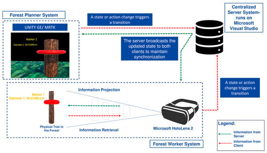
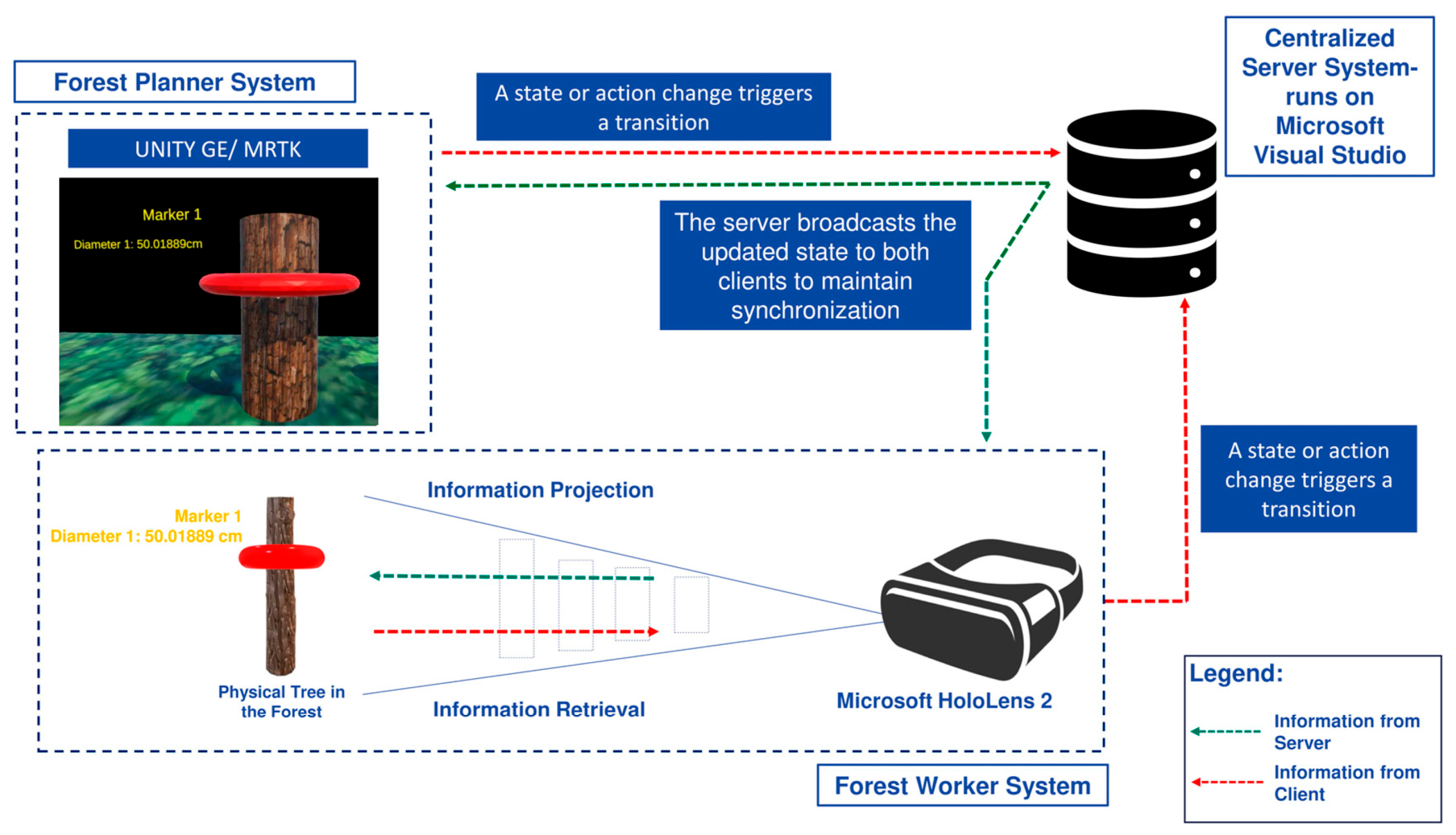
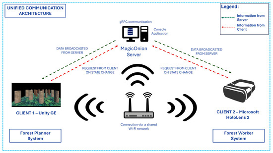
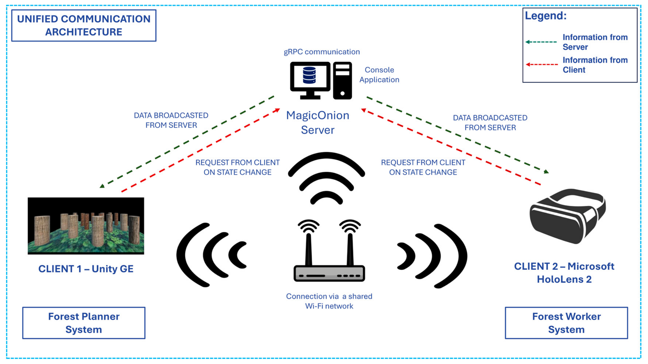
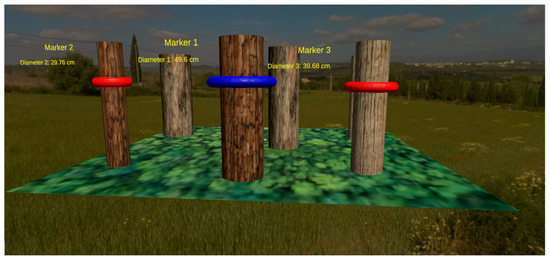
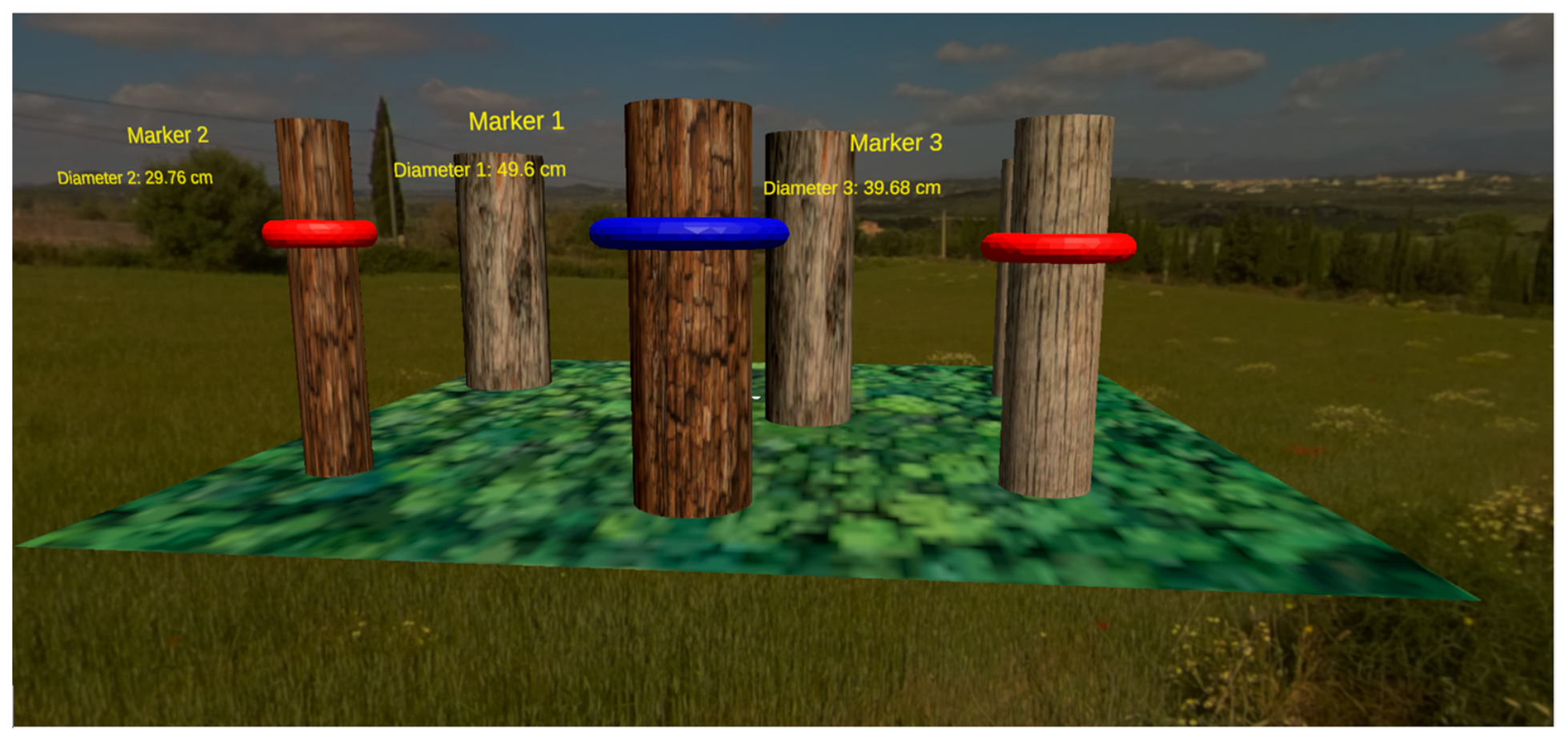
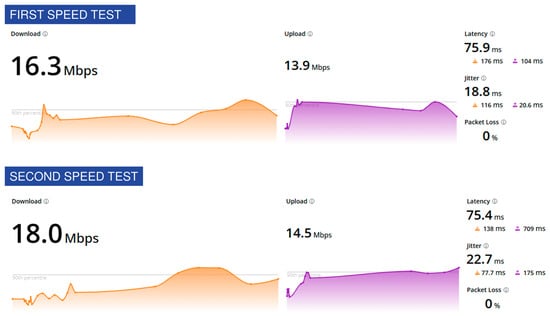
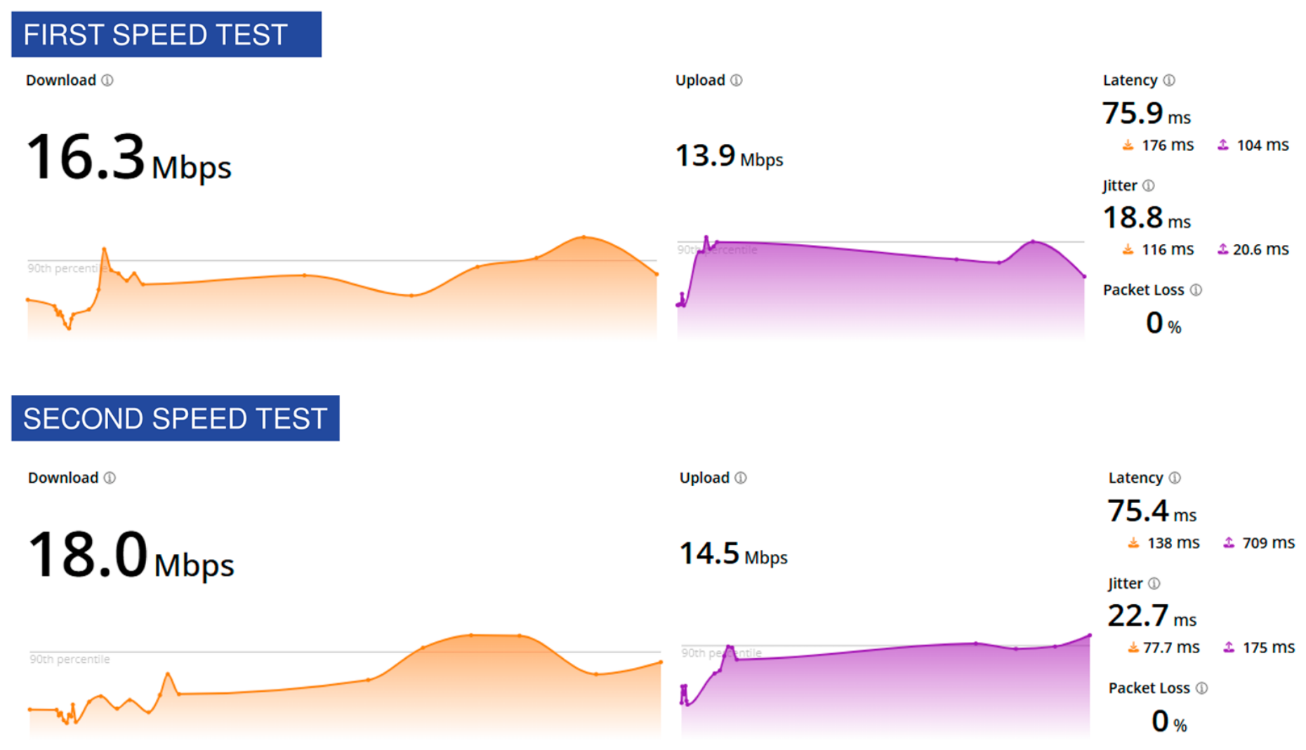
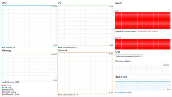
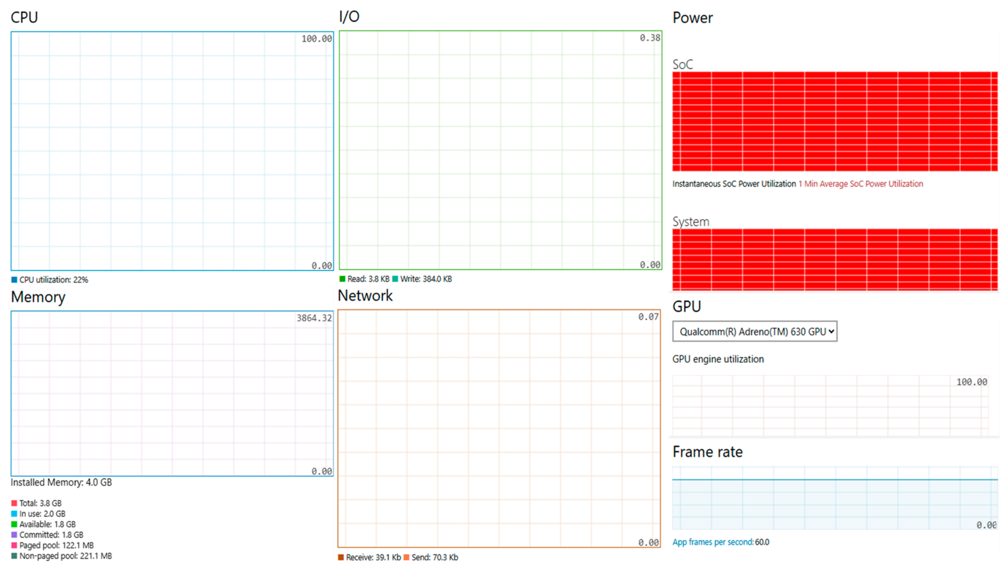
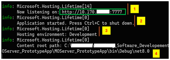
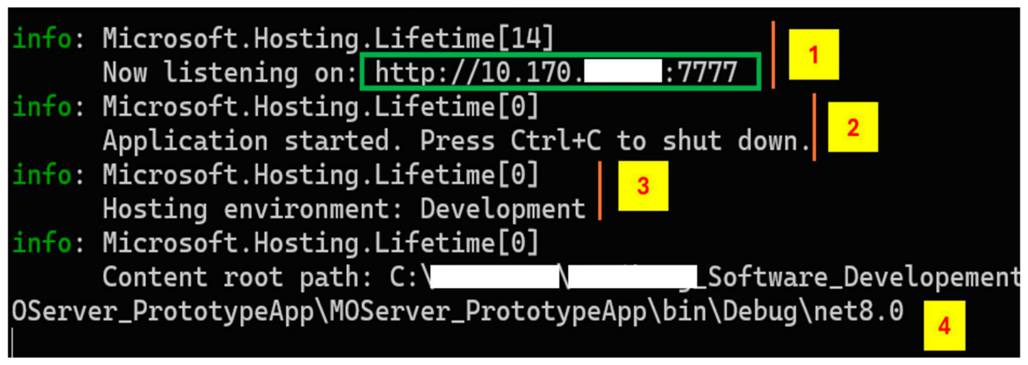
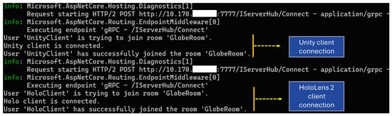
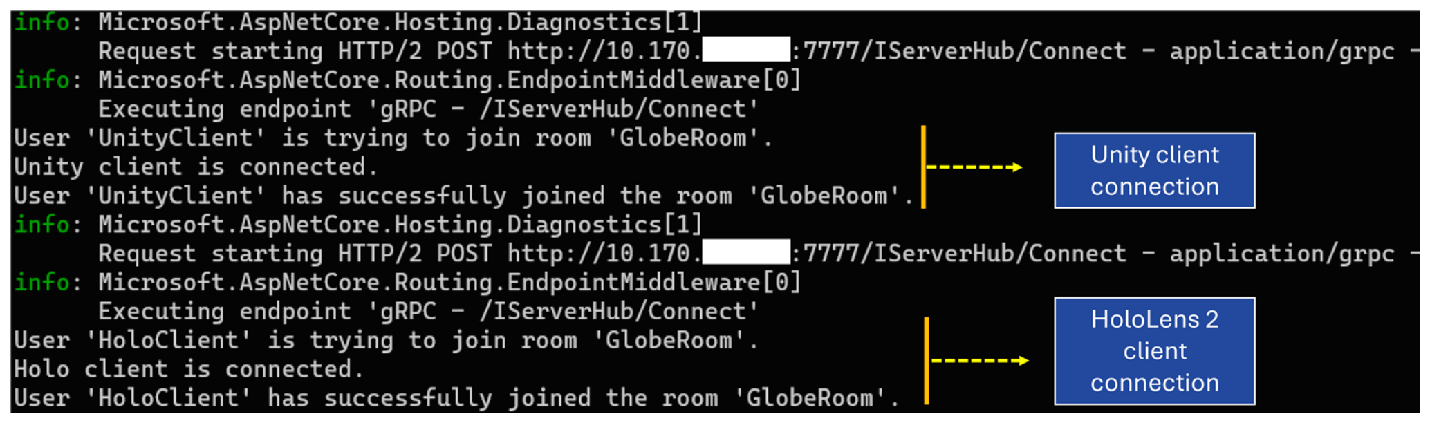
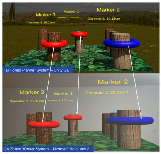
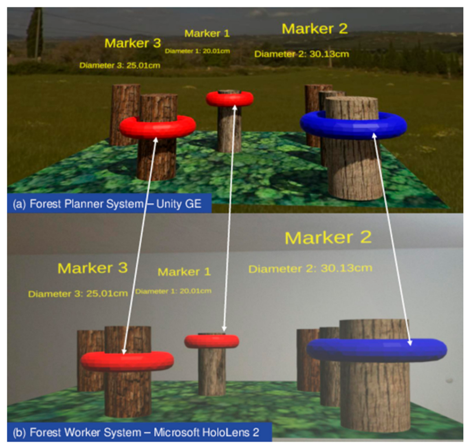
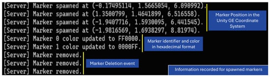
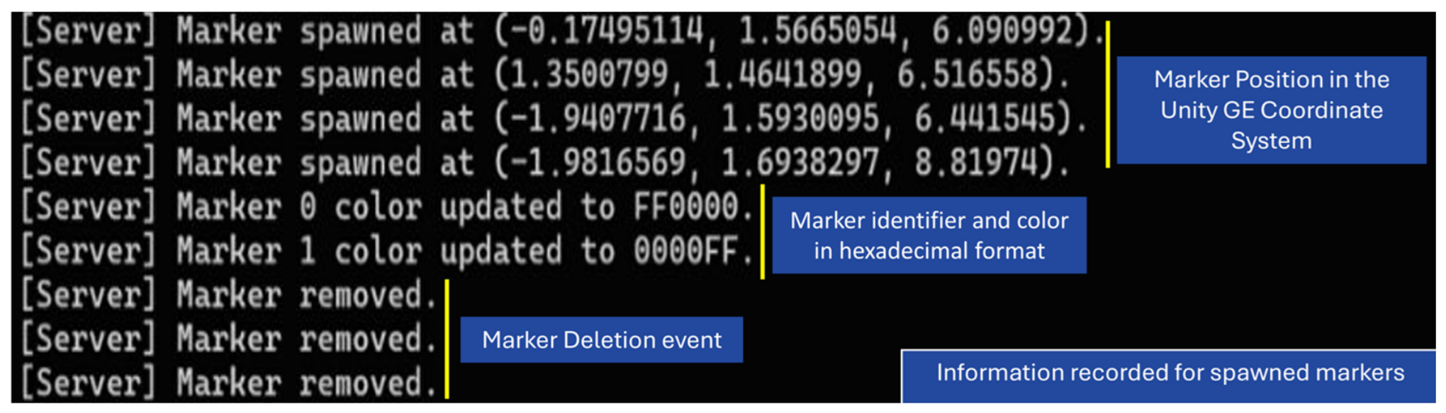
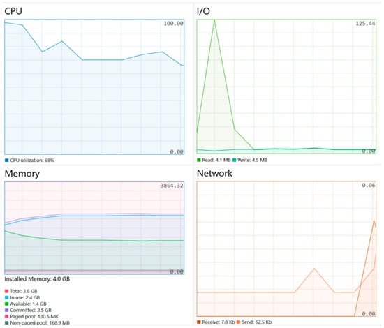
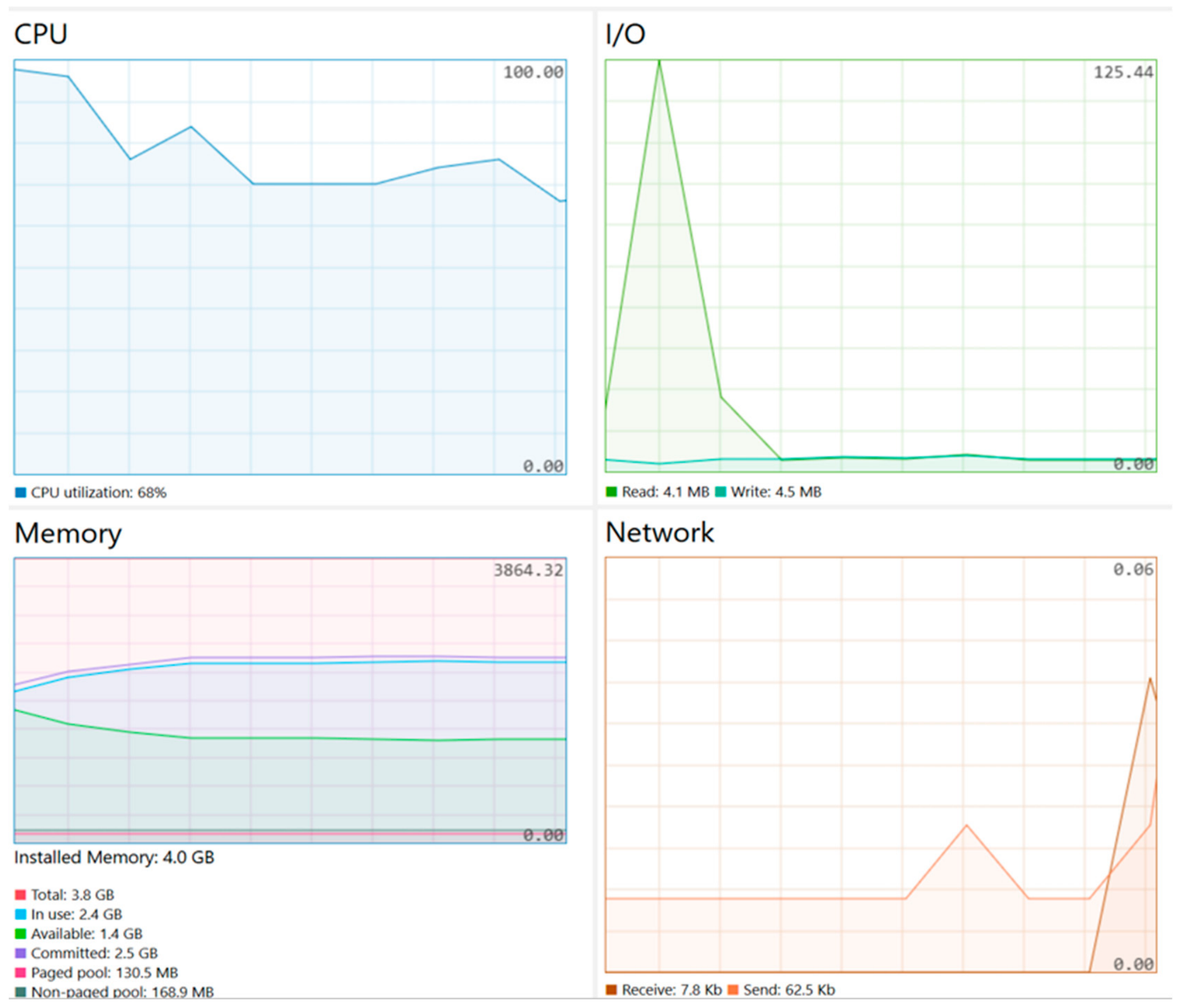

Disclaimer/Publisher’s Note: The statements, opinions and data contained in all publications are solely those of the individual author(s) and contributor(s) and not of MDPI and/or the editor(s). MDPI and/or the editor(s) disclaim responsibility for any injury to people or property resulting from any ideas, methods, instructions or products referred to in the content. |
© 2026 by the authors. Licensee MDPI, Basel, Switzerland. This article is an open access article distributed under the terms and conditions of the Creative Commons Attribution (CC BY) license.