


Abstract
Permanent magnet synchronous motors (PMSMs) are widely used in various fields due to their advantages. However, mechanical position sensor failures will cause various serious safety issues. High-frequency square-wave injection (HF-SWI) enables sensorless control of PMSMs at low speeds; yet, the fixed-frequency nature of conventional methods results in narrow current power spectral density (PSD), causing harsh noise and limiting the widespread application of sensorless control, especially in household appliances. To address this, this paper proposes a pseudo-random coding (PRC) injection strategy. First, a 23 PRC-injection method (23 PRC-IN) is introduced, which disrupts the signal periodicity by varying the injection frequency and amplitude, thereby significantly expanding the current PSD. To further suppress residual peaks in the 23 PRC-IN, an improved 2(3&1) PRC-IN method is developed. By optimizing the code transition logic, this approach can completely eliminate the sharp noise. Experiments on a 5.5 kW PMSM platform validate that the proposed methods effectively broaden the current PSD and reduce the noise without compromising position observation accuracy.
1. Introduction
Permanent magnet synchronous motors (PMSMs) are extensively employed in high-end manufacturing, electric vehicles, and aerospace systems due to their superior power density, high efficiency, and compact structure. Precise rotor position information, typically acquired via mechanical encoders, is crucial for achieving high-performance vector control. However, these sensors not only increase system cost and volume but also suffer from reliability issues under harsh conditions involving high temperatures, vibrations, and electromagnetic interference, leading to potential safety hazards. Sensorless control is a key technology to address this safety hazard [1,2,3,4,5,6,7,8]. Sensorless control technology, estimating rotor position from electrical signals, is indispensable for enhancing system robustness and reducing costs.
Among various sensorless schemes, low-speed operation remains a significant challenge due to the hard-to-measure back-electromotive force (EMF). To overcome this, high-frequency signal injection methods are widely adopted as they exploit the machine’s magnetic saliency rather than relying on back-EMF. While surface-mounted PMSMs (SPMSMs) inherently lack structural saliency, artificial saturation effects are utilized to create differential inductances between the d- and q-axes, enabling position observability [4,7]. Compared to sinusoidal injection, square-wave injection (SWI) offers higher dynamics and simpler signal extraction under limited switching frequencies [9,10], making it a preferred choice for low-speed SPMSM drives.
Nevertheless, the conventional fixed-frequency SWI (FF-SWI) method suffers from a critical drawback: the periodic injection generates concentrated harmonic power at discrete frequencies. This results in high power spectral density (PSD) peaks within the audible range (20 Hz–20 kHz), producing intense narrow-band acoustic noise and severe electromagnetic interference (EMI). To alleviate this noise, several strategies have been explored. Amplitude minimization via neural networks reduces noise but degrades the signal-to-noise ratio (SNR) and estimation robustness [11]. Low-frequency injection shifts noise out of the audible range but compromises dynamic performance under rapid load changes [12]. While sensorless schemes without extra injection can eliminate injection noise, they demand high-precision current sensors, increasing hardware costs [13,14].
Recently, spread-spectrum techniques using pseudo-random coding have emerged as a promising alternative [15,16,17]. Inspired by random PWM, these methods disrupt signal periodicity by randomly varying injection parameters. Dual-frequency hopping schemes have shown improvements over fixed-frequency injection (FF-IN) by flattening specific spectral lines [16,18]. Reference [17] adjusts the switching frequency randomly, so that the frequency of injecting high-frequency voltage can be adjusted randomly with the switching frequency, which can effectively reduce the audible noise caused by high-frequency current. However, frequent adjustment of switch frequency can result in additional switch losses, and irregular frequencies can generate unpredictable electromagnetic interference (EMI) and noise. Based on the reverse thinking, random triangular-wave current signals that should be HF responses of random phase-switching fixed frequency voltage injection are selected as the injected HF signals in [19]. The audible noise is reduced and the amplitude of HF responses is controllable. However, the injected frequency is limited by the bandwidth of current loop. A sinusoidal pulsating voltage with changeable frequency was used as injected voltage in [15,20]. However, since the injection frequency is much lower than the switching frequency, the band width of filters is restricted, leading to a decrease in the transient performance. Reference [21] considers the frequency and amplitude of the injected signal as a whole, and achieves pseudo-random signal injection by randomly adjusting the phase, which can ensure the required signal-to-noise ratio level for random signal injection while reducing the audible noise caused by high-frequency injected signals. However, frequent adjustment of the injection signal phase increases the computational burden of the control system. In [22], an adaptive PR signal injection scheme was presented to suppress the HF losses and acoustic noise through adaptively regulating the amplitude of the induced HF current. However, the corresponding signal selection was not presented, and there is still room for further improvement to reduce the acoustic noise to a larger degree. This coarse randomization fails to fully disperse the harmonic energy, leaving behind residual spectral peaks that still induce noticeable acoustic discomfort. Furthermore, the theoretical link between coding depth and spectral continuity remains underexplored [16].
To address these problems, this paper proposes a multi-level pseudo-random coding (PRC) injection strategy aimed at completely eradicating noise, which can effectively expand the current PSD, reduce and ultimately eliminate the harsh noise caused by high-frequency square-wave injection. The proposed strategy can broaden the wide application of sensorless control strategies based on high-frequency square-wave injection, especially in household appliances. The specific contributions are:
- (1)
- A 23-level pseudo-random coding injection (23 PRC-IN) method is proposed. By increasing the number of randomized states (frequency and amplitude), the harmonic energy is dispersed across a much wider band, significantly suppressing dominant peaks and expanding the current PSD compared to conventional high-frequency square-wave injection approaches.
- (2)
- An Improved 2(3&1) PRC-IN method is developed. By optimize the coding sequence, the inherent periodicity of the 23 PRC-IN is further disrupted, eliminating residual peaks and achieving a continuous, flat PSD profile. The proposed method effectively widens the current PSD and eliminates noise without affecting the accuracy of position observation, and can be widely applied in speed sensorless control of household appliances.
The remainder of this paper is organized as follows: Section 2 analyzes the mathematical model of SPMSM under saturation and reveals the mechanism of sharp noise generation in the FF-IN method. Section 3 details the 23 PRC-IN implementation and introduces the improved 2(3&1) PRC-IN method and its spectral optimization mechanism. Section 4 presents comparative experimental results, followed by the conclusion in Section 5.
2. Modeling and Introduction of Conventional FF-IN Method
2.1. Mathematical Model of PMSM
The mathematical model of the PMSM in the dq-axis coordinate is given as
where ud, uq, id, iq are the d-q axis stator voltage and current, respectively. Rs, Ld and Lq respectively represent stator resistance and d-q axis stator inductance. ψf is permanent magnet flux linkage and ωr is the rotor electric angular speed.
2.2. Control Principle of Conventional FF-IN Method
The FF-IN method generates saturated saliency by injecting a signal into the dr axis of a pre-set drqr axis system. At this time, the motor produces a corresponding high-frequency response current, which contains rotor angle information. By processing the response current, rotor position and angle information can be extracted and obtained. Since the frequency of the injected high-frequency voltage signal is several times the fundamental frequency of the motor, and the equivalent reactance and equivalent resistance of the motor under high-frequency conditions are very small, the equivalent resistance and reactance Rs, ωhfLdhf and ωhfLqhf at high-frequency can be neglected [16,17]. Therefore, (1) can be expressed as
where udhf and uqhf represent the dq-axis voltage components at high-frequency; Ldhf and Lqhf are the dq-axis inductances at high-frequency; idhf and iqhf are the high-frequency current responses.
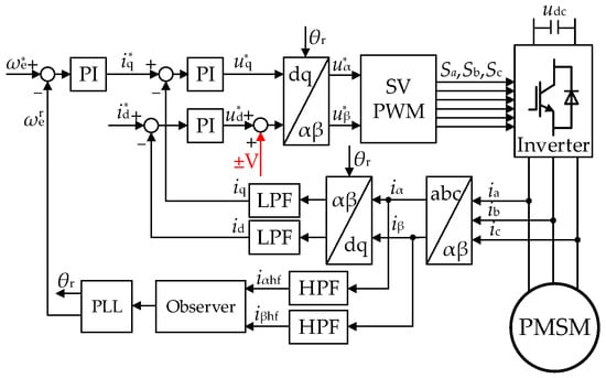
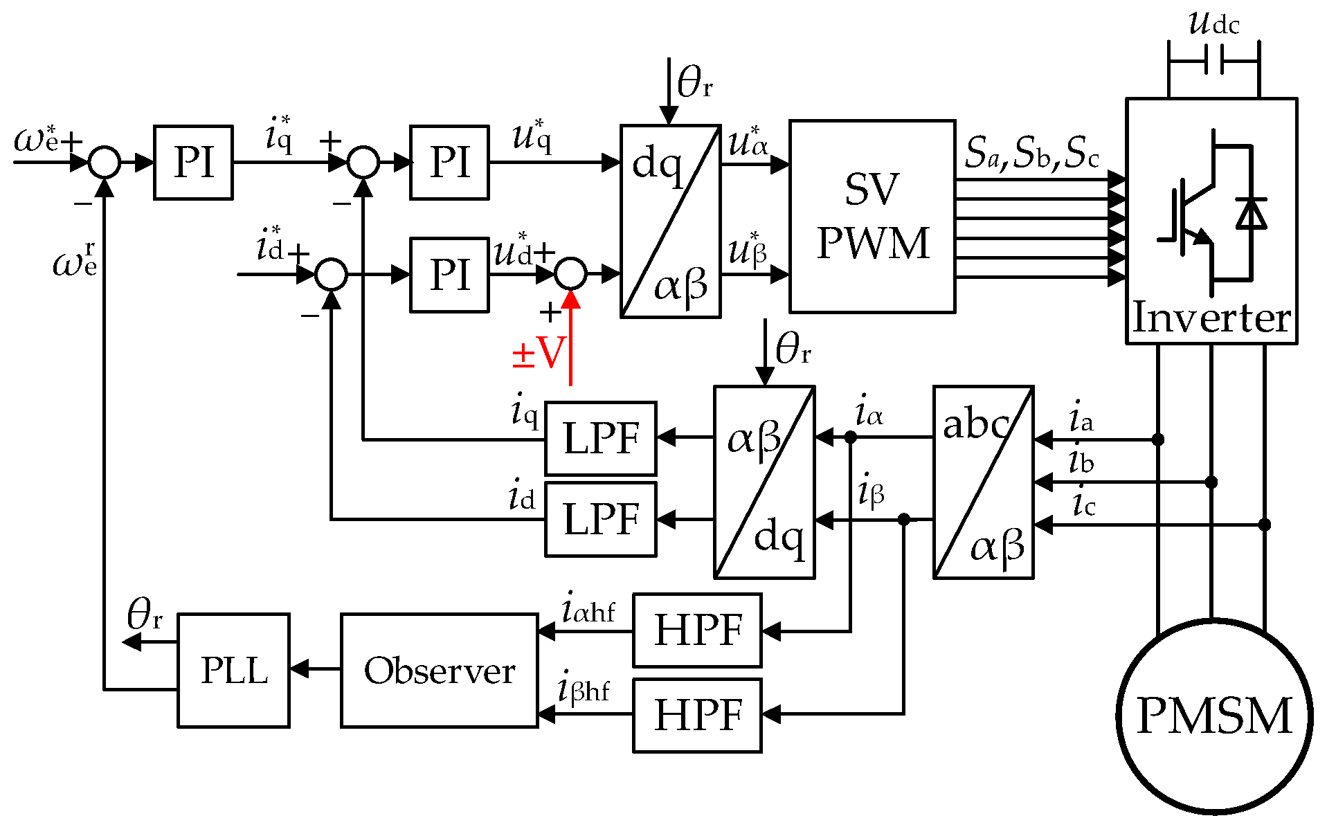
Let θ be the angle between the dq-axis and αβ-axis, and let the drqr-axis be the estimated dq-axis, with angle θr between the drqr-axis and the αβ-axis. The high-frequency signal will be injected into the control system through this virtual axis. The angle between the drqr-axis and the dq-axis is θe, and θe = θ − θr. Figure 1 is the system control block diagram based on the FF-IN method.
Figure 1.
Block diagram based on the FF-IN method.
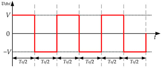
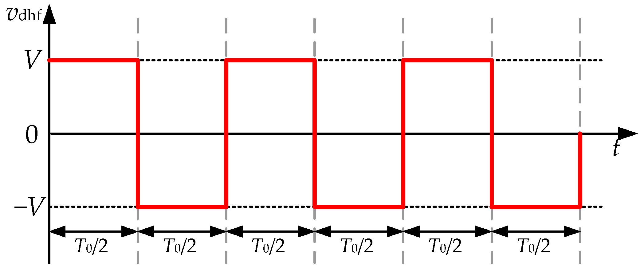
The FF-IN method does not have a coupling effect on the estimated q-axis torque, so the electromagnetic torque ripple is not significant during actual operation. Inject a high-frequency square-wave signal on the estimated d-axis, with its amplitude set to V. Figure 2 shows a schematic diagram of the FF-SWI signal. Select the high-frequency injection signal frequency as fh.
Figure 2.
Schematic diagram of injected FF square-wave signal.
The expression for the injected high-frequency voltage signal is represented in (3). n represents the sampling sequence number.
Simplify the high-frequency mathematical model,
where Ldqhf is a matrix composed of Ldhf and Lqhf,
where Δθ = θ − θr; L0 and L1 represent the mean inductance and the difference inductance, respectively. Substituting (3) into (4),
Perform an iPark transformation on (5) in the two-phase stationary coordinate. The ultimate goal of angle estimation is to track the actual angle in real-time; therefore, Δθ is sufficiently small, approximately equal to 0, then
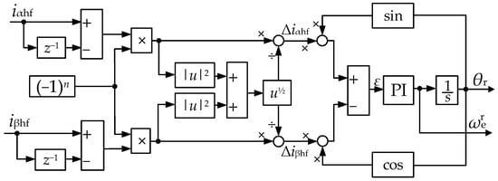
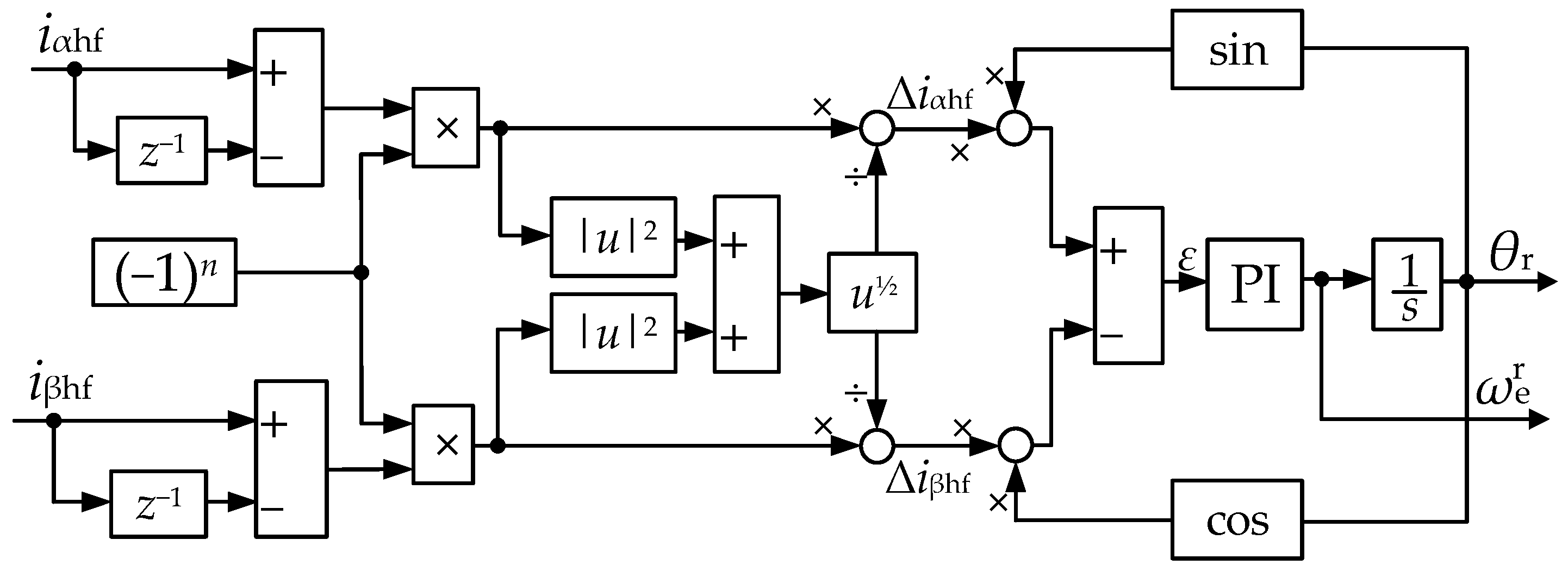
When injecting a high-frequency square-wave signal, the motor can be regarded as an equivalent inductance, and the current remains unchanged for the same period of time. It can be assumed that within the calculation period of PI control, the fundamental current remains almost unchanged, with only the high-frequency current changing [16,17,21]. Therefore, the response of the high-frequency current can be achieved simply by subtracting the current in the two sampling periods. The high-frequency response signal at this time is given by (7).
where Th represents the period of the injected high-frequency square-wave signal.
As can be seen from (7), the response of high-frequency current is influenced by the amplitude and period of the injected voltage. Therefore, normalization is necessary to ensure that changes in motor parameters and the amplitude of the high-frequency voltage signal injected into the system do not alter the parameters of the observer, allowing the observer to be applied widely. By tracking and processing this signal through a phase-locked loop (PLL), the estimated rotor position angle can be obtained, and the system’s speed value can be obtained through an integration process. Figure 3 is a block diagram of the position observer and PLL. As can be seen from Figure 3, when the motor runs stably, there is θr − θ ≈ 0. Therefore, there is
Figure 3.
Block diagram of position observer and PLL.
2.3. PSD Analysis of FF-IN Method
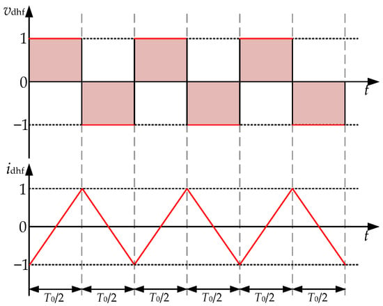
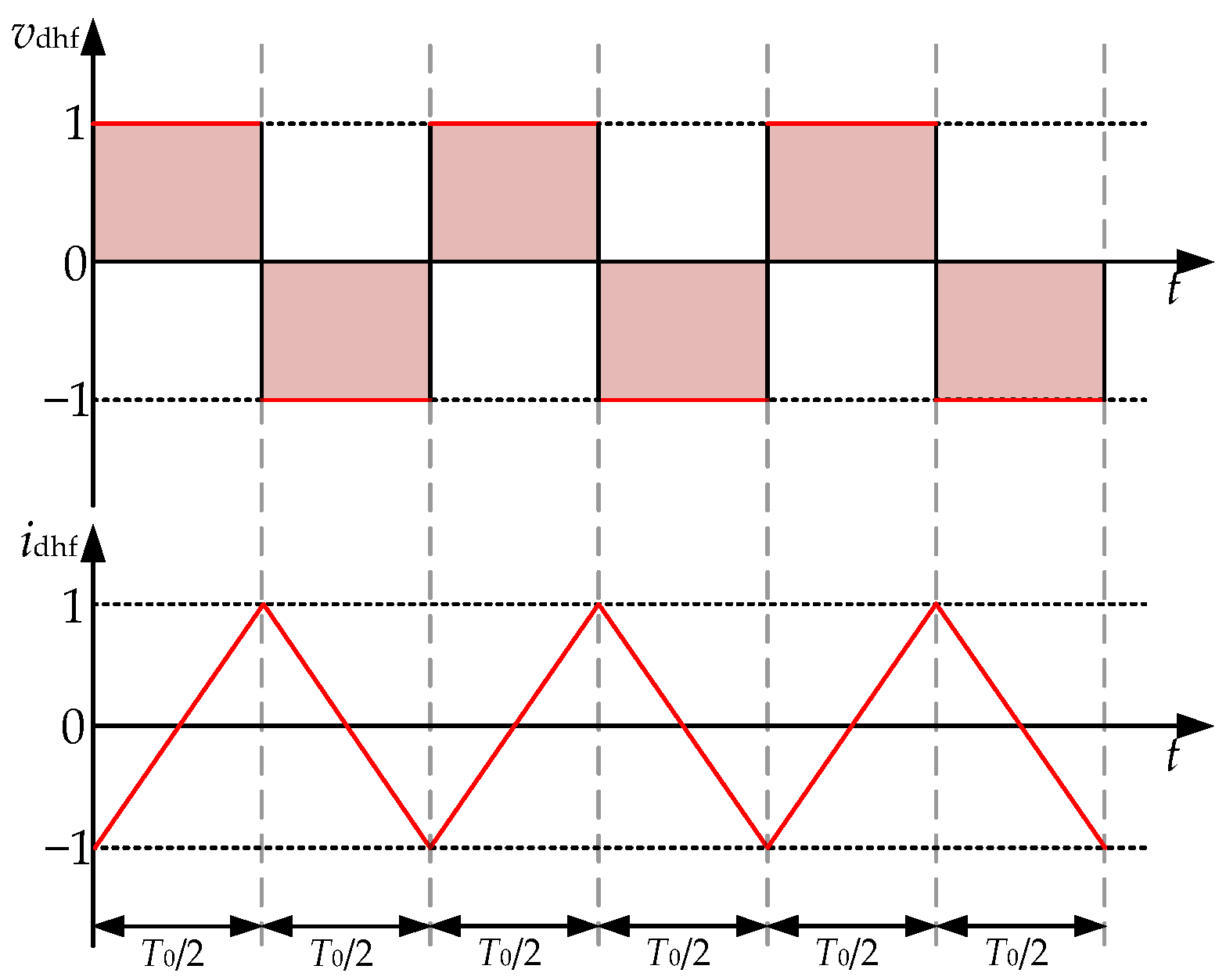
The PSD is a spectral analysis of the energy contained in a random signal per unit time and frequency band, serving as an effective tool for analyzing random signals. The injection frequency of the conventional fixed-frequency square-wave injection method remains unchanged during the control process. Figure 4 illustrates the high frequency voltage and current waveforms in fixed-frequency voltage injection.
Figure 4.
Injected voltage and induced current in fixed-frequency voltage injection.
To simplify the analysis, and since the objective of sensorless control is to make the estimated d-axis coincide with the actual d-axis, it is assumed that a fixed-frequency square-wave voltage is injected into the actual d-axis, and the induced current can be expressed as
This article discusses unit amplitude current. The PSD of a fixed-frequency current can be calculated as
where n = 0, 1, 2, 3, … is an integer, and ID1,D2(f) represents the Fourier transform of the current within one cycle.
As can be seen from (10), it only contains discrete harmonic components. Usually, in fixed-frequency voltage injection, D1 = D2 = T0/2, and (10) can be transformed into
By substituting f = N/T0 into (12),
From (13), it can be deduced that the frequency of the high-frequency current induced by the fixed-frequency injection signal is fixed. The current PSD contains discrete harmonics, which are concentrated on the injection signal and its odd multiples.
3. Sensorless Control Based on 2n PRC-IN Methods
3.1. 2n Sequence Pseudo-Random Signal Coding Principles
In the generation principle of 2n pseudo-random signal coding [23,24], it is first necessary to define a self-enclosing addition in a set of three elements: −1, 0, and 1.
Definition: there is a set, Z|z|<2 (where Z is an integer set), which is composed of integers with absolute value less than 2. There are three elements in Z|z|<2: −1, 0 and 1. It is stipulated that the following addition operation is true in Z|z|<2.
The sum of finite 1 equals 1,
The sum of finite −1 is equal to −1,
The sum of a finite 0 equals 0,
The essence of this provision is: the sum of any two elements in Z|z|<2 and the sum of any one element itself followed by a finite number are still included in Z|z|<2.
The addition also has the following properties.
1. The single operation of addition between 1, 0, −1 satisfies the commutative law and associative law of addition.
2. In a formula, if 1 or −1 is added twice or more, it must be added in order, and neither the commutative law nor the associative law holds.
3. The 0 in the set Z|z|<2 is not allowed to be split into the sum of the other two elements for further operation. For example, in 1 + 0 = 1, 0 cannot be split into 1 + (−1).
In order to distinguish it from ordinary arithmetic addition and modulo-2 addition, the sign “∪∩” is used to represent the closed addition rules in 3-element (−1, 0, 1) set. This method can be used to obtain 2n sequence pseudo-random coding.
Function
where i = 1, 2, …, n; k = 0, ±1, ±2, ±3…
When i = 1, (20) is obtained.
Obviously, this is a square-wave with amplitude A = 1 and period T2n = 21. It can be represented by encoding with two elements 1 and −1. Thus, the coding of function f1(t) can be recorded as {1, −1} (because the function fi(t) has periodicity, only one cycle code of function f1(t) is written out.).
When i = 2,
The square-wave with amplitude A = 1 and period T2n = 22 is obtained. The coding can be recorded as {1, 1, −1, −1}.
Both element 1 and −1 belong to the set Z|z|<2. The functions f1(t) and f2(t) are coded with one cycle of length f2(t) (that is, two cycles of f1(t)). Add them in the three-element set Z|z|<2, and can be recorded as
where fi(t) is (20). Continue with this addition and get
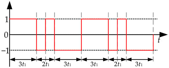
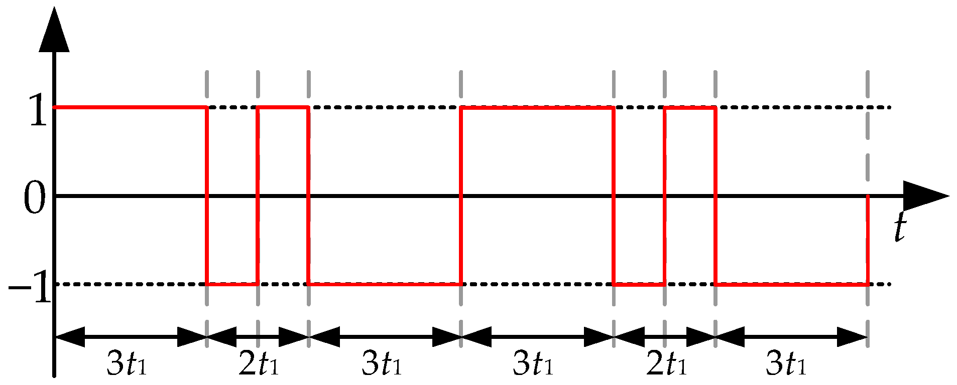
It is represented using a three-element encoding. When n = 3, the encoding is {1, 1, 1, −1, 1, −1, −1, −1}. The waveform of the 23 pseudo-random coding waveform is shown in Figure 5.
Figure 5.
23 PRC signal waveform.
3.2. Sensorless Control with 23 PRC-IN Method
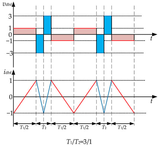
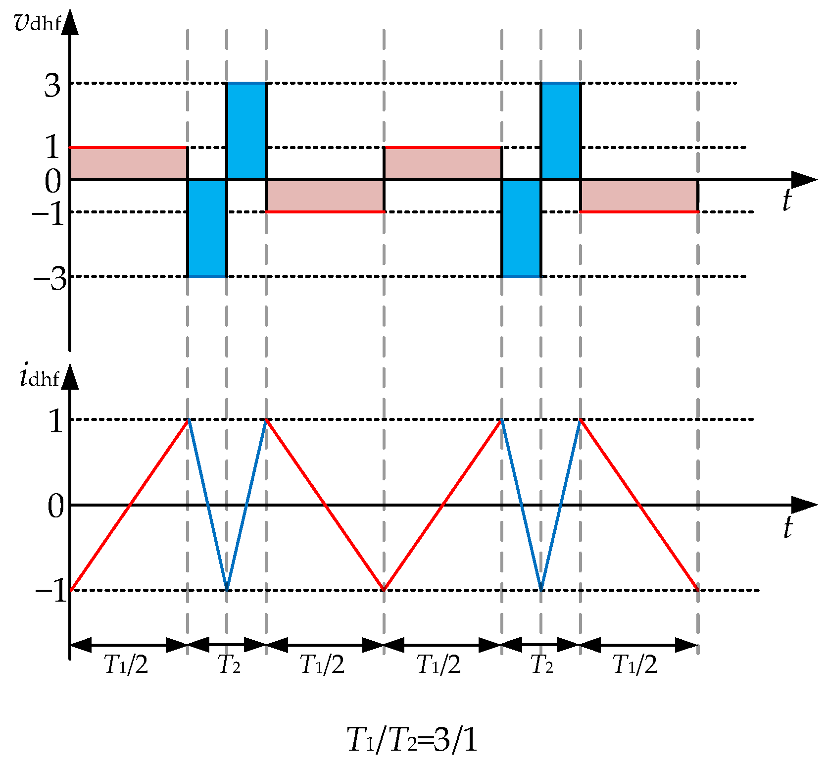
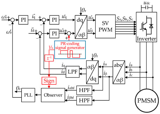
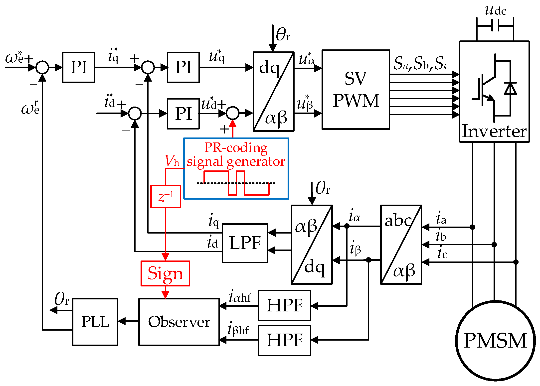
As shown in Figure 6, the 23 PRC-IN method is selected from two types of square-wave voltage signals with fixed frequency and fixed amplitude. Then, the 23 PRC square-wave voltage signal is injected into the estimated d-axis. The signal consists of a combination of two square waves with different frequencies. T1 and T2 represent the periods of the injected signal, with corresponding frequencies f1 and f2, respectively. The amplitudes of the square waves with the two frequencies should ensure that the amplitude of the generated response current is the same. The current is the integral of the injected voltage, thus achieving volt-second balance.
Figure 6.
Injection voltage and induced current of 23 PRC-IN method.
The unit area square-wave function is defined as
The unit amplitude sawtooth wave function is
In the 23 PRC-IN method, the injected voltage can be represented as
where tk represents the k-th cycle of the injected voltage, and Vh is the magnitude of the injected voltage. By injecting the voltage signal into the estimated d-axis, the induced current in the q-axis can be expressed as
The signal iqhf(t) fluctuates around zero, and its amplitude varies with the position error Δθ. When Δθ approaches zero, iqhf(t) is proportional to Δθ. Therefore, it contains equivalent position error information. By multiplying iqhf(t) with the demodulated signal φP, we can obtain the equivalent position error signal z.
The demodulated signal φP and the equivalent position error signal z can be expressed as
The equivalent position error can be derived through irqhf and the demodulated signal φP. Subsequently, the PLL is also employed to control the error z to zero, thereby estimating the rotor position. Figure 7 shows the block diagram of 23 PRC- IN method. The high-frequency current generated by the 23 PRC- IN method contains rotor position information, which is extracted by a high-pass filter and then used for position estimation. By using a PLL to control the position error to zero, the rotor position can be obtained.
Figure 7.
Block diagram of 23 PRC-IN method.
3.3. PSD Analysis of 23 PRC-IN Method
Figure 6 shows the voltage and induced current in the 23 PRC square-wave voltage injection method.
The induced current can be expressed as
In (31), IT1,T2(f) represents the Fourier transform of the current within one cycle, consisting of IT1/2,T2/2(f) and IT2/2,T1/2(f). T1/T2 = 3:1.
The current PSD result S(f) of (30) can be calculated as follows.
1. When E[ej2πfT] ≠ 1:
2. when E[ej2πfT] = 1:
where E[] denotes the mathematical expectation operator. The expression of PSD consists of two parts: the continuous spectrum (32) and the discrete spectrum (33). The spectral peaks caused by discrete harmonics indicate terrible noise. Therefore, the key issue in noise reduction is to eliminate the discrete part.
The current iT1,T2(t) is selected from two modes. For the 23 PRC-IN method, according to (33), discrete harmonics may exist at frequencies f that satisfy the following conditions.
where Prand = [p1 p2] represents the probability matrix, where p1 and p2 are the probability parameters of injection frequency. Let fg denote the root of (34).
When
if (34) holds, then
is satisfied, and both fgT1 and fgT2 are integers, and fg is a common multiple of fg1 and fg2.
The relationship between fg1 and fg2 is
where x and y are the numerator and denominator of an irreducible fraction, respectively. The least common multiple (LCM) of fg1 and fg2 can be expressed as fg1y = fg2x = fg12. Therefore, (34) holds when f is an integer multiple of fg12, that is, f = Nfg12. Here, N is an integer. When N is even or odd, the result will be different. The roots of (34) should be found so that (37) is an integer.
In the 23 PRC-IN method, f1/f2 = 1/3, that is, x = 1 and y = 3, so x + y = 4 is an even number. According to (37), as long as N is an integer, N(x + y)/2 is an integer, and (34) holds. At this time, the root of (34) is f = Nfg12(N = 1, 2, 3, …). By substituting the root into (30),
Therefore, in the 23 PRC-IN method, discrete harmonics will only appear at odd multiples of the least common multiple of two frequencies. Compared to conventional fixed-frequency square waves, it can suppress some discrete harmonics and reduce noise. However, there are still discrete harmonics at odd multiples of the least common multiple of two frequencies, so further improvement and optimization of the 23 PRC-IN method are needed.
3.4. Sensorless Control with 2(3&1) PRC-IN Method and PSD Analysis
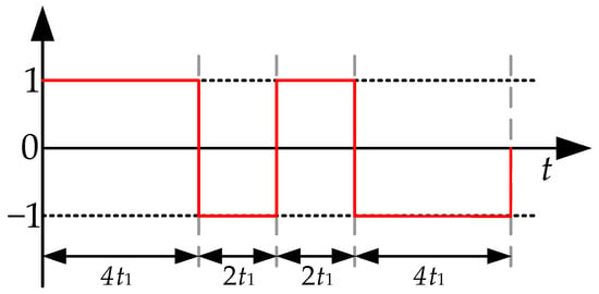
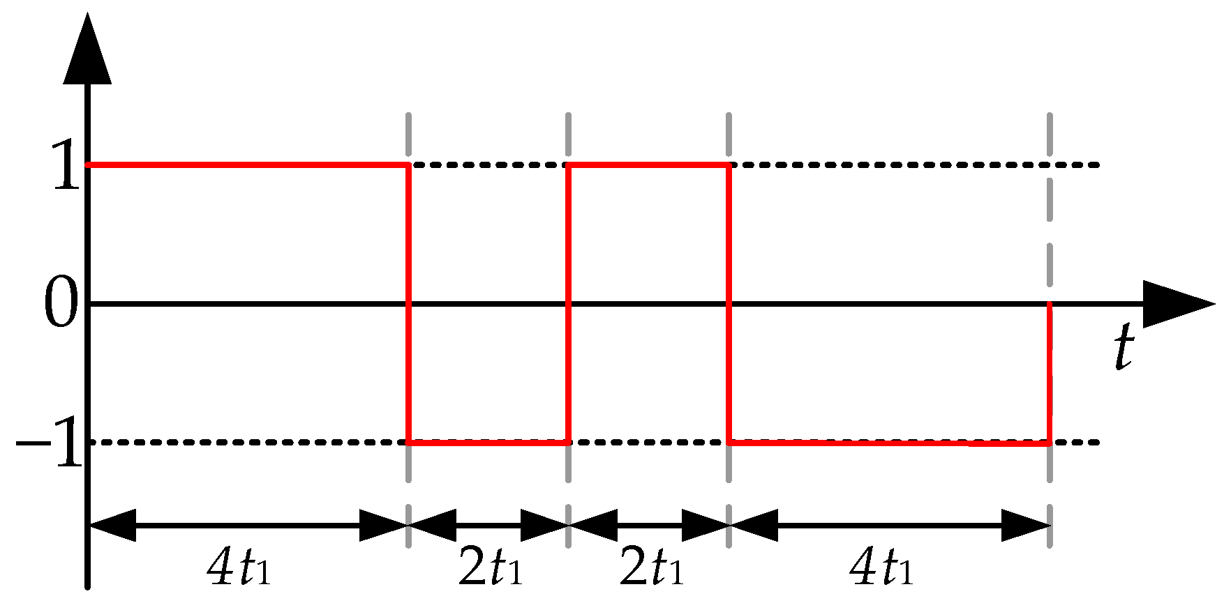
The 23 PRC is {1, 1, 1, −1, 1, −1, −1, −1}, which is equivalent to a combination of a square-wave with amplitude of 1 and frequency of f and a square-wave with amplitude of 3 and frequency of 3f. Since both x and y are odd, there will be discrete harmonics of odd multiples of the least common multiple of the two frequencies.
Therefore, the 23 pseudo-random code is improved by extending it at each amplitude change, changing the pseudo-random code to {1, 1, 1, 1, −1, −1, 1, 1, −1, −1, −1, −1}, denoted as 2(3&1) pseudo-random code. The waveform of the 2(3&1) pseudo-random coding waveform is shown in Figure 8.
Figure 8.
2(3&1) PRC signal waveform.
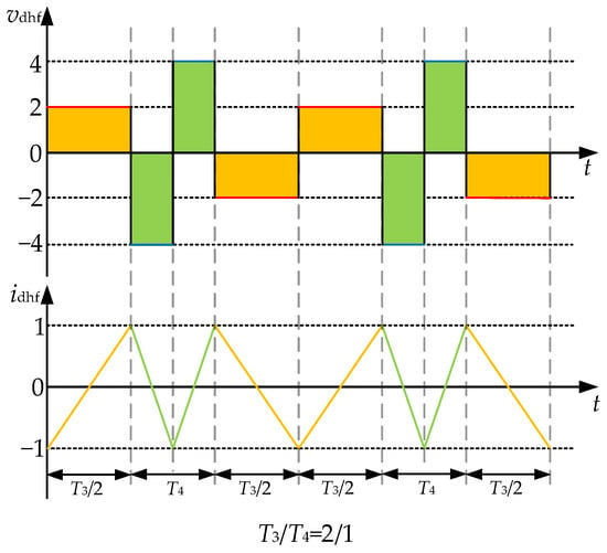
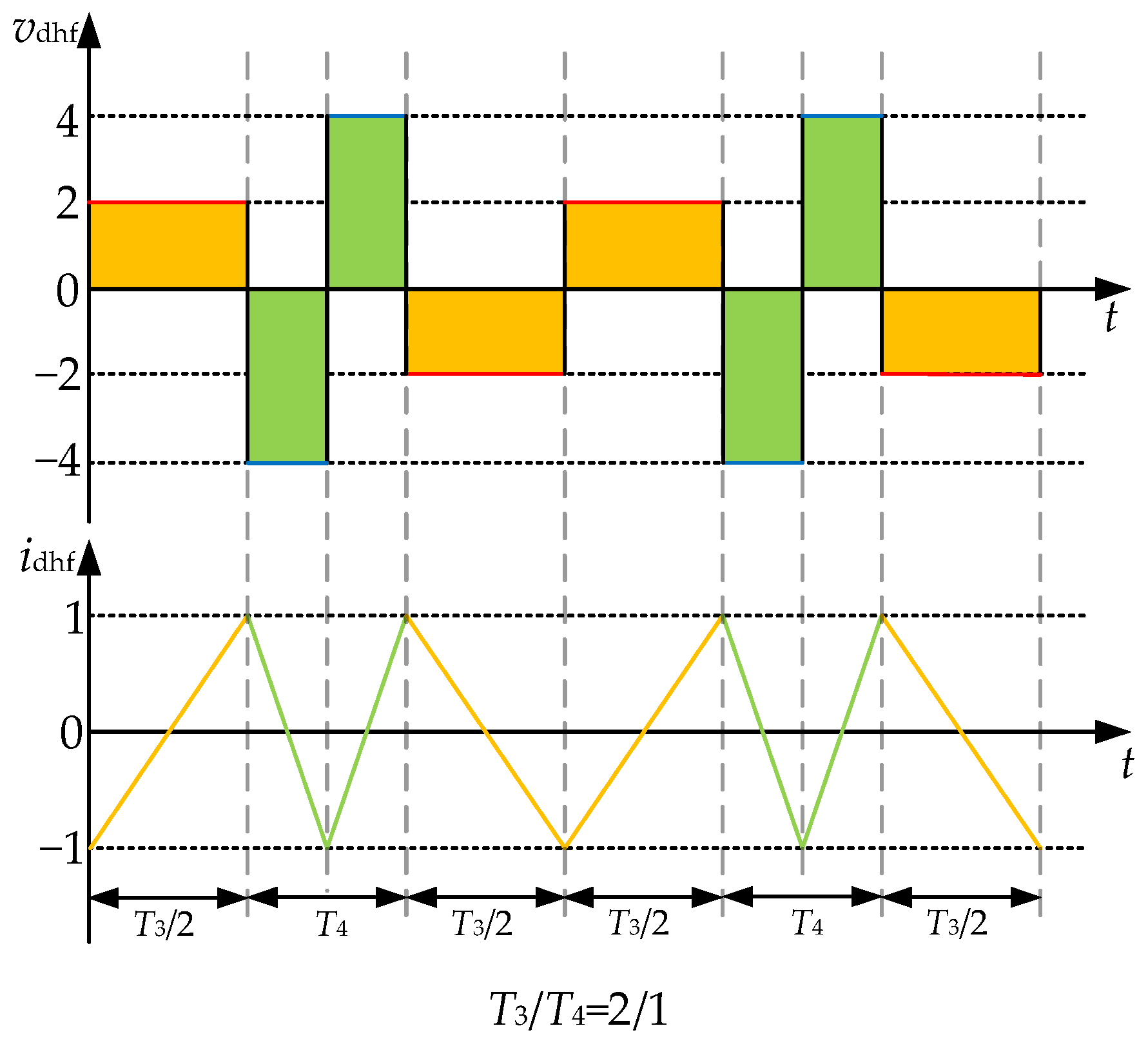
Figure 9 shows the voltage and induced current in the 2(3&1) pseudo-random high-frequency square-wave voltage injection method.
Figure 9.
Injection voltage and response current in 2(3&1) PRC-IN method.
IT3,T4(f) is the Fourier transform of the response current over one period, consisting of IT3/2,T4/2(f) and IT4/2,T3/2(f). T3/T4 = 2:1. IT3,T4(f) has the same form as IT1,T2(f).
From Figure 9, it can be concluded that the 2(3&1) pseudo-random coding square-wave is equivalent to a combination of a square-wave with an amplitude of 1 and a frequency of f, and a square-wave with an amplitude of 2 and a frequency of 2f. That is, x = 1 and y = 2, so x + y = 3 is an odd.
According to (37), only when N is even, N(x + y)/2 is an integer, and (41) holds. At this time, f = Nfg12 (N = 2, 4, 6, …) is the root of (34).
According to (38), if N is even, we can obtain both
In addition, E[|I(Nfg12)|] = 0 can be obtained according to (39). Therefore, in this case, discrete harmonics do not occur, and spectral peaks do not appear either, allowing for complete suppression of discrete harmonic peaks.
4. Experimental
4.1. Experimental Platform
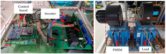
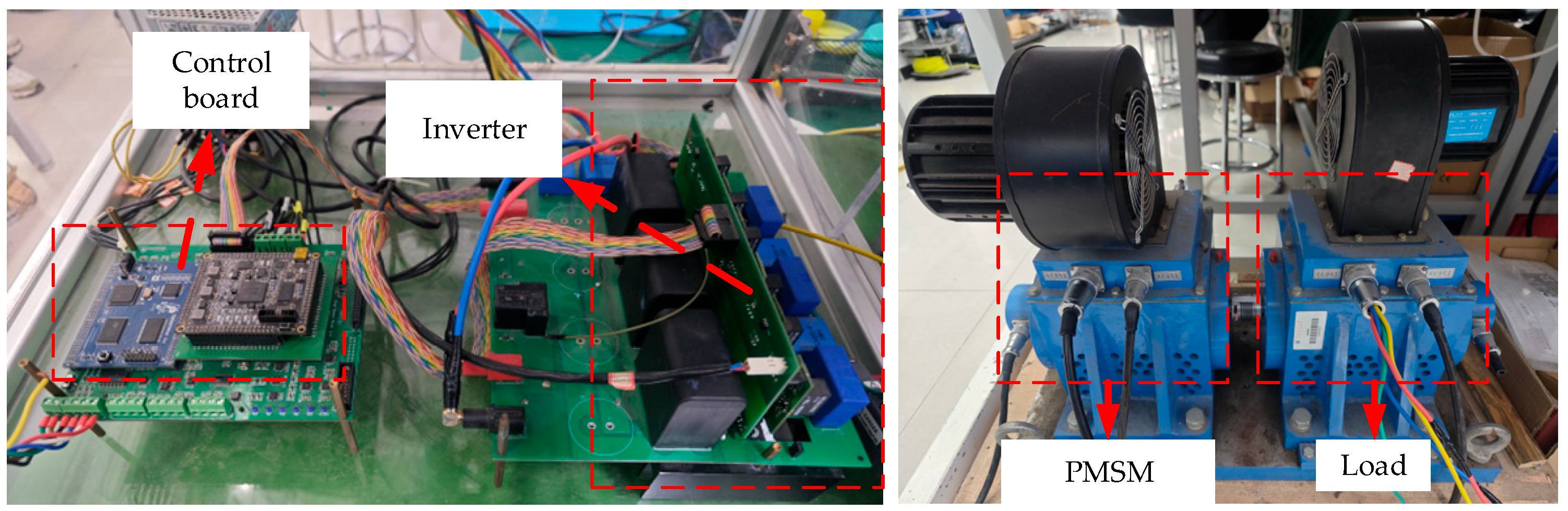
In this section, the proposed control algorithm and the conventional algorithm are compared experimentally. The experimental platform is illustrated in Figure 10, consisting of the HSPMSM and load. A floating-point TMS320F28346 DSP and XC3S400 FPGA are employed as the digital controller, and the sampling period of the control system is set as 50 μs (20 kHz). The key control parameters and specifications of the experimental are shown in Appendix A Table A1. Table 1 shows the parameters of PMSM. The torque waveforms in this paper are calculated in real-time by sampling the stator current of HSPMSM. To verify accuracy of the 23 pseudo-random coding square-wave injection method for estimating rotor position, the experimental motor was equipped with a resolver. The rotor position obtained by the resolver are only used to compare with the estimated rotor position.
Figure 10.
Photos of the experimental platform.
Table 1.
PMSM parameters.
4.2. Experimental Results
In the experimental section, three sensorless control operation tests were compared under a rated load of 300 r/min, including one test using fixed-frequency square-wave signal injection and two tests using pseudo-random square-wave signal injection. The experimental results demonstrate that rotor position information can be extracted not only using fixed-frequency current but also using the random current generated by pseudo-random square-wave signal injection.
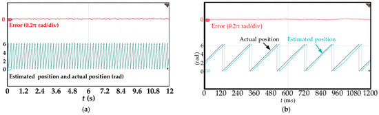
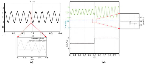
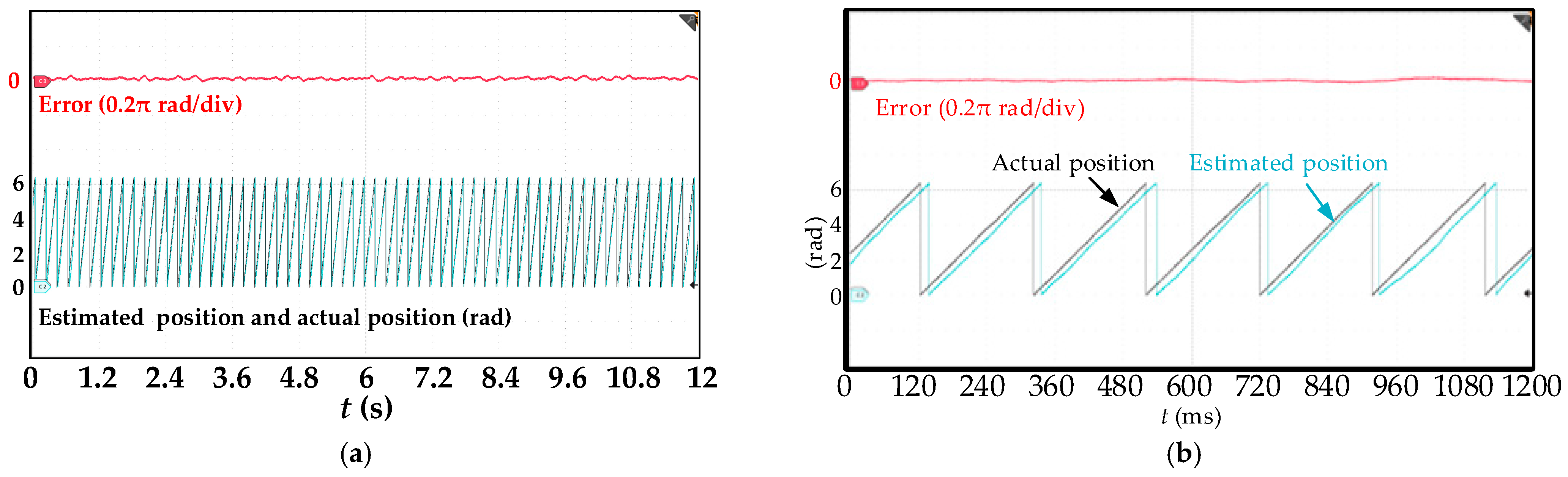
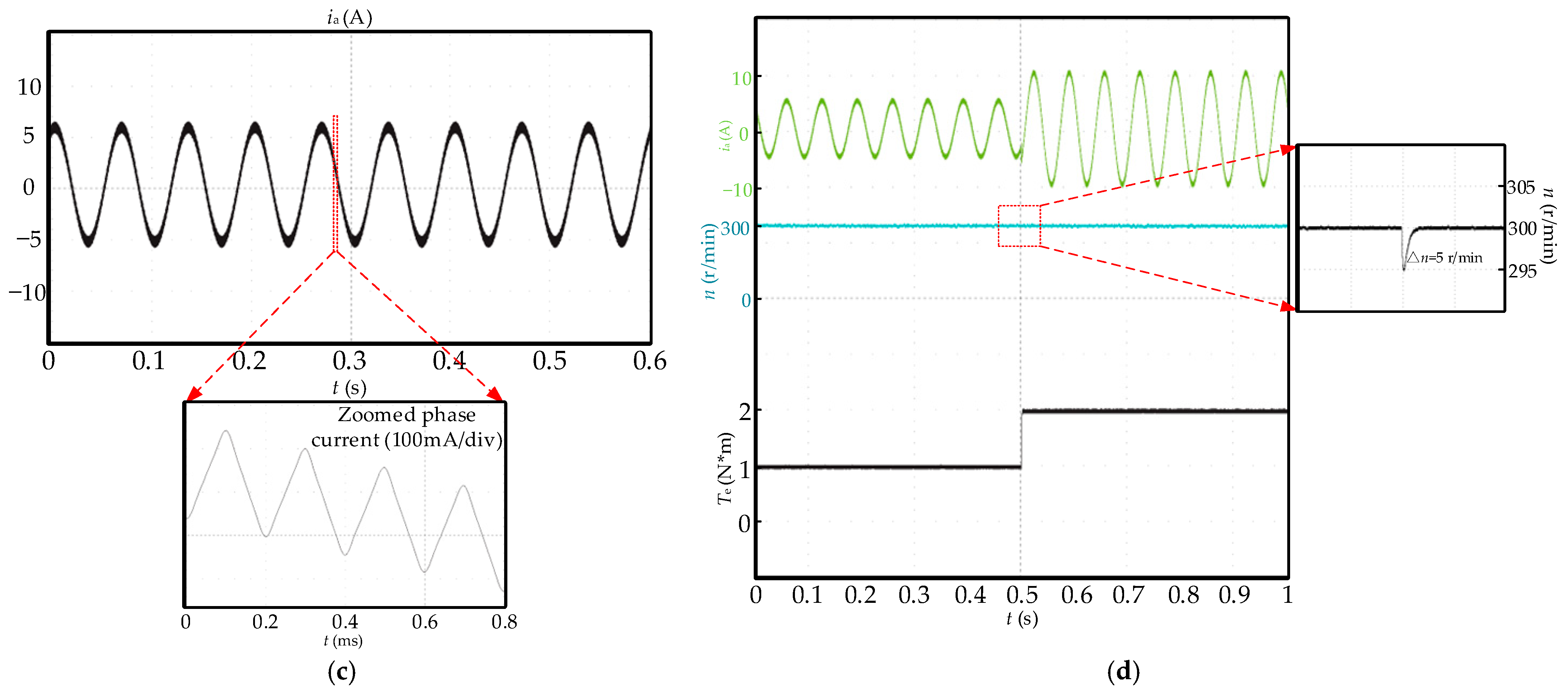
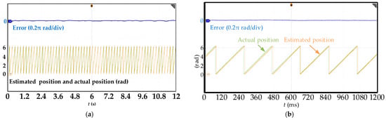
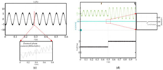
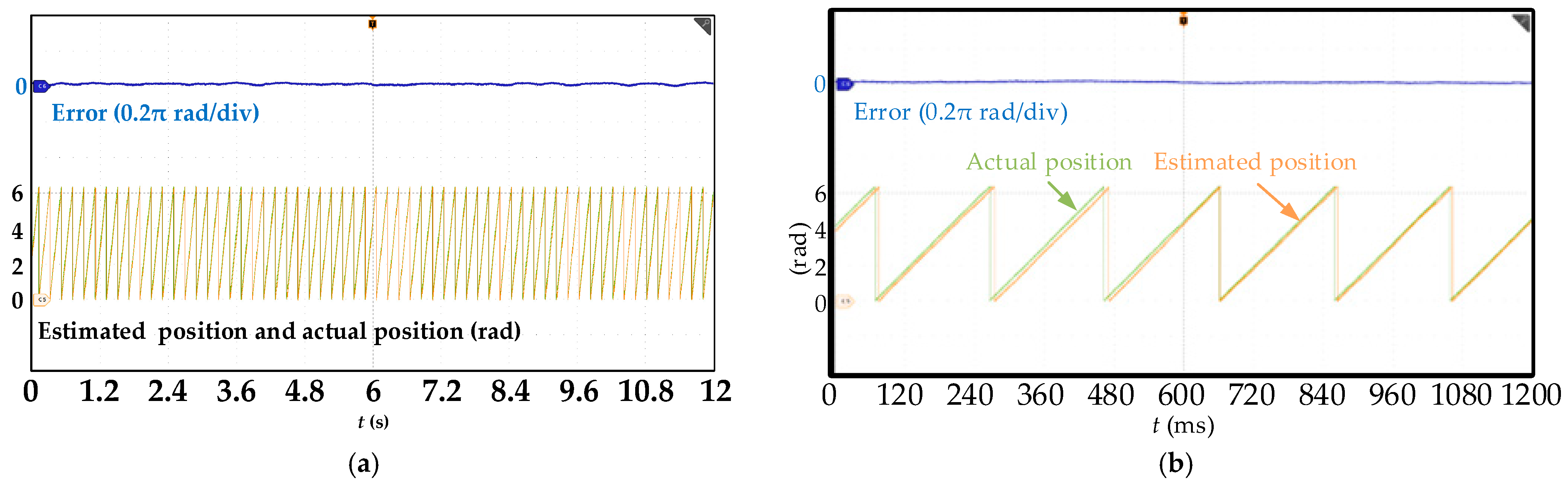
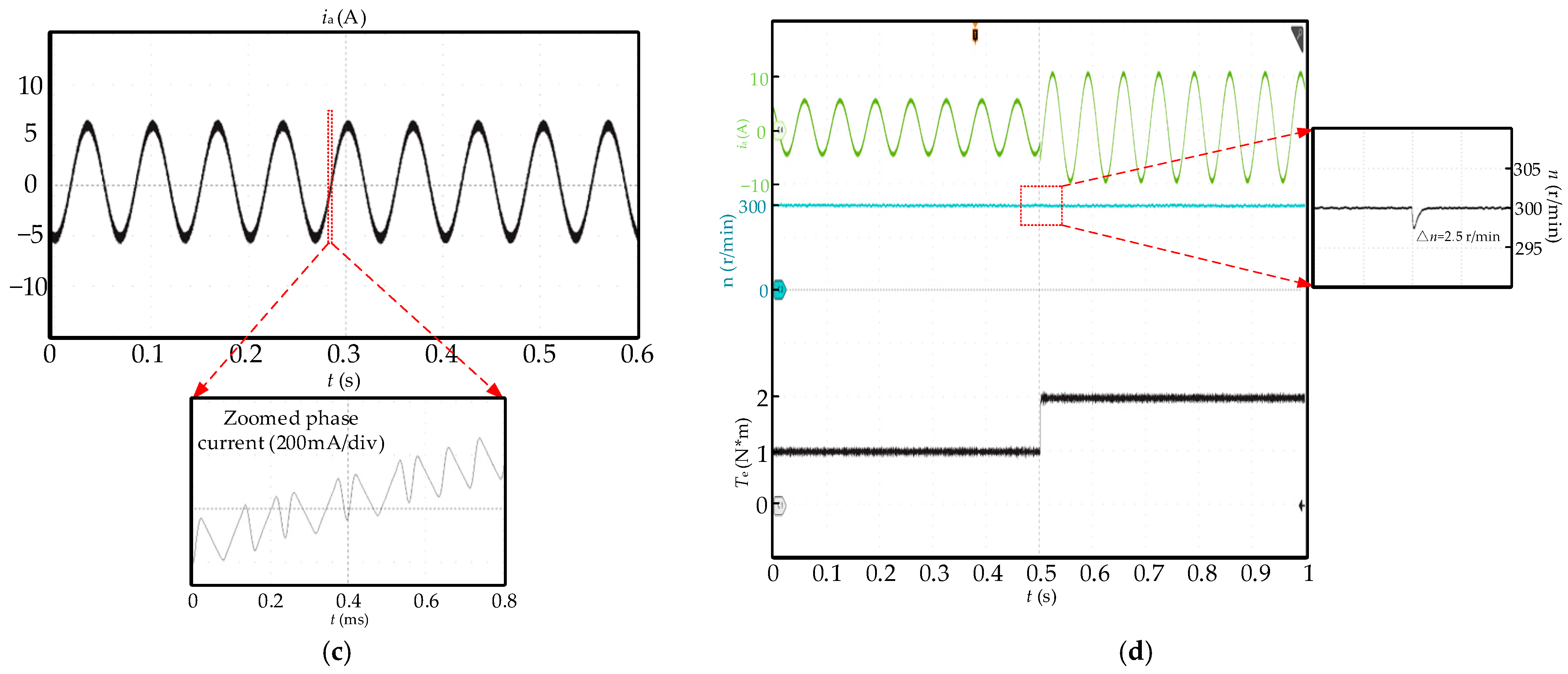
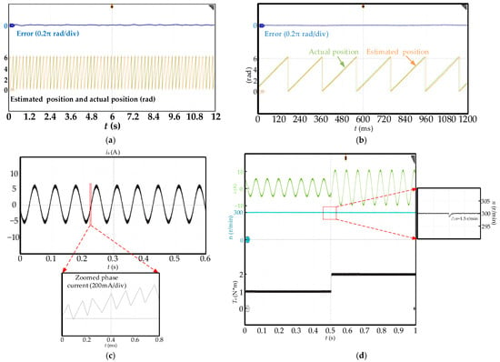
Figure 11 shows the waveform diagram under sensorless control using the conventional FF-IN method. The amplitude and frequency of the injected fixed frequency voltage are 40 V/5 kHz. As can be seen from Figure 11, the estimated rotor angle can track the actual rotor position, achieving sensorless speed control. At this time, the stator current will superimpose the high-frequency current harmonics generated by the injected high-frequency square-wave. As shown in Figure 11a, the difference between the estimated rotor angle and the actual rotor angle fluctuates significantly, with the maximum difference reaching 0.05π rad. As shown in Figure 11b, the estimated rotor angle can track the actual rotor angle, but it is far from being smooth and linearly increasing like the actual value, resulting in large errors and severe fluctuations between the estimated and actual values. Figure 11c shows the stator current and its local detailed waveform. It can be seen that the FF-IN method introduces a fixed frequency triangular waveform current in the stator current sine wave, thus generating high-frequency noise, which affects the widespread application of sensorless technology. Figure 11d shows the waveforms of stator current, speed, and torque under the load increases from 1 N*m to 2 N*m in FF-IN method, indicating that the motor speed is less affected by load changes.
Figure 11.
Waveforms under FF-IN method. (a) Actual angle, estimated angle and error; (b) enlarged angle and error; (c) stator current; (d) current, speed, and torque under load variation.
The probability parameters in 23 PRC-IN method and 2(3&1) PRC-IN method are set as Prand = [0.5 0.5]. Figure 12 depicts the waveform diagram under sensorless control using the 23 PRC-IN method. The amplitude and frequency of the injected pseudo-random coding square-wave voltage are equivalent to (40/3 V, 10/3 kHz) and (40 V, 10 kHz), respectively. As can be seen from Figure 12, the estimated rotor angle can also track the actual rotor position, achieving sensorless speed control. At this time, the stator current will superimpose the high-frequency current harmonics generated by the injected pseudo-random coding square-wave.
Figure 12.
Waveforms under 23 PRC-IN method. (a) Actual angle, estimated angle and error; (b) enlarged angle and error; (c) stator current; (d) current, speed, and torque under load variation.
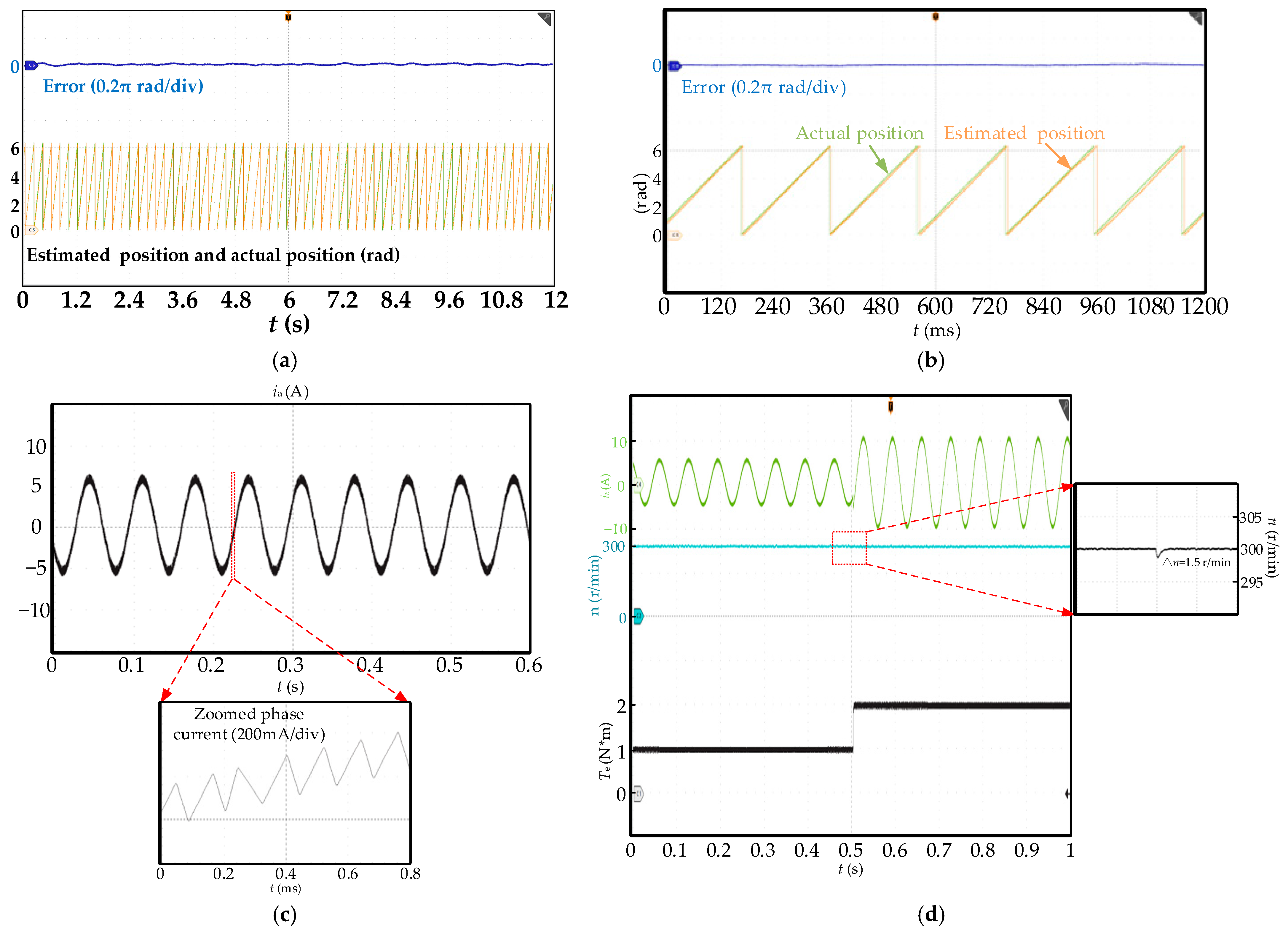
As shown in Figure 12a, compared to the FF-IN method, the difference between the estimated rotor angle and the actual rotor angle using the 23 PRC-IN method is significantly reduced, with significantly reduced fluctuations. The maximum difference only reaches 0.03π rad, making it a better alternative to the actual rotor angle and improving the reliability of sensorless speed control. As shown in Figure 12b, compared to the FF-IN method, the estimated value using the 23 PRC-IN method can better track the actual value, increase more smoothly and linearly, and be closer to the linear increase process of the actual value. At the same time, the error fluctuation between the estimated value and the actual value is also significantly reduced. Figure 12c shows the stator current and its local detailed waveform. It can be seen that the 23 PRC-IN method introduces a triangular waveform current with a 23 PRC frequency into the stator current sine wave, which can eliminate some high-frequency noise and reduce noise pollution. Figure 12d shows the waveforms of stator current, speed, and torque under the load increases from 1 N*m to 2 N*m in 23 PRC-IN method, indicating that the motor speed is less affected by load changes. Although the torque fluctuation has increased compared to the conventional FF-IN method, it is still within an acceptable range.
Figure 13 depicts the waveform diagrams under sensorless control using the 2(3&1) PRC-IN method. The amplitude and frequency of the injected pseudo-randomly coded square-wave voltage are equivalent to (20 V, 2.5 kHz) and (40 V, 5 kHz), respectively. As can be seen from Figure 13, the estimated rotor angle can also track the actual rotor position, achieving sensorless speed control. At this time, the stator current will superimpose the high-frequency current harmonics generated by the injected 2(3&1) PRC square-wave.
Figure 13.
Waveforms under 2(3&1) PRC-IN method. (a) Actual angle, estimated angle and error; (b) enlarged angle and error; (c) stator current; (d) current, speed, and torque under load variation.
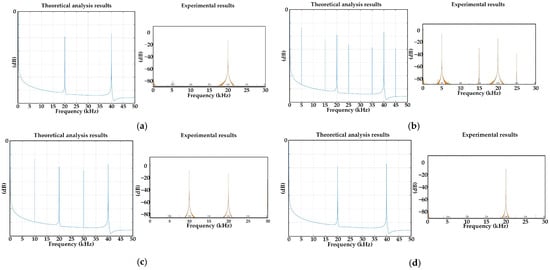
As shown in Figure 13a, compared to the FF-IN method and the 23 PRC-IN method, the difference between the estimated rotor angle and the actual rotor angle using the 2(3&1) PRC-IN method is significantly reduced, and the fluctuation is significantly reduced. The maximum difference using the 2(3&1) PRC-IN method is only 0.02π rad, which can better replace the actual rotor angle and improve the reliability of sensorless speed control. As shown in Figure 13b, compared to the FF-IN method, the estimated value using the 2(3&1) PRC-IN method can also better track the actual value, and it can increase more smoothly and linearly, closer to the linear increase in the actual value. At the same time, the error fluctuation between the estimated value and the actual value is also significantly reduced. Figure 13c shows the stator current and its local detailed waveform. It can be seen that the 2(3&1) PRC-IN method introduces a triangular waveform current with a 2(3&1) PRC frequency into the stator current sine wave, which can completely eliminate high-frequency noise and expand the application scope of sensorless speed control. Figure 13d shows the waveforms of stator current, speed, and torque under the load increases from 1 N*m to 2 N*m in 2(3&1) PRC-IN method, indicating that the motor speed is less affected by load changes. Although the torque fluctuation has increased compared to the conventional FF-IN method, it is still within an acceptable range.
From Figure 11d, Figure 12d and Figure 13d, it can be seen that under the condition of load changes, both the conventional FF-IN method, the 23 PRC-IN method and 2(3&1) PRC-IN method can quickly follow the given speed, but there will be a sudden drop in speed. When using the FF-IN method, the speed drops the most, reaching around 5 r/min, while the proposed 2(3&1) PRC-IN method has the smallest speed drop, around 1.5 r/min. The speed decrease in the proposed 23 PRC-IN method is slightly alleviated compared to FF-IN, at 2.5 r/min, but still greater than the speed decrease value of the 2(3&1) PRC-IN method. It can be seen that the proposed 2(3&1) PRC-IN method is minimally affected by load changes and has the strongest robustness. In addition, the steady-state errors of the three methods did not deteriorate under heavy load conditions. Therefore, it can be concluded that the 23 PRC-IN and 2(3&1) PRC-IN methods proposed in this paper can have better angle tracking capability while maintaining good robustness.
Table 2 shows the maximum error and RMS of angle estimation error for three HF-SWI methods under steady-state. From Table 2, it can be seen that the steady-state maximum error and RMS of the conventional FF-IN method are, respectively, 0.05π rad and 0.11 rad, which are greater than the 0.03π rad and 0.06 rad of the 23 PRC-IN method and the 0.02π rad and 0.04 rad of the 2(3&1) PRC-IN method, respectively. The steady-state maximum error and RMS of the 2(3&1) PRC-IN method are the smallest among the three methods. Therefore, it can be concluded that the 2(3&1) PRC-IN method can completely eliminate high-frequency noise while ensuring the accuracy of speed estimation and angle estimation.
Table 2.
Maximum error and RMS of angle estimation error under steady-state.
Table 3 shows the PSD peak values of stator current under four control modes: sensor control, FF-IN method, 23 PRC-IN method, and 2(3&1) PRC-IN method. From Table 3, it can be seen that the discrete spectrum of stator current under sensor control is concentrated at integer multiples of the switching frequency, which means that the discrete spectrum at switching frequency has nothing to do with the injection signals. Under the conventional FF-IN method, the discrete spectrum is not only concentrated at the switching frequency and its integer multiples, but also appears at the injection frequency and its odd multiples. Under the 23 PRC-IN method, the discrete spectrum is not only concentrated at the switching frequency and its integer multiples, but also appears at the least common multiple of the two injection frequencies and odd multiples of that frequency. The discrete spectrum under the 2(3&1) PRC-IN method is only concentrated at the switching frequency and its integer multiples, and discrete harmonics at other frequencies do not appear. Therefore, it can be concluded that the 2(3&1) PRC-IN method can completely eliminate high-frequency noise.
Table 3.
Comparison of current PSD.
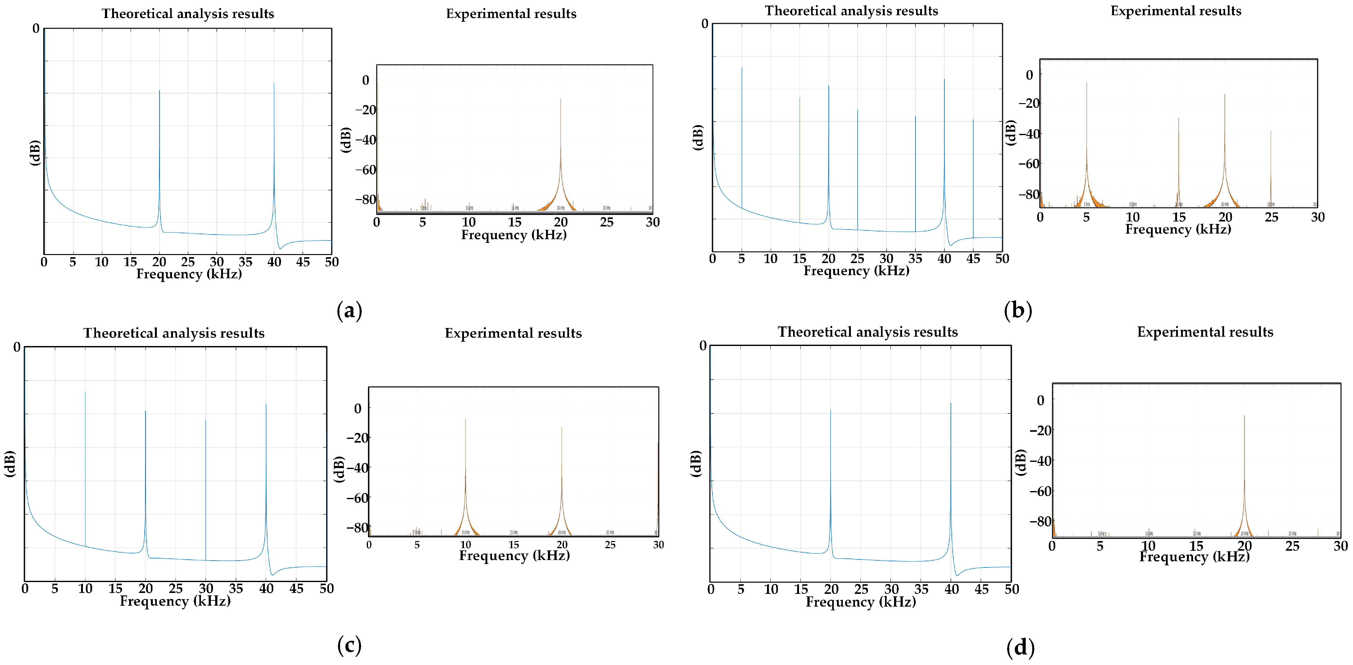
Figure 14a–d present the PSD analysis results of stator current for four strategies, including mechanical position sensor control, FF-IN method, 23 PRC-IN method, and 2(3&1) PRC-IN method, with a switching frequency of 20 kHz for all four strategies. In Figure 14a–d, the left side shows the theoretical analysis results, while the right side shows the experimental results.
Figure 14.
PSD analysis results of stator current. (a) Sensor control; (b) FF-IN method; (c) 23 PRC-IN method; (d) 2(3&1) PRC-IN method.
Figure 14a show PSD result with fixed 20 kHz switching frequency. As seen in Figure 14a, the discrete spectrums are concentrated at the integer multiples of the switching frequency, and it means that this discrete spectrum has nothing to do with the injection signals. Figure 14b shows the PSD results obtained using the conventional FF-IN method with a fixed injection frequency of 5 kHz. It can be observed that the discrete spectrum is not only concentrated at the switching frequency and its integer multiples, but also appears at the injection frequency and its odd multiples. This can lead to severe high-frequency noise, which affects the widespread application of sensorless control methods. Figure 14c shows the PSD results of the 23 PRC-IN method under joint injection at frequencies of 10/3 kHz and 10 kHz. It can be observed that in addition to being concentrated at the switching frequency and its integer multiples, the discrete spectrum also appears at the least common multiple of the two injection frequencies, which is 10 kHz, and at odd multiples of this frequency. Compared to the conventional FF-IN method, it is evident that this approach can eliminate some high-frequency noise and reduce the noise pollution caused by sensorless control methods. Figure 14d shows the PSD results of the 2(3&1) PRC-IN method under joint injection at frequencies of 2.5 kHz and 5 kHz. It can be observed that, compared to the conventional FF-IN method and the 23 PRC-IN method, the discrete spectrum in the 2(3&1) PRC-IN method is concentrated only at the switching frequency and its integer multiples, with no discrete harmonics at other frequencies. This indicates that high-frequency harmonics have been completely eliminated, significantly expanding the application scope of sensorless control.
5. Conclusions
PMSMs are widely used in various fields due to their advantages such as high power density, high efficiency, and high power factor. However, mechanical position sensor failures can cause various serious safety issues. To address the problem of harsh noise caused by conventional fixed-frequency square-wave injection in sensorless control at low-speed ranges, this paper introduces the principle of conventional fixed-frequency square-wave injection for sensorless control. Based on this, it analyzes the reasons for the generation of sharp noise caused by the conventional fixed-frequency square-wave signal injection method. Based on this analysis, a square-wave injection method based on 23 pseudo-random coding is proposed. By changing the frequency and amplitude of the injection signal, the current power spectral density is expanded, effectively reducing the sharp noise caused by high-frequency square-wave injection. To further eliminate the high-frequency sharp noise completely, an improved 2(3&1) pseudo-random coding square-wave injection method is proposed based on the 23 pseudo-random coding square-wave injection method. This method can further expand the current power spectral density and completely eliminate the sharp noise caused by high-frequency square-wave injection.
Furthermore, IPMSM has a salient pole effect, so the method proposed in this paper can also be applied to sensorless control of IPMSM. In addition, it can be expected that the 2n (n = 5, 7, 9, …) PRC high-frequency square-wave injection method also has the ability to eliminate the sharp noise caused by the conventional fixed-frequency square-wave injection method. However, with the superposition and mutual influence of multiple square-waves with different frequencies and amplitudes (three or more), the difficulty of implementing square wave injection and demodulating current signals also increases. Therefore, further research is needed to address the corresponding issues.
Author Contributions
Conceptualization, M.J., X.L. and X.W.; methodology, W.X. and M.X.; software, M.J. and M.X.; validation, M.J., W.X. and M.X.; formal analysis, M.J. and W.X.; data curation, M.J. and W.X.; writing—original draft preparation, M.J.; writing—review and editing, W.X. and M.X.; supervision, X.L. and X.W.; project administration, X.L. and X.W. All authors have read and agreed to the published version of the manuscript.
Funding
This research received no external funding.
Institutional Review Board Statement
This study did not require ethical approval because it did not involve humans or animals.
Informed Consent Statement
Not applicable.
Data Availability Statement
The original contributions presented in the study are included in the article, further inquiries can be directed to the corresponding author.
Conflicts of Interest
The authors declare no conflicts of interest.
Appendix A
Table A1 summarizes the key parameters and specifications.
Table A1.
Setup parameters.
References
- Janiszewski, D. Sensorless PMSM Speed Control Using an FPGA-Implemented Unscented Kalman Filter. Appl. Sci. 2026, 16, 5429. [Google Scholar] [CrossRef] [Scilit]
- Ruan, B.; Li, G.; Liu, L.; Fan, Y. Sensorless Control of PMSM Based on Fuzzy Sliding Mode Observer and Non-Singular Terminal Sliding Mode Control. Appl. Sci. 2026, 16, 2544. [Google Scholar] [CrossRef] [Scilit]
- Corley, M.; Lorenz, R. Rotor position and velocity estimation for a salient-pole permanent magnet synchronous machine at standstill and high speeds. IEEE Trans. Ind. Appl. 1998, 34, 784–789. [Google Scholar] [CrossRef] [Scilit]
- Tian, B.; An, Q.; Sun, D. Initial position estimation for surface permanent magnet synchronous motors based on magnetic saturation effect. Trans. China Electrotech. Soc. 2016, 31, 155–164. [Google Scholar]
- Sohel, R.M.; Wu, W.; Ji, R.; Fang, Z.; Liu, K. Sliding Mode Observer-Based Sensorless Control Strategy for PMSM Drives in Air Compressor Applications. Appl. Sci. 2025, 15, 11206. [Google Scholar] [CrossRef] [Scilit]
- Lu, Q.; Gao, S.; Zhang, T.; Zheng, S.; Mo, L. Rotor Position Estimation Strategy Based on Rotating High-Frequency Voltage Injection Using Synchronous Frequency Filter. Appl. Sci. 2022, 12, 11945. [Google Scholar] [CrossRef] [Scilit]
- Lu, J.; Liu, J.; Wei, L. Estimation of the initial rotor position for permanent magnet synchronous motors. Trans. China Electrotech. Soc. 2015, 30, 105–111. [Google Scholar]
- SOzturk, B.; Kivanc, O.C.; Aksoz, A.; Hegazy, O. Rotor Position Alignment of FSTPI Based PMSM Drive Using Low Frequency Signal Injection. Appl. Sci. 2020, 10, 7397. [Google Scholar] [CrossRef] [Scilit]
- Yoon, Y.-D.; Sul, S.-K.; Morimoto, S.; Ide, K. High-bandwidth sensorless algorithm for AC machines based on square wave type voltage injection. IEEE Trans. Ind. Appl. 2011, 47, 1361–1370. [Google Scholar] [CrossRef] [Scilit]
- Kim, D.; Kwon, Y.-C.; Sul, S.-K.; Kim, J.-H.; Yu, R.-S. Suppression of injection voltage disturbance for high frequency square-wave injection sensorless drive with regulation of induced high frequency current ripple. IEEE Trans. Ind. Appl. 2016, 52, 302–312. [Google Scholar] [CrossRef] [Scilit]
- Khan, A.; Mohammed, O. Neural network based modeling of audible noise for high frequency injection based position estimation for PM synchronous motors at low and zero speed. In 2009 IEEE Electric Ship Technologies Symposium; IEEE: New York, NY, USA, 2009; pp. 119–122. [Google Scholar]
- Wang, G.; Xiao, D.; Zhang, N.; Zhang, X.; Wang, W.; Xu, D. Low frequency pulse voltage injection scheme-based sensorless control of IPMSM drives for audible noise reduction. IEEE Trans. Ind. Electron. 2017, 64, 8415–8426. [Google Scholar] [CrossRef] [Scilit]
- Shimamoto, K.; Morimoto, S.; Fukumaru, S. Sensorless control based on position estimation by switching operation of modified PWM. In IECON 2016—42nd Annual Conference of the IEEE Industrial Electronics Society; IEEE: New York, NY, USA, 2016; pp. 2898–2903. [Google Scholar]
- Hosogaya, Y.; Kubota, H. Sensorless control method of IPMSM with current derivative information of q-axis without high frequency component injection at low speed region. In 2013 IEEE ECCE Asia Downunder; IEEE: New York, NY, USA, 2013; pp. 799–803. [Google Scholar]
- Taniguchi, S.; Yasui, K.; Yuki, K. Noise reduction method by injected frequency control for position sensorless control of permanent magnet synchronous motor. In 2014 International Power Electronics Conference (IPEC-Hiroshima 2014—ECCE ASIA); IEEE: New York, NY, USA, 2014; pp. 2465–2469. [Google Scholar]
- Wang, G.; Yang, L.; Zhang, G.; Zhang, X.; Xu, D. Comparative Investigation of Pseudorandom High-Frequency Signal Injection Schemes for Sensorless IPMSM Drives. IEEE Trans. Power Electron. 2017, 32, 2123–2132. [Google Scholar] [CrossRef] [Scilit]
- Zhang, Y.; Yin, Z.; Liu, J.; Zhang, R.; Sun, X. IPMSM Sensorless Control Using High-Frequency Voltage Injection Method with Random Switching Frequency for Audible Noise Improvement. IEEE Trans. Ind. Electron. 2020, 67, 6019–6030. [Google Scholar] [CrossRef] [Scilit]
- Wang, G.; Yang, L.; Yuan, B.; Zhang, G.; Xu, D. Pseudo-random high-frequency square-wave voltage injection based sensorless control of IPMSM drives for audible noise reduction. IEEE Trans. Ind. Electron. 2016, 63, 7423–7433. [Google Scholar] [CrossRef] [Scilit]
- Chen, J.; Fan, Y.; Wang, W.; Lee, C.H.T.; Wang, Y. Sensorless control for SynRM drives using a pseudo-random high-frequency triangular-wave current signal injection scheme. IEEE Trans. Power Electron. 2022, 37, 7122–7131. [Google Scholar] [CrossRef] [Scilit]
- Jiang, H.; Sumner, M. Sensorless torque control of a PM motor using modified HF injection method for audible noise reduction. In Proceedings of the 2011 14th European Conference on Power Electronics and Applications; IEEE: New York, NY, USA, 2011; pp. 1–8. [Google Scholar]
- Wang, G.; Zhou, H.; Zhao, N.; Li, C.; Xu, D. Sensorless control of IPMSM drives using a pseudo-random phase-switching fixed-frequency signal injection scheme. IEEE Trans. Ind. Electron. 2018, 65, 7660–7671. [Google Scholar] [CrossRef] [Scilit]
- Li, C.; Wang, G.; Zhang, G.; Zhao, N.; Xu, D. Adaptive pseudorandom high-frequency square-wave voltage injection based sensorless control for SynRM drives. IEEE Trans. Power Electron. 2021, 36, 3200–3210. [Google Scholar] [CrossRef] [Scilit]
- He, J. Closed addition in a three-element set and 2n sequence pseudo-random signal coding. J. Cent. South Univ. 2010, 41, 632–637. [Google Scholar]
- He, J. New research progress in theory and application of wide field electromagnetic method. Geophys. Geochem. Explor. 2020, 44, 985–990. [Google Scholar]

Disclaimer/Publisher’s Note: The statements, opinions and data contained in all publications are solely those of the individual author(s) and contributor(s) and not of MDPI and/or the editor(s). MDPI and/or the editor(s) disclaim responsibility for any injury to people or property resulting from any ideas, methods, instructions or products referred to in the content. |
© 2026 by the authors. Licensee MDPI, Basel, Switzerland. This article is an open access article distributed under the terms and conditions of the Creative Commons Attribution (CC BY) license.