


Abstract
High-efficiency industrial motors are increasingly important for reducing energy consumption, operating costs, and indirect carbon emissions. This study presents a comparative evaluation of IE2 and IE4 efficiency class induction motors with the same rated power and frame size through finite element analysis and prototype testing. Two-dimensional transient electromagnetic models were developed in ANSYS Maxwell to investigate magnetic flux distribution, torque behavior, losses, and steady-state performance, and the numerical results were experimentally validated according to IEC 60034-2-1 procedures. The results show that the IE4 motor provides a more balanced magnetic flux distribution, lower local saturation tendency, reduced torque ripple, and lower total losses than the IE2 motor. Experimental measurements confirmed the numerical predictions with good agreement, particularly at the rated operating point. In addition to higher efficiency, the IE4 motor exhibited stronger starting and breakdown torque characteristics, indicating superior load-handling capability. An economic assessment based on a representative duty cycle showed that the relative additional cost of the IE4 motor can be recovered within approximately 0.81 years, while lower annual electricity consumption also reduces indirect CO2 emissions. Furthermore, the IE4 prototype operated at a lower thermal steady-state temperature, supporting longer insulation life and improved long-term reliability. Overall, the findings demonstrate that replacing conventional IE2 motors with IE4 alternatives is not merely an efficiency upgrade, but also a technically robust, economically justified, and environmentally effective strategy for sustainable industrial systems.
1. Introduction
Electric motors are among the most widely used equipment for converting electrical energy into mechanical energy in industry; therefore, motor efficiency constitutes a critical design criterion in terms of both energy consumption and operating costs. In this context, international efficiency classes for line-operated AC motors are defined under the IEC 60034-30-1 standard, where efficiency classes ranging from IE1 to IE5 and their scope conditions are presented in detail [1]. This classification provides a framework that directly influences not only nameplate efficiency but also motor design philosophy, material selection, and the distribution of loss components. In addition, IEC 60034-1 is accepted as a fundamental reference document for the engineering evaluation of rotating electrical machines by defining rated values, duty types, and performance characteristics [2]. Similarly, IEC 60034-2-1 defines standard methods for experimentally determining motor losses and efficiency, thereby providing a critical methodological basis particularly for loss segregation, determination of additional losses, and efficiency verification [3]. In parallel, the current ecodesign regulations of the European Union were established under Commission Regulation (EU) 2019/1781, with phased implementation stages entering into force on 1 July 2021 and 1 July 2023, making IE3 and IE4 efficiency levels mandatory for specific motor categories [4]. These developments have transformed high-efficiency motor design from a purely academic research topic into a direct industrial necessity.
The significant role of electric motors and the motor-driven systems they operate within the global energy system makes the transition toward high-efficiency motors even more critical. International assessments indicate that motor-driven systems account for more than 40% of global electricity consumption, while electric motor systems represent approximately 60–70% of industrial electricity use. At this scale, even relatively modest improvements in motor efficiency can create substantial impacts on total energy demand and industry-related emissions. Therefore, efficiency upgrades such as the transition from IE2 to IE4 should be regarded not only as equipment-level performance improvements, but also as one of the principal implementation areas of industrial energy-efficiency policies [5,6].
In addition, the transition toward high-efficiency motors is currently associated not only with reducing energy costs, but also with minimizing environmental impact in industry and supporting sustainable production targets. Recent studies examining the environmental impacts of electric motor technologies through a life-cycle perspective have shown that energy performance during the use phase constitutes a dominant share of total environmental impact. This indicates that higher efficiency motor classes should be considered not merely as technical improvements, but also as practical tools for the transition toward sustainable industry [7].
Induction motors remain one of the most dominant electric motor technologies due to their robust structure, low maintenance requirements, manufacturing maturity, and widespread industrial infrastructure. Nevertheless, significant developments have been observed in recent years in conventional induction motor design to achieve higher efficiency classes. These developments include multidimensional approaches such as the use of low-loss electrical steel, more balanced magnetic flux distribution, optimization of rotor and stator geometries, and drive-assisted operating strategies. Recent review studies indicate an increasing research focus on electromagnetic design optimization, loss minimization, and overall system efficiency [8]. Furthermore, recent studies have shown that not only fixed operating-point efficiency, but also efficiency maps over wide operating ranges, have become increasingly important. In this respect, comparing efficiency distributions under different load and speed conditions provides a more realistic representation of actual operating performance [9].
An increase in efficiency class does not merely imply higher rated-point efficiency; it also leads to significant effects on loss distribution, torque characteristics, magnetic loading level, thermal behavior, and initial investment cost. Therefore, the accurate understanding of loss components plays a critical role in both high-efficiency motor design and the evaluation of real operating performance. Moreover, the importance of transitioning to a higher efficiency class is not limited to improvements in label efficiency alone; cumulative energy consumption during service life, associated emission impacts, and total cost of ownership should also be considered. In this regard, Goman et al. compared IE2, IE3, and IE4 induction motors in terms of energy consumption and CO2 emissions, showing that higher efficiency classes can provide significant advantages in life-cycle performance. Such studies contribute to the evaluation of differences between efficiency classes particularly from the perspectives of system-level energy consumption, emission impact, and payback behavior [10].
Likewise, policy- and market-based transition scenarios indicate that replacing old and low-efficiency motors with higher efficiency classes offers considerable energy-saving potential. According to the current product policy assessment of the European Commission, the revised motor regulation is expected to deliver annual savings of 106 TWh by 2030, reduce approximately 40 million tons of CO2 emissions, and lower annual energy bills by nearly EUR 20 billion for households and industry. In addition, recent European evaluations suggest that accelerated replacement of old motors alone could provide an additional saving potential of approximately 25 TWh annually. These findings place the combined technical and economic evaluation of IE2 and IE4 motors directly within the context of green transition and industrial competitiveness rather than merely an academic topic [11].
The influence of manufacturing processes has also become an important research topic in high-efficiency motor design. In particular, the cutting method of electrical steel laminations may alter magnetic properties due to mechanical stresses generated near cut edges, thereby directly affecting iron losses. In an experimental study conducted by Bayraktar and Turgut, laser cutting and punching methods were shown to have different effects on total magnetic losses and motor efficiency [12]. In addition, mechanical components such as friction and windage losses can account for a growing share of total losses, particularly at high speeds, making their accurate modeling increasingly important. Gebauer et al. demonstrated the necessity of combined experimental and numerical evaluation of aerodynamic losses [13].
In recent years, increasing attention has also been given to optimizing motor efficiency not only at the design stage but throughout operational life. Flux- and slip-optimization-based control strategies can improve total system efficiency by reducing losses under light-load conditions [14]. In addition, digital model-based approaches enable real-time monitoring and optimization of motor performance [15]. Furthermore, studies on in-field estimation of efficiency and output power have increased, demonstrating that motor performance can be predicted through non-intrusive methods [16]. In this context, validation of numerical modeling results through experimental test data is of critical importance not only for demonstrating design accuracy, but also for reliably assessing loss predictions, performance maps, and real operating behavior.
However, studies in the literature that holistically evaluate two different induction motor efficiency classes under identical operating conditions in terms of electromagnetic analysis, loss segregation, experimental validation, and cost are still limited. In particular, studies comparing IE2 and IE4 motors of the same power class but with different steel grades and stack lengths remain underrepresented. Furthermore, recent studies indicate that preserving the existing industrial stator platform while transitioning toward alternative high-efficiency motor solutions constitutes an important research direction from both technical and economic perspectives. New approaches based on a common stator platform emphasize that efficiency improvements can be achieved through rotor-side modifications while maintaining existing manufacturing infrastructure and associated cost advantages. In this respect, establishing the reference behavior of conventional induction motors across different efficiency classes provides a solid benchmark not only for induction motor comparisons, but also for future alternative topologies [17].
On the other hand, industrial energy transition does not always imply the installation of entirely new systems; upgrading the existing motor fleet with more efficient solutions is also emerging as an important pathway. In this context, studies on remanufacturing motors or converting them into higher performance solutions have shown meaningful reductions in environmental impact and carbon emissions. Likewise, recent energy-efficiency assessments identify the improvement of motor system efficiency as a priority action area for the industrial sector. This perspective demonstrates that the IE2-to-IE4 transition should be considered not only as product-level modernization, but also as part of a broader industrial energy transformation [18].
In this study, IE2 and IE4 induction motors of the same power class are compared within a multidimensional framework. First, the electromagnetic behavior, flux density distributions, torque ripple, and major loss components of the motors are investigated using an ANSYS Maxwell 2D finite element model. Subsequently, IEC 60034-2-1 based experimental tests are conducted on manufactured prototype motors, and the numerical results are validated against experimental data. Finally, the effects of transition to a higher efficiency class on initial investment and operating cost are assessed, thereby complementing the technical findings with an economic perspective. In this respect, the study provides a holistic evaluation of IE2 and IE4 induction motors not only in terms of efficiency value, but also with respect to electromagnetic performance, loss structure, experimental agreement, and cost dimensions. Moreover, by jointly evaluating the loss structure and economic performance of IE2 and IE4 motors, the study contributes to considering the transition toward high-efficiency motors not merely as a technical improvement, but also as a strategic transformation tool aligned with sustainable industry and energy-efficiency goals.
2. Materials and Methods
In this section, the motor configurations investigated in the study, the numerical modeling approach, the prototype manufacturing process, the experimental validation procedure, and the framework for the economic and sustainability assessment are presented. First, the main technical specifications of the IE2 and IE4 induction motors are provided. Next, the finite element modeling approach used for the electromagnetic performance analysis is described. Subsequently, the prototype manufacturing process and the laboratory test procedures conducted in accordance with the relevant standards are presented. Finally, the methodology used for evaluating energy consumption, cost, payback period, and CO2 emissions is explained.
2.1. Investigated Motors and Main Technical Specifications
In this study, two different induction motor configurations with the same power rating were investigated. The first is an IE2-class induction motor, which is widely used in existing industrial applications, while the second is an IE4-class induction motor representing a higher level of energy efficiency. Considering both motors within the same power and frame class enables a direct comparison of the effects of efficiency-class improvement on electromagnetic performance, loss characteristics, experimental behavior, and economic outcomes.
The main geometric difference between the investigated motors is the stack length. The IE2 motor has a stack length of 80 mm, whereas the IE4 motor was designed with a stack length of 135 mm. In addition, M700-50A electrical steel was used in the IE2 motor, while the IE4 motor employed M400-50A electrical steel with lower loss characteristics. In both motors, distributed stator windings, copper conductors, a three-phase configuration, a four-pole design, and operating conditions of 400 V and 50 Hz were adopted. Accordingly, the comparison was not made between different motor types, but rather between the technical and experimental performances of two different efficiency classes within the same application framework.
While the IE2 motor represents the conventional solution widely used in current industrial infrastructure, the IE4 motor represents an improved design approach aimed at achieving a higher efficiency level. Therefore, investigating these two motors together is meaningful not only for assessing the technical consequences of the efficiency-class difference, but also for revealing the engineering and application-related dimensions of the transition from IE2 to IE4. The main technical specifications of the investigated IE2 and IE4 induction motors are presented in Table 1.
Table 1.
Main Specifications of the Investigated IE2 and IE4 Induction Motors.
2.2. Finite Element Modeling Method
A two-dimensional finite element analysis was conducted to evaluate the electromagnetic performances of the investigated IE2 and IE4 induction motors. The numerical modeling studies were carried out in ANSYS Maxwell 2D, while the cross-sectional geometries of the motors were initially created using ANSYS RMxprt and subsequently transferred to the Maxwell 2D environment for detailed field analyses. This approach enables the rapid modeling of motor geometries widely used in industry and allows detailed electromagnetic field investigations to be performed.
For both motors, the stator slot structure, winding arrangement, number of poles, and main frame dimensions were kept unchanged, whereas the stack length and active magnetic material parameters were incorporated into the model to represent design variations associated with the efficiency class. For the IE2 motor, an 80 mm stack length and M700 electrical steel were adopted, while for the IE4 motor, a 135 mm stack length and M400 electrical steel with lower specific losses were defined. In this way, the impact of efficiency-class upgrading was assessed numerically not only in terms of nominal efficiency, but also with respect to active material selection and magnetic sizing.
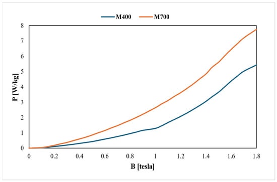
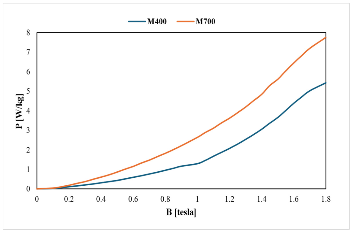
In the analyses, a supply frequency of 50 Hz, a rated voltage of 400 V, and three-phase sinusoidal excitation conditions were used. The winding connections were modeled based on a star connection. In both motors, copper was defined as the stator winding conductor material, aluminum was used for the rotor bars and end rings, and Carbon Steel 1030 was assigned as the shaft material. For the magnetic material models, manufacturer-based B–H curves and specific iron-loss characteristics were employed. The specific core-loss curves of the M700 and M400 electrical steels used in the investigated motors under 50 Hz operating conditions are presented in Figure 1. These curves were used as the basis for modeling the loss behavior of the materials at the operating frequency, and the corresponding data were validated by Epstein testing.
Figure 1.
Specific core-loss curves of the M700 and M400 electrical steels at 50 Hz used in the finite element model.
To represent the winding resistance and the associated copper losses more realistically, the cold resistance values of the motors at an ambient temperature of 20 °C were measured experimentally and compared with the phase resistance values calculated in the RMxprt environment. In order to achieve consistency with the measured resistance values, the end-winding length was adjusted parametrically, and the validated values were adopted in the finite element model.
A transient solution method was preferred in order to examine the time-dependent electromagnetic behavior. Rotor motion was defined as rotational motion in the Maxwell 2D environment, and within the voltage-fed solution approach, the slip value was not assigned directly as a fixed parameter but instead developed inherently during the solution as a result of the electromagnetic interaction. Initial starting behavior, torque oscillations, flux density distributions, and the transition to steady-state operation were evaluated using this method. The total solution time and time-step size were selected to represent both transient and steady-state behavior with sufficient accuracy. Quantities such as average torque, torque ripple, phase currents, loss components, and air-gap flux density were extracted from the steady-state operating region.
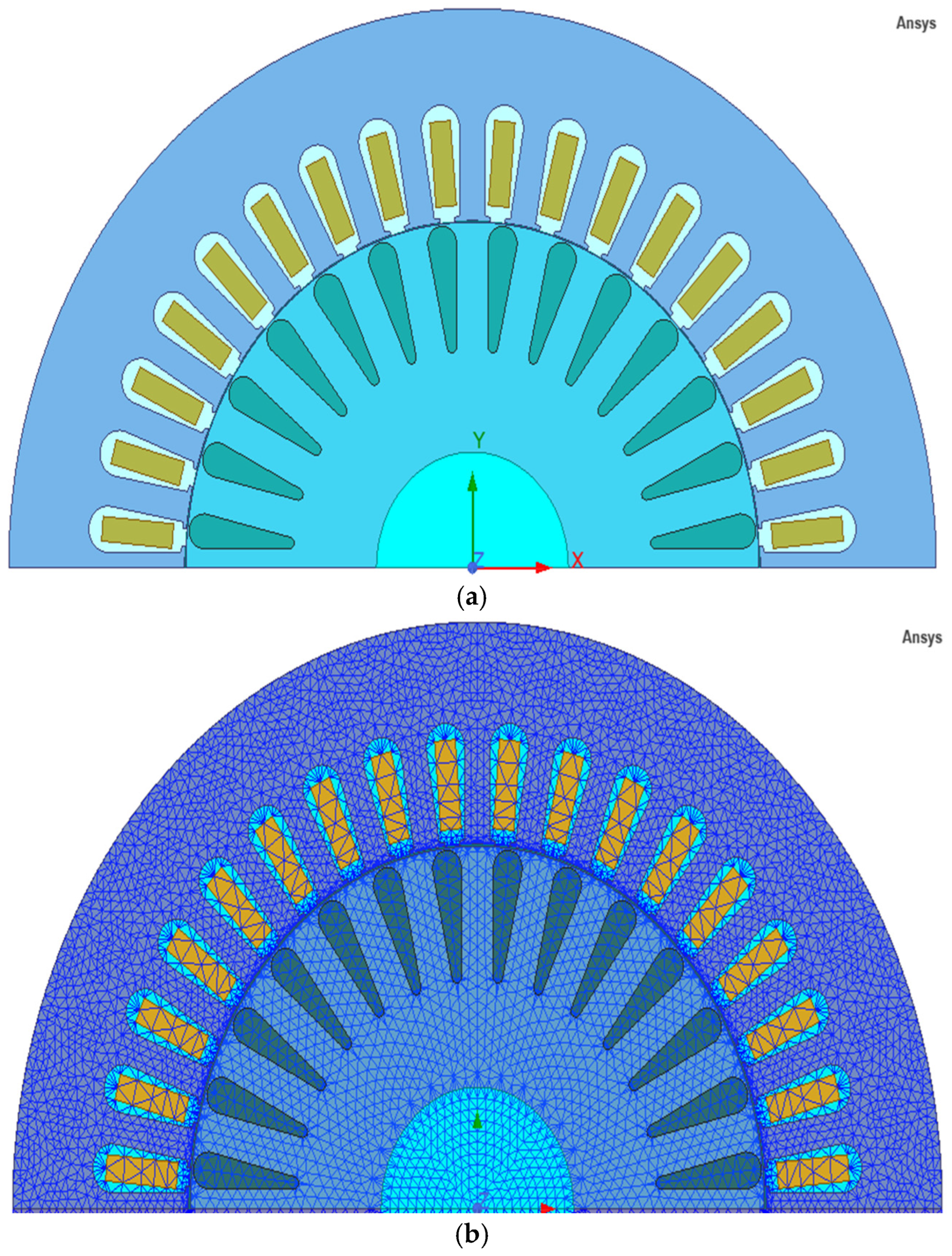
To evaluate the electromagnetic performance of the investigated motors, two-dimensional transient finite element models were established, and the cross-sectional geometry together with the adopted mesh structure is presented in Figure 2. The mesh was locally refined especially in the air gap, tooth tips, rotor slots, and conductor regions. In this way, high flux gradients and leakage-field effects were intended to be resolved more accurately. Based on preliminary investigations performed at different mesh densities, a balanced mesh structure was selected in terms of solution time and accuracy.
Figure 2.
Two-dimensional transient finite element model developed for the investigated motors: (a) cross-sectional geometry; (b) refined mesh structure used in the numerical analysis.
The main finite element analysis parameters of the investigated models are presented in Table 2.
Table 2.
Finite Element Model and Analysis Parameters of the Investigated Motors.
2.3. Prototype Manufacturing and Experimental Test Procedure
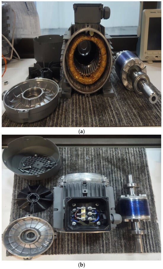
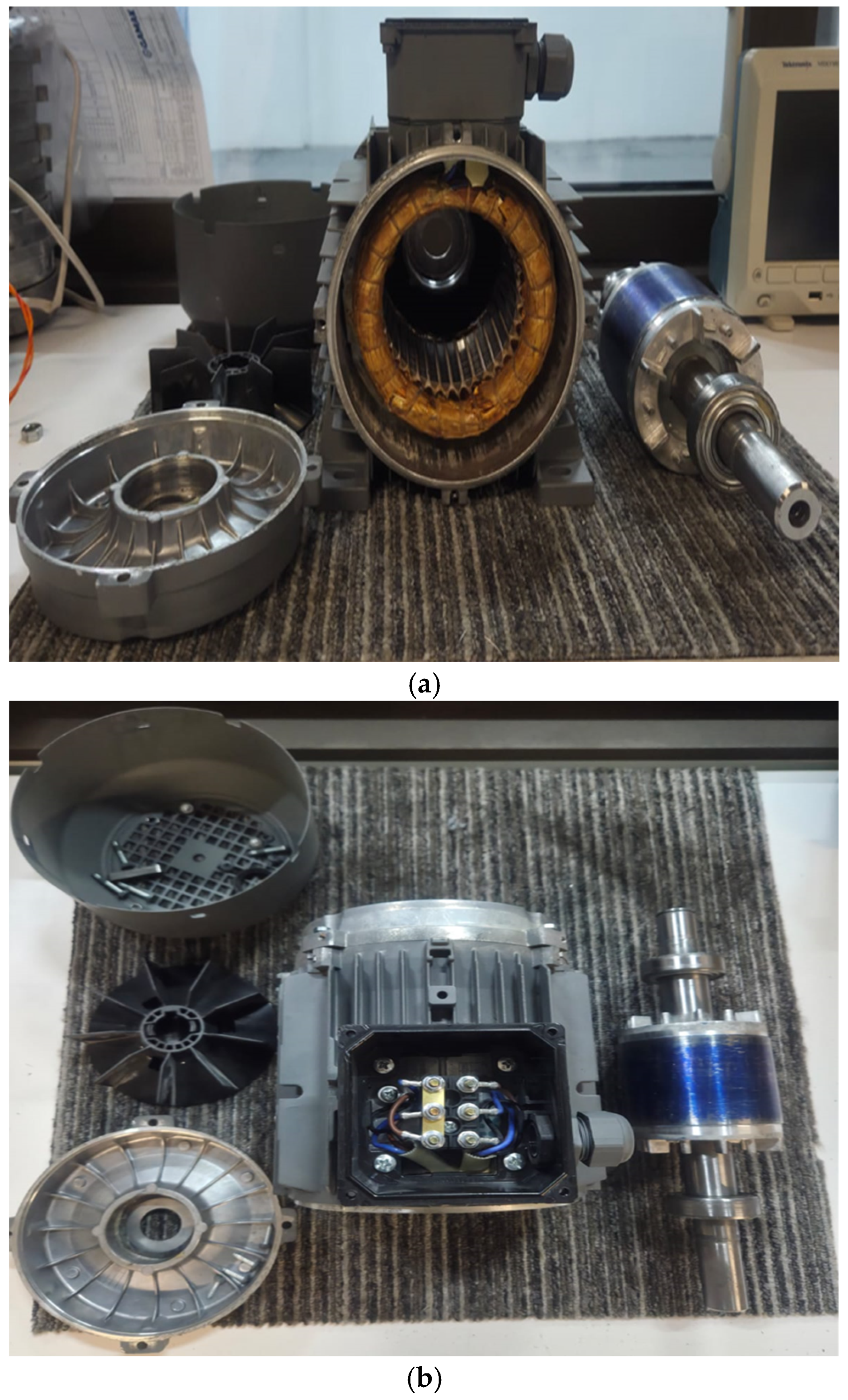
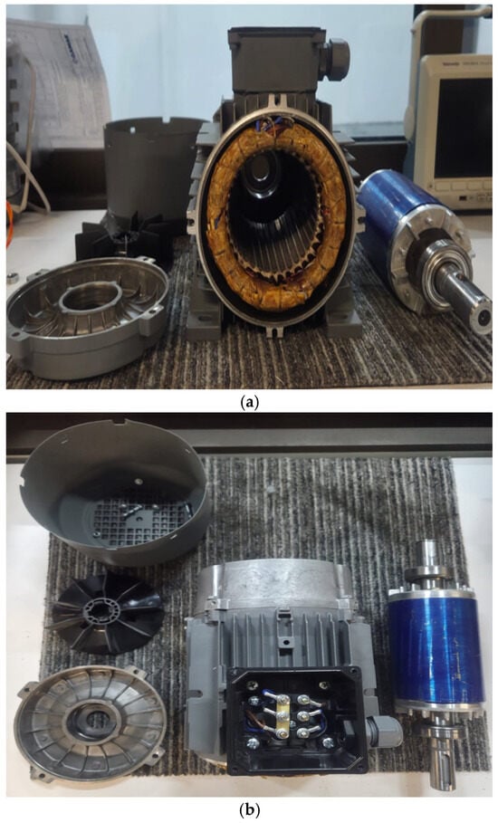
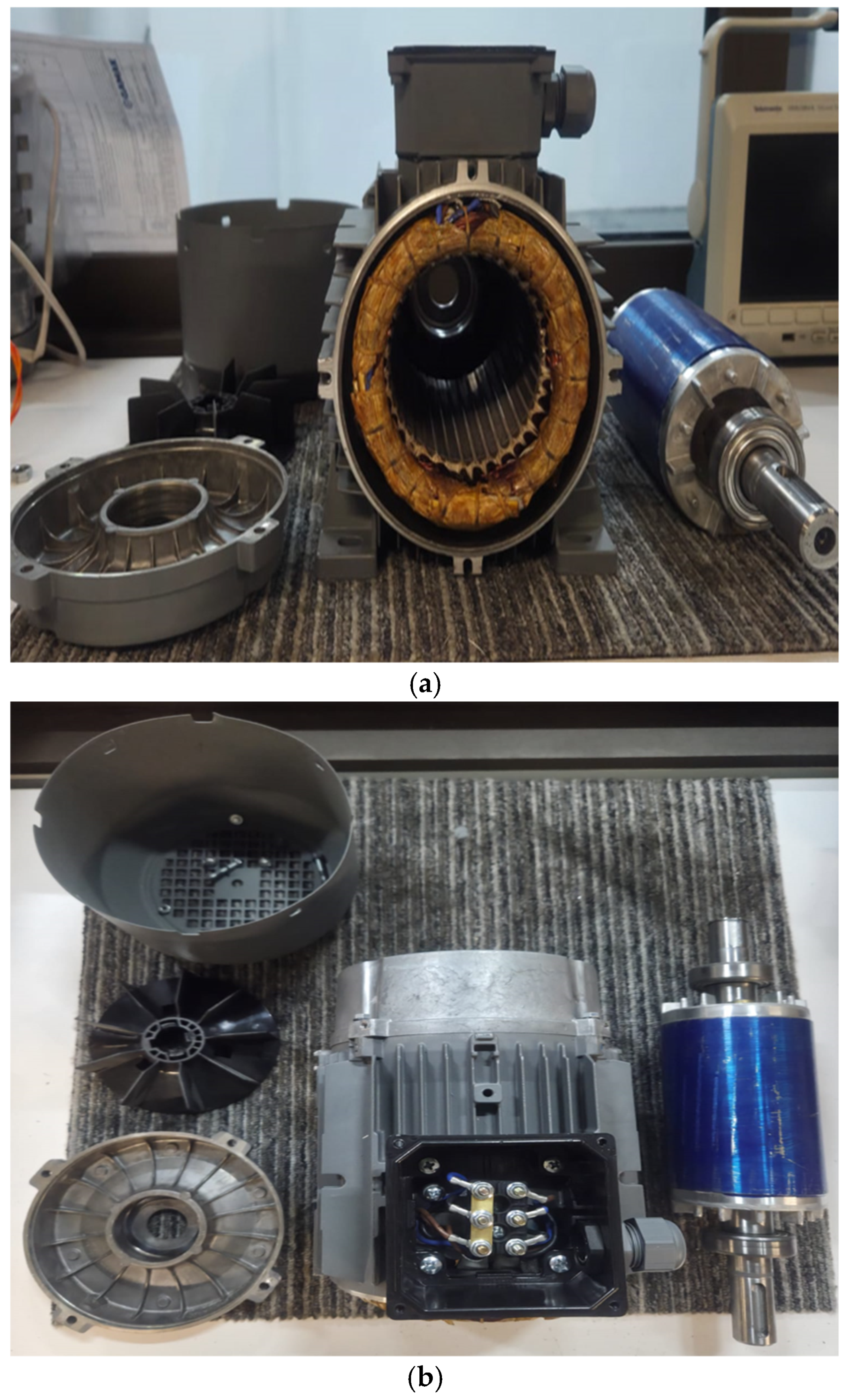
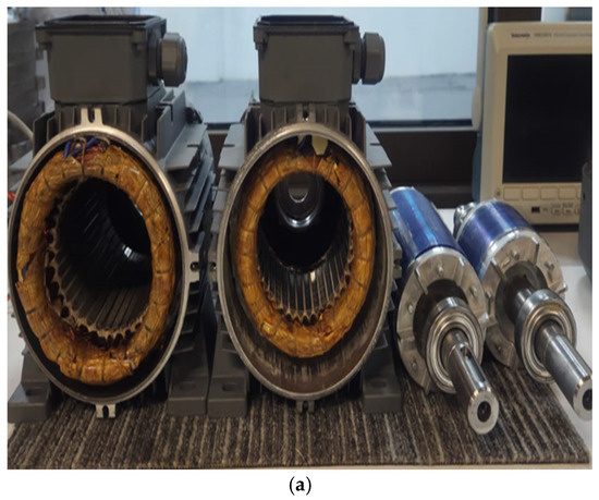
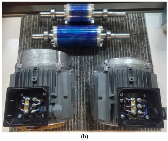
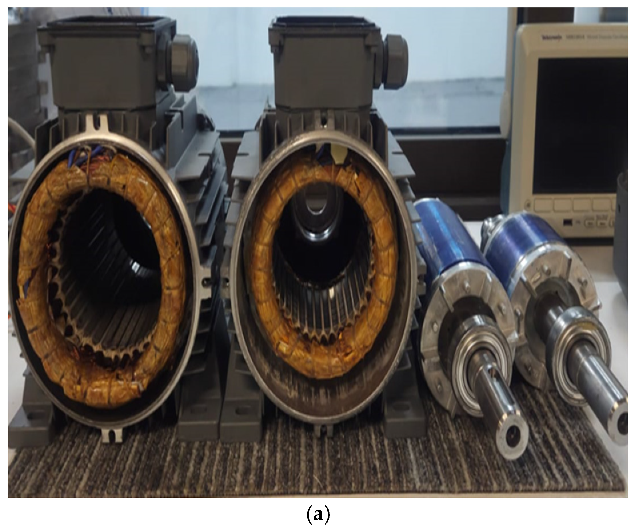
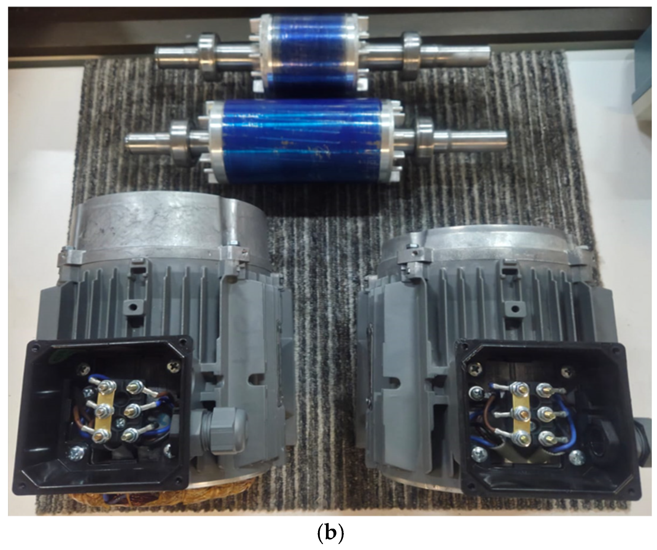
In order to validate the numerical results obtained from the finite element analyses and to compare the motors with different efficiency classes under real operating conditions, the IE2 and IE4 induction motor prototypes investigated in this study were manufactured. Both motors were prepared within the same power and frame class, and the rotor, stator, housing, and assembly components were produced using industrial manufacturing infrastructure in accordance with the relevant design parameters. The semi-finished and pre-assembly components of the prototypes are presented in Figure 3 and Figure 4, respectively. These visuals show the stator core, wound stator structure, rotor, shaft, and the main mechanical assembly components. During the manufacturing process, lamination stacking, formation of the rotor cage structure, bearing and shaft assembly, balancing operations, and final assembly steps were completed, and the motors were made ready for testing. In addition, the main dimensional difference arising from the stack length is clearly illustrated in Figure 5, which presents a comparative view of the IE2 and IE4 induction motor prototypes.
Figure 3.
Semi-finished and pre-assembly components of the IE2 induction motor prototype: (a) front-perspective view of the motor components; (b) top-perspective view of the motor components (adapted from [17] following CC-BY 4.0 licence).
Figure 4.
Semi-finished and pre-assembly components of the IE4 induction motor prototype: (a) front-perspective view of the motor components; (b) top-perspective view of the motor components (adapted from [17] following CC-BY 4.0 licence).
Figure 5.
Dimensional differences between the IE2 and IE4 induction motor prototypes: (a) front-perspective view of the motors; (b) top-perspective view of the motors (adapted from [17] following CC-BY 4.0 licence).
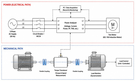
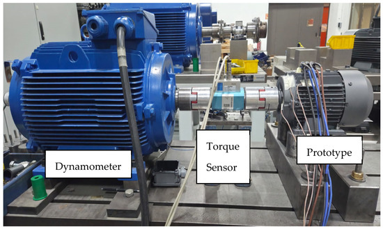
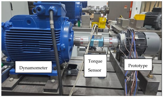
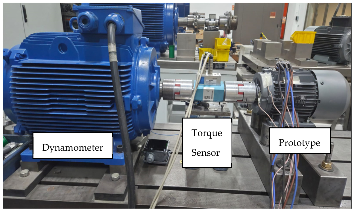
The experimental performance tests were carried out based on IEC 60034-2-1 and IEC 60034-1, which define the standard test procedures applicable to rotating electrical machines. The employed test infrastructure made it possible to operate the motors under load, monitor electrical and mechanical quantities simultaneously, and obtain performance data under controlled conditions. The tests were performed on a motor test bench equipped with a loading unit, torque transducer, speed sensor, power analyzer, current and voltage measurement instruments, and temperature sensors. To clarify the experimental configuration, a schematic representation of the test setup is presented in Figure 6. This schematic shows the electrical connection between the three-phase supply, power analyzer, and test motor, as well as the mechanical coupling between the test motor, torque transducer, and load machine. The IE2 and IE4 motors manufactured in the study and connected to the test setup are presented in Figure 7 and Figure 8, respectively. The accuracy classes of the measurement devices were selected in accordance with laboratory standards, and the necessary calibration checks were carried out prior to testing. Ambient conditions were monitored throughout the experiments, and care was taken to ensure similar operating conditions during the comparative measurements.
Figure 6.
Schematic representation of the experimental test setup, including the power analyzer, induction motor, torque transducer, load machine, speed sensor, and data acquisition system.
Figure 7.
Performance test setup of the IE2, 90-frame, 4-pole, 1.5 kW induction motor prototype conducted in the R&D laboratory of GAMAK Electric Motors (adapted from [17] following CC-BY 4.0 licence).
Figure 8.
Performance test setup of the IE4, 90-frame, 4-pole, 1.5 kW induction motor prototype conducted in the R&D laboratory of GAMAK Electric Motors (adapted from [17] following CC-BY 4.0 licence).
In this study, efficiency determination was carried out based on Method 2-1-1B specified in IEC 60034-2-1, namely the indirect method based on loss segregation. Within this method, motor efficiency was not measured directly; instead, total loss and efficiency were calculated using the data obtained from no-load and load tests. Through the no-load test, the iron loss, friction loss, and ventilation loss components were determined, thereby enabling the mechanical losses and iron losses to be separated mathematically. In addition, a speed–torque test was conducted to obtain the torque–speed characteristics of the motors. In this test, the motor was first energized and brought close to the synchronous speed region, after which controlled braking was applied using a dynamometer. As a result of the braking process, the motor speed was reduced to zero within approximately 30 s, and continuous data were acquired from the torque transducer throughout this period. Based on the obtained measurements, the starting torque, rated torque, pull-up torque, and breakdown torque were determined.
Mechanical alignment between the motor and the dynamometer is critical for test accuracy. Therefore, a laser shaft alignment device was used to align the test motors along the horizontal and vertical axes. In addition, the thermal behavior of the motors was continuously monitored during the test process. For this purpose, PT100 temperature sensors integrated into the test system were used to track the outer housing, winding, and bearing temperatures in real time. In this study, the steady-state operating condition was defined as the case in which the temperature variation in the motor did not exceed 1 K within a period of half an hour, and the measurement data were evaluated only after this condition had been satisfied. To ensure the reliability of the measurement infrastructure, periodic checks were regularly performed for all devices in the system requiring calibration. In this way, the reliability of voltage, current, power, speed, torque, and temperature measurements was maintained, and the accuracy of the experimental results was ensured.
The obtained experimental data were used for model validation by comparing them with the electromagnetic torque, current, efficiency, and loss components calculated from the finite element model. In this way, the agreement between numerical modeling and actual motor behavior was assessed, and the technical consequences of the transition from IE2 to IE4 were demonstrated from both numerical and experimental perspectives. Thus, the prototype manufacturing and test procedure defined in this section established a reliable basis for the experimental validation results presented in the subsequent sections.
2.4. Economic and Sustainability Assessment Method
In order to evaluate the technical performance differences between IE2- and IE4-class motors in terms of industrial applicability, additional analyses based on economic and sustainability considerations were carried out in this study. In this context, the transition to a higher efficiency class was assessed not only in terms of its effects on electromagnetic and experimental performance, but also with respect to energy consumption, operating cost, and carbon emissions.
Within the scope of the economic assessment, a representative industrial operating scenario was considered. The operating schedule was assumed as 16 h per day and 6 days per week (Monday–Saturday). After excluding the official public holidays in 2026 and the planned annual shutdown period, the net annual operating time was calculated as approximately 4488 h. This value was used as the baseline operating scenario for the calculations of energy consumption, operating cost, payback period, and carbon emissions.
In the annual energy consumption calculations, the efficiency values obtained under operating conditions close to the rated load of the motors were taken as the basis. Using the annual operating time defined in the selected operating scenario, the annual electrical energy consumption of the IE2 and IE4 motors was calculated. Subsequently, the annual operating costs were determined by considering the relevant unit electricity price.
In the economic analysis, the additional initial investment cost of the IE4 motor relative to the IE2 motor was compared with the annual energy savings, and the simple payback period approach was employed. In this way, the economic feasibility of transitioning to a higher efficiency class was evaluated under different utilization intensities.
Within the scope of the sustainability assessment, the carbon emission reduction potential was calculated based on the difference in electrical energy consumption. For this purpose, the relevant grid emission factor was used, and the annual CO2 emission difference between the IE2 and IE4 motors was determined. Thus, the transition from IE2 to IE4 was assessed quantitatively not only in economic terms, but also in terms of its environmental impact.
The motor configurations, cost assessment, and operating scenario presented in this study are used solely for academic comparison and validation purposes. The reported results correspond to the investigated prototype configurations and should not be interpreted as complete commercial design specifications or manufacturing data of GAMAK Electric Motors. Certain proprietary design details, manufacturing tolerances, detailed winding data, lamination drawings, rotor-bar dimensions, and process-related parameters are intentionally omitted to protect industrial know-how. For confidentiality reasons, the cost assessment is presented using normalized cost indices rather than actual commercial purchasing or manufacturing costs. The reported values are intended only to evaluate relative economic trends under the selected operating scenario.
3. Results
In this section, the findings obtained from the numerical analyses and prototype tests of the investigated IE2- and IE4-class induction motors are presented comparatively. First, the electromagnetic field distributions and the main performance characteristics of the motors were evaluated by means of finite element analyses, and then model validation was carried out through experimental tests performed on the prototype motors. Finally, based on the obtained technical data, the economic payback period and sustainability indicators were examined. In this way, the technical, economic, and environmental effects of the transition from IE2 to IE4 were presented through a holistic approach.
3.1. Electromagnetic Field Analysis
To compare the electromagnetic behaviors of the investigated IE2 and IE4 induction motors, finite element analyses were performed under rated operating conditions. Within this scope, the magnetic flux density distributions, flux-line patterns, air-gap magnetic flux density variations, and steady-state torque ripple characteristics of the motors were evaluated together. The obtained results reveal the effects of changes in active material selection, stack length, and magnetic loading level on electromagnetic performance as the efficiency class increases.
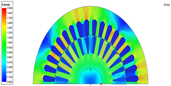
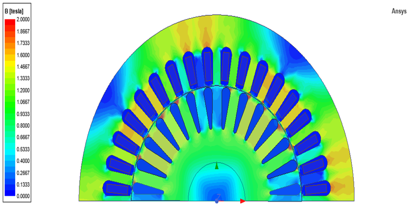
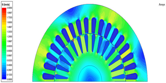
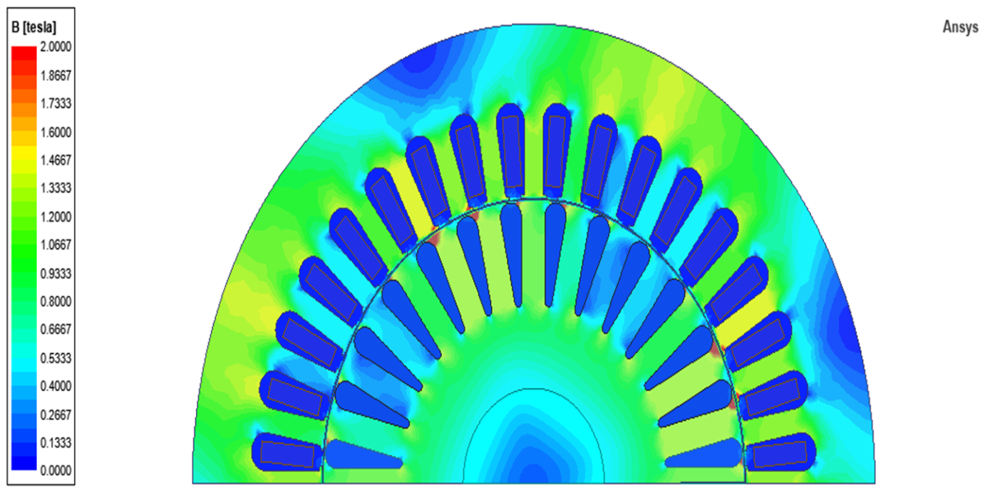
The magnetic flux density distributions of the IE2 and IE4 induction motors are presented in Figure 9 and Figure 10, respectively. Examination of these distributions shows that, in both motors, the highest flux density levels occur at the stator and rotor tooth tips and in the yoke transition regions. However, due to the use of M400 electrical steel and the larger stack length in the IE4 motor, the flux distribution is more balanced, whereas local flux density concentrations become more pronounced in the IE2 motor. This indicates that the tendency toward magnetic saturation is more dominant in certain regions of the IE2 motor, while the magnetic loading is distributed in a more controlled manner in the IE4 motor.
Figure 9.
Magnetic flux density distribution of the IE2 induction motor.
Figure 10.
Magnetic flux density distribution of the IE4 induction motor.
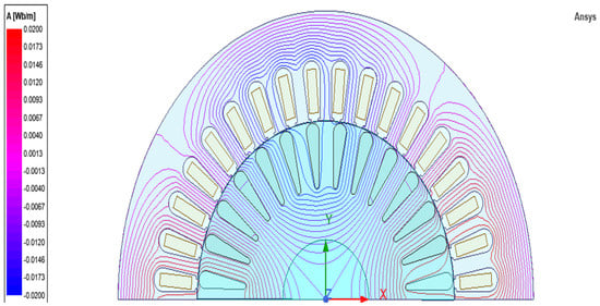
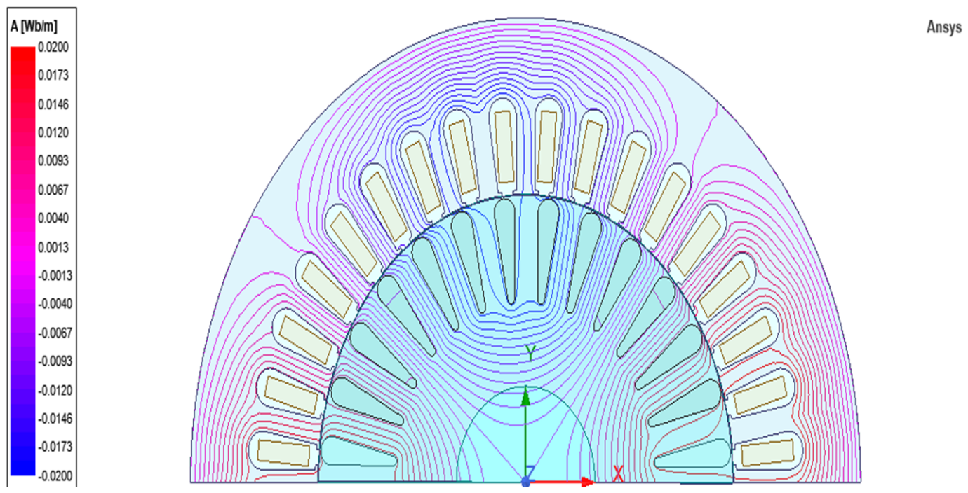
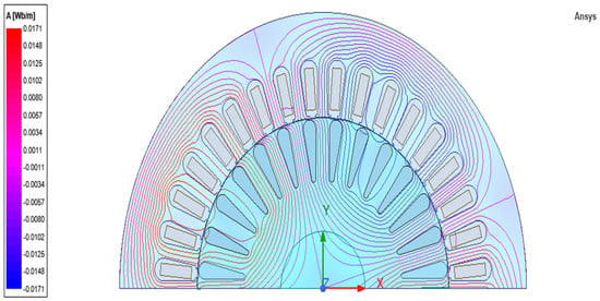
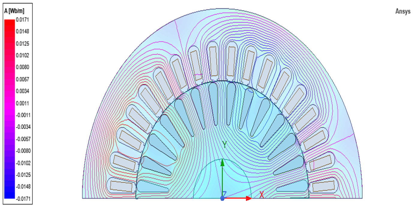
The flux-line distributions of the IE2 and IE4 motors are presented in Figure 11 and Figure 12, respectively. The flux lines show that, in both motors, the electromagnetic circuit closes as expected and that a continuous flux path is established through the stator, air gap, and rotor.
Figure 11.
Flux line distribution of the IE2 induction motor.
Figure 12.
Flux line distribution of the IE4 induction motor.
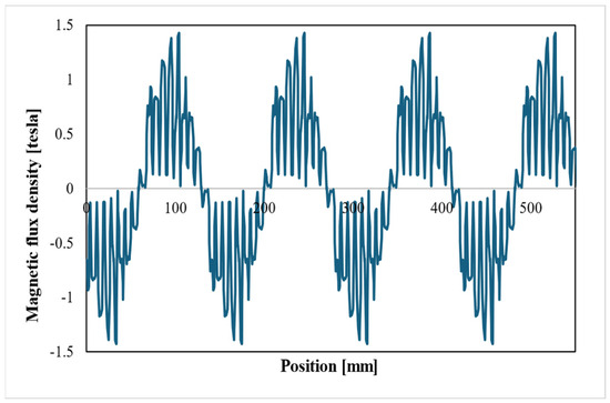
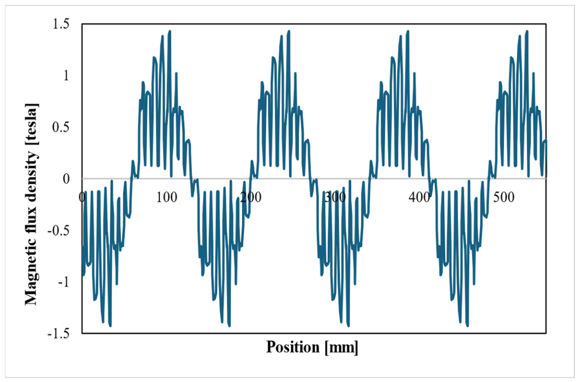
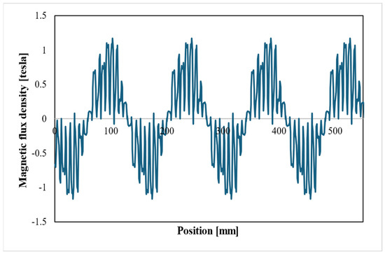
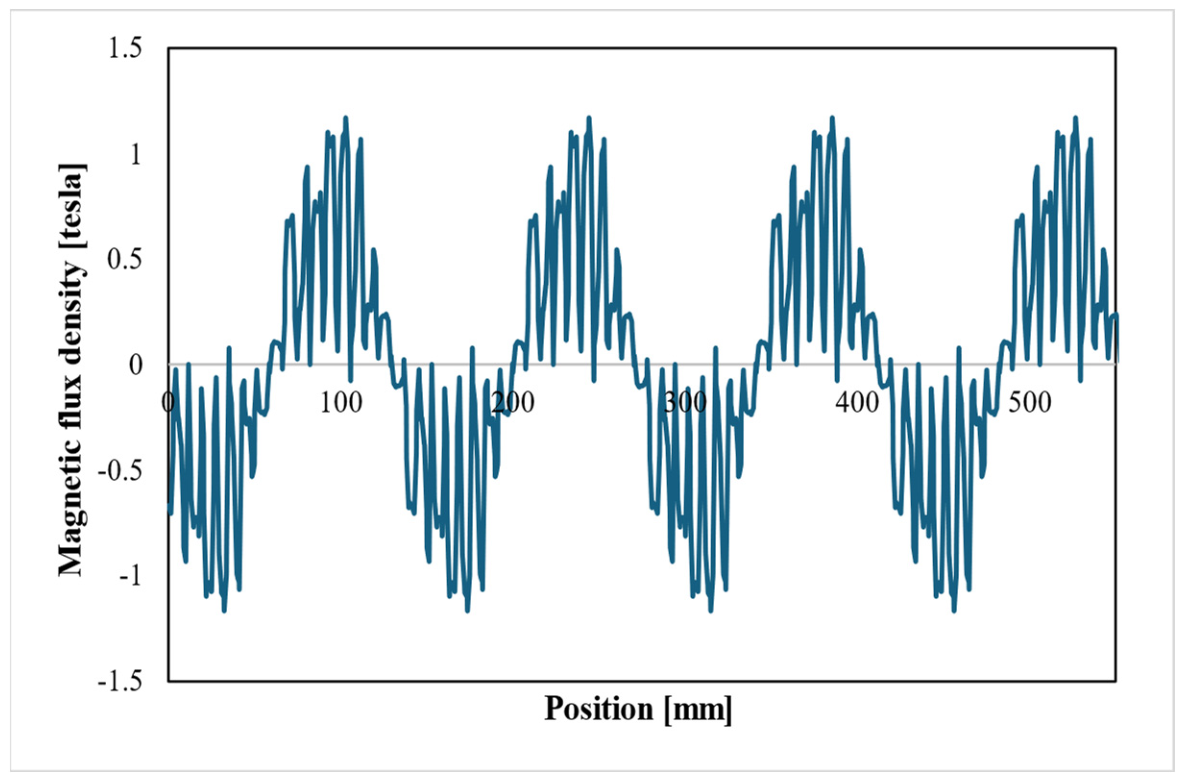
The air-gap magnetic flux density variations are presented in Figure 13 and Figure 14. These curves provide important information regarding the sinusoidal nature and harmonic content of the magnetic field distribution along the air gap. The smoothness of the air-gap flux density waveform is directly related to the stability of torque production and the level of torque ripple. When the curves of the IE2 and IE4 motors are evaluated together, it is observed that both motors provide the fundamental field distribution required for operation; however, the IE4 motor exhibits a more balanced air-gap flux profile. This can be regarded as a favorable indication in terms of a lower tendency toward local saturation and smoother torque production.
Figure 13.
Air-gap magnetic flux density variation in the IE2 induction motor.
Figure 14.
Air-gap magnetic flux density variation in the IE4 induction motor.
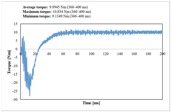
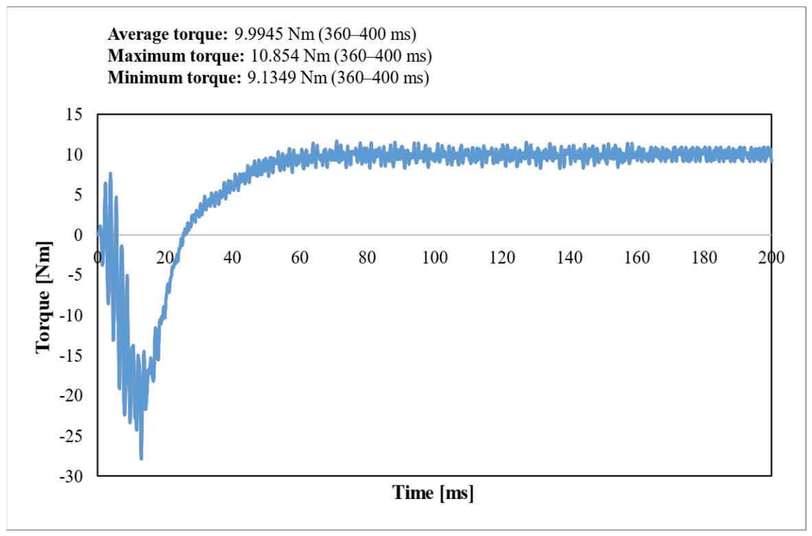
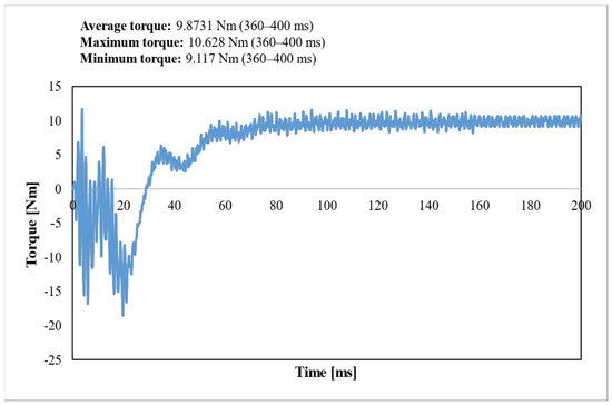
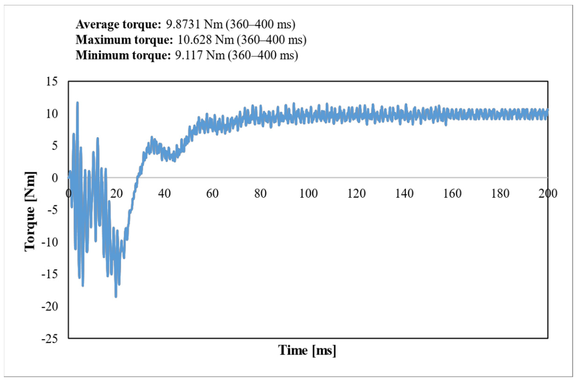
The steady-state torque ripple results for the IE2 and IE4 motors are presented in Figure 15 and Figure 16, respectively. Examination of the time variation in the electromagnetic torque shows that a certain fluctuation occurs around the average torque in both motors. This fluctuation is associated with slot effects, air-gap field harmonics, and the electromagnetic interaction between the rotor and stator. Nevertheless, the torque curve of the IE4 motor exhibits a more balanced character, and the torque ripple occurs at a lower level. This result is consistent with the smoother air-gap flux density waveform and the more controlled distribution of magnetic loading.
Figure 15.
Steady-state torque ripple of the IE2 induction motor.
Figure 16.
Steady-state torque ripple of the IE4 induction motor.
The average torque, torque ripple, current characteristics, and the maximum magnetic flux density values occurring in the critical regions of the investigated motors are presented in Table 3. The tabulated results quantitatively support the evaluations obtained from the visual analyses. In particular, the maximum flux density values observed in the stator and rotor teeth as well as in the yoke regions indicate that magnetic loading is higher in the IE2 motor. Similarly, the lower maximum magnetic flux density in the air gap of the IE4 motor points to a more balanced field distribution. Furthermore, when the torque ripple and current values are considered together, it can be seen that the IE4 motor structure exhibits a more stable and electromagnetically more controlled operating characteristic.
Table 3.
Main electromagnetic performance indicators of the IE2 and IE4 induction motors (adapted from [17] following CC-BY 4.0 licence).
Overall, the results of the electromagnetic field analysis reveal that the IE4 induction motor provides a more balanced magnetic flux distribution, a lower tendency toward local saturation, a smoother air-gap flux density profile, and more stable torque production compared with the IE2 motor. Therefore, the transition from IE2 to IE4 is not limited merely to an increase in the nominal efficiency label but also leads to a clear improvement in the fundamental operating characteristics of the motor through the enhancement of its electromagnetic field structure. These findings provide the physical basis for the numerical loss, efficiency, and torque–speed characteristics presented in the following section.
3.2. Numerical Performance Comparison
The numerical performance comparison of the IE2 and IE4 induction motors was carried out based on the efficiency–load curves, total loss and loss components, and torque–speed characteristics. Within this scope, the output obtained from the finite element analyses were used to evaluate the behaviors of both motors at the rated operating point and over an extended load range.
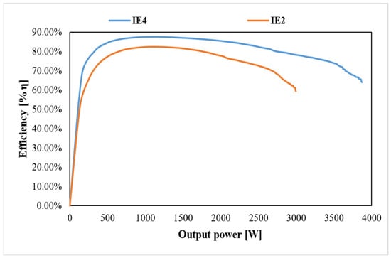
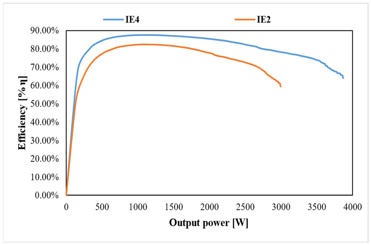
The efficiency–load curves of the IE2 and IE4 induction motors are presented in Figure 17. Examination of the curves shows that, in both motors, efficiency increases rapidly from the low-load region, reaches its maximum level in the medium-load region, and then tends to decrease again at higher output powers. This behavior is consistent with the expected characteristic trend of induction motors, arising from the combined variation in constant losses and load-dependent losses. Nevertheless, it is clearly observed that the IE4 motor provides a higher efficiency level than the IE2 motor over the entire operating range. In particular, around the rated operating point, the IE4 motor achieves higher energy conversion effectiveness with lower total losses.
Figure 17.
Efficiency–load curve of the IE2 and IE4 induction motor.
Although the rated power of the motors investigated in this study is 1.5 kW, the efficiency curves were evaluated over a wider output power range. Examination of the curves shows that, in the IE2 motor, the maximum efficiency is obtained approximately in the 1.0–1.5 kW range, and beyond this point, the efficiency gradually decreases as the output power increases. A similar trend is also observed in the IE4 motor; however, the maximum efficiency level is higher in this motor. In addition, the IE4 motor is seen to exhibit a more advantageous characteristic in the extended load region. This can be explained using M400 electrical steel with lower loss characteristics and the more appropriate distribution of electromagnetic loading enabled by the larger stack length.
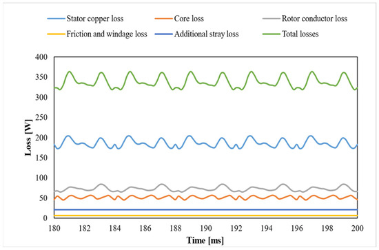
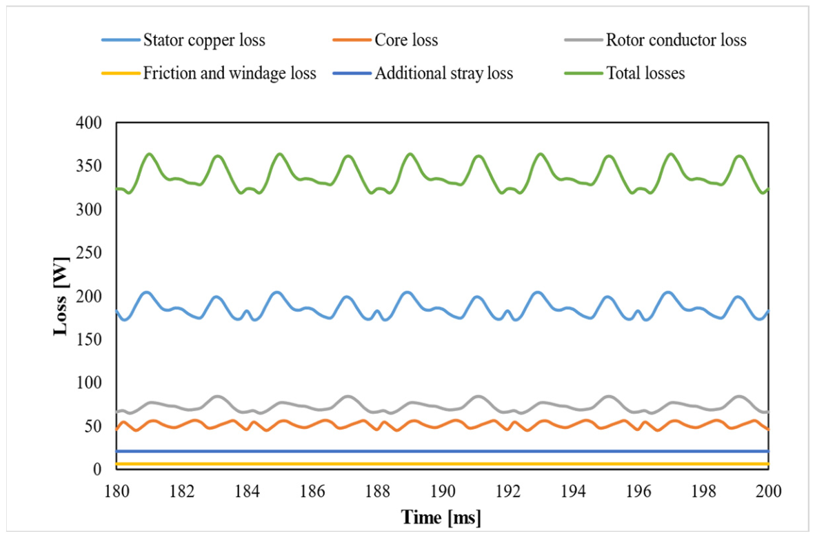
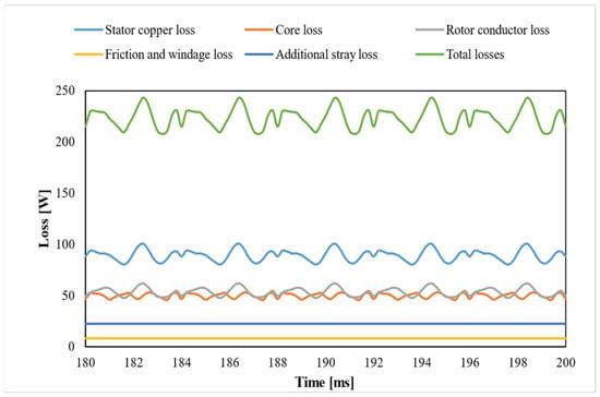
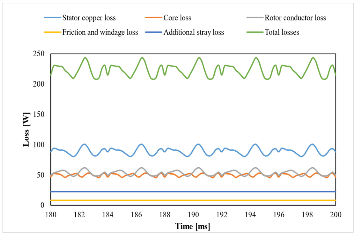
The total loss and loss components of the motors under the operating condition at 1.5 kW load are presented in Figure 18 and Figure 19, respectively. Examination of the loss distributions shows that, in both motors, the total loss exhibits a certain fluctuation over time, while its overall level is significantly lower in the IE4 motor than in the IE2 motor. Based on the graphs, it is understood that the total loss in the IE2 motor varies approximately within the range of 320–360 W, whereas in the IE4 motor this level decreases to approximately 210–245 W. This result indicates that the IE4 motor has a more advantageous structure in terms of total energy loss under rated load.
Figure 18.
Total losses and loss components of the IE2 induction motor.
Figure 19.
Total losses and loss components of the IE4 induction motor.
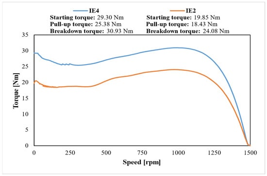
Another important component of the numerical performance comparison is the torque–speed characteristics. The torque–speed curves of the IE2 and IE4 motors are presented in Figure 20. From these curves, characteristic operating quantities such as starting torque, pull-up torque, and breakdown torque were obtained. Examination of the curves shows that, in both motors, in accordance with the classical behavior of induction motors, a high torque is produced at start-up, a limited decrease occurs in the low-speed region down to the pull-up torque, and then the torque increases again until it reaches the breakdown torque value. As the speed approaches synchronous speed, the torque decreases rapidly. This behavior indicates that the starting and loading characteristics of the motors are consistent with the expected electromechanical operating principle.
Figure 20.
Torque–speed curve of the IE2 and IE4 induction motor.
When the characteristic torque magnitudes are compared, the IE4 motor is seen to be more advantageous not only in terms of maximum torque capacity, but also in terms of the torque level in the starting and low-speed regions. This indicates that the IE4 motor has a stronger load-carrying characteristic and a higher torque reserve. In particular, the improvement in starting torque increases the load-taking capability of the motor during initial start-up, while the higher pull-up torque positively affects the critical operating behavior in the low-speed region. In addition, the higher breakdown torque level provides a safer and more stable operating characteristic against sudden load changes.
Overall evaluation of the numerical performance data given in Table 4 shows that the IE4 induction motor offers higher efficiency, lower total loss, lower copper and rotor losses, and a stronger torque–speed characteristic than the IE2 motor. These results demonstrate not only the achievement of a higher efficiency class, but also that the motor exhibits a more stable and advantageous performance over a wider operating range. Therefore, the transition from IE2 to IE4 should be regarded not merely as an increase in the nominal efficiency class, but also as a multidimensional improvement in terms of loss reduction, enhanced electromechanical performance, and increased effectiveness of energy utilization.
Table 4.
Numerical performance comparison of the IE2 and IE4 induction motors (adapted from [17] following CC-BY 4.0 licence).
3.3. Experimental Validation
This section presents a comparative evaluation of the prototype test results and the finite element analysis outputs for the IE2 and IE4 induction motors. By jointly considering the experimental measurements and the results obtained in the ANSYS Maxwell 2D environment, the capability of the developed electromagnetic model to represent actual motor behavior was examined. The comparison between the prototype test data and the FEM analysis results for the investigated motors is given in Table 5.
Table 5.
Comparison of prototype test results and FEM analysis results for the IE2 and IE4 induction motors (adapted from [17] following CC-BY 4.0 licence).
Examination of Table 5 shows that there is a high level of agreement between the experimental results and the analysis outputs, particularly in terms of torque, output power, efficiency, and speed values corresponding to the rated operating point. For both motors, the deviations in these quantities remain at quite low levels. This indicates that the developed numerical model successfully represents the electromechanical behavior of the motors under rated load. A generally acceptable level of agreement is also observed between the experimental and numerical results in terms of rated current and no-load current values. The differences observed in the power factor values are likewise limited, supporting that the model represents the electrical quantities with sufficient accuracy. In particular, the deviations in no-load current and power factor values can be related to the differences between the idealized magnetic material properties used in the simulation environment and the actual core behavior arising from manufacturing. The main reasons for these differences are considered to include lamination stacking quality, manufacturing-related variations in magnetization characteristics, and additional effects occurring in the actual magnetic circuit.
A generally good agreement was also obtained between the test and analysis results in terms of the loss components. The deviations obtained for the stator conductor loss, rotor conductor loss, and iron loss indicate that the model provides sufficient accuracy, particularly in the prediction of losses around the rated operating point. Overall, the loss segregation results demonstrate that the numerical model represents not only the general performance quantities but also the loss structure at a satisfactory level. Nevertheless, manufacturing-related material differences, the actual internal geometry of the rotor casting structure, two-dimensional model assumptions, and end effects may cause deviations to a certain extent.
When evaluated in terms of thermal conditions, very small differences were obtained between the winding resistance at 20 °C and the winding resistance under thermal steady-state conditions. This indicates that the conductor resistance and temperature approach used in the analysis model represent the real operating conditions of the prototype motors in a consistent manner. In addition, the fact that the thermal steady-state temperatures were taken as the same on both the test and analysis sides for both motors contributed to a more consistent basis for the model–test comparison.
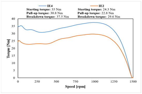
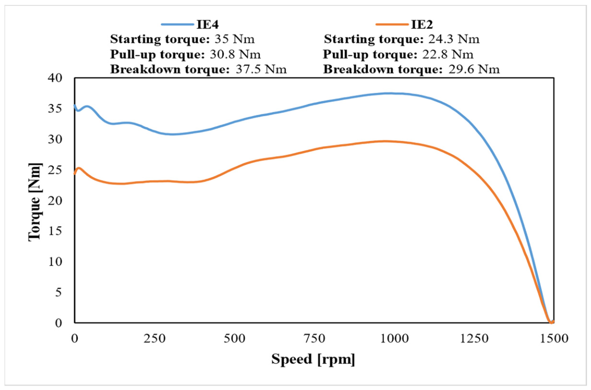
In contrast, higher deviations were observed in the starting torque, pull-up torque, and breakdown torque values given under the starting performance category compared with those at the rated operating point. This indicates that, although the model represents the rated operating point with high accuracy, capturing the transient electromechanical behavior in the starting and low-speed regions with the same level of accuracy is more difficult. As can also be seen from the experimental torque–speed curves presented in Figure 21, the behavior of the motors from start-up to the region close to synchronous speed is clearly revealed. These characteristic torque values are highly sensitive to rotor parameters, leakage reactance, current crowding effects, and manufacturing-related variations. In particular, the actual casting geometry of the rotor-bar structure, possible dimensional variations in the rotor slots and end rings, die-casting pressure, aluminum solidification and cooling conditions, manufacturing-related material property variations in aluminum, and contact conditions within the rotor cage may cause differences between the manufactured prototype and the numerical model. Moreover, at low speeds and high slip values, the rotor current distribution becomes more non-uniform, and leakage flux components become more dominant. In addition, stray flux components become more significant under high-slip and low-speed operating conditions. Since these flux paths cannot be fully represented in a two-dimensional finite element model, some discrepancies may occur between the numerical predictions and experimental measurements. However, their influence decreases as the motor approaches the rated operating point. Therefore, larger deviations are expected in the starting, pull-up, and breakdown torque values than in the rated operating-point quantities. Nevertheless, the agreement obtained at the rated operating point remains very high, indicating that the developed model is sufficiently accurate for evaluating the comparative steady-state performance of the IE2 and IE4 motors.
Figure 21.
Experimental torque–speed characteristic of the IE2 and IE4 induction motor.
In conclusion, the comparison between the prototype test results and the FEM analysis outputs shows that the developed electromagnetic model represents the IE2 and IE4 motors with sufficient accuracy, particularly in the rated operating region. Although higher deviations are observed in the characteristic torque quantities related to starting performance, this does not weaken the overall validation level of the model. On the contrary, it indicates that manufacturing-related and three-dimensional effects become more dominant in the low-speed region. The achieved level of agreement demonstrates that the modeling approach used in this study provides a reliable analytical basis and that the technical consequences of the transition from IE2 to IE4 can be evaluated consistently from both numerical and experimental perspectives.
3.4. Cost and Sustainability Results
In order to evaluate the technical performance differences between the IE2 and IE4 induction motors more comprehensively in terms of industrial applicability, annual energy consumption, operating cost, payback period, and carbon emission reduction potential are examined together in this section. In the economic assessment, a representative industrial operating scenario was taken as the basis, and the net annual operating time was accepted as 4488 h. For the unit electricity price, the applicable unit energy cost for industrial consumers in Türkiye was adopted, and a representative grid emission factor for Türkiye was used in the carbon emission calculations.
According to the prototype test results, for an output power of 1.5 kW, the input power of the IE2 motor was calculated as approximately 1.840 kW, whereas that of the IE4 motor was calculated as approximately 1.729 kW. Accordingly, the annual energy consumption was obtained as approximately 8260 kWh for the IE2 motor and approximately 7759 kWh for the IE4 motor. These results show that a transition to the IE4 motor can provide annual energy savings of approximately 501 kWh. Under the same operating scenario, the annual energy cost was calculated as approximately USD 1077.95 for the IE2 motor and approximately USD 1012.59 for the IE4 motor. Thus, it was found that the IE4 motor provides an annual operating cost advantage of approximately USD 65.35. The comparison of the main economic and environmental indicators for the IE2 and IE4 motors is presented in Table 6, while the principal gains achieved through the transition from IE2 to IE4 are presented in Table 7.
Table 6.
Cost and sustainability comparison of the IE2 and IE4 motors.
Table 7.
Benefits achieved by the transition from IE2 to IE4.
When evaluated in terms of initial investment cost, actual motor cost values are not reported for confidentiality reasons. Instead, the IE2 motor was represented by a normalized relative cost index of 100×, whereas the IE4 motor corresponded to a relative cost index of 126×, indicating approximately 26% higher relative initial motor cost. When this relative cost difference is considered together with the annual energy cost savings obtained under the selected operating scenario, the simple payback period calculated for the transition from IE2 to IE4 is obtained as approximately 0.81 years. This result shows that a higher-efficiency motor can provide advantages not only technically but also economically within a short period.
From a sustainability perspective, the annual reduction of approximately 501 kWh in energy consumption corresponds to an annual CO2 emission reduction of approximately 218.84 kg when evaluated together with the adopted grid emission factor. Therefore, the transition from IE2 to IE4 makes a meaningful contribution not only in terms of reducing energy costs, but also in terms of lowering indirect carbon emissions originating from industrial operations. In conclusion, the obtained findings reveal that, despite its higher initial investment cost, the IE4 motor is a more advantageous option for sustainable industrial applications due to its short payback period, lower annual operating cost, and lower carbon impact.
It should be noted that the economic and environmental results presented in this study are based on industrial electricity prices and grid emission factors applicable in Türkiye. Therefore, the calculated payback period and annual CO2 reduction may vary across different countries and regions. In many European countries, where industrial electricity prices are generally higher than those in Türkiye, shorter payback periods may be expected. Conversely, in regions where industrial electricity prices are lower, such as parts of the United States, the payback period may increase. From an environmental perspective, the CO2 reduction potential depends on the electricity generation mix of the region. Regions relying more heavily on fossil-fuel-based electricity generation may achieve greater emission reductions through the adoption of high-efficiency motors, whereas regions with a larger share of low-carbon electricity sources, such as renewable energy and nuclear power generation, may result in lower absolute CO2 savings for the same amount of energy saved. Nevertheless, the overall trend indicating the economic and environmental advantages of high-efficiency motors remains valid.
4. Discussion
The findings obtained in this study show that the difference between IE2- and IE4-class induction motors is not limited merely to their nominal efficiency values but also gives rise to multidimensional outcomes in terms of electromagnetic design, loss distribution, operating economics, and environmental impact. When the finite element analyses and prototype test results are evaluated together, the IE4 motor structure is seen to provide a more balanced magnetic flux distribution, a lower tendency toward local saturation, and more stable torque production. This indicates that achieving a higher efficiency class not only reduces energy consumption but also improves the fundamental electromechanical operating characteristics of the motor.
The numerical and experimental results showed that the IE4 motor has a clear advantage in terms of total losses. In particular, the reduction in stator conductor loss and rotor loss is among the main determinants of the overall efficiency improvement. Nevertheless, it is noteworthy that the iron loss could be kept under control in the IE4 motor structure despite the use of a larger stack length. This result shows that the use of low-loss M400 electrical steel and a more appropriate magnetic loading level should be considered together. Therefore, the transition to a higher efficiency class becomes possible not only by increasing the amount of active material, but also through material quality and electromagnetic optimization.
The results obtained in terms of torque–speed characteristics also provide important engineering implications. The stronger performance of the IE4 motor in terms of starting torque, pull-up torque, and breakdown torque indicates that it offers advantages not only in terms of energy efficiency, but also in terms of dynamic load-carrying capability. This may imply safer operation and higher load-carrying capacity, especially in industrial applications involving fans, pumps, compressors, and sudden load changes. In other words, the transition to the IE4 class is not merely a passive improvement that provides energy savings, but also an active design improvement that enhances functional performance.
In addition, prototype tests showed that the thermal steady-state temperature of the IE4 motor was lower than that of the IE2 motor. This can be associated with the reduction in total losses due to the higher efficiency and, in particular, with the decrease in conductor losses. Since the lifetime of insulation systems used in electrical motors decreases as operating temperature increases, a lower operating temperature reduces the aging rate of insulation materials and may contribute positively to the service life of the motor. Moreover, a lower temperature level can also be regarded as an important advantage supporting long-term operating performance in terms of bearings, grease structure, and overall mechanical reliability.
The economic assessment results showed that motors with higher efficiency classes can provide a return within a short period despite their higher relative initial cost. In this study, the simple payback period calculated for the IE4 motor, approximately 0.81 years, demonstrates that investments in high-efficiency motors have a strong economic justification, especially in continuously operating industrial equipment. The fact that motor purchasing decisions in industry are often made solely on the basis of initial investment cost leads to the neglect of the total cost of ownership approach. However, the obtained results clearly show that, over the operating lifetime, energy costs can offset the initial investment difference within a short period.
From a sustainability perspective, it was observed that the reduction in the annual energy consumption of the IE4 motor also resulted in a meaningful decrease in carbon emissions. Although the annual CO2 reduction obtained for a single motor may appear limited, it is clear that the total effect would be quite significant when it is considered that many motors operate simultaneously in industrial facilities. Therefore, the transition to high-efficiency motors is important not only in terms of reducing individual operating costs, but also in terms of national energy efficiency targets and carbon reduction strategies in industry.
Overall, the transition from IE2 to IE4 provides simultaneous gains in terms of technical performance improvement, energy efficiency, operating economics, and environmental impact. Therefore, upgrading standard induction motors used in existing industrial infrastructure to higher efficiency classes can be regarded as a feasible and strong strategy for the transition to sustainable production system.
5. Conclusions
In this study, the technical, economic, and environmental performances of IE2- and IE4-class induction motors with the same power and frame class were comparatively investigated through finite element analysis and prototype tests. The obtained findings showed that the transition from IE2 to IE4 provides significant advantages not only in terms of efficiency level, but also in terms of electromagnetic behavior, loss structure, thermal performance, operating economics, and sustainability.
The electromagnetic analysis results revealed that, compared with the IE2 motor, the IE4 motor offers a more balanced magnetic flux distribution, a lower tendency toward local saturation, a smoother air-gap field characteristic, and lower torque ripple. These results indicate that the transition to a higher efficiency class is not limited merely to the reduction in losses, but also improves the overall operating characteristics of the motor.
The prototype test results supported the accuracy of the developed numerical model. In particular, a high level of agreement was obtained between the finite element analysis and the experimental measurements at the rated operating point. This demonstrates that the adopted modeling approach provides a reliable method for the evaluation and development of industrial induction motor designs.
In terms of performance, the IE4 motor provided higher efficiency while exhibiting reductions in stator and rotor losses, and it also showed a stronger characteristic in terms of starting torque and breakdown torque. Thus, the IE4 design demonstrated superiority in both energy savings and load-carrying capability.
In addition, prototype tests showed that the operating temperature of the IE4 motor was lower than that of the IE2 motor. The lower operating temperature is a natural consequence of the reduction in total losses and may contribute positively to motor lifetime, particularly by reducing the aging rate of the winding insulation system. It also offers additional advantages in terms of the bearing system and overall operational reliability.
The economic assessment results showed that although the IE4 motor has a higher initial investment cost, it can recover this cost within a short period of approximately 0.81 years under the investigated operating scenario. This result indicates that not only the initial purchase cost, but also the total cost of ownership should be taken into account in motor selection.
From a sustainability perspective, the reduction in electricity consumption also led to a meaningful decrease in indirect CO2 emissions. Although this gain may appear limited at the scale of a single motor, it represents a significant environmental benefit when the widespread use of motors in industry is taken into consideration.
In conclusion, replacing existing IE2-class motors with IE4-class alternatives can be regarded as a technically feasible, economically rational, and environmentally beneficial strategy. In addition, owing to the lower operating temperature, it also offers further benefits in terms of motor lifetime, maintenance requirements, and long-term operational reliability.
Author Contributions
Conceptualization, S.S., Y.Ö. and İ.Ş.; methodology, S.S.; software, S.S.; validation, S.S.; formal analysis, S.S.; investigation, S.S.; resources, S.S.; writing—original draft preparation, S.S.; writing—review and editing, Y.Ö. and İ.Ş.; supervision, Y.Ö. and İ.Ş. All authors have read and agreed to the published version of the manuscript.
Funding
This research was funded by The Scientific and Technological Research Council of Türkiye (TÜBİTAK), grant number [1649B032403263]. The APC was funded by GAMAK.
Institutional Review Board Statement
Not applicable.
Informed Consent Statement
Not applicable.
Data Availability Statement
The original contributions presented in the study are included in the article, further inquiries can be directed to the corresponding author.
Acknowledgments
The authors sincerely thank the Scientific and Technological Research Council of Türkiye (TÜBİTAK) for financial support (Project number: 1649B032403263). The authors would like to acknowledge that this paper is submitted in partial fulfilment of the requirements for PhD degree at Yıldız Technical University. The authors sincerely thank GAMAK Electric Motors and its R&D team for their support in motor prototyping and experimental validation.
Conflicts of Interest
Author Sinan Suli is employed by GAMAK Electric Motors. The authors declare that GAMAK Electric Motors provided design and prototyping resources but did not influence the study.
References
- IEC 60034-30-1:2025; Rotating Electrical Machines—Part 30-1: Efficiency Classes of Line Operated AC Motors (IE Code). IEC: Geneva, Switzerland, 2025.
- IEC 60034-1:2026; Rotating Electrical Machines—Part 1: Rating and Performance. IEC: Geneva, Switzerland, 2026.
- IEC 60034-2-1:2024; Rotating Electrical Machines—Part 2-1: Standard Methods for Determining Losses and Efficiency from Tests (Excluding Machines for Traction Vehicles). IEC: Geneva, Switzerland, 2024.
- European Commission. Commission Regulation (EU) 2019/1781 of 1 October 2019 Laying Down Ecodesign Requirements for Electric Motors and Variable Speed Drives. In Official Journal of the European Union; European Commission: Brussels, Belgium, 2019; implementation stages effective from 1 July 2021 and 1 July 2023. [Google Scholar]
- International Energy Agency. Energy-Efficiency Policy Opportunities for Electric Motor-Driven Systems; IEA: Paris, France, 2011. [Google Scholar]
- United Nations Industrial Development Organization. Energy Efficiency in Electric Motor Systems; UNIDO: Vienna, Austria, 2017. [Google Scholar]
- de Souza, D.F.; Fong, J.; Hernandez, C.; Carmo, C. Environmental Impacts of Electric Motor Technologies: Life Cycle Approach Based on EuP Eco-Report. Environ. Impact Assess. Rev. 2025, 111, 107741. [Google Scholar]
- Azab, M. A Review of Recent Trends in High-Efficiency Induction Motor Drives. Vehicles 2025, 7, 15. [Google Scholar] [CrossRef] [Scilit]
- Heidarikani, K.; Dhakal, P.K.; Seebacher, R.; Muetze, A. Comparative Study of Steady-State Efficiency Maps and Time-Stepping Methods for Induction Motor Drive Cycle Performance Analysis. Energies 2025, 18, 5928. [Google Scholar] [CrossRef] [Scilit]
- Goman, V.; Prakht, V.; Kazakbaev, V.; Dmitrievskii, V. Comparative Study of Induction Motors of IE2, IE3 and IE4 Efficiency Classes in Pump Applications Taking into Account CO2 Emission Intensity. Appl. Sci. 2020, 10, 8536. [Google Scholar] [CrossRef] [Scilit]
- European Commission. Electric Motors—Energy Efficient Products; European Commission, Brussels, Belgium, Current Policy Assessment Page; EU-MORE Consortium, Accelerating Replacement of Old and Inefficient Electric Motors in Europe, EU-MORE Project Brochure; European Union: Brussels, Belgium, 2025. [Google Scholar]
- Bayraktar, Ş.; Turgut, Y. Experimental and Statistical Analysis of the Effects of Punching and Laser Cutting Methods on Induction Motor Efficiency and Total Magnetic Losses in Silicon Lamination Sheets. J. Magn. Magn. Mater. 2023, 572, 170599. [Google Scholar] [CrossRef] [Scilit]
- Gebauer, M.; Blejchař, T.; Brzobohatý, T.; Karásek, T.; Nevřela, M. Determination of Aerodynamic Losses of Electric Motors. Symmetry 2022, 14, 2399. [Google Scholar] [CrossRef] [Scilit]
- Sivaraju, S.S.; Senthilkumar, T.; Sankar, R.; Anuradha, T.; Usha, S.; Bin Musirin, I. Improving the Efficiency of Induction Motor Drive by Flux and Torque Control: A Hybrid LSE-RERNN Approach. ISA Trans. 2024, 147, 215–226. [Google Scholar] [CrossRef] [Scilit] [PubMed]
- Adamou, A.A.; Alaoui, C. Energy Efficiency Model-Based Digital Shadow for Induction Motors: Towards the Implementation of a Digital Twin. Eng. Sci. Technol. Int. J. 2023, 44, 101469. [Google Scholar] [CrossRef] [Scilit]
- Paramo-Balsa, P.; Roldan-Fernandez, J.M.; Semião, J.; Burgos-Payan, M. Estimation of Power Output and Efficiency of Induction Motors: A New Non-Intrusive Approach. Sensors 2025, 25, 754. [Google Scholar] [CrossRef] [Scilit] [PubMed]
- Suli, S.; Öner, Y.; Şenol, İ. Design of SynRM and PMaSynRM Using a Common Industrial Stator Platform: A New Design Methodology for Transition from Industrial Applications to Electric Vehicles. Eng. Sci. Technol. Int. J. 2025, 71, 102204. [Google Scholar] [CrossRef] [Scilit]
- Liu, M.; Chen, L.; Sheng, X.; Yang, Y.; Yu, F.; Li, Y.; Yuan, X.; Li, Y.; Wang, Q.; Ma, Q. Dynamic Simulation of Life Cycle Environmental Benefits of Remanufacturing Asynchronous Motors to Permanent Magnet Synchronous Motors. J. Clean. Prod. 2023, 426, 138932. [Google Scholar] [CrossRef] [Scilit]


Disclaimer/Publisher’s Note: The statements, opinions and data contained in all publications are solely those of the individual author(s) and contributor(s) and not of MDPI and/or the editor(s). MDPI and/or the editor(s) disclaim responsibility for any injury to people or property resulting from any ideas, methods, instructions or products referred to in the content. |
© 2026 by the authors. Licensee MDPI, Basel, Switzerland. This article is an open access article distributed under the terms and conditions of the Creative Commons Attribution (CC BY) license.