


Featured Application
The methodology presented in this study may be applied to the development of low-voltage power distribution systems for Formula Student vehicles and other weight-constrained electric vehicle applications. It can be used both for direct system design and for simulation-supported optimization of conductor sizing, wiring-harness routing, protection strategies, and auxiliary battery integration. By accounting for load profiles, resistive losses, thermal behavior, and regulatory constraints, the proposed approach supports the development of lightweight, electrically robust, and application-tailored LV architectures.
Abstract
Designing low-voltage (LV) power distribution systems for mass-sensitive electric vehicles involves several unresolved technical challenges, including parasitic losses, excessive mass of commercial off-the-shelf distribution units, and difficulties in isolating thermal phenomena during vehicle operation. In dynamic racing conditions, temperature measurements of LV components are strongly influenced by external heat sources such as traction batteries, motors, and inverters, complicating accurate assessment of conductor self-heating and distribution losses. This work presents a load-driven methodology for the specification, implementation, and validation of LV architectures, demonstrated using a Formula Student electric race car. The proposed approach combines harness current mapping, resistive loss modeling, and component-level topology optimization to support the development of lightweight and electrically robust systems. Within this framework, a mass-optimized programmable solid-state power distribution unit (PDU), an auxiliary battery system with a battery management system (BMS), and an optimized LV wiring harness were developed and experimentally validated through controlled subsystem tests and in-vehicle operation. The proposed methodology enabled reduction in PDU mass by 40–80% relative to commercially available solutions while maintaining programmable protection, integrated current sensing, and stable thermal operation under representative racing loads. This reduction was achieved through load-driven conductor sizing, application-specific protection threshold optimization, and elimination of redundant protection and interconnection hardware. The developed PDU achieved a mass of 155 g with measured channel resistances of 40–70 m. The auxiliary battery pack exhibited an average internal resistance of 64.2 m at a total mass of 2190 g, while the optimized harness demonstrated resistivity in the range of 14.72–33.98 m/m. Experimental validation confirmed stable operation below critical thermal limits under both nominal and off-nominal load conditions. The obtained results demonstrate that the proposed methodology enables measurable reductions in both system mass and resistive power losses through application-specific optimization of the LV architecture. However, the presented approach is primarily suited for motorsport and other highly mass-constrained applications, where reduced packaging volume, efficiency, and weight justify the increased design complexity and lower universality compared to commercial off-the-shelf solutions.
1. Introduction
Formula Student [1] is an international engineering design competition in which university teams design, manufacture, and validate formula-style race cars under strict technical and safety regulations [2]. The competition emphasizes system-level integration, cost efficiency, and regulatory compliance. Similar optimization-driven sizing methodologies have also been investigated in other energy storage applications, where system efficiency and operating constraints directly influence energy storage sizing and overall system performance [3].
Prior studies on Formula Student electric vehicle design have addressed various aspects of system architecture [4], energy assessment [5], powertrain configurations [6,7], drivetrain implementation [8], and complete vehicle builds [9,10].
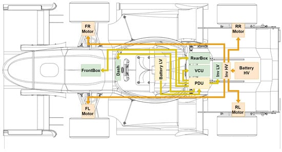
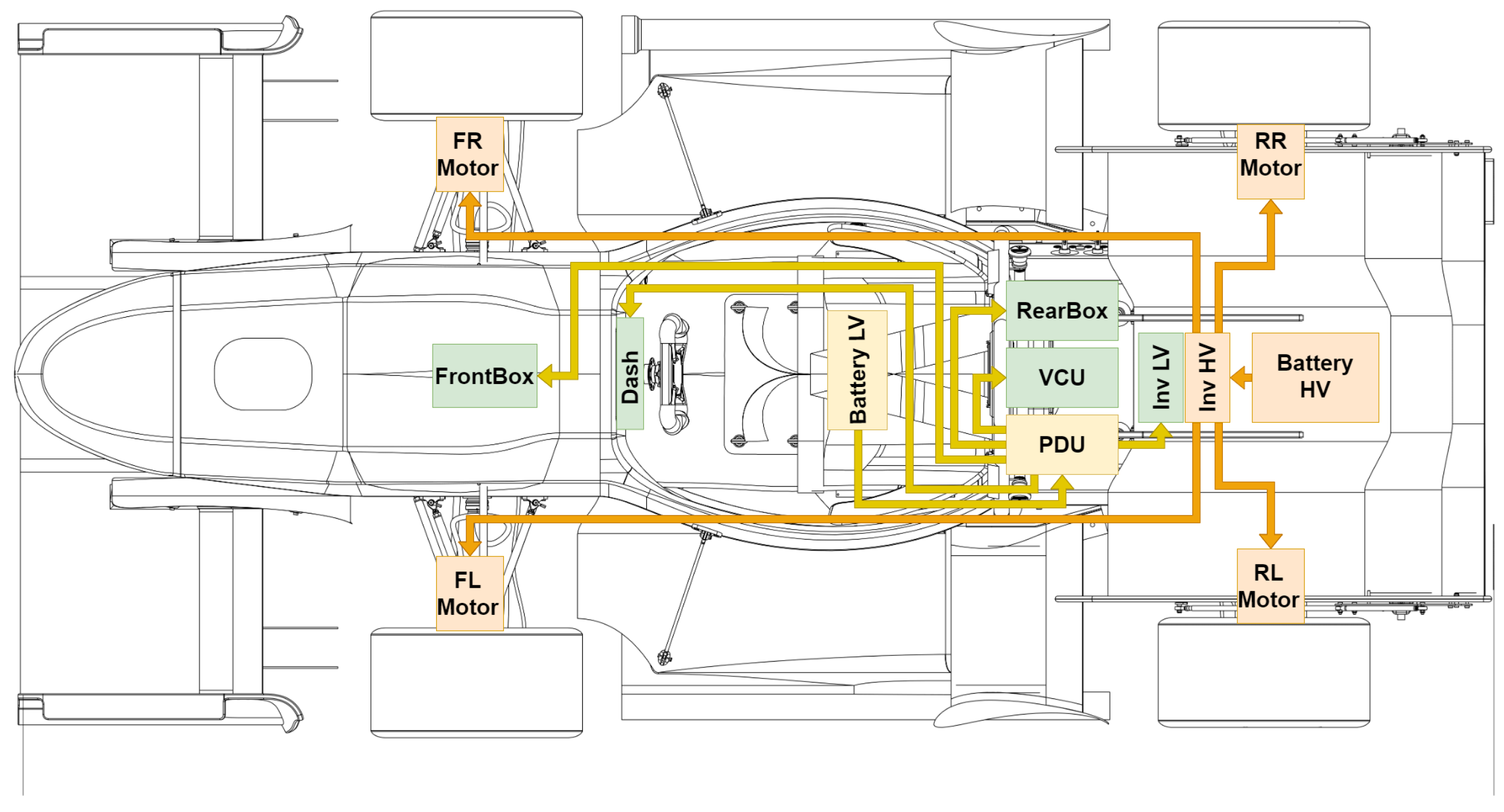
The electrical architecture of an electric Formula Student vehicle is divided into two primary domains, the high-voltage Tractive System (TS) and the Grounded Low Voltage (GLV) subsystem, as illustrated in Figure 1. The TS includes the traction battery, inverters, and electric motors responsible for propulsion. In contrast, the GLV supplies all auxiliary and control electronics, including the Vehicle Control Unit (VCU), sensors, telemetry modules [11], battery management system (BMS) low-voltage interface, and safety-critical circuits. Within this architecture, the GLV is responsible for powering control, sensing, communication, and safety systems. A key element of this subsystem is the power distribution system, which ensures controlled energy delivery to all loads. Its design directly influences system reliability, electrical efficiency, and vehicle dynamic performance. Additionally, in accordance with Formula Student regulations, galvanic isolation between the TS and GLV domains must be maintained (Rule EV 4.3 [2]), introducing strict design constraints. A typical LV power distribution architecture consists of three main components: an auxiliary energy source, a power distribution unit (PDU), and an electrical wiring harness. The auxiliary battery provides stable voltage supply, the PDU manages current distribution and protection, and the wiring harness ensures physical interconnection between subsystems. Depending on the implementation, distribution may be based on conventional fuse-based systems or solid-state switching architectures, each offering different trade-offs in terms of efficiency, mass, and flexibility. The functional roles of these components are strongly interdependent. The auxiliary battery must maintain voltage stability under dynamic load conditions, the PDU must provide reliable and selective protection while enabling current monitoring, and the wiring harness must minimize resistive losses while maintaining thermal and mechanical robustness. Several design challenges arise in LV systems for high-performance electric vehicles. These include cumulative resistive losses () in conductors, increased thermal loading of components, and additional mass associated with conservative conductor sizing or redundant protection hardware. As a result, suboptimal LV design can reduce overall system efficiency and negatively impact vehicle performance. In particular, commercial off-the-shelf (COTS) PDUs, although reliable, are typically designed for general automotive applications and introduce excess mass, redundant protection elements, and limited flexibility in system-level integration. From a regulatory perspective, Formula Student rules impose additional constraints on LV system design, including voltage limits, isolation requirements, and mandatory safety mechanisms [2]. These constraints necessitate careful integration of electrical, thermal, and mechanical design aspects. From a market perspective, several commercial PDU and LV distribution solutions are available. To better position the proposed design, selected commercial motorsport Power Distribution Modules (PDM/PMU) are compared in Table 1, including key parameters such as mass, number of outputs, and total current capability.
Figure 1.
System topology overview: The PDU acts as the central hub, distributing power to the FrontBox, RearBox, VCU, and motors, while maintaining interface with the LV Battery.
Table 1.
Comparison of selected commercial PDM/PMU units including inputs and current capacity.
It should be noted that the commercial units listed in Table 1 are not fully equivalent in terms of enclosure design, diagnostic functionality, current sensing capability, environmental protection, and protection strategy. Therefore, the comparison should be interpreted primarily as a mass, channel-count, and current-capability benchmark rather than as a complete functional or efficiency benchmark.
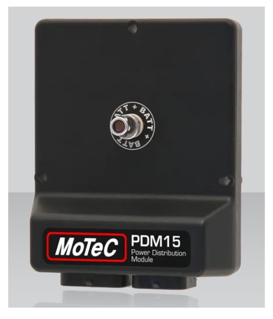
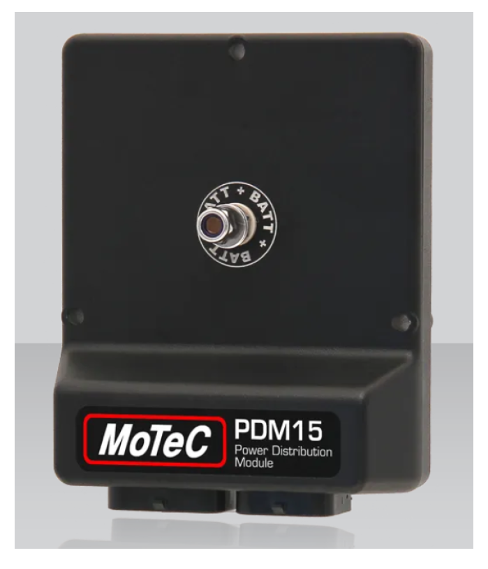
As shown in Table 1, commercially available PDM units typically weigh between 260 g and 760 g for systems offering 8–32 outputs. Even relatively compact solutions, such as the MoTeC PDM15 or ECUMaster PMU-16, exceed 250 g. In contrast, the proposed system achieves a mass of only 155 g while providing 16 output channels, resulting in a significantly improved mass-to-channel ratio. This is particularly advantageous in Formula Student applications, where minimizing vehicle mass is critical. An example of a commercial solution is shown in Figure 2. Commercial PDM units typically weigh between 260 and 760 g for systems offering 8–32 outputs. The proposed architecture, weighing only 155 g for 16 channels, achieves a 40–80% mass reduction compared to industry standards. While lightweight options like the CARTEK module exist (80 g), they provide only four channels and limited functionality, making them unsuitable for complex programmable requirements.
Figure 2.
MoTeC PDM15 Power Distribution Module—example of a commercial motorsport power distribution unit. The device integrates multiple solid-state outputs in a compact enclosure and is widely used in automotive and racing applications. Source: MoTeC official website [12].
Beyond mass reduction, energy efficiency is a parameter of critical importance that is frequently omitted from the technical documentation of commercial PDM solutions. The lack of publicly available efficiency data for PDM units makes precise energy loss comparisons difficult, representing a significant information gap in the design process. This work demonstrates that the proposed architecture achieves an efficiency of 95.981%.
Highlighting this parameter is essential, as it directly dictates the sizing and mass of the auxiliary energy storage system. Assuming a standard system voltage of 24 V and an average load of 5 A, the average power demand of the connected subsystems is 120 W. Comparing this result with a hypothetical efficiency of 90%—often found in universal power conversion units—illustrates the scale of energy savings over a one-hour period, corresponding to the duration of the Endurance event and its preparations:
- PDU Power Losses: At 95.98% efficiency, the power dissipated as heat within the device is approximately 4.82 W. For a unit with 90% efficiency, these losses increase to 12.00 W.
- Energy Balance: Over one hour of operation, a lower-efficiency system would waste an additional 7.18 Wh of energy solely as waste heat.
- Battery Impact: To compensate for these losses at 24 V, the battery pack would require an additional 0.30 Ah of capacity. Given the developed 10.98 Ah pack, this equates to a necessary increase in energy resources of approximately 2.7%.
The high efficiency of the proposed system enables the elimination of redundant cells and the associated “mass penalty” caused by thermal dissipation. This facilitated the implementation of a compact 2190 g battery pack. In the context of Formula Student, where every second on track depends on the power-to-weight ratio, this efficiency gap represents a tangible design advantage, ensuring thermal stability and maximum energy density for the entire low-voltage architecture.
However, their universal design limits their applicability in weight-sensitive racing environments, where the optimization of mass, efficiency, and integration is paramount. For instance, while commercial modules with comparable channel counts, such as the MoTeC PDM32 [13] () and the AiM PDM32 (), impose a significant mass penalty on the vehicle’s overall weight budget, the architecture proposed in this study weighs only . This represents a mass reduction of over compared to current industry standards [14,15] while maintaining the required operational functionality.
Despite the critical nature of LV systems, existing research has largely prioritized traction battery design, inverter efficiency, and high-voltage protection. A comprehensive experimental framework that quantitatively addresses the benefits of precise power distribution sizing remains largely absent in the literature. This paper fills this gap by proposing an architecture specifically optimized for the load profiles of a four-motor electric race car. This targeted approach enables the elimination of redundant circuitry and heavy enclosures typical of general-purpose devices, which—as demonstrated in the subsequent validation section—results in minimized power losses and voltage drops alongside a drastic reduction in system mass.
The main contributions of this work are as follows:
- A load-driven LV specification methodology incorporating harness current mapping and resistive loss modeling,
- A mass-optimized programmable solid-state PDU topology,
- Experimental validation of LV harness losses, thermal performance, and compliance with Formula Student 2026 regulations [2].
2. Materials and Methods
The low-voltage (LV) distribution architecture is implemented as an integrated subsystem designed for a high-performance Formula Student electric vehicle equipped with four in-wheel motors. In such configurations, the LV system must support distributed loads with dynamic current profiles, including motor controllers, sensors, telemetry modules, and safety-critical electronics. Therefore, the design process must address not only electrical performance, but also mass efficiency, thermal behavior, and compliance with Formula Student regulations.
In accordance with Rule EV 4.3 [2], the LV domain is galvanically isolated from the Tractive System (TS), preventing fault propagation from the high-voltage network into control and safety electronics. This requirement directly influences system topology, component selection, and protection strategies.
The adopted design methodology follows a load-driven approach, in which electrical load characterization forms the basis for system dimensioning. Current demand profiles are used to define conductor sizing, component selection, and protection thresholds, enabling optimization of the trade-off between mass, efficiency, and thermal performance.
2.1. Design Objectives and Constraint Formulation
To ensure design robustness and reproducibility, the development of the Low Voltage (LV) distribution system was guided by specific performance targets and explicit electrical constraints. Rather than treating system parameters solely as outcomes of the optimization process, fixed boundaries were established for current capacity, voltage stability, and overall efficiency to satisfy regulatory requirements and ensure system-level reliability.
2.1.1. Load Mapping and Current Constraints
The current demand profiles were established by aggregating the maximum power ratings derived from the technical specifications of commercial components. For custom-designed printed circuit boards (PCBs), a conservative current consumption limit of A per module was adopted. This methodology enabled the creation of a comprehensive load map representing worst-case operating conditions, ensuring the PDM is appropriately sized to handle peak simultaneous demand across all subsystems.
2.1.2. Voltage Drop and Efficiency Targets
In the design process of the low-voltage (LV) power distribution system, the permissible voltage drop () was not treated merely as a secondary outcome, but rather as a key optimization criterion dictating the system architecture. An absolute and non-negotiable safety limit for the voltage drop was established at of the nominal supply voltage (corresponding to approximately V for a 24 V system). The selection of this limit stems from the necessity to find an optimal compromise between power stability and the requirement for a drastic reduction in vehicle mass. Distributed logic subsystems (e.g., VCU, telemetry) operate at logic levels of 5 V or V and are supplied by local step-down converters. These converters require a strictly defined input voltage margin (dropout voltage). Limiting the voltage drop on the main bus to guarantees that even during severe transient states—such as current spikes during the startup of high-performance coolant pumps—the network voltage will not fall below the under-voltage lockout (UVLO) threshold. This effectively eliminates the risk of critical vehicle logic resets during driving. Simultaneously, attempting to achieve lower voltage drops would necessitate the use of significantly thicker conductors, which would negate the goal of reducing the total system mass by compared to conventional solutions.
The validity of the adopted assumptions and the high effectiveness of the designed architecture were verified through an analysis of the power characteristics. For a single channel operating under nominal load, the following parameters were recorded:
The internal power consumption of the PDM logic (), resulting from the current differential between input and output, is merely:
To assess the system’s capability under extreme conditions, a four-channel scenario () was tested. With a total input current of A and an input power of W, the system delivered output power W to the loads. This results in an excellent overall system efficiency:
Under these maximum load conditions, the measured voltage drop was V (approximately ). This result is highly satisfactory, as it unequivocally proves that the mass-optimized conductor cross-sections allow the system to remain safely below the critical threshold. It confirms that the significant reduction in copper usage was executed correctly, providing the system with excellent energy density, operational integrity, and minimal thermal dissipation.
Thermal considerations were strictly aligned with the safety requirements of the Formula Student regulations. Although the rules do not explicitly limit the temperatures of low-voltage wiring as strictly as HV circuits, a maximum operating temperature of 85 °C was imposed in the design. This is an intentionally conservative assumption serving as an additional safety buffer against the degradation of contacts and insulation, despite the fact that standard coatings of the selected conductors permit continuous operation at temperatures up to 200 °C according to manufacturer datasheets. The system also had to strictly comply with Rules EV 3.2.1 and EV 3.2.2 [2], which prohibit the tripping threshold of overcurrent protection devices from exceeding the current rating of the protected components.
2.2. Power Distribution Unit (PDU) as the Central Protection and Control Element
Design Methodology
The Power Distribution Unit (PDU) is a highly integrated modular system designed to achieve a competitive mass of 155 g. Beyond mass reduction, its primary contribution to the LV architecture is high electrical efficiency resulting from the use of ultra-low-resistance smart switches, which minimize internal power losses and heat dissipation. Reduced distribution losses directly influence the overall vehicle design by enabling more precise sizing of the auxiliary battery pack and reducing the need for redundant energy reserves. Consequently, the system achieves lower overall mass while simultaneously limiting thermal stress on surrounding electronics. Furthermore, programmable current sensing across all 16 channels provides a substantially higher level of protection flexibility compared to conventional fuse-based architectures.
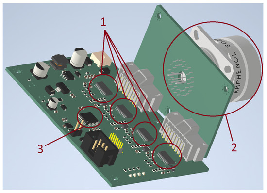
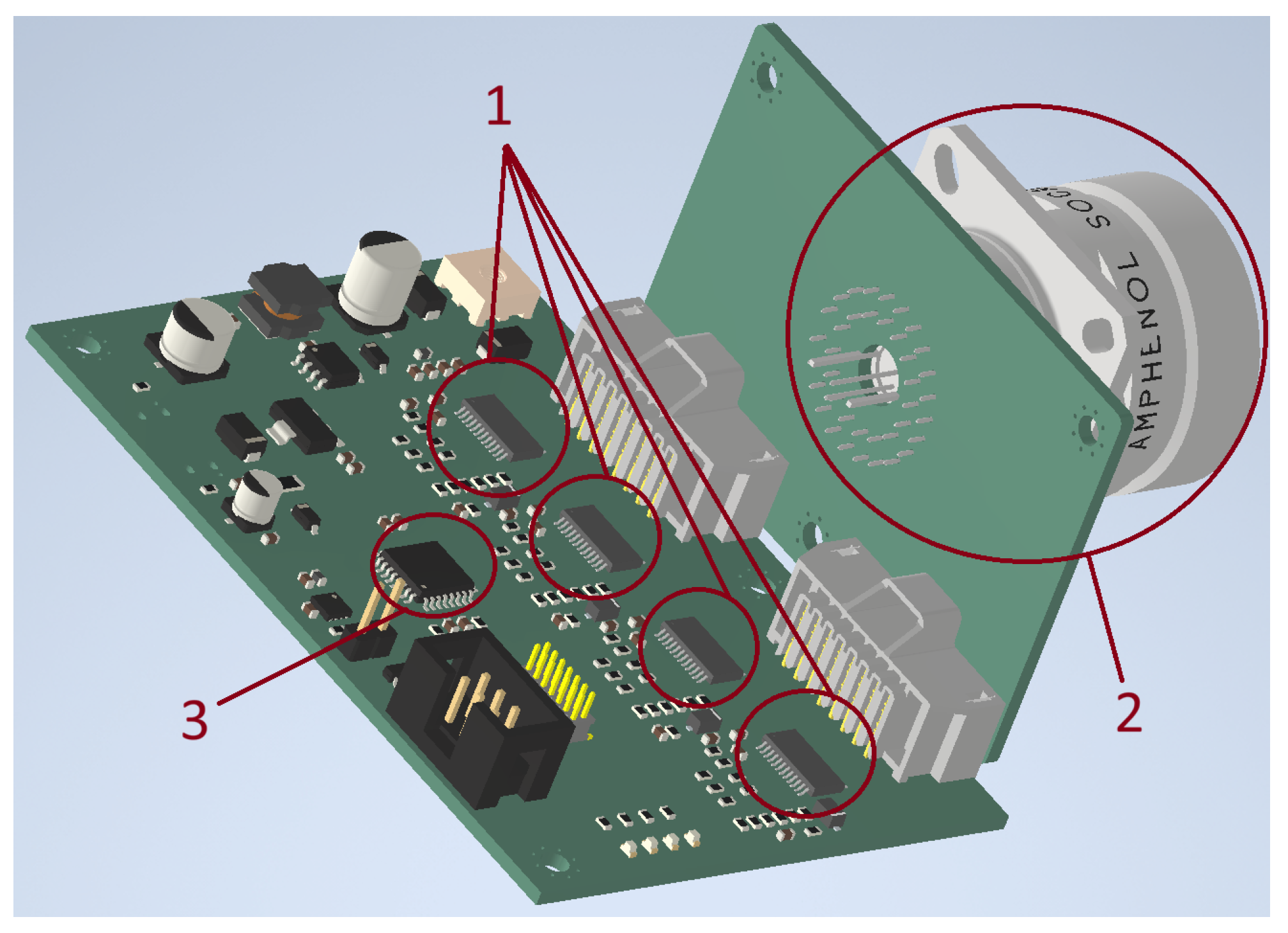
The system architecture was directly driven by functional and packaging constraints. In particular, the separation into two mechanically coupled printed circuit boards—a control board and a power interconnection board (see Figure 3)—was introduced to decouple signal processing from high-current routing. This approach improves electromagnetic compatibility, simplifies routing of high-current paths, and enables more efficient utilization of the available installation space within the vehicle. Additionally, the angled arrangement of the boards facilitates compact packaging and optimized cable routing.
Figure 3.
Assembled Power Distribution Unit (PDU) in vehicle-ready configuration: (1) programmable high-side smart switches (BTS72220) connected via SPI in a daisy-chain configuration; (2) high-current connector interfacing with power distribution paths; (3) STM microcontroller acting as the main control unit, communicating with the switches via the SPI interface.
Mass and system complexity optimization were key design drivers. During the early design stage, commercially available relay-based and transistor-based power distribution solutions were analyzed to identify architectures suitable for Formula Student applications. In parallel, individual load profiles and current-carrying requirements were determined for each subsystem connected to the output channels. Based on this evaluation, BTS72220 smart switching integrated circuits were selected and combined with the programmable capabilities of the STM-based control platform.
Conventional automotive PDM solutions typically require separate protection devices, current sensing circuits, relay stages, and extensive interconnect structures. In the proposed design, these functions were integrated within programmable BTS72220 smart switches, significantly reducing the number of discrete components and PCB area. Additional mass reduction was achieved through the use of an SPI daisy-chain communication structure, which minimized the number of required signal lines and enabled the use of a smaller and less complex microcontroller. Furthermore, the separation between control and power PCBs enabled optimization of copper distribution and conductor geometry specifically for the expected load conditions of the Formula Student vehicle.
From a reliability and protection perspective, integrated current sensing within each channel enables real-time monitoring of load conditions and implementation of software-defined protection strategies. Unlike conventional melting fuses, which are affected by thermal inertia and parameter variability, the applied solid-state architecture enables repeatable and rapid response to overcurrent conditions. This approach improves protection of both sensitive control electronics and the wiring harness against overload-related thermal stress, which is particularly important in distributed LV systems operating under racing conditions.
The mechanical structure of the PDU was designed to ensure adequate thermal performance and structural rigidity under racing conditions. High-current paths were reinforced using additional copper structures to reduce resistive losses and improve heat dissipation. The complete assembly was enclosed within a protective housing, providing resistance against vibration, contamination, and mechanical stress.
Compared to commercial off-the-shelf solutions designed for a broad range of automotive applications, the proposed PDU was optimized specifically for the operating conditions of a Formula Student vehicle. This application-oriented approach eliminated redundant protection hardware and unnecessary enclosure mass, resulting in a total system mass of only 155 g while maintaining the required functionality.
Control and diagnostic functionality is implemented on an STM32 microcontroller (Figure 3, item 3), which configures the switching devices, acquires current measurement data via SPI, and communicating system status over the CAN bus [16], following typical embedded automotive control architectures [17].
2.3. Battery Pack and BMS Architecture
2.3.1. Battery Pack Design Methodology and BMS Architecture
The auxiliary low-voltage battery serves as the primary power source for all non-tractive subsystems, including control functions (ECU, inverter control interfaces, supervisory electronics), telemetry and communication modules (CAN-based logging and wireless data transmission devices), cooling-related loads (pumps and fans), sensing subsystems (temperature, current, and position sensors), and safety-related electronics (shutdown control and monitoring circuits). Consequently, the battery pack and its Battery Management System (BMS) [18,19,20,21] were designed to ensure stable operation of distributed low-voltage (LV) loads under both steady-state and transient conditions. A custom BMS architecture was implemented, integrating cell-level monitoring and regulation-compliant safety functions while maintaining low system mass. Passive balancing was selected due to its simplicity and low weight [22], and the measurement architecture was designed to provide sufficient voltage accuracy and temperature monitoring to meet Formula Student technical inspection requirements and in-vehicle operation.
2.3.2. Energy Specification Methodology and Auxiliary Power Architecture Implementation
The design process of the low-voltage power distribution system was based on an analytical load-driven methodology, where the energy storage output parameters are a direct function of the aggregated dynamic load profile of all subsystems. Replacing traditional component selection with precise current mapping enabled a critical reduction of the vehicle’s total mass.
To ensure endurance reliability, the battery capacity was derived from a comprehensive power balance, identifying the average current demand () across all functional domains under racing conditions. Table 2 provides the detailed decomposition of the GLV consumption.
Table 2.
Detailed average current demand of low-voltage systems.
With a total system demand of , a baseline of is required for the mandatory operational window, covering the 22 km Endurance event and pre-start procedures. To maintain voltage stability and avoid deep discharge during peak transient loads, a target capacity of was adopted, providing a safety margin.
A nominal standard (nominally in a 6S configuration) was prioritized over a conventional architecture as a strategic weight-management decision. By doubling the system voltage, the current required to deliver the same power is halved, which results in a 75% reduction in resistive power losses () within the wiring harness. This efficiency gain is critical, as it enables the safe transition from heavy, large-gauge wires to ultra-lightweight 22–26 AWG conductors, directly minimizing the copper mass. Furthermore, the potential ensures that step-down converters for logic-level power (, ) operate with a stable overhead, eliminating the risk of system resets during high-power transient events.
Based on these requirements, a 6S2P configuration using Samsung SDI CC5493F101 [23] lithium-ion cells (21,700 format) was selected. This configuration provides a nominal voltage of ~21.8 V and a total capacity of 10.98 Ah, satisfying both voltage and energy requirements while maintaining compact packaging. The parallel configuration enables sufficient current capability, while the series configuration ensures compatibility with the selected voltage level. The battery configuration and capacity were determined following established Formula Student sizing methodologies [24,25,26].
The maximum continuous discharge current of the selected cells is 2C, corresponding to approximately 21.3 A for the full pack, while peak current capability reaches up to 3C (approximately 32 A). These values were considered sufficient to support both steady-state operation and transient load conditions.
The mechanical design was driven by strict mass and packaging constraints typical for Formula Student vehicles. The adopted form factor enables efficient integration within the vehicle structure while minimizing volume and mass. The enclosure design follows safety requirements, including the use of flame-retardant materials (UL94 V-0), electrical insulation of ungrounded terminals, and provision for controlled gas venting.
The BMS architecture was designed in accordance with Formula Student Rule T 11.7 [2], requiring continuous cell-voltage monitoring and automatic shutdown if voltage limits are exceeded for longer than 500 ms. Temperature monitoring covers more than 30% of the cells using NTC thermistors, and the system disconnects the battery if any cell exceeds its safe temperature limit (typically 60 °C) for longer than 1 s. Additionally, all measurements can be accessed via an external interface, and individual measurement lines can be disconnected during technical inspection.
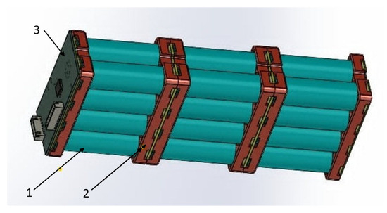
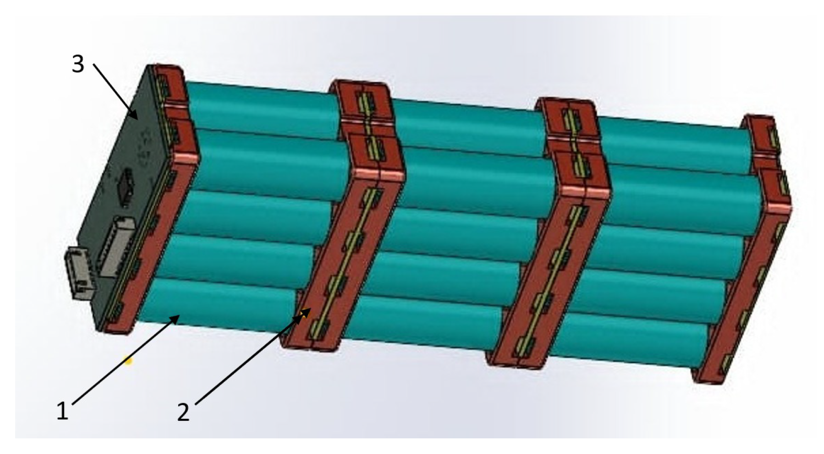
The spatial integration and 3D CAD assembly of the custom low-voltage battery pack with its integrated BMS architecture are illustrated in Figure 4.
Figure 4.
CAD model of the physical implementation of the low-voltage system (LVS) battery pack: 1—Samsung INR21700-50S lithium-ion cells (Samsung SDI Co., Ltd., Suwon, Republic of Korea) lithium-ion cells arranged in a 6S2P configuration; 2—dedicated cell holders/sockets integrated into the enclosure, ensuring mechanical immobilization of the cells, together with spot-welded nickel interconnects and parallel hardware fuse paths; 3—custom BMS printed circuit board integrated with the battery enclosure.
2.3.3. Battery System Validation and Experimental Testing
Communication with other vehicle systems takes place via the CAN bus operating at 1 Mb/s. A diagnostic interface is additionally provided through USB in accordance with the regulation requirement [2].
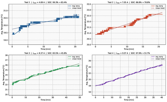
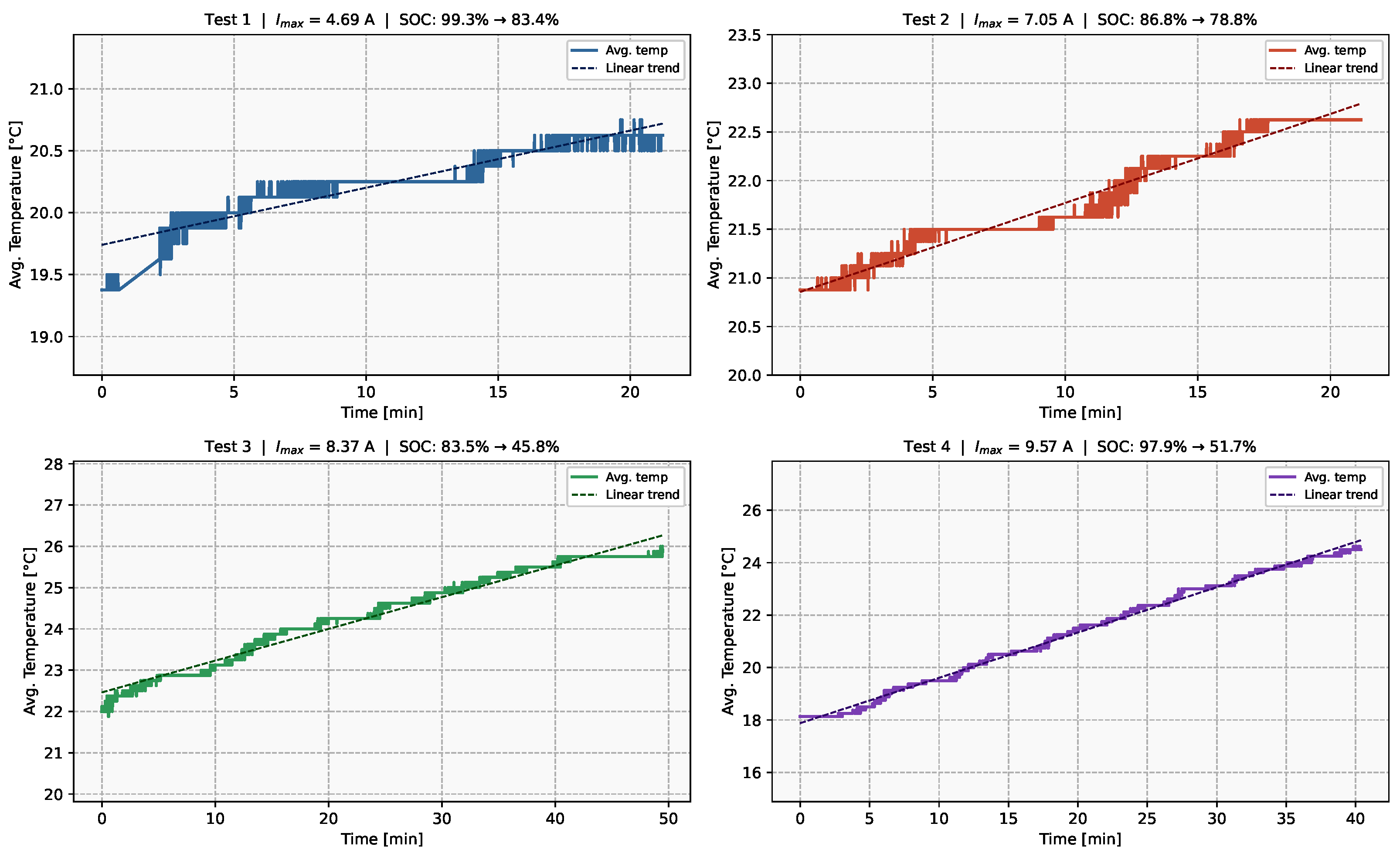
System validation comprised three stages: (I) controlled battery discharge tests performed under predefined load profiles, (II) charging-process verification, and (III) in-vehicle operational verification during driving. The discharge-test stage is summarized in Figure 5 and includes four representative scenarios used to assess the thermal and electrical behavior of the auxiliary battery pack under both nominal and off-nominal operating conditions.
Figure 5.
Average cell temperature and current draw during battery discharge tests. Test 1: Discharge simulation under realistic driving conditions at nominal load. Tests 2–4 represent discharge profiles evaluated under elevated temperature conditions beyond the assumed design envelope, using different durations, enabling assessment of system robustness under increased thermal stress.
The curves presented in Figure 5 support the experimental validation of the battery system’s thermal and electrical safety margins. Test 1 represents a nominal operating scenario corresponding to typical vehicle activity under expected load conditions, verifying stable pack operation. In this case, cell temperatures stabilized at 21–23 °C at an ambient temperature of 18 °C, while the current draw did not exceed 6 A, indicating that under normal vehicle operation, the system remains in a state of high thermal stability far below any critical thresholds.
To further demonstrate system robustness, Tests 2–4 were introduced as off-nominal discharge scenarios specifically designed to evaluate the system beyond its assumed operating envelope. These stress tests assessed the sensitivity of the battery pack to underestimated or overestimated load profiles under elevated thermal conditions. By demonstrating that cell temperatures remain strictly controlled even when peak current is increased significantly (reaching 9.57 A in Test 4), Figure 5 provides visual evidence that the 60 °C safety limit governed by the BMS remains unthreatened even under increased electrical stress.
In addition to these controlled discharge tests, charging-process verification and real-world driving tests were used to validate communication stability and overall system functionality. Ultimately, the validation procedure confirmed three main design assumptions: the system is inherently stable under nominal load, robust enough to handle severe off-nominal stress without thermal runaway, and maintains flawless diagnostic and communication performance during vehicle integration.
2.4. Optimized Electrical Harness
2.4.1. Harness Design Requirements
The electrical harness forms the physical interconnection layer of the low-voltage distribution architecture, linking the auxiliary battery, Power Distribution Unit (PDU), and distributed electronic subsystems across the vehicle. In a Formula Student racing car, the wiring harness must satisfy strict constraints related to mass reduction, mechanical robustness, and electrical efficiency [27]. As part of the GLV (Grounded Low Voltage) system, it serves as the backbone of the PDU-based power distribution network.
The primary design requirements were defined based on the operating conditions of the vehicle. The harness must withstand continuous vibration, dynamic mechanical loading, and repeated bending cycles typical for racing applications. These conditions introduce failure mechanisms such as conductor fatigue, fretting, and degradation of electrical contact interfaces [28].
From an electrical perspective, the system must ensure reliable power delivery while minimizing resistive losses. This requires appropriate conductor sizing based on actual load conditions rather than conservative nominal assumptions. Additionally, electromagnetic compatibility (EMC) must be ensured, particularly for communication lines such as CAN, which are sensitive to noise generated by switching devices and motor controllers [29].
A key requirement was also the reduction of system mass. In Formula Student applications, excessive copper usage directly impacts vehicle performance; therefore, conductor dimensions must be optimized to balance electrical performance and weight.
Furthermore, the harness must ensure high connection reliability under dynamic conditions. Connector interfaces must maintain stable electrical contact despite vibration and current-induced stresses, which are known to cause fretting and increased contact resistance [30].
2.4.2. Harness Physical Implementation
To meet the defined requirements, the harness was implemented using a concentric cable topology, in which individual conductors are arranged radially around a central mechanical core and enclosed within a common protective sleeve. Compared to conventional parallel cable bundles [31], this configuration improves mechanical durability under dynamic loading conditions by providing more uniform stress distribution and reducing relative motion between conductors.
The internal structure of the harness was organized according to electrical function. High-current supply lines, low-current control signals, and communication interfaces were separated into distinct radial layers. Sensitive communication lines, such as CAN, were implemented as twisted pairs to improve noise immunity and ensure stable data transmission [29].
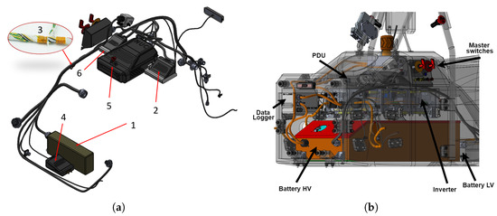
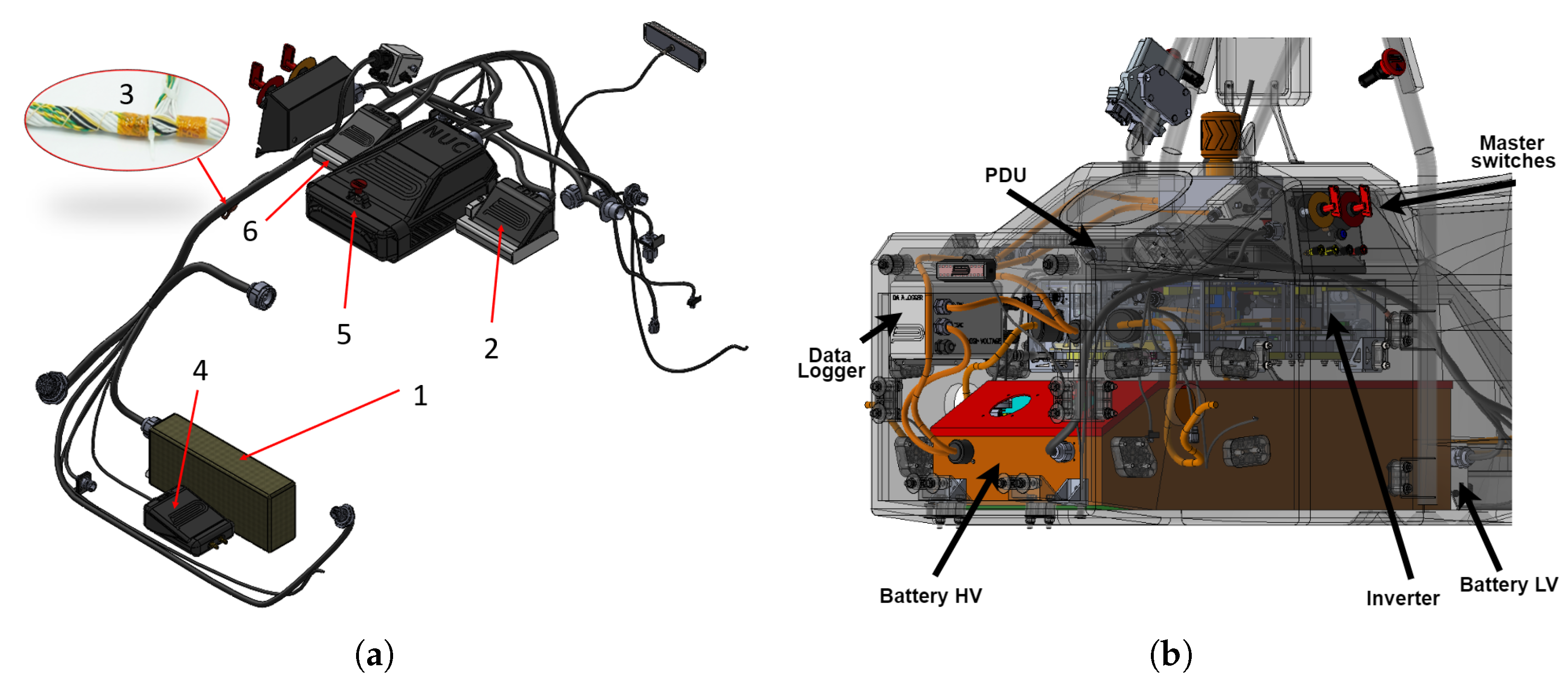
Conductor cross-sections were selected based on current demand profiles initially derived from component datasheets and subsequently refined using measurements obtained from controlled bench testing of individual subsystems. The final selection of conductor sizes was therefore based on a trade-off between current capacity, voltage-drop margin, thermal robustness, and harness mass. In particular, conductors were not oversized solely according to conservative nominal assumptions, but were matched to the expected load of each branch. This approach reduced unnecessary copper mass while maintaining acceptable electrical performance for the connected subsystems. This load-based sizing approach enabled reduction in unnecessary conductor mass while maintaining safe current density and thermal performance [32]. Cable routing, within the vehicle, as illustrated in Figure 6, was optimized to minimize total conductor length, following a shortest-path principle, while satisfying the packaging constraints requiring all components to be placed within their designated zones of the vehicle monocoque.
Figure 6.
Overview of the LV system components and vehicle integration: (a) Diagram of primary subsystems: (1) low-voltage battery pack with custom BMS, (2) Power Distribution Unit (PDU), and (3) optimized electrical harness, (4) GNSS, (5) VCU (Vehicle Control Unit), (6) RearBox—rear telemetry board; (b) Internal packaging view showing the placement of energy storage and distribution units within the vehicle’s protective envelope.
High-reliability connectors with positive locking mechanisms were used at all subsystem interfaces to ensure stable electrical connections under vibration. The selection of connector systems was guided by their proven performance in harsh environments, where resistance to mechanical stress and electrical degradation is critical.
Studies on electrical connector reliability indicate that vibration and current-induced stresses are the dominant factors affecting contact lifetime, leading to degradation mechanisms such as fretting wear and increased contact resistance [30]. Therefore, high-reliability circular connectors, such as MIL-DTL-38999 [33] and 8STA [34], were selected due to their ability to maintain stable electrical contact under dynamic loading conditions typical for motorsport applications.
Mechanical strain relief was implemented using adhesive-lined heat-shrink tubing and braided protective sleeves, providing both mechanical stabilization and protection against abrasion and environmental exposure.
2.4.3. Harness Testing
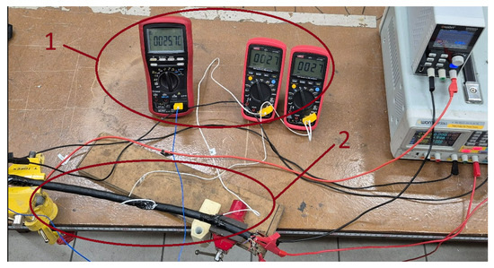
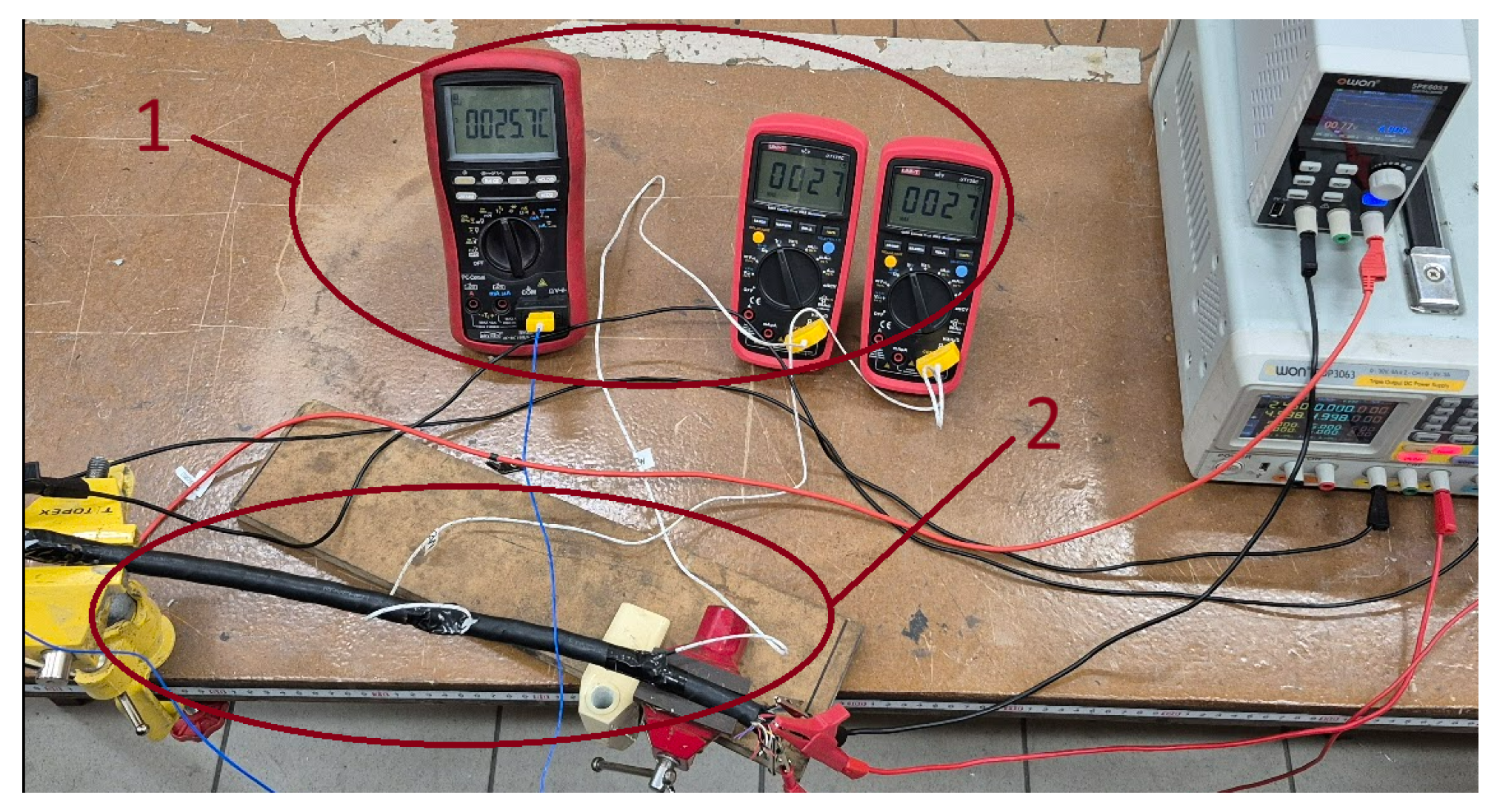
The assembled harness was verified through electrical continuity testing and insulation resistance measurements to confirm stable performance under representative operational conditions. As part of the validation process, temperature measurements marked as (1) in Figure 7 were conducted under simulated load conditions increased by 20% relative to nominal racing operation. This load case was selected as a conservative verification scenario for the harness thermal behaviour. The purpose of the test was to confirm that the selected conductor sizes and routing did not lead to excessive temperature rise under loads exceeding the expected nominal racing demand.
Figure 7.
Test stand for measuring temperature inside a concentric twisted harness: (1) measured temperatures; (2) section of the electrical harness with mounted temperature sensors.
The resulting harness provides a lightweight and mechanically resilient electrical infrastructure that supports efficient energy distribution while maintaining low resistive losses and high reliability in the demanding environment of a Formula Student racing vehicle. The validation procedure was intended to verify the electrical and thermal robustness of the harness under controlled but representative operating conditions. It should be noted that the applied test conditions do not fully reproduce all dynamic effects occurring during racing operation, such as simultaneous vibration, repeated bending, thermal cycling, and transient current profiles. Therefore, the presented validation confirms continuity, insulation integrity, and thermal stability under conservative controlled loading, while full dynamic vehicle-level durability remains a subject for further testing.
3. Results
3.1. Electrical Performance and Mass of the PDU
3.1.1. Physical Implementation Results
The total mass of the developed PDU was measured to be 155 g. For comparison, commercially available automotive power distribution modules, such as motorsport-grade PDUs, typically exhibit masses in the range of 260 g to over 760 g, as shown in Table 1.
This represents a mass reduction of approximately 40–80%, which is a significant advantage in weight-constrained applications such as Formula Student electric vehicles.
3.1.2. Experimental Validation
The electrical performance of the Power Distribution Unit (PDU) was experimentally evaluated using a channel-level validation procedure conducted under controlled load conditions. Each output channel was individually tested using power resistors reproducing the expected operating currents, while current measurements were obtained using the integrated sensing functionality of the BTS72220 devices during steady-state operation.
Measurement accuracy was verified by independently measuring the voltage drop across the load using a laboratory power supply, enabling calculation of the reference current. Sensor readings were compared with reference values, and a linear approximation was applied to compensate for measurement error and offset. Based on this calibration, individual shutdown thresholds were adjusted to ensure that current limits consistent with conductor current-carrying capacity were not exceeded.
Following calibration, the on-state resistance of individual PDU output channels was experimentally assessed. The measured channel resistance ranged from 40 m to 70 m, indicating stable electrical performance of the implemented low-voltage distribution paths. For comparison, the datasheet value of the BTS72220 high-side smart switch indicates a typical on-state resistance in the range of 5.5 m to 13.5 m, with a maximum value of approximately 22 m [35]. The higher resistance observed in the present study is attributed to additional contributions from the complete current path, including PCB traces, interconnect structures, and connector interfaces. Consequently, the measured resistance reflects the performance of the assembled PDU channel rather than the semiconductor switch alone.
These results confirm that, in compact low-voltage power distribution systems, channel resistance should be evaluated at the system level, since the physical implementation of the distribution path has a substantial influence on final electrical performance. In combination with the measured PDU mass reported in Section 3.1.1, the obtained resistance values indicate that the proposed design achieves a favorable mass–electrical performance trade-off for weight-constrained Formula Student applications.
3.2. Electrical and Thermal Validation of the Auxiliary Battery Pack
3.2.1. Physical Implementation Results
The internal resistance of the battery pack was determined analytically based on the selected cell configuration and interconnect design. The pack employs a 6S2P configuration with Samsung INR21700-50S lithium-ion cells (Samsung SDI Co., Ltd., Suwon, Republic of Korea) in the 21,700 format. According to the cell datasheet [23], the maximum initial internal impedance is 18 m per cell (measured at AC 1 kHz after standard charge at 23 °C). For two cells connected in parallel, this yields a group resistance of 9 m; with six groups in series, the total cell contribution is 54 m.
The interconnect strips are made of copper (, cross-sectional area , resistivity ). The resistance of a single strip of length L is given by
Five series strips (, each), six parallel strips (, each), and two terminal leads (, each) contribute a combined strip resistance of approximately 21 m, yielding a theoretical total pack resistance of ≈75 .
In addition to its electrical characteristics, the battery pack achieves a total mass of approximately 2190 g, which is competitive for a 6S2P lithium-ion auxiliary pack in the Formula Student class. This outcome results from the selection of the 21,700 cell format, a lightweight Kevlar-composite enclosure, and 3D-printed UL94 V-0 rated cell holders.
3.2.2. Experimental Validation
Experimental verification was performed across three measurement series at varying states of charge (SoC) and load currents. The results are summarised in Table 3.
Table 3.
Summary of measured internal resistance across three test series.
The overall mean measured pack internal resistance is 64.2 m, in good agreement with the theoretical estimate of ≈. The deviation is primarily due to the fact that the datasheet specifies a worst-case maximum of 18 m, whereas typical cells exhibit 12–15 m, reducing the expected contribution by 9–18 m.
Additional discrepancies may result from contact resistance at weld joints [36], which was not included in the analytical model.
3.3. Experimental Evaluation of Harness Resistance
3.3.1. Physical Implementation Results
The electrical wiring harness was designed based on a load-driven approach, with conductor dimensions and lengths selected to minimize resistive losses while maintaining mechanical robustness and low overall mass.
3.3.2. Experimental Validation
The resistance of individual conductors in the wiring harness was determined experimentally. All measurements were performed at a current of approximately 3.00 A.
The measured voltage drops ranged from 199.05 mV to 412.29 mV, corresponding to calculated resistances between 66.26 m and 137.25 m.
After applying a correction for the measurement system resistance, the effective conductor resistances —defined as the resistance with the contribution of the measurement leads and fixtures subtracted—were obtained in the range of 12.05 m to 83.04 m.
The measured resistance per unit length varies from 14.72 m/m to 33.98 m/m, which remains significantly lower than the catalogue value of , as detailed in Table 4.
Table 4.
Measured resistance of wiring harness conductors (all wires, 1–4, have the same cross-section and material).
The resistance per unit length was calculated as follows:
where is the measured resistance after subtracting the resistance of the measurement leads and fixtures, and L is the conductor length. The highest measured voltage drop was at a current of . Referred to the nominal auxiliary battery voltage of , this corresponds to a maximum relative voltage drop :
For a system level, the same voltage drop corresponds to approximately . Both values remain below the adopted practical design margin of approximately , indicating that the selected conductor sizing provides an acceptable compromise between voltage stability and harness mass reduction. The complete validation results are summarised in Table 5.
Table 5.
Summary of the electrical harness validation criteria.
4. Discussion
The obtained results support the main objective of this work, namely, the development and experimental verification of a load-driven low-voltage (LV) distribution architecture for a weight-constrained Formula Student electric vehicle. The proposed system integrates an auxiliary battery pack, a programmable solid-state Power Distribution Unit (PDU), and a mass-optimized wiring harness, enabling the simultaneous consideration of electrical performance, mass efficiency, thermal behavior, and regulatory compliance. A key outcome of the study is the validation of the proposed load-driven specification methodology. Current demand characterization was used to guide conductor sizing, protection-threshold definition, and component selection. The harness results, with measured resistance per unit length in the range of 14.72–33.98 m/m, confirm that this approach can reduce copper mass while maintaining acceptable voltage drop and thermal performance. At the same time, the results show that such optimization remains constrained by thermal limits, allowable voltage drop, and mechanical robustness. Another important finding concerns the mass-optimized programmable PDU topology. The measured channel resistance of 40–70 m is higher than the datasheet on-state resistance of the switching devices, which is expected because the measured value represents the complete current path, including PCB traces, connectors, and interconnect structures. This highlights that compact LV power distribution systems should be evaluated at the system level, rather than only through component datasheet values. For the auxiliary battery pack, the measured mean internal resistance (64.2 m) was lower than the theoretical estimate of approximately 75 m. This difference is mainly attributed to the conservative nature of datasheet-based maximum cell resistance values. Therefore, the adopted analytical model may be regarded as a safe upper-bound approximation suitable for design-stage sizing, while still requiring experimental verification. Overall, the results indicate that the proposed architecture provides a favorable mass–performance trade-off for Formula Student applications. The main value of the work lies not only in the implemented hardware, but also in the demonstrated methodology linking current mapping, resistive loss modeling, topology selection, and experimental validation. The study also has several limitations. The analytical battery model does not include contact resistance at weld joints [36], the comparison with commercial solutions is limited mainly to mass and functional integration, and the harness validation was performed under controlled rather than fully dynamic operating conditions. Full quantitative validation of the complete LV power distribution system under racing conditions is difficult due to practical measurement limitations. During vehicle operation, the LV system is exposed to highly dynamic and simultaneous electrical, thermal, and mechanical loads. The current demand of individual loads varies with the operating state of pumps, fans, control units, sensors, telemetry devices, safety-related circuits, and other auxiliary subsystems. At the same time, the PDU manages multiple output channels, the auxiliary battery responds to transient current demand, and CAN-based communication links operate continuously between distributed electronic modules. This creates a large number of transient operating conditions that are difficult to isolate and evaluate independently during track operation. Another important limitation is the restricted packaging space available in a Formula Student vehicle. Installing extensive measurement equipment at multiple points of the LV system could affect harness routing, component placement, mass distribution, thermal conditions, and potentially the reliability of the system itself. Therefore, the measurement setup required for full in-vehicle characterization could modify the operating conditions of the system being evaluated. Thermal measurements during vehicle operation are also affected by several external heat sources, including the traction battery, inverters, motors, cooling system components, high-voltage cables, the PDU, and power electronics. As a result, it is difficult to separate the temperature rise caused by the self-heating of individual LV components from the thermal influence of surrounding subsystems. For these reasons, the validation procedure was intentionally based mainly on controlled subsystem tests and integration tests, where the electrical load, measurement points, and thermal environment could be defined more clearly. This approach provides repeatable and interpretable data for electrical performance, voltage drop, thermal behaviour, protection functionality, communication stability, and system integration. Nevertheless, the obtained results should be interpreted as controlled electrical, thermal, and functional validation of the proposed LV architecture rather than complete dynamic durability verification under all racing conditions. Accordingly, the presented work should be interpreted as a quantitatively validated engineering case study rather than a universal benchmark for all LV architectures. Future work should include more detailed modeling of contact resistances, broader benchmarking against commercial motorsport PDU solutions, and validation under dynamic operating conditions. Nevertheless, the present results demonstrate that the proposed load-driven design framework can serve as a practical basis for lightweight, electrically robust, and regulation-compliant LV systems in Formula Student vehicles and other mass-sensitive electric vehicle applications.
5. Conclusions
This study presents a load-driven design framework for the development of a low-voltage power distribution architecture for a Formula Student electric vehicle. The proposed approach integrates harness current mapping, resistive loss modeling, and component-level topology optimization to support the design of lightweight and electrically robust LV systems. Based on this framework, a programmable Power Distribution Unit (PDU), an auxiliary battery subsystem, and an optimized wiring harness were developed and experimentally validated. The obtained results confirmed that the adopted design methodology enables mass reduction while maintaining acceptable electrical and thermal performance, as well as compliance with Formula Student 2026 regulations. For the complete LV power distribution system, the results confirmed the effectiveness of the proposed load-driven design methodology for the investigated Formula Student vehicle. However, the measured values should be interpreted as vehicle-specific results, since LV system performance depends on load distribution, component placement, PDU topology, auxiliary battery configuration, harness routing, connector selection, packaging constraints, and regulatory requirements. Therefore, the presented results should be treated as a validation of the proposed design procedure rather than as a universal benchmark for all LV power distribution systems. The findings indicate that the proposed approach may serve as a practical basis for the development of lightweight, regulation-compliant, and application-tailored LV systems in Formula Student vehicles and other mass-sensitive electric vehicle applications.
Author Contributions
Conceptualization, M.B., T.M. and J.M.; methodology, M.B., T.M. and J.M.; software, M.B., T.M. and J.M.; validation, M.B., T.M. and J.M.; formal analysis, M.B., T.M., J.M. and G.W.Ś.; investigation, M.B., T.M. and J.M.; resources, M.B., T.M., J.M. and G.W.Ś.; data curation, M.B., T.M., J.M. and G.W.Ś.; writing—original draft preparation, M.B., T.M., J.M. and G.W.Ś.; writing—review and editing, M.B., T.M., J.M. and G.W.Ś.; visualization, M.B. and T.M.; supervision, J.M. and G.W.Ś. project administration, G.W.Ś.; funding acquisition, G.W.Ś. All authors have read and agreed to the published version of the manuscript.
Funding
This work was supported by the Polish Ministry of Science and Higher Education under the program ‘Studenckie koła naukowe tworzą innowacje’, grant no. SKN/SP/630899/2025.
Institutional Review Board Statement
Not applicable.
Informed Consent Statement
Not applicable.
Data Availability Statement
The original contributions presented in this study are included in the article. Further inquiries can be directed to the corresponding author.
Conflicts of Interest
The authors declare no conflicts of interest.
Abbreviations
The following abbreviations are used in this manuscript:
| 4WD | Four-Wheel Drive |
| ADC | Analog-to-Digital Converter |
| BMS | Battery Management System |
| CAN | Controller Area Network |
| COTS | Commercial Off-The-Shelf |
| DC | Direct Current |
| EMI | Electromagnetic Interference |
| EV | Electric Vehicle |
| GLV | Grounded Low Voltage |
| GNSS | Global Navigation Satellite System |
| LV | Low-voltage |
| N-MOSFET | N-channel Metal-Oxide-Semiconductor Field-Effect Transistor |
| NTC | Negative Temperature Coefficient |
| PDU | Power Distribution Unit |
| PUT | Poznan University of Technology |
| SoC | State of Charge |
| SPI | Serial Peripheral Interface |
| TS | Tractive System |
| USB | Universal Serial Bus |
| VCU | Vehicle Control Unit |
References
- Formula Student Official Website. Available online: https://www.formulastudent.com (accessed on 17 March 2026).
- Formula Student Rules 2026, Revision 1.1. Available online: https://www.formulastudent.de/fsg/rules (accessed on 2 March 2026).
- Xiong, L.; Li, T.; Huang, S.; Li, P.; Wang, Z.; Sun, Z.; Niu, T. Optimized Sizing of ESSs in Non-Array Formed Wind Farm for Frequency Support Considering Multi-Directional Wake Effect. IEEE Trans. Sustain. Energy 2025, 17, 1878–1893. [Google Scholar]
- Luchetti, L.; Bronzini, M.; Capitani, R.; Annicchiarico, C. System Architecture of a Four-Wheel Drive Formula Student Vehicle; SAE Technical Paper 2022-01-0611; SAE: Warrendale, PA, USA, 2022. [Google Scholar]
- Salek, F.; Azizi, A.; Resalati, S.; Babaie, M. Energy Assessment of the Electric Powertrain System of a Formula Student Electric Race Car; SAE Technical Paper 2022-01-1124; SAE: Warrendale, PA, USA, 2022. [Google Scholar] [CrossRef] [Scilit]
- Pérez-Blanco, J. Design of the Systems of an Electric Powertrain for a Formula Student. Bachelor’s Thesis, Universidad de Navarra, Navarra, Spain, 2020. [Google Scholar]
- Badal, F.R. Analysis of Different Powertrain Configurations for a Formula Style Electric Vehicle. Master’s Thesis, UPC, Barcelona, Spain, 2020. [Google Scholar]
- Tokosch, A.; Hake, D.; Meah, K.; Maier, J. Design and Implementation of a Drivetrain for an FSAE Electric Vehicle. In 2019 IEEE International Conference on Environment and Electrical Engineering and 2019 IEEE Industrial and Commercial Power Systems Europe (EEEIC/I&CPS Europe); IEEE: New York, NY, USA, 2019; pp. 1–6. [Google Scholar]
- Ebaid, M.S.Y.; Ammoura, S.; Al-Khishali, K.J.M. Design, Build, and Test Drive a FSAE Electric Vehicle. J. Eng. 2020, 2020, 863–869. [Google Scholar] [CrossRef] [Scilit]
- Galbraith, T. Design of a Formula SAE Electric Powertrain. Master’s Thesis, MIT, Cambridge, MA, USA, 2017. [Google Scholar]
- Kadam, S.; Gaonkar, A.; Kolte, P.; Kharche, C.; Bhandari, S.; Sonawane, P.; Sontakke, P.; Gaikwad, N.; Narkhede, M. Design and Development of a Formula Student Electric Racecar’s Control System. Int. J. Veh. Syst. Model. Test. 2024, 18, 1–32. [Google Scholar] [CrossRef] [Scilit]
- MoTeC. PDM15 Power Distribution Module. Available online: https://www.motec.com.au/pdm15/pdm15overview/ (accessed on 28 March 2026).
- MoTeC. PDM32 Power Distribution Module. Available online: https://www.motec.com.au/pdm32/pdm32overview/ (accessed on 28 March 2026).
- MoTeC. PDM30 Power Distribution Module. Available online: https://www.motec.com.au/pdm30/pdm30overview/ (accessed on 28 March 2026).
- MoTeC. Power Distribution Module Specifications. Available online: https://www.motec.com.au (accessed on 2 March 2026).
- Buzoianu, A.C.; Petrescu, M.; Grigore-Müler, O.; Barbu, M. Formula Student Single User Race Car Electronic Control. In 2016 IEEE 22nd International Symposium for Design and Technology in Electronic Packaging (SIITME); IEEE: New York, NY, USA, 2016; pp. 1–6. [Google Scholar]
- Lo Bello, L. A Perspective on Ethernet in Automotive Communications. Appl. Sci. 2023, 13, 1278. [Google Scholar] [CrossRef] [Scilit]
- Badawy, A.D.; Sfranciog, S.; Hiranoyama, J.T.; Ibarrola, J.L.; Engstrom, J.; Mikhail, K.; Hunt, W.; Hartley, J.; Nasr Esfahani, F.; Dexter, A. Low-Voltage Control Circuits of Formula Student Electric Racing Cars. Hardware 2024, 2, 190–222. [Google Scholar] [CrossRef] [Scilit]
- Harge, A.; Kulkarni, Y.; Chougule, V.; Kumbhar, S.; Gadekar, P.; Kadam, S. Battery Pack Design and Thermal Management System for Formula Student Electric Race Car. engrXiv 2025, preprint. [Google Scholar] [CrossRef] [Scilit]
- Kurkin, A.; Chivenkov, A.; Aleshin, D.; Trofimov, I.; Shalukho, A.; Vilkov, D. Battery Management System for Electric Vehicles: Comprehensive Review of Circuitry Configuration and Algorithms. World Electr. Veh. J. 2025, 16, 451. [Google Scholar] [CrossRef] [Scilit]
- Tarle, N.; Kulkarni, R.; Desale, N.; Pawar, V. Design of a Battery Management System for Formula Student Electric Race Vehicle. In 2019 5th International Conference On Computing, Communication, Control And Automation (ICCUBEA); IEEE: New York, NY, USA, 2019; pp. 1–6. [Google Scholar]
- Ashraf, A.; Ali, B.; Al Sunjury, M.S.A.; Tricoli, P. A Comprehensive Review of the Art of Cell Balancing Techniques and Trade-Offs in Battery Management Systems. Energies 2025, 18, 3321. [Google Scholar] [CrossRef] [Scilit]
- Samsung SDI Co., Ltd. Specification of Product: Lithium-ion Battery, SDI Model CC5493F101 (Ver. A); Samsung SDI Co., Ltd.: Suwon, Republic of Korea, 2023; Available online: https://www.samsungsdi.com (accessed on 11 June 2026).
- Kalmakov, V.A.; Andreev, A.A.; Salimonenko, G.N. Development of Formula Student Electric Car Battery Design Procedure. Procedia Eng. 2016, 150, 1391–1395. [Google Scholar] [CrossRef] [Scilit]
- Wang, Z.; Zhang, W. Battery System Matching and Design for a Formula Student Electric Racecar. In 2014 IEEE Conference and Expo Transportation Electrification Asia-Pacific (ITEC Asia-Pacific); IEEE: New York, NY, USA, 2014; pp. 1–6. [Google Scholar]
- Reineman, S. Design and Analysis of a Battery for a Formula Electric Car. Bachelor’s Thesis, MIT, Cambridge, MA, USA, 2014. [Google Scholar]
- Liang, W.; Guan, W.; Ding, Y.; Hang, C.; Zhou, Y.; Zou, X.; Yue, S. Mechanical Properties and Fatigue Life Analysis of Motion Cables in Sensors under Cyclic Loading. Sensors 2024, 24, 1109. [Google Scholar] [CrossRef] [Scilit] [PubMed]
- Chen, Y.; Chaudhry, Z.; Luker, W.; Zajac, M. Investigation of the Vibration Induced Harness Failure. Annu. Conf. Phm Soc. 2022, 14. [Google Scholar] [CrossRef] [Scilit]
- Razafiarivelo, J. Electromagnetic Coupling for Wire Twisting Pitch Optimization for SRS Applications. SAE Int. J. Passeng. Cars Electron. Electr. Syst. 2014, 7, 345–352. [Google Scholar] [CrossRef] [Scilit]
- Ren, Y.; Feng, Q.; Sun, B. A Novel Model of Reliability Assessment for Circular Electrical Connectors. IEEE Trans. Compon. Packag. Manuf. Technol. 2015, 5, 755–761. [Google Scholar] [CrossRef] [Scilit]
- Barry, B. The Truth About Concentric Twisting. High Performance Academy. 2026. Available online: https://www.hpacademy.com/technical-articles/the-truth-about-concentric-twisting/ (accessed on 11 June 2026).
- Yılmaz, A.C.; Akbulut, A. Time-dependent Assessment of Aircraft Cable Current Capacity for Lightweight Design. Eng. Sci. Technol. Int. J. 2025, 69, 102136. [Google Scholar] [CrossRef] [Scilit]
- Amphenol. Tri-Start MIL-DTL-38999 Series III Connectors. Amphenol Aerospace. 2006. Available online: https://www.farnell.com/datasheets/52558.pdf (accessed on 11 June 2026).
- Eaton. Motorsport and Racing Connectors: Souriau 8STA, 8TA and microComp Series. Eaton Corporation. 2025. Available online: https://www.eaton.com/content/dam/eaton/products/wiring-devices-and-connectivity/connectors-cable-assemblies/8sta-series-lightweight-miniature-connector/eaton-motorsport-souriau-connectors-catalog-tf700-11-en-us.pdf (accessed on 11 June 2026).
- Infineon Technologies AG. BTS72220-4ESA Smart High-Side Power Switch Datasheet. 2023. Available online: https://www.infineon.com (accessed on 11 June 2026).
- Brand, M.J.; Schmidt, P.A.; Zaeh, M.F.; Jossen, A. Welding Techniques for Battery Cells and Resulting Electrical Contact Resistances. J. Energy Storage 2015, 1, 7–14. [Google Scholar] [CrossRef] [Scilit]

Disclaimer/Publisher’s Note: The statements, opinions and data contained in all publications are solely those of the individual author(s) and contributor(s) and not of MDPI and/or the editor(s). MDPI and/or the editor(s) disclaim responsibility for any injury to people or property resulting from any ideas, methods, instructions or products referred to in the content. |
© 2026 by the authors. Licensee MDPI, Basel, Switzerland. This article is an open access article distributed under the terms and conditions of the Creative Commons Attribution (CC BY) license.