


Abstract
This paper develops a generalized kinematic model for a lever-link-type flat pressing mechanism used in food processing applications for compacting the coagulate. The study aims to highlight the influence of the geometric parameter that defines the position of the intermediate coupling on the driving element on the mechanism’s configuration and on the main kinematic variables of the active pressing point. Under an idealized representation—assuming rigid links, perfect joints, and a vertical constraint acting on the active element—general analytical expressions for displacement, velocity, and acceleration were established using the vector-kinematic method. The results show that modifying the position of the intermediate coupling produces nonlinear variations in the length of the connecting element, its spatial orientation, and the vertical motion of the active point. Increased values of this parameter are associated with a greater effective stroke and higher vertical velocities toward the end of the motion, while the calculated accelerations remain relatively low, indicating a smooth kinematic evolution. The model establishes analytical relationships that describe the influence of geometric parameters on the kinematic behavior of the mechanism and can serve as a basis for further developments involving dynamic analysis and experimental validation.
1. Introduction
The pressing process is one of the essential stages in the production of cheese and, more generally, of semi-hard and hard cheeses, as it controls whey removal, coagulate compaction, and the formation of the product’s final structure [1,2,3]. The technological parameters of this stage—such as the intensity of the applied force, the duration of pressing, and the uniformity of pressure distribution—directly influence the texture, moisture content, porosity, and maturation behavior of the cheeses [1,4]. The literature indicates that insufficient pressing can lead to excessive moisture retention, while excessive pressing can negatively affect the internal structure of the product and the course of biochemical processes during maturation [5].
The use of pressing mechanisms in cheese-processing equipment allows for the controlled and efficient application of force to the cheese mass through the appropriate selection of arm lengths, joint positions, and operating angles [6]. Such systems are found both in the production of cheese and in the case of other pressed cheeses, where the uniformity of the applied pressure influences the cohesion of the paste and the evacuation of the liquid fraction [7,8,9]. Viewed from this angle, understanding the mechanical behavior of pressing mechanisms is important for improving the controllability of the technological process. Optimizing these mechanisms can lead to a better alignment between the process’s technological requirements and the kinematic response of the drive system, an important consideration for products sensitive to variations in applied pressure.
Pressing mechanisms have been the subject of extensive research, particularly in the fields of mechanical engineering and food technology, due to their role in the controlled transmission of force and in optimizing the efficiency of industrial processes [10,11]. Studies on lever presses have highlighted the influence of lever ratios on force amplification and pressure distribution across the surface of the processed material [12]. Furthermore, kinematic and dynamic analyses of planar mechanisms have demonstrated the importance of functional angles and the rigidity of elements in ensuring the stability and operational precision of the system [13,14,15].
Several studies have focused on optimizing simple lever mechanisms used in small-scale compression processes, where structural simplicity and reliability are priority criteria [16,17]. In food applications, experimental studies on manual or semi-mechanized pressing systems have shown that variations in stress within the moving parts influence the uniformity of the pressure transmitted to the product [18,19]. In parallel, FEM-based numerical analyses have been used to evaluate the structural behavior of the pressing arms and to identify critical stress zones [20,21,22].
In the food industry, pressing systems are used for products such as cheese, restructured meat, vegetable pastes, or other deformable food materials, as the level and method of pressure application directly influence the final texture and moisture loss [23,24,25]. From a design perspective, the literature highlights several categories of presses, including mechanical lever presses, eccentric presses, and hydraulic presses, each characterized by specific features regarding the amplification ratio, rigidity, manufacturing cost, and maintenance [26,27,28]. In small- and medium-capacity food applications, simple lever-based configurations are frequently preferred due to the favorable balance between cost, reliability, ease of operation, and the possibility of sanitization.
Recent research has focused on modernizing traditional pressing systems by integrating force sensors, predictive models, and adaptive control strategies, with the aim of improving process repeatability and enabling continuous monitoring of the applied pressure [29,30]. These trends confirm the current interest in the correlation between the mechanism’s structure, operating parameters, and the specific requirements of the technological process.
Given the diversity of studies on pressing mechanisms and their relevance to the optimization of food and industrial processes, a comparative overview of the main research areas identified in the literature is useful. In this regard, Table 1 provides an overview of the reported contributions, the types of mechanisms analyzed, and the application areas addressed in the reference works.
Table 1.
Comparative table of research areas on pressing mechanisms.
In technical research, the kinematic examination of press mechanisms—such as lever systems, toggle assemblies, crank-slider configurations, and various multi-link structures—focuses primarily on determining the motion behavior of the active element. This involves determining the displacement, velocity, and acceleration of the slider or ram, along with evaluating specific parameters such as transmission angles, speed ratios, quick return behavior, and the potential occurrence of kinematic dead zones near the lower dead center [32,33,34,35,36]. For biell-crank press mechanisms, studies frequently focus on geometric and analytical formulations, supplemented by numerical validations and computer-aided simulations, to obtain the kinematic curves of the active element and the trajectories of characteristic points [32,33,34,35,36].
For toggle-type or knuckle-joint mechanisms, recent research proposes analytical methods based on vector equations and kinematic and kinestatic transmission models, capable of explicitly describing the displacement, velocity, and acceleration of the active element [52]. In the same vein, papers have been published focusing on the synthesis and kinematic accuracy of multi-link presses, in which the influence of geometric errors on the position at the lower dead center and on the quality of motion is analyzed through numerical and experimental validations [46].
In the category of multiple-arm mechanisms used to achieve motion cycles with dwell intervals, the literature highlights methods for kinematic synthesis and the evaluation of the effect of geometric parameters on the forward and return speeds of the slider, as well as on the duration of the dwell phases [47,48]. Complementarily, kinematic analyses are also reported for eccentric gear press mechanisms, aimed at optimizing the quick-return characteristic and smoothing the motion through the use of mathematical models and numerical optimization procedures [64].
These lines of research confirm that kinematic analysis is an essential tool in the selection and sizing of pressing mechanisms, as it allows for a direct correlation between the transmission geometry and the motion regime required by the manufacturing process. Consequently, the study of the mechanism’s geometric parameters is of particular importance in the design of systems capable of providing controlled movements and operating conditions suitable for the intended application.
In particular, the literature on press mechanisms for stamping, compaction, or forming operations frequently addresses the structural–kinematic synthesis of multi-link mechanisms and the evaluation of their performance in terms of precision near the lower dead center, effective stroke, the presence of dwell phases, and multi-criteria optimization criteria [48,49]. These contributions highlight the fact that the mechanism’s geometry influences not only the trajectory of the active element but also the overall functional performance of the system.
Furthermore, recent studies on knuckle-joint mechanisms with prolonged dwell near the end position highlight the importance of selecting appropriate geometric parameters to achieve controlled position holding and improve force transmission [44]. This aspect is particularly relevant in pressing applications that require not only reaching a final position but also maintaining it for a duration determined by process requirements.
On the other hand, in the field of food applications, most existing studies focus either on the rheological behavior of the material under pressing or on the overall performance of the equipment, without developing generalized kinematic analytical models for simple, adjustable lever-link mechanisms [52,53,54,55,56,57]. This gap is especially significant for presses used in artisanal or semi-mechanized cheese production, where structural simplicity, geometric adjustability, and precise control over the displacement of the active element are essential design and operational requirements.
In the context of current research on pressing mechanisms, most studies focus either on force transmission, structural analysis, or experimental characterization of processed materials. In contrast, the present work provides a generalized analytical kinematic model that explicitly captures the influence of a geometric parameter on the motion characteristics of the mechanism, under a unified formulation. This approach enables a systematic evaluation of geometric configurations, which is less commonly addressed in existing studies focused on specific mechanism designs or application-specific analyses.
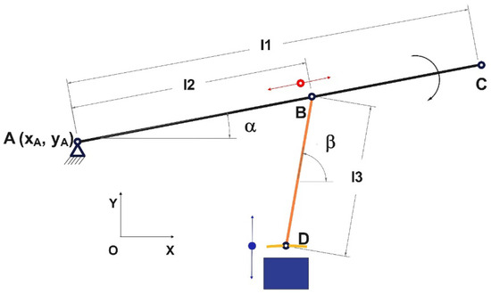
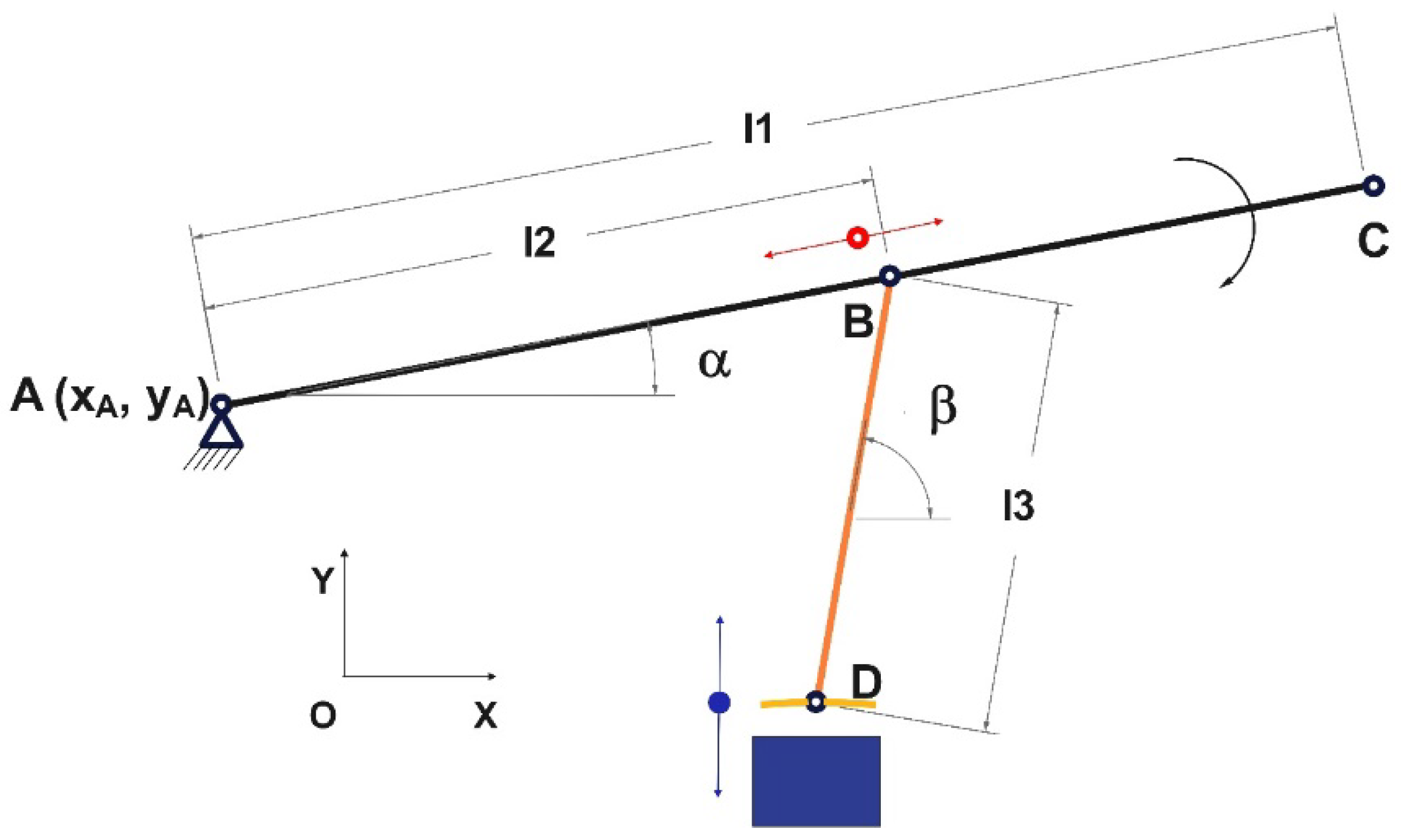
The objective of this paper is to develop a general kinematic model for a lever-link pressing mechanism employed in the technological process of compacting coagulate during cheese production. This work concentrates on deriving analytical formulas that define the position, velocity, and acceleration of the active pressing point D based on the mechanism’s geometric parameters and the angular displacement of the driving link, with all geometric points (A, B, D) and parameters (l1, l2) defined and illustrated in Figure 1. An important objective is to determine how shifting the intermediate joint B—through variations in the length of segment l2—impacts the mechanism’s kinematic response, with the purpose of identifying arrangements that yield favorable motion amplification and precise control of the active point. By establishing general equations and confirming their validity through numerical evaluation, the paper offers a solid theoretical foundation for improving the analysis and design of simple mechanical presses used in food-processing applications.
Figure 1.
A schematic representation of the mechanism under study.
In this context, the term adjustable geometric parameterization refers to the systematic variation of a geometric design parameter that defines the position of the intermediate coupling on the driving element (see Figure 1). This parameter is treated as an independent variable within the kinematic model and allows for the controlled modification of the mechanism’s configuration. Variations in this parameter lead to changes in the relative position of the mechanism elements, which in turn alter the geometry of the kinematic chain, including the length and orientation of the connecting link and the trajectory of the active point. The influence of this geometric parameter is incorporated explicitly into the analytical model through the formulation of position, velocity, and acceleration equations, enabling a direct evaluation of its effect on the kinematic response of the mechanism.
The novelty of this study lies in the development of a kinematic analytical framework capable of describing the motion of a planar pressing mechanism, featuring a lever and a joint, through a unified geometric formulation. Unlike numerous previous studies focused primarily on force transmission, structural evaluation, or application-oriented mechanism configurations, the current approach emphasizes the direct relationship between the mechanism’s geometry and the evolution of the main kinematic variables associated with the motion of the pressing equipment.
A central contribution of this work is the introduction of a variable geometric configuration generated by the controlled repositioning of the intermediate coupling point B along the actuator element AC. This approach makes it possible to evaluate how changes in the mechanism’s configuration affect the trajectory of the active element, the orientation of the connecting joint, and the variation in displacement, velocity, and acceleration throughout an operating cycle. The resulting analytical expressions remain valid for multiple admissible configurations of the mechanism without requiring reformulation of the model.
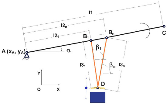
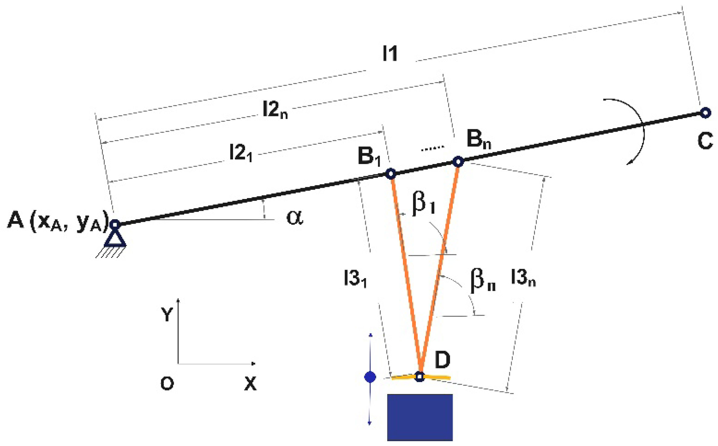
Another relevant aspect of the proposed methodology is the integration of geometric parameterization directly into the analytical kinematic formulation. The evolution of the mechanism’s shape, illustrated in Figure 2, is therefore treated not merely as a geometric representation, but as a determining factor that influences the characteristics of the motion.
Figure 2.
Variation of the position of the intermediate coupling B along the driving element AC, illustrating its role in modifying the geometric configuration of the planar lever-link mechanism presented in Figure 1.
2. Materials and Methods
This section presents the methodological framework used for the development and validation of the proposed kinematic model. It includes the description of the mechanical system, the assumptions adopted for the kinematic representation, the analytical approach used to derive the governing equations, and the numerical tools employed to evaluate and verify the model. The methodology is structured to allow the reproducibility of the results and the extension of the analysis to similar mechanisms.
2.1. The Mechanical System Examined
The theoretical study was conducted on a planar lever-link pressing mechanism used to compact the curd in the production of pressed cheeses. The analyzed mechanism consists of a rigid main element AC, of total length l1, hinged at the fixed point A; an intermediate point B located on element AC at a variable distance l2 from point A; and the element BD, connecting point B to the active point D. The coordinates of the fixed point A, denoted (xA, yA), are considered known and define the model’s reference frame (Figure 1), where the geometry of the mechanism and all associated notations are defined. All joints, including point B, are modeled as planar revolute joints.
Point D represents the active pressing element and is constrained to move exclusively in the vertical direction, which reflects the functional requirement of the analyzed manufacturing process. The mechanism’s motion is generated by the rotation of element AC around the fixed joint A, a rotation described by the variable angle α. In this work, the key geometric design parameter considered is the location of the intermediate point B, which is dictated by the value of l2.
In the adopted modeling approach, the length of the BD element, denoted l3, is not introduced as an independent parameter; rather, it is computed for each configuration based on the geometric constraint defined by the initial position of point D. As a result, any variation in l2 produces a geometric rearrangement of the mechanism, which in turn directly affects the trajectory and kinematic behavior of the active pressing point.
2.2. Analytical Approach and Methodology
2.2.1. Geometric Analysis of the Mechanism
The geometric study of the mechanism aimed to determine its kinematic arrangement based on the system’s dimensional parameters and the orientation of the driving link. The configuration was defined by the length of the primary link l1, its angular position α, and the adjustable parameter l2, which determines the position of the intermediate point B along segment AC. Point B acts as the intermediate coupling (revolute joint) between the driving element AC and the connecting link BD, and its location governs the overall geometry of the mechanism. By varying l2, the analysis examined how changes in this parameter influence the mechanism’s layout—particularly the length of link BD and the evolution of the kinematic angle β during the motion.
The Cartesian coordinate system was set with its origin at the fixed-point A, which allowed the analytical determination of the positions of points B, C, and D through trigonometric formulations and the mechanism’s geometric constraints (Figure 2). The coordinates of these fundamental points were computed using well-established procedures commonly applied in planar mechanism analysis [14,15,31]. At this stage, the purpose was to delineate the entire set of valid geometric configurations of the mechanism, forming the essential basis for the kinematic analysis that follows. The planar representation and the use of a Cartesian coordinate system are justified by the functional configuration of the mechanism, in which all relevant motions are constrained to a single plane.
Figure 2 illustrates the effect of the adjustable geometric parameter l2 on the configuration of the mechanism, highlighting the change in its geometric shape as the position of point B varies along the driving element.
2.2.2. Kinematic Position Analysis
The positional analysis was carried out by linking the mechanism’s configuration to a defined set of geometric parameters. The length of the main element l1 was treated as constant throughout the investigation, while the rotation angle α of the driving element was specified over a fixed interval, identical for all evaluated cases. Parameter l2, which determines the location of point B along segment AC, was varied within its admissible geometric limits to assess its influence on the overall configuration of the mechanism.
For each value of l2, the corresponding geometric length of the BD segment, the absolute position of point D, and the angle β of the BD segment relative to the horizontal axis were determined. Point D was treated as a moving point constrained to vertical displacement, such that its coordinate on the OX axis was kept constant, and the coordinate on the OY axis was calculated from the geometric conditions of the mechanism. This approach allows for the formulation of general position relations applicable to any admissible geometric configuration [14,15,31].
From a structural point of view, the mechanism was interpreted as a kinematic assembly consisting of the AC driving element and the kinematic group associated with the BD element and the adjacent B and D joints. This decomposition is consistent with classical methods of structural–kinematic analysis of planar mechanisms and facilitates the formulation of general calculation relationships [12,14,31]. In this paper, the analysis was aimed at obtaining a compact and unified mathematical model, independent of any design configuration.
2.2.3. The Analysis of Velocities
The determination of velocities represents a key step of the methodological approach, as it enables the evaluation of the kinematic response of the mechanism under the imposed motion law. The velocity analysis was carried out under the assumption that the mechanism’s kinematic variation is driven by the rotation of the AC input element, expressed through the time-dependent angle α(t). The driving angle α is defined over a prescribed variation interval, which is applied consistently in the numerical evaluation presented in the Section 4. In this framework, the angle β is not prescribed independently, but is determined by the instantaneous configuration of the mechanism and varies continuously within the admissible geometric domain. Consequently, all kinematic quantities of the active point D are expressed in terms of the angle α and its angular velocity.
In the literature, the analysis of velocities for mechanisms used to compress materials with rheological behavior can be performed for both variable-speed and constant-speed conditions [11,13,18,31,46,47,48,49,50,51]. In this study, a constant angular velocity was assumed, as this approach enables a clear illustration of how the geometric parameters influence the mechanism’s kinematic response and simplifies the development of general analytical expressions. Under this assumption, the variation of angle α is described by the following relationship:
where ω is the constant angular velocity, and t ∈ [0, T], with T representing the total duration of the motion defined for the analysis.
Based on this assumption, the velocity of point D was determined by taking the time derivative of the position equations. Since point D is constrained to move exclusively in the vertical direction, the horizontal component of the velocity is zero, and the analysis focused on the vertical component of the absolute velocity. The resulting equations are expressed in terms of the mechanism’s geometry, the instantaneous position of the driving element, and the constraints imposed on the motion of the active point [12,14,31].
2.2.4. Analysis of Accelerations
The calculation of accelerations complements the kinematic analysis and provides additional information regarding the variation of motion, being an integral part of the proposed methodological framework.
The linear acceleration of the active pressing point D was determined by further differentiating the velocity equations obtained in the previous step. In accordance with classical methods of analyzing planar mechanisms, this approach allows for the evaluation of the variation in the absolute acceleration of moving points and is suitable for articulated mechanisms used in pressing applications [13,31,42].
Given the kinematic constraint imposed on point D, according to which it moves exclusively in the vertical direction, the component of acceleration along the horizontal axis was zero. Consequently, the investigation was directed toward the vertical component of the absolute acceleration. The assumption of a constant angular velocity for the AC driving element was preserved at this stage as well, which made it possible to derive analytical expressions that depend solely on the geometric parameters of the mechanism and on the variation of angle α.
In this manner, the acceleration analysis completes the kinematic characterization of the mechanism and offers valuable insights into the system’s behavior under idealized conditions, assuming no friction and perfectly rigid components [13,31]. Although the accelerations obtained do not fully describe the actual behavior of the mechanism under load, they constitute a necessary basis for further dynamic developments and for evaluating the stability of the operating regime.
2.3. Numerical Verification and Processing of Results
The numerical implementation and validation of the analytical model constitute an essential stage of the methodology, ensuring the correctness and applicability of the derived kinematic relationships.
The mathematical analysis and numerical implementation of the kinematic model were performed using Mathcad Prime 11.0.1.0, while graphical validation and simulation were carried out using GIM 2025.4 software.
Several software tools with complementary roles were used to verify the analytical relationships developed within the kinematic model. The numerical implementation of the calculation relationships for position, velocity, and acceleration was performed in Mathcad Prime 11 [65], which allowed for the discrete evaluation of kinematic quantities for a predefined set of geometric configurations and driving angle values.
The geometric modeling and kinematic simulation of the mechanism were performed using GIM (Geometric Interactive Modeler) software [66,67], which was used for the visual and numerical verification of the trajectories and kinematic parameters associated with the active point D. The final graphical representations of the results were created in OriginPro 2019b [68] to highlight the influence of geometric parameters and temporal variation on the kinematic behavior of the mechanism.
The agreement between the analytical results and those obtained through kinematic simulation was evaluated by comparing the corresponding velocity values for the configurations under investigation.
3. Generalized Kinematic Modeling
This section presents the development of the generalized kinematic model of the analyzed mechanism. The modeling is based on the geometric configuration of the system, the imposed kinematic constraints, and the analytical formulation of the position, velocity, and acceleration relationships.
3.1. General Theory Overview
The primary goal is to establish general equations—independent of the mechanism’s specific configurations—that enable the determination of the positions, angles, and kinematic quantities associated with the active pressing point D for any admissible set of geometric parameters. To achieve this, the theoretical model is developed using a series of standard assumptions designed to ensure a purely kinematic representation of the system.
3.2. Hypotheses of the Cinematic Model
To derive the analytical expressions, the mechanism was represented using standard assumptions typically employed in the kinematic study of planar systems. These assumptions allow the formulation of a general model that is not influenced by elastic deformations, manufacturing tolerances, or interactions between the mechanism and the material being processed. The assumptions adopted in the analysis are:
- -
- All mechanism components are considered perfectly rigid, ensuring that the lengths of segments l1, l2, and l3 remain constant for every configuration examined.
- -
- The kinematic joints are treated as ideal, meaning they exhibit no radial or axial clearance and impose no additional constraints on the relative motion of the connected elements. Under these idealized conditions, the angles α and β are defined strictly by geometric relations.
- -
- Friction in joints and guiding elements is neglected, so the model describes purely kinematic behavior, with velocities and accelerations obtained directly from the position equations.
- -
- The active point D is restricted to vertical motion only, which corresponds to enforcing a constant horizontal coordinate xD = d, consistent with the presence of an ideal prismatic guide.
In addition to the general modeling assumptions, the following geometric constraints were considered:
- -
- the mechanism is constrained to planar motion; the driving element rotates about a fixed axis at point A;
- -
- the intermediate point B is restricted to move along the length of the driving element AC according to the parameter l2;
- -
- the connecting link BD preserves a constant length for each configuration;
- -
- the active point D is constrained to move exclusively along a vertical direction, corresponding to a prismatic guide.
These constraints define the admissible configurations of the mechanism and are explicitly reflected in the analytical formulation.
By adopting these assumptions, the resulting model describes solely the kinematic behavior of the mechanism, without accounting for the effects of deformability, friction, or manufacturing tolerances. Consequently, the equations derived below should be interpreted as valid within an idealized kinematic regime, suitable for the preliminary stages of analysis and design.
3.3. Definition of the Reference System and Geometric Parameters
The Cartesian reference frame has been defined with its origin at the fixed-point A, with the OX and OY axes conventionally oriented in the plane of the mechanism. The link AC, of total length l1, rotates about the fixed joint A, forming a variable angle α with the horizontal axis. The intermediate point B is located on the link AC at a distance l2 from point A, such that its coordinates are expressed by the following equations:
Its position on the vertical axis results from the geometric condition for the mechanism to be closed. The element BD, of length l3, connects point B to point D. For each configuration defined by the parameter l2, the value of l3 is determined once based on the initial position imposed for point D, and is then treated as a constant geometric parameter within that configuration. This clarification is crucial for accurately interpreting the position, velocity, and acceleration relationships presented in the following sections.
3.4. Evaluation of the BD Segment Length
To develop the generalized kinematic model, it was assumed that the mechanism begins from a reference position in which point D has identical coordinates for all analyzed configurations of point B. Under this assumption, for each value of parameter l2, the length of segment BD is obtained from the geometric distance between points B and D:
By substituting the coordinates of point B and the condition xD = d, we obtain the general expression used in the calculation of l3:
This approach allows the position of the intermediate point B to be treated as a geometric design variable and is suitable for studying the influence of design parameters on the mechanism’s configuration. From a methodological standpoint, the procedure is compatible with the classical vector analysis of planar mechanisms, in which the lengths of the elements and the positions of the joints are related through geometric closure conditions [14,15,31].
3.5. Position Relations for the Active Point D
Since the mechanism under analysis is designed for the cheese-pressing process, the movement of the active point D was required to be exclusively vertical, with the horizontal component nullified. This constraint stems from the technological operating conditions: the product is pressed in a mold with a predetermined geometry (cylindrical or prismatic), which does not allow for lateral movement of the pressing element. Consequently, point D is associated with the moving element that closes the container (functionally similar to a piston) and transmits the load in the direction of the vertical axis. For this reason, the coordinates of the point (i.e., of coupling D) on the OX axis are written as:
We have two solutions, but in Figure 1 and Figure 2, point D is below point B, so its y-coordinate must be smaller; therefore, we choose the minus sign:
from which it follows
We denote by:
Then Equation (7) becomes:
3.6. Determination of the Kinematic Angle β
The BD element forms an angle β with the horizontal, which varies both during the pressing process and due to the different positioning of coupling B on the AC element. Starting from the calculation equation corresponding to the vector that defines the BD element:
and from the condition regarding the length of the rigid bar BD:
it follows that:
Since, based on the configuration of the mechanism, point D is located below point B, the negative solution is chosen:
The angle β is the angle formed by the vector and the OX axis. By definition:
In the actual configuration of the mechanism, the BD vector points to the left and downward, so:
- -
- the vertical component is negative;
- -
- the horizontal component can be positive or negative, but the physical direction requires β > 90°.
To preserve the correct geometric meaning, the angle is expressed as:
Substituting Equation (8) into Equation (15) yields the final form:
3.7. Speed Ratios of the Active Point
The motion of the mechanism is generated by the rotation of the AC drive element, described by the angle α = α(t). Consequently, all kinematic quantities of point D become composite functions of time due to their dependence on α. Since point D is constrained to move exclusively in the vertical direction, the velocity component along the OX axis is zero, and the absolute velocity of the active point reduces to its vertical component.
Since the displacement of the point of interest relative to the OX axis is 0, the vertical velocity (corresponding to the motion along the OY axis) is obtained by differentiating the yD coordinate with respect to time:
Since yD = yD(α) and α = α(t), the chain rule applies, and we obtain
but:
Then Equation (18) becomes:
Equation (18) is derived:
Substituting Equations (19) and (21) into (18) yields:
or
The full vector form of the velocity of point D:
3.8. Acceleration Relationships of the Active Point
The absolute acceleration of point D was determined by further differentiating the vertical velocity equation with respect to time. As in the case of the velocity analysis, the constraint of vertical guidance imposed on the active point leads to the cancellation of the horizontal component of acceleration. Consequently, the linear acceleration of point D is characterized exclusively by its vertical component.
To determine the acceleration at point D, we start from the condition described in the section on linear velocity, respectively:
Since point D is guided exclusively along the vertical axis:
- -
- its position along the OX axis is constant,
- -
- its velocity along the OX axis is zero,
- -
- its acceleration along the OX axis is zero, ;
and relative to the OY axis:
Substituting the terms from the calculation relation (21) into relation (26), we obtain:
but:
Then Equation (27) becomes:
and finally, Equation (26) can be written as:
The expanded form of the calculation is:
3.9. The Relevance of the Developed Model
The analytical relationships developed in this chapter provide a general framework for the kinematic description of the analyzed pressing mechanism and allow for a systematic evaluation of the influence of geometric parameters on the motion of the active point D. The developed model explicitly accounts for the constraint imposed on the vertical motion of the active point, the geometric definition of the intermediate joint B, and the way in which the primary kinematic quantities vary with the adjustment parameter l2. In this form, the resulting relationships are directly applicable in numerical implementations, sensitivity studies, and subsequent stages of geometric optimization of the mechanism.
From an engineering perspective, the model provides a basis for further analytical developments focused on analyzing transmitted forces, identifying configurations that are favorable in terms of motion amplification, or integrating more complex dynamic and rheological models. Consequently, the theoretical contribution of this chapter is not only to obtain the calculation relationships but also to provide an extensible mathematical framework for the study of simple pressing mechanisms used in food processing and other similar technical applications.
4. Results
4.1. Parameters Used in the Numerical Study
To numerically evaluate the analytical relationships developed in the previous chapter, a set of geometric and kinematic parameters representative of the analyzed mechanism was defined. These values were determined by considering both the particular design layout of a basic lever-type press and the reference benchmarks provided in the specialized literature and in the technical documentation that defines the working dimensions [39,40,41,42,43,44,45,46,47,48,49,50,51,52,53,54,55,56,57,58,59,60,61,62,63,64,65,66,67,68,69,70,71,72,73,74,75,76].
In the study, the length of the main AC element was set to 86 cm, and the position of the intermediate point B on this element was varied so that the parameter l2 took values in the range of 25–65 cm. The driving element was moved by rotating it clockwise around the fixed-point A. To ensure consistency between the kinematic model and the reported velocity values, the variation in angle α should be interpreted as a displacement from 10° to −10°, corresponding to an effective variation of 20° in a clockwise direction. This interval defines the imposed range of the driving angle used in the present study.
The total duration of this motion was 18 min, which corresponds to a constant angular velocity of ω = 3.232 × 10⁻⁴ rad/s, or a rotational speed of 0.00309 rpm. In the numerical calculation, the variation of time and angle α was discretized into 200 values, and the variation of the parameter l2 into 100 values. The implementation of the analytical relations was performed in Mathcad Prime 11 [59], and the graphical representations were generated in OriginPro 2019b [68].
4.2. The Effect of Parameter l2 on the Length of the BD Element
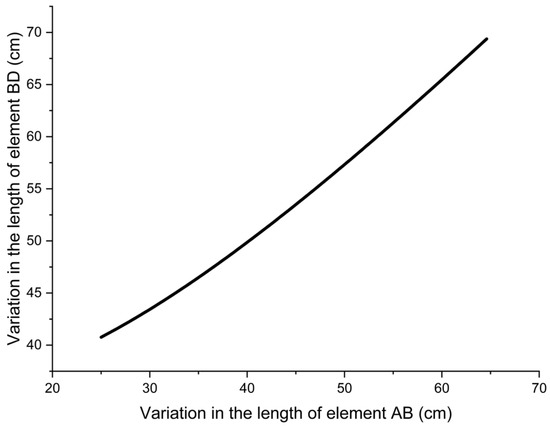
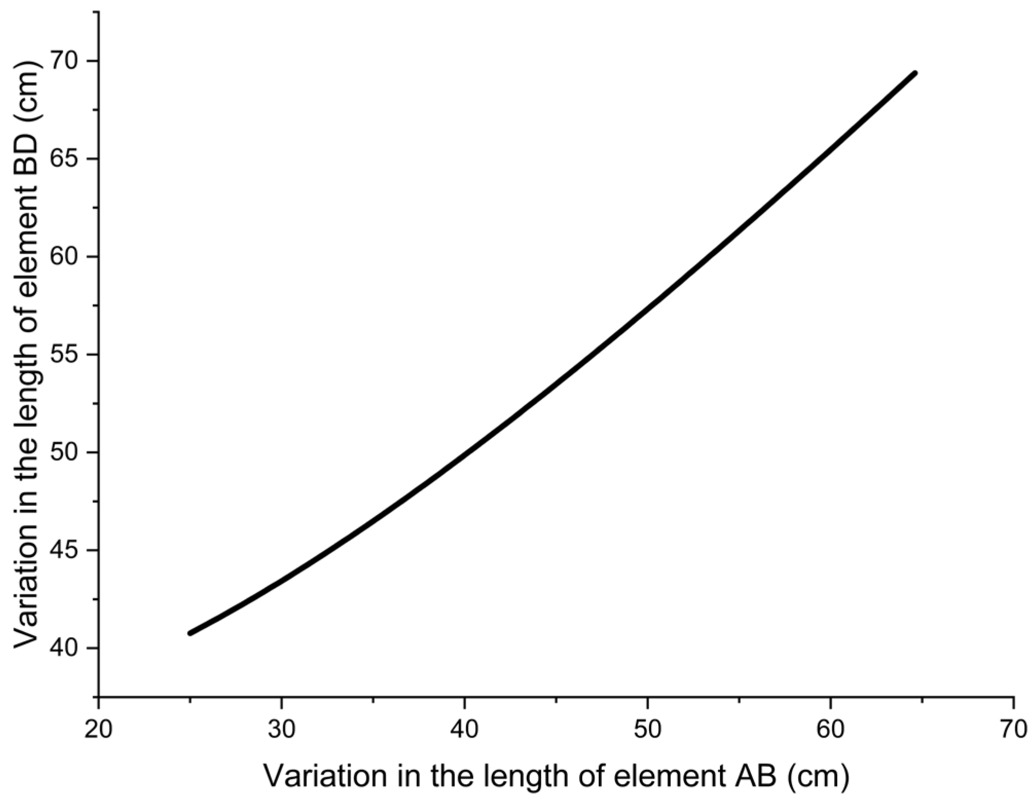
Figure 3 shows how the length of the BD element varies with the position of the intermediate point B, represented by parameter l2. The relationship between these two quantities is observed to be monotonically increasing and nonlinear, indicating that the movement of point B along the AC element produces a substantial geometric reconfiguration of the kinematic assembly.
Figure 3.
The change in the length of segment BD as a result of varying the distance between points A and B.
For small values of l2, the increase in the length of BD is moderate, suggesting a relatively low geometric sensitivity of the mechanism in this region. As point B approaches the end of element AC, the slope of the curve increases, highlighting a more pronounced amplification of the geometric effect of l2 on the length of element BD. This trend confirms that the position of intermediate point B can be treated as a relevant adjustment parameter in the configuration of the mechanism.
The convex shape of the curve indicates that the ratio between the variation of l2 and the variation of l3 is not linear, but is governed by the trigonometric relationships associated with the analyzed planar mechanism. Consequently, the selected position of point B affects not only the geometric length of the BD element but also the overall kinematic sensitivity of the system.
4.3. The Progression of the β Angle
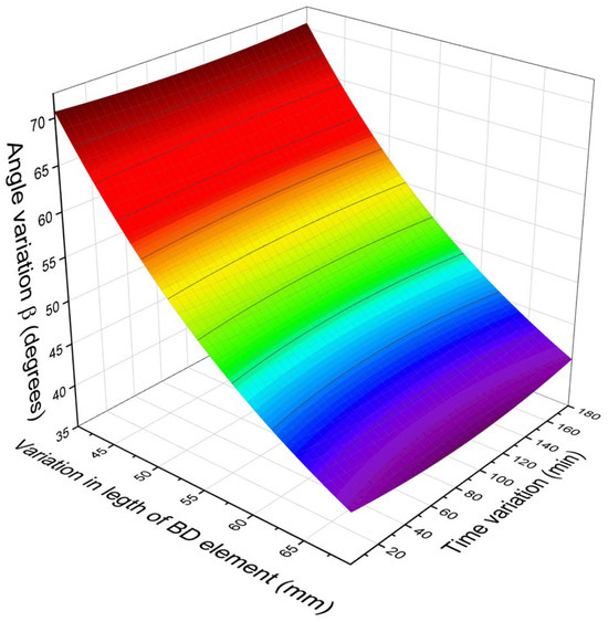
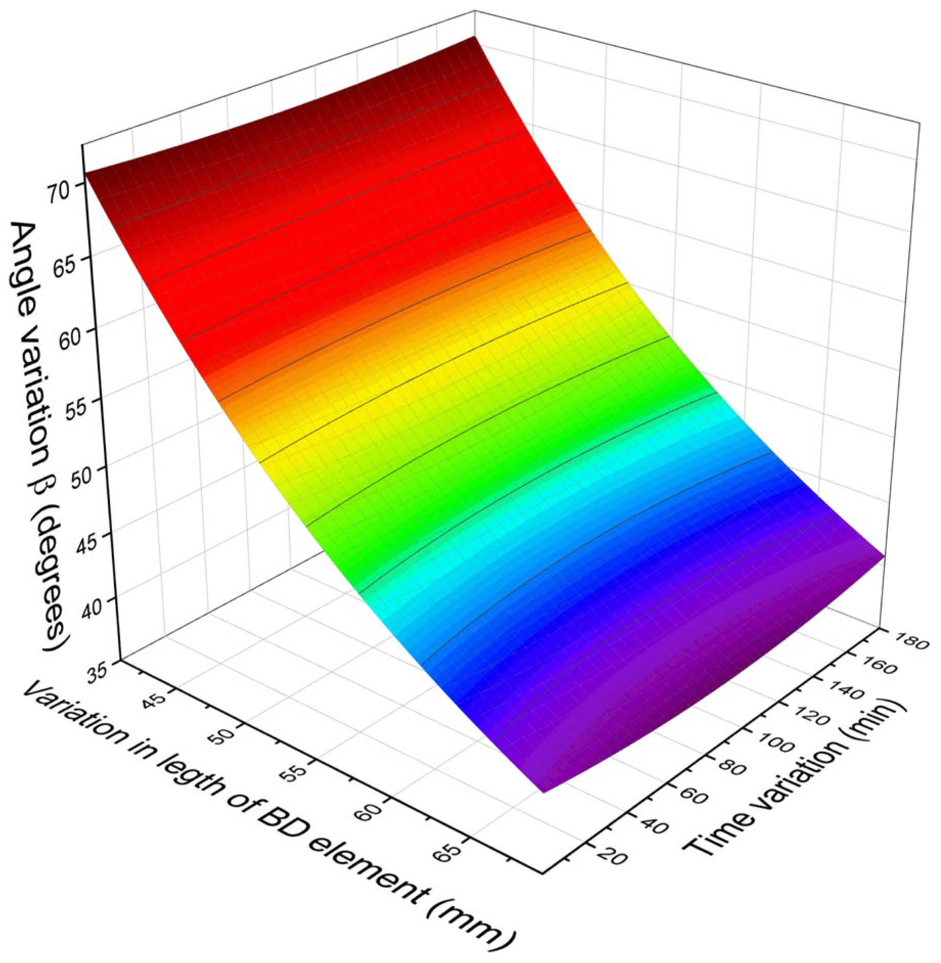
Figure 4 presents the variation of angle β with respect to both the length of element BD and time. The three-dimensional visualization clearly shows that β is governed simultaneously by the geometric parameterization of the mechanism and by the instantaneous configuration of the driving link. The resulting surface is smooth and continuous, indicating that the kinematic response exhibits no discontinuities within the investigated domain.
Figure 4.
Variation of the angle β as a function of the length of the BD element and time.
In the time direction, the angle β exhibits a progressive variation, determined by the rotation of the AC element. In the direction associated with the length of the BD element, a nonlinear dependence is observed, indicating that the mechanism becomes more sensitive to changes in the geometric parameter as the configuration deviates from its initial values. In kinematic terms, this means that the same increment of geometric variation does not produce the same effect on the orientation of the BD element across the entire analyzed domain.
To avoid ambiguities in interpretation, it is recommended that the description of this figure in the final version of the manuscript focus strictly on the geometric orientation of the BD element and on the sensitivity of angle β to variations in the independent parameters, without introducing dynamic or technological interpretations that are not directly supported by the kinematic model.
4.4. The Progression of the Active Point D’s Position
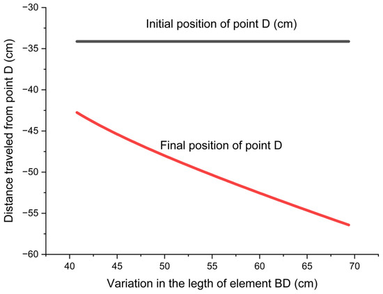
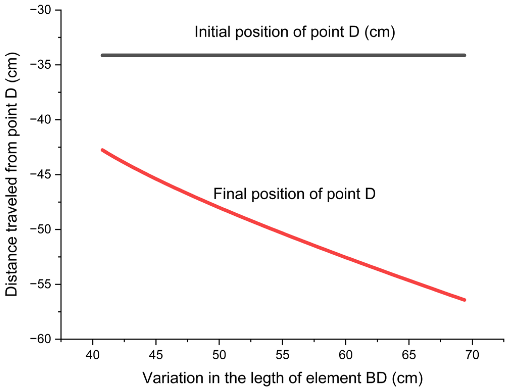
Figure 5 shows how the position of the active point D varies with the length of the BD element, for both the initial configuration and the final configuration corresponding to the analyzed motion. The fact that the initial position of point D is identical for all BD values confirms that the model was formulated using a unified initial condition for every configuration of the mechanism.
Figure 5.
The variation in the position of point D as a function of the variation in the length of segment BD.
By comparison, the final position of point D shows a clear nonlinear dependence on the length of segment BD. For smaller values of this length, the descent of the active point is reduced, while for larger values of BD, a marked increase in vertical displacement is observed. This behavior indicates that the mechanism becomes more sensitive to changes in geometric parameters during the final stages of the motion.
The displacement between the initial and final positions of point D defines the mechanism’s effective stroke. The findings demonstrate that this stroke can be markedly influenced by adjusting the location of point B along the AC element, highlighting the function of l2 as a geometric control parameter in both the design and functional tuning of the mechanism.
4.5. The Evolution of the Speed of the Active Point D
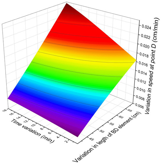
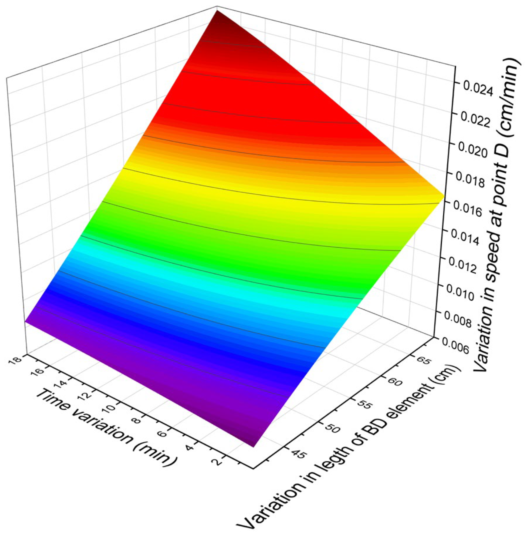
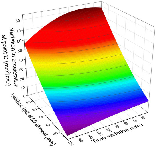
Figure 6 shows how the vertical velocity of the active point D varies with time and with the length of the BD element. The data indicate that the velocity is jointly affected by the position of the driving element and by the mechanism’s geometric configuration. In general, within the analyzed range, the velocity increases gradually both as the mechanism approaches the end of its stroke and as the BD element becomes longer.
Figure 6.
The variation of the linear velocity corresponding to point D as a function of time and the variation in the length of segment BD.
This trend indicates that the mechanism exhibits a more pronounced kinematic amplification in configurations associated with large values of the geometric parameter l2, or of the corresponding length BD. In other words, the same slow rotation of the driving element can produce a greater variation in the velocity of the active point in certain geometric regions of the mechanism.
The interpretation of this figure must be limited strictly to kinematic aspects, as the developed model is purely kinematic and does not include an analysis of transmitted forces or mechanism–material interaction. Consequently, conclusions must be formulated strictly in terms of displacement and velocity, without directly extrapolating to mechanical or technological quantities not calculated within the scope of the study.
4.6. The Evolution of the Acceleration of the Active Point D
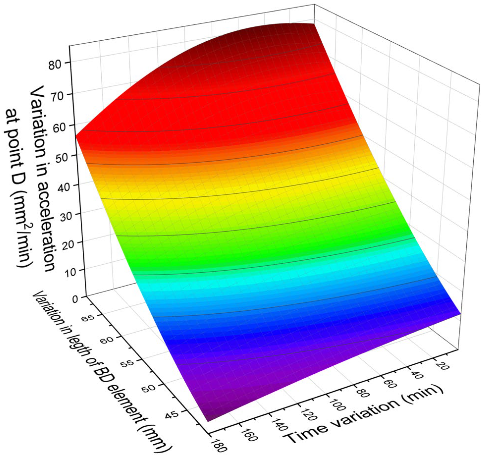
Figure 7 shows the variation of the vertical acceleration of the active point D as a function of time and the length of the BD element. Throughout the entire analyzed domain, the acceleration values remain low, indicating a slow change in velocity under the considered kinematic regime. The evolution of acceleration is relatively uniform and does not show any jumps or sudden variations, a finding consistent with the hypothesis of slow actuation and a constant angular velocity of the driving element.
Figure 7.
The variation of the linear acceleration corresponding to point D as a function of time and the variation in the length of segment BD.
The predominantly negative sign of the vertical acceleration reflects the geometric shape of the position function yD(α), namely a downward concavity in the analyzed domain. In interpreting these results, it must be emphasized that the accelerations obtained describe exclusively the idealized kinematic behavior of the mechanism and cannot be used, in the current form of the model, to draw direct conclusions regarding the actual dynamic stresses of the structural assembly or the pressed product.
Therefore, this figure should be interpreted as confirmation of the slow and controlled nature of the active point’s motion within the analyzed kinematic regime, rather than as a direct demonstration of the system’s complete dynamic behavior.
4.7. Verification of Analytical Results Through Kinematic Simulation
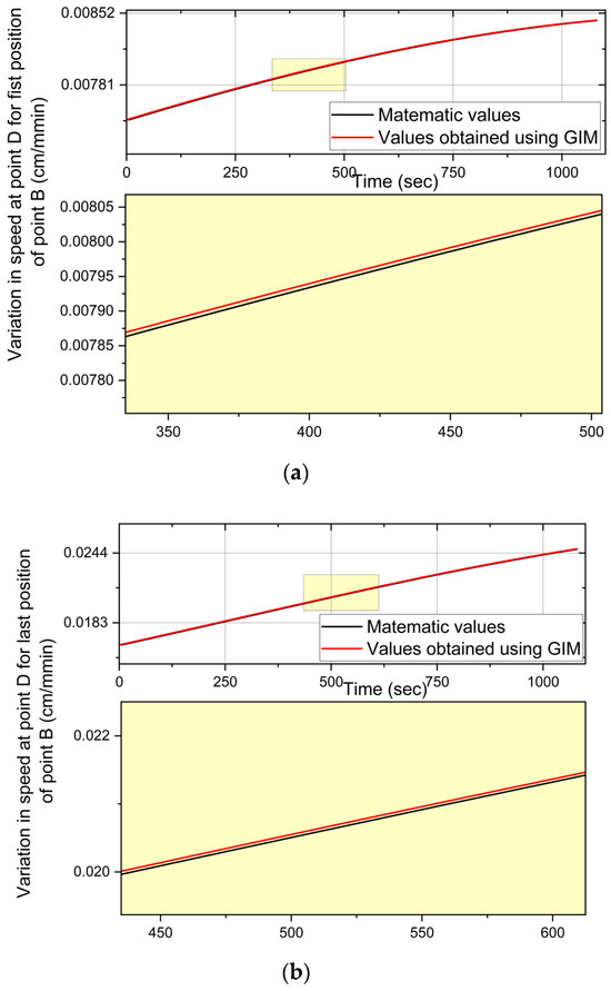
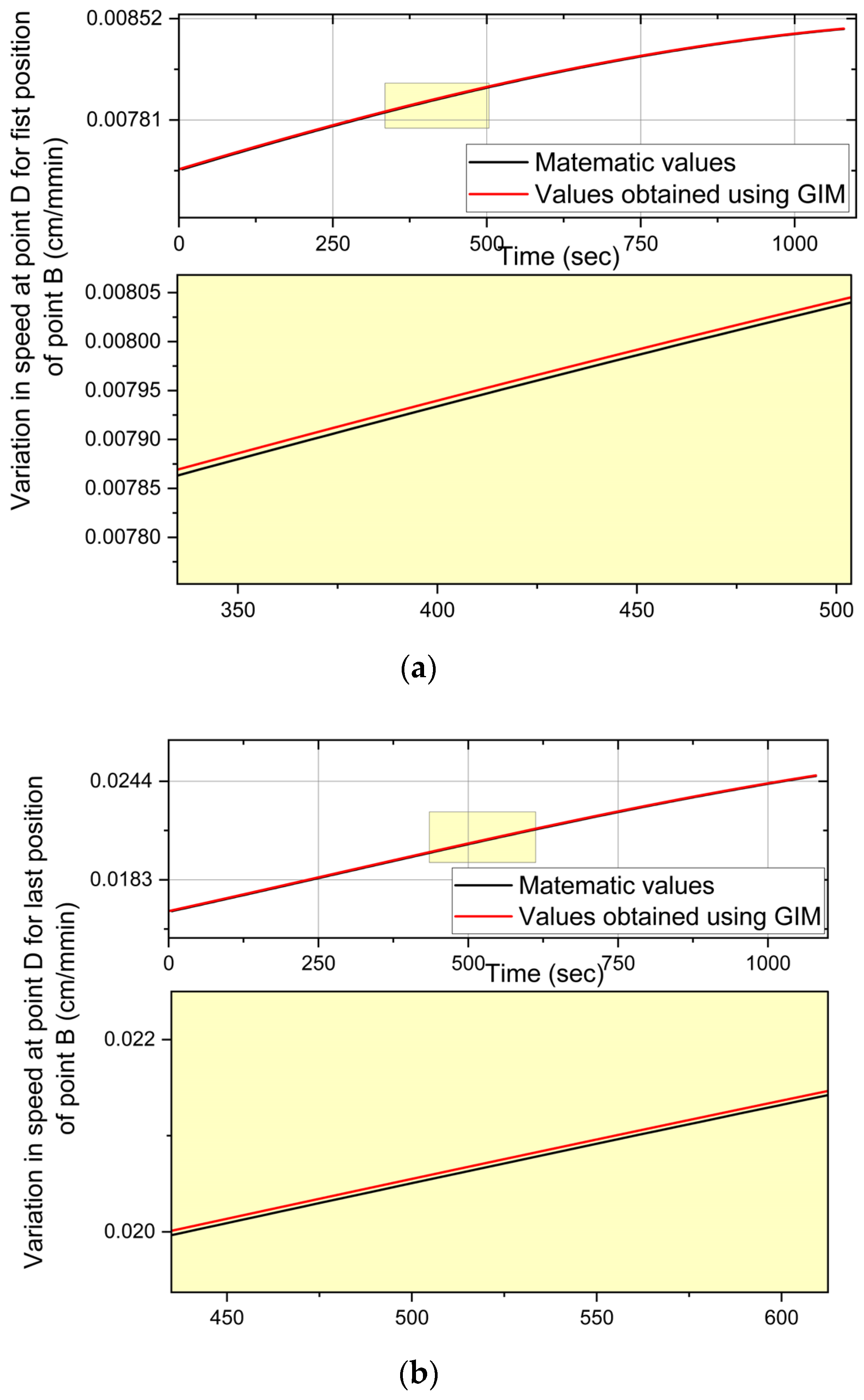
To verify the numerical implementation of the analytical model, the results obtained in Mathcad Prime were compared with those from the kinematic simulation performed in GIM 2026.1 [60,61]. During the simulation, 10,800 values were generated, which were used for comparison with the set of values obtained based on the analytical relationships implemented in Mathcad [59]. This comparison serves to verify the internal consistency of the model and the correctness of its implementation in different software environments.
Figure 8 presents a comparative analysis of the variation in the velocity of the active point D for two extreme configurations of point B: one corresponding to a position close to the fixed joint A and one corresponding to a position close to the end of the AC element. In both cases, the analytically and numerically obtained curves overlap very well, indicating a high degree of agreement between the two evaluation methods.
The observed differences are minor and can be attributed to numerical discretization and the tolerances of the kinematic solver.
In both cases, the excellent agreement between the analytical results and those obtained through GIM simulation confirms:
- -
- the accuracy of the formulated calculation relationships;
- -
- the correct implementation of the mechanism in the simulation environment;
- -
- the possibility of using GIM simulation as a kinematic validation tool for low-speed operating conditions.
All figures presented in this section are discussed in relation to both the geometric configuration of the mechanism and the corresponding kinematic variables, ensuring a consistent interpretation of the results obtained.
5. Discussion of the Kinematic Significance and Engineering Implications of the Results
The results clearly highlight the role of geometric parameterization in determining the kinematic response of the analyzed pressing mechanism. In particular, the position of the intermediate coupling B, defined by the parameter l2, significantly influences both the length of the BD element and the evolution of the position, velocity, and acceleration of the active point D. This observation confirms that parameter l2 can be treated as a geometric design variable, capable of modifying the kinematic sensitivity of the mechanism without altering its basic architecture.
From this perspective, the results are consistent with the literature on planar articulated mechanisms, in which the position of the intermediate joints plays a decisive role in determining the motion regime of the active points and in defining functionally favorable configurations [12,14,31]. In the present case, the model extends this idea to a simplified configuration of a pressing mechanism, relevant for food processing applications and for low-complexity manual or semi-mechanized mechanisms.
It should be emphasized that the model developed in this paper is purely kinematic in nature and was formulated under the assumption of perfectly rigid elements, ideal couplings, and a frictionless vertical guide. Consequently, the results describe only the geometric and kinematic response of the mechanism and do not include the effects associated with technological load, rheological behavior of the processed material, structural deformability, or force transmission.
A key finding is the nonlinear nature of the relationship between the position of point B, expressed as l2, and the geometric length of segment BD. An increase in l2 leads to an accelerated increase in l3, indicating that the mechanism does not respond uniformly to changes in the geometric parameter. In terms of design, this relationship highlights the existence of regions where a relatively small change in the position of point B can produce a more pronounced change in the overall configuration of the mechanism.
This nonlinear dependence highlights that the placement of point B should be understood not merely as a geometric sizing choice, but as a parameter that actively shapes the kinematic behavior of the mechanism. Consequently, it functions not only as a means of positioning the intermediate link but also as a factor that indirectly shapes the effective stroke and the mechanism’s sensitivity to the motion imposed by the driving element.
The analysis of angle β reveals that the mechanism progresses through several distinct kinematic stages, in which the orientation of element BD is dictated jointly by the instantaneous configuration of the driving link and the overall geometric arrangement. At the beginning of the motion, variations in α induce only slight changes in β, whereas toward the end of the stroke, the angular response becomes markedly more sensitive. This trend reflects an increase in geometric sensitivity as the mechanism approaches the final configuration under study. Consequently, the geometric configuration of the mechanism influences not only the required final position of the moving point, but also how the orientation of the intermediate elements evolves throughout the stroke.
The results regarding the vertical position of point D show that the amplitude of the effective displacement increases with the geometric configuration of the mechanism. For smaller values, the vertical displacement of the active point is limited, whereas for larger values, the mechanism develops a greater effective stroke. This trend indicates that repositioning point B directly influences the magnitude of the active point displacement.
The fact that the initial position of point D was set identically for all analyzed configurations ensures the consistency of the comparison between the investigated geometric variants and allows for the exclusive highlighting of the effect of parameter l2.
Regarding the velocity of the active point D, the results show that it increases progressively throughout the motion and reaches its highest values near the final configuration analyzed. This trend is consistent with the nonlinear nature of the kinematic relationships and with the increasingly pronounced influence of geometric parameters in the final phases of the stroke. Furthermore, the configurations corresponding to high values of l2 generate higher vertical velocities, which confirms the kinematic amplification associated with the repositioning of intermediate point B.
When interpreting these results, it is important to note that the developed model describes only the kinematic motion of the active point and, in its current form, does not allow for a direct assessment of the pressure or force transmitted to the product. Therefore, the increase in speed must be interpreted strictly as an indication of the intensification of the active point’s movement, and not as a direct measure of the level of mechanical stress applied to the material being pressed.
The low values of vertical acceleration indicate that, under the kinematic conditions analyzed, the mechanism exhibits a relatively smooth variation in the velocity of the active point. The absence of sudden variations in acceleration suggests stable kinematic behavior within the model’s assumptions and is consistent with the choice of a constant angular velocity and the slow nature of the motion imposed on the leading element.
However, these results should be interpreted with caution. The accelerations calculated in this paper describe the idealized kinematic response of the mechanism and do not account for the effects of the technological load, friction, the deformability of the components, or interaction with the pressed material. Consequently, they provide useful information about the regularity of the motion, but cannot be considered sufficient for a complete evaluation of the dynamic behavior of the real system.
Regarding the actual pressing process in the food industry, it should be emphasized that the results presented in this paper describe an idealized kinematic regime, determined exclusively by the geometry of the mechanism and the law governing the variation of the drive angle α. In practice, the actual displacement of the active point and the mechanism’s response can be influenced by the mechanical behavior of the material being compacted, contact friction, uneven mass distribution, and changes in the product’s rheological properties [52,53,54,55,56,57].
The literature indicates that food materials such as coagulants, protein pastes, or semi-solid masses often exhibit viscoelastic and time-dependent behavior, which can alter the actual displacement regime and the response to compression [52,53,54,55,56,57]. In this context, the kinematic relationships obtained in this study should be viewed as a necessary theoretical foundation for further development, in which the geometric model is coupled with a mechanical or rheological model appropriate for the processed material.
An important aspect of the study is the comparison between the results obtained analytically and those derived from the kinematic simulation performed in the GIM software. The excellent overlap of the curves representing the velocity of the active point D indicates a high degree of agreement between the derived equations and the numerical implementation of the mechanism in the simulation environment [66,67].
This agreement should be interpreted as a verification of the consistency of the analytical model and its numerical implementation, not as an experimental validation of the behavior of the actual mechanism. The small differences observed locally are consistent with the time discretization and the tolerances of the kinematic solver and do not affect the overall conclusion regarding the consistency of the developed model.
Overall, the analysis of the results shows that the mechanism’s geometry can be used as a tool for fine-tuning the system’s kinematic behavior. Parameter l2, associated with the position of the intermediate coupling B, systematically influences the effective stroke, the orientation of the intermediate element, and the speeds developed by the active point, which gives the mechanism a functional flexibility that is relevant from a design perspective.
This feature makes the analyzed mechanism suitable for applications requiring simple geometric adaptation of the system without altering its basic design principle. From the perspective of applied mechanical engineering, the developed model can serve as a basis for subsequent stages of geometric optimization, force analysis, evaluation of mechanical advantage, and integration of more advanced drive and control systems.
The present analysis is limited to a purely kinematic approach, and several directions can be considered for further development. An important extension would be the inclusion of dynamic effects, allowing the evaluation of transmitted forces, mechanical advantage, and stresses in the structural elements. Another relevant direction is the integration of an appropriate rheological model, in order to correlate the kinematic response of the mechanism with the actual behavior of the processed material during compaction [52,53,54,55,56,57]. In addition, the comparison between analytical predictions and experimental measurements on a real prototype would provide a basis for further validation of the model.
6. Conclusions
The purpose of this work was to construct a general kinematic model for a lever-link pressing mechanism used in compaction operations. The analytical expressions derived enable the characterization of the position, velocity, and acceleration of the active pressing point D based on the mechanism’s geometric configuration and the motion law of the driving element. In this formulation, the model allows the evaluation of how geometric parameters affect the mechanism’s kinematic behavior.
The change in the geometric configuration of the mechanism, generated by the adjustment of parameter l2, represents the basis for the observed variations in kinematic behavior.
The results show that the position of the intermediate point B, defined by the parameter l2, significantly influences the kinematic configuration of the mechanism. Variations in l2 lead to nonlinear changes in the length of element BD and to corresponding variations in the position, velocity, and acceleration of the active point D.
Analysis of the numerical results shows that the mechanism becomes more sensitive to variations in the actuation angle in configurations associated with high values of parameter l2. Under these conditions, the active pressing point exhibits greater vertical displacement and higher speeds in the final stages of the stroke, indicating a marked increase in kinematic amplification.
The low acceleration values calculated for active point D indicate a relatively uniform kinematic behavior in the analyzed operating regime. Within the adopted assumptions, this result suggests stable behavior of the mechanism in terms of the variation in the active point’s velocity. However, these conclusions must be interpreted strictly within the limits of the idealized kinematic model, in the absence of an analysis of forces, friction, and interaction with the material being pressed.
A comparison of the analytical results with those obtained through kinematic simulation in GIM showed very good agreement, indicating a high level of consistency between the developed computational relationships and their numerical implementation. This comparison serves as a verification of the analytical model with respect to a kinematic simulation environment.
The developed model may serve as a useful basis for further studies involving dynamic analysis, force transmission, rheological interaction with processed materials, and experimental validation of the mechanism.
Author Contributions
Conceptualization, E.M., O.B. and A.-D.C.; methodology, E.M.; software, E.M.; validation, E.M., O.B. and A.-D.C.; formal analysis, M.P.-L. and D.M.; investigation, M.J. and M.A.P.; data curation, E.M.; writing—original draft preparation, A.-D.C.; writing—review and editing, E.M., O.B. and A.-D.C.; visualization, I.C.P.; supervision, E.M. All authors have read and agreed to the published version of the manuscript.
Funding
This research received no external.
Institutional Review Board Statement
Not applicable.
Informed Consent Statement
Not applicable.
Data Availability Statement
The original contributions presented in this study are included in the article. Further inquiries can be directed to the corresponding author.
Conflicts of Interest
The authors declare no conflicts of interest.
References
- Fox, P.F.; Guinee, T.P.; Cogan, T.M.; McSweeney, P.L.H. Fundamentals of Cheese Science; Springer: Berlin/Heidelberg, Germany; New York, NY, USA, 2017. [Google Scholar]
- Walstra, P.; Wouters, J.T.M.; Geurts, T.J. Dairy Science and Technology; CRC Press: Boca Raton, FL, USA, 2006. [Google Scholar]
- Tamime, A. Cheese: Chemistry, Physics and Microbiology; Academic Press: Cambridge, MA, USA, 2017. [Google Scholar]
- Feeney, E.; Fox, P.; Guinee, T. Effect of ripening temperature on the quality of low moisture Mozzarella cheese: 1. Composition and proteolysis. Lait 2001, 81, 463–474. [Google Scholar] [CrossRef] [Scilit]
- Van Slyke, L.L. Modern Methods of Testing Milk and Milk Products: A Handbook; Legare Street Press: Charleston, SC, USA, 2023. [Google Scholar]
- McSweeney, P.L.H. Cheese: Biochemistry of cheese ripening. Encycl. Dairy Sci. 2011, 57, 127–144. [Google Scholar]
- Jonkers, N.; van Dommelen, J.A.W.; Geers, M.G.D. Experimental characterization and modeling of the mechanical behavior of brittle 3D printed food. J. Food Eng. 2020, 278, 109941. [Google Scholar] [CrossRef] [Scilit]
- Cabal-Prieto, A.; Sánchez-Arellano, L.; Herrera-Corredor, J.A.; Oney-Montalvo, J.E.; Can-Herrera, L.A.; Castillo-Zamudio, R.I.; Hernández-Arzaba, J.C.; Rodríguez-Miranda, J.; Prinyawiwatkul, W.; Valdivia-Sánchez, J.; et al. Impact of pressing time on the microstructure of two types of goat cheeses and its relationship with sensory attributes. J. Texture Stud. 2024, 55, e12865. [Google Scholar] [CrossRef] [Scilit] [PubMed]
- Rafiq, S.M. Technological Advances and Trends in Cheese Making; Springer Nature: Berlin, Germany, 2025. [Google Scholar]
- Singh, G. Dairy Science: Innovations in Milk Processing and Product Development; Chapter 5; Dvs Scientific Publication: Hamburg, Germany, 2024; Available online: https://www.researchgate.net/profile/Singh-107/publication/390268145_Dairy_Science_Innovations_in_Milk_Processing_and_Product_Development (accessed on 20 April 2026).
- Norton, R.L. Design of Machinery; McGraw-Hill: New York, NY, USA, 2020. [Google Scholar]
- Erdman, A.G.; Sandor, G.N.; Kota, S. Mechanism Design: Analysis and Synthesis; Prentice Hall: Upper Saddle River, NJ, USA, 2001. [Google Scholar]
- Liu, C.; Chang, Y.-P.; Yao, L. Synthesis and analysis on the most efficient force input locations for coupler-driven four-bar mechanisms. In Mechanisms and Machine Science (IFToMM World Congress); Springer: Cham, Switzerland, 2023; Volume 147, pp. 621–631. [Google Scholar]
- Gallardo-Alvarado, J.; Gallardo-Razo, J. Mechanisms: Kinematic Analysis and Applications in Robotics; Academic Press: London, UK, 2022. [Google Scholar]
- Chen, X.; Gao, S.; Wang, T. Experimental verification of dynamic behavior for multilink press mechanism with 2D revolute joint considering dry friction clearances and lubricated clearances. Nonlinear Dyn. 2022, 109, 707–729. [Google Scholar] [CrossRef] [Scilit]
- Shigley, J.E.; Mischke, C.R.; Budynas, R. Mechanical Engineering Design; McGraw-Hill: New York, NY, USA, 2004. [Google Scholar]
- Hassaan, G.A.; Al-Gamil, M.A.; Lashin, M.M. Optimal synthesis of a 4-bar simple toggle. Am.J. Sci. 2011, 7, 522–528. [Google Scholar]
- Johnson, M.E. A 100-year review: Cheese production and quality. J. Dairy Sci. 2017, 100, 9952–9965. [Google Scholar] [CrossRef] [Scilit] [PubMed]
- Tabilo-Munizaga, G.; Barbosa-Cánovas, G.V. Rheology for the food industry. J. Food Eng. 2005, 67, 147–156. [Google Scholar] [CrossRef] [Scilit]
- Howell, L.L. Compliant Mechanisms; Wiley: Hoboken, NJ, USA, 2001. [Google Scholar]
- Laursen, T.A. Computational Contact and Impact Mechanics; Springer: Berlin/Heidelberg, Germany, 2018. [Google Scholar]
- Chval, Z.; Raza, K.; Cechura, M. Analysis of Stress distribution in the forging press. In Proceedings of the 26th DAAAM International Symposium, Mostar, Bosnia and Herzegovina, 26–29 October 2016; pp. 488–493. [Google Scholar]
- Forde, C.G.; Bolhuis, D.P. Interrelations between food form, texture, and matrix. influence energy intake and metabolic responses. Curr. Nutr. Rep. 2022, 11, 124–132. [Google Scholar] [CrossRef] [Scilit] [PubMed]
- Agrawal, A.K.; Jain, S.; Sandey, K.K.; Sahu, C.; Kartikyen, S. A study of centrifugal pressing of curd for paneer production. Indian J. Dairy Sci. 2021, 74, 466–468. [Google Scholar] [CrossRef] [Scilit]
- Liu, K.; Stieger, M.; van der Linden, E.; van de Velde, F. Fat droplet characteristics affect rheological and sensory properties of food gels. Food Hydrocoll. 2015, 44, 244–259. [Google Scholar] [CrossRef] [Scilit]
- Dubey, S.; Chauhan, N. From manual to automated machines: A comparative study on efficiency and Productivity. IJSDR 2023, 8, 2049–2052. [Google Scholar]
- Preuß, M.; Thiele, G.; Krüger, J. Energy efficiency measures for metal forming using hydraulic and mechanical presses. AIP Conf. Proc. 2024, 2989, 030002. [Google Scholar] [CrossRef] [Scilit]
- Fellows, P.J. Food Processing Technology: Principles of Mechanical Pressing and Extraction; Woodhead Publishing: Cambridge, UK, 2017. [Google Scholar]
- Corno, M.; Zaffaroni, S.; Girotti, A. Modeling and control of a servo mechanical press. In Proceedings of the 2018 IEEE Conference on Control Technology and Applications (CCTA), Copenhagen, Denmark, 21–24 August 2018; pp. 477–482. [Google Scholar]
- Staessens, T.; Lefebvre, T.; Crevecoeur, G. Adaptive control of a mechatronic system using constrained reinforcement learning. IEEE Trans. Ind. Electron. 2021, 69, 10447–104456. [Google Scholar]
- Russell, K.; Shen, J.Q.; Sodhi, R. Kinematics and Dynamics of Mechanical Systems, Second Edition: Implementation in MATLAB and SimMechanics; CRC Press: Boca Raton, FL, USA, 2018. [Google Scholar]
- Hroncová, D.; Frankovský, P.; Virgala, I.; Delyová, I. Kinematic analysis of the press mechanism using MSC Adams. Am. J. Mech. Eng. 2014, 2, 312–315. [Google Scholar] [CrossRef] [Scilit]
- Hroncová, D.; Frankovský, P.; Bettes, G. Kinematical analysis of crank slider mechanism with graphical method and by computer simulation. Am. J. Mech. Eng. 2016, 4, 329–343. [Google Scholar]
- Figliolini, G.; Lanni, C.; Tomassi, L. Kinematic analysis of slider-crank mechanisms via the Bresse and Jerk’s Circles. In Proceedings of XXIV AIMETA Conference 2019; Lecture Notes in Mechanical Engineering; Springer: Berlin/Heidelberg, Germany, 2020; pp. 278–284. [Google Scholar]
- Oladejo, K.A.; Abu, R.; Oriolowo, K.T.; Adesokan, S.G.; Afolabi, Z.O.; Oladejo, B.N. A dynamic behaviour of slider crank mechanism analysis. Ann. Fac. Eng. Hunedoara 2024, 22, 131–136. [Google Scholar]
- Halicioglu, R.; Dulger, L.C.; Bozdana, A.T. Modelling and simulation based on matlab/simulink: A press mechanism. J. Phys. Conf. Ser. 2014, 490, 012053. [Google Scholar] [CrossRef] [Scilit]
- Mosnegutu, E.; Jasinski, M.; Panainte-Lehadus, M.; Tomozei, C.; Irimia, O.; Sporea, N.; Bibire, L.; Wiewiórska, I. Mathematical study of a product-gripping mechanism for industrial transportation. Appl. Sci. Basel. 2025, 15, 4176. [Google Scholar] [CrossRef] [Scilit]
- Mosnegutu, E.; Przydatek, G.; Chitimus, D.; Placinta, C.; Barsan, N.; Tomozei, C.; Nedeff, F.; Sporea, N. Study on the public information level about the waste management system. Urban Sci. 2025, 9, 148. [Google Scholar] [CrossRef] [Scilit]
- Mosnegutu, E.; Tomozei, C.; Irimia, O.; Ciubotariu, V.; Mirila, D.; Panainte-Lehadus, M.; Jasinski, M.; Sporea, N.; Petre, I.C. The Influence of the geometric configuration of the drive system on the motion dynamics of jaw crushers. Processes 2025, 13, 2498. [Google Scholar] [CrossRef] [Scilit]
- Mosnegutu, E.; Barsan, N.; Chitimus, D.; Ciubotariu, V.; Bibire, L.; Mirila, D.; Jasinski, M.; Sporea, N.; Petre, I.C. Kinematic Analysis of the jaw crusher drive mechanism: A different mathematical approach. Processes 2025, 13, 2226. [Google Scholar] [CrossRef] [Scilit]
- Mosnegutu, E.; Bibire, L.; Chitimus, D.; Panainte-Lehadus, M.; Jasinski, M.; Przydatek, G.; Sporea, N. Analysis of a Mechanism used to operate an oscillating separator. Appl. Sci. 2024, 14, 5836. [Google Scholar] [CrossRef] [Scilit]
- Ciocoiu, G.C.; Durbacă, I.; Sporea, N.; Diniță, A.; Enăchescu, G.L.; Dumitrescu, A.M. Experimental research on the state of stress and deformations of cylindrical structures subjected to internal pressure. Hidraulica 2023, 4, 7–16. [Google Scholar]
- Su, D.; Zhong, K.; Li, G. Symmetric toggle-lever-toggle 3-stage force amplifying mechanism and its applications. In Global Design to Gain a Competitive Edge; Yan, X.T., Ion, W.J., Eynard, B., Eds.; Springer: London, UK, 2008. [Google Scholar]
- Yang, B. A Vector equation method for analyzing kinematics and kinetostatics of toggle-type transmission mechanism. J. Intell. Syst. Control. 2023, 2, 23–32. [Google Scholar]
- Tuleshov, A.; Jomartov, A.; Kuatova, M.; Halicioglu, R. Structural–kinematic synthesis of a long-dwell, allowable transmission angle two-rod mechanism for a knuckle joint press. Cogent Eng. 2026, 13, 2573141. [Google Scholar]
- Dong, X.; Sun, Y. Precision Design of transmission mechanism of toggle press based on error modeling. Machines 2022, 10, 717. [Google Scholar] [CrossRef] [Scilit]
- Tuleshov, A.; Halicioglu, R.; Shadymanova, A.; Kuatova, M. Kinematic synthesis method and eccentricity effects of a stephenson mechanism. Mech. Sci. 2021, 12, 1–8. [Google Scholar] [CrossRef] [Scilit]
- Tuleshov, A.; Akhmetova, B.; Merkibayeva, B. Kinematic analysis and synthesis of the lever mechanism of crank press stamping. J. Math. Mech. Comput. S. 2020, 105, 145–159. [Google Scholar] [CrossRef] [Scilit]
- Balasubramanyam, C.; Ajay, M.S.; Amogh, B.; Shetty, K.R.; Spandana, K.N.; Seetharamu, K.R. kinematic analysis and optimization of a 6 bar mechanism. In Proceedings of the 2014 International Conference on Mathematics and Computers in Sciences and in Industry, Varna, Bulgaria, 13–15 September 2014; pp. 107–111. [Google Scholar]
- Khichadia, B.; Chauhan, D. A review on design and analysis of mechanical press frame. IJARED 2014, 1, 1–7. [Google Scholar] [CrossRef] [Scilit]
- Jancarczyk, D.; Wróbel, I.; Danielczyk, P.; Sidzina, M. Enhancing vibration analysis in hydraulic presses: A case study evaluation. Appl. Sci. 2024, 14, 3097. [Google Scholar] [CrossRef] [Scilit]
- Borwankar, R.P. Food texture and rheology: A tutorial review. J. Food Eng. 1992, 16, 1–16. [Google Scholar] [CrossRef] [Scilit]
- Gunasekaran, S.; Ak, M.M. Cheese Rheology and Texture; CRC Press: Boca Raton, FL, USA, 2002. [Google Scholar]
- Jonkers, N.; van Dommelen, J.A.W.; Geers, M.G.D. Intrinsic mechanical properties of food in relation to texture parameters. Mech. Time-Depend. Mater. 2022, 26, 323–346. [Google Scholar]
- Lu, H.; Ma, D.; Wang, J.; Yu, J. Research on mechanical behavior of viscoelastic food material in the mode of compressed chewing. Math. Probl. Eng. 2015, 2015, 581424. [Google Scholar] [CrossRef] [Scilit]
- Sakurai, N.; Takashima, T.; Akimoto, H.; Blahovec, J. Instrumentation and methods for estimating viscoelastic parameters of foods. J. Texture Stud. 2021, 52, 480–491. [Google Scholar] [PubMed]
- Seighalani, F.Z.B.; Joyner, H.; Ross, C. Relationships among rheological and mechanical behaviors of cheese. J. Texture Stud. 2020, 51, 702–721. [Google Scholar] [CrossRef] [Scilit] [PubMed]
- Halicioglu, R.; Dulger, L.C.; Bozdana, A.T. Mechanisms, classifications, and applications of servo presses: A review with comparisons. Proc. IMechE Part B J. Eng. Manuf. 2016, 230, 1177–1194. [Google Scholar]
- Tai, G.; Wei, D.; Su, M.; Li, P.; Xie, L.; Yang, J. Force-sensitive interface engineering in flexible pressure sensors: A review. Sensors 2022, 22, 2652. [Google Scholar] [CrossRef] [Scilit] [PubMed]
- Basak, A.K.; Bajwa, D.S.; Pramanik, A. Fatigue behaviour of mechanical joints: A review. Metals 2025, 15, 25. [Google Scholar]
- Zhao, L.; Yue, P.; Zhao, Y.; Sun, S. Reliability analysis and optimization method of a mechanical system based on the response surface method and sensitivity analysis method. Actuators 2023, 12, 465. [Google Scholar] [CrossRef] [Scilit]
- Wang, G.; Zhu, D.; Liu, N.; Zhao, W. Multi-objective topology optimization of a compliant parallel planar mechanism under combined load cases and constraints. Micromachines 2017, 8, 279. [Google Scholar] [CrossRef] [Scilit] [PubMed]
- Zhang, H.; Liu, H.; Zeng, Y.; Tang, Y.; Zhang, Z.; Che, J. Design and performance evaluation of a multi-point extrusion cracking device for Walnuts. Agriculture 2022, 12, 1494. [Google Scholar]
- Tao, D. Design and analysis of press mechanism driven by eccentric gear. UPB Sci. Bull. Ser. D Mech. Eng. 2025, 87, 51–66. [Google Scholar]
- Mathcad. Available online: https://www.mathcad.com/en (accessed on 27 March 2026).
- Macho, E.; Urízar, M.; Petuya, V.; Hernández, A. Improving skills in mechanism and machine science using GIM software. Appl. Sci. 2021, 11, 7850. [Google Scholar] [CrossRef] [Scilit]
- Petuya, V.; Macho, E.; Altuzarra, O.; Pinto, C.; Hernández, A. Educational software tools for the kinematic analysis of mechanisms. Comput. Appl. Eng. Educ. 2014, 22, 72–86. [Google Scholar]
- Corporation, O. OriginPro 2019b, Version 9.6.5.169. Available online: https://www.originlab.com/ (accessed on 13 March 2026).
- Aiken, J. Improvement in Cheese-Presses. U.S. Patent 37,327, 6 January 1863. Available online: https://patents.google.com/patent/US37327A/en (accessed on 8 May 2026).
- Hill, A.; Ferrer, M.A. Cheese Making Technology e-Book; University of Guelph Open Books: Guelph, ON, Canada, 2021. [Google Scholar]
- Reis, P.J.M.; Malcata, F.X. Improvements in small scale artisanal cheesemaking via a novel mechanized apparatus. J. Food Eng. 2007, 82, 11–16. [Google Scholar] [CrossRef] [Scilit]
- Law, B.A.; Tamime, A.Y. Technology of Cheesemaking, 2nd ed.; Wiley-Blackwell: Oxford, UK, 2010. [Google Scholar]
- Kellogg, L. Cheese-Press. U.S. Patent 6,101, 6 February 1849. Available online: https://patents.google.com/patent/US6101A/en (accessed on 27 March 2026).
- Plevnik. Cheese Presses MS-U, PPS-U, PPS-A, PPS-AU, PPS-H.; Technical Brochure. Available online: https://www.plevnik.eu/wp-content/uploads/2019/11/PPS-MS_Cheese-presses_brochure_EN_29-11-2018_125dpi.pdf (accessed on 27 March 2026).
- Avedemil. Cheese Press—Manual or Pneumatic, Single or Double, Horizontal or Vertical; Technical Sheet. Available online: https://www.avedemil.com/en/cheese-press (accessed on 13 March 2026).
- GN Ltd. Cheese Press Instructions and Information. Available online: https://gnltd.co.uk/pages/cheese-press-instructions-and-information (accessed on 10 February 2026).

Disclaimer/Publisher’s Note: The statements, opinions and data contained in all publications are solely those of the individual author(s) and contributor(s) and not of MDPI and/or the editor(s). MDPI and/or the editor(s) disclaim responsibility for any injury to people or property resulting from any ideas, methods, instructions or products referred to in the content. |
© 2026 by the authors. Licensee MDPI, Basel, Switzerland. This article is an open access article distributed under the terms and conditions of the Creative Commons Attribution (CC BY) license.