


Abstract
This paper presents the design, implementation, and experimental validation of a portable photovoltaic charging station with IoT-based monitoring for autonomous low-power applications. The system integrates a 120 W photovoltaic module, LiFePO4 battery storage, MPPT regulation, DC/AC conversion, and an ESP32-S3-based acquisition unit connected to a cloud platform for real-time telemetry. Electrical and environmental variables were recorded to evaluate energy balance, conversion losses, State of Charge evolution, and load compatibility under different seasonal operating conditions. Field tests showed that under high-irradiance summer conditions, the prototype supplied multiple laptop loads for approximately 4.5 h with stable operation. In contrast, winter trials revealed a structural energy deficit equivalent to 120% of the initial 24 Ah storage capacity, mainly due to reduced irradiance and cumulative conversion losses ranging from 15% to 25%. Based on the experimental data and deterministic energy-balance modelling, an optimized configuration using a 100 Ah LiFePO4 battery bank and MPPT regulation was assessed through deterministic energy-balance modelling, thus reducing the required State of Charge to 28.8% under the analyzed operating profile. The results demonstrate the feasibility of a low-cost, IoT-enabled photovoltaic platform for renewable energy harvesting, autonomous power supply, and real-time performance assessment.
1. Introduction
The global transition toward low-carbon energy systems requires the deployment of distributed renewable generation, efficient storage technologies, and intelligent monitoring platforms capable of operating under real environmental conditions. In this context, small-scale photovoltaic systems are increasingly relevant for autonomous and semi-autonomous applications, including portable charging stations, low-power infrastructures, remote sensing units, and IoT-based energy nodes. These systems are not only expected to generate electricity but also to measure, communicate, and optimize their own performance in response to variable irradiance, load demand, storage limitations, and conversion losses [1].
Recent reports from international energy agencies have emphasized the strategic importance of decentralized photovoltaic generation, smart charging architectures, and battery-based storage as enabling technologies for future resilient energy systems [2,3]. However, the practical implementation of compact autonomous photovoltaic systems remains technically challenging, particularly when portability, low cost, real-time monitoring, and year-round reliability are required simultaneously. Small autonomous photovoltaic stations must be carefully dimensioned to balance photovoltaic generation, storage capacity, power conversion efficiency, and load profiles. Previous studies have addressed different aspects of this problem, including IoT-based photovoltaic monitoring, real-time data acquisition, open-source photovoltaic instrumentation, autonomous energy systems, and photovoltaic charging infrastructures [1,4,5,6,7]. Nevertheless, many reported solutions either focus on static photovoltaic installations, lack high-resolution telemetry, or do not provide detailed seasonal validation of the interaction between solar resource availability, storage capacity, conversion losses, and real load demand.
The integration of Internet of Things technologies into photovoltaic systems offers a promising pathway to overcome these limitations. IoT-enabled monitoring platforms allow voltage, current, power, energy, environmental conditions, and State of Charge to be recorded and transmitted in real time. This capability improves fault detection, supports performance assessment, and enables data-driven optimization of autonomous energy systems [1,4,6]. When combined with cloud-based data logging and open monitoring architectures, these platforms make it possible to analyze transient energy behaviours that are often missed by conventional low-frequency logging systems [6,8].
A key technical issue in portable photovoltaic charging stations is the mismatch between theoretical component ratings and real operating performance. Photovoltaic modules are commonly rated under Standard Test Conditions, whereas field deployment is affected by irradiance fluctuations, temperature-dependent losses, panel orientation, wiring losses, regulator efficiency, inverter performance, and the nonlinear consumption profiles of electronic devices. This difference is especially relevant in small systems, where even moderate conversion losses may significantly reduce autonomy. Moreover, when DC energy stored in a battery is converted into AC and then reconverted into DC by the power supplies of laptops or other electronic equipment, the resulting DC-AC-DC conversion chain can introduce substantial efficiency penalties [9,10]. These losses must be quantified experimentally if the system is intended to provide reliable service under variable seasonal conditions.
Battery selection and sizing constitute another critical design factor. Lithium iron phosphate batteries have gained attention in autonomous photovoltaic systems due to their thermal stability, long cycle life, relatively flat discharge profile, and suitability for applications where safety and durability are priorities [11]. Nevertheless, the use of lithium-based batteries in autonomous photovoltaic systems still requires explicit consideration of thermal safety. Thermal runaway remains one of the most critical hazards in lithium-ion battery technologies, since abnormal conditions such as overcharge, internal short circuits, external heating, or insufficient heat dissipation can trigger rapid temperature rise, gas release, fire, or propagation to neighbouring cells. Recent studies have shown that thermal management materials can delay the onset of thermal runaway and modify gas release and mass loss behaviour during abuse conditions, while multidimensional monitoring approaches based on voltage, temperature, and mechanical expansion signals can improve early-warning capability in LiFePO4 prismatic batteries [12,13]. Therefore, in the present prototype, the selection of LiFePO4 chemistry was combined with conservative SoC thresholds, low-voltage disconnection, environmental temperature monitoring, and physical separation between the storage, power-conversion, and IoT electronics. These measures do not constitute a dedicated thermal-runaway mitigation system, but they reduce the probability of deep-discharge or overload conditions and provide the telemetry basis required for future thermal-safety supervision. However, nominal capacity alone is insufficient to guarantee operational reliability. The useful autonomy of the system depends on the combined effect of load demand, minimum allowable State of Charge, solar contribution during operation, regulator performance, and inverter efficiency. Standards and sizing methodologies for stand-alone photovoltaic systems recommend that storage capacity should be evaluated under the most restrictive operating conditions rather than under ideal solar availability [14,15]. Therefore, seasonal validation is essential to determine whether a portable photovoltaic charging station can operate reliably throughout the year. Maximum Power Point Tracking regulation is also relevant in compact photovoltaic systems, since it improves energy harvesting under variable irradiance and temperature conditions [16].
Solar-powered charging systems for portable electronic devices and electric mobility applications have been widely explored in the literature [7,17,18,19,20,21,22]. These works confirm the technical interest of photovoltaic charging infrastructures, but they also reveal heterogeneous design approaches regarding storage capacity, monitoring resolution, power conversion architecture, and operational validation. Commercial portable power packs generally provide compact energy storage and immediate usability, but they often lack access to raw telemetry, configurable control logic, or detailed energy-balance analysis. Conversely, open-source photovoltaic monitoring prototypes provide transparency but are frequently limited in load capacity or storage scalability. This creates a need for modular photovoltaic platforms that combine autonomous charging capability, real-time monitoring, and experimentally validated design guidelines.
Within this framework, the present study proposes, implements, and experimentally validates a portable IoT-enabled photovoltaic charging station designed for autonomous low-power applications. The system integrates photovoltaic generation, MPPT charge regulation, LiFePO4 battery storage, a DC/AC conversion stage, electrical and environmental sensing, local data processing, and cloud-based telemetry. The specific hardware components, datasheets, sensor characteristics, firmware structure, and communication routines are described in detail in Section 2, where they are treated as methodological elements required for reproducibility.
Unlike conventional portable solar charging units and commercial portable power packs, which generally operate as closed “black-box” systems with performance indicators mainly limited to the end user, this work introduces an open research platform that integrates MPPT-based photovoltaic energy harvesting with a high-resolution IoT telemetry layer. The novelty of the proposed approach lies in its capacity to disaggregate energy flows and conversion losses in real time, including photovoltaic input, battery evolution, load demand, control-electronics consumption, and DC–AC–DC conversion penalties. This enables a field-data-based validation of seasonal performance and multi-device operational autonomy under realistic load profiles, rather than relying only on nominal component ratings or isolated laboratory conditions. In this sense, the proposed platform not only addresses the technical feasibility of a portable photovoltaic charging prototype but also provides a comparative analytical framework for assessing how irradiance variability, State of Charge management strategies, storage capacity, and conversion efficiency determine the resilience of autonomous low-power systems under changing seasonal conditions. This dimension is frequently simplified or not explicitly quantified in previous portable solar charging studies.
As shown in Table 1, the proposed system occupies an intermediate position between commercial portable power stations and simplified open-source monitoring prototypes. Commercial solutions generally offer compactness and immediate usability, but they often lack access to raw telemetry, configurable control logic, or detailed energy-balance analysis. Conversely, basic open-source photovoltaic monitors provide transparency but are frequently limited in power delivery capability and storage scalability. The proposed prototype combines autonomous charging capacity with real-time IoT monitoring, allowing the system to be evaluated not only as a power supply unit but also as a measurable renewable-energy platform.
Table 1.
Comparative analysis of small-scale photovoltaic charging systems.
A complementary quantitative comparison is provided in Section 3.2.3, where the measured energy delivery, conversion-loss range, SoC availability, and seasonal validation of the proposed prototype are contrasted with the type of performance information typically available for commercial portable power packs and simplified open-source PV monitoring systems.
The experimental validation focuses on three technical questions. First, whether the photovoltaic station can maintain stable operation while supplying multiple laptop loads under favourable irradiance conditions. Second, whether winter irradiance and conversion losses generate a structural energy deficit when the initial 24 Ah storage configuration is used. Third, whether deterministic modelling and experimental telemetry justify the transition toward a 100 Ah LiFePO4 battery bank and MPPT-based energy management. The results show that the system can provide approximately 4.5 h of operation under high-irradiance conditions, whereas winter tests reveal a deficit equivalent to 120% of the initial 24 Ah battery capacity. The optimized configuration based on 100 Ah LiFePO4 storage reduces the required State of Charge to a technically sustainable range and improves reliability during extended operating periods.
The remainder of this paper is organized as follows. Section 2 describes the materials and methodology, including the hardware architecture, sensing system, IoT communication framework, and deterministic energy-balance model. Section 3 presents the experimental results, comparing expected and measured performance under different irradiance and load scenarios. Section 4 discusses the implications of measured conversion losses, storage limitations, seasonal variability, and telemetry reliability for the design of portable photovoltaic IoT systems. Finally, Section 5 summarizes the main conclusions and outlines future improvements, including DC-DC charging optimization, advanced load management, and integration into wider smart-energy monitoring platforms.
2. Materials and Methods
This section describes the technical architecture, hardware components, sensing system, data acquisition protocol, communication framework, and validation methodology of the IoT-enabled photovoltaic charging station. The system was designed as a portable autonomous energy platform integrating photovoltaic generation, LiFePO4 battery storage, MPPT regulation, DC/AC conversion, environmental sensing, and real-time cloud-based telemetry. Sufficient implementation details are provided to enable replication of the prototype, including the electrical configuration, monitoring variables, sampling strategy, control logic, and experimental operating scenarios. The methodology focuses on quantifying the energy balance of the system, assessing conversion losses, evaluating load compatibility, and validating the relationship between deterministic modelling and field measurements under different irradiance and usage conditions.
2.1. General System Architecture
The developed prototype is a stand-alone photovoltaic charging station designed for autonomous low-power applications under real operating conditions. The system was implemented in southern Spain, a region characterized by high annual solar irradiation, making it suitable for evaluating small-scale photovoltaic generation, battery storage, and IoT-based energy monitoring under outdoor and semi-outdoor operating conditions [23]. The architecture was conceived not only as a power supply unit, but as a measurable and modular renewable-energy platform capable of recording electrical and environmental variables in real time.
The general architecture is organized into two complementary layers: the energy layer and the data acquisition and communication layer. The energy layer includes the photovoltaic module, MPPT charge controller, LiFePO4 battery bank, DC/AC inverter, protection devices, energy metre, electronic relays, and output sockets. The data layer is based on an ESP32-S3 microcontroller, which receives information from the electrical and environmental sensors and transmits the measured variables to a cloud-based monitoring platform.
The system was designed according to the following technical requirements:
- Autonomous photovoltaic operation: the station must harvest solar energy through a 120 W monocrystalline photovoltaic module and store it in a LiFePO4 battery bank for later use by low-power AC loads.
- Real-time electrical monitoring: voltage, current, power, energy, and State of Charge must be measured or estimated during operation in order to evaluate the instantaneous and cumulative energy balance.
- Environmental data acquisition: solar irradiance, temperature, and humidity must be recorded to analyze the influence of outdoor operating conditions on photovoltaic generation and system performance.
- IoT-based telemetry: the ESP32-S3 must transmit the acquired data to an online platform, enabling remote visualization, data logging, and subsequent analysis of the charging station’s performance.
- Modularity and replicability: all main subsystems must be based on commercially available components and connected through a modular architecture, allowing the prototype to be replicated, modified, or scaled for other low-power autonomous applications.
- Safety and operational robustness: the system must include electrical protection, controlled load disconnection, and battery-safe operating thresholds to prevent deep discharge and to preserve the lifetime of the LiFePO4 storage system [11,14,15].
As shown in Figure 1, the photovoltaic module is connected to an MPPT charge controller, which regulates the charging process of the battery bank. The PV input is monitored through voltage and current sensing, including an ACS712 Hall-effect current sensor placed in the DC generation line. The battery output feeds a modified sine wave inverter that provides 230 V AC to the charging sockets. An Atorch energy metre is used to monitor the AC-side electrical variables, while an electronic relay module allows controlled connection and disconnection of the output loads.
Figure 1.
General architecture of the IoT-enabled photovoltaic charging station.
The ESP32-S3 acts as the central data acquisition and communication unit. It collects measurements from the electrical sensors and from the environmental sensing subsystem, including temperature, humidity, and solar irradiance. These data are processed locally and then transmitted wirelessly to a cloud-based spreadsheet or dashboard for real-time monitoring and later analysis. This configuration enables the comparison between photovoltaic generation, battery discharge, inverter output, and load consumption, providing the experimental basis for the validation of the deterministic energy-balance model used in this study.
Therefore, the proposed architecture integrates photovoltaic energy harvesting with LiFePO4 storage, power conversion, load management, and IoT telemetry into a single portable platform. This configuration makes it possible to evaluate the operational limits of the system, quantify conversion losses, assess seasonal performance, and identify the storage capacity required for reliable autonomous operation.
The system integrates a 120 W monocrystalline photovoltaic module, dimensioned according to a deterministic energy-balance approach based on the expected load profile, available irradiance, storage capacity, and conversion efficiency [24]. This sizing criterion provides a theoretical baseline against which the measured field performance can be compared, allowing the identification of operational deficits caused by seasonal irradiance reduction, conversion losses, or storage limitations.
An MPPT charge controller was selected to maximize the energy harvested from the photovoltaic module under variable irradiance and temperature conditions. The choice of MPPT regulation is supported by previous reviews that classify and compare conventional and advanced maximum power point tracking algorithms for photovoltaic applications [16]. To monitor the photovoltaic generation before the regulation stage, an ACS712 Hall-effect current sensor was installed in series between the PV module and the MPPT controller. This configuration allows the ESP32-S3 to acquire the raw PV-side current signal before downstream conversion losses occur. The signal is sampled through the ESP32-S3 analogue-to-digital converter using an oversampling strategy of 100 samples per measurement cycle in order to reduce the noise associated with Hall-effect sensing and improve the signal-to-noise ratio.
By comparing the PV-side measurements with the electrical variables recorded at the battery/DC bus, the system can estimate the effective charging performance and refine the deterministic energy-balance model. Energy storage is provided by a 12 V/24 Ah LiFePO4 battery bank, selected due to its thermal stability, long cycle life, high usable depth of discharge, and suitability for autonomous photovoltaic applications [11]. The storage subsystem defines the reference capacity for the initial validation tests and is later used as the basis for evaluating the need for capacity expansion.
For high-resolution monitoring of the DC bus, an Atorch S1 energy monitor was integrated into the system to record voltage, current, power, and accumulated energy [25]. Communication between the Atorch S1 and the ESP32-S3 is established through Bluetooth Low Energy (BLE). In this configuration, the ESP32-S3 operates as the BLE central device, scans for the Atorch S1 unit, identified as S1BP_BLE, and accesses the corresponding service and characteristic UUIDs to retrieve the electrical data. This wireless configuration provides a non-intrusive monitoring interface and avoids additional wiring in the main DC power path.
The acquired electrical variables are processed by a deterministic State of Charge estimation algorithm. Rather than relying exclusively on the internal SoC estimation of the commercial energy monitor, the implemented algorithm integrates the measured current flows over time and corrects the available capacity according to the charging and discharging state of the system. During charging, the net energy stored in the battery is estimated by considering the incoming PV power, the regulator efficiency, and the load demand. To limit cumulative integration errors, the 100% SoC reference is recalibrated when the MPPT controller reaches the absorption voltage stage, typically around 14.4 V for the LiFePO4 chemistry used in this prototype. At this threshold, the system assumes a fully charged reference state and synchronizes the calculated SoC with the physical state of the battery.
Electrical protection was incorporated to improve the reliability of the photovoltaic generation stage. Ultra-fast recovery rectifiers, such as the Vishay SUF268J001, were used to reduce the risk of reverse current flow during low-irradiance or no-generation periods [26]. The charge regulation stage was implemented using a compact Renogy Rover Li 20A MPPT controller, selected for its conversion efficiency, compatibility with 12 V battery systems, and suitability for portable autonomous photovoltaic platforms [27].
The power conversion stage is based on a 500 W modified sine wave inverter, which provides three 230 V AC outlets for simultaneous connection of low-power electronic loads. This configuration enables the evaluation of the complete DC–AC–DC energy chain commonly encountered when charging devices such as laptops through their switched-mode power supplies. The use of a modified sine wave inverter also allows the experimental quantification of conversion losses and compatibility limitations under realistic operating conditions [28].
The ESP32-S3-based data acquisition system constitutes the central monitoring and communication unit of the prototype [29]. It collects environmental variables, including irradiance, temperature, and humidity, together with electrical parameters such as PV-side current, battery voltage, DC bus power, accumulated energy, inverter-side demand, and estimated SoC. The integration of environmental and electrical measurements allows the system to correlate photovoltaic generation with external operating conditions and load behaviour [4,6].
The collected data are transmitted in real time to a cloud-based logging platform for remote visualization, storage, and subsequent analysis. This IoT layer enables continuous monitoring of the system performance, supports the detection of transient operating events, and provides the experimental dataset required to compare theoretical energy-balance calculations with real field measurements [8]. The programmability of the ESP32-S3 also allows the firmware to be adapted for future improvements, including alternative communication protocols, additional sensors, advanced protection routines, or integration into larger distributed energy-management architectures [30,31].
Thus, the final architecture combines photovoltaic energy harvesting, MPPT regulation, LiFePO4 storage, DC/AC conversion, electrical protection, high-resolution sensing, and IoT-based telemetry in a single portable platform. The design prioritizes functionality, affordability, modularity, and reproducibility, while enabling the quantitative assessment of conversion losses, seasonal performance, storage adequacy, and load compatibility in autonomous low-power photovoltaic applications.
Following the previously defined design criteria, the system architecture was organized to clearly separate and coordinate the power-supply path and the data-acquisition path. This separation, shown in Figure 2, improves system readability, facilitates replication, and allows the independent analysis of energy conversion, storage behaviour, load demand, and telemetry performance.
Figure 2.
Energy and data flow diagram of the IoT-enabled photovoltaic charging station.
- Energy harvesting. Solar energy is captured by a 120 W monocrystalline photovoltaic module. The PV output is monitored before the regulation stage in order to obtain the raw generation variables and compare them with the downstream electrical measurements. This enables the evaluation of the effective contribution of the photovoltaic source under different irradiance conditions [24].
- Energy storage. The harvested energy is stored in a lithium iron phosphate battery bank. LiFePO4 technology was selected because of its thermal stability, long cycle life, stable discharge voltage, and suitability for autonomous photovoltaic systems requiring safe and repeated charge–discharge operation [11].
- Power regulation and conversion. The photovoltaic input is processed by an MPPT charge controller to improve energy harvesting under variable irradiance and temperature conditions [16]. The stored DC energy is then converted into 230 V AC by means of a 500 W modified sine wave inverter. This conversion stage is monitored to quantify the efficiency losses associated with the DC–AC–DC energy chain and to evaluate the compatibility between the inverter waveform and the switched-mode power supplies of the connected electronic loads [28].
- Load control and electrical monitoring. The AC output is routed through an energy metre and a relay module before reaching the charging sockets. This configuration allows the system to measure the output electrical variables and to disconnect the loads when predefined protection thresholds are reached. The relay-based control layer is used to prevent deep battery discharge and to support safe operation during low-irradiance or high-demand scenarios.
- Environmental sensing. The data-acquisition subsystem records solar irradiance, ambient temperature, and humidity. These variables are used to contextualize the photovoltaic generation and to analyze the influence of real operating conditions on energy production and system efficiency.
- Monitoring and IoT communication. A central ESP32-S3 microcontroller manages the acquisition of electrical and environmental variables, local processing, and wireless data transmission [29]. The measured parameters include photovoltaic-side variables, battery state, inverter-side consumption, accumulated energy, temperature, humidity, and irradiance. The data are transmitted to a cloud-based spreadsheet and a display application using lightweight communication protocols such as MQTT and/or HTTP, enabling real-time monitoring, storage, and later analysis of the system performance [8,30].
This architecture enables a complete experimental characterization of the photovoltaic charging station. By separating energy flow from data flow, the system provides a clear framework for evaluating PV generation, battery behaviour, conversion losses, load demand, telemetry reliability, and the adequacy of the storage capacity under different seasonal operating conditions.
A key design requirement was the capacity for simultaneous multi-device operation. Therefore, the architecture was dimensioned to support the concurrent charging of up to three portable electronic devices, using the combined contribution of photovoltaic generation, LiFePO4 storage, MPPT regulation, and DC/AC conversion. The system was configured to maintain stable output voltage during variable load conditions and to prevent deep battery discharge through predefined protection thresholds and relay-based load disconnection. This design criterion enables the evaluation of the station under realistic peak-demand scenarios, where storage capacity, inverter efficiency, and solar contribution directly determine the available autonomy.
2.2. Hardware Components and Design Methodology
To ensure replicability, the main hardware components and their technical functions are summarized in Table 2. Each element was selected according to four criteria: availability as a commercial component, compatibility with 12 V autonomous photovoltaic systems, suitability for real-time monitoring, and ability to operate under variable load and irradiance conditions.
Table 2.
Technical specifications of the prototype components.
The measurement system was evaluated in order to estimate the uncertainty associated with the main electrical variables. Voltage acquisition was implemented using a precision resistive divider connected to the analogue-to-digital converter of the ESP32-S3. Metal-film resistors with a tolerance of ±0.5% were used to reduce gain error in the voltage measurement stage. Current sensing was performed through two complementary sources: the Atorch S1 energy monitor (ATorch Innovative Manufactory Co. Ltd. (Chongqing, China) for DC bus measurements and an auxiliary ACS712 Hall-effect sensor installed in the photovoltaic generation line.
To complement the technical specifications summarized in Table 2 and to improve the reproducibility of the prototype, a detailed bill of materials (BOM), including unit costs and a comparative analysis of the 24 Ah and 100 Ah battery configurations, is provided in Appendix A.
The ACS712 sensor presents a typical sensitivity error of approximately ±1.5% and may be affected by electromagnetic interference and offset drift. To reduce these effects, the firmware applies oversampling and moving-average filtering to the raw ADC readings. Each measurement cycle uses 100 samples before calculating the reported value.
The oversampling process was implemented as a short acquisition burst within each measurement cycle, rather than as a long averaging window distributed over the complete cloud-publication interval. Therefore, the phase delay introduced by the moving-average filter can be estimated as (1):
where N is the number of samples in the averaging window, and fs is the internal ADC sampling frequency used during the oversampling burst. Since the internal ADC sampling frequency is substantially higher than the effective 1 Hz monitoring rate, the resulting delay remains much shorter than the characteristic time scale of battery charging, thermal evolution, and photovoltaic energy-balance variations. Consequently, the filtering stage improves the signal-to-noise ratio of the DC measurements without significantly affecting the accumulated energy calculation or the State of Charge estimation.
Considering the resistor tolerance, the ACS712 sensitivity error, and the 12-bit ADC resolution of the ESP32-S3, the combined relative uncertainty for instantaneous power measurements was estimated at approximately ±3.2%. This uncertainty level was considered acceptable for the experimental comparison between expected and measured energy balance.
The prototype was assembled using a modular architecture in which the power-supply path and the data-acquisition path remain physically and functionally separated. The energy generated by the 120 W photovoltaic module is regulated by the MPPT controller before being stored in the LiFePO4 battery bank. The stored DC energy is then supplied either to the monitoring and control electronics or to the 500 W inverter, which provides 230 V AC power to the output sockets. This configuration allows the complete DC–AC–DC conversion chain to be evaluated under realistic load conditions.
The LiFePO4 battery chemistry was selected because of its thermal stability, long cycle life, high usable depth of discharge, and suitability for repeated charge–discharge cycles in autonomous photovoltaic applications [11]. The initial validation was performed using the lower-capacity storage configuration, while the extended configuration with a 100 Ah LiFePO4 battery bank was assessed to determine the storage capacity required for extended autonomy under low-irradiance conditions.
The 500 W modified sine wave inverter was included to supply common low-power electronic devices through standard 230 V AC outlets. This stage is relevant because many portable devices are powered through switched-mode power supplies, which introduce an additional DC–AC–DC conversion process. Monitoring this stage makes it possible to quantify the effective conversion losses and to assess the compatibility between the inverter waveform and the connected loads.
The selection of the power-conversion interface was based on a comparative assessment of direct DC–DC charging, pure sine wave inversion, and modified sine wave inversion, considering the nature of the low-power loads targeted in this study, such as laptops, mobile-device chargers, and small electronic equipment. Although direct DC–DC charging is intrinsically more efficient because it avoids the intermediate inversion stage, it was not selected as the main interface due to the lack of standardization among consumer electronic devices. The wide variety of required voltages, connectors, charging protocols, and proprietary adapters would require the integration of several dedicated converters, reducing the versatility, replicability, and plug-and-play character of the portable prototype for general users or field researchers.
Compared with pure sine wave inverters, which provide the highest output waveform quality and are preferable for sensitive or inductive loads, the modified sine wave inverter was selected as a cost-effective and robust solution for the specific low-power electronic loads analyzed in this work. Most contemporary switched-mode power supplies used in laptops and mobile chargers first rectify the AC input and convert it into an internal DC bus before performing high-frequency conversion. Therefore, within the operating conditions tested in this study, the modified sine wave waveform was considered compatible with the target loads, although its associated conversion losses were explicitly quantified as part of the experimental validation.
This design choice represents a compromise between efficiency, cost, complexity, and functional flexibility. The use of a modified sine wave inverter allowed the prototype to retain a standard 230 V AC interface while keeping the system affordable and technically simple. At the same time, the reduced cost and complexity of the power stage made it possible to prioritize the IoT telemetry unit, which constitutes the core scientific contribution of the platform. Consequently, the prototype emphasizes data transparency, portability, and experimental monitoring of the complete DC–AC–DC conversion chain, rather than optimizing the power-conversion stage for all possible load types. The ESP32-S3 microcontroller constitutes the central data acquisition and communication unit of the prototype [29]. It collects electrical and environmental variables at a nominal sampling rate of 1 Hz, processes the acquired data locally, estimates key operating indicators such as instantaneous power, accumulated energy, and State of Charge, and transmits the resulting dataset to a cloud-based logging platform. The use of Wi-Fi and BLE connectivity enables the integration of direct sensor acquisition, wireless communication with the Atorch S1 unit, and remote telemetry within the same embedded platform.
The environmental robustness of the IoT layer was also considered in the physical implementation of the prototype. The ESP32-S3 acquisition unit and the associated low-voltage electronics were installed inside a protected electrical enclosure, physically separated from the inverter and high-current conductors. This arrangement reduces direct exposure to dust, humidity, accidental contact, and radiant heating from the power-conversion stage, while maintaining the modular separation between the energy subsystem and the data-acquisition subsystem. The enclosure used for the telemetry unit was an IP65-rated electrical box suitable for semi-outdoor operation, allowing the prototype to be deployed under variable humidity conditions and protected from incidental water exposure during field tests.
Thermal management of the ESP32-S3 was addressed through both component placement and firmware operation. At the hardware level, the microcontroller was positioned away from the inverter and power wiring in order to reduce conductive and radiative heating from the high-current stage. At the firmware level, the acquisition routine separates the 1 Hz local sensing and protection tasks from the longer cloud-publication interval, reducing continuous radio-transmission time and limiting the thermal and energy burden associated with Wi-Fi communication. The DHT11 sensor installed inside the ventilated enclosure provides a local ambient-temperature reference for the electronics compartment, allowing the operating environment of the IoT layer to be monitored during indoor and outdoor tests. These design measures help preserve telemetry reliability and reduce thermal stress on the sensing and communication electronics during periods of high solar irradiance.
As shown in Figure 3, the physical implementation separates the energy conversion subsystem from the sensing and communication subsystem. This arrangement facilitates troubleshooting, improves reproducibility, and allows each subsystem—PV generation, MPPT regulation, storage, inverter output, relay protection, and IoT telemetry—to be tested independently. The resulting dataset provides the basis for validating the deterministic energy-balance model and for identifying the operating limits of the photovoltaic charging station under different seasonal and load conditions.
Figure 3.
Physical implementation of the monitoring and power stages of the photovoltaic charging station.
The diagram above illustrates the architecture of the IoT-enabled photovoltaic charging station, organized into two main functional paths: the power-supply path and the data-acquisition and communication path.
- Power-supply path. Solar energy is captured by the photovoltaic module and regulated by the MPPT charge controller before being stored in the LiFePO4 backup battery. The stored DC energy is then converted into 230 V AC by the DC–AC inverter. The output energy is monitored by an energy metre and distributed to the charging outlets through an electronic relay module. This configuration enables the analysis of photovoltaic generation, battery discharge behaviour, inverter performance, and load-side consumption under real operating conditions.
- Data acquisition and IoT control path. The ESP32-S3 microcontroller acts as the central acquisition and communication unit of the system. It collects environmental variables, including temperature and humidity measured by the DHT11 sensor [32], as well as electrical parameters such as voltage, current, power, accumulated energy, and estimated State of Charge. The DHT11 sensor is installed inside the ventilated enclosure of the station in order to monitor the ambient conditions surrounding the prototype, either indoors or outdoors. Therefore, the recorded temperature corresponds to the local operating environment of the system and not to the surface temperature of the photovoltaic module.
- Data transmission and cloud monitoring. The acquired variables are transmitted wirelessly to an online spreadsheet and to a dedicated data display application using lightweight cloud-connectivity protocols. This data-transmission layer enables real-time visualization, remote logging, and subsequent analysis of the system performance. The resulting dataset supports the comparison between theoretical energy-balance calculations and measured field behaviour, allowing the identification of conversion losses, storage limitations, telemetry reliability, and seasonal variations in photovoltaic generation.
2.3. Software Methodology and Control Algorithm
The software logic is governed by a cyclic sensing and communication routine implemented in the ESP32-S3 microcontroller. The algorithm was designed to ensure stable system operation, continuous acquisition of electrical and environmental variables, real-time cloud-based telemetry, and protection of the LiFePO4 storage subsystem. The control sequence follows a state-machine-like structure composed of five main stages:
- Initialization. Hardware configuration, sensor setup, Wi-Fi connection, and MQTT broker handshake.
- Acquisition. Periodic reading of electrical variables, including battery voltage (Vbat), photovoltaic-side current, load-side current, and accumulated energy, together with environmental variables such as irradiance, temperature, and humidity.
- Processing. Calculation of instantaneous power, accumulated energy, and estimated State of Charge (SoC) using the deterministic energy-balance model.
- Safety routine. Verification of voltage and operating thresholds to prevent deep discharge, excessive battery depletion, and unsafe load operation.
- Communication. Encapsulation of the processed variables into a JSON payload and transmission to the cloud platform using MQTT and/or HTTP protocols.
As illustrated in the flowchart in Figure 4, the operational sequence prioritizes communication availability, data integrity, and system protection. After hardware initialization, the ESP32-S3 establishes the Wi-Fi connection and attempts to connect to the MQTT broker. If the Wi-Fi connection is unavailable, the firmware enters a reconnection routine before continuing with the regular sensing and transmission cycle. This prevents invalid data publication and ensures that the cloud platform receives only correctly structured telemetry packets.
Figure 4.
Flowchart of the data acquisition and system protection algorithm implemented in the ESP32-S3.
To improve reproducibility and clarify the interaction between the energy subsystem and the data-acquisition subsystem, Figure 5 summarizes the experimental workflow used in the validation of the prototype. Unlike the firmware flowchart shown in Figure 4, which focuses on the ESP32-S3 sensing, protection, and communication routine, Figure 5 represents the complete experimental energy-data chain. The workflow starts with the 120 W photovoltaic module, whose output is processed by the MPPT controller before being stored in the LiFePO4 battery bank. The battery acts as the central energy-balance node, simultaneously feeding the DC/AC inverter for external AC loads and the ESP32-S3-based telemetry layer for real-time monitoring. The cloud platform then stores and processes the acquired variables to estimate State of Charge, energy efficiency, conversion losses, and system autonomy.
Figure 5.
Experimental workflow showing the interaction between photovoltaic generation, LiFePO4 storage, DC/AC conversion, IoT telemetry, and cloud-based data analysis.
The workflow includes several methodological steps that differentiate the proposed platform from conventional portable charging systems and simplified photovoltaic monitors. First, the system implements dual-node monitoring by combining electrical measurements from the DC bus and load side with environmental variables such as irradiance and temperature. This makes it possible to relate photovoltaic generation, battery behaviour, and load demand under the same operating timeline. Second, the SoC is dynamically estimated through current integration and corrected using voltage-based consistency checks during stable operating periods, reducing cumulative drift during prolonged partial-charge conditions. Third, the open telemetry architecture provides access to high-resolution raw data, instead of limiting the user to aggregated battery-percentage indicators. Finally, the experimental protocol explicitly compares summer and winter operating conditions, allowing seasonal resilience and storage-capacity limitations to be quantified.
Once the communication link is available, the microcontroller reads the voltage and current sensors and calculates the main energy indicators of the system. These include instantaneous power, accumulated energy, and estimated SoC. To reduce measurement noise caused by switching regulators, inverter operation, ADC quantization, and sensor offset fluctuations, the firmware applies a moving-average filter to the raw sensor readings before calculating the final reported values.
The safety routine is executed during each measurement cycle. To preserve the integrity of the storage system, a two-level load-disconnection strategy was implemented. The IoT-based control algorithm monitors the State of Charge (SoC) by means of current integration and disconnects the inverter when the calculated SoC falls below 20%. This operational threshold ensures an energy reserve for the telemetry subsystem and helps extend the lifetime of the LiFePO4 battery by avoiding deep discharge during normal operation [11].
As a redundant safety mechanism, the charge controller also performs a hardware-based load disconnection if the battery voltage falls below 11.0 V [27]. This voltage threshold protects the LiFePO4 cells against severe deep-discharge conditions that could occur during prolonged periods without solar irradiation or in the event of accumulated SoC-estimation error. In this control architecture, the 20% SoC threshold is therefore used as the primary energy-management limit, whereas the 11.0 V threshold acts as a last-resort low-voltage disconnect. This distinction is particularly important for LiFePO4 batteries because their voltage–SoC relationship is relatively flat over a large part of the discharge curve; consequently, voltage alone is not sufficiently sensitive to identify the 20% SoC point accurately.
After the protection check, the processed variables are packed into a JSON structure containing the measured and calculated parameters, including battery voltage, current, power, accumulated energy, estimated SoC, temperature, humidity, irradiance, and load status. This payload is published to the cloud platform through the MQTT broker. The use of JSON facilitates interoperability with cloud spreadsheets, dashboards, and later data-processing tools [8].
The firmware distinguishes between the internal monitoring rate and the cloud-publication interval. Electrical and environmental variables are acquired and processed at an effective rate of 1 Hz, providing one updated measurement per second for the main operating variables. However, to reduce communication overhead, cloud-storage requirements, and the energy consumption of the monitoring electronics, the telemetry payload sent to the cloud platform is aggregated and published at longer intervals, typically every 60 s. Therefore, the 60 s interval refers to the data-publication cycle, whereas the relevant sampling rate for the local monitoring and protection algorithm is 1 Hz.
The 1 Hz monitoring rate was selected as a compromise between temporal resolution and efficient IoT data management. This rate is appropriate for the objective of the study, which is the evaluation of photovoltaic energy balance, battery autonomy, State of Charge evolution, load demand, inverter losses, protection events, and seasonal variations in system performance, rather than high-frequency power-quality analysis. Cloud-induced irradiance transients depend on the meteorological context, cloud type, cloud speed, and spatial scale considered; however, recent studies analyze these events mainly in low-frequency ranges relevant to photovoltaic power fluctuations [33,34]. From this perspective, a 1 Hz acquisition rate is sufficient to capture the dominant irradiance variability affecting the energy balance of a small autonomous PV-battery system, while avoiding excessive data volume in the cloud platform.
It should be noted that this sampling rate is not intended to resolve millisecond-scale current peaks associated with the start-up of switched-mode power supplies or other fast load-connection transients. Such short events may occur during the connection of electronic chargers, but they are outside the scope of the present energy-autonomy analysis. Instead, the system is designed to capture the effective power demand on the DC bus, the accumulated energy exchanged with the battery, the conversion losses introduced by the inverter stage, and the resulting autonomy under real meteorological conditions.
This software methodology enables the ESP32-S3 to operate simultaneously as a local protection controller and as an IoT telemetry node. By integrating 1 Hz sensor acquisition, deterministic energy processing, relay-based load protection, JSON data formatting, and periodic MQTT/HTTP cloud communication, the firmware provides the experimental basis required to compare theoretical energy-balance predictions with real operating data from the photovoltaic charging station.
2.4. Validation of the Simulation Model
2.4.1. Operational Scenarios and Load Profile Validation
The experimental trials were designed to compare the theoretical energy-balance model with the real operating performance of the IoT-enabled photovoltaic charging station. The reference framework for the validation was established by the system’s ability to maintain energy equilibrium under dynamic load profiles previously simulated in PVsyst [35]. To provide a robust assessment, the analysis focused on two complementary operating modes that isolate the main variables of the energy balance: standalone battery-discharge operation and solar-assisted operation.
In the standalone battery-discharge mode, the objective was to characterize the discharge behaviour of the LiFePO4 battery bank under a constant multi-device load. According to the PVsyst simulation for the initial 12.8 V/24 Ah configuration, the theoretical model estimated an autonomy of approximately 4–5 h before reaching the critical 20% State of Charge threshold. The comparison between simulated and measured discharge curves was used to evaluate the accuracy of the internal resistance assumptions and of the SoC estimation algorithm implemented in the ESP32-S3 firmware. A deviation below 5% in the voltage drop over time was adopted as the reference validation criterion.
In the solar-assisted operating mode, the validation focused on the performance of the MPPT regulator [36] and on the overall system efficiency under real irradiance and temperature variations. Unlike idealized simulations based only on Standard Test Conditions, the field model incorporated a derating factor associated with Nominal Operating Cell Temperature. This correction accounts for the decrease in photovoltaic voltage and conversion efficiency when the cell temperature rises above the STC reference value. The temperature-dependent behaviour of the photovoltaic module was therefore considered in the energy-balance model, since thermal-electrical interactions directly affect the available PV power and the accuracy of autonomy predictions [37].
In this study, the DHT11 sensor was not used as a direct cell-temperature sensor. As described in the data-acquisition architecture, the DHT11 was installed inside the ventilated enclosure of the station and therefore measured the local ambient temperature surrounding the prototype rather than the back-surface or junction temperature of the photovoltaic module. Consequently, the operating cell temperature used for thermal derating was estimated from the measured ambient temperature by means of the Nominal Operating Cell Temperature (NOCT) approximation (2):
where Tcell is the estimated photovoltaic cell temperature, Tamb,DHT11T_is the local ambient temperature measured by the DHT11 sensor, NOCT is the nominal operating cell temperature of the photovoltaic module, and G is the measured plane-of-array irradiance in W·m−2. This approach assumes that the enclosure-mounted DHT11 provides a representative local ambient temperature for the experimental environment, while the irradiance-dependent NOCT term accounts for the additional heating of the photovoltaic cells under outdoor operation.
The photovoltaic derating associated with the operating cell temperature was modelled according to Equation (3):
where Ppv is the photovoltaic power generated by the module (W) measured via the ACS712 sensor, A is the effective surface area of the photovoltaic module (m2), ηpv is the nominal photovoltaic conversion efficiency under standard test conditions, γ is the temperature coefficient of power of the photovoltaic module (°C−1), Tcell is the operating temperature of the photovoltaic cell (°C), and TSTC is the reference cell temperature under standard test conditions, typically 25 °C.
The system performance was then evaluated using three technical validation criteria.
First, the energy-balance criterion required the photovoltaic generation to cover at least 15–20% of the instantaneous load demand during peak irradiance hours. To obtain a realistic estimation, the deterministic model incorporated the losses associated with the power conversion stage. Although ideal simulations often assume near-optimal conversion, the use of a modified sine wave inverter, wiring losses, MPPT regulation losses, and the continuous operation of the ESP32-S3 monitoring electronics introduce measurable energy penalties. To avoid merging fixed no-load consumption into the inverter efficiency term, the standby loss of the 500 W inverter was modelled as a separate additive power term. The total effective load demand was therefore modelled according to Equation (4):
where Pload,eff(t) is the battery-side effective load demand used in the energy-balance model; PAC(t) is the AC-side load demand measured at the inverter output; ηinv represents only the load-dependent DC/AC conversion efficiency, estimated between 85% and 90% according to manufacturer specifications; Pstby,inv(t) denotes the independent standby/no-load power loss of the energized 500 W inverter; and PDC(t) accounts for the power consumed by the monitoring and control electronics. The standby term is set to zero when the inverter is disconnected by the relay. Based on these separated terms, cumulative conversion and auxiliary losses between 15% and 25% were expected and subsequently used as a reference range for the experimental validation.
Second, the voltage-regulation criterion assessed the stability of the DC bus during operation. Despite the intermittent nature of solar irradiance and the non-linear consumption profile of switched-mode power supplies, the system was designed to maintain voltage fluctuations within an acceptable range for low-power electronic loads. This criterion was used to evaluate the robustness of the MPPT regulation, battery response, inverter behaviour, and relay-based load-control stage.
Third, the IoT telemetry criterion evaluated the reliability of the data acquisition and communication framework. The monitoring system was configured to acquire electrical variables with sufficient temporal resolution to detect relevant operating transitions, while publishing structured data to the cloud platform at predefined intervals. The MQTT communication layer was benchmarked using packet delivery rate as the main indicator, with a target value above 98% under standard Wi-Fi operating conditions. This criterion ensured that the experimental dataset was complete enough to support the comparison between theoretical predictions and measured system behaviour.
Overall, this validation framework allowed the photovoltaic charging station to be assessed from three complementary perspectives: energy autonomy, power-conversion performance, and telemetry reliability. The combination of standalone discharge tests and solar-assisted operation provided the experimental basis for identifying storage limitations, quantifying conversion losses, evaluating the influence of seasonal irradiance, and determining whether the initial 24 Ah configuration was sufficient or required expansion to a higher-capacity LiFePO4 battery bank.
2.4.2. Energy Modelling and Autonomy Assessment
The State of Charge (SoC) was theoretically estimated using the coulomb counting method, which integrates the current entering or leaving the battery over time. For the initial LiFePO4 storage configuration, the nominal battery capacity was defined as Cn = 24 Ah. The SoC evolution was calculated according to Equation (5):
According to the manufacturer’s discharge curve, the system was operated above a minimum SoC threshold of 20% in order to reduce the risk of accelerated cell degradation and to preserve the useful life of the LiFePO4 battery bank. This threshold was used as the lower safety boundary for the experimental autonomy assessment.
The energy dynamics of the photovoltaic charging station were also represented by a deterministic energy-balance model. This model enables the continuous estimation of the energy stored in the battery by considering photovoltaic generation, regulator efficiency, AC-side load demand, load-dependent inverter efficiency, the explicit standby/no-load loss of the inverter, and monitoring-electronics consumption. The instantaneous battery energy state Ebat(t) was defined according to Equation (6):
where
- Ebat(t) is the energy stored in the battery at time t (Wh).
- ηreg is the efficiency of the MPPT regulator (~95%).
- Pload(t) is the AC-side power demand of the connected loads (W), equivalent to PAC(t) in Equation (4).
- ηinv is the load-dependent efficiency of the DC/AC inverter (~85%), excluding the independent standby/no-load term of the 500 W inverter.
- Pstby, inv(t) is the standby/no-load power loss of the 500 W inverter when energized (W); it is set to zero when the inverter is disconnected.
Using this model, the load-dependent conversion efficiency was maintained at approximately 85–90%, while the fixed inverter standby/no-load loss was accounted for separately in the energy balance together with MPPT-stage, wiring, and monitoring-electronics losses. Under high irradiance conditions (e.g., June and July, 7.6 kWh/m2 day), the model confirms that the prototype can power three laptops for over 4 h with an initial SoC of 60%. However, during winter (2.4 kWh/m2 day in December), the integral of the energy balance yields a structural deficit, revealing that the current 288 Wh (24 Ah) capacity is insufficient to sustain the target operating period.
To address this, simulations incorporating an additional 12 V 100 Ah LiFePO4 battery bank were performed. Based on the modelling results summarized in Figure 6, the following sizing guidelines have been established:
Figure 6.
Autonomy of the photovoltaic system and required SOC. Comparison of scenarios according to simulations.
The modelling results comparing achievable operating time and minimum initial SoC are summarized in Figure 6. Based on these results, the following sizing guidelines for storage expansion and system operation were established:
- Justification for capacity expansion. Scenarios where the required SoC exceeds 100% (specifically in winter) provide a mathematical imperative to expand the storage capacity from 24 Ah to 100 Ah to ensure operational stability. The selection of 100 Ah is a technical compromise that eliminates the 120% energy deficit identified in the deterministic model while adhering to the sizing standards for off-grid systems defined in IEEE Std 1562 [14]. This upgrade ensures that the energy demand remains within the battery’ssafe operating range. According to industry standards for off-grid systems, a battery bank should be sized to provide sufficient autonomy to account for solar variability, following the comprehensive review of charging station requirements by Alrubaie et al. [7]. Furthermore, aligning the 100 Ah capacity with the 120 W PV panel helps avoid a recharge deficit in which the solar array could not replenish the daily energy consumption.
- Dynamic load management. The model identifies operational boundaries that require active demand-side management—such as reducing the number of connected devices or shortening session durations—during periods of low solar availability.
- Protective safety thresholds. The empirical validation of the battery performance demonstrated a high correlation with the theoretical model defined in Section 2.4.2. During the multi-device discharge trials, the real-time telemetry captured the SoC depletion with a deviation of less than 5% relative to the PVsyst simulations. However, the data revealed that under continuous heavy loads, the 24 Ah capacity reaches the critical 20% threshold faster than the theoretical datasheet capacity would suggest. This discrepancy between nominal capacity and practical autonomy provides the empirical justification for the proposed upgrade to a 100 Ah storage system.
- Realistic design standards. By utilizing Standard Operating Conditions (SOC) rather than laboratory-based STC, the guidelines ensure that storage sizing accounts for real-world thermal degradation and realistic irradiance levels.
3. Results
This section provides a detailed performance evaluation of the IoT-enabled photovoltaic charging station under real operating conditions. The experimental data obtained from the monitoring system are compared with the deterministic energy-balance model and the previous simulation results in order to assess the accuracy of the predicted autonomy, the influence of seasonal irradiance, the effect of conversion losses, and the adequacy of the initial storage capacity. The analysis focuses on the main technical indicators of the system, including photovoltaic contribution, battery discharge behaviour, State of Charge evolution, load-side energy demand, inverter-related losses, and telemetry reliability. These results make it possible to identify the operational limits of the prototype and to justify the proposed optimization based on MPPT regulation and expanded LiFePO4 storage.
3.1. Performance Validation and Technical Verification Scenarios
The testing approach was designed to assess the energy autonomy, charging capability, conversion efficiency, and telemetry reliability of the IoT-enabled photovoltaic charging station under representative operating conditions. The validation focused on the load profile of the connected electronic devices and on the interaction between photovoltaic generation, LiFePO4 storage, MPPT regulation, DC/AC conversion, and real-time monitoring, following the performance analysis approach proposed by Hajidavalloo et al. [38].
To ensure a clear relationship between the design objectives and the experimental validation, Table 3 summarizes the main technical assumptions evaluated in this section and their role in the study.
Table 3.
Technical assumptions and experimental verification scenarios.
The performance validation of the station was structured into three progressive stages corresponding to assumptions A1–A3, with the IoT telemetry layer evaluated across all scenarios.
First, the outdoor solar-assisted scenario was used to evaluate the effect of real irradiance and temperature conditions on photovoltaic generation. In this case, the measured gap between the nominal 120 Wp rating of the PV module and the actual outdoor yield was analyzed considering NOCT-related thermal derating, MPPT regulation behaviour, wiring losses, and downstream conversion losses. This stage provided the reference data required to quantify the effective contribution of the photovoltaic source during operation.
Second, the standalone battery-discharge tests were used to validate the deterministic energy-balance model under controlled load conditions. By monitoring the LiFePO4 discharge curve through the ESP32-S3-based telemetry system, the measured State of Charge evolution was compared with the simulated autonomy. This test made it possible to identify storage limitations, estimate the deviation between theoretical and real performance, and assess whether the initial battery capacity was sufficient for the target operating period.
Third, the interleaved charge–discharge tests reproduced a dynamic operating condition in which photovoltaic generation, battery charging, battery discharging, AC load demand, and monitoring consumption occurred simultaneously. These tests were used to verify the robustness of the MPPT controller, the modified sine wave inverter, the relay-based protection routine, and the SoC estimation algorithm under variable operating conditions.
Finally, the IoT telemetry framework was evaluated throughout the experimental campaign. The ESP32-S3 acquired electrical and environmental variables, processed the energy indicators, and transmitted the resulting data to the cloud platform. This enabled the continuity, resolution, and reliability of the monitoring dataset to be assessed during the different validation scenarios.
Together, these verification stages allowed the prototype to be evaluated as an integrated photovoltaic-IoT system rather than as a set of isolated components. The resulting data provide the basis for quantifying seasonal performance, conversion losses, storage adequacy, voltage stability, and the technical justification for expanding the storage system to a 100 Ah LiFePO4 configuration.
Prior to each test (Figure 7), the initial SOC of the stationary battery and the internal batteries of the laptops were registered. In the most unfavourable tests (winter), the initial SOC was set to the minimum recommended value according to previous calculations (Table 4), utilizing the sizing review criteria of Khatib et al. [15].
Figure 7.
Charging station testing workflow.
Table 4.
Estimated minimum battery percentage (SOC) required at 08:30 h to power the 3 laptops for each target hour.
- System preparation and initial parameters. The initial SoC of the LiFePO4 batteries was calibrated based on the most unfavourable monthly conditions (winter) to ensure a conservative baseline. Table 4 illustrates the estimated minimum SoC required at 08:30 h to sustain operation until specific target hours (values over 100% indicate that the current storage capacity requires higher solar input or a capacity expansion for that specific month). This sizing methodology, grounded in the solar radiation atlas by AEMET [23], ensures the system replicability in other geographical locations by adjusting the initial energy reserves according to local irradiance.
The calculation follows a step-by-step logic:
- Load characterization. A constant power demand was established for 3 laptops (Pload), including the 15–25% conversion-loss range and the explicitly modelled standby/no-load loss of the modified sine wave inverter.
- Solar resource integration. Hourly irradiance data (G) for each month was retrieved from the PVGIS database to estimate the photovoltaic generation (Epv) of the 120W panel.
- Iterative balance Equation (7). For each target hour (t), the required initial energy (Ereq) was calculated using the following balance:
The results presented in Table 3 derive from a deterministic energy balance model that integrates hourly solar irradiance data with the continuous load profile of three laptops. This predictive analysis serves as a fundamental benchmark to evaluate the station’s energy independence and to identify its operational boundaries. By integrating high-resolution solar data with specific load profiles, the model provides high-level diagnostic capabilities that allow for the anticipation of system failures. Beyond its operational utility, this approach establishes the rigorous mathematical framework needed to identify physical boundaries—such as winter energy deficits—offering an objective justification for the transition to 100 Ah LiFePO4 storage.
The instrumentation layer enables high-resolution logging and supports the comparison between theoretical models and real-time operational telemetry. This data-driven approach facilitates the assessment of conversion losses and the evaluation of switched-mode power supply compatibility through fault detection and measurement-system validation, following previous work on IoT-based photovoltaic measurement systems [6].
As shown in Table 4, the percentages are calculated relative to the battery’s nominal capacity of 24 Ah. In several scenarios, particularly during winter months or extended usage hours, the theoretical requirement exceeds 100% (e.g., 123% in January at 12:00h). These values are intentionally kept in the table to illustrate a ‘service deficit’, indicating that the current 24 Ah storage is physically insufficient to meet that specific demand without supplementary solar generation during those hours.
A critical observation from the table is the State of Charge (SoC) reference at 08:30h. The value of 0.0% designated for the start of each month does not imply an empty physical battery; rather, it establishes the net energy baseline for the daily calculation. It represents the point at which the system begins to process the simultaneous flow of photovoltaic generation and device consumption.
Furthermore, the model identifies structural energy deficits in scenarios where the required SoC values exceed 100% (e.g., January and December). From a technical standpoint, these figures indicate a “physical impossibility” for the current 24 Ah battery configuration. Even if the storage bank were fully charged (100%) at the start of the session, the combined energy from the battery and the low winter solar radiation would be insufficient to meet the cumulative demand of three laptops for the target duration.
These results are instrumental for technical validation and system optimization:
- Design justification. The “impossible” percentages (values > 100%) mathematically justify the need for the capacity expansion (to the 100 Ah battery) or the implementation of demand-side management during low-irradiance months.
- Operational interaction. By identifying these limits, the telemetry framework supports demand-side management decisions, such as reducing the number of connected loads or adjusting the operating duration to maintain system stability during low-irradiance periods.
Consequently, Table 4 acts not only as a sizing guide but also as a predictive diagnostic tool that supports robust operation throughout the year under different irradiance and load conditions.
While the PV module is rated at 120W under STC, the actual energy balance was modelled under Standard Operating Conditions. This accounts for the thermal degradation of the cells and realistic irradiance levels, ensuring that the initial SoC values in Table 2 are conservative and reliable for field deployment.
- Instrumentation and data logging. Continuous minute-by-minute monitoring was performed via the MPPT controller and the ESP32-S3 [29] IoT framework. Key parameters included station SoC, individual laptop charge percentages, and real-time voltage/current on the charging bus. This high-resolution logging supports intelligent fault detection and operational validation, in line with IoT measurement-system approaches for photovoltaic generation [6]. Testing procedure. The prototype evaluation protocol was designed to reproduce the main operating conditions expected for active generation and battery-only autonomy. To this end, three complementary test modalities were established, allowing the system performance to be analyzed from different perspectives.
- Active generation and load profile. Tests were conducted in two 3 h blocks (08:30–11:30 and 12:00–15:00). Under maximum radiation, the MPPT algorithm effectively maximized the panel output. Total consumption was 1290 Wh over 6.5 h, with the solar panel contributing 16% of the energy, verifying the system stability under a continuous load profile.
- Battery-Only Autonomy Sessions. Sessions were conducted until reaching a critical SoC (20%), validating the inverse proportionality between the number of devices (1, 2, or 3) and effective autonomy.
- Linear modelling. Linear SoC-time models and hourly production-consumption balances were used to predict outages. The actual system efficiency (measured at 85–90%) was integrated into the forecasts to account for conversion losses in the inverter and wiring, a critical factor in off-grid design emphasized by Jurasz et al. [10].
The performance was evaluated using three core metrics: effective autonomy (h), relative charging efficiency (Wh usable/%SoC consumed), and the minimum SoC required for uninterrupted operation. This diagnosis ensures that field data remain consistent with theoretical simulations, aligning with the solar potential assessment methodologies validated by Kandasamy et al. [39]. This approach allows clear design guidelines and future scalability towards higher-power loads, supporting the integration of renewable energy in photovoltaic charging infrastructures, as explored in comprehensive reviews of photovoltaic charging stations [7].
This testing process has allowed for a comprehensive diagnosis of the system, the identification of energy bottlenecks, and the proposal of operational and sizing improvements, ensuring the reproducibility of the tests and the consistency between field data and theoretical calculations.
3.2. Obtained Results
Field tests carried out in both indoor and outdoor environments enabled a direct comparison between the simulated projections and the actual operating performance of the charging station. This phase constitutes the real-world validation of the integrated system, as proposed in the smart charging innovation outlook by IRENA [3]. Overall, the prototype successfully powered multiple laptops simultaneously; however, autonomy was highly sensitive to seasonal irradiance and the initial State of Charge (SoC) of the LiFePO4 batteries.
3.2.1. Quantitative Evaluation of Energy Parameters
The experimental trials provided the following key findings, reinforcing the robustness of the MPPT-based architecture.
- Energy supply and load profile. The station consistently delivered between 180 Wh and 220 Wh during a standard 4 h operating session. These values are consistent with the experimentally measured load profile of the connected laptop chargers and match the demand estimated in the simulation models (~200 Wh). This consistency between empirical data and theoretical projections validates the reliability of the system for repeated low-power charging operations.
- Performance under maximum radiation (summer). Under peak irradiance conditions (~7.6 kWh/m2 day), the station sustained three laptops for over 4 continuous hours. In this scenario, the voltage regulation remained stable, validating the system efficiency during periods of high photovoltaic generation. This behaviour is consistent with real-time photovoltaic monitoring studies that emphasize the importance of continuous electrical and environmental measurement under outdoor operating conditions [4,6].
- Winter performance and critical limits. As anticipated by the modelling, winter autonomy (under ~2.4 kWh/m2 day) decreased to 2.5–3 h. This confirms that, while the system is functional, the 24 Ah battery bank is insufficient for a 6.5 h target operating period during low-irradiance months without the storage expansion suggested in the discussion, following the feasibility analysis of Iqbal [24].
- Conversion efficiency and losses. Real-world conversion losses were measured between 15% and 25%. These figures account for the efficiency of the modified sine wave inverter and the energy consumption of the ESP32-S3 monitoring system, staying within the theoretical ranges predicted in the design phase.
- High-capacity storage validation. The integration of the 100 Ah LiFePO4 backup battery was tested as a solution for extended autonomy. This configuration provided 1450 Wh of usable energy, ensuring a 6.5 h operation even in unfavourable conditions, thus meeting the requirements for a reliable autonomous power platform.
As detailed in Table 5, the measured trials performed with the 24 Ah configuration confirmed that the prototype can supply three portable computers under different operating conditions, but also revealed a strong dependence on irradiance availability and initial State of Charge. Under summer outdoor conditions, the system delivered approximately 200–220 Wh and maintained operation for about 4–4.2 h. In contrast, winter operation was limited to approximately 2.5–3 h, even when starting from a high SoC, confirming that the initial 24 Ah storage capacity is insufficient for extended operation under low-irradiance conditions.
Table 5.
Overview of measured and model-projected energy parameters.
The 100 Ah LiFePO4 configuration was therefore evaluated as a model-projected storage upgrade rather than as an independent full-discharge experimental test. The projection was obtained by applying the same measured load profile, irradiance sequence, inverter-loss range, and telemetry-derived energy demand observed in the 24 Ah tests to the deterministic energy-balance model, replacing only the nominal battery capacity. This approach allows the effect of storage expansion to be assessed under the same operating conditions as the experimental trials, while preserving a clear distinction between measured telemetry and model-based design validation. The resulting projection shows that increasing the storage capacity from 24 Ah to 100 Ah substantially reduces the SoC depletion rate and enables an extended operating period of approximately 6.5 h under the analyzed profile. This result was obtained by applying a capacity-scaling procedure to the 24 Ah reference profile. First, the energy variation associated with the measured or reconstructed 24 Ah SoC curve was calculated in (8) as:
where SOC24,0 is the initial State of Charge of the 24 Ah configuration, SOC24(t) is the State of Charge at time t, and E24 is the nominal energy capacity of the 24 Ah battery. Considering the nominal LiFePO4 battery voltage of 12.8 V in (9):
The same equivalent energy demand was then applied to the 100 Ah storage configuration. The projected State of Charge of the 100 Ah battery was calculated in (10) as:
where SOC100,0 is the assumed initial State of Charge of the 100 Ah configuration and E100 is the nominal energy capacity of the 100 Ah battery. In accordance with the operating scenario summarized in Table 5, the projected 100 Ah curve was initialized at (11):
and the nominal storage capacity was calculated in (12) as:
Therefore, the same energy demand that produces a rapid SoC decrease in the 24 Ah configuration results in a much smaller relative SoC variation in the 100 Ah configuration. This capacity-scaling method explains the smoother SoC decline observed in Figure 7 and the delayed approach to the 20% operational reserve.
The projected available energy reported in Table 5, approximately 1450 Wh, should therefore be interpreted as the total model-projected energy available over the operating interval, including both the battery contribution and the photovoltaic input during operation. It is not the nominal energy extracted exclusively from the 100 Ah battery, whose standalone nominal capacity is approximately 1280 Wh at 12.8 V. This distinction preserves consistency between the battery-capacity scaling method and the deterministic energy-balance model used in the study.
Figure 8 shows the effect of scaling the storage capacity while preserving the equivalent operating conditions measured during the 24 Ah experiments. Since the deterministic energy-balance model uses the measured load demand, irradiance availability, inverter-loss range, and control-consumption profile as input variables, the projected 100 Ah curve maintains the same temporal discharge pattern as the original telemetry-derived profile. However, because the nominal storage capacity increases from 307 Wh in the 24 Ah configuration to 1280 Wh in the 100 Ah configuration, the same net energy demand produces a much smaller relative SoC variation.
Figure 8.
Model-based SoC projection for the 100 Ah LiFePO4 configuration using the measured 24 Ah telemetry profile as the reference load and irradiance input.
This explains the smoother SoC decline observed in the projected curve and the delayed approach to the 20% operational reserve. In other words, the projection does not assume a different load profile or more favourable irradiance conditions; it isolates the effect of increasing the storage capacity while keeping the measured operating profile unchanged. The curve should therefore be interpreted as a telemetry-based model projection: its temporal structure derives from the measured 24 Ah tests, whereas its SoC amplitude is rescaled according to the nominal 100 Ah capacity. This distinction avoids presenting the 100 Ah result as direct field telemetry while still using the experimental dataset to evaluate the storage-upgrade scenario.
3.2.2. Verification of the System Design Assumptions
To validate the technical viability of the photovoltaic charging station and its ability to provide consistent operational data, the design was grounded on three specific operational assumptions (A):
- A1 (Energy availability/autonomy): The battery bank must maintain a minimum State of Charge (SoC) sufficient to support the simultaneous operation of three laptops for at least one hour at the start of each operating period, regardless of immediate solar conditions.
- A2 (Solar compensation under NOCT): Real-time solar input via the MPPT controller should partially offset the load demand. This assumption tests the system’s efficiency under Nominal Operating Cell Temperature (NOCT), where heat typically reduces performance compared to ideal STC ratings.
- A3 (Model scalability): The theoretical energy-balance model must remain robust across different seasonal irradiance conditions to serve as a reliable reference for empirical validation.
Field tests enabled a direct comparison between these theoretical projections and actual prototype performance. By identifying deviations caused by thermal losses, storage limitations, or conversion losses, the validation process supports real-world troubleshooting and design refinement.
A. Summer scenarios (high irradiance). The results validated the minimum sizing hypothesis under favourable conditions.
- Viability confirmed. A theoretical minimum SoC of 18% proved sufficient. Starting at 53%, the system retained 36% after one hour of continuous operation with three laptops, demonstrating stable voltage regulation.
- Operational thresholds. The combined contribution of the LiFePO4 battery (750 Wh total capacity in extended mode) and solar input (~66 Wh/h) met the peak demand of 171 Wh. The observed fluctuations in charging efficiency during these peak periods align with optimal charging performance models [38], which emphasize the critical balance between load demand and battery state-of-health. However, data logged by the IoT system showed a decline in SoC after 10:00 h, highlighting the need for intelligent energy-management strategies, as discussed in solar charging station studies [22] and supported by direct energy-metre telemetry [25].
B. Winter and indoor scenarios (restrictive conditions). Testing under unfavourable conditions (minimal solar input) revealed significant operational bottlenecks, consistent with the limitations identified in the simulation phase.
- Reduced autonomy. With the primary 24 Ah (288 Wh) battery bank, measured autonomy dropped to 2.3 h (1 laptop), 1.2 h (2 laptops), and only 47 min (3 laptops).
- Assumption refinement. In winter, the reduced solar input proved insufficient to meet the continuous demand of three laptops for the 6.5 h target operating period. This finding reinforces the need for MPPT regulation and LiFePO4 storage to maximize efficiency and usable depth of discharge compared with standard PWM/lead-acid configurations.
Figure 7 summarizes the fulfilment of the initial design assumptions. The experimental evidence demonstrates that robust year-round service requires:
- Capacity expansion. Standardizing the 100 Ah LiFePO4 battery bank to handle winter deficits (Bentes et al. [21].
- Advanced conversion. Utilizing MPPT and DC-DC charging to minimize the conversion losses (currently 15–25%) observed during the trials, a critical optimization factor for off-grid efficiency as noted by Jurasz et al. [10].
- Active monitoring. Implementing the remote management capabilities of the ESP32-S3 enables early detection of energy bottlenecks before critical SoC levels are reached. This functionality improves operational reliability by allowing the system to anticipate low-autonomy conditions and support demand-side management during periods of reduced irradiance [30,31].
Figure 9 summarizes the validation status of the main design assumptions under summer and winter operating conditions. The colour scale represents the degree of validation, from non-validated assumptions in red to fully validated assumptions in green, with partial validation shown in yellow. Three design hypotheses are considered: the compensatory contribution of the photovoltaic module during operation, the extrapolability of the SoC–time model, and the minimum initial SoC required for reliable start-up and sustained operation.
Figure 9.
Impact of seasonal conditions on the validation of system design assumptions.
Under summer conditions, the compensatory solar contribution is validated because the higher irradiance level allows the photovoltaic module to partially offset the simultaneous load demand of the connected portable computers. As a result, the system is able to maintain the target operating session without reaching the low-SoC protection threshold. The minimum start-up SoC assumption is also validated in this scenario, since the measured autonomy confirms that operation can be sustained from a moderate initial SoC. However, the SoC–time model is classified as partially validated because, although it correctly reproduces the overall discharge trend, the exact SoC evolution remains sensitive to irradiance fluctuations, inverter losses, and load variability.
In contrast, the winter scenario does not validate the compensatory solar contribution assumption. The lower irradiance level reduces the effective photovoltaic input and prevents the solar module from sufficiently compensating for the energy demanded by the loads. Consequently, the minimum start-up SoC assumption is also not validated under winter conditions, since a very high initial SoC is required to achieve only a limited operating period. The SoC–time model remains partially validated because it captures the qualitative behaviour of the system, but the quantitative prediction depends strongly on seasonal irradiance, conversion losses, and the available battery capacity.
Overall, Figure 8 shows that the initial 24 Ah storage configuration is suitable for favourable high-irradiance operation but is not sufficient to guarantee year-round autonomy. This seasonal validation supports the need for increased storage capacity, improved demand-management strategies, or a more efficient DC–DC charging architecture. Therefore, the figure provides a direct link between the experimental results and the proposed transition towards the 100 Ah LiFePO4 configuration analyzed in the storage-upgrade scenario.
3.2.3. Comparison with Previous Studies and State of the Art
The development of solar-powered charging stations for low-power electronic devices has expanded significantly. However, existing literature often presents heterogeneous approaches with limited focus on real-time autonomous management, as highlighted by Pimpalkar [1]. Previous initiatives range from low-cost DIY photovoltaic systems [28] to portable units for personal use [17,18]. In contrast, the prototype presented in this study integrates applied system validation with an IoT-based monitoring framework designed for multi-device operation and seasonal performance assessment.
To complement the architectural comparison presented in Table 1 without overloading its format, Table 6 summarizes the quantitative performance indicators available for the proposed prototype and contrasts them with the type of information typically reported for commercial portable power packs and simplified open-source photovoltaic monitoring systems. Since commercial systems generally do not provide access to raw telemetry, disaggregated conversion losses, or controlled seasonal datasets, unsupported numerical values are not assigned to those systems. Instead, the comparison highlights whether each metric is available, partially available, or not usually reported.
Table 6.
Quantitative performance indicators available for the proposed prototype and representative small-scale photovoltaic charging solutions.
In terms of design, this prototype occupies a strategic intermediate position. Previous studies typically utilize larger PV arrays or focus on individual power packs, as seen in the work of Singh et al. [20]. In contrast, the proposed system is explicitly sized for the simultaneous charging of three laptops, with its autonomy evaluated under real operating conditions. A key differentiator is the seasonal validation strategy. Most related works, such as the performance analysis by Hajidavalloo et al. [38], evaluate performance mainly under favourable irradiance scenarios, whereas the present study explicitly identifies the structural energy deficit that appears under winter operation.
The autonomy improvement associated with the storage upgrade can be quantified directly from the measured 24 Ah baseline and the model-projected 100 Ah scenario. With the initial 24 Ah LiFePO4 configuration, the system achieved approximately 4–4.2 h of operation under favourable summer irradiance, but only 2.5–3 h under restrictive winter conditions with three portable computers. When the same measured load profile, irradiance sequence, inverter-loss range, and control-consumption assumptions are applied to the deterministic energy-balance model with a 100 Ah LiFePO4 storage capacity, the projected operating time increases to approximately 6.5 h. Therefore, relative to the measured winter baseline, the storage upgrade represents an autonomy improvement factor of approximately 2.2–2.6, equivalent to an additional 3.5–4.0 h of operation under the analyzed low-irradiance profile.
This numerical comparison makes the storage-scaling benefit more tangible than a purely capacity-based argument. The increase from 24 Ah to 100 Ah raises the nominal stored energy from 307.2 Wh to 1280 Wh, while the model-projected operating profile shows that the enlarged battery bank keeps the SoC trajectory within the usable range for the complete target session. Compared with previous portable photovoltaic charging designs, which often report nominal battery capacity, favourable-irradiance performance, or single-device charging capability without controlled winter SoC telemetry, the proposed system links the autonomy improvement to field-derived energy demand, measured conversion losses, and SoC-based storage assessment. This provides replicable design guidance for scaling storage capacity in autonomous low-power photovoltaic systems, in line with the sizing criteria for stand-alone systems defined in IEEE Std 1562-2007 [14].
Regarding power electronics, the findings align with the need to maximize energy harvesting through advanced regulation. While some studies rely on simpler architectures, the field results confirm that conversion losses (15–25%) and the limitations of basic regulation significantly penalize autonomy under low irradiance. This reinforces the transition toward MPPT controllers [16] and the adoption of DC-DC charging strategies to minimize the DC-AC-DC double-conversion penalty typical of inverter-based systems, a challenge also noted in the efficiency studies by Jurasz et al. [10]. Furthermore, the system incorporates load-management practices derived from electric-vehicle charging research, such as dynamic scheduling and demand-side management [30,40].
Compared with previous photovoltaic monitoring and charging solutions, the main contribution of the proposed system is the integration of real-time telemetry, load-side energy assessment, storage-capacity evaluation, and seasonal validation in a single portable platform. This enables the identification of operational bottlenecks that are usually not visible in systems limited to basic energy delivery or low-frequency monitoring [1,6]. Future integration into wider smart-energy ecosystems is consistent with trends in high-penetration renewable energy systems based on flexible resources [31].
4. Discussion
The results obtained through the experimental phase allow for a critical evaluation of the initial design assumptions, connecting theoretical energy modelling with real operating performance.
The validation of energy availability and solar compensation showed a clear seasonal dependency. While in summer the system achieved a stable equilibrium, the winter data confirmed that solar input (~16% of total demand) is a significant mitigator but not a primary source under the current 24 Ah configuration. This aligns with the findings of Hajidavalloo et al. [38], who argue that in small-scale off-grid stations, optimal charging is highly variable and requires either oversized storage or active load management to compensate for the reduction in photovoltaic efficiency during periods of low irradiance.
The partial offset of the discharge rate through the MPPT controller validates the technical choice of the regulation architecture. However, the growing demand for smart charging points and autonomous low-power infrastructures requires systems that prioritize year-round reliability over mere portability. This shift in operational requirements further justifies the proposed 100 Ah storage expansion to ensure continuous service despite seasonal variability [7].
The discrepancy between simulated and measured autonomy, particularly the 15-25% conversion losses, highlights a common challenge in off-grid systems: the DC-AC-DC double-conversion penalty. This result supports the future adoption of DC-DC charging stages when the connected loads allow direct DC operation, reducing losses and improving overall autonomy [10].
The discrepancy between simulated and measured autonomy, particularly the experimentally observed 15–25% conversion losses, highlights a common challenge in off-grid photovoltaic charging systems: the DC–AC–DC double-conversion penalty. These values are consistent with the expected behaviour of autonomous systems that include an intermediate AC conversion stage, especially when low-power electronic devices are supplied through their own switched-mode power adapters. However, the impact of these losses becomes more critical under low-irradiance conditions, because the available photovoltaic contribution is already limited and any additional conversion penalty directly reduces the usable autonomy of the storage system.
Compared with simpler photovoltaic architectures based on PWM regulation or lower-efficiency inverter stages, the proposed configuration provides a more favourable operational framework because the MPPT controller reduces the generation-side mismatch between the photovoltaic module and the battery operating point. Previous MPPT studies show that tracking strategy, convergence behaviour, and steady-state oscillations influence the amount of energy harvested under variable irradiance, whereas power-electronics studies emphasize that converter topology, switching losses, control strategy, and harmonic content determine the effective efficiency of dispersed generation interfaces [12,41]. In this context, the measured 15–25% losses should not be interpreted as an isolated weakness of the proposed prototype, but as an experimentally quantified efficiency penalty associated with the inverter-based AC interface.
This comparison reinforces two design conclusions. First, MPPT regulation is essential for mitigating energy deficits during low-irradiance operation, because systems based on simpler PWM regulation would be more exposed to reduced photovoltaic harvesting when the module operating point departs from the maximum power point. Second, the remaining autonomy penalty is mainly associated with the DC–AC–DC conversion chain; therefore, future implementations should prioritize dedicated DC–DC charging outputs whenever the connected devices allow direct DC operation. This would reduce the number of conversion stages, improve the useful energy delivered to the load, and increase the operational robustness of the station in winter or low-irradiance scenarios.
The prototype architecture, based on ESP32-S3 telemetry, can operate as a scalable monitoring node capable of integration into wider microgrid or smart-energy infrastructures. This capability allows the station to act as an active element in demand-side management rather than a passive charging point [30,31].
The shift from passive data logging to proactive energy management transforms the winter energy deficit into a useful operational indicator. This approach is consistent with IoT-based scheduling and demand-side management frameworks [30,40], where the value of the monitoring system lies in its ability to provide actionable information before critical energy thresholds are reached.
Critical operational bottlenecks arise in winter and indoor scenarios, where the 24 Ah battery bank proves insufficient to sustain continuous triple-load operation. This deficit is exacerbated by:
- Inverter losses: The use of modified sine wave inverters introduces non-negligible efficiency penalties.
- Component protection: The use of high-efficiency components, such as the Vishay SUF268J001 provides a baseline for efficiency, but cannot overcome structural battery limitations.
Based on the bibliographical contrast and experimental evidence, two critical pathways are identified:
- Hardware maturation: Standardizing the 100 Ah storage to eliminate the energy deficit identified in the deterministic model.
- Efficiency optimization: Implementing DC-DC charging stages to bypass the inverter when possible, a strategy that would align the prototype with the high-efficiency standards of modern portable power systems.
These results summarize the essential limitations and improvement pathways, reinforcing the technical feasibility of the photovoltaic charging station prototype and its applicability to autonomous low-power renewable-energy systems.
Extended Technical Positioning and Future Research Directions
To strengthen the external validity of the proposed platform, future experimental campaigns should align the monitoring strategy with internationally recognized photovoltaic performance indicators. Standards and reference methodologies for PV monitoring define relevant variables such as irradiance, module temperature, energy yield, performance ratio, data quality, and measurement classes, while long-term PV studies highlight the importance of degradation, availability, and operational uncertainty when interpreting field data [42,43,44,45]. In this sense, the present prototype can be understood as a low-power extension of these monitoring principles, adapted to portable autonomous operation rather than utility-scale generation.
From the IoT perspective, the architecture should also be considered within the broader evolution of distributed sensing, cloud-based analytics, and interoperable communication protocols. General IoT surveys emphasize that reliable sensing nodes require a coherent interaction between embedded devices, communication layers, data persistence, application services, and security mechanisms [46,47,48]. For this reason, the use of structured telemetry payloads and lightweight publish-subscribe communication should be maintained in future versions, with MQTT-compatible implementations providing a standardized basis for low-overhead data exchange in constrained devices [49].
Regarding the power-conditioning stage, the experimental results confirm that MPPT regulation and conversion efficiency are decisive for the effective autonomy of the station. Classical and comparative MPPT studies show that algorithm selection influences convergence speed, steady-state oscillation, and robustness under variable irradiance [36,50]. In parallel, standard power-electronics references indicate that converter topology, switching losses, control design, and harmonic content must be considered jointly when moving from a simple inverter-based prototype toward a more efficient DC-coupled architecture [41,51,52,53]. This supports the proposed future migration toward dedicated DC-DC charging outputs whenever the connected loads allow it.
Although the experimental validation focused on laptops as representative low-power AC loads, the proposed architecture is not limited to this type of device. Its modular structure allows the same photovoltaic generation, storage, MPPT regulation, and IoT telemetry framework to be applied to other autonomous low-power applications, including tablets, small sensing nodes, communication devices, and LED lighting. These loads are especially relevant because several of them can operate directly from DC or through high-efficiency DC–DC converters, thereby avoiding part of the DC–AC–DC conversion penalty identified in the laptop-charging tests.
The storage subsystem is another critical area for improvement. Broader reviews of electrochemical energy storage show that battery selection must consider not only nominal capacity but also safety, degradation, usable depth of discharge, thermal behaviour, and operating profile [54,55,56]. Specific studies on lithium iron phosphate batteries in solar off-grid applications further support the suitability of this chemistry for repeated charge–discharge operation, provided that charge limits, current rates, and protection thresholds are correctly configured [57]. Therefore, the 100 Ah expansion should be accompanied by a more explicit battery-management strategy, including current limiting, temperature supervision, and refined SoC calibration.
At the system level, the prototype can evolve from an isolated charging station into a node of a wider microgrid or demand-side management framework. Microgrid literature has shown that distributed resources, storage systems, and controllable loads require coordinated control layers when they are expected to operate reliably under intermittent generation [58,59]. Similarly, demand-response studies emphasize that intelligent load scheduling and user-side flexibility can reduce peak demand and improve renewable energy utilization [60,61]. These principles are directly applicable to the proposed station, where the number of connected devices, charging time, and minimum SoC threshold can be managed according to the available solar resource.
Finally, future validation should include more detailed correction and modelling procedures. Temperature and irradiance corrections of measured photovoltaic characteristics can be formalized through established IEC procedures, while techno-economic simulation tools can be used to compare alternative storage capacities, inverter configurations, and DC-coupled charging architectures [62,63]. In addition, recent fleet-level availability studies suggest that long-term field datasets are valuable for distinguishing occasional operating deviations from persistent reliability issues [64]. Extending the present telemetry framework over longer periods would therefore improve the statistical robustness of the autonomy assessment and support a more generalizable design methodology.
5. Conclusions
Overall, the proposed prototype represents a meaningful advancement by successfully combining portability with rigorous real-world deployment. Unlike systems evaluated only under controlled laboratory conditions, this work provides a seasonal performance assessment that identifies critical operational bottlenecks during winter and quantifies the impact of conversion losses on system autonomy.
Furthermore, the transition from passive data logging to a scalable, cloud-based framework, supported by IoT-based photovoltaic monitoring and real-time data logging approaches [1,6,8], establishes a robust monitoring strategy for small autonomous renewable-energy systems. From a practical standpoint, the proposed platform provides a low-cost and replicable blueprint for deploying high-fidelity photovoltaic telemetry without relying on industrial-grade equipment. The identified energy deficits also provide an empirical basis for justifying system upgrades, such as MPPT regulation, DC-DC charging optimization, and the expansion to 100 Ah LiFePO4 storage.
Consequently, the design guidelines derived from this study provide a technical basis for improving the reliability of portable photovoltaic charging stations under variable seasonal conditions, consistent with the global trends reported by the International Energy Agency Photovoltaic Power Systems Programme [65]. By combining modular hardware, open telemetry, deterministic energy modelling, and storage-capacity optimization, the proposed system offers a scalable architecture for autonomous renewable-energy applications and future integration into wider smart-energy monitoring platforms.
Limitations and Future Research
Despite the positive results obtained, several limitations must be considered before scaling the prototype toward wider off-grid applications. First, the use of a modified sine wave inverter introduces a non-negligible DC–AC–DC double-conversion penalty when electronic devices are charged through their own AC adapters. Although this configuration provides a practical and widely compatible 230 V interface, the experimental losses observed in the system indicate that future versions should incorporate dedicated DC–DC charging outputs whenever the connected devices allow direct DC operation. This would reduce the number of conversion stages, improve the useful energy delivered to the load, and increase autonomy under low-irradiance conditions.
Second, the performance of the prototype is intrinsically dependent on the local solar resource. The experimental validation was conducted under the irradiance conditions of southern Spain, where seasonal contrast is significant but annual photovoltaic potential is relatively favourable. Therefore, deployment in locations with lower winter irradiance, higher cloud variability, different panel orientations, or more restrictive shading conditions would require local recalibration of the energy-balance model, storage capacity, and minimum SoC thresholds. This geographical dependency should be considered when extrapolating the results to other off-grid or educational environments.
Third, the current 500 W inverter is appropriate for the low-power loads analyzed in this study, particularly laptop chargers and similar electronic devices. However, it limits the applicability of the prototype to larger loads, inductive devices, medical equipment, or tools requiring higher surge power or a pure sine wave output. For such applications, either a higher-quality inverter stage or a DC-coupled architecture would be required, together with reinforced protection, thermal management, and battery-management functions.
Future research should therefore focus on three main innovation pathways. The first is the transition toward hybrid microgrid integration, where several photovoltaic charging nodes could exchange data, share storage resources, and coordinate load scheduling through IoT communication protocols. The second is the evaluation of alternative storage technologies, including higher-capacity LiFePO4 systems, sodium-ion batteries, solid-state batteries, or hybrid storage architectures combining batteries and supercapacitors, with the aim of improving safety, sustainability, cycle life, and energy density. The third is the development of real-time energy-management algorithms capable of using telemetry, weather forecasts, SoC trends, and load-priority rules to predict remaining autonomy and optimize charging schedules. Such algorithms could delay non-critical AC loads, prioritize DC loads, preserve the 20% operational reserve, and improve the resilience of autonomous photovoltaic systems during winter or low-irradiance periods.
In this sense, the proposed prototype should be interpreted not only as a portable photovoltaic charging station, but also as a modular experimental platform for future off-grid energy-management research. Its open telemetry architecture, deterministic energy modelling, and seasonal validation methodology provide a basis for developing more efficient, scalable, and intelligent autonomous power systems.
Author Contributions
Conceptualization, V.R.-N., J.D.A.-P., L.H.-G. and C.R.-C.; Methodology, V.R.-N., J.D.A.-P., L.H.-G. and C.R.-C.; Software, V.R.-N., J.D.A.-P., L.H.-G. and C.R.-C.; Validation, V.R.-N., J.D.A.-P., L.H.-G. and C.R.-C.; Formal analysis, V.R.-N., J.D.A.-P., L.H.-G. and C.R.-C.; Investigation, V.R.-N., J.D.A.-P., L.H.-G. and C.R.-C.; Data curation, J.D.A.-P., L.H.-G. and C.R.-C.; Writing—original draft, V.R.-N., J.D.A.-P., L.H.-G. and C.R.-C.; Writing—review & editing, V.R.-N., J.D.A.-P., L.H.-G. and C.R.-C.; Visualization, V.R.-N., J.D.A.-P., L.H.-G. and C.R.-C.; Supervision, J.D.A.-P., L.H.-G. and C.R.-C. All authors have read and agreed to the published version of the manuscript.
Funding
This project benefited from financial and material support provided by the “Actuación en Innovación Educativa” and “Investiga y Descubre” programmes of the Junta de Andalucía.
Institutional Review Board Statement
Not applicable.
Informed Consent Statement
Not applicable.
Data Availability Statement
The original contributions presented in the study are included in the article, further inquiries can be directed to the corresponding author.
Acknowledgments
This work has been funded by the Instituto de Estudios Giennenses (Diputación Provincial de Jaén) through the research project “Fomento de las energías renovables en la provincia de Jaén para cumplir los objetivos de desarrollo sostenible. Caso particular de estudio: el recurso solar para aplicaciones fotovoltaicas” (reference code: 2024/41802), under the 2024 call for research project grants (Natural Sciences and Technology area of knowledge). The authors are also grateful to the anonymous reviewers for their careful reading of the manuscript and for their constructive comments and suggestions, which have helped to improve the scientific quality, clarity, and presentation of this work. Additionally, we thank colleagues and previous research studies on solar-powered charging systems and energy management, which were essential for guiding the experimental design and analysis.
Conflicts of Interest
The authors declare no conflict of interest.
Abbreviations
The following abbreviations are used in this manuscript:
| ADC | Analogue-to-Digital Converter. The internal 12-bit peripheral of the ESP32-S3 used to digitize analog signals from voltage and current sensors, essential for the high-fidelity telemetry described in the methodology. | |
| API | (Application Programming Interface). Specifically referring to the Google Sheets API used in the cloud-based framework to automate data logging from the solar station. | |
| BLE | (Bluetooth Low Energy). The wireless protocol utilized for local configuration and short-range interaction between the station and mobile devices (C1). | |
| Charge Controller | A device that regulates energy flow between the solar panel, the battery, and the load. In this study, the MPPT Rover Elite was implemented to prevent overcharging and optimize harvesting (C2). | |
| Conversion Efficiency | The ratio between the useful energy obtained and the total energy captured. This metric was used to quantify the 15–25% losses identified in the DC-AC-DC chain (C2). | |
| Data Persistence | The ability of the IoT framework to store historical solar data in the cloud, enabling long-term seasonal analysis as discussed in Section 3 (H2). | |
| Deterministic Energy Model | The mathematical approach based on Iqbal’s equations used to establish the theoretical performance baseline (benchmark) for the 120W panel. | |
| Double Conversion (DC-AC-DC) | The power transformation sequence (Battery to Inverter to Laptop brick) where the efficiency penalty was experimentally quantified. | |
| Dual-Core Processing | The architecture of the ESP32-S3 that allows simultaneous sensor sampling and Wi-Fi data transmission, preventing data packets from being lost. | |
| Energy Autonomy | The duration during which the system operates independently. The study concludes that a 100 Ah capacity is required to ensure autonomy during winter deficits (C3). | |
| Hybrid Systems | Energy configurations combining multiple sources. Although this prototype is PV-centred, it is designed to be integrated into hybrid microgrids as discussed in the state-of-the-art review. | |
| IEEE 1562-2007 | The technical standard applied in Section 3.1 to justify the mandatory battery capacity expansion based on the calculated energy deficit. | |
| Inverter | An electronic device that converts DC from batteries into AC. This study evaluates a Modified Sine Wave inverter’s performance with electronic loads (C4). | |
| Iqbal’s Model | The specific physical-mathematical model used to calculate hourly irradiance by considering atmospheric parameters like ozone and water vapour (H2). | |
| JSON | (JavaScript Object Notation). The data format used for the telemetry payloads transmitted between the ESP32-S3 and the cloud dashboard. | |
| LiFePO4 | (Lithium Iron Phosphate). A type of rechargeable battery offering high thermal stability and long lifespan. It was selected to ensure safety and voltage stability in the school environment (C3). | |
| MPPT | (Maximum Power Point Tracking). The regulation technology used to optimize energy harvesting under fluctuating irradiance, a key recommendation of this study (C2). | |
| MQTT | (Message Queuing Telemetry Transport). The lightweight protocol used for robust data transmission to the IoT broker. | |
| Packet Delivery Rate (PDR) | The ratio of the number of data packets successfully received by the destination (e.g., the Cloud server or Google Sheets) to the total number of data packets sent by the source (the ESP32-S3 microcontroller). | |
| Photovoltaic Prototype | The experimental model developed in this work to validate the operation and efficiency of IoT-based solar stations before full-scale implementation (H1). | |
| Sampling Rate | The 1 Hz frequency (one sample per second) established in the methodology to capture the real-time dynamics of the solar resource. | |
| SMPS | (Switched-Mode Power Supply). The type of electronic load (laptop/tablet chargers) used to test the compatibility and efficiency of the AC output stage (C4). | |
| UUID | A standardized 128-bit label used in BLE protocols to uniquely identify specific data services and characteristics. It allows a microcontroller to precisely locate and extract telemetry parameters like voltage or current from a sensor, ensuring data integrity without interference. | |
Nomenclature
| Ebat(t) | Energy stored in the battery at time t (Wh). |
| Ppv(t) | Instantaneous power generated by the photovoltaic panel (W). |
| Pload(t)/PAC(t) | AC-side instantaneous power demand of the connected loads (W). |
| Pstby,inv(t) | Standby/no-load power loss of the 500 W inverter when energized (W). |
| Pload,eff(t) | Effective battery-side load demand after inverter efficiency, inverter standby/no-load loss, and DC auxiliary consumption (W). |
| Ipv | Output current from the PV panel measured by the ACS712 sensor (A). |
| Vbat | Battery voltage (V). |
| SoC | State of Charge of the battery (%). |
| DoD | Depth of Discharge (%). |
| ηreg | Efficiency of the MPPT charge regulator (decimal). |
| ηinv | Load-dependent efficiency of the DC/AC power inverter, excluding standby/no-load consumption (decimal). |
| Tcell | Operating temperature of the solar cells (°C). |
| Srelay | Binary state of the electronic relay (1 = Closed/On, 0 = Open/Off). |
| STC | Standard Test Conditions (1000 W/m2, 25 °C). |
| NOCT | Nominal Operating Cell Temperature. |
Appendix A. Bill of Materials and Cost Analysis
This appendix provides a detailed bill of materials (BOM) for the implemented photovoltaic charging station and compares the economic impact of the 24 Ah and 100 Ah LiFePO4 battery configurations. The purpose of this appendix is to improve the reproducibility of the prototype and to quantify the cost implications of increasing the storage capacity for extended autonomy.
Table A1.
Cost and Performance Comparison between 24 Ah and 100 Ah Battery Configurations.
Replacing the 24 Ah LiFePO4 battery with a 100 Ah unit increases the nominal stored energy from 307 Wh to 1280 Wh, corresponding to an increase of approximately 317%. Under the reference 10 W load profile without solar contribution, the estimated autonomy therefore increases from 1.4 days to 5.8 days, which confirms that the high-capacity configuration approximately quadruples the available operating time. However, this improvement is accompanied by a substantial portability penalty, since the estimated total system weight increases from approximately 14.5 kg to 22.0 kg, representing an increase of about 51%. This trade-off justifies the selection of the 24 Ah configuration for the initial research prototype, as it provides a more appropriate balance between cost, mobility, and suitability for daily charge–discharge experimental cycles, while the 100 Ah configuration remains the preferred option for extended autonomy and winter reliability.
References
- Pimpalkar, R.; Sahu, A.; Roy, A. A Smart Solar PV Monitoring System Using Internet of Things (IoT). Concurr. Eng. 2025, 33, 50–60. [Google Scholar] [CrossRef] [Scilit]
- International Energy Agency. Net Zero by 2050: A Roadmap. Paris, France, 2021. Available online: https://www.iea.org/reports/net-zero-by-2050 (accessed on 10 May 2026).
- IRENA. Innovation Outlook: Smart Charging; International Renewable Energy Agency: Abu Dhabi, United Arab Emirates, 2019.
- Moreno-García, I.; Pallares-Lopez, V.; Gonzalez-Redondo, M.J.; Real-Calvo, R.; Moreno-Munoz, A.; Santiago, I. Real-Time Monitoring System for a Utility-Scale Photovoltaic Power Plant. Sensors 2016, 16, 770. [Google Scholar] [CrossRef] [Scilit]
- González, I.; Portalo, J.M.; Calderón, A.J. Configurable IoT Open-Source Hardware and Software I-V Curve Tracer for Photovoltaic Generators. Sensors 2021, 21, 7650. [Google Scholar] [CrossRef] [Scilit] [PubMed]
- Dos Santos, T.A.; De Freitas, F.G.; Gonçalves, D.L.C.; Fernández-Ramírez, L.M. Design and Validation of IoT Measurement System for Photovoltaic Generation. Ingenius 2022, 28, 44–52. [Google Scholar] [CrossRef] [Scilit]
- Alrubaie, A.J.; Salem, M.; Yahya, K.; Mohamed, M.; Kamarol, M. A Comprehensive Review of Electric Vehicle Charging Stations with Solar Photovoltaic System Considering Market, Technical Requirements, Network Implications, and Future Challenges. Sustainability 2023, 15, 8122. [Google Scholar] [CrossRef] [Scilit]
- DeBell, T.; Goertzen, L.; Larson, L.; Selbie, W.; Selker, J.; Udell, C. OPEnS Hub: Real-Time Data Logging, Connecting Field Sensors to Google Sheets. Front. Earth Sci. 2019, 7, 137. [Google Scholar] [CrossRef] [Scilit]
- Wang, M.; Liu, J.; Burleyson, T.J.; Schneller, E.J.; Davis, K.O.; French, R.H.; Braid, J.L. Analytic Isc-Voc Method and Power Loss Modes from Outdoor Time-Series I-V Curves. IEEE J. Photovolt. 2020, 10, 1379–1387. [Google Scholar] [CrossRef] [Scilit]
- Jurasz, J.; Guezgouz, M.; Campana, P.E.; Kies, A. On the Impact of Load Profile Data on the Optimization Results of Off-Grid Energy Systems. Renew. Sustain. Energy Rev. 2022, 159, 112199. [Google Scholar] [CrossRef] [Scilit]
- Omar, N.; Monem, M.A.; Firouz, Y.; Salminen, J.; Smekens, J.; Hegazy, O.; Gaulous, H.; Mulder, G.; Van den Bossche, P.; Coosemans, T.; et al. Lithium Iron Phosphate Based Battery—Assessment of the Aging Parameters and Development of Cycle Life Model. Appl. Energy 2014, 113, 1575–1585. [Google Scholar] [CrossRef] [Scilit]
- Chen, Y.; Zhu, M.; Chen, M. Comprehensive experimental research on wrapping materials influences on the thermal runaway of lithium-ion batteries. Emerg. Manag. Sci. Technol. 2025, 5, e007. [Google Scholar] [CrossRef] [Scilit]
- Sun, X.; Long, T.; Xiao, L.; Wang, J.; Wang, Z.; Huang, Y.; Wang, L.; Zhang, Y.; Wang, W.; He, Q.; et al. A multidimensional-coupled signal approach for early warning and fire characteristics of overcharge-induced thermal runaway in LiFePO4 prismatic batteries. Appl. Therm. Eng. 2026, 292, 130373. [Google Scholar] [CrossRef] [Scilit]
- IEEE Std 1562-2007; IEEE Guide for Array and Battery Sizing in Stand-Alone Photovoltaic (PV) Systems. IEEE: Piscataway, NJ, USA, 2008.
- Khatib, T.; Ibrahim, I.A.; Mohamed, A. A Review on Sizing Methodologies of Photovoltaic Array and Storage Battery in a Standalone Photovoltaic System. Energy Convers. Manag. 2016, 120, 430–448. [Google Scholar] [CrossRef] [Scilit]
- Bendib, B.; Belabbes, H.; Krim, F. A Survey of the Most Used MPPT Methods: Conventional and Advanced Algorithms Applied for Photovoltaic Systems. Renew. Sustain. Energy Rev. 2015, 45, 637–648. [Google Scholar] [CrossRef] [Scilit]
- Akankpo, A.O.; Adeniran, A.O.; Ayedun, F.; Anyanor, O.O.; Ebong, G.B.; Thomas, R.E. Development and Construction of Portable Solar Power Packs for Laptops and Small Devices. Quest J. Renew. Energy Environ. Sci. 2023, 9, 57–63. [Google Scholar]
- Tran, B.; Ovalle, J.; Molina, K.; Molina, R.; Le, H.T. Solar-Powered Convenient Charging Station for Mobile Devices. WSEAS Trans. Syst. 2021, 20, 260–271. [Google Scholar] [CrossRef] [Scilit]
- Chowdhury, O.R.; Rahman, M.M.; Hossain, M.F. Establishment of Solar Powered Green Canopy Charging Station. Int. J. Prog. Sci. Technol. 2021, 29, 323–330. [Google Scholar]
- Singh, S.; Avhad, J.; Thakur, R.; Dham, A.S.; Parve, K. Solar Powered Mobile Charging Unit. Int. J. Innov. Res. Electr. Electron. Instrum. Control Eng. 2024, 12, 205. Available online: https://ijireeice.com/papers/solar-powered-mobile-charging-unit/ (accessed on 8 June 2026).
- Bentes Júnior, J.H.C.; Fonseca, R.H.H.; Oliveira, L.S.; Pessoa, M.S.P.; Alencar, D.B. A Solar Powered Electronic Device Charging Station. Int. J. Adv. Eng. Res. Sci. 2019, 6, 1020–1025. [Google Scholar] [CrossRef] [Scilit]
- Cao, H.; Gonzales, J.; Dimetry, N.; Cate, J.; Huynh, R.; Le, H.T. A Solar-Based Versatile Charging Station for Portable Devices. Int. J. Educ. Learn. Syst. 2019, 4, 115–131. [Google Scholar]
- AEMET. Atlas de Radiación Solar en España; Agencia Estatal de Meteorología: Madrid, Spain, 2012. [Google Scholar]
- Iqbal, M.T. Modeling and Control of Wind/Solar Energy Storage DC-DC Conversion System. Renew. Energy 2004, 29, 2153–2170. [Google Scholar] [CrossRef] [Scilit]
- Atorch. Atorch S1 User Manual; Atorch: Chongqing, China, 2024. [Google Scholar]
- Vishay Intertechnology. SUF268J001 Datasheet; Vishay Intertechnology: Malvern, PA, USA, 2024. [Google Scholar]
- Renogy. Rover Series MPPT Charge Controller Datasheet; Renogy: Ontario, CA, USA, 2024. [Google Scholar]
- Cosenza, B.; Miccio, M.; Greco, C. Implementation and Experimentation of a Low-Cost DIY Photovoltaic System in Technical High School. Chem. Eng. Trans. 2023, 100, 601–606. [Google Scholar] [CrossRef]
- Espressif Systems. ESP32-S3-DevKitC-1 Documentation. 2024. Available online: https://docs.espressif.com/projects/esp-dev-kits/en/latest/esp32s3/esp32-s3-devkitc-1/index.html (accessed on 10 May 2026).
- Sedhom, B.E.; El-Saadawi, M.M.; El Moursi, M.S.; Hassan, M.A.; Eladl, A.A. IoT-based optimal demand side management and control scheme for smart microgrid. Int. J. Electr. Power Energy Syst. 2021, 127, 106674. [Google Scholar] [CrossRef] [Scilit]
- Feng, J.; Yang, J.; Wang, H.; Ji, H.; Okoye, M.O.; Cui, J.; Ge, W.; Hu, B.; Wang, G. Optimal Dispatch of High-Penetration Renewable Energy Integrated Power System Based on Flexible Resources. Energies 2020, 13, 3456. [Google Scholar] [CrossRef] [Scilit]
- Aosong Electronics Co., Ltd. DHT11 Technical Data Sheet; Aosong Electronics Co., Ltd.: Guangzhou, China, 2018. [Google Scholar]
- Agüera-Pérez, A.; Espinosa-Gavira, M.J.; Palomares-Salas, J.C.; González-de-la-Rosa, J.J.; Sierra-Fernández, J.M.; Florencias-Oliveros, O. Meteorological contexts in the analysis of cloud-induced photovoltaic transients: A review. Renew. Sustain. Energy Rev. 2024, 202, 114689. [Google Scholar] [CrossRef] [Scilit]
- Lappalainen, K.; Kleissl, J. Analysis of the cloud enhancement phenomenon and its effects on photovoltaic generators based on cloud speed sensor measurements. J. Renew. Sustain. Energy 2020, 12, 043502. [Google Scholar] [CrossRef] [Scilit]
- PVSyst. Design and Simulation Software for Photovoltaic Systems. 2024. Available online: https://www.pvsyst.com (accessed on 10 May 2026).
- Esram, T.; Chapman, P.L. Comparison of Photovoltaic Array Maximum Power Point Tracking Techniques. IEEE Trans. Energy Convers. 2007, 22, 439–449. [Google Scholar] [CrossRef] [Scilit]
- Skoplaki, E.; Palyvos, J.A. On the Temperature Dependence of Photovoltaic Module Electrical Performance: A Review of Efficiency/Power Correlations. Sol. Energy 2009, 83, 614–624. [Google Scholar] [CrossRef] [Scilit]
- Hajidavalloo, M.R.; Shirazi, F.A.; Mahjoob, M.J. Performance of Different Optimal Charging Schemes in a Solar Charging Station Using Dynamic Programming. Optim. Control Appl. Methods 2020, 41, 1568–1583. [Google Scholar] [CrossRef] [Scilit]
- Kandasamy, C.P.; Prabu, P.; Niruba, K. Solar Potential Assessment Using PVSYST Software. In Proceedings of the 2013 International Conference on Green Computing, Communication and Conservation of Energy (ICGCE), Chennai, India, 12–14 December 2013; IEEE: Piscataway, NJ, USA, 2013; pp. 667–672. [Google Scholar]
- Hernández-Arauzo, A.; Puente-Peinador, J.; Varela-Arias, J.; Sedano, J. Dynamic Scheduling of Electric Vehicle Charging under Limited Power and Phase Balance Constraints. In Proceedings of the SPARK 2013 Workshop, GECCO 2015, Madrid, Spain, 11–15 July 2015. [Google Scholar]
- Blaabjerg, F.; Chen, Z.; Kjaer, S.B. Power Electronics as Efficient Interface in Dispersed Power Generation Systems. IEEE Trans. Power Electron. 2004, 19, 1184–1194. [Google Scholar] [CrossRef] [Scilit]
- IEC 61724-1:2021; Photovoltaic System Performance—Part 1: Monitoring. IEC: Geneva, Switzerland, 2021.
- Marion, B.; Adelstein, J.; Boyle, K.; Hayden, H.; Hammond, B.; Fletcher, T.; Canada, B.; Narang, D.; Shugar, D.; Wenger, H.; et al. Performance Parameters for Grid-Connected PV Systems. In Proceedings of the 31st IEEE Photovoltaic Specialists Conference, Lake Buena Vista, FL, USA, 3–7 January 2005; IEEE: Piscataway, NJ, USA, 2005; pp. 1601–1606. [Google Scholar] [CrossRef] [Scilit]
- Jordan, D.C.; Kurtz, S.R. Photovoltaic Degradation Rates—An Analytical Review. Prog. Photovolt. Res. Appl. 2013, 21, 12–29. [Google Scholar] [CrossRef] [Scilit]
- Fraunhofer Institute for Solar Energy Systems ISE. Photovoltaics Report; Fraunhofer ISE: Freiburg, Germany, 2025; Available online: https://www.ise.fraunhofer.de/en/publications/studies/photovoltaics-report.html (accessed on 10 May 2026).
- Atzori, L.; Iera, A.; Morabito, G. The Internet of Things: A Survey. Comput. Netw. 2010, 54, 2787–2805. [Google Scholar] [CrossRef] [Scilit]
- Gubbi, J.; Buyya, R.; Marusic, S.; Palaniswami, M. Internet of Things (IoT): A Vision, Architectural Elements, and Future Directions. Future Gener. Comput. Syst. 2013, 29, 1645–1660. [Google Scholar] [CrossRef] [Scilit]
- Al-Fuqaha, A.; Guizani, M.; Mohammadi, M.; Aledhari, M.; Ayyash, M. Internet of Things: A Survey on Enabling Technologies, Protocols, and Applications. IEEE Commun. Surv. Tutor. 2015, 17, 2347–2376. [Google Scholar] [CrossRef] [Scilit]
- OASIS. MQTT, Version 5.0; OASIS Standard: Burlington, MA, USA, 2019. Available online: https://docs.oasis-open.org/mqtt/mqtt/v5.0/mqtt-v5.0.html (accessed on 10 May 2026).
- Reisi, A.R.; Moradi, M.H.; Jamasb, S. Classification and Comparison of Maximum Power Point Tracking Techniques for Photovoltaic System: A Review. Renew. Sustain. Energy Rev. 2013, 19, 433–443. [Google Scholar] [CrossRef] [Scilit]
- Erickson, R.W.; Maksimovic, D. Fundamentals of Power Electronics, 2nd ed.; Kluwer Academic Publishers: New York, NY, USA, 2001. [Google Scholar]
- Mohan, N.; Undeland, T.M.; Robbins, W.P. Power Electronics: Converters, Applications, and Design, 3rd ed.; John Wiley & Sons: Hoboken, NJ, USA, 2003. [Google Scholar]
- IEEE Std 519-2022; IEEE Standard for Harmonic Control in Electric Power Systems. IEEE: Piscataway, NJ, USA, 2022.
- Dunn, B.; Kamath, H.; Tarascon, J.-M. Electrical Energy Storage for the Grid: A Battery of Choices. Science 2011, 334, 928–935. [Google Scholar] [CrossRef] [Scilit]
- Nitta, N.; Wu, F.; Lee, J.T.; Yushin, G. Li-Ion Battery Materials: Present and Future. Mater. Today 2015, 18, 252–264. [Google Scholar] [CrossRef] [Scilit]
- Hannan, M.A.; Wali, S.B.; Ker, P.J.; Rahman, M.S.A.; Mansor, M.; Ramachandaramurthy, V.K.; Muttaqi, K.M.; Mahlia, T.M.I.; Dong, Z.Y. Battery Energy-Storage System: A Review of Technologies, Optimization Objectives, Constraints, Approaches, and Outstanding Issues. J. Energy Storage 2021, 42, 103023. [Google Scholar] [CrossRef] [Scilit]
- Sathishkumar, L.; Dhanapal, V.; Ravi, S.; Saratha, R.; Sugumaran, N. Compatibility of Lithium Ion Phosphate Battery in Solar Off Grid Application. J. Electrochem. Sci. Technol. 2022, 13, 472–478. [Google Scholar] [CrossRef] [Scilit]
- Lasseter, R.H. MicroGrids. In Proceedings of the IEEE Power Engineering Society Winter Meeting, New York, NY, USA, 27–31 January 2002; IEEE: Piscataway, NJ, USA, 2002; Volume 1, pp. 305–308. [Google Scholar] [CrossRef] [Scilit]
- Guerrero, J.M.; Vasquez, J.C.; Matas, J.; de Vicuna, L.G.; Castilla, M. Hierarchical Control of Droop-Controlled AC and DC Microgrids—A General Approach Toward Standardization. IEEE Trans. Ind. Electron. 2011, 58, 158–172. [Google Scholar] [CrossRef] [Scilit]
- Palensky, P.; Dietrich, D. Demand Side Management: Demand Response, Intelligent Energy Systems, and Smart Loads. IEEE Trans. Ind. Inform. 2011, 7, 381–388. [Google Scholar] [CrossRef] [Scilit]
- Siano, P. Demand Response and Smart Grids—A Survey. Renew. Sustain. Energy Rev. 2014, 30, 461–478. [Google Scholar] [CrossRef] [Scilit]
- IEC 60891:2021; Photovoltaic Devices—Procedures for Temperature and Irradiance Corrections to Measured I-V Characteristics. IEC: Geneva, Switzerland, 2021.
- Blair, N.; DiOrio, N.; Freeman, J.; Gilman, P.; Janzou, S.; Neises, T.; Wagner, M. System Advisor Model (SAM) General Description (Version 2017.9.5); NREL/TP-6A20-70414; National Renewable Energy Laboratory: Golden, CO, USA, 2018. [Google Scholar]
- Deline, C.; Jordan, D.; Perry, K.; Deceglie, M.; White, R.; Anderson, K. PV System Availability from Commercial and Utility-Scale Systems; National Renewable Energy Laboratory: Golden, CO, USA, 2024. [Google Scholar] [CrossRef] [Scilit]
- International Energy Agency Photovoltaic Power Systems Programme (IEA-PVPS). Trends in Photovoltaic Applications 2024; Report IEA-PVPS T1-43:2024; IEA-PVPS: Paris, France, 2024. [Google Scholar]
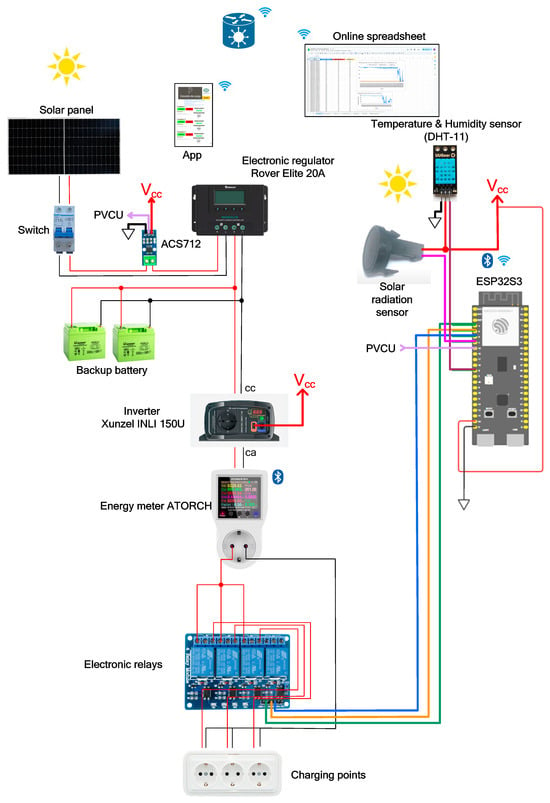
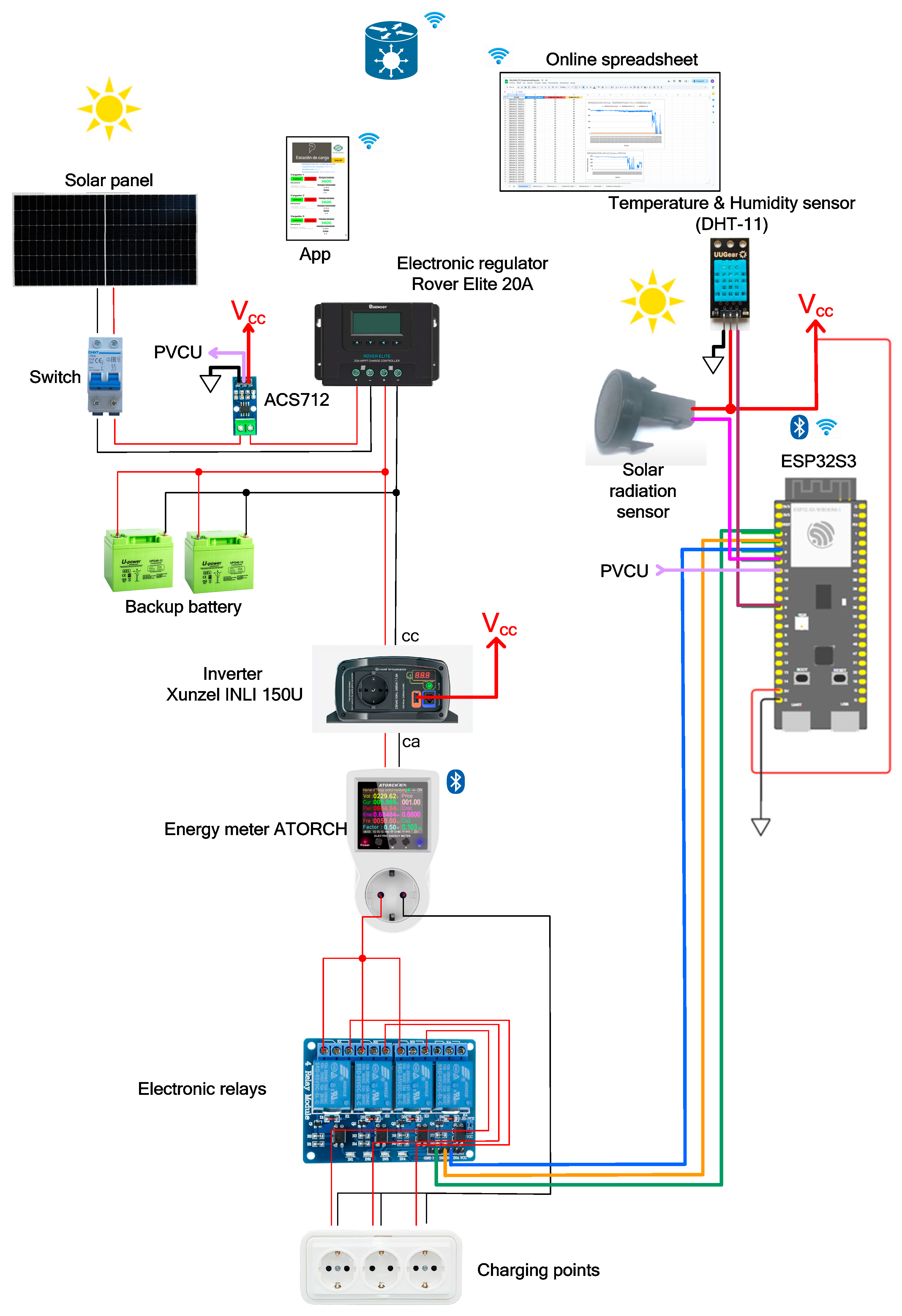
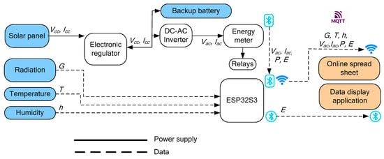
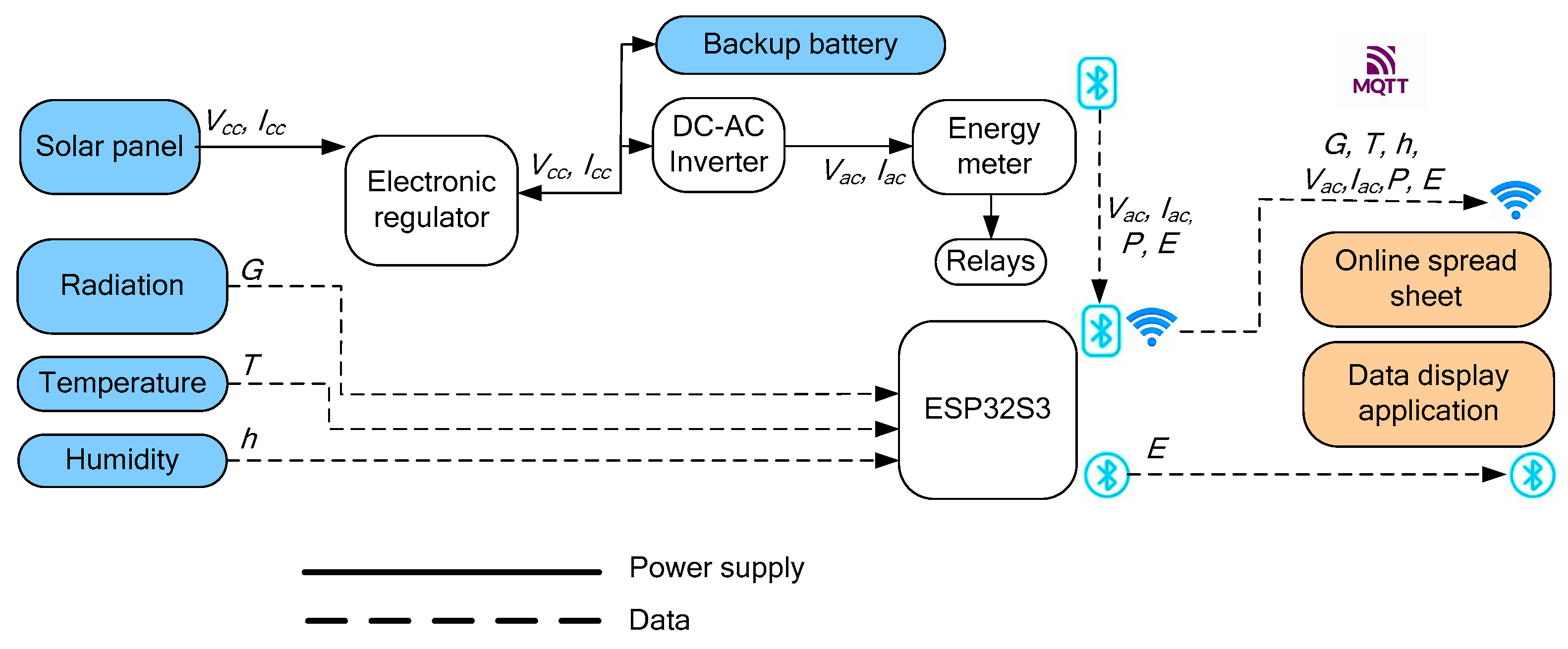
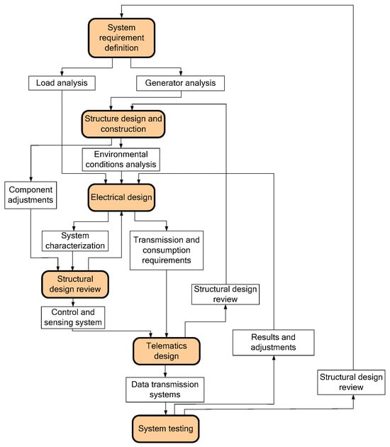
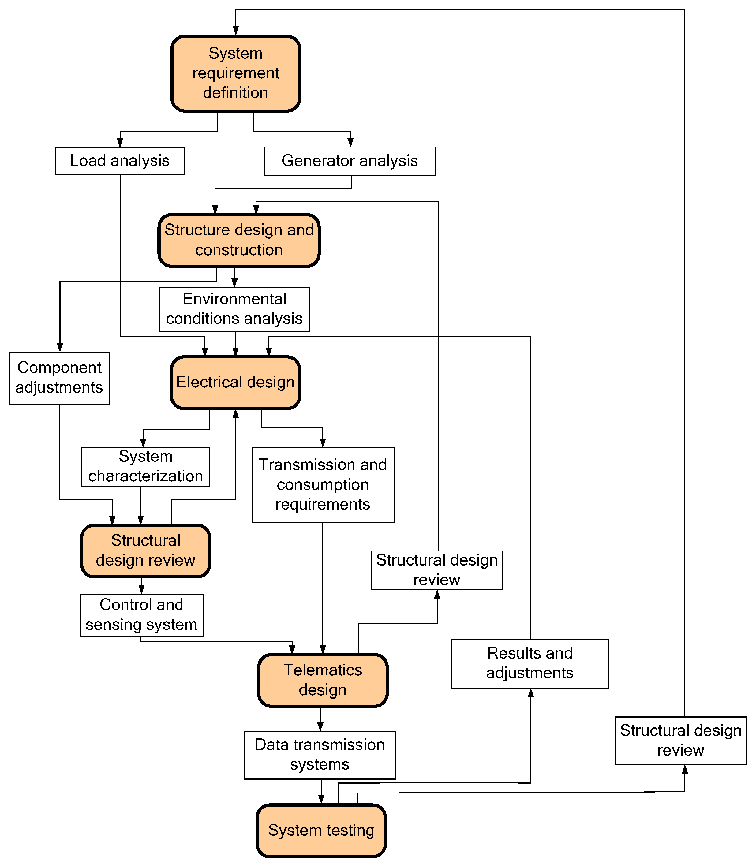
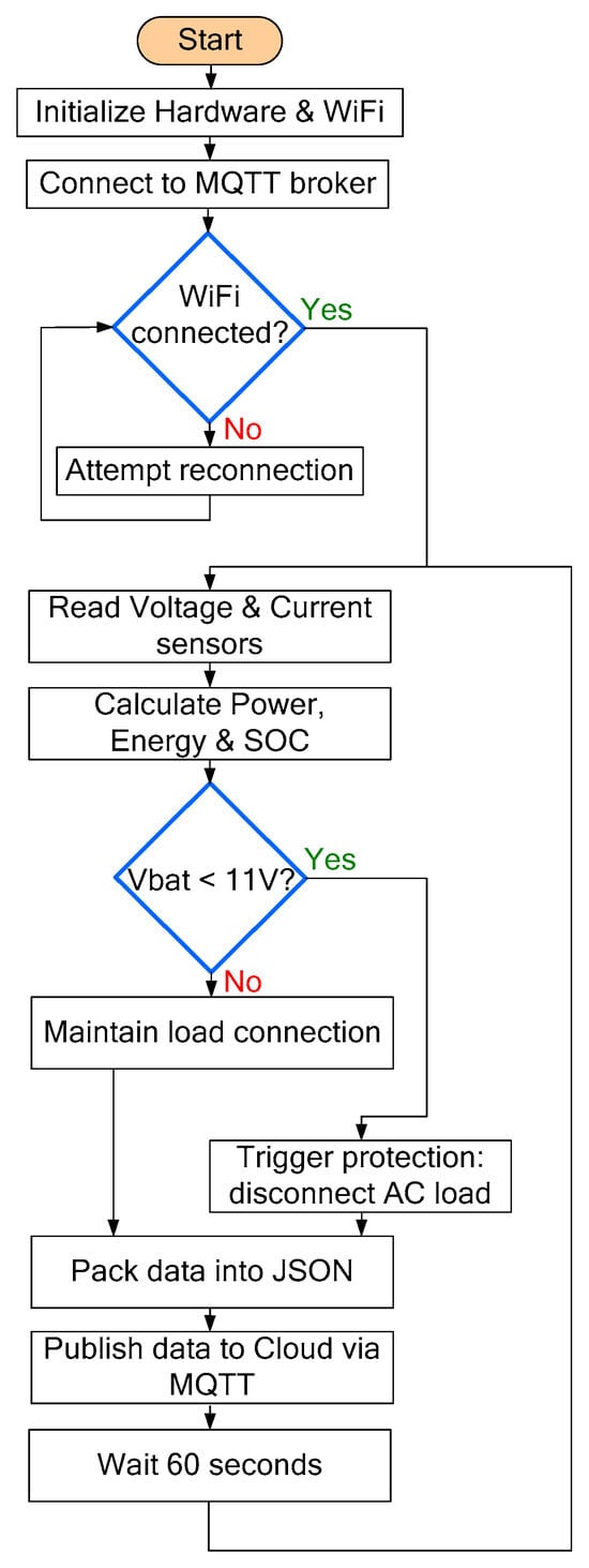
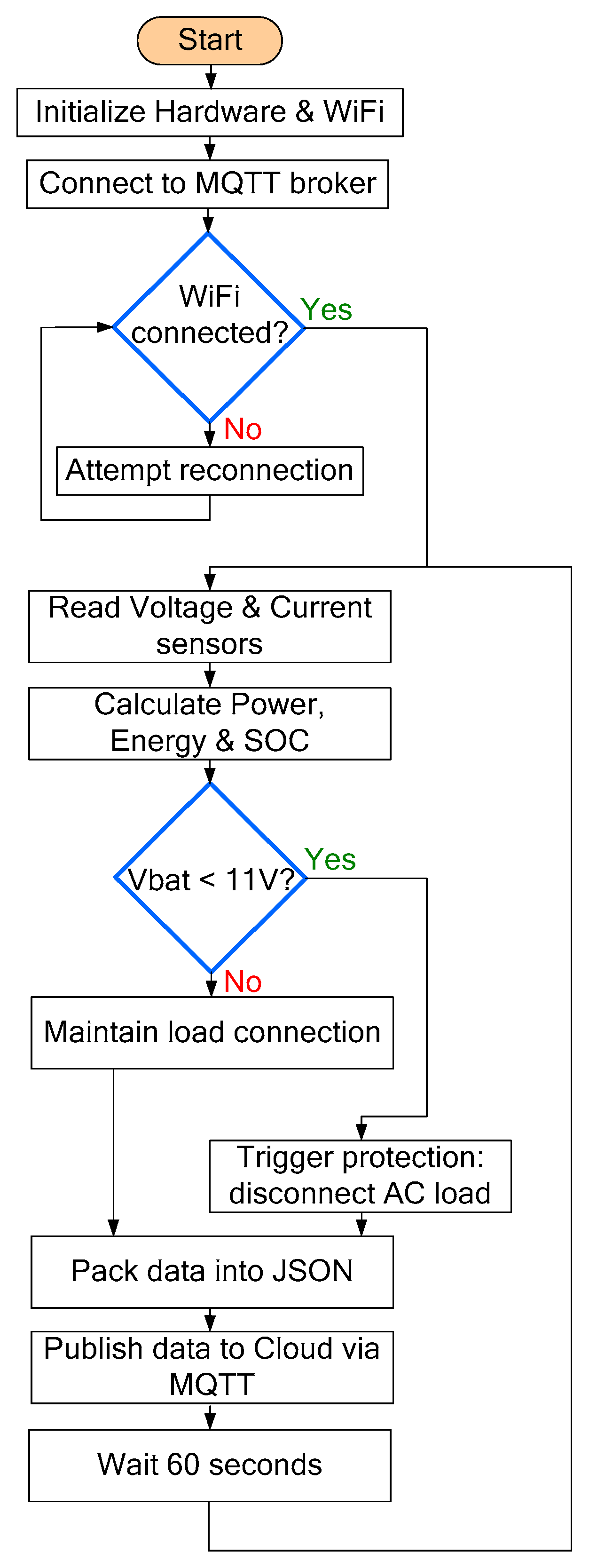
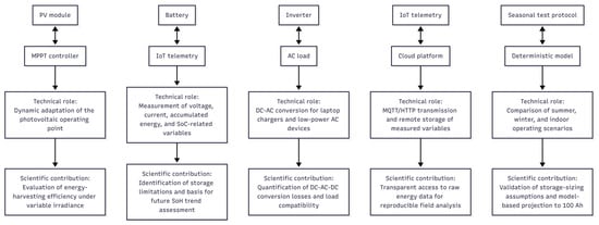
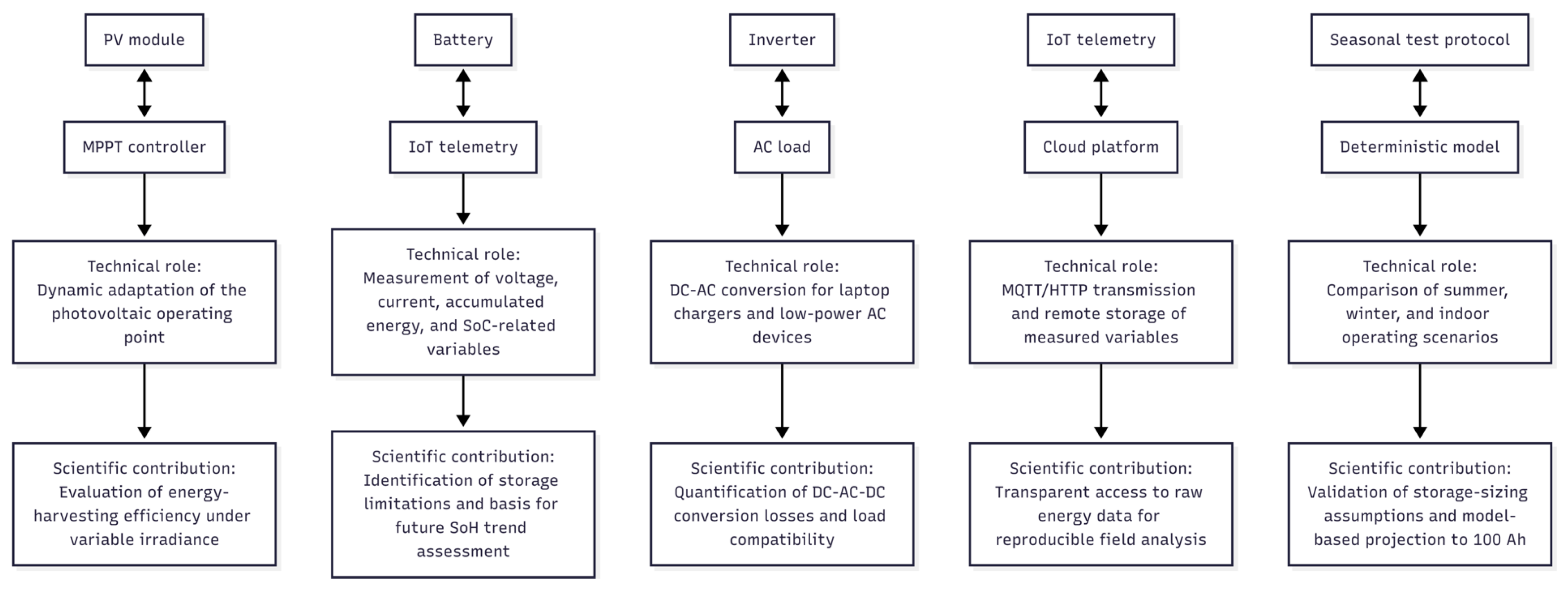
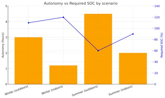
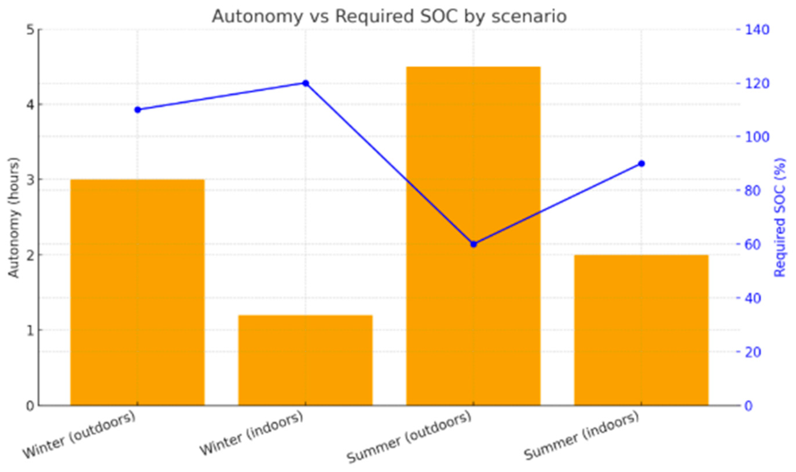
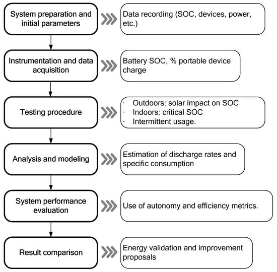
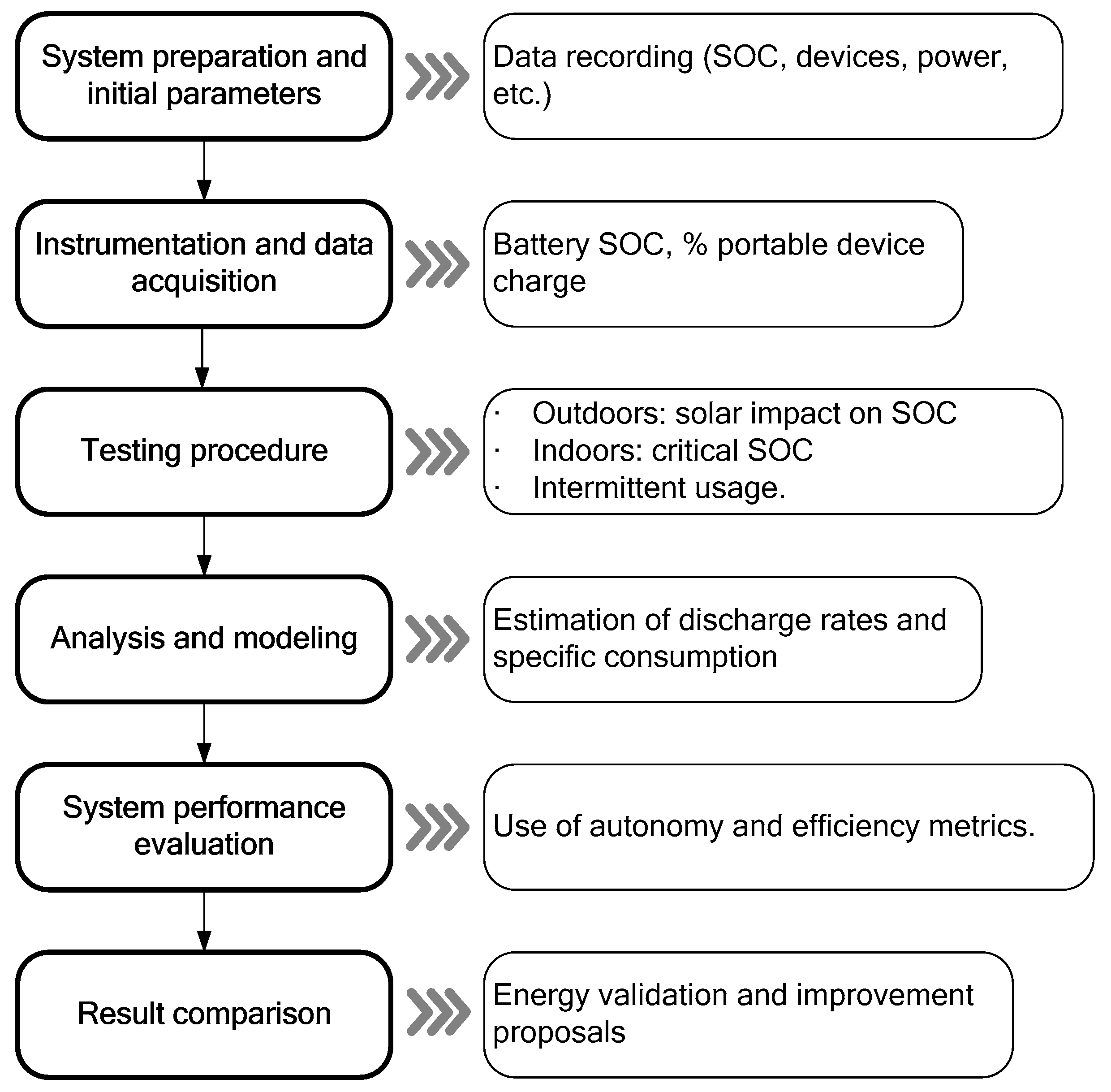
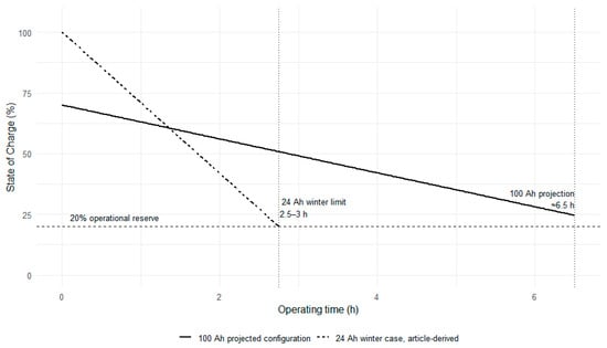
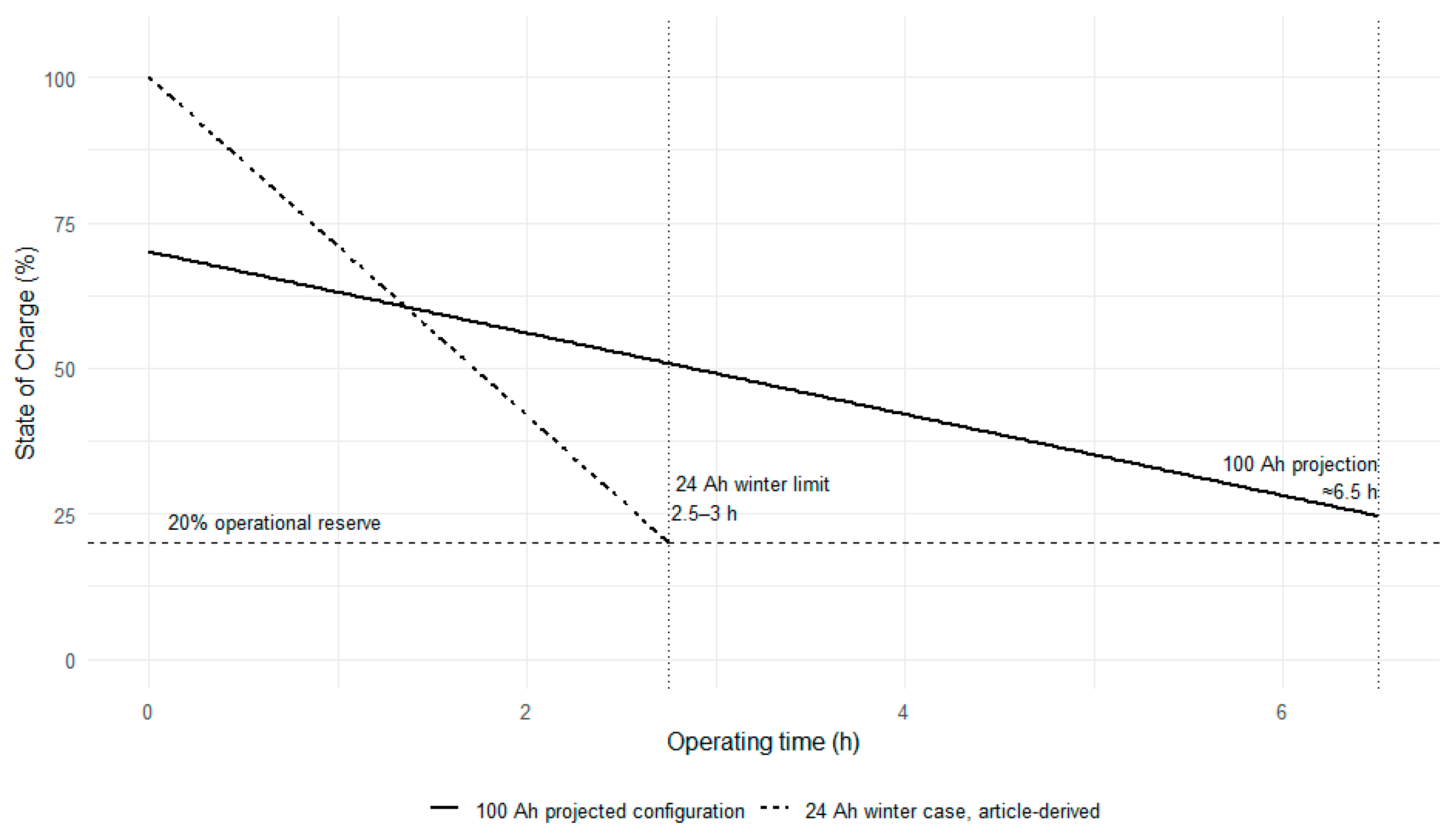
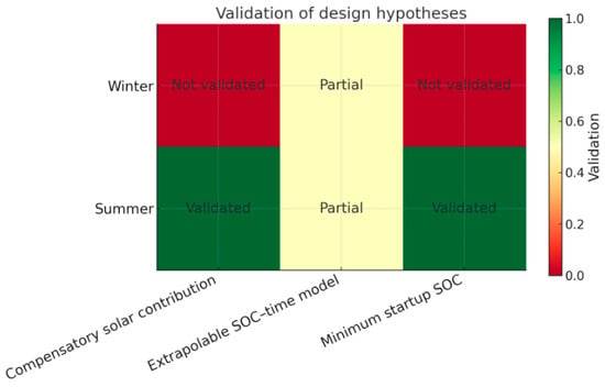
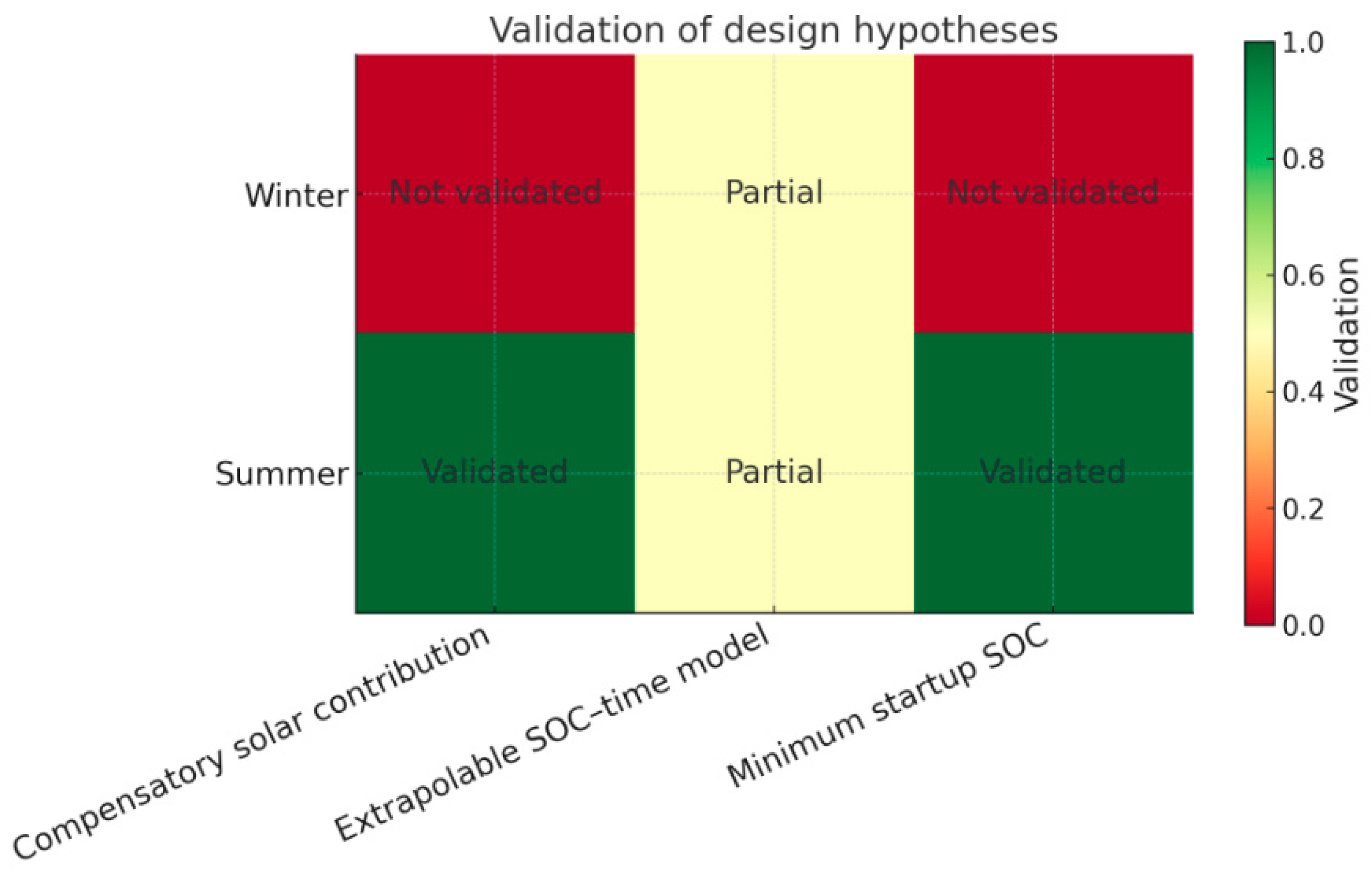

Disclaimer/Publisher’s Note: The statements, opinions and data contained in all publications are solely those of the individual author(s) and contributor(s) and not of MDPI and/or the editor(s). MDPI and/or the editor(s) disclaim responsibility for any injury to people or property resulting from any ideas, methods, instructions or products referred to in the content. |
© 2026 by the authors. Licensee MDPI, Basel, Switzerland. This article is an open access article distributed under the terms and conditions of the Creative Commons Attribution (CC BY) license.