


Abstract
In this study, the tool axis inclination angle with respect to the surface normal is used to compare the wear of spherical and toroidal milling cutters. Five different surface types were machined in this investigation using three toroidal and three spherical milling cutters at inclination angles of 15°, 35°, and 55°. Each cutter processed 45 surfaces, nine of each type. The MM1-200 microscope was used to monitor tool wear under a microscope after the surfaces had been machined. A comparison diagram and microscopic pictures of tool wear in relation to the wear surface are presented in the paper. Additionally, it contrasts the tool edge’s state at the conclusion of machining with its state following five years of storage, during which time the tool was subjected to environmental influences.
1. Introduction
Tool wear is a common phenomenon in the machining process, which directly affects machining accuracy, quality, efficiency, and economic efficiency. Monitoring tool wear can enhance finishing process efficiency, reduce machining costs, and yield positive economic benefits.
Most publications in the field discuss the experimental analysis of the wear mechanism on the ball end milling cutter [1]. In their work, Koshy et al. [2] experimentally performed the machining of hardened 1.2379 (X1655CrCoMo12) steel (58 HRC) using a spherical cutter to identify tool durability and appropriate machining parameters, based on the analysis of edge wear patterns. They concluded that the cutting, adhesion, and positioning mechanisms are all responsible for tool wear [2].
Tool wear is a continuous process and influences the dynamics of machining. Increasing cutting speed leads to increased abrasive wear, which becomes as dominant as chemical wear [3]. The increase in wear on the edge causes an intense increase in frictional forces, which leads to an increase in cutting force [4].
Extreme machining conditions that generate high temperatures at the interface between the tool and the workpiece can significantly accelerate tool wear [5]. The intensity of tool wear, in addition to its direct influence on the surface processing time, also influences the roughness of the machined surface [6,7,8,9,10,11]. A few specialized studies have established the relationship between cutting regimes and tool wear in relation to changes in surface quality [12,13,14,15,16,17,18], but those publications have not mentioned the production area with the applicability of toroidal milling cutters and spherical cutters.
Francisco argues that regular milling puts a lot of pressure on the tooth and the protective layer of the tool, so the cemented carbide and the coppering layer must be chosen carefully, because poor resistance can destroy the edges of the tool. The coating almost perfectly holds the processed material from sticking, but its durability to wear and adhesion to the base can be improved by adjustments to the machining strategy [19].
A very important factor in the process of milling a complex surface with a ball end milling cutter is the selection of the machining strategy and the angle of inclination [20].
These parameters have a significant impact on machining time, surface quality, and tool wear [21]. According to the findings in [22], the inclination angle of the machined surface, α = 0, should be avoided, because in this case, the cutting speed is equal to 0.
Schulz and Hock [23] used ball end mills at different tilt angles to study tool durability and quality of machined parts and concluded that machining at a tool tilt in the range of 10–20° is the optimal machining for fast milling in the mold manufacturing industry [23]. Tomas and Stepanka argue that tool geometry has a significant influence on the processing of CFRP materials. This study focused on investigating the effect of tool angle of action on wear, cutting forces, roughness of the machined edge, and delamination in non-contiguous milling of CFRP laminates [24].
Tool wear is commonly associated with mechanical processes that contribute to the gradual degradation of the tool; however, the influence of chemical factors should not be overlooked. Corrosive effects play a significant role in determining a tool steel’s resistance to corrosion-related wear. Over time, and depending on environmental conditions, virtually all metals are subject to corrosion to varying degrees.
Tool steels are a large group of non-alloy and alloy steels that are used in the formation of various materials in engineering, their most important feature being their durability. It is intended that the material from which the tool is made has a good resistance to wear, considering all the processes and stages that a tool goes through with various factors, including physicochemical factors. In most cases, the wear process is due to several factors combined. For example, mechanical wear is often accompanied by corrosive wear, resulting in what is referred to as mechanical–corrosive wear [25,26,27].
It is important to identify the elementary processes of tool wear, as this allows for a better prediction of the service life of the tool, as well as making their service life more efficient [27]. The evolution of the wear of the ball end mill is divided into three stages these being the initial stage, the intermediate wear stage, and the late wear stage. In the intermediate wear phase, the reworked layer becomes smoother, which increases the contact area and reduces the pressure on the surface, thus reducing the wear rate, mainly due to the formation of crescent-shaped pits. In the advanced wear stage, the quality of the powder of the ball end cutter deteriorates rapidly, generating pronounced burs at the margins, which significantly accelerate wear. At this stage, profile breakage, fragment detachment, and micro-cracking occur, leading to tool failure [28]. I agree with what the author says above, but is there not an intermediate stage before late wear?
The visible effects of wear can be damage to the edge surface of the tool and changes in the shape of its geometry, and these cause qualitative changes in the characteristics of the machined surface over time. As a result, the life of the tool is negatively affected by the intensity of the working conditions, but also by the corrosion of the working environment [26].
It is important to monitor tool wear and keep tools in good condition to avoid non-compliant surface processing. Wear is caused by both thermal and mechanical forces, which can be mitigated by operating with proper operating parameters and with the proper trajectory to spread wear along the entire length of the edge.
While each tool will eventually have some sort of wear, the effects can be delayed by paying close attention to the cutting speed, feed on the tooth, and the angle of inclination of the tool’s axis relative to what is normal on the surface. Once tool wear occurs, the protective corrosion-resistant layer is removed, exposing the worn area to further corrosion.
This paper addresses a detailed scientific analysis of milling tool wear, focusing on the comparison between three toroidal milling cutters and three spherical milling cutters used in machining a total of 45 complex surfaces with each tool. To ensure a rigorous and replicable evaluation, the machining regimes (feed rate, depth of cut, and feed) were kept constant, varying only in the angle of inclination of the tool. This variable parameter makes it possible to isolate the influence of tool geometry and angle of inclination on wear, making it easier to determine its minimum and maximum values. The main objective of the study is to quantify and compare the wear values for the two types of milling cutters, highlighting the differences in their performance and durability under surface processing conditions with complex geometries.
In addition, the paper extends the investigation into the long-term effects of corrosion on the analyzed tools. Based on the measurements made five years ago, following initial processing, new measurements will be made on the worn surfaces of the tools, which in the meantime have been exposed exclusively to ambient conditions without being reused. This stage of the study aims to evaluate corrosion-induced changes. The choice of the five-year period for storage, although seemingly arbitrary, reflects a realistic range in which corrosion can significantly affect worn surfaces and in which special tools, stored for future applications, could be reused. The results of this analysis will provide essential information on the impact of corrosion on the functional integrity of tools and the feasibility of their reuse.
This study contributes to optimizing tool selection by application and developing maintenance and storage strategies, reducing the costs associated with premature tool replacement and improving the sustainability of manufacturing processes. Through the combined approach of wear and corrosion, the work provides an integrated perspective on tool durability, with practical implications for the manufacturing industry.
2. Experimental Data
In the experimental phase, tool wear was monitored with the tool axis inclination angle—relative to the surface normal—used as the variable parameter.
To investigate the surface type effect, five types of surfaces were machined, with 27 pieces per type.
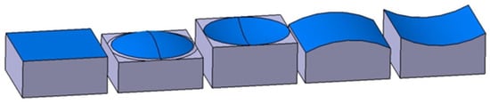
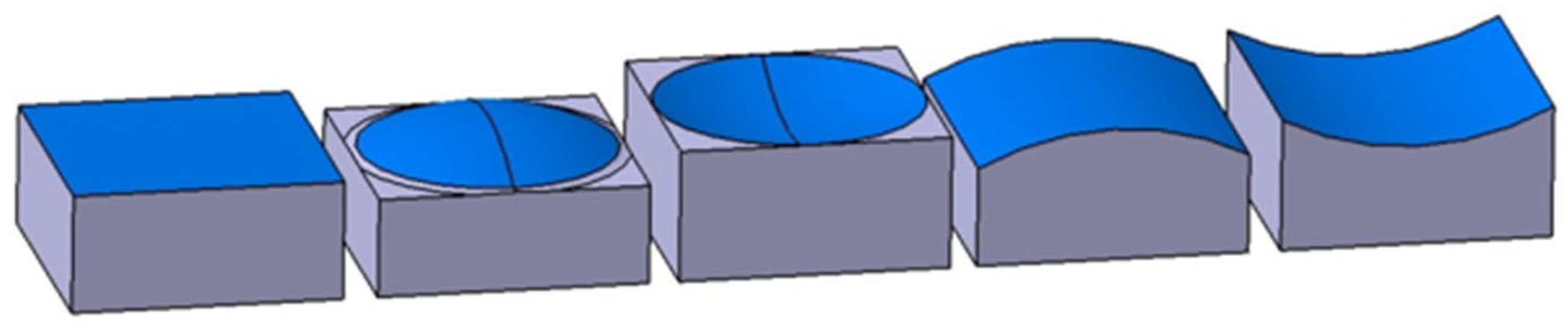
The test specimens are classified into five categories based on their physical characteristics. Experimentally, the processing of flat surfaces, the processing of spherical-convex surfaces, the processing of spherical-concave surfaces, the processing of cylindrical-convex surfaces, and the processing of cylindrical-concave surfaces will be carried out as illustrated in Figure 1.
Figure 1.
3D shape of the 5 types of surfaces.
Each specimen has a width of 40 mm, a length of 40 mm, and a thickness of 20 mm, and is made of C45 carbon steel. To guarantee consistency in the data analysis, the same materials were used for this investigation. Only the tool inclination angle was changed for each type of tool; the cutting parameters remained the same.
The flat specimen (SPLN) is a surface on which a straight line can be applied perfectly in all directions; it retains its lateral dimensions, and as a result of processing, only its height changes.
The spherical-concave surface (SFCV) is located in the upper part of the plate, symmetrically aligned with all four sides at the center of the square. The distance between the flat surface at its highest point is 5 mm, and the SFCV has a diameter of Ø85 mm.
The spherical-convex surface (SFCX) is represented by a recess in the upper part of the plate; this is positioned in the center of the plate, representing the distance of 5 mm from the maximum spherical recesses to the flat surface. The convex spherical shape has a diameter of Ø85 mm.
The cylindrical-concave surface (CICV) has a cylindrical height along the plate with a diameter of Ø85 mm and a maximum height of 5 mm.
The cylindrical-convex surface (CICX) is represented by a vertically positioned cylinder section with a depth of 5 mm, and its diameter is Ø85 mm.
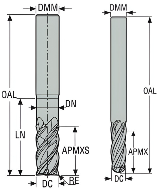
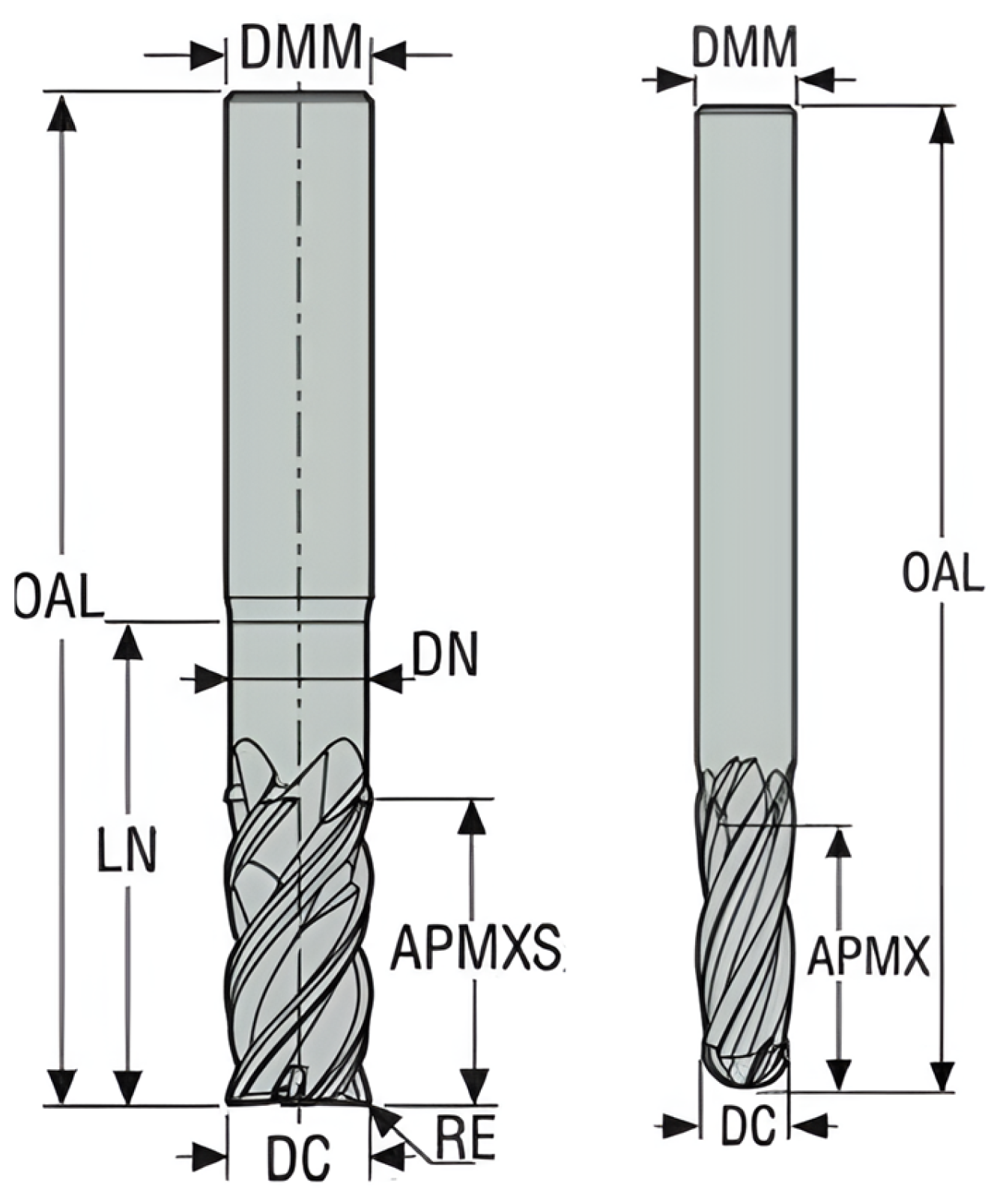
The numerical control center used is the OKUMA MU-400VA, a 5-axis machine tool. The two cutting tools used are: the JHP780160E2R400.0Z4-M64 toroidal milling cutter and the JS534160D1B.0Z4-NXT ball milling cutter.
The toroidal milling cutter or corner milling cutter has a diameter of Ø16 with a maximum cutting depth of 32 mm. Its radius at the corner is 4 mm with four teeth. This cutter is shown in Figure 2.
Figure 2.
Graphical representation of the two milling cutters.
The ball milling cutter has a diameter of Ø16 with a maximum cutting depth of 48 mm. Its radius at the corner is 8 mm with four teeth. This cutter is shown in Figure 2.
A total of three toroidal cutters and three spherical cutters were provided, analyzing the wear of the tool according to the angle at which it is used, so each tool will be used for only one type of inclination.
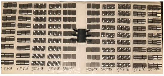
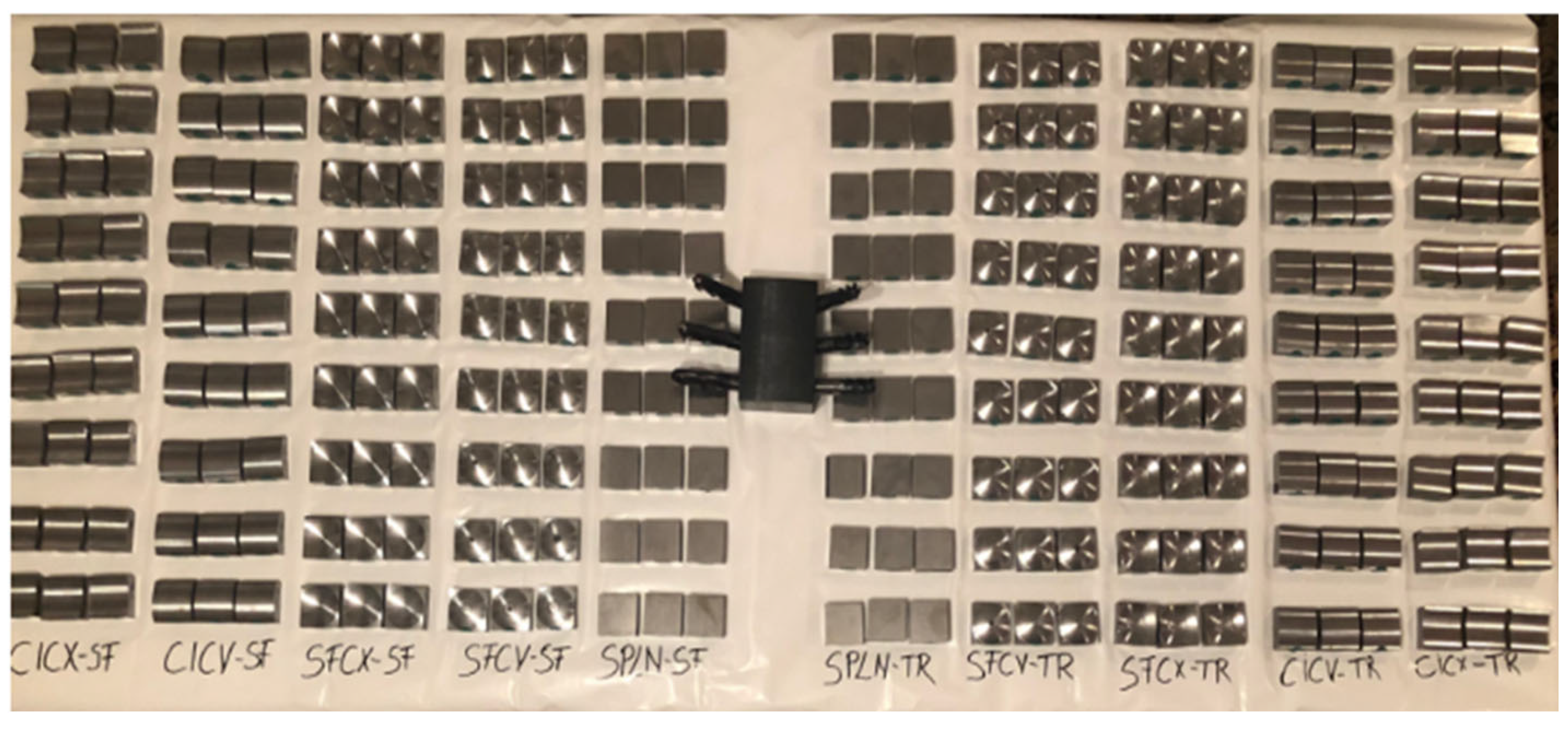
As a result, each tool will process nine types of surfaces with different geometries, totaling a number of 45 surfaces processed at the same angle, these being the totality of the processes carried out with one cutter, this number of surfaces being generated following the application of the Taguchi method. Table 1 shows the surfaces processed with the toroidal tools according to the angle, Table 2 shows the surfaces processed with the spherical cutters according to the angle of inclination, and Figure 3 shows the processed specimens.
Table 1.
Structure of a toroidal milling machine.
Table 2.
Structure of ball milling machine machining.
Figure 3.
Parts machined with the 6 milling cutters.
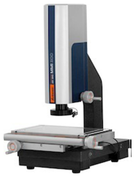
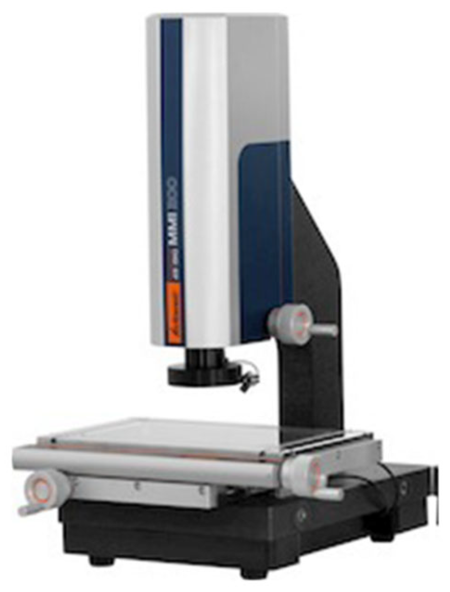
For a more precise measurement and a higher quality image, the MM1-200 microscope from Garant (Saint-François-de-la-Rivière-du-Sud, QC, Canada) was used, in the Faculty of Engineering within the North University Center in Baia Mare, illustrated in Figure 4. This is an easy-to-use, high-resolution color camera and an easy-to-use multi-touch workshop PC measuring microscope with intuitive M3 measurement software version 4, Garant. The microscope software aids in measurements and ensures their correctness by mentioning the same calibration across both measurement periods.
Figure 4.
Microscope MM1-200.
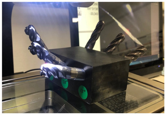
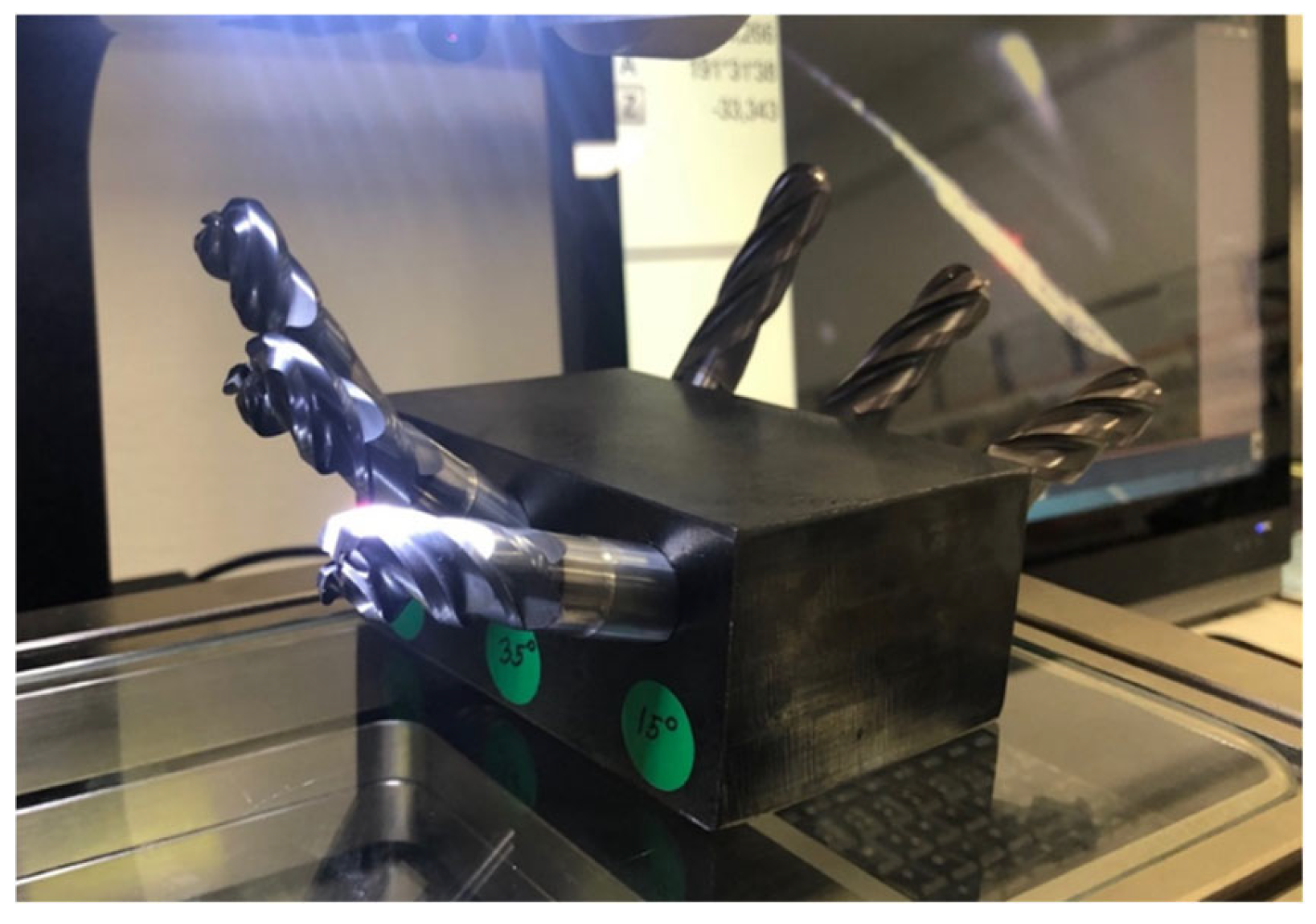
Since the microscope lacks a built-in clamping device that can be tilted to the desired angles, we designed a simple device capable of positioning and holding the tool fixed at the desired angle, namely 15°, 35°, and 55°. It has a precisely machined, angled hole that fits the cutter shank diameter and a flat surface that can be placed on the microscope table. An illustration of the cutter clamp is provided in Figure 5.
Figure 5.
Positioning the tool for measuring edge wear.
3. Experimental Results
Each type of damage will progress or occur in a variety of ways, depending on the milling conditions. As stated in ISO 8688 [29], wear-related damage should be used to evaluate a tool’s durability.
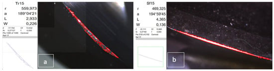
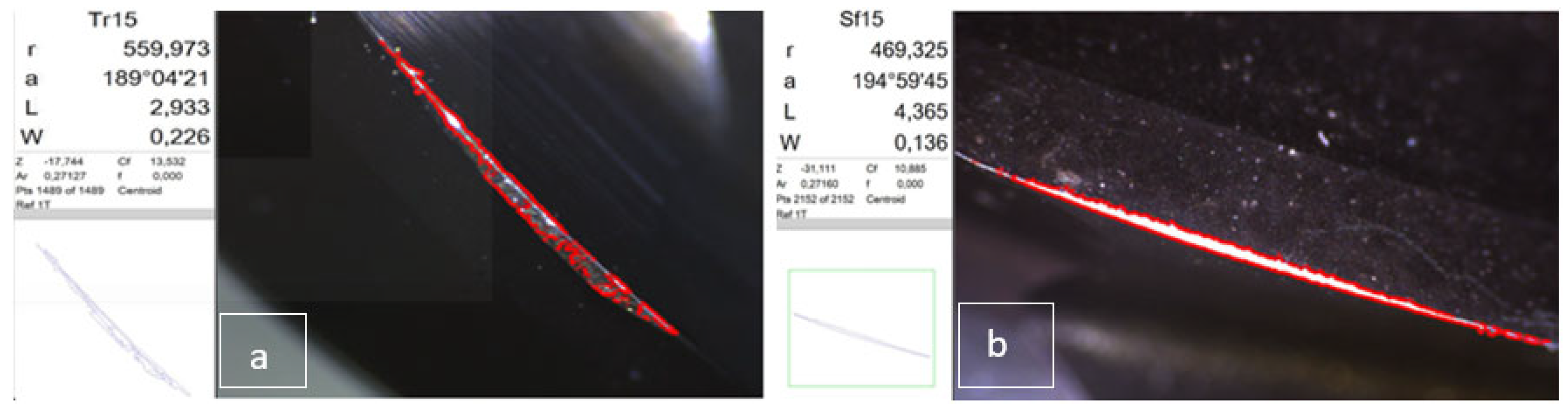
After processing the five types of surfaces at an angle of inclination of 15°, the resulting tool wear is shown in Figure 6a for the toroidal cutter and Figure 6b for the spherical cutter.
Figure 6.
Comparison of spherical and toroidal tool wear after machining at 15° angle. (a). Toroidal milling; (b). Spherical milling.
For the spherical cutter, the maximum edge wear length is 4.365 mm, with a maximum width of 0.136 mm, resulting in a total wear area of 0.2716 mm2.
With a maximum length of 2.933 mm and a maximum width of 0.226 mm, the toroidal cutter exhibits wear on the edge, with a wear surface area of 0.27127 mm2.
In this case, the values are very close, with an insignificant advantage on the side of the toroidal cutter.
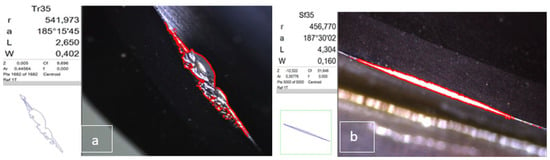
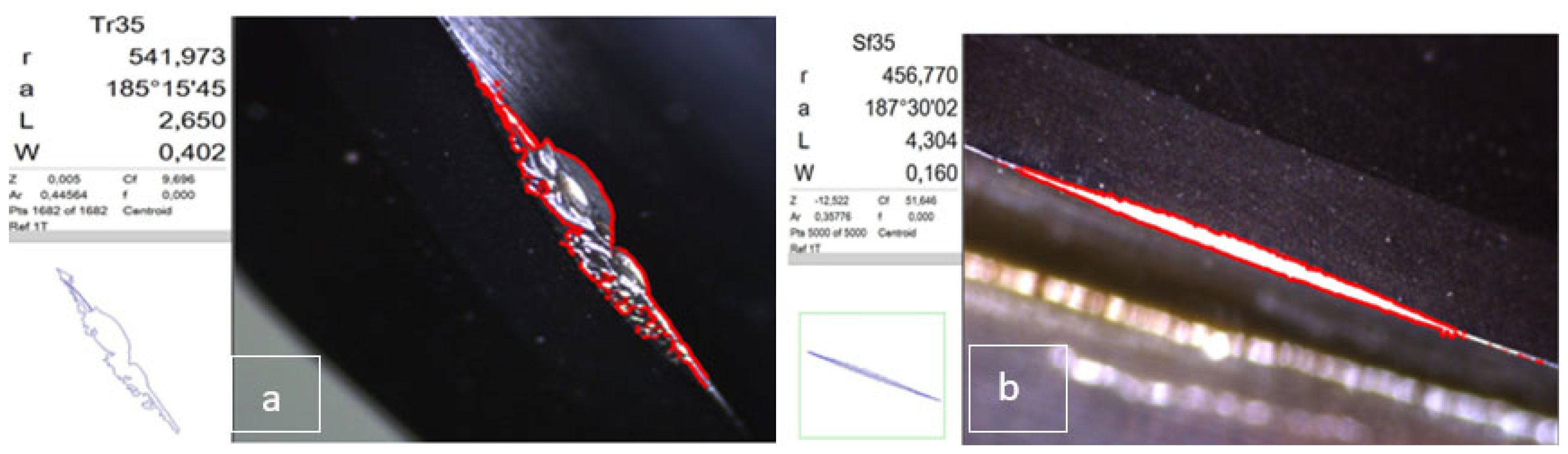
Referring to the processing of the five types of surfaces, with a constant angle of inclination of 35°, the tool wear situation is as follows.
Figure 7a shows the wear of the toroidal tool, which has a maximum length of 2.65 mm and a maximum width of 0.402 mm with an area of 0.44564 mm2.
Figure 7.
Comparison of spherical and toroidal tool wear during machining at 35° angle. (a). Toroidal milling; (b). Spherical milling.
Figure 7b shows the wear of the ball tool, having a length of 4.304 mm and a maximum width of 0.16 mm, with the total wear area being 0.35776 mm2.
In this case, the toroidal cutter achieves 0.08788 mm2 more wear on the tool edge than the ball milling cutter.
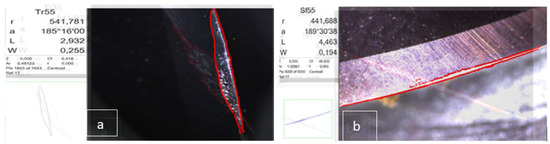
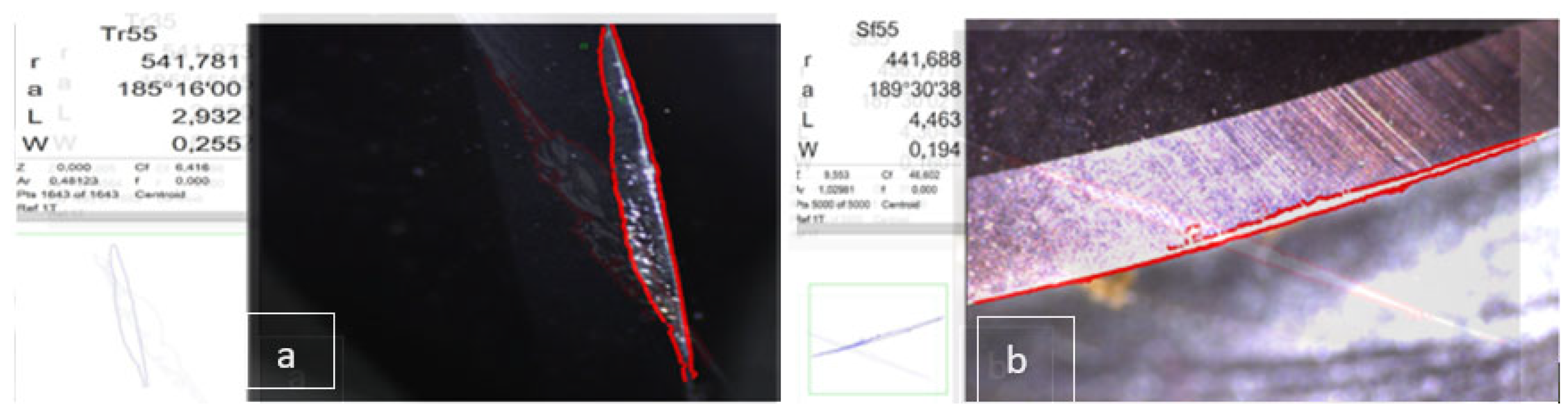
Surface processing at the 55° tool tilt angle results in tool edge wear, as shown in Figure 8. Figure 8b shows the wear of the spherical cutter with a maximum length of 4.463 mm and a maximum width of 0.194 mm, resulting in a wear area of 1.194 mm2. In Figure 8a, the wear of the toroidal cutter is shown as having a maximum length of 2.932 mm and a maximum width of 0.255 mm, resulting in a wear area of 0.48123 mm2.
Figure 8.
Comparison of spherical and toroidal tool wear during machining at an angle of 55°. (a). Toroidal milling; (b). Spherical milling.
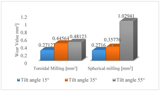
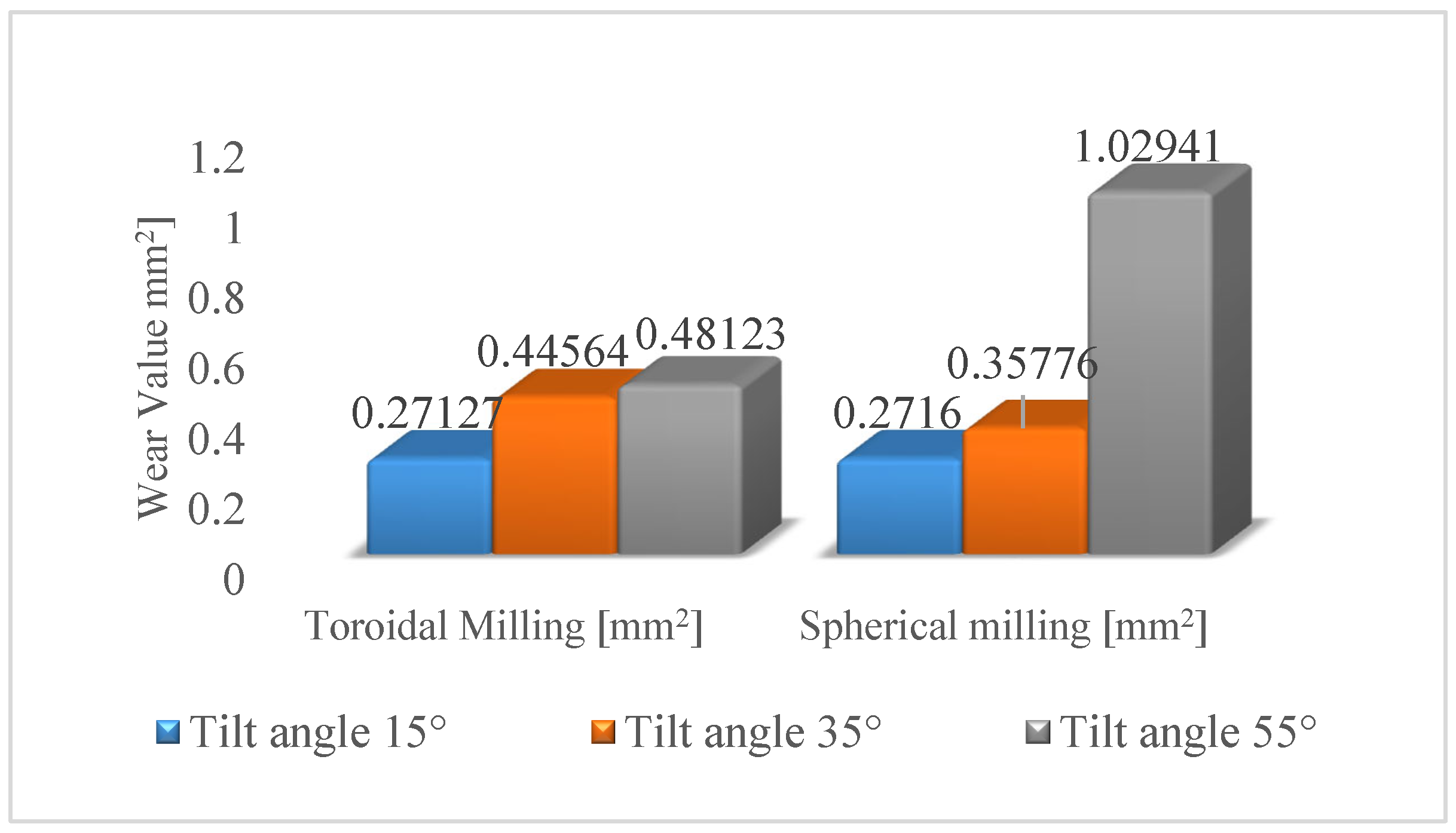
High tool wear at a 55° tilt angle, as shown in Figure 9, is the combined result of increased cutting forces, uneven stress distribution, excessive heat generation, and suboptimal chip evacuation dynamics. These conditions amplify the abrasive and thermal wear mechanisms.
Figure 9.
Graphical representation of comparative wear values between toroidal and ball milling cutters.
At a tilt angle of 55 degrees, the axial component of the cutting force increases significantly when compared to smaller angles (e.g., 15° or 35°). This results in greater pressure on the cutting edge, amplifying abrasive wear and the risk of microcracking. Additionally, at 55 degrees, the contact between the tool and the workpiece becomes more concentrated on a portion of the cutting edge, leading to localized wear. This is accentuated by the angle that does not optimize the uniform distribution of chips, unlike smaller angles, which can facilitate more efficient chip evacuation.
The spherical cutters show, on average, 38% more wear than the toroidal cutters when the wear surfaces of the two cutter types are compared. Concentrated contact, high temperatures, ineffective chip evacuation, and stronger vibrations are all blamed for this increased wear.
Toroidal cutters achieve a better balance of cutting forces (tangential, radial, and axial components) due to their larger tool–workpiece contact distribution and corner radius. This equilibrium minimizes sidewall wear and chipping by lowering the chance of vibration and focused stress.
Spherical cutters, due to the point (or linear, depending on the depth of cut) contact of the spherical edge with the workpiece, increase the axial component of the force at large angles. This leads to greater pressure on the cutting edge, amplifying abrasive wear and the risk of microcracking. Studies show that spherical cutters can generate 15–25% higher cutting forces in the axial direction compared to toroidal cutters under similar conditions.
After the completion of the initial measurements, the 6 milling cutters subjected to analysis were kept in an ambient environment, characterized by relatively constant temperature and humidity fluctuations, without being involved in processing processes, manipulated, or subjected to technical interventions. As for the temperature ranges, they are between 10 °C and 22 °C without exposure to corrosion gases, with humidity varying between 35% and 45%. Also, no corrosion protection measures were applied during exposure. These cutters were left in a state of inactivity for 5 years, during which the ambient conditions varied naturally. Currently, the wear of the cutting part will be measured again, using the same measurement methods and conditions applied at the time of the initial assessment, in order to allow an objective and precise comparison of the evolution of the wear phenomenon.
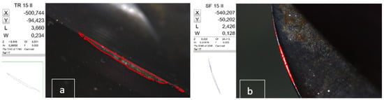
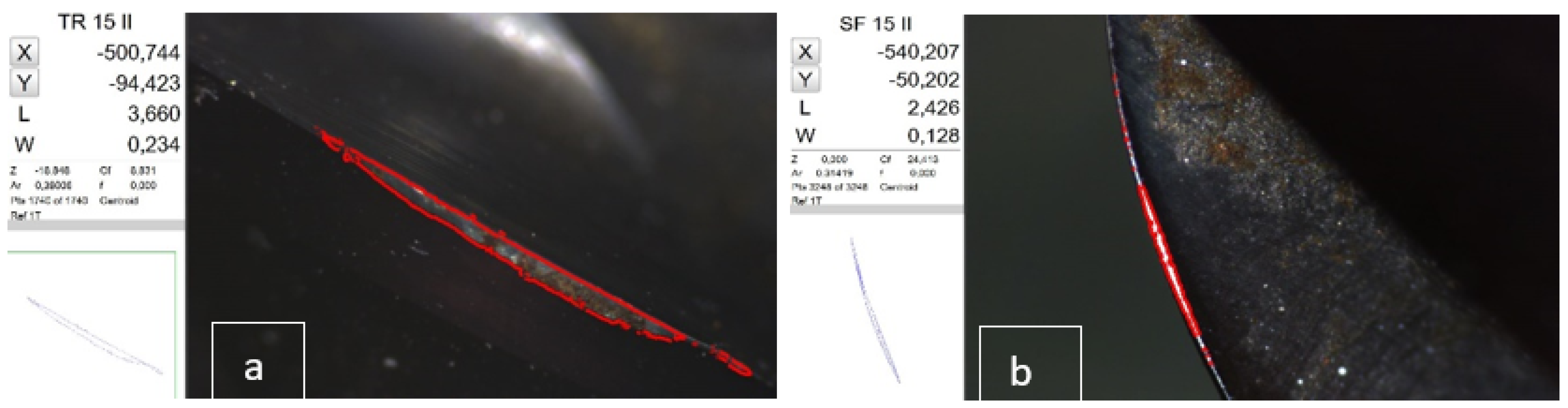
The evolution of the condition of the tool cutting part used for machining at a 15° inclination angle is shown in Figure 10. Figure 10b shows the wear of the spherical cutter with a maximum length of 2.426 mm and a maximum width of 0.128 mm, with a wear area of 0.31419 mm2. In Figure 10a, the wear of the toroidal cutter is shown as having a maximum length of 3.660 mm and a maximum width of 0.234 mm, resulting in a wear area of 0.38008 mm2.
Figure 10.
Evolution of wear of spherical and toroidal cutters used in machining with a 15° angle of inclination after five years. (a). Toroidal milling; (b). Spherical milling.
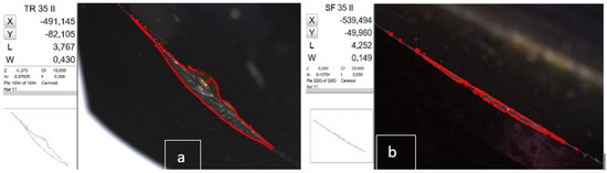
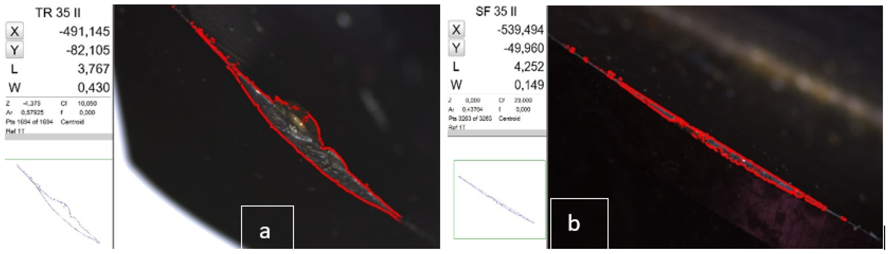
Changes in the wear of the cutting part of the tools used in machining processes at the 35° tilt angle are shown in detail in Figure 11. Figure 11b illustrates the wear of the spherical cutter, which has a maximum length of 4.252 mm and a maximum width of 0.149 mm, resulting in a wear area of 0.43704 mm2. Similarly, Figure 11a details the wear of the toroidal cutter, which has a maximum length of 3.767 mm and a maximum width of 0.430 mm, with a wear area of 0.57925 mm2.
Figure 11.
Wear Evolution of Spherical and Toroidal Milling Cutters Used in Machining with 35° Tilt Angle After Five Years. (a). Toroidal milling; (b). Spherical milling.
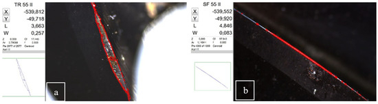
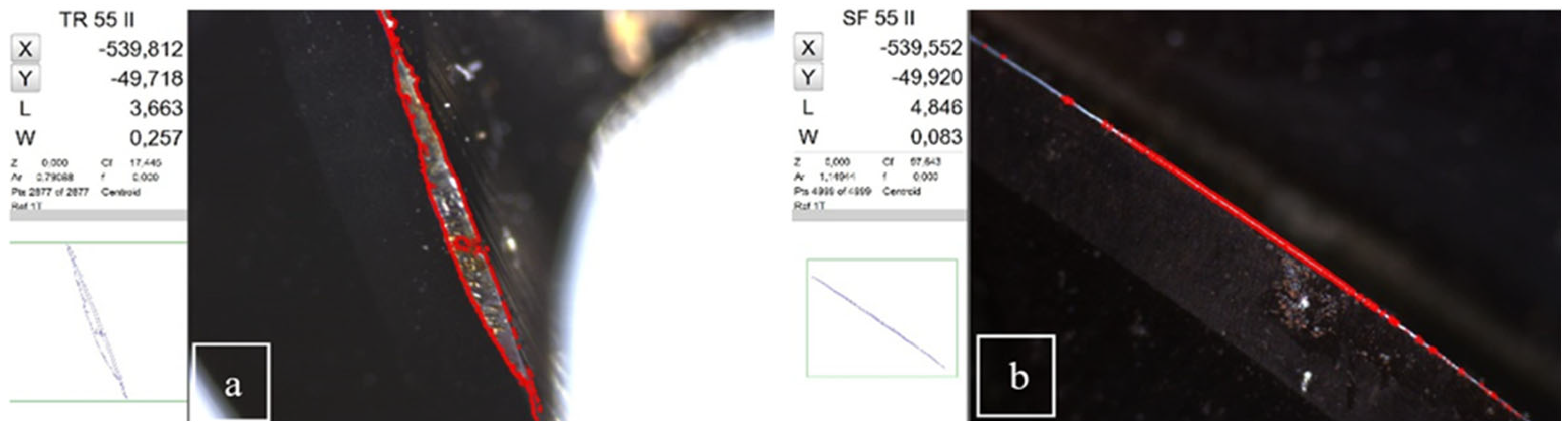
The wear transformations of the tool cutting part used in machining processes at the 55° tilt angle are shown in detail in Figure 12. In Figure 12b, the wear of the spherical cutter is illustrated, which records a maximum length of 4.252 mm and a maximum width of 0.149 mm, resulting in a wear area of 0.43704 mm2. In the same figure, in Figure 12a, the wear of the toroidal cutter is highlighted, which has a maximum length of 3.767 mm and a maximum width of 0.430 mm, and the wear area is calculated at 0.57925 mm2.
Figure 12.
Wear Evolution of Spherical and Toroidal Milling Cutters Used in Machining with a 55° Angle of Inclination After Five Years. (a). Toroidal milling; (b). Spherical milling.
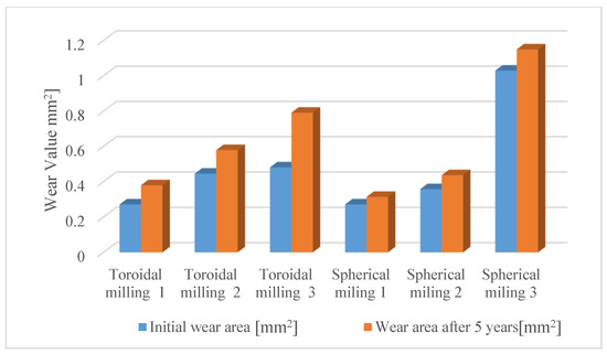
This data allows a detailed comparison of the changes suffered by the two types of cutters, highlighting values of initial wear and values of wear affected by corrosion.
Corrosion of tools stored for five years under ambient conditions (10–22 °C, 35–45% humidity) led to an increase in the area of worn surfaces, according to the measurements made and presented in Table 3. This analysis examines the mechanisms of corrosion, the effects on worn surfaces, and the nature of the process (oxidation). In the absence of metallographic analysis, observations are based on macroscopic measurements, which can confirm the increase in the area of worn surfaces but do not provide information about microstructural or chemical changes.
Table 3.
Comparison between the measured values of initial wear and tear after 5 years.
The observed corrosion is mainly a chemical reaction, in which oxidation plays a central role. Oxidation involves the reaction of the tool material, cobalt metal carbides, with oxygen in the air, forming oxides (CoO). The humidity of 35–45% facilitates the formation of a thin layer of water, which acts as an electrolyte, accelerating the process.
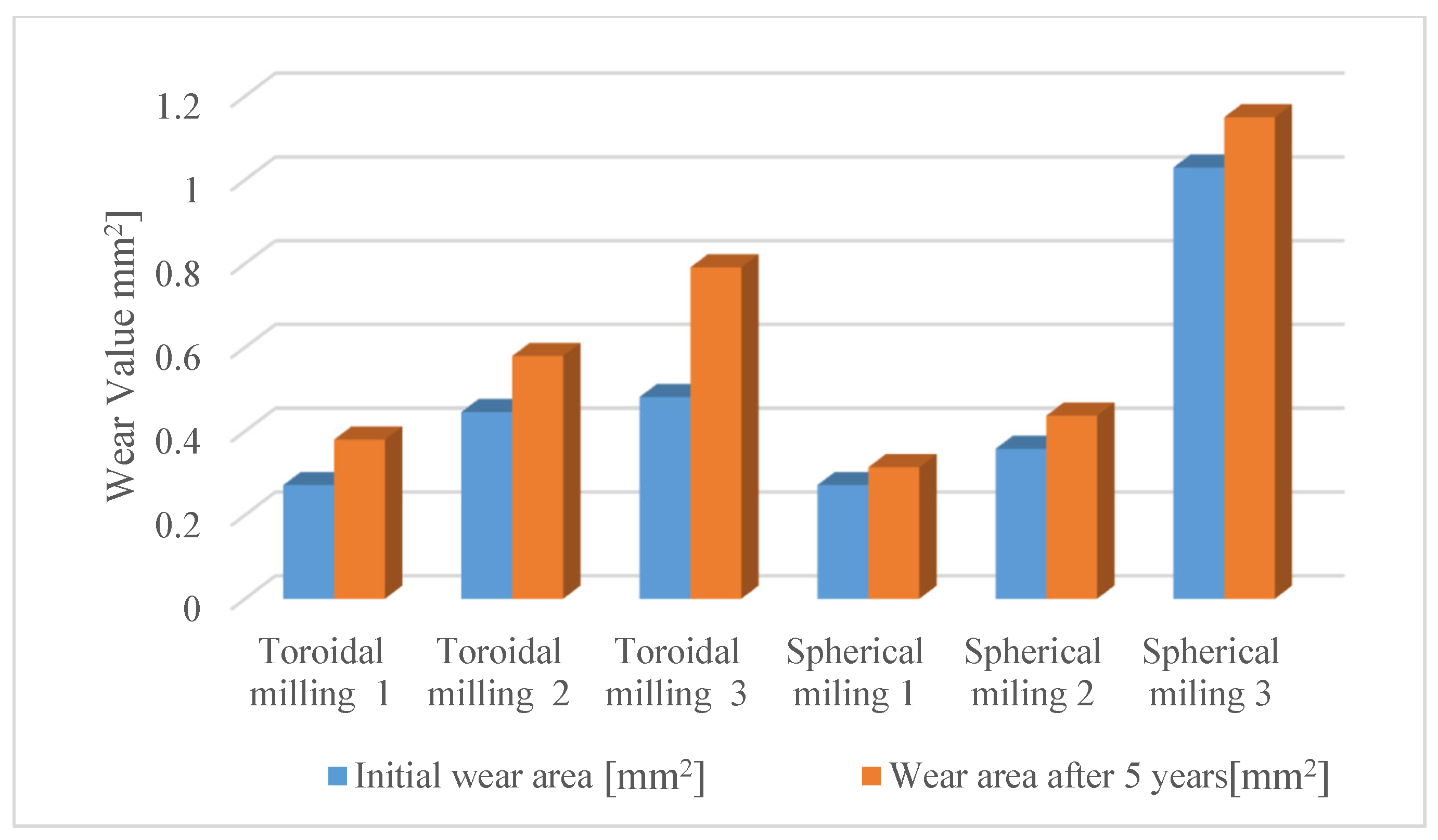
Analysis of the data presented in Table 3 and the Graph in Figure 13 reveals a significant increase in worn surface due to corrosion for all six milling cutters subjected to the experiment. The results indicate a percentage change in surface wear, with a minimum increase of 11.66% and a maximum increase of 64.34%. These values highlight the notable impact of corrosion on the worn surfaces of cutting tools, highlighting the need to take this phenomenon into account when assessing tool performance and durability.
Figure 13.
Graphical representation of measured values.
4. Conclusions
Evaluation and comparison of milling cutter wear
The main purpose of the study was to analyze and compare the degree of wear of toroidal milling cutters and ball end milling cutters in the context of processing five types of surfaces, with the tool axis inclined at three distinct angles (15°, 35°, and 55°). The research was based on experimental results, focusing exclusively on comparing tool wear, without analyzing the specific stages of wear, and taking into account only the number of machined parts. Tool wear was quantitatively assessed by measurements made with the MM1-200 microscope, which provided accurate tool degradation data after machining 45 surfaces with each cutter.
The results obtained highlighted the following:
- Differences in the degree of wear: Ball end cutters experienced a 38% higher degree of wear compared to toroidal cutters, indicating a superior strength of toroidal cutters under the tested conditions.
- Influence of tilt angle: The highest wear for both types of cutters was observed at a tilt angle of 55°. At this angle, the wear difference between the ball end mill and the toroidal cutter was 113%, which underlines the significant impact of the angle on tool performance.
- Minimal wear: The lowest wear was recorded in both types of cutters during machining at an angle of 15°, suggesting that the smaller angles reduce mechanical stresses on the tool.
Influence of corrosion on tool wear
A secondary objective of the study was to investigate the effects of corrosion on the wear of the milling cutters analyzed, especially under conditions of prolonged inactivity. Based on practical observations, tool wear has been found to include a preliminary stage of corrosive wear, which occurs before advanced mechanical wear, especially in the case of stored tools. Although mechanical wear remains the main factor in tool degradation, the effects of corrosion cannot be neglected, as they influence the geometric stability of the tool edge and, implicitly, its durability.
In the context of corrosion analysis, it was observed that tools used intensively and then stored for a long term (five years) in unfavorable environmental conditions have the following characteristics:
- Stagnation of wear: Regardless of the initial degree of wear, after the period of inactivity, there has been no significant progress in mechanical wear, this being replaced by the effects of corrosion.
- Corrosion wear variation: The increase in wear due to corrosion ranged from 11.66% to 64.34%, with an average of 30.64%. Notably, the milling cutter with the highest initial mechanical wear exhibited the least increase in corrosive wear, indicating a complex interaction between mechanical and corrosive wear.
- Impact of inactivity: Prolonged inactivity has a significant impact on the condition of the tool edge, especially in the case of tools with special specifications, which are often stored for future use in complex machining.
Practical recommendations
Although new tools are protected by anti-corrosion coatings, the initial mechanical wear compromises these layers, exposing tool surfaces to corrosion. Therefore, it is recommended to use tools until the permissible wear limit is reached in order to minimize the effects of corrosion during storage and maximize their operational efficiency. This practice is particularly relevant for tools with common specifications, which are frequently used in production, but also for special tools, which can be subjected to long periods of inactivity.
Author Contributions
Conceptualization, A.O.; methodology, A.O.; software, A.O.; validation, M.B. and A.O.; formal analysis, A.O.; data curation, A.O.; writing—original draft preparation, A.O.; writing—review and editing, M.B.; visualization, M.B.; supervision, M.B. All authors have read and agreed to the published version of the manuscript.
Funding
This research received no external funding.
Institutional Review Board Statement
Not applicable.
Informed Consent Statement
Not applicable.
Data Availability Statement
All data supporting the findings of this study are included within the article.
Conflicts of Interest
The authors declare no conflict of interest.
References
- Ben Said, M.; Saï, K.; Saï, W.B. An investigation of cutting forces in machining with worn ball-end mill. J. Mater. Process. Technol. 2009, 209, 3198–3217. [Google Scholar] [CrossRef] [Scilit]
- Koshy, P.; Dewes, R.C.; Aspinwall, D.K. High speed end milling of hardened AISI D2 tool steel (58 HRC). J. Mater. Process. 2009, 127, 266–273. [Google Scholar] [CrossRef] [Scilit]
- Sokovic, M.; Kopac, J.; Dobrzanski, L.A. Wear of PVD-coated solid carbide end mills in dry high-speed cutting. J. Mater. Process. Technol. 2004, 157, 422–426. [Google Scholar] [CrossRef] [Scilit]
- Ko, T.J.; Kim, H.S.; Lee, S.S. Selection of the machining inclination angle in high-speed ball end milling. Int. J. Adv. Manuf. Technol. 2001, 17, 163–170. [Google Scholar] [CrossRef] [Scilit]
- Krolczyk, G.M.; Nieslony, P.; Legutko, S. Determination of tool life and research wear during duplex stainless steel turning. Arch. Civ. Mech. Eng. 2015, 15, 347–354. [Google Scholar] [CrossRef] [Scilit]
- Krolczyk, G.; Legutko, S.; Nieslony, P. Study of the surface integrity microhardness of austenitic stainless steel after turning. Teh. Vjesn. 2014, 21, 1307–1311. [Google Scholar]
- Osan, A.; Banica, M.; Nasui, V. The influence of inclination of the axis of the toroidal on a flat surface roughness. In Proceedings of the 23nd edition of Innovative Manufacturing Engineering&Energy International Conference—ImanE&E 2019, Pitești, Romania, 22–24 May 2019. [Google Scholar]
- Oşan, A.; Bănică, M.; Năsui, V.; Slătineanu, L.; Merticaru, V.; Mihalache, A.; Dodun, O.; Ripanu, M.; Nagit, G.; Coteata, M.; et al. Processing of Convex Complex Surfaces with Toroidal Milling Versus Ball Nose End Mill. MATEC Web Conf. 2018, 178, 01003. [Google Scholar] [CrossRef] [Scilit]
- Przestacki, D.; Jankowiak, M. Surface roughness analysis after laser assisted machining of hard to cut materials. J. Phys. Conf. Ser. 2014, 483, 012019. [Google Scholar] [CrossRef] [Scilit]
- García-Hernández, C.; Valdivia-Sánchez, J.-J.; Ubieto-Artur, P.; García-Arbués, M.; Tzotzis, A.; Garde-Barace, J.-J.; Valdivia-Calvo, F.; Huertas-Talón, J.-L. Improved Use of the Full Length of Milling-Tool Flutes in Processes of Air-Contour Milling. J. Manuf. Mater. Process. 2025, 9, 150. [Google Scholar] [CrossRef] [Scilit]
- Zhang, X.; Li, Z.; Zhang, B.; Wang, J.; Elmi, S.A.; Bai, Z. Optimization and Finite Element Simulation of Wear Prediction Model for Hot Rolling Rolls. Metals 2025, 15, 456. [Google Scholar] [CrossRef] [Scilit]
- Hioki, D.; Diniz, A.E.; Sinatora, A. Influence of HSM cutting parameters on the surface integrity characteristics of hardened AISI H13 steel. J. Braz. Soc. Mech. Sci. Eng. 2013, 35, 537–553. [Google Scholar] [CrossRef] [Scilit]
- Magri, M.L.; Diniz, A.E.; Button, S.T. Influence of surface topography on the wear of hot forging dies. Int. J. Adv. Manuf. Technol. 2012, 65, 459–471. [Google Scholar] [CrossRef] [Scilit]
- Sadilek, M.; Kratochvi, J.; Petru, J. Cutting tool wear monitoring with the use of impedance layers. Teh. Vjesn. 2014, 21, 639–644. [Google Scholar]
- He, Z.; Shi, T.; Chen, X. An Innovative Study for Tool Wear Prediction Based on Stacked Sparse Autoencoder and Ensemble Learning Strategy. Sensors 2025, 25, 2391. [Google Scholar] [CrossRef] [Scilit]
- Castañeda-Quilcaro, F.D.; Cordova-Yavar, C.L.; Vidal Endara, R.F. Product Design to Improve the Measurement and Projection of Mill Liner Wear. Eng. Proc. 2025, 83, 4. [Google Scholar]
- de Lacalle, L.N.L.; Lamikiz, A.; Muñoa, J.; Salgado, M.A.; Sanchez, J.A. Improving the high-speed finishing of forming tools for advanced high-strength steels (AHSS). Int. J. Adv. Manuf. Technol. 2006, 29, 49–63. [Google Scholar] [CrossRef] [Scilit]
- Urbikain, G.; López de Lacalle, L.N. Modelling of surface roughness in inclined milling operations with circle-segment end mills. Simul. Model. Pract. Theory 2018, 84, 161–176. [Google Scholar] [CrossRef] [Scilit]
- Silva, F.J.G.; Martinho, R.P.; Magalhães, L.L.; Fernandes, F.; Sales-Contini, R.C.M.; Durão, L.M.; Casais, R.C.B.; Sousa, V.F.C. A Comparative Study of Different Milling Strategies on Productivity, Tool Wear, Surface Roughness, and Vibration. J. Manuf. Mater. Process. 2024, 8, 115. [Google Scholar] [CrossRef] [Scilit]
- Wojciechowski, S. Machined surface roughness including cutter displacements in milling of hardened steel. Metrol. Meas. Syst. 2011, 18, 429–440. [Google Scholar] [CrossRef] [Scilit]
- Toh, C.K. A study of the effects of cutter path strategies and orientations in milling. J. Mater. Process. Technol. 2004, 152, 346–356. [Google Scholar] [CrossRef] [Scilit]
- Tonshoff, H.K.; Arendt, C.; Ben Amor, R. Cutting of hardened steel. Cirp Ann. 2000, 49, 547–566. [Google Scholar] [CrossRef] [Scilit]
- Schulz, H.; Hock, S. High-speed milling of die and moulds—Cutting conditions and technology. Ann. CIRP 1995, 44, 35–38. [Google Scholar] [CrossRef] [Scilit]
- Knápek, T.; Dvořáčková, Š.; Váňa, M. The Effect of Clearance Angle on Tool Life, Cutting Forces, Surface Roughness, and Delamination during Carbon-Fiber-Reinforced Plastic Milling. Materials 2023, 16, 5002. [Google Scholar] [CrossRef] [Scilit] [PubMed]
- Zwierzycki, W.; Stachowiak, A.; Górny, K. Material selection for knife to cutting bell pepper. Tribocorrosion Res. Tribol. 2013, 5, 139–148. [Google Scholar]
- Beer-Lech, K.; Surowska, B. Research on resistance to corrosive wear of dental CoCrMo alloy containing post- production strap. Eksploat. I Niezawodn. Maintenace Reliab. 2015, 17, 90–94. [Google Scholar] [CrossRef] [Scilit]
- Gauvent, M.; Rocca, E.; Meausoone, P.J.; Brenot, P. Corrosion of Materials Used as Cutting Tools of Wood. Wear 2006, 261, 1051–1055. [Google Scholar] [CrossRef] [Scilit]
- Zhang, Y.; Fu, Y.; Li, Q.; Zhang, K.; Liu, K. Study on the Cutting Performance and Remaining Life Prediction of Micro-Texture Ball End Milling Cutters for Titanium Alloys. Coatings 2024, 14, 814. [Google Scholar] [CrossRef] [Scilit]
- ISO 8688; Tool Life Testing Milling. International Organization for Standardization: Geneva, Switzerland, 1989.

Disclaimer/Publisher’s Note: The statements, opinions and data contained in all publications are solely those of the individual author(s) and contributor(s) and not of MDPI and/or the editor(s). MDPI and/or the editor(s) disclaim responsibility for any injury to people or property resulting from any ideas, methods, instructions or products referred to in the content. |
© 2025 by the authors. Licensee MDPI, Basel, Switzerland. This article is an open access article distributed under the terms and conditions of the Creative Commons Attribution (CC BY) license (https://creativecommons.org/licenses/by/4.0/).