


Abstract
The article presents a description of models and results of research on separate and joint effects of unbalanced and non-linear loads on the operation of a lower-power synchronous generator. The modeling of the generator included automatic regulators of excitation and rotor speed. For our studies, we used computer models built in the MATLAB environment and the Fazonord package, as well as a physical model of a low-power synchronous generator. The simulation results attested to the occurrence of the following negative effects: there was a noticeable negative sequence current, the generator began to emit higher harmonics into the network, and the amplitude of forced oscillations of the excitation current increased. The presence of these effects can lead to additional mechanical vibrations of the rotor, accelerated wear of the equipment, and loss of stability. To ensure that low-power generators can operate in the presence of unbalance and harmonic distortion, it is necessary to limit their load. The maximum phase current difference, which must not exceed 12% of the nominal current, can be used as a criterion. Furthermore, when distributed generation units serve non-linear and unbalanced loads, it is necessary to implement special measures to protect the generating equipment: the use of direct current links, the use of harmonic filters, the installation of generator protections limiting negative sequence current, the use of automatic excitation current limitation, etc.
1. Introduction
In order to improve the flexibility and resilience of electric power systems (EPS), a transition is underway from the construction of large power units to the large-scale adoption of distributed generation (DG) facilities installed near power consumers [1,2,3]. This approach is also applicable to railroad power supply systems (RPSSs). The use of DG units in RPSSs will make it possible to cut the costs of power supply of railway transport infrastructure facilities, increase the reliability of power supply, and improve the power quality [4,5,6], including in areas of power supply to non-traction loads. However, certain features unique to load flows of RPSSs that are related to the markedly variable nature of traction loads, the presence of unbalance and harmonic distortions, complicate the operating conditions of synchronous machines of DG units.
In the presence of an unbalanced load, the stator windings of a synchronous machine have negative sequence currents flowing through them, resulting in a magnetic flux that rotates relative to the rotor at double angular velocity. This flux induces double frequency currents in the rotor winding, resulting in additional losses. Moreover, an electromagnetic torque pulsing at double frequency is created, which causes additional vibrations as well as harmonic distortions of stator and rotor voltages and currents. Therefore, there is a need to limit the capacity of the generator and the duration of its operation under reduced power quality. Even a slight increase in current unbalance requires a significant reduction in the generator’s full-load runtime.
The appearance of harmonic distortions [7,8] leads to a decrease in the power factor, which can cause the rotor current to increase as a result of the action of the automatic regulator of excitation. In general, the occurrence of higher harmonics in the stator windings of a synchronous machine is the subject of many studies, for example, [9,10,11,12,13,14]. From the analysis of the reviewed works it follows that the generation of higher harmonics in stator voltages depends on the type of its winding [10,11], the shape of the cores [12] and the degree of their saturation, and the availability of damper windings [13], as well as on the excitation current control system of the generator [14].
Studies of load flows of generators under a reduced power quality, the results of which were reported in papers [15,16,17,18], allowed the significant expansion of the scope of the use of asynchronous and unbalanced load flows in practical applications. The general principle governing the application of generators under such conditions, formulated in [16] and consisting in limiting the continuous load of the synchronous generator when there is an unbalance and harmonic distortion, still holds valid today. Methods for assessing the effect of load unbalance with a non-sine waveform of current were based on the fact that the effect of the negative-synchronous field and the fields of higher-harmonic current of the stator lead to the same effect, i.e., extra heating of the active parts of the generator. These conclusions are confirmed by a study carried out in [19] on the calculation of the permissible load of a synchronous generator with different shares of power consumers with a non-linear current–voltage characteristic. In [20], a method is proposed to reduce the influence of higher-current harmonics on the operation mode of synchronous hydrogenerators, and the permissible generated power of a synchronous hydrogenerator when operating on a non-sinusoidal load is determined. In such modes, it is mandatory to use thermal protection of the synchronous generator, taking into account the harmonic distortion of the stator and rotor currents. For example, in [21], a new model of thermal protection of the rotor of a synchronous generator is presented, taking into account the simultaneous occurrence of rotor overload due to the excitation current and rotor overload due to the negative sequence current.
The studies in [22,23] investigate the effects of non-linear and asymmetric loads in isolated synchronous generators. Reference [22] presents an analysis of the oscillations caused by an asymmetric load of an isolated synchronous generator. In [23], a study of the disturbances caused by harmonic distortions in the synchronous and asynchronous generators during their parallel operation in an isolated system is presented.
Recently, there have been certain changes in EPSs and RPSSs. The number of power semiconductors and other non-linear components used has increased. Particularly significant progress has been made in the area of creating effective means of automatic regulation of excitation (ARE) and rotor speed (ARS) of the generator. Therefore, studies of the effects of unbalance and non-sine waveforms on the operation of a low-power synchronous generator prove relevant. The purpose of this study is to determine the effect of unbalanced and non-linear loads on the operation of low-power synchronous machines equipped with modern types of ARE and ARS. For our studies we used computer models built in the MATLAB environment and the Fazonord package [24], as well as a physical model of a low-power synchronous generator.
The main contribution and value of this work is the study of the separate and combined effects of a non-linear and asymmetric load of an isolated low-power synchronous generator or a generator operating as part of an RPSS. At the same time, the main attention is focused on the influence of these modes on the operation of the modern ARE and ARS of a synchronous generator.
Below is a description of the models and the results of research on separate and joint influence of unbalanced and non-linear loads on the operation of a lower-power synchronous machine.
2. Unbalanced Load Effect on Operation of a Low-Power Synchronous Machine
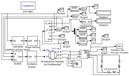
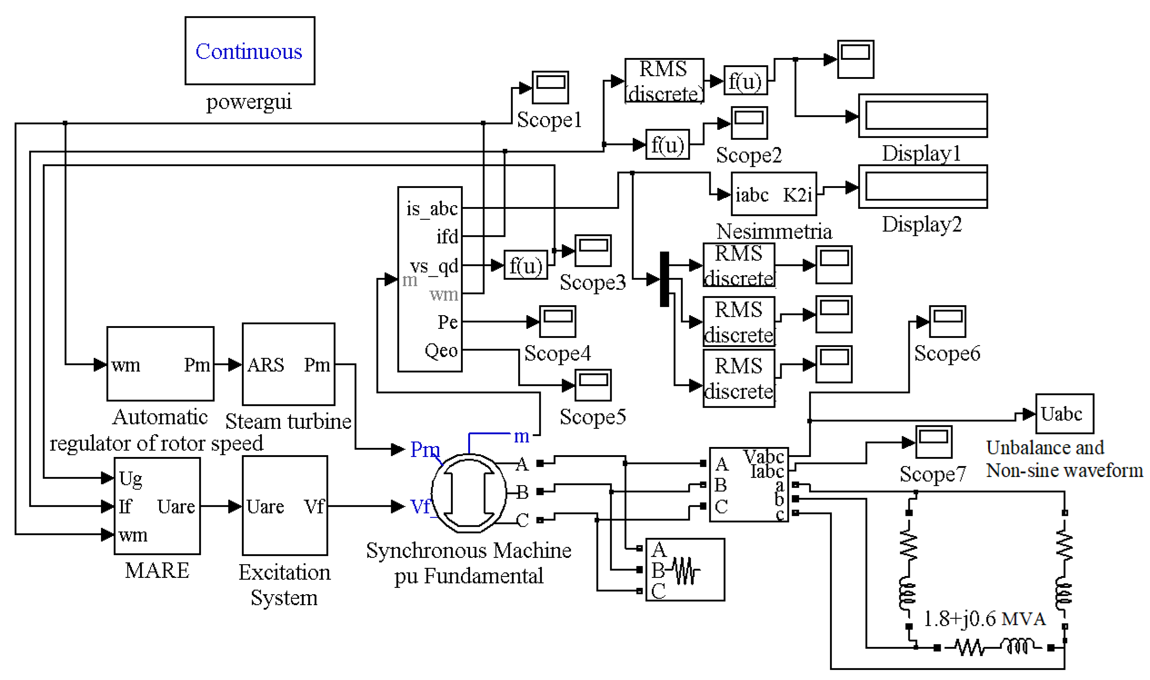
The flow chart of the investigated computer model, implemented using the Simulink and SimPowerSystems packages of the MATLAB R2022b environment, is shown in Figure 1. The “synchronous machine” block was used to simulate the generator of the DG unit, the parameters of which are shown in Table 1. A steam turbine (the “steam turbine” block in Figure 1) was used as the primary engine, the mathematical model of which with respect to the shaft power of the turbine and the regulator opening was characterized by the following transfer function:
where is the time constant of the turbine, determined by the lag in the conversion of steam energy into mechanical energy (on average, is 0.2 s), and s is a complex variable.
Figure 1.
Flow chart of the MATLAB model of the generator serving an unbalanced load.
Table 1.
Parameters of the synchronous machine SGS-14-1-100-6U.
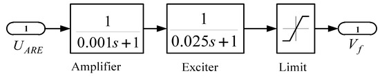
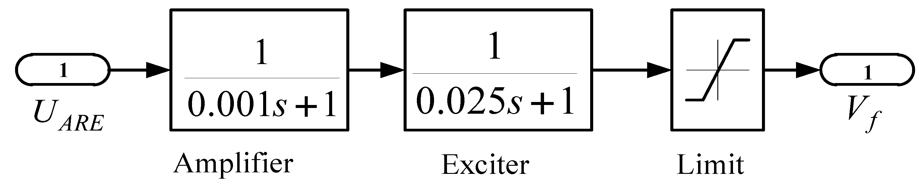
The excitation system model was formed based on the equations describing the thyristor converter and the input amplifier [25]. The exciter of the synchronous generator was modeled by the following transfer function, which is typical for a thyristor exciter [26]: . In this case, the model of the excitation system (the “excitation system” block in Figure 1) additionally takes into account the amplifier and the limiting block. The block diagram of the excitation system model is shown in Figure 2.
Figure 2.
Block diagram of the thyristor excitation system model in MATLAB: UARE—signal coming from ARE; Vf—signal coming to generator field winding; limit—voltage limitation block.
To regulate the generator voltage and rotor speed, we used the microprocessor-driven ARE and ARS models (the “MARE” and “automatic regulator of rotor speed” blocks in Figure 1), detailed in [26]. The voltage regulators were set up using the technique described in [27]. The measurements of non-sine waveforms and unbalance were performed using standard MATLAB SymPowerSystems blocks: total harmonic distortion and three-phase sequence analyzer.
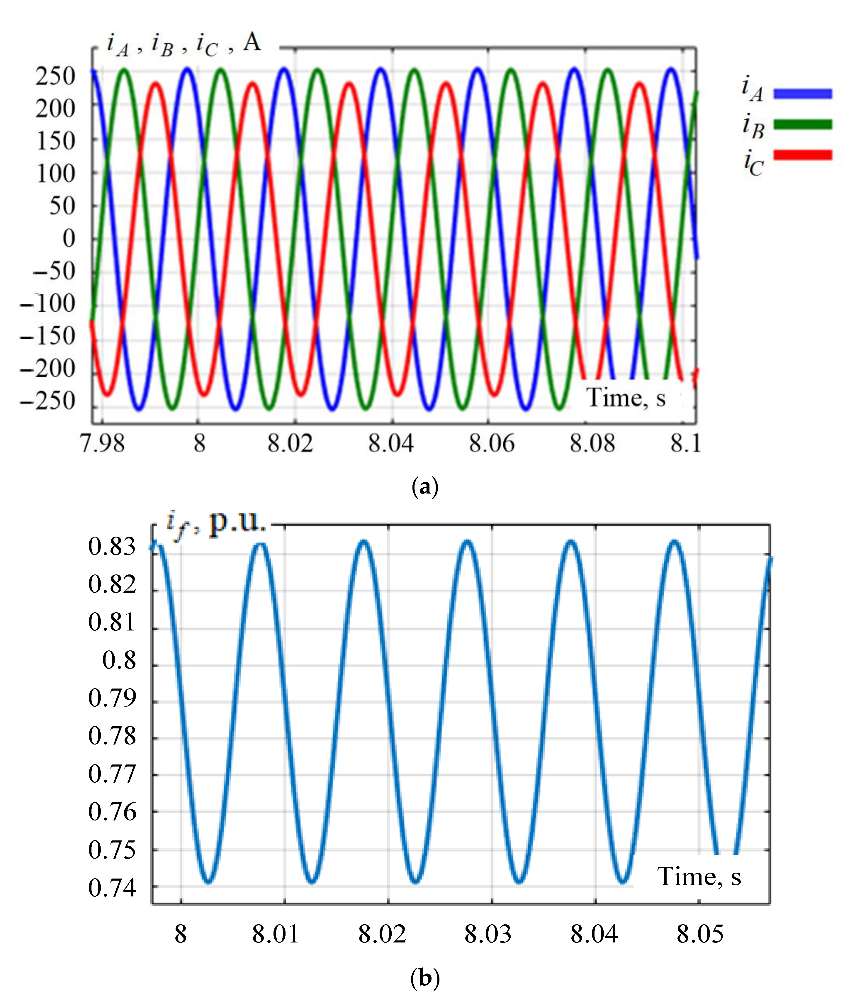
The generator in the model served an active and inductive load of 1.8 + j0.6 MV-A. The unbalanced currents and voltages were introduced by increasing the load between phases a and b. The load between phases b, c and c, a was reduced by an appropriate amount to maintain total power. The results of computer-aided simulations are summarized in Table 2 and illustrated in Figure 3 and Figure 4.
Table 2.
Experimental data for the case of the generator model in MATLAB serving a unbalanced load.
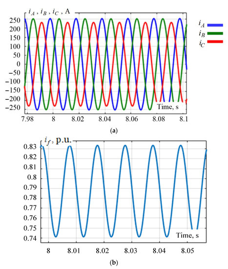
Figure 3.
Waveforms of stator currents (a) and rotor currents (b) of the generator at = 11.96%.
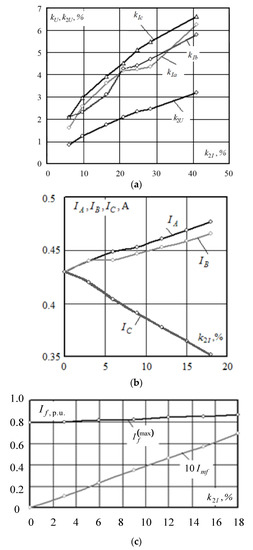
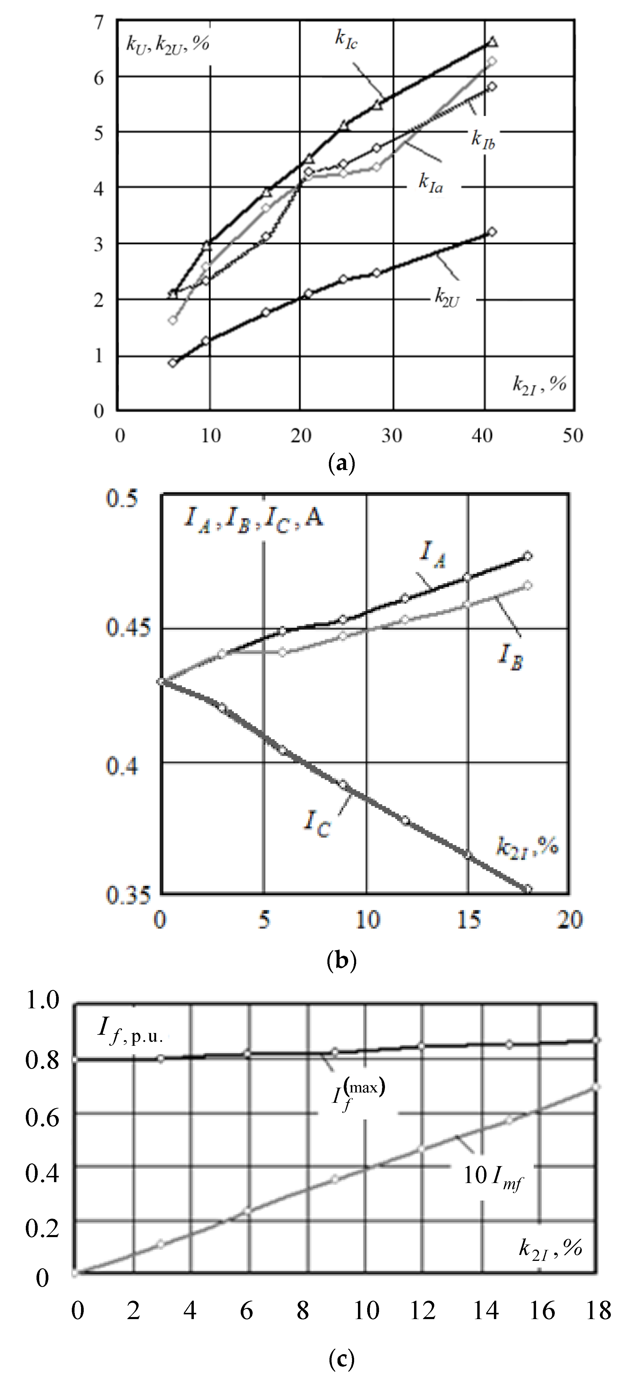
Figure 4.
Generator load flow as a function of the current unbalance ratio . ((a)— = f (), = f (); (b)—I = f (); (c)—If = f ()).
The average excitation current of the generator serving unbalanced loads was practically unchanged. However, as a result of the unbalance, currents with a frequency of 100 Hz were induced in the field winding, and the amplitude of forced current oscillations in the field winding increased linearly (Figure 4c). This is due to the fact that the unbalanced currents of the three-phase stator winding create an elliptical field, which is equivalent to the sum of two fields rotating at the same speed in opposite directions. The field component corresponding to the negative sequence currents rotates relative to the rotor at double synchronous speed and induces double frequency currents in the rotor circuits, which leads to additional losses.
The growth of the current unbalance ratio was accompanied by an increase in currents in individual phases and the level of voltage unbalance at the terminals of the synchronous generator, as well as the appearance of harmonic distortions. These circumstances must be taken into account when integrating DG units into RPSSs. Failure to take these factors into account can lead to rapid wear and tear of electrical equipment and even to breaking down of generators.
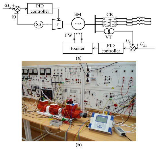
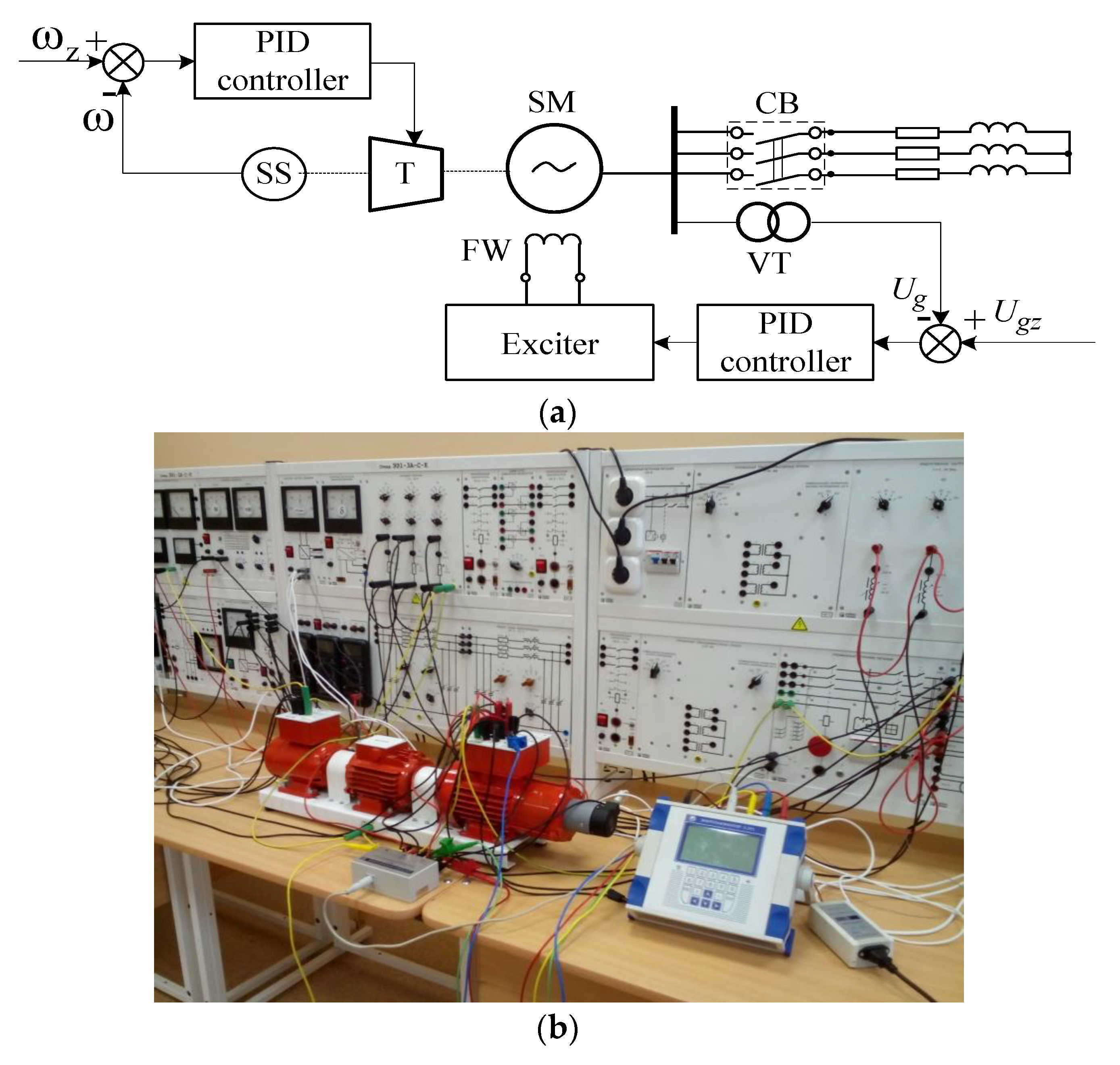
Studies were also carried out on a physical model of a low-power turbogenerator. A schematic and photo of the experimental setup are shown in Figure 5. The turbogenerator model was realized as coupled electric machines. The main nominal parameters of the electric machines of the physical model were as follows (Figure 2):
Figure 5.
Schematic (a) and photo (b) of the experimental setup: SS—RPM sensor; T—turbine; SM—synchronous machine; FW—field winding; VT—voltage transformer; CB—circuit breaker.
- Synchronous machine:
- -
- Active power P = 100 W;
- -
- Power factor cosφ = 1;
- -
- Stator winding voltage U = 220 V;
- -
- Nominal rotor speed n = 1500 rpm.
- Turbine modeled as a direct current machine:
- -
- Power P = 90 W;
- -
- Armature voltage Ua = 220 V;
- -
- Field winding voltage Uf = 220 V;
- -
- Rotation speed n = 1500 rpm.
To increase the inertia on one shaft of the synchronous generator and the DC machine, we installed a flywheel with a moment of inertia of 0.009 N⋅m⋅s2.
The generator in the simulation served resistive and inductive loads. The unbalance was created by increasing the load in phase A; the loads in the other phases were reduced by an appropriate amount to maintain full loading.
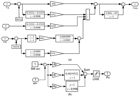
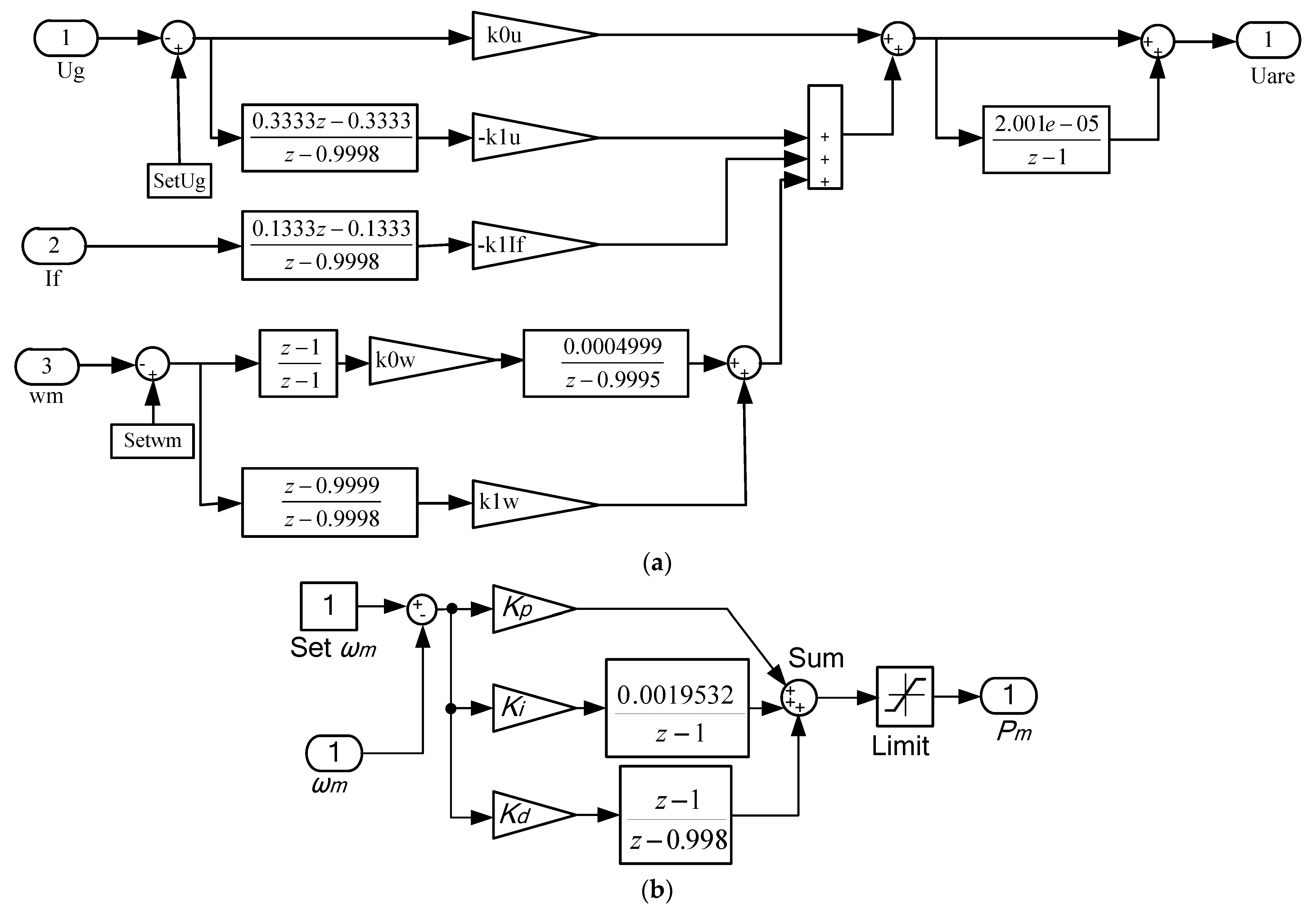
Regulation of generator speed and voltage was carried out on the basis of digital PID controllers, the block diagrams of which are shown in Figure 6.
Figure 6.
Flow charts of Simulink models of the ARE (a) and ARS (b) of the experimental setup.
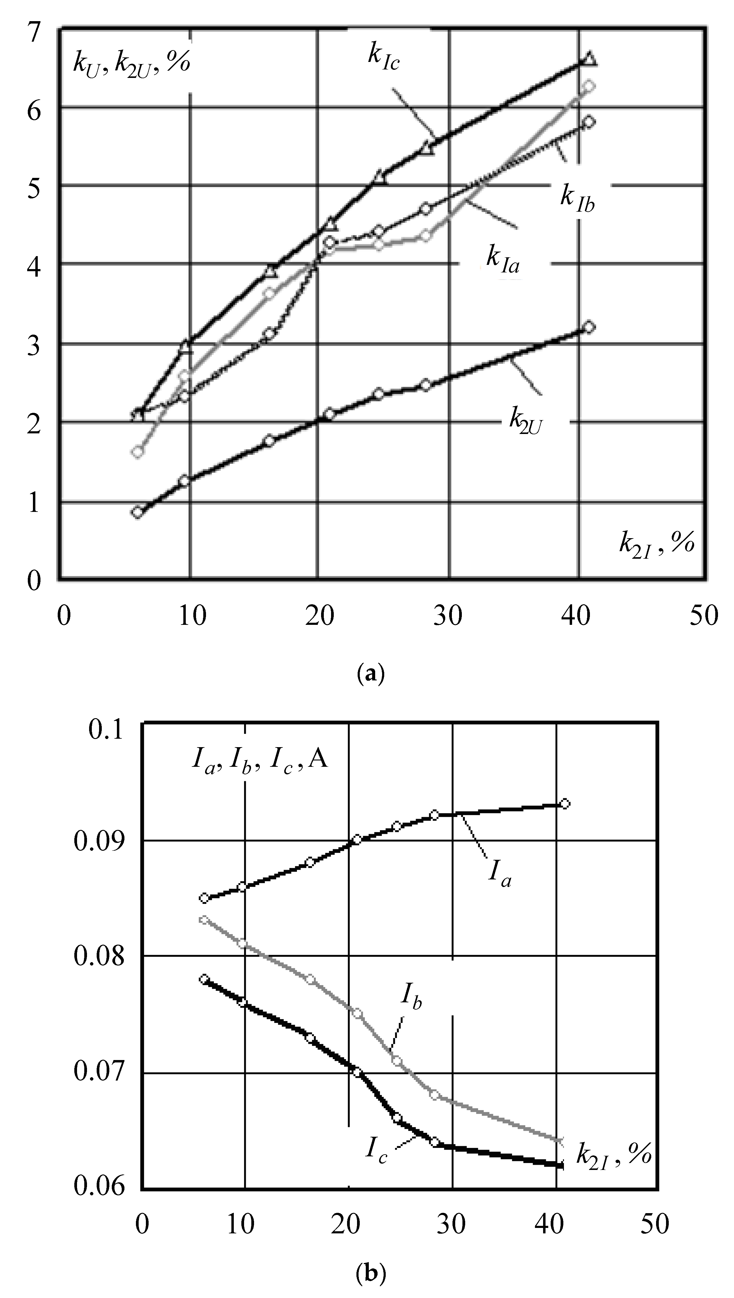
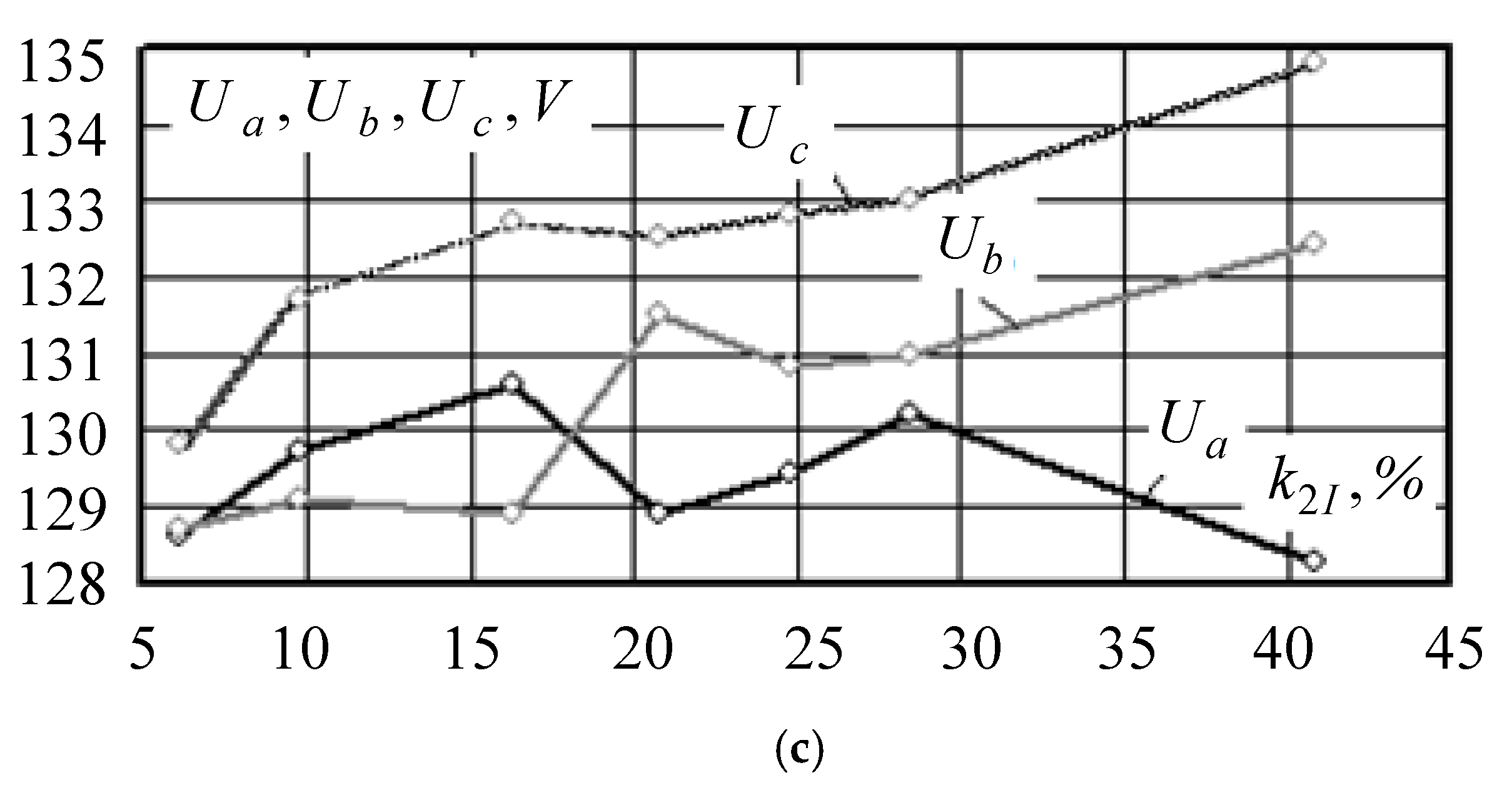
Experimental data obtained with the physical model of the turbogenerator, presented in Table 3 and Table 4 and Figure 7, confirmed the results of the computer-aided simulation detailed above. As a result of these studies, we found that when the generator served an unbalanced load, the stator winding had higher current and voltage harmonics, and the third harmonic had the greatest amplitude. This is explained by the fact that in the presence of an unbalanced load, a current of double frequency (100 Hz) is induced in the rotor winding, which in turn excites the magnetic field of the rotor, which rotates in the forward direction at a double frequency with respect to the rotor. This field is superimposed on the fundamental frequency magnetic field, which leads to the formation of a magnetic field of the rotor rotating in the forward direction at three times the frequency of the stator. Thus, the generated field will induce a current of triple frequency (150 Hz) in the stator winding.
Table 3.
Parameters of the physical model of the turbogenerator serving an unbalanced load.
Table 4.
Harmonic distortion of generator current and voltage under an unbalanced load.
Figure 7.
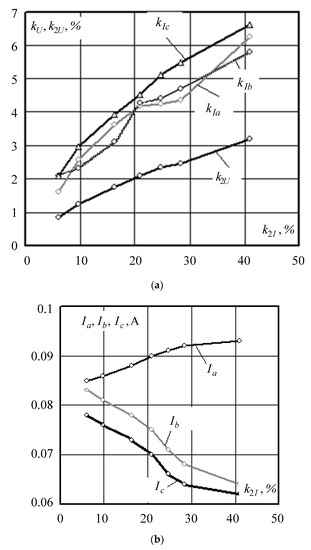
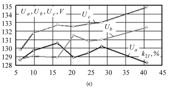
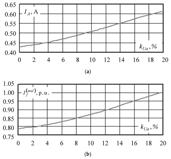
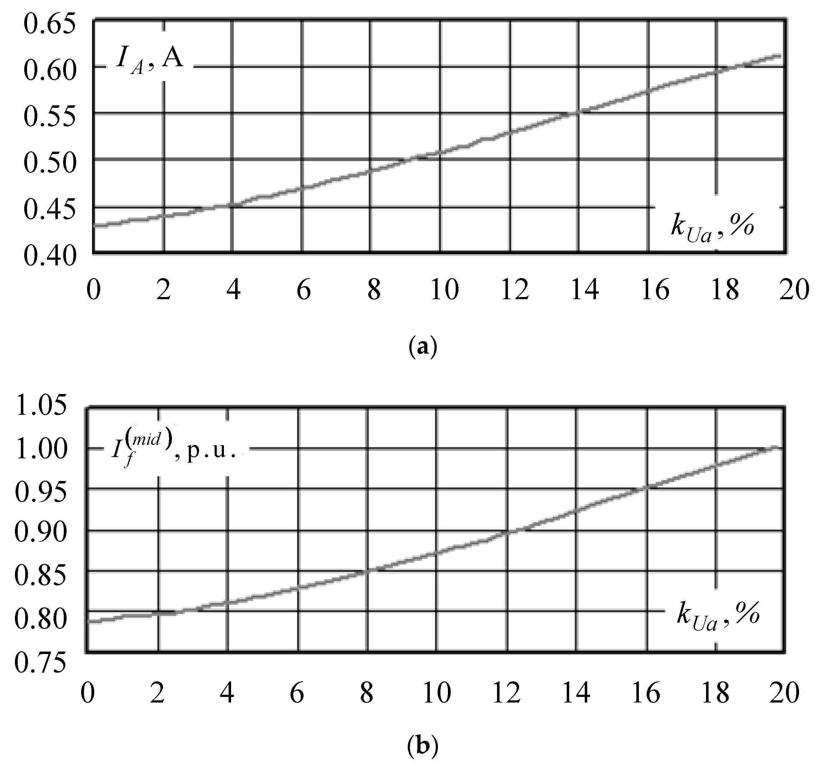
Generator load flow as a function of the current unbalance ratio . ((a)— = f (), = f (); (b)—I = f (); (c)—U = f ()).
Due to the fact that the generator was loaded at about one third of its rated power, the maximum phase current difference slightly exceeded the allowable 12% only at the value of equal to 40%. It should also be noted that the effective value of the excitation current of the generator serving an unbalanced load remained practically unchanged. The relationships shown in Figure 7 differ slightly from the nearly linear ones obtained by computer-aided simulation. The differences are due to a number of assumptions made in the simulation, as well as measurement errors. This is especially true for current measurements in the presence of harmonic distortions.
The results of computer-aided and physical modeling revealed the following:
- When the synchronous generator served an unbalanced load, there was a noticeable negative sequence current, which may exceed the maximum allowable value with respect to overheating. The generator began to emit higher harmonics into the network, which led to extra heating. In the experiments carried out on computer and physical models, the difference between the currents of the stator phases slightly exceeded the maximum permissible value and amounted to 12.5% for the computer model and 12.9% for the physical one.
- The average excitation current of a generator serving an unbalanced load was practically unchanged, but there was a 100 Hz current in the field winding whose amplitude increased linearly as the load unbalance increased. Therefore, the excitation current and the generator load should be limited.
- The power limitation of a generator serving unbalanced loads can be determined by the difference in phase currents, which must not exceed 12% of the nominal current.
3. Non-Linear Load Effect on Operation of Low-Power Synchronous Generator
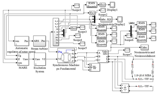
A flow chart of the computer model that was used in the study is shown in Figure 8. The turbogenerator in the model served a resistive and inductive load of 1.8 + j0.6 MWA. Distortion of the current and voltage sine waveform was carried out by consistently increasing the rectifier power with a simultaneous reduction of the main load of the turbogenerator so that the total load remained unchanged. The results of computer-aided simulation are summarized in Table 5 and illustrated in Figure 9 and Figure 10.
Figure 8.
Flow chart of the model of the turbogenerator serving balanced and non-linear loads in MATLAB.
Table 5.
Experimental data for the MATLAB model of the turbogenerator serving a non-sine waveform load.
Figure 9.
Stator current (a) and rotor current (b) of the generator as a function of the deviation of the voltage waveform from the sine waveform.
Figure 10.
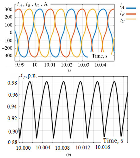
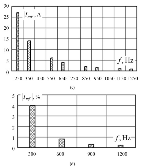
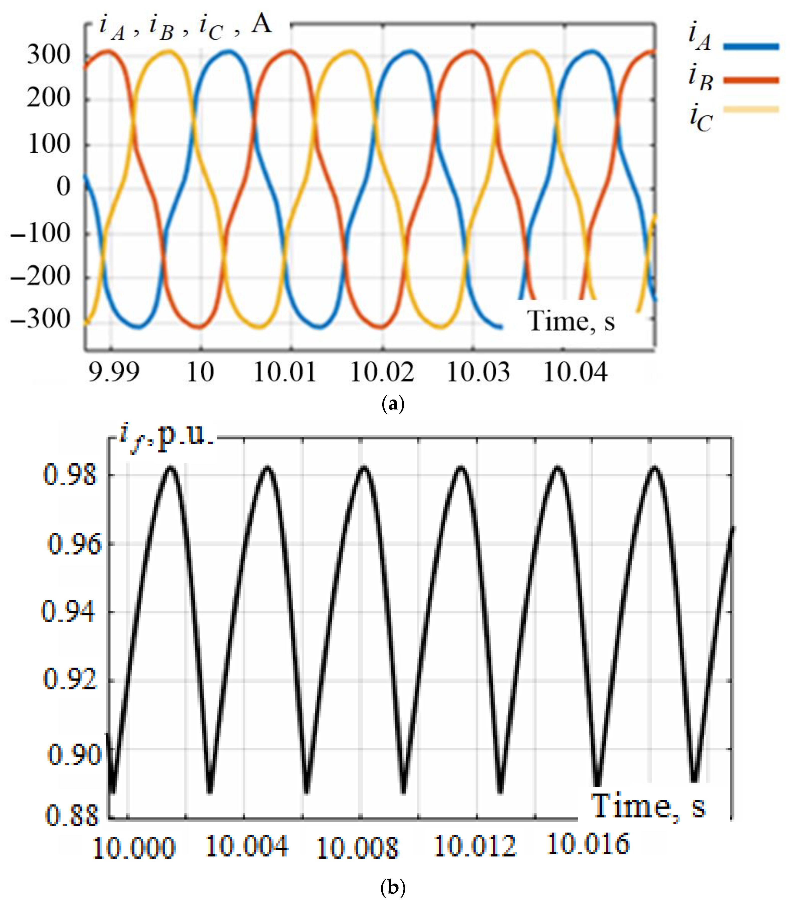
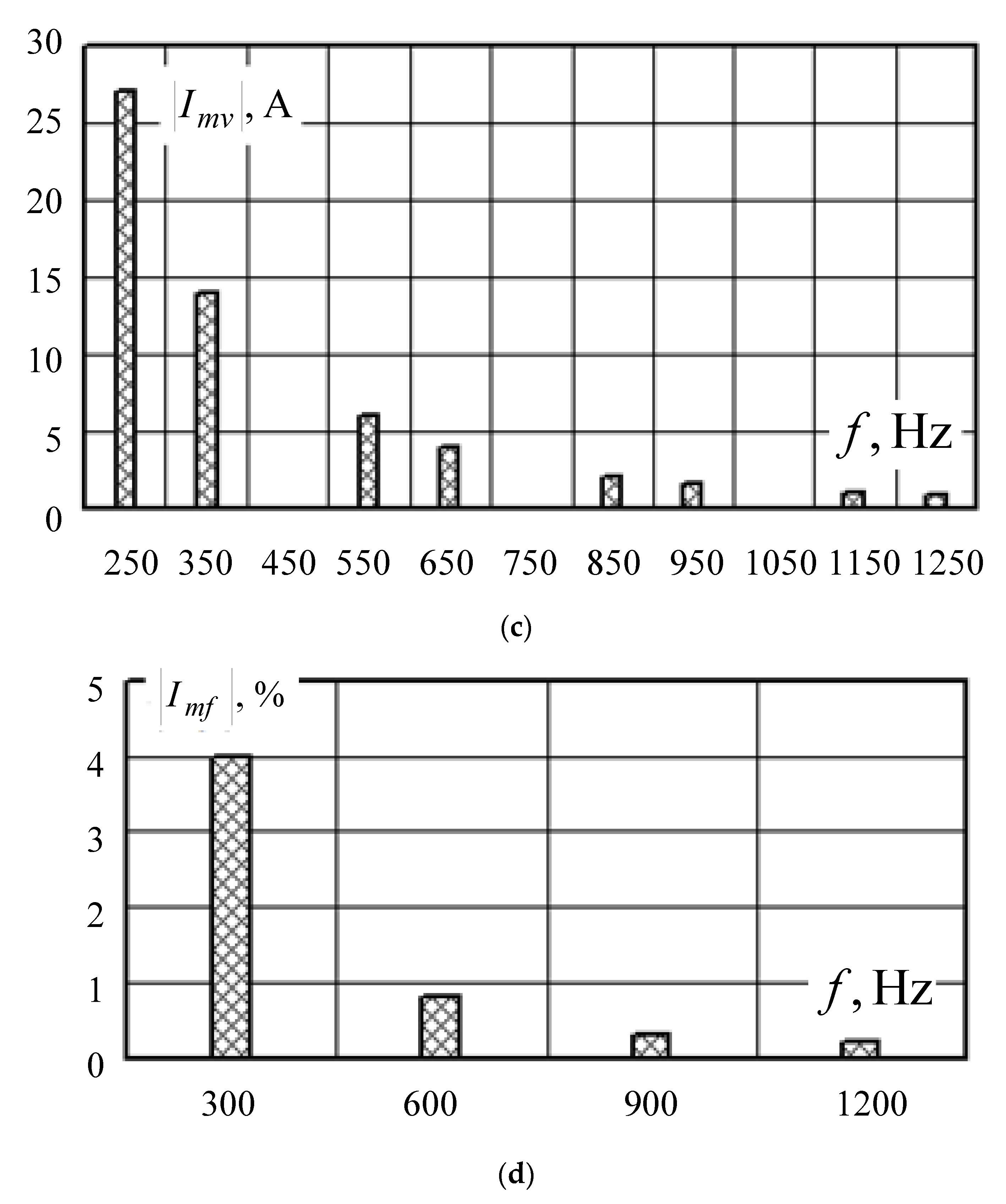
Waveforms of stator currents (a) and rotor currents (b) of the generator and their harmonic content (c,d) at = 15.6%.
An increase in harmonic components of load current led to an increase in stator and rotor currents of the turbogenerator (Figure 9) while maintaining the balanced load flow.
The results of the study also showed that when the voltage and current waveforms deviated more from the sine waveform, the amplitude of the forced oscillations of the excitation current of the generator at a frequency multiple of 300 Hz increased, which led to additional losses and extra heating (Figure 10c,d). This circumstance is due to the fact that the higher harmonics in the turbogenerator stator current curve create magnetic fields rotating in the forward and reverse directions with the harmonic frequency. These fields, rotating asynchronously with respect to the rotor, are superimposed on the magnetic field of the fundamental frequency and induce high-frequency currents in the rotor circuits. If there are odd harmonic currents in the stator winding, even harmonic currents are induced in the rotor winding as a result of the interaction of magnetic fields.
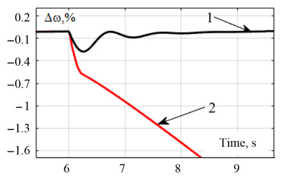
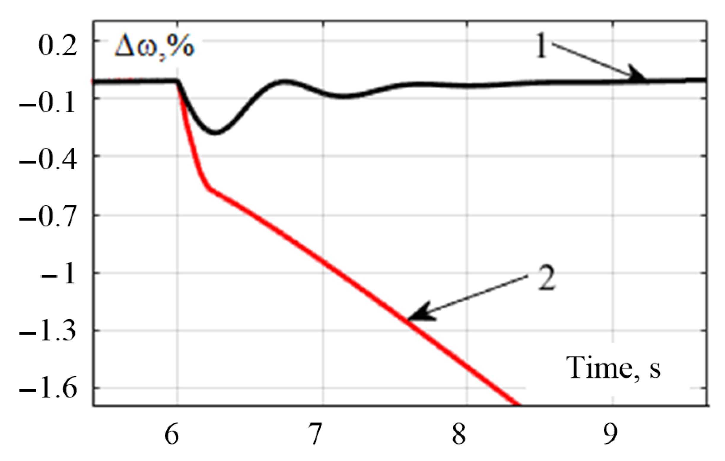
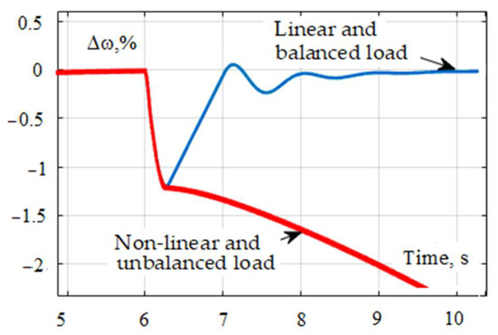
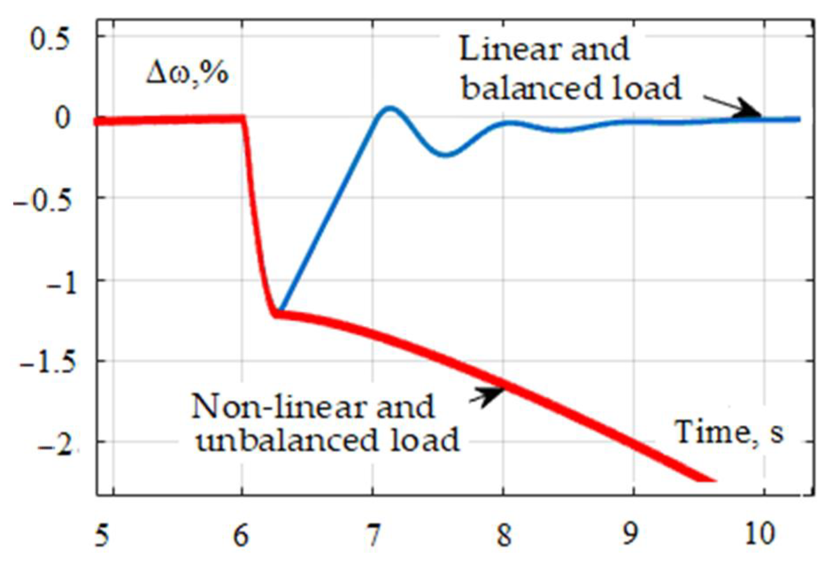
Thus, an increase in the harmonic distortion of the load current was accompanied by a growth of stator and rotor currents and the occurrence of forced oscillations of electrical and mechanical parameters of the generator. This should be considered when introducing DG units into RPSSs. Failure to consider these factors can lead to rapid wear and tear of equipment and even breakdown of generators. In addition, given significant deviation from the sine waveform, the stability margin was reduced, and the probability of the generator switching into asynchronous operation increased. Experiments run on the simulation model showed that when the generator served a rectifier load, the power of which was 85% of the rated generator power, and an additional load was connected, the system lost stability, and the generator started asynchronous operation. When serving linear loads of the same power, ARE and ARS effectively dampened the disturbances introduced into the system. The waveforms of the rotor speed of the turbogenerator that illustrate these conclusions are shown in Figure 11: the load was 85% of the rated power of the turbogenerator. In this experiment, the sine-wave distortion coefficient of the voltage waveform reached , while the RMS value of the excitation current increased by 55% compared with the operation that served a linear load. These circumstances, which also take place in real-world operation of RPSSs, must be taken into account as well when deciding on the settings of the ARE and ASR of generators of DG units.
Figure 11.
Waveforms of the turbogenerator rotor speed deviation when additional load was connected: 1—linear load; 2—non-linear load.
Thus, the loss of stable operation of the synchronous generator is due to the incorrect operation of the regulators and an additional increase in the stator and rotor currents, which reduces the actual stability margin.
On the basis of computer-aided simulation it was found that the following effects took place when the harmonic distortion of the load current increased:
- The stator and rotor currents of the generator were significantly increased. For example, at %, the RMS value of the stator current increased by 32% compared with the load flow when there was no rectifier load. At %, the average excitation current increased by 2.5% compared with the load flow when there was no rectifier load, and at % (rectifier load was 25% of the generator rated power), the average excitation current increased by 20%. This fact is due to improper operation of the ARE under such conditions, which requires the use of harmonic filters and excitation current limitation in the ARE.
- The amplitude of the forced oscillations of the generator excitation current at a frequency multiple of 300 Hz increased. For example, at %, the amplitude of the forced oscillations was 5% of the effective signal. This led to additional losses and extra heating.
- There were additional mechanical vibrations of the rotor with a frequency of 300 Hz. As the deviation from the sine waveform increased, the amplitude of these oscillations increased as well, which can lead to excessive runout during operation, rapid wear of the generator, and loss of stability.
4. Joint Effect of Unbalanced and Non-Linear Loads on Operation of a Low-Power Synchronous Generator
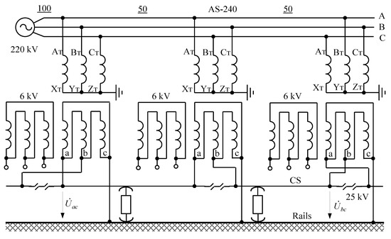
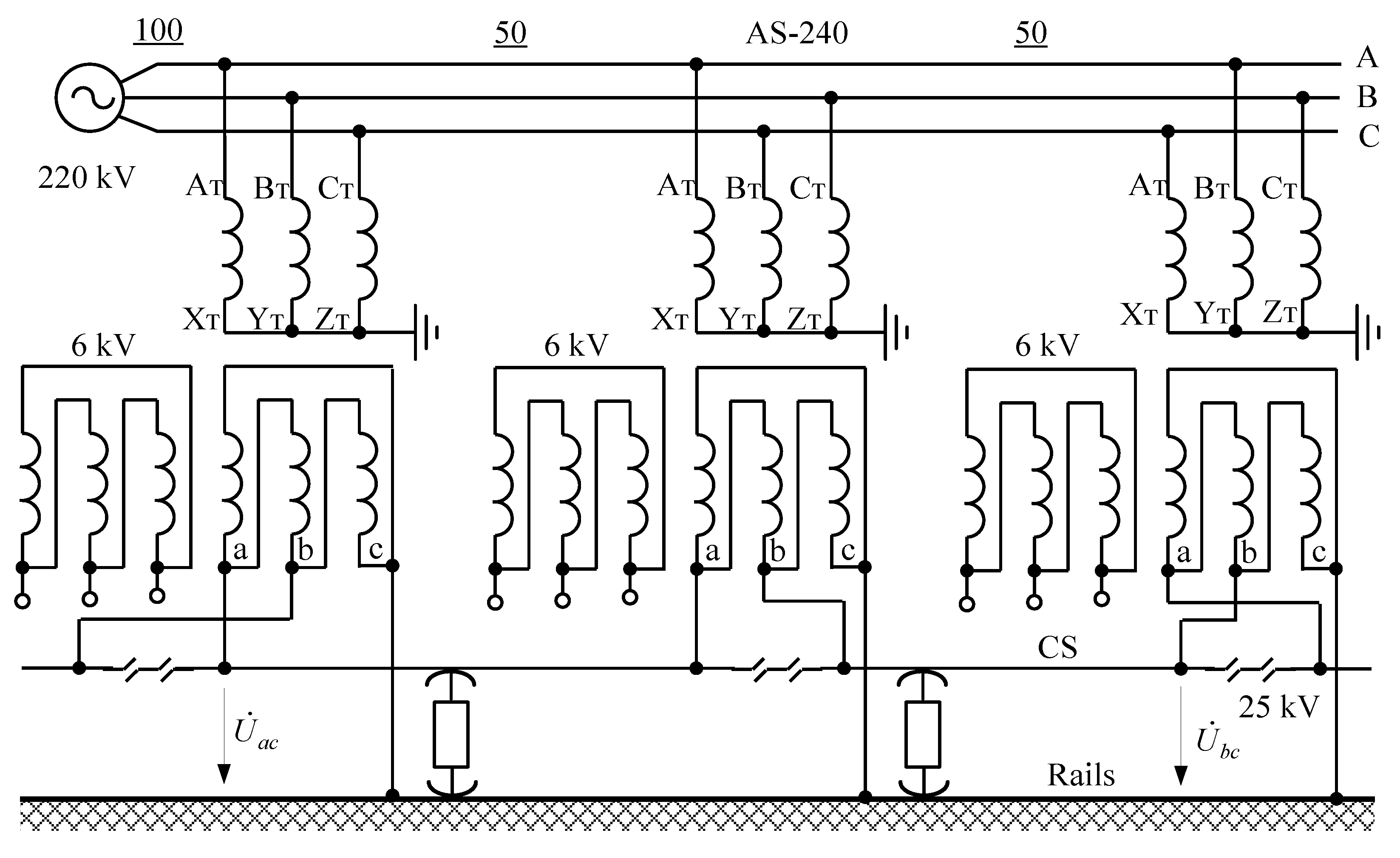
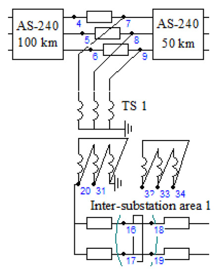
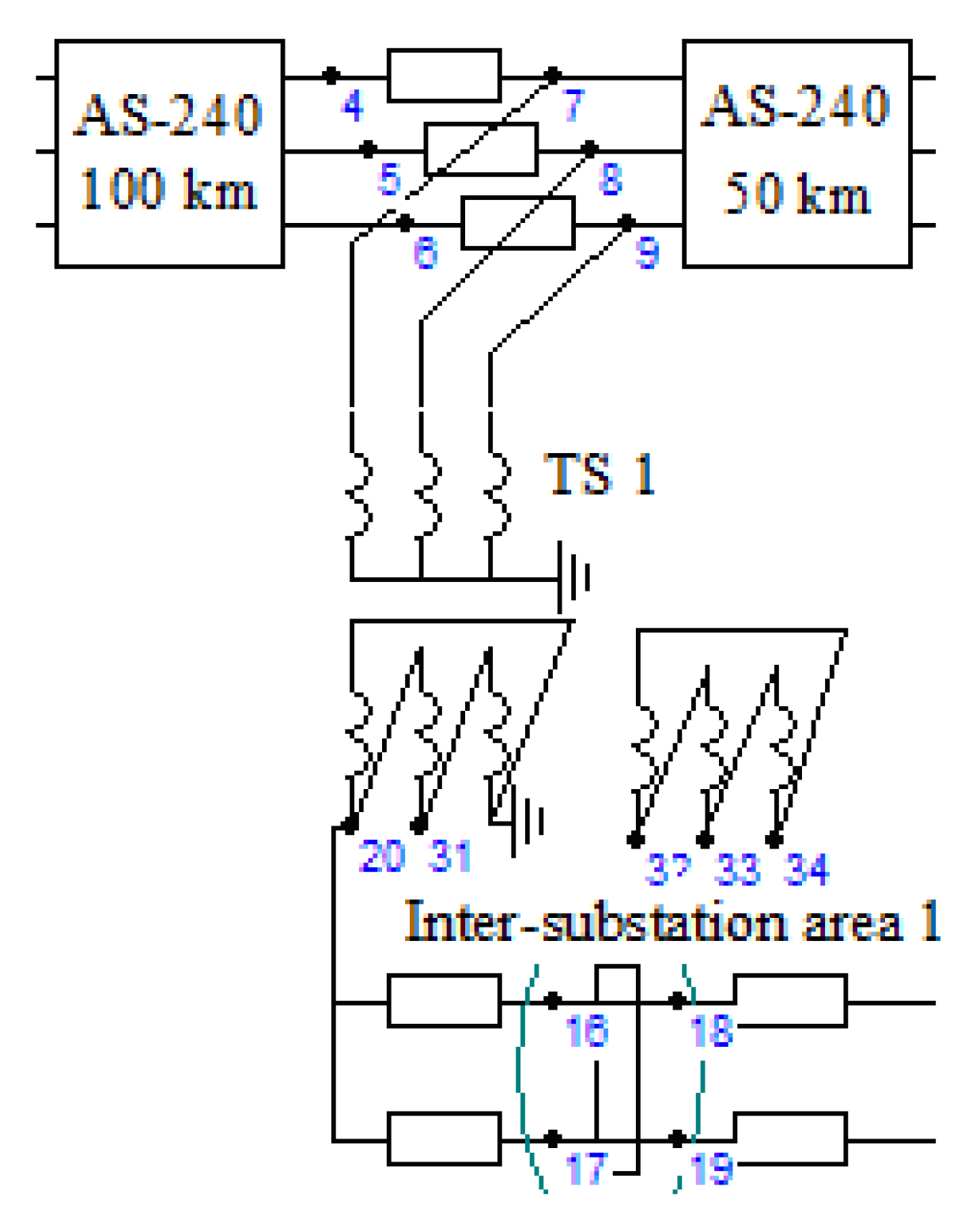
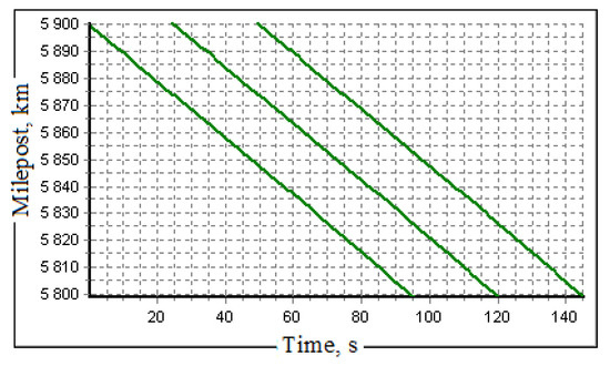
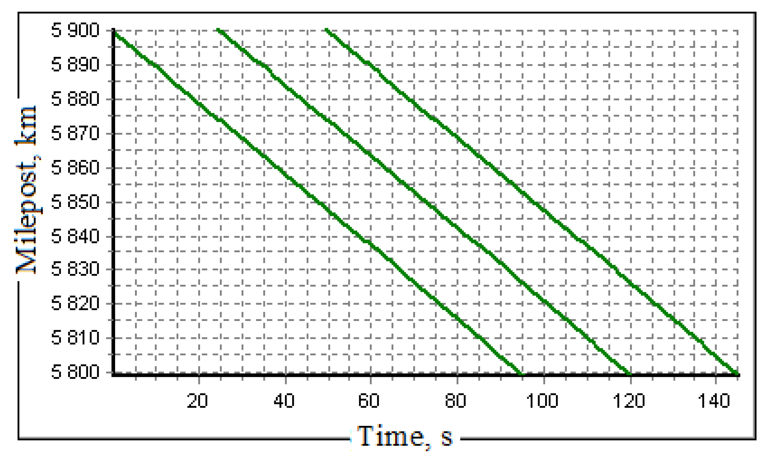
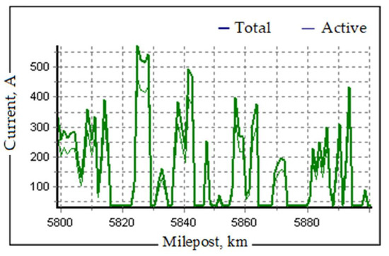
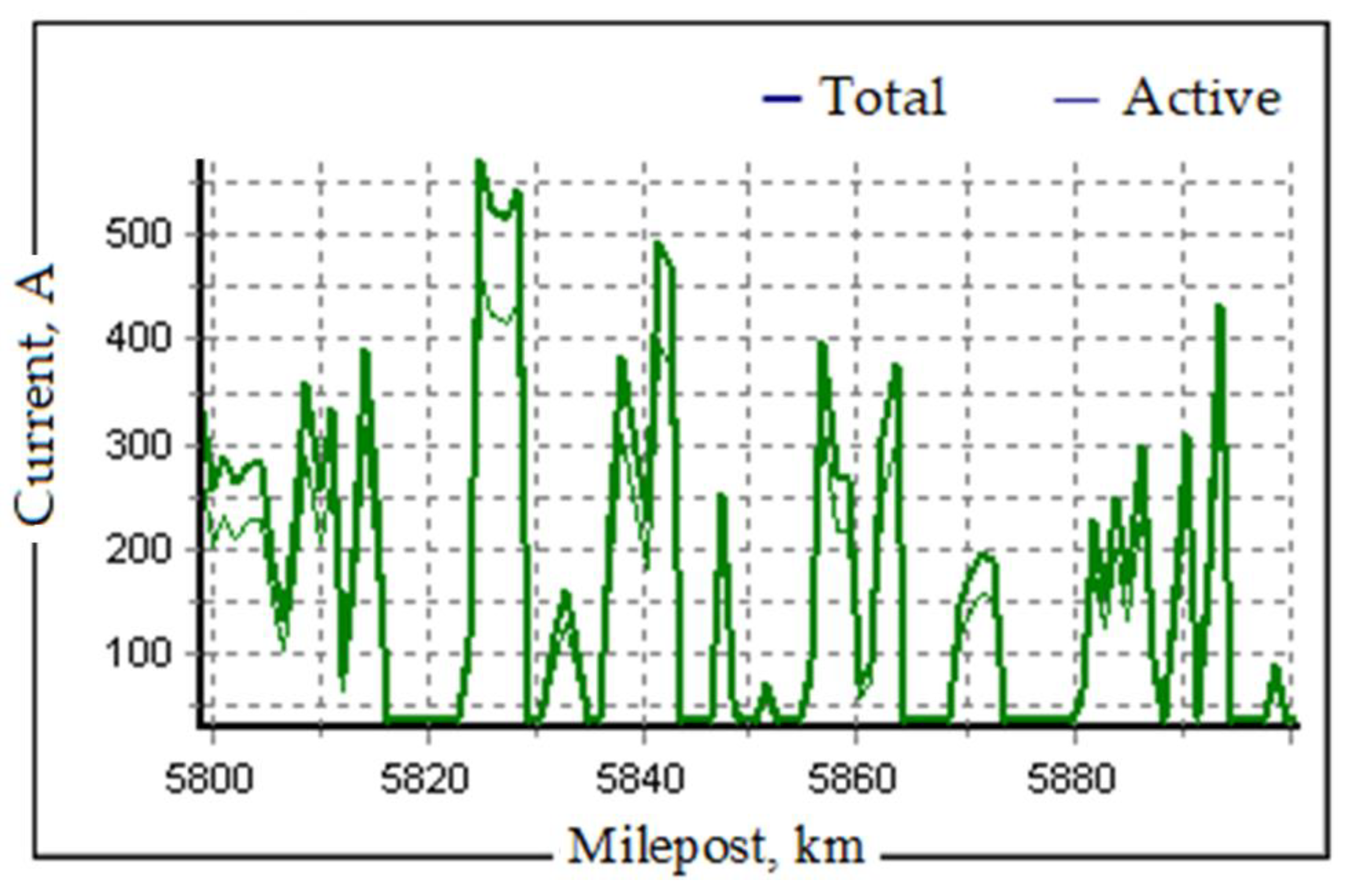
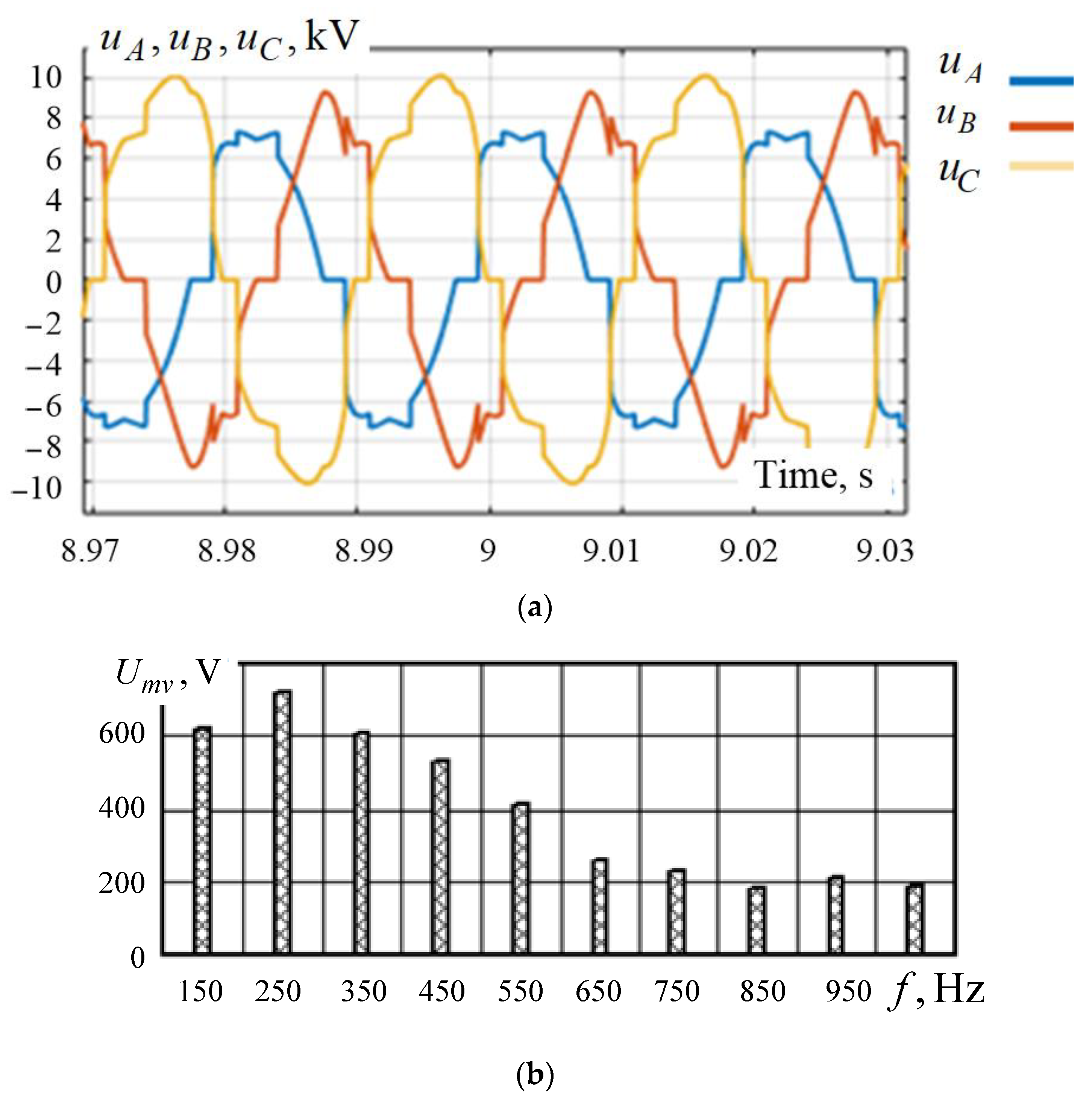
To assess the levels of unbalance and harmonic distortion in 6, 10, and 35 kV networks, fed from traction substations (TS), we modeled a section of a standard power RPSS, the circuit of which is shown in Figure 12. The modeling was carried out based on the Fazonord software package developed at Irkutsk State Transport University [23]. A flow chart of the computational model is shown in Figure 13. We studied three freight trains weighing 5000 tons moving in the odd direction. The train schedule is shown in Figure 14, and the current profile of the train is shown in Figure 15.
Figure 12.
Diagram of a section of a standard 27.5 kV RPSS.
Figure 13.
Detail of the computational model circuit.
Figure 14.
Train schedule.
Figure 15.
Current profile of a train weighing 5000 tons.
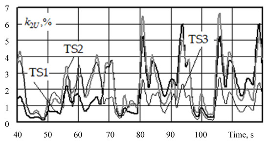
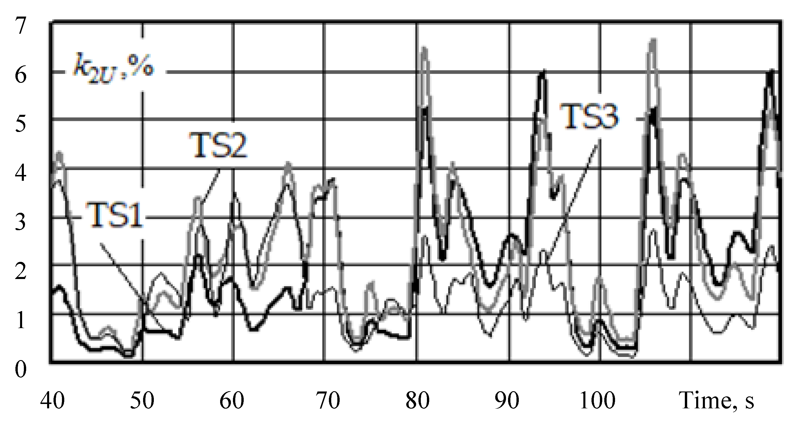
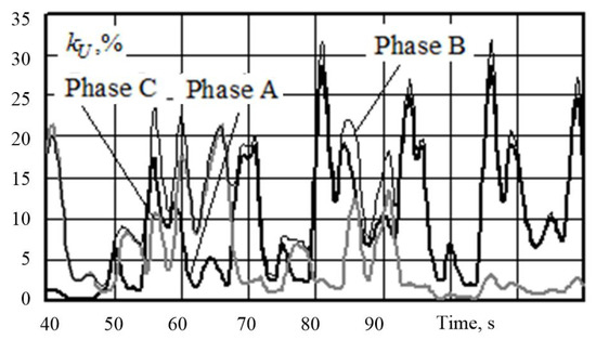
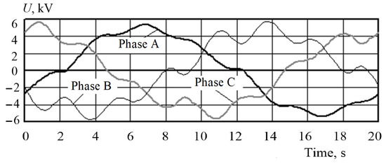
The simulation results are presented in Table 6 and Table 7 and illustrated in Figure 16, Figure 17 and Figure 18.
Table 6.
The results of calculation of unbalance parameters at 6 kV busbars of the TS.
Table 7.
Results of calculating total harmonic distortions at 6 kV buses of TS2.
Figure 16.
Negative sequence unbalance ratios at 6 kV busbars of the TS.
Figure 17.
Total harmonic distortion at 6 kV buses of TS2.
Figure 18.
Waveforms of phase voltages at 6 kV busbars of TS2.
The obtained results allow us to conclude that even a limited movement induced significant levels of unbalance, and harmonic distortions were observed at 6 kV buses of the simulated RPSS. The mean values of the total harmonic distortion were within 4.5...10%, and the maximum value of the unbalance ratio in the negative sequence reached 3.7...6.5%. Thus, the relevance of the problems related to the study of load flows of low-power generators under increased unbalance and harmonic distortions was further confirmed.
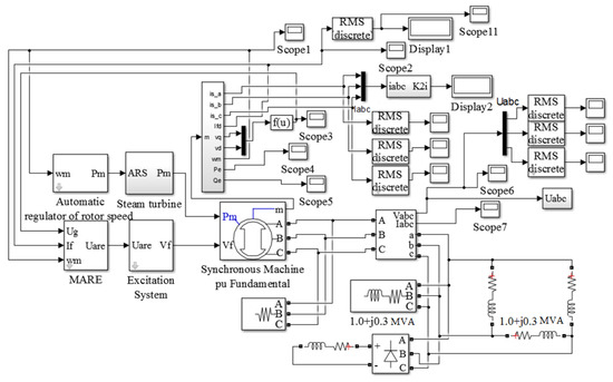
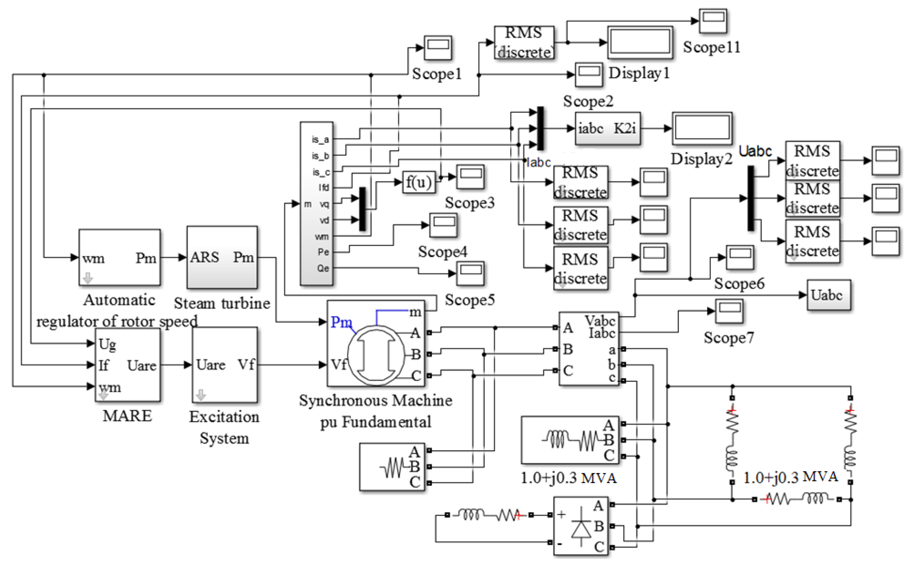
The flow chart of the investigated simulation model that was implemented using the MATLAB Simulink and SimPowerSystems packages is shown in Figure 19. The turbogenerator served an active and inductive load of 2 + j0.6 MWA. The rectifier load was consistently increased to increase the deviation from the sine waveform. At the same time the main balanced load was reduced so that the total load of the generator remained unchanged. The unbalanced currents and voltages were introduced by increasing the linear load between phases a and b. At the same time, the load between phases b, c and c, a was reduced to maintain the total power.
Figure 19.
Flow chart of a computer model of the turbogenerator serving an unbalanced and non-linear load.
The results of the computer-aided simulations shown in Figure 20, Figure 21, Figure 22 and Figure 23 attest to the following:
Figure 20.
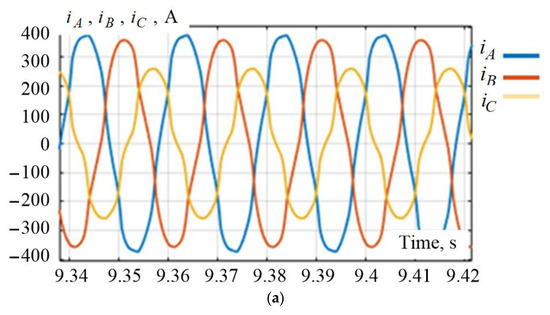
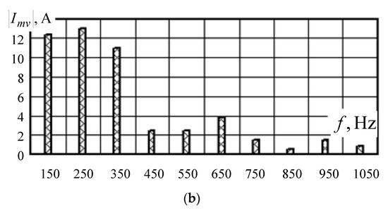
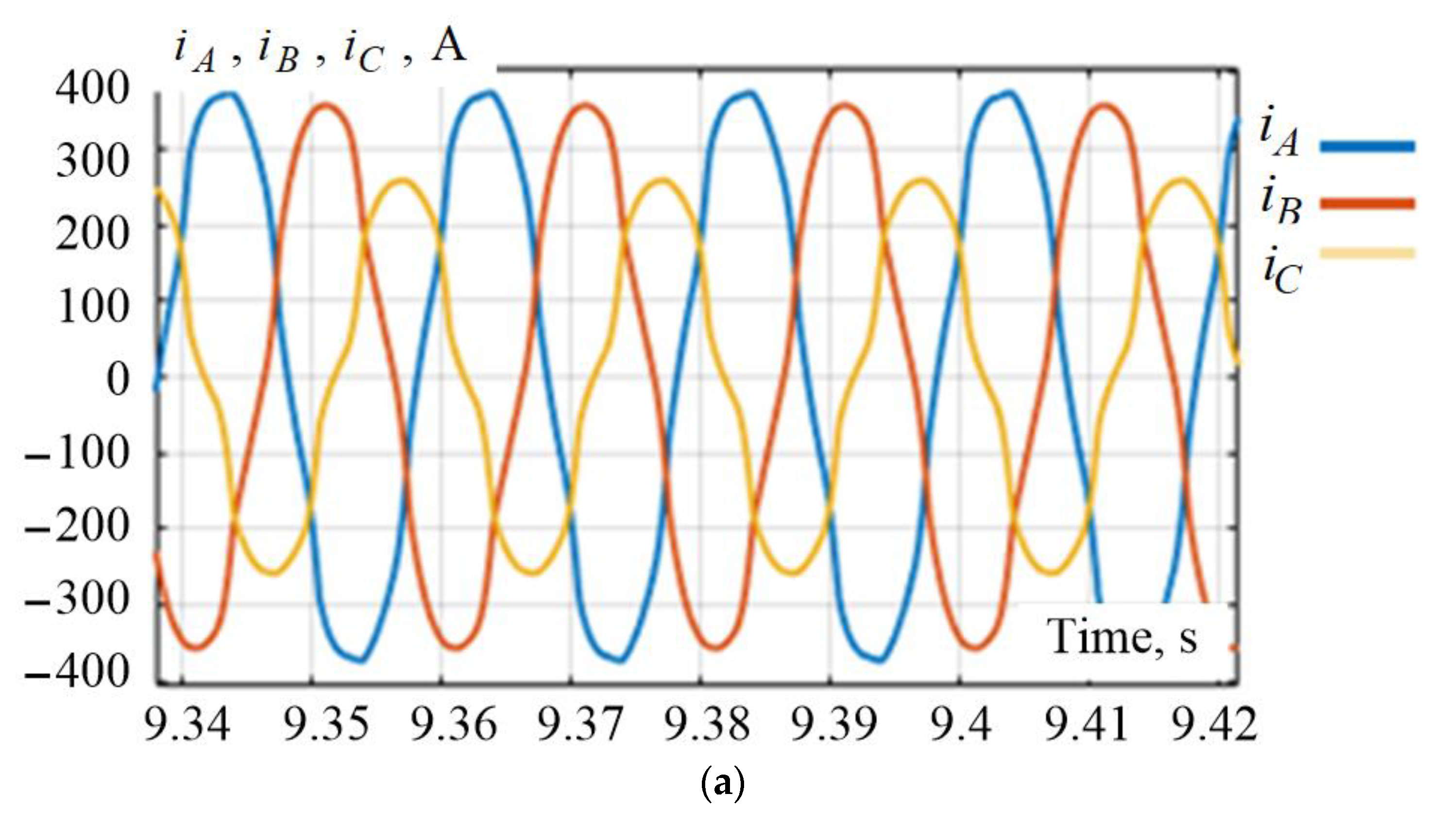
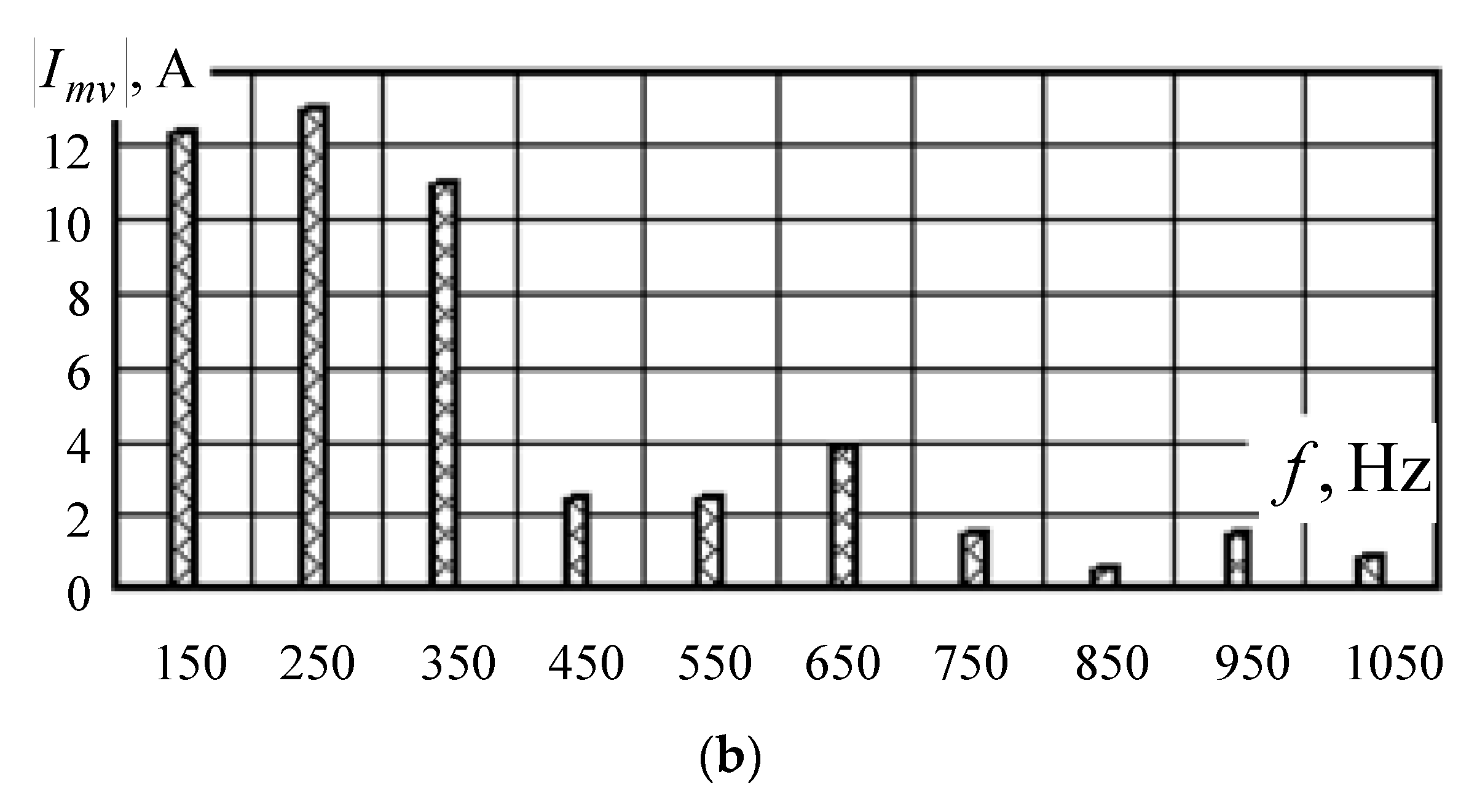
Waveforms of generator stator currents (a) and their harmonic content (b) at % and %.
Figure 21.
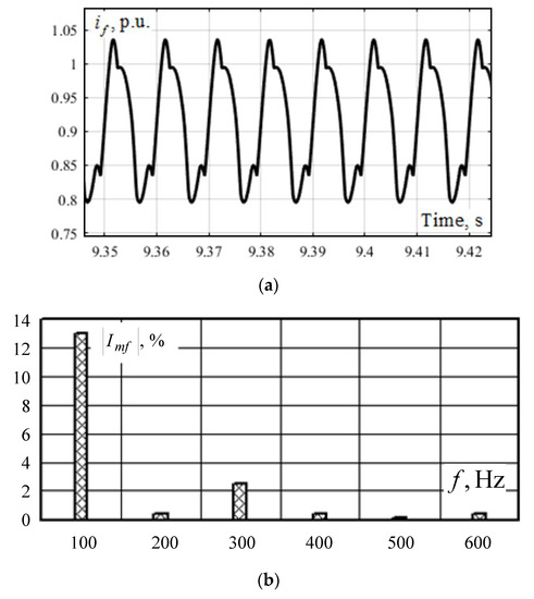
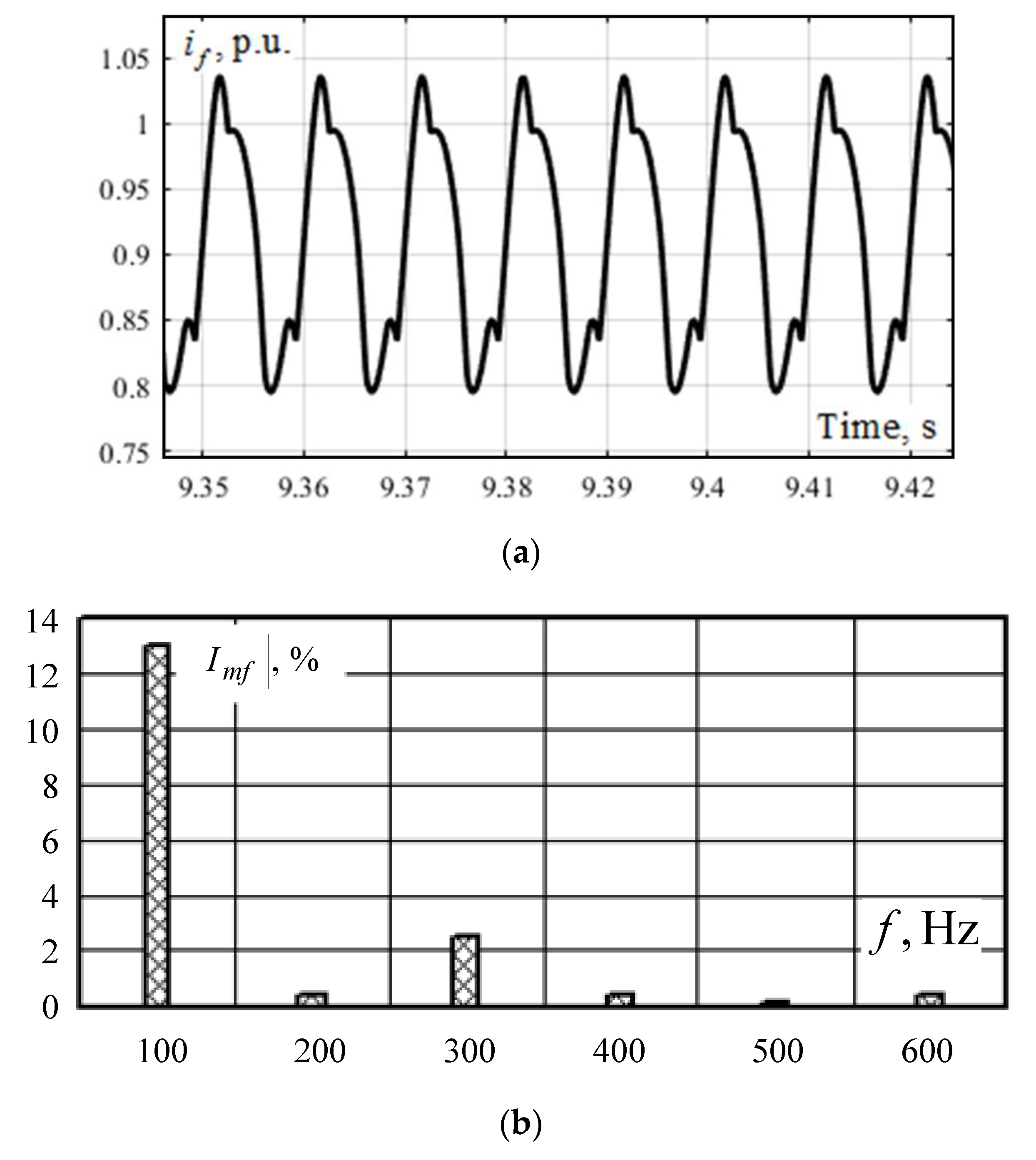
Waveform of the generator excitation current (a) and its harmonic content (b) given % and %.
Figure 22.
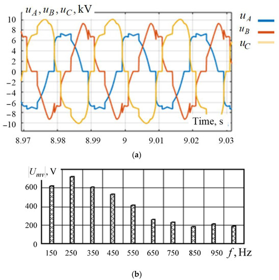
The waveform of generator stator voltages (a) and its harmonic content (b) when feeding a non-linear unbalanced load.
Figure 23.
Waveforms of generator rotor speed deviation when an additional load was connected.
- Due to the presence of an unbalanced load, there were harmonics of 150 Hz in the stator current (Figure 20) and 100 Hz in the rotor current, which caused an increase in the excitation current.
- The amplitude of the forced oscillations of the excitation current of the generator with a frequency of 300 Hz increased (Figure 21). These factors entail the use of harmonic filters and field current limiting automatics in the ARE.
- The currents increased in the individual phases (Figure 20), which led to extra heating.
It should also be noted that with increasing unbalance and deviation of current and voltage waveform from the sine waveform, the amplitude of the mechanical vibrations of the generator rotor at 100 and 300 Hz increased, which can cause excessive runout during operation and accelerated wear of the generator.
The increase in the difference of currents in the generator phases led to an increase in the coefficient , which was accompanied by an increase in the level of voltage unbalance at the generator terminals, as well as the appearance of harmonic distortions (Figure 22). These facts of RPSSs should be taken into account when introducing DG units since failure to do that can lead to the accelerated wear and tear of electrical equipment.
Results of our study also indicated that when the generator served unbalanced and non-linear loads with a total power of 2.4 + j1.45 MV-A (which corresponded to 90% turbogenerator load), the amplitude of the forced oscillations of the electrical and mechanical parameters reached the limiting values, which led to a significant increase in equipment wear, the improper operation of the microprocessor-driven ARE and ARS, and, consequently, a decrease in the stability margin. For example, when an additional load was connected, the system lost its stability (Figure 23).
Thus, when DG units serve non-linear and unbalanced loads, it is necessary to implement special measures to protect the generating equipment: the use of DC links [6], the use of harmonic filters, the installation of generator protections limiting negative sequence current, the use of automatic excitation current limitation, etc.
5. Conclusions
The results of the studies on the effect of unbalanced and non-linear loads on the load flows of a low-power synchronous generator allow us to draw the following conclusions:
- When the generator serves an unbalanced load, there is a noticeable negative sequence current, which may exceed the maximum allowable value with respect to overheating. The generator begins to emit higher harmonics into the network, which leads to extra heating.
The average excitation current of a generator serving an unbalanced load was practically unchanged, but there was a 100 Hz current in the field winding whose amplitude increased linearly with increasing load unbalance. Therefore, the excitation current and the generator load should be limited.
The power limitation of a generator serving unbalanced loads can be determined by the difference in phase currents, which must not exceed 12% of the nominal current.
- 2.
- The following effects occurred when the harmonic distortion of the load current increased:
- The generator stator and rotor currents increased significantly; for example, at %, the RMS value of stator current increased by 32% as compared with the load flow when there was no rectifier load; at %, the mean value of the excitation current increased by 2.5% as compared with the load flow when there was no rectifier load; and at % (rectifier load was 25% of the generator rated power), the mean value of the excitation current increased by 20%. This fact was due to the improper operation of the ARE under such conditions, which required the application of harmonic filters and excitation current limitation in the ARE.
- The amplitude of the forced oscillations of the excitation current of the generator at a frequency multiple of 300 Hz increased; for example, at %, the amplitude of forced oscillations was 5% of the effective signal. This led to additional losses and extra heating.
- There were additional mechanical vibrations of the rotor with a frequency of 300 Hz; as the deviation from the sine waveform increased, the amplitude of these vibrations increased as well, which can lead to excessive runout during operation, rapid wear of the generator, and loss of stability.
- 3.
- Applicable to the case where there was a joint effect of unbalance and harmonic distortion, the following conclusions can be stated:
- There was a noticeable negative sequence current, which may exceed the maximum allowable value with respect to overheating; the generator began to emit higher harmonics into the network, which led to additional losses and a decrease in the power factor.
- The amplitude of the forced oscillations of the excitation current of the generator with frequency multiples of 100 and 300 Hz increased, which also led to additional losses and extra heating.
- Additional mechanical vibrations of the generator rotor occurred, which can lead to excessive runout during operation, accelerated wear of the generator, and loss of stability.
Author Contributions
Conceptualization, Y.B. and A.K.; methodology, Y.B., A.K. and K.S.; software, Y.B.; validation, Y.B., A.K. and K.S.; formal analysis, A.K. and K.S.; investigation, Y.B., A.K. and K.S.; resources, K.S.; data curation, Y.B.; writing—original draft preparation, Y.B., A.K. and K.S.; writing—review and editing, Y.B. and K.S.; visualization, K.S.; supervision, K.S.; project administration, A.K. and K.S.; funding acquisition, K.S. All authors have read and agreed to the published version of the manuscript.
Funding
The research was carried out within the framework of state task “Conducting applied scientific research” on the topic “Development of methods, algorithms and software for modeling the modes of traction power supply systems for DC railways and electromagnetic fields at traction substations for AC railways”.
Institutional Review Board Statement
Not applicable.
Informed Consent Statement
Not applicable.
Data Availability Statement
Data sharing not applicable. No new data were created or analyzed in this study. Data sharing is not applicable to this article.
Conflicts of Interest
The authors declare no conflict of interest.
References
- Ren, F.; Wei, Z.; Zhai, X. A review on the integration and optimization of distributed energy systems. Renew. Sustain. Energy Rev. 2022, 162, 112440. [Google Scholar] [CrossRef] [Scilit]
- Ellabban, O.; Abu-Rub, H.; Blaabjerg, F. Renewable energy resources: Current status, future prospects and their enabling technology. Renew. Sustain. Energy Rev. 2014, 39, 748–764. [Google Scholar] [CrossRef] [Scilit]
- Liere-Netheler, I.; Schuldt, F.; Maydell, K.; Agert, C. Simulation of incidental distributed generation curtailment to maximize the integration of renewable energy generation in power systems. Energies 2020, 13, 4173. [Google Scholar] [CrossRef] [Scilit]
- Moreno-Munoz, A.; de-la-Rosa, J.J.G.; Lopez-Rodriguez, M.A.; Flores-Arias, J.M.; Bellido-Outerino, F.J.; Ruiz-de-Adana, M. Improvement of power quality using distributed generation. Int. J. Electr. Power Energy Syst. 2010, 32, 1069–1076. [Google Scholar] [CrossRef] [Scilit]
- Parthasarathy, S.S.; Nimosini, R.M.; Thangasankaran, R. Power quality enhancement in renewable energy integrated micro grid system using DVR. Int. J. Recent Trends Eng. Res. 2019, 5, 56–66. [Google Scholar] [CrossRef] [Scilit]
- Jamil, E.; Hameed, S.; Jamil, B. Qurratulain, Power quality improvement of distribution system with photovoltaic and permanent magnet synchronous generator based renewable energy farm using static synchronous compensator. Sustain. Energy Technol. Assess. 2019, 35, 98–116. [Google Scholar] [CrossRef] [Scilit]
- Suslov, K.V.; Stepanov, V.S.; Solonina, N.N. Smart grid: Effect of high harmonics on electricity consumers in distribution networks. In Proceedings of the IEEE International Symposium on Electromagnetic Compatibility, Brugge, Belgium, 2–6 September 2013. [Google Scholar]
- Suslov, K.V.; Solonina, N.N.; Smirnov, A.S. Smart meters for distributed filtering of high harmonics in Smart Grid. In Proceedings of the International Conference on Power Engineering, Energy and Electrical Drives, Malaga, Spain, 11–13 May 2011. [Google Scholar] [CrossRef] [Scilit]
- Yao, F.; Sun, D.; Sun, L.; Lipo, T.A. Dual Third-Harmonic-Current Excitation Principle of a Brushless Synchronous Machine Based on Double Three-Phase Armature Windings. In Proceedings of the 2019 22nd International Conference on Electrical Machines and Systems (ICEMS), Harbin, China, 11–14 August 2019. [Google Scholar]
- Fan, Z.-N.; Han, L.; Liao, Y.; Xie, L.-D.; Wen, K.; Wang, J.; Dong, X.-C.; Yao, B. Effect of Damper Winding and Stator Slot Skewing Structure on No-Load Voltage Waveform Distortion and Damper Bar Heat in Large Tubular Hydro Generator. IEEE Access 2018, 6, 22281–22291. [Google Scholar] [CrossRef] [Scilit]
- Hossein, A.-A.; Alinejad-Beromi, Y.; Yaghobi, H. Reduction in distortion of the synchronous generator voltage waveform using a new winding pattern. IET Electr. Power Appl. 2017, 11, 233–241. [Google Scholar]
- Ludwinek, K.; Nadolski, R.; Staszak, J. Comparison of higher harmonic contents in salient pole synchronous generator with different rotor construction. Arch. Electr. Eng. 2017, 66, 121–139. [Google Scholar] [CrossRef] [Scilit]
- Vicol, L.; Banyai, A.; Viorel, I.A.; Simond, J.J. On the damper cage bars’ currents calculation for salient pole large synchronous machines. In Proceedings of the 11th International Conference on Optimization of Electrical and Electronic Equipment, Brasov, Romania, 22–24 May 2008; pp. 9–14. [Google Scholar]
- Chaudhary, D.; Kumar, A.; Chauhan, S.M. Analysis of Harmonic Free Voltage Regulator with Simulation Technique. Int. J. Emerg. Trends Electr. Electron. 2013, 9, 18–22. [Google Scholar]
- Bruzzese, C.; Joksimovic, G. Harmonic Signatures of Static Eccentricities in the Stator Voltages and in the Rotor Current of No-Load Salient-Pole Synchronous Generators. IEEE Trans. Ind. Electron. 2011, 58, 1606–1624. [Google Scholar] [CrossRef] [Scilit]
- Ter-Gazaryan, G.N. The pure resistance of circuits of a rotor and stator of the salient pole synchronous machine to currents of the higher harmonics. Electricity 1962, 11, 10–13. [Google Scholar]
- Oliveira, R.R.; Rocha, C.A.L.; Delaiba, A.C.; Oliveira, J.C.; Belchior, F.N. Three-Phase Synchronous Generators Performance with Unbalanced and Non-Linear Loading—Analytical and Experimental Analysis. In Proceedings of the 2006 IEEE International Symposium on Industrial Electronics, Montreal, QC, Canada, 9–13 July 2006; pp. 1744–1749. [Google Scholar] [CrossRef] [Scilit]
- Fan, W.; Liao, Y. Impacts of flickers, harmonics and faults on synchronous generator operations. In Proceedings of the 2012 44th Southeastern Symposium on System Theory (SSST), Jacksonville, FL, USA, 11–13 March 2012; pp. 220–225. [Google Scholar] [CrossRef] [Scilit]
- Tul’skii, V.N.; Dzhuraev, S.D.; Inoyatov, B.D. Calculation of Permissible Power of Synchronous Generators Functioning with Transformer Load. Power Technol. Eng. 2018, 52, 466–473. [Google Scholar] [CrossRef] [Scilit]
- Dzhuraev, S.D.; Sultonov, S.M.; Rahimov, R.A.; Nazirov, K.B.; Ganiev, Z.S.; Kayumov, A.G. Normalization of Durable Permissible Non-Sinusoidal Load of Hydro-Generators. In Proceedings of the 2021 IEEE Conference of Russian Young Researchers in Electrical and Electronic Engineering (ElConRus), St. Petersburg, Russia, 26–29 January 2021; pp. 1395–1398. [Google Scholar] [CrossRef] [Scilit]
- Davorin, B.; Nikolovski, S. Improved Model of Thermal Rotor Protection Including Negative Sequence Protection. Energies 2022, 15, 2391. [Google Scholar] [CrossRef] [Scilit]
- Vanço, W.E.; Silva, F.B.; de Almeida Monteiro, J.R.B. A Study of the Impacts Caused by Unbalanced Voltage (2%) in Isolated Synchronous Generators. IEEE Access 2019, 7, 72956–72963. [Google Scholar] [CrossRef] [Scilit]
- Vanço, W.E.; Silva, F.B.; Oliveira, J.M.; de Almeida Monteiro, J.R.B. Effects of harmonic pollution on salient pole synchronous generators and on induction generators operating in parallel in isolated systems. Int. Trans. Electr. Energy Syst. 2020, 30, e12359. [Google Scholar] [CrossRef] [Scilit]
- Zakaryukin, V.P.; Kryukov, A.V. Complex Asymmetric Power Flows of Electrical Systems; Publishing House of Irkutsk State University: Irkutsk, Russia, 2005; p. 273. (In Russian) [Google Scholar]
- Bulatov, Y.N.; Kryukov, A.V.; Suslov, K.V. Group predictive voltage and frequency regulators for small hydro power plant in the context of low power quality. Renew. Energy 2022, 200, 571–578. [Google Scholar] [CrossRef] [Scilit]
- Anderson, P.M.; Fouad, A.A. Power System Control and Stability, 2nd ed.; IEEE Press: Piscataway, NJ, USA, 2003; p. 688. [Google Scholar]
- Bulatov, Y.N.; Kryukov, A.V. Optimization of automatic regulator settings of the distributed generation plants on the basis of genetic algorithm. In Proceedings of the 2nd International Conference on Industrial Engineering, Applications and Manufacturing (ICIEAM), Chelyabinsk, Russia, 19–20 May 2016; pp. 1–6. [Google Scholar]


Disclaimer/Publisher’s Note: The statements, opinions and data contained in all publications are solely those of the individual author(s) and contributor(s) and not of MDPI and/or the editor(s). MDPI and/or the editor(s) disclaim responsibility for any injury to people or property resulting from any ideas, methods, instructions or products referred to in the content. |
© 2023 by the authors. Licensee MDPI, Basel, Switzerland. This article is an open access article distributed under the terms and conditions of the Creative Commons Attribution (CC BY) license (https://creativecommons.org/licenses/by/4.0/).