Featured Application
This manuscript presents the concept of an inflatable deployable robotic arm. A characterization of the prototype of the robot link, and methods for the state estimation and control of the robot, based on an elastostatic approach, are proposed.
Abstract
The rising interest in soft robotics, combined to the increasing applications in the space industry, leads to the development of novel lightweight and deployable robotic systems, that could be easily contained in a relatively small package to be deployed when required. The main challenges for soft robotic systems are the low force exertion and the control complexity. In this manuscript, a soft manipulator concept, having inflatable links, is introduced to face these issues. A prototype of the inflatable link is manufactured and statically characterized using a pseudo-rigid body model on varying inflation pressure. Moreover, the full robot model and algorithms for the load and pose estimation are presented. Finally, a control strategy, using inverse kinematics and an elastostatic approach, is developed. Experimental results provide input data for the control algorithm, and its validity domain is discussed on the basis of a simulation model. This preliminary analysis puts the basis of future advancements in building the robot prototype and developing dynamic models and robust control.
1. Introduction
Traditional robot manipulators are widely employed in industrial and structured environment. Their rigid structure allows great accuracy and, potentially, high force generation. Nevertheless, rigid manipulators are relatively heavy, and they require a relatively large stowing bay if they must be mounted on vehicles. Soft robots, i.e., robots built utilizing soft materials, represent a growing trend in recent years. They provide adaptability, compliance and low mass, and can be optimally designed for a large variety of applications [1]. The main disadvantages of these systems are a low force production and difficulty in their control. The design of soft manipulators can span along all the spectrum between totally soft and rigid structures, depending on the desired robot features: more degrees of freedom imply lower precision and the increase of the structural compliance reduces the force exertion [2].
In space applications, volume and weight are critical features, and the use of deployable structures is often a benefit [3]. Inflatable structures, made by soft materials, can be easily transported in compact and lightweight packages and can be inflated to be deployed, when required. Some of the most relevant projects in this field were the Mars Pathfinder inflatable airbag landing system [4], the Inflatable Antenna Experiment (IAE) [5] and an inflatable and rigidable solar array [6]. Space inflatable booms have high packaging ratio and are extremely lightweight compared to other deployable technologies, although they have low deployment accuracy and post-development stability [7].
For these observations, soft robotics can meet and resolve aerospace issues, developing inflatable deployable robotic manipulators, based on soft materials and variable stiffness bodies. The design of inflatable manipulators must concern their architecture, fabrication procedures, kind of actuation and the control of the entire robot. Validated modeling methodologies are paramount to carry out the design and control of such robots.
Inflatable manipulators are typically divided into continuum [8] and articulated robots. Articulated manipulators can consist of inflatable links with rigid [9] or variable stiffness joints [10] and completely soft structures with soft joints [11], e.g., using pneumatic [12,13], or tendon-driven actuators [14]. Nevertheless, the use of soft joints leads to more complexity in the design and stiffness control of the actuator [15].
Furthermore, the manipulators with inflatable links can be modeled considering traditional approaches developed for flexible link arms [16], pseudo rigid bodies [17] and simplified small deflection assumptions [18]. In [19] a recursive numerical algorithm to compute inverse dynamics of a manipulator with an arbitrary number of elastic joints is presented, moreover a variant of the algorithm is used to implement a feedback linearization control law for the accurate tracking of trajectories. In [13] a joint for inflatable robotic arms (IRAs) is actuated by two antagonist pneumatic artificial muscles (PAMs), using a pressure control to perform their characterization. In [20] a pneumatical actuated humanoid robot, with two IRAs, is controlled using model predictive control (MPC) and linear quadratic regulation (LQR) in the joint space. Then, in [21] the MPC is compared against sliding mode control (SMC).
This work lays the basis for the development of a lightweight and large size manipulator for space application, proposing a basis structure with two inflatable links and three degrees of freedom (DOF) that should be used to place a 3-dof wrist in a desired position. All the joints are actuated by electric motors in order to avoid the need of air supply and valves for motion control This solution allows the robot, when deflated, to be easily contained in a small package with respect to its extended configuration. The robot can be deployed through air supply when it is required. The inflation phase could be activated by a valve that connects the links to a pressurized tank. Once inflated at the desired pressure, the robot could be disconnected from the air supply.
As mentioned before, some important issues, related to soft robots, are the effective control and the capability to support the required payloads. This paper wants to face these issues, proposing algorithms for external force and robot state estimation, performing the inverse kinematics, accounting the link deformations, and using a pseudo rigid body model. In addition, experimental tests for the link manufacturing and characterization are shown, defining the limits and procedures for the assembly of the entire robot prototype.
2. Robot Concept Design and Models
A robotic arm system, consisting of two inflatable links with same length and three joints, actuated with three DC torque motor, is considered. The robot could be connected to a pressurized tank for the inflation phase. Reached the set nominal pressure, it could work independently from air supply. Since the tank pressure can reach 30 MPa and the nominal link pressure can be reasonably considered in the range of 10–60 kPa to produce acceptable link proprieties, as this work suggests, the tank volume can be limited in size if compared to the whole system. In this work the robot is assumed to be deployed.
The kinematic scheme, under assumption of rigid links, is shown in Figure 1, and its Denavit-Hartenberg (D-H) parameters [22] are reported in Table 1. In the following, the model of the inflatable link and how to use it for the robot pose estimation are presented.
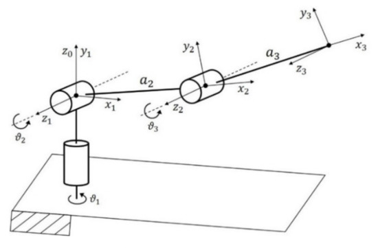
Figure 1.
Kinematic scheme reporting Denavit-Hartenberg parameters.

Table 1.
Rigid Robot Denavit-Hartenberg parameters.
2.1. Inflatable Link Model
When pressurized, the link can be considered as a beam, since the pre-stress due to the pressure supply stiffens the structure. In [23] the displacement along an inflatable beam is calculated as:
where is the external shear force acting at the distance from the joint, is the Young modulus, is the shear modulus, is the normal force acting on each cap that depends on the internal pressure and the radius , is the cross-section area that depends on the wall thickness , is the second moment of area, and is a correction shear coefficient, determined from the cross-section shape, usually set in literature for circular thin tubes, e.g., in [24].
The model can be simplified to be easily utilized for the robot control, therefore a pseudo-rigid body model [25] is used in this work, as illustrated in Figure 2. The cylindrical inflatable link, with length , is represented as two rigid bodies, having same diameter d and lengths and , such that their sum is the link length . The two bodies are connected by a hinge with a torsional spring, whose behavior is described through the Hooke’s law:
where is the spring stiffness, the angular deflection and the reaction torque.
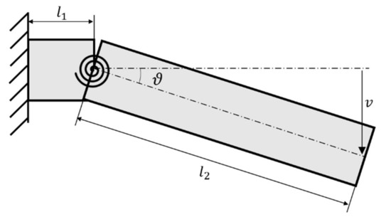
Figure 2.
Inflatable link pseudo-rigid body model, 2D scheme.
These models can be considered effective until the pressure is able to maintain the link walls stressed, otherwise the formation of wrinkles leads to the collapse of the structure. The wrinkling moment can be defined as the bending load for which the first wrinkles appear, and an increase in deflection does not produce an increase in moment. Several formulations and approaches are available in literature for the wrinkling moment estimation [26]. For the goals of this work, the following formulation by Wielsgosz et al. [27] is considered to define the wrinkling moment :
2.2. Robot Kinematic Model
The inflatable link model is adopted to improve the simple robot model introduced before, allowing to consider the deflections due to the soft structures. The link model is extended to evaluate the deflections along two orthogonal axes, neglecting the torsional deformations. Therefore, two torsional springs are considered for each link. The introduction of the pseudo rigid body model for the inflatable links adds additional uncontrolled degrees of freedom at the entire robotic arm. The robotic arm reaches 7 degrees of freedom: 3 for the actuated joints and 2 for each link introduced by the virtual springs. A 3D representation of the robot is shown in Figure 3.
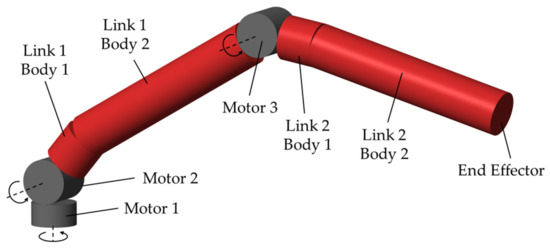
Figure 3.
Robot 3D Model.
The new kinematic model is shown in Figure 4, and the D-H parameters are explicated in Table 2. The joint variables are divided in motor joint variable and virtual spring joint variables . In all this work the notation with the subscript m indicates the motor-associated components and k indicates the spring-associated components .
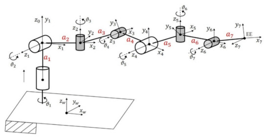
Figure 4.
Kinematic scheme with additional degrees of freedom.
Table 2.
Flexible Robot Denavit-Hartenberg parameters.
2.3. Load and Pose Estimation
To study the behaviour of the flexible robot, it is essential to estimate the external load acting on the system. In this way, the deformation of the flexible link can be calculated, and the pose estimation can be performed.
The motor torques and positions are considered as known parameters. In a real case, appropriate sensors can be used to provide these quantities. The external forces act on the robot end-effector (EE) and the external torques are assumed null . The virtual springs have all the same stiffness , as the system is assumed to be orthotropic. In addition, space application is considered, so weight force is set to zero in the algorithm.
An elastostatic approach is adopted to solve the problem. The Jacobian matrix is , with
where is given by the third column of the rotation matrix , is the position of the EE and is the position of the joint , expressed in the operating system. The following equation is valid:
where is the torque vector and represents the external load. Considering only the motor torques , it is:
where . Finally, for the inflatable link model, reclaiming (2):
where are the virtual spring torque.
Using the (5–7), a recursive algorithm is developed, as illustrated in Figure 5. It needs as input the motor torques and positions and the virtual spring stiffness , and it estimates the external load , the joint variable related to the link deformations and relative torques .
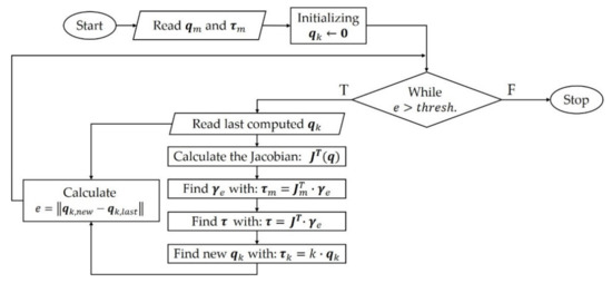
Figure 5.
Load and Pose Estimation Algorithm.
2.4. Elastostatic Inverse Kinematics
In the previous subsection, an algorithm to evaluate the deformations of the flexible structure and the forces acting on the EE, knowing only the value of motor torques and positions, has been proposed. Assuming the same hypotheses, the problem of positioning the EE from the starting point to the end point , with certain speed , is approached. In this case, the load is considered known and constant.
Figure 6 shows how the algorithm works. It can be divided in two main parts: first, the motor joint variables are calculated to be used for the motor control; then, the virtual spring joint variables are estimated, given the external load and the virtual spring stiffness , though a recurrent algorithm, based on the same elastostatic approach previously described.
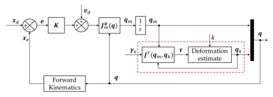
Figure 6.
Recursive algorithm for inverse kinematics and state estimation using an elastostatic approach.
Once the deformations are estimated, the vector of all the joint variables is built to perform the forward kinematics and calculate the expected EE position , to be compared with its set value . The error can be calculated and multiplied by the symmetric positive definite matrix , that can be tuned to enhance the performance.
Having defined the right pseudo-inverse of the Jacobian matrix:
the joint velocity variables can be calculated with:
where is a [] dimension matrix composed by the 3 motor-associated rows of .
Finally, throughout numerical integration, the inverse kinematics is completed by calculating the motor joint variable .
Therefore, this algorithm allows the robot to reach a point in the workspace by calculating the deformation of the inflatable links and consequently considering them to modify the set rotations of the actuated joints.
3. Inflatable Link Prototype and Characterization
A prototype of the inflatable link has been designed to have a cylindrical shape and good air pressure resistance. It consists in a soft cylindrical polyvinyl chloride (PVC) coated fabric, closed by two stiff PVC caps each of them secured by a seal and a metal band to ensure cohesion and avoiding air losses. Compressed air is supplied throughout one of the rigid caps. The link has a length , radius and wall thickness is .
An experimental set-up has been arranged to perform the static characterization, analysing the link as a cantilever. The purpose of the tests is to evaluate the static performance of the link as a function of inflation pressure, evaluating the stiffness constant , that appears in the robotic arm model. The main set-up of the components is shown in Figure 7.
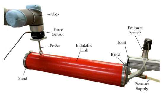
Figure 7.
Cantilever beam, experimental set-up.
The inflatable link is fixed to a rigid structure, and the internal pressure is measured by a pressure sensor. During a single test, the pressure is maintained constant by a pressure regulator. In order to ensure the repeatability of the test condition a UR5 robot is used to impose the link a position set , that involves an angular deflection , as schematized in Figure 8.
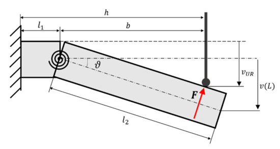
Figure 8.
Static test for stiffness estimation, experimental set-up.
The zero position corresponds to the rest position. The contact between the UR5 and the link takes place through a probe, allowing to better identify the distance from the fixed joint and the axis of the probe, having minimized the contact surface. During the tests, the UR5 end-effector moves orthogonally with respect to the initial axis of the inflatable link. The exchanged forces are measured by a force sensor.
4. Results
The experimental tests were carried out with constant inflation pressure value, considering pressures in the p = 10–60 kPa range. During the tests, the first wrinkle has occurred at the distance mm from the fixed joint, so it can be considered in the link model as the length of the first body. Having set the distance mm for each test, through trigonometric considerations, the angular deflection and the torque can be calculated, assuming small-angle approximation, from the recorded force and the position set .
Results are plotted in Figure 9. According to the experimental data, the stiffness characteristic below the theoretical wrinkling moment value, given by (2), can be approximated as linear. The inflatable link linear model can be considered valid until . Consequently, for each test, a linear regression of the points below wrinkling conditions is performed to evaluate the stiffness k. The average torque of the points over wrinkling conditions allows to trace a characteristic for the entire range of the examined angles, assuming as a saturation value. Results are summarized in Table 3, where the estimated stiffness with its standard deviation , the theoretical wrinkling moment and the average maximum experimental torque are reported.
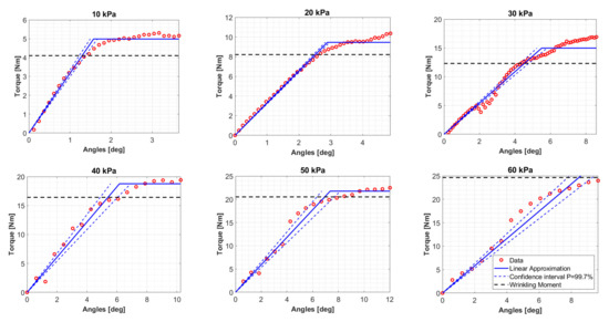
Figure 9.
Experimental data and linear model on varying pressures for the considered inflatable link.
Table 3.
Results from the inflatable link characterization.
The experimental maximum moment follows the trend of the theoretical wrinkling moment . The internal pressure establishes the wrinkling moment, and so the maximum torque the link can support. On the other hand, the estimated values do not show a clear correlation with the pressure, and their variations in the range 155.89–187.30 Nm/rad could be due to the quality of the support. This result is consistent with the prediction from Equation (1).
Using the average of the stiffness values Nm/rad, a characteristic of the link is built, making it possible to estimate the unknown Young’s modulus of the PVC coated fabric, knowing the features of the link, and setting the pressure. The computed values of the Young’s modulus result in the range E = 136–140 MPa for pressures from 10 kPa to 60 kPa, hence its dependence on pressure in this range can be considered negligible.
In Figure 10 the configurations of the soft robot during a movement of the EE from a starting point to an end point , following a planned trajectory, using the elastostatic inverse kinematics algorithm, are shown. The simulation utilizes as stiffness the average of experimental stiffness values and as external load a sample value N.
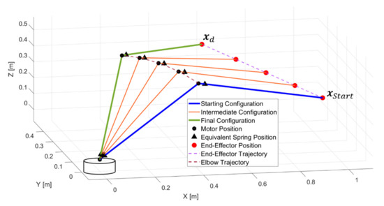
Figure 10.
Results of elastostatic inverse kinematics algorithm.
The robot model effectively follows the planned trajectory, setting the rotations of the motor joints to compensate the deformations of the inflatable links. This aspect is underlined in Figure 11, where the values of motor joints angles computed by the elastostatic algorithm are compared with those defined by a rigid body reverse kinematic algorithm.
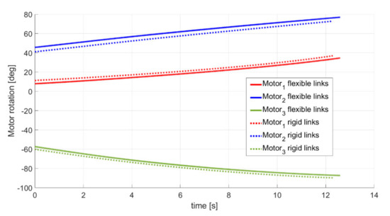
Figure 11.
Motor joint variable set in the case of robot with flexible and rigid links.
During the simulation, the maximum moments acting on the links are identified and compared to the experimental data to find the minimum internal pressure required to ensure the validity of the model. Supposing both links have same features and internal pressure, having on the link 1 a maximum moment of Nm, resulting from the combination of the torques acting on the two orthogonal virtual springs, the pressure should be kPa.
5. Conclusions
This manuscript introduces the concept of an articulated soft robot with two inflatable links and three degrees of freedom. Its lightness and capability to be contained in a relatively small package when deflated, makes the robot suitable for space applications.
The prototype of the inflatable link, made of PVC-coated fabric, was tested and statically characterized, using a linear pseudo-rigid body model. The model proposed is considered valid until the pre-stress point, when due to the pressure, the fabric walls are stiffened, making it possible to thereafter consider the link as a beam. Results evidence that the validity limits of the model depend on the inflation pressure, while this value does not influence the stiffness of the link until it remains in the 10–60 kPa range.
Recurrent algorithms for the pose and load estimation and to build the inverse kinematics of the manipulator were developed. Data from the characterization tests of the link prototype were considered and implemented in the robot model to evaluate the deformations due to the inflatable nature of the links. The presented methodology, based on an elastostatic approach, can calculate the sets for motor joint rotations, compensating the link deformations, for precise trajectory planning.
This work represents a preliminary analysis to be further developed. A dynamic model and more advanced control system of the robot is under development, as well as the design of the prototype of the full robot.
Author Contributions
Conceptualization, M.T., M.G., P.P. and S.M.; methodology, M.T., M.G., P.P. and S.M.; software, M.T., M.G. and P.P.; validation, M.T., M.G., P.P. and S.M.; formal analysis, M.T., M.G., P.P. and S.M.; investigation, M.T., M.G. and P.P.; resources, S.M.; data curation, M.T., M.G. and P.P.; writing—original draft preparation, M.T., M.G. and P.P.; writing—review and editing, M.T., M.G., P.P. and S.M.; visualization, M.T., M.G., P.P. and S.M.; supervision, S.M.; project administration, S.M.; funding acquisition, S.M. All authors have read and agreed to the published version of the manuscript.
Funding
This research received no external funding.
Institutional Review Board Statement
Not applicable.
Informed Consent Statement
Not applicable.
Data Availability Statement
Data is contained within the article.
Conflicts of Interest
The authors declare no conflict of interest.
References
- Feifei, C.; Wang, M.Y. Design Optimization of Soft Robots: A Review of the State of the Art. IEEE Robot. Autom. Mag. 2020, 27, 27–43. [Google Scholar]
- Hughes, J.; Culha, U.; Giardina, F.; Guenther, F.; Rosendo, A.; Iida, F. Soft Manipulators and Grippers: A Review. Front. Robot. AI 2016, 3, 3. [Google Scholar] [CrossRef]
- Fenci, G.E.; Currie, N.G. Deployable structures classification: A review. Int. J. Space Struct. 2017, 32, 112–130. [Google Scholar] [CrossRef]
- Cadogan, D.; Sandy, C.; Grahne, M. Development and evaluation of the mars pathfinder inflatable airbag landing system. Acta Astronaut. 2002, 50, 633–640. [Google Scholar] [CrossRef]
- Freeland, R.; Bilyeu, G.; Veal, G.; Steiner, M.; Carson, D. Large inflatable deployable antenna flight experiment results. Acta Astronaut. 1997, 41, 267–277. [Google Scholar] [CrossRef]
- Williams, G.T.; Malone, P.K.; Jankowski, F.J.; Vendura, G.J., Jr. Developing an Inflatable Solar Array; DTIC: Fort Belvoir, VA, USA, 1992. [Google Scholar]
- Puig, L.; Barton, A.; Rando, N. A review on large deployable structures for astrophysics missions. Acta Astronaut. 2010, 67, 12–26. [Google Scholar] [CrossRef]
- Giannaccini, M.E.; Xiang, C.; Atyabi, A.; Theodoridis, T.; Nefti-Meziani, S.; Davis, S. Novel Design of a Soft Lightweight Pneumatic Continuum Robot Arm with Decoupled Variable Stiffness and Positioning. Soft Robot. 2018, 5, 54–70. [Google Scholar] [CrossRef] [PubMed]
- Kim, H.-J.; Kawamura, A.; Nishioka, Y.; Kawamura, S. Mechanical design and control of inflatable robotic arms for high positioning accuracy. Adv. Robot. 2017, 32, 89–104. [Google Scholar] [CrossRef]
- Mengacci, R.; Angelini, F.; Catalano, M.G.; Grioli, G.; Bicchi, A.; Garabini, M. On the motion/stiffness decoupling property of articulated soft robots with application to model-free torque iterative learning control. Int. J. Robot. Res. 2020. [Google Scholar] [CrossRef]
- Palacio, J.M.A.; Riwan, A.; Mechbal, N.; Monteiro, E.; Voisembert, S. A novel inflatable actuator for inflatable robotic arms. In Proceedings of the 2017 IEEE International Conference on Advanced Intelligent Mechatronics (AIM), Munich, Germany, 3–7 July 2017; pp. 88–93. [Google Scholar]
- Walker, J.; Zidek, T.; Harbel, C.; Yoon, S.; Strickland, F.S.; Kumar, S.; Shin, M. Soft Robotics: A Review of Recent Developments of Pneumatic Soft Actuators. Actuators 2020, 9, 3. [Google Scholar] [CrossRef]
- Li, X.; Sun, K.; Guo, C.; Liu, T.; Liu, H. Design, modeling and characterization of a joint for inflatable robotic arms. Mechatronics 2020, 65, 102311. [Google Scholar] [CrossRef]
- Martius, G.; Hostettler, R.; Knoll, A.; Der, R. Compliant control for soft robots: Emergent behavior of a tendon driven anthropomorphic arm. In Proceedings of the 2016 IEEE/RSJ International Conference on Intelligent Robots and Systems (IROS), Daejeon, Korea, 9–14 October 2016; pp. 767–773. [Google Scholar]
- Gillespie, M.T.; Best, C.M.; Killpack, M.D. Simultaneous position and stiffness control for an inflatable soft robot. In Proceedings of the 2016 IEEE International Conference on Robotics and Automation (ICRA), Stockholm, Sweden, 16–20 May 2016; pp. 1095–1101. [Google Scholar]
- De Luca, A.; Book, W. Robots with Flexible Elements. In Handbook of Robotics; Siciliano, B., Khatib, O., Eds.; Springer: Berlin/Heidelberg, Germany, 2016; pp. 243–282. [Google Scholar]
- Sanan, S.; Moidel, J.B.; Atkeson, C.G. Robots with inflatable links. In Proceedings of the 2009 IEEE/RSJ International Conference on Intelligent Robots and Systems, St. Louis, MO, USA, 10–15 October 2009; pp. 4331–4336. [Google Scholar]
- Oliveira, J.; Ferreira, A.; Reis, J.C. Design and experiments on an inflatable link robot with a built-in vision sensor. Mechatronics 2020, 65, 102305. [Google Scholar] [CrossRef]
- Buondonno, G.; De Luca, A. Efficient Computation of Inverse Dynamics and Feedback Linearization for VSA-Based Robots. IEEE Robot. Autom. Lett. 2016, 1, 908–915. [Google Scholar] [CrossRef]
- Best, C.M.; Wilson, J.P.; Killpack, M.D. Control of a pneumatically actuated, fully inflatable, fabric-based, humanoid robot. In Proceedings of the 2015 IEEE-RAS 15th International Conference on Humanoid Robots (Humanoids), Seoul, Korea, 3–5 November 2015; pp. 1133–1140. [Google Scholar]
- Best, C.M.; Rupert, L.; Killpack, M.D. Comparing model-based control methods for simultaneous stiffness and position control of inflatable soft robots. Int. J. Robot. Res. 2020. [Google Scholar] [CrossRef]
- Hartenburg, R.S.; Denavit, J.; Freudenstein, F. Kinematic Synthesis of Linkages. J. Appl. Mech. 1965, 32, 477. [Google Scholar] [CrossRef]
- Le Van, A.; Wielgosz, C. Bending and buckling of inflatable beams: Some new theoretical results. Thin-Walled Struct. 2005, 43, 1166–1187. [Google Scholar] [CrossRef]
- Cowper, G.R. The Shear Coefficient in Timoshenko’s Beam Theory. J. Appl. Mech. 1966, 33, 335–340. [Google Scholar] [CrossRef]
- Howell, L.L. Compliant Mechanism book. In 21st Century Kinematics; McCarthy, J., Ed.; Springer: London, UK, 2013; pp. 189–216. [Google Scholar]
- Veldman, S.; Bergsma, O.; Beukers, A. Bending of anisotropic inflated cylindrical beams. Thin-Walled Struct. 2005, 43, 461–475. [Google Scholar] [CrossRef]
- Wielgosz, C.; Thomas, J.-C. Deflections of inflatable fabric panels at high pressure. Thin-Walled Struct. 2002, 40, 523–536. [Google Scholar] [CrossRef]


Publisher’s Note: MDPI stays neutral with regard to jurisdictional claims in published maps and institutional affiliations. |
© 2021 by the authors. Licensee MDPI, Basel, Switzerland. This article is an open access article distributed under the terms and conditions of the Creative Commons Attribution (CC BY) license (http://creativecommons.org/licenses/by/4.0/).