1. Introduction
In the excavation chamber of a slurry shield tunnel boring machine (SS-TBM), bentonite slurry, composed of water, bentonite, and additional additives, is kept under pressure to stabilize the tunnel face and control the groundwater pressure. This process also enables the continuous removal of soil by mixing it with the slurry and transferring it to a separation plant, where the solids are extracted and the bentonite slurry is recycled [
1,
2,
3,
4]. However, the recycling process produces exhausted bentonite slurry, known as waste bentonite slurry (WBS), that cannot be reused and must be disposed of. The management of WBS entails high costs for the contractor and has a substantial environmental impact.
As excavation progresses, an annular gap is naturally created between the lining segments and the surrounding soil. This void must be filled through simultaneous grouting, which is essential to limit ground settlement and to lock rings into the designed position [
5]. The grouts used for this purpose are generally either mono-component or two-component formulations, with the latter being more frequently used. In a two-component grout (2CG), Component A (containing water, bentonite, cement and a retarder/fluidifying agent) is combined with Component B (usually a sodium silicate solution), which triggers rapid gelation and hardening. Bentonite plays a crucial role in 2CG due to its rheological and thixotropic properties, which influence the pumpability, stability, and mechanical strength development of the grout over short curing times [
6,
7,
8].
Recent research has highlighted the importance of the circular economy regarding tunnelling projects, in which one of the main environmental and economic challenges is the management of excavated soils [
9]. The European Commission actively supports the adoption of circular economy principles, in line with the 2020 Circular Economy Action Plan [
10], and promotes the sustainable and circular reuse of excavated soil derived from construction sites via the EU Soil Strategy for 2030 [
11]. Increased attention to sustainability based on these principles has led to the partial replacement of cement in grout mixes with industrial byproducts such as ornamental stone, slag and fly ash, as described in several studies [
12]. In parallel, researchers have explored the reuse of excavated materials. Refs. [
13,
14] showed that it was possible to use excavated materials by replacing bentonite and water in mono-component grouts. Ref. [
15] investigated two-component backfilling grouts by substituting bentonite with hydrocyclone-treated slurry, although their study used a Component A that fitted the bleeding requirements only for a high dosage of slurry (equivalent to an overdosage of bentonite). Similarly, Ref. [
16] studied the reuse of drilling waste slurry mixed with cement, bentonite, and fly ash. Their research focused on the “capsule grouting” technique for pipe jacking, an application with different rheological and mechanical requirements compared to the annular gap backfilling of shield TBMs. Despite these advances, however, the direct use of untreated WBS in 2CG for backfilling remains relatively unexplored. The aim of this study is to fill this gap by investigating the complete substitution of commercial bentonite and the partial substitution of fresh water with WBS in 2CG formulations. The effects on the unit weight, bleeding, viscosity, gel time, and mechanical strength are comprehensively examined in order to provide practical insights into the large-scale application of WBS in slurry shield tunnelling projects.
The properties of the grout obtained using WBS are also statistically analyzed and compared to those of other reference mixes using Welch’s t-test. If the calculated p-value for a given parameter is less than the significance level α (typically set at 0.05), the mean values are considered significantly different.
2. Slurry Treatment Process
In an excavation involving an SS-TBM, the excavated soil is transported from the excavation chamber to a soil treatment plant (STP) through a hydraulic circuit. The STP plays a crucial role in separating the soil particles from the bentonite slurry, thus allowing the slurry to be recirculated into the excavation chamber of the SS-TBM. The separation process is divided into stages based on particle size: first, primary vibrating screens remove coarse gravel and cobbles; following this, the use of hydrocyclones (coarse and/or fine) combined with dewatering screens guarantees efficient separation of the finer fractions. The overflow from the hydrocyclones is pumped back to the SS-TBM, while the underflow, a dense slurry concentrated with fines, is typically directed to filter presses where the residual water is squeezed out. The final products of the filter press process are solid “filter cakes”, suitable for transport by truck. The disposal of filter cakes represents an environmental problem and an economically disadvantageous aspect of this process, as it involves trucking costs, high landfill fees, and significant CO2 emissions linked to transport and earthmoving operations.
The innovative contribution of this study concerns the valorization of the bentonite slurry when it reaches the end of its operational life cycle. During excavation, the slurry is continuously treated by the STP, which removes soil particles to reduce the density of the fluid, known as a “lightening” process. However, despite this mechanical separation, ultrafine particles (silt and clay) remain in the slurry, causing a progressive increase in its density over time. When the slurry reaches a critical threshold density, typically around 1.25 kg/L, it cannot be reused for excavation, and it is considered exhaust (WBS). In view of this operational constraint, instead of sending the exhaust slurry to the filter press for disposal, it is proposed here to send WBS to the backfilling batching plant. This material, containing natural fines and spent bentonite, can be used as a primary raw material to replace fresh water and bentonite in the production of Component A for 2CG in backfilling applications.
3. Materials and Research Path
In the geotechnical field, pure bentonite is a natural clay; in tunnelling applications, however, the term “bentonite” is commonly used to indicate specific products that are mainly composed of natural bentonite and doped with additives [
17]. Natural bentonites are functionalized with additives in order to enhance their properties for specific applications. In the following, the term “bentonite” should be understood according to this latter definition.
When SS-TBMs are used for tunnel excavation, bentonite is employed for two distinct tasks:
Bentonite is used to make slurry that is injected under pressure to support the tunnel face; this balances the soil and groundwater pressures, thereby preventing collapse of the tunnel face, particularly in soft or saturated ground [
18]. Simultaneously, it plays a crucial role in the transport of spoil material: the excavated soil is mixed with the slurry and remains suspended, due to the density and thixotropy of this fluid, thereby preventing particle sedimentation and enabling efficient transport to the separation plant [
19].
Bentonite is a key ingredient in backfilling grout when 2CG is used. In grout formulations, bentonite acts as a rheological modifier and stabilizing agent: it prevents segregation of cement and water (bleeding), ensures pumpability over long distances, and guarantees the homogeneity of the mix, an essential aspect in terms of ensuring structural stability, as it results in higher strength over the short term [
8].
In order to investigate the feasibility of the reuse of WBS in 2CG, a laboratory testing campaign was carried out in two stages. In the first stage, the compatibility of bentonite employed in slurry shield applications via 2CG technology was evaluated, since unexpected chemical reactions between products expressly designed for the stability of the excavation and mucking with the other ingredients of the 2CG could not be excluded a priori. Once this compatibility was confirmed, the laboratory investigation focused on the reuse of WBS in 2CG.
The 2CG assessment was based on work by [
20]. Five bentonite products were considered in this research, and seven different mix designs were studied. All of the mix designs and the corresponding bentonites (or WBSs) are listed in
Table 1. The grouts labelled as REF 0, REF 1 and REF 2 have been thoroughly investigated in previous studies (references given in
Table 1). These mixes act as references for the comparison of new ones.
As reported above, the first step in this research was to evaluate the properties of the 2CG obtained using slurry bentonite and to compare its properties with those of standard 2CG to prove the suitability of this “hybrid 2CG” (so called because it was prepared using a bentonite designed for other applications). Mix designs REF 0, REF 1, REF 2, ID 1 and ID 2 were prepared according to the dosages listed in the “reference mix” (
Table 2).
The second step of the research focused on the reuse of WBS in the 2CG by replacing the bentonite and partially substituting the water with this mud. In the mix design in this second step (WBS ID 1 and WBS ID 2), all of the ingredients were regulated to maintain constant ratios between water/cement, water/bentonite, water/retarder-fluidifying agent, and water/accelerator, in order to permit a direct comparison of the rheological and mechanical properties across the 2CG produced with this new mix and the reference mix. Mix designs WBS ID 1 and WBS ID 2 were prepared according to the dosages listed in the “WBS mix” (
Table 2).
Portland cement type CEM I 52.5 R was employed for the preparation of the grout. The accelerator and retarder/fluidifying agents used in this study were provided by Utt Mapei. Further information concerning the bentonites previously used (for the reference mixes) can be found in the references in
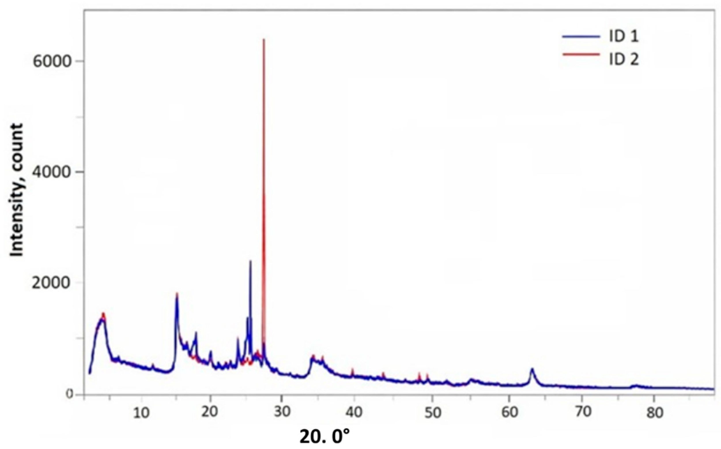
Table 1. Diffractograms from X-ray Diffraction Analysis (XRD) for the two new bentonites (used for ID 1 and ID 2 and consequently in WBS ID 1 and WBS ID 2) are shown in
Figure 1.
The soil used to simulate the solid fraction of the WBS was collected from an excavation site in Piedmont, Italy. The soil was sieved, and only the fraction finer than 0.075 mm was used (No. 200 sieve), following [
15,
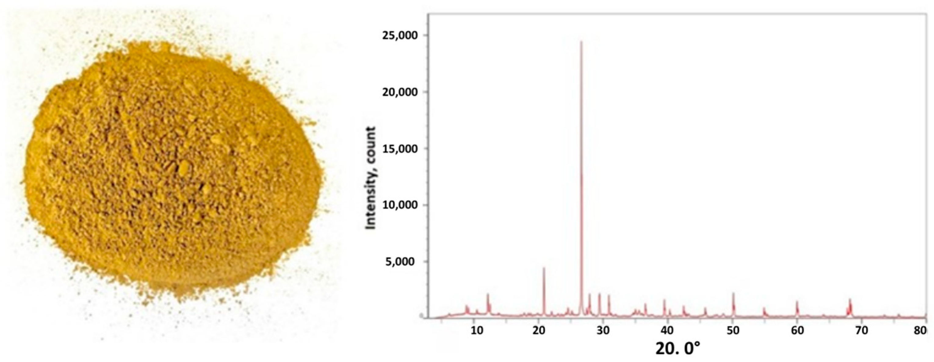
21]. This cut-off was selected to represent the silt and clay fraction that typically accumulates in the bentonite slurry during the excavation process, leading to the progressive increase in density that characterizes WBS. The mineralogical composition of the soil (% by weight) was determined to be quartz (36%), muscovite (22%), clinochlore (22%), albite (13%), and calcium carbonate (6.3%) using a Rigaku SmartLab SE XRD system operating in continuous scan mode between 4° and 84° of incidence at a constant speed of 0.1°/s. A photograph of the soil and an XRD diffractogram are shown in
Figure 2. The particle density of the soil used for metering according to
Table 2 was equal to 2.7 kg/L.
4. Preparation of Bentonite Slurry, WBS and Component A
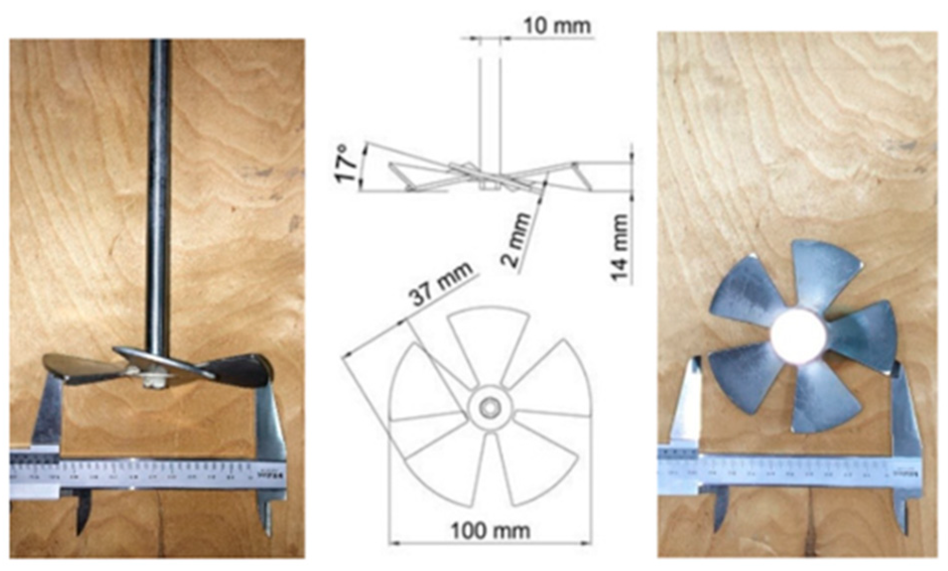
Two bentonite slurry mixes were prepared, with a bentonite concentration of 4.5% by weight. Slurries were obtained by gradually adding bentonite to water and mixing with a magnetic stirrer (AM20-D, Argo Lab, Carpi, Italy) at 2000 rpm for 15 min using the impeller shown in
Figure 3, following the work of [
22]. After 24 h of hydration, a controlled amount of soil was added to the bentonite slurry (within 1 min at 800 rpm) to achieve a final unit weight of 1.25 kg/L, and the resulting WBS was then homogenized at 2000 rpm for 8 min, as detailed in
Table 3. The threshold value of 1.25 kg/L was selected in accordance with standard construction site practice; once the density of the slurry reaches this threshold value, despite circulation in the treatment plant, it can no longer be reused and is intended for disposal. Water, cement, and a retarder/fluidifying agent were then added to produce Component A of the 2CG in accordance with [
20]. The complete mixing procedure is summarized in
Table 3.
The procedure reported by [
19] can be taken as a reference for the preparation of mix designs REF 0, REF 1, REF 2, ID 1 and ID 2 (7 min of bentonite activation in water, followed by addition of cement and further mixing for 3 min, and then addition of the retarding/fluidifying agent for the last 2 min of mixing).
Samples of hardened 2CG were produced using molds with a standardized shape of 40 × 160 × 160 mm [
23]. The casting phase was carried out following work by [
24].
5. Test
In this section, the procedures used to assess Component A, the gel time and the hardened 2CG are briefly described.
- -
Unit weight: This was determined using a mud balance in accordance with ASTM D4380 [
25], with a resolution of 0.01 g/cm
3.
- -
Viscosity: This was assessed using a Marsh funnel in accordance with UNI 11152-13 [
26]. The discharge time for 1 L of grout was measured with an accuracy of 1 s.
- -
Bleeding: This was determined in accordance with UNI 11152-11 [
27]. The bleeding index can be computed as follows:
where V
w is the volume of water segregated at the top of the sample, and V
sample is the initial sample volume (1 L). Tests were performed after 1, 3, and 24 h.
- -
Gel time: This was measured following [
20] and is expressed in seconds.
- -
Surface compression strength (SCS): This was assessed after 1 and 3 h using a SAUTER GmbH dynamometer (1000 N max, 0.5 N resolution) with circular bit area A = 177.9 mm
2, according to the procedure described by [
24].
- -
Uniaxial compressive strength (UCS) and tensile strength (T
0): These were tested according to [
23] after one and 28 days of curing. Samples were demoulded after 24 h; specimens intended for 28-day testing were cured in water at 23 ± 2 °C prior to testing.
After assessing the various forms of Component A, mix design WBS ID 1 was discarded due to its clear unsuitability for 2CG applications.
6. Results
The results are presented according to the testing protocol described in the previous section. Firstly, the unit weight, viscosity, and bleeding data for Component A are discussed, and this is followed by determinations of the gel times. A mechanical characterization based on SCS, T0, and UCS is then given for different curing times.
It should be noted that data on REF 0, REF 1 and REF 2 are taken from previous studies, with the references given in
Table 1. The experimental data were processed to provide a rigorous quantitative assessment of the performance of the WBS ID 2 grout compared to reference standards and mix IDs. For the mechanical tests, the results are reported as the mean value ± standard deviation. Each data point represents the average of at least three independent determinations, in order to ensure statistical representativeness and to mitigate the effect of potential experimental outliers. The coefficient of variation (CV) was checked for each test, as it provided a quality indicator: a low CV value confirms the homogeneity of the mixture, and hence the repeatability of the preparation and curing process performed in the laboratory.
Due to the intrinsically heterogeneous nature of WBS compared to standard commercial bentonites, the assumption of equal variances (homoscedasticity) between the two could not be made a priori. Consequently, to verify the statistical significance of the differences observed, Welch’s t-test (assuming unequal variances) was adopted, with a significance level set at 95% (α = 0.05). Hence, performance variations that produced a p-value less than 0.05 (p < 0.05) were interpreted as statistically significant, allowing for the exclusion of random sampling variability as the cause of such differences. Although complying with standard geotechnical testing procedures, the number of samples limits the overall statistical power. Therefore, the statistical significance reported herein should be interpreted as an indicative trend supporting physical observations, rather than an absolute predictive metric.
6.1. Unit Weight
Table 4 reports the unit weight measurements for the tested samples of Component A. A clear distinction can be observed between the reference/ID mixes and the WBS mixes. The standard formulations (REF 0, REF 1, REF 2, ID 1, and ID 2) exhibit unit weights ranging from 1.15 to 1.18 kg/L. In contrast, the WBS-based grouts (WBS ID 1 and WBS ID 2) show significantly higher values, reaching 1.31 and 1.32 kg/L, respectively. This variation is a direct consequence of the mix design and the intrinsic nature of the WBS. While standard grouts are composed only of water, cement, bentonite, and chemical admixtures, the WBS mixes incorporate a substantial amount of excavated soil (silt and clay) suspended in the bentonite slurry. It should also be noted that the density data of WBS ID 1 is only the initial value and is not applicable to subsequent performance comparisons.
6.2. Viscosity
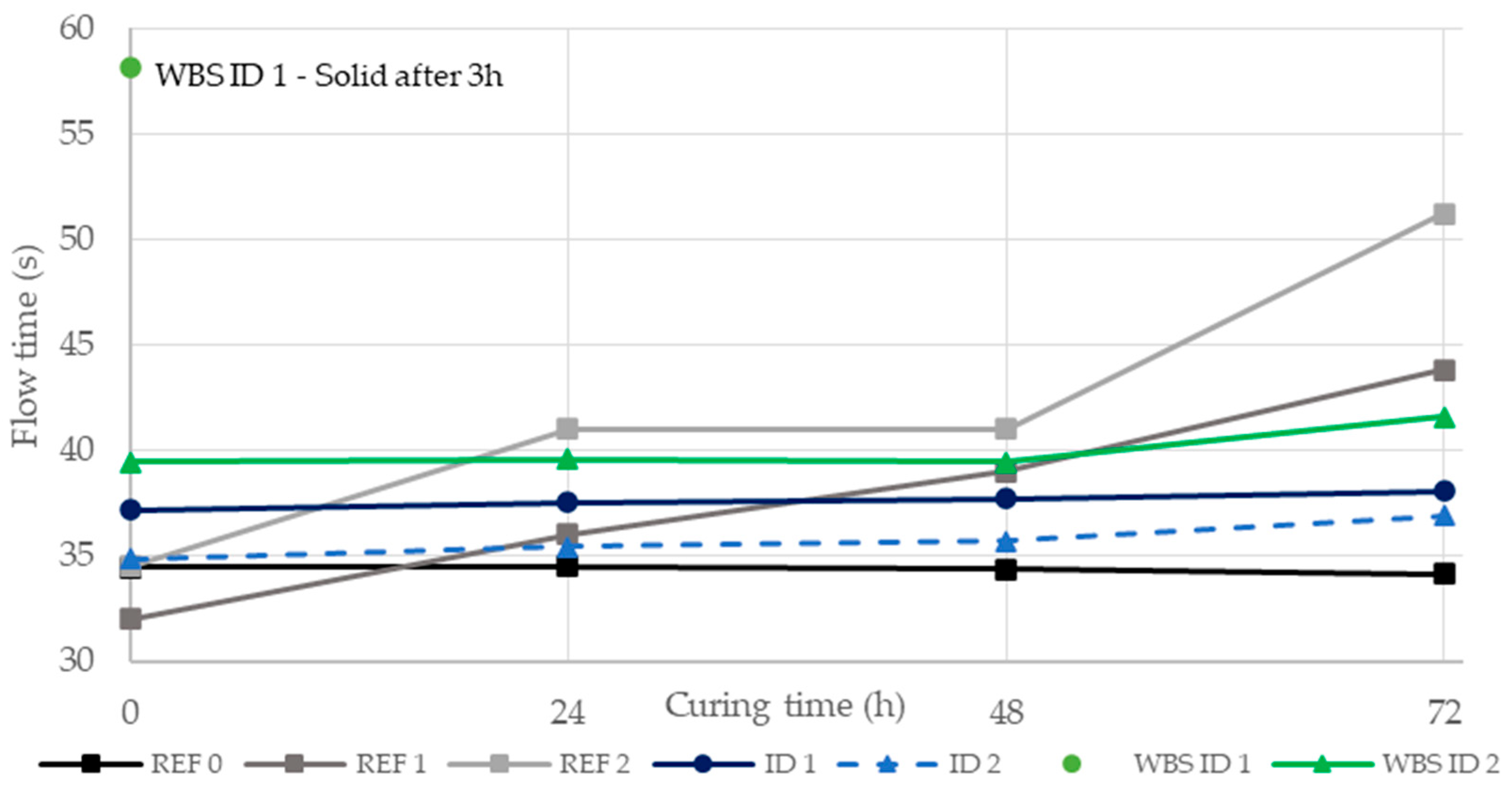
Figure 4 shows the Marsh funnel flow time results for the tested grout samples over 72 h of curing. The reference mixes REF 1 and REF 2 showed a moderate increase in viscosity with curing time, remaining within the range 32–51 s. REF 0 had a constant viscosity, close to 34 s. The ID mixes and WBS ID 2, in contrast, maintained a constant viscosity during the curing period, over a range of 35–42 s. We note that the mix WBS ID 1 was tested only at 0 h, as it had already solidified and could not be measured at 24 h and subsequent times.
6.3. Bleeding
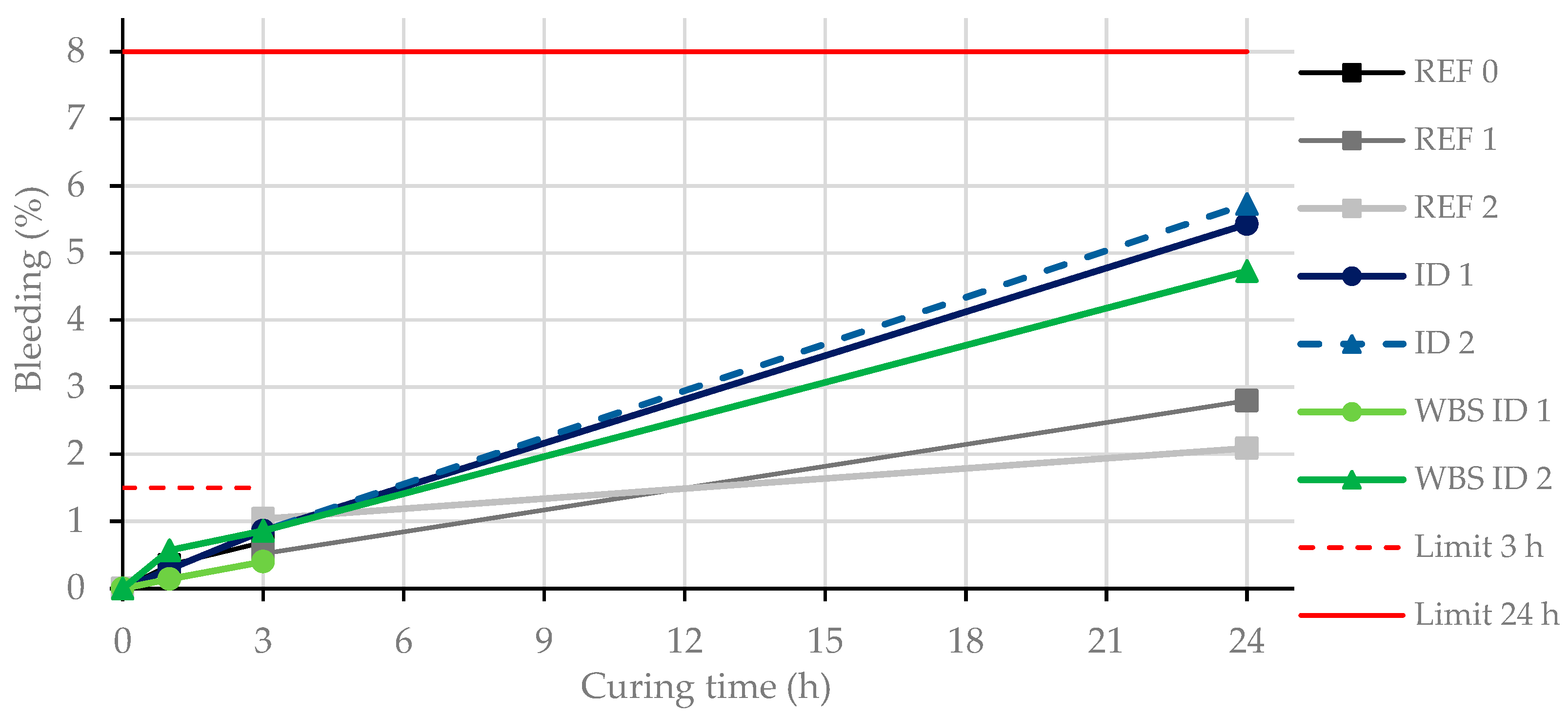
Figure 5 illustrates the evolution of bleeding over 24 h of curing time. The reference mixes (REF 1 and REF 2) showed a typical progressive increase, reaching values of between 2.1% and 2.8% after 24 h. Conversely, ID 1 and ID 2 exhibited higher cumulative bleeding, reaching values of 5.4% and 5.7%, respectively, indicating a relative reduction in the physical stability. WBS ID 2 demonstrated intermediate behaviour, with a final bleeding value of 4.7%. Notably, all of the tested mixtures remained well below the stability thresholds proposed in the literature and satisfied both the 1.5% limit at 3 h [
8] and the 8% limit at 24 h [
28]. WBS ID 1 showed an anomalously low bleeding evolution, with values of close to zero up to 3 h. No further bleeding evaluation was possible due to the solid state of the material. According to the authors’ experience, the total lack of free water after 3 h of curing needs attention, even if, in most cases, it does not represent a critical issue. On the one hand, the dosage of bentonite could be too high (and it should be re-calibrated in order to ensure the physical stability within the above-reported values of bleeding); on the other hand, premature hardening should be ruled out. In this specific case, we observed a fast early hydration, likely caused by a chemical incompatibility between the soil and the ID 1 bentonite.
6.4. Gel Time
All gel time tests were conducted using a fixed volume ratio of Component B to Component A of 6.38%.
Table 5 summarizes the gel times for all grout mixes. The REF and ID mixes exhibited gel times in the range of 7–11 s.
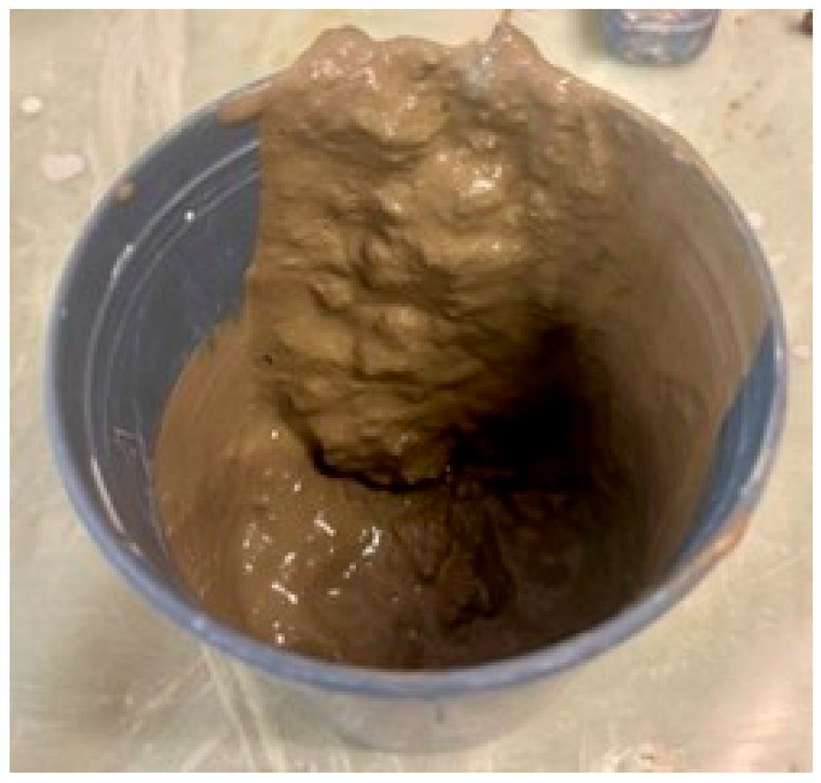
Of the WBS mixes, WBS ID 2 showed a comparable gel time (7 s), consistent with adequate reactivity and homogeneity. In contrast, WBS ID 1 displayed the shortest measured gel time, but the gel formation was markedly non-homogeneous, characterized by gel nuclei and a non-uniform matrix, as can be seen in
Figure 6.
6.5. Surface Compression Strength
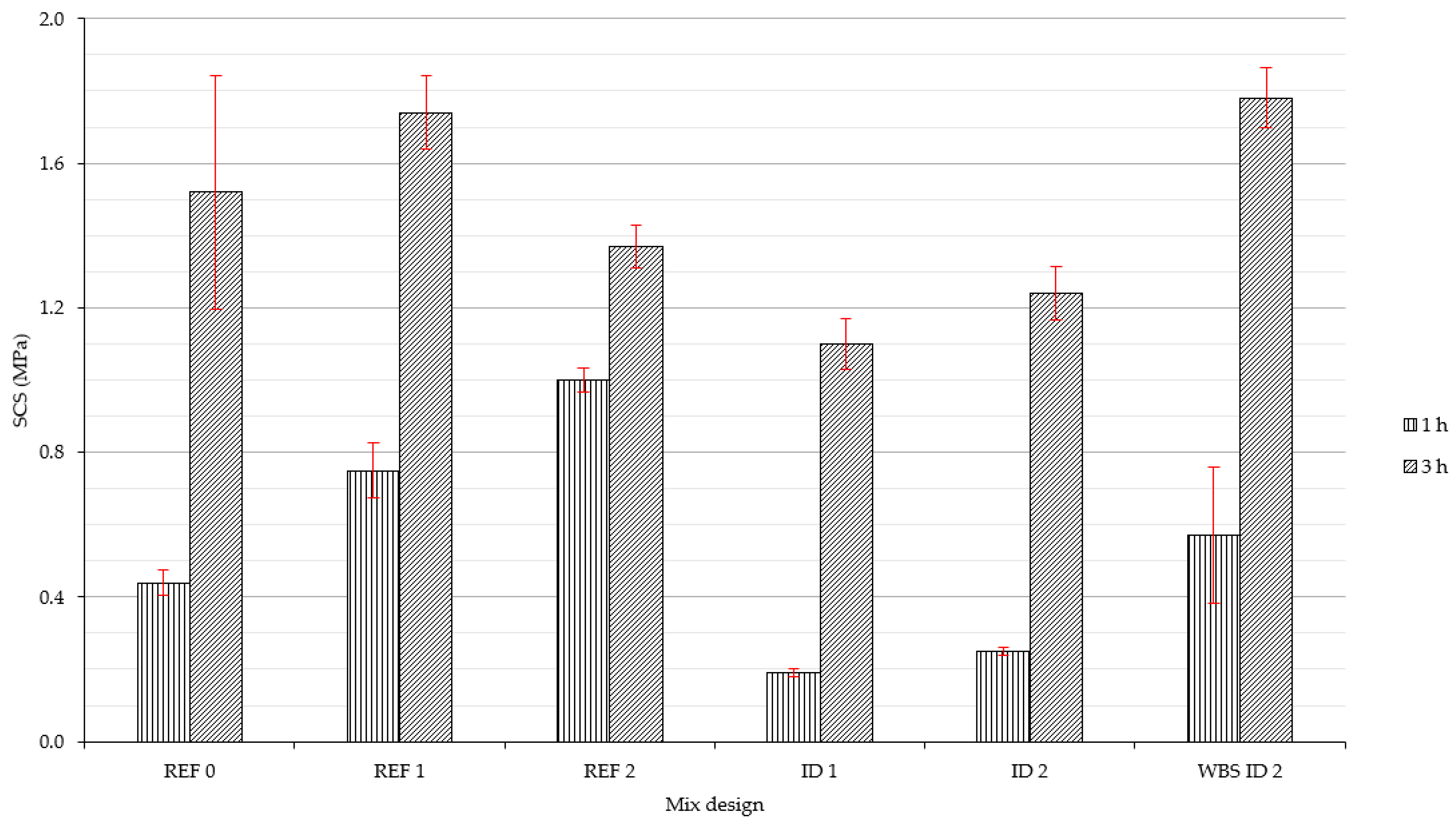
Values of the surface compression strength (SCS) after 1 and 3 h are reported in
Table 6 and
Table 7, respectively.
Figure 7 shows all of the data. The reference mixes (REF 0, REF 1, REF 2) had SCS values of between 0.4 and 1.0 MPa after 1 h, increasing to a range of 1.4 to 1.7 MPa at 3 h. ID 1 and ID 2 had lower SCS values over both time intervals compared to the references. This suggests that these formulations develop mechanical strength differently from the reference 2CG.
In contrast, WBS ID 2 exhibited a higher early strength compared to the equivalent ID mixes, with a mean value of 0.57 MPa at 1 h. The difference from ID 2 (0.25 MPa) was confirmed to be statistically significant by a Welch’s t-test (p = 0.009). However, at this early stage, the WBS mix showed a high CV (0.33), indicating larger dispersion of the results.
At 3 h, the value for WBS ID 2 reached 1.78 MPa, meaning that this outperformed all the other mixes. A statistical analysis confirmed the significance of this increment compared to REF 2 (p = 0.003) and ID 2 (p = 0.002). Furthermore, the variability of the WBS ID 2 drastically decreased at 3 h (CV = 0.05), indicating stabilization of the hardening process. This specific trend, lower initial strength at 1 h followed by a significant increase at 3 h, is not common. It could be potentially explained by a two-stage mechanism. Initially, the high surface area of the WBS fines adsorbs water, temporarily retarding the early hydration. Subsequently, the physical “filler effect” becomes dominant: the fines optimize particle packing and refine the microstructure, yielding a denser matrix that rapidly outperforms the standard mixes. Further analysis is needed to confirm the statement.
6.6. Tensile Strength
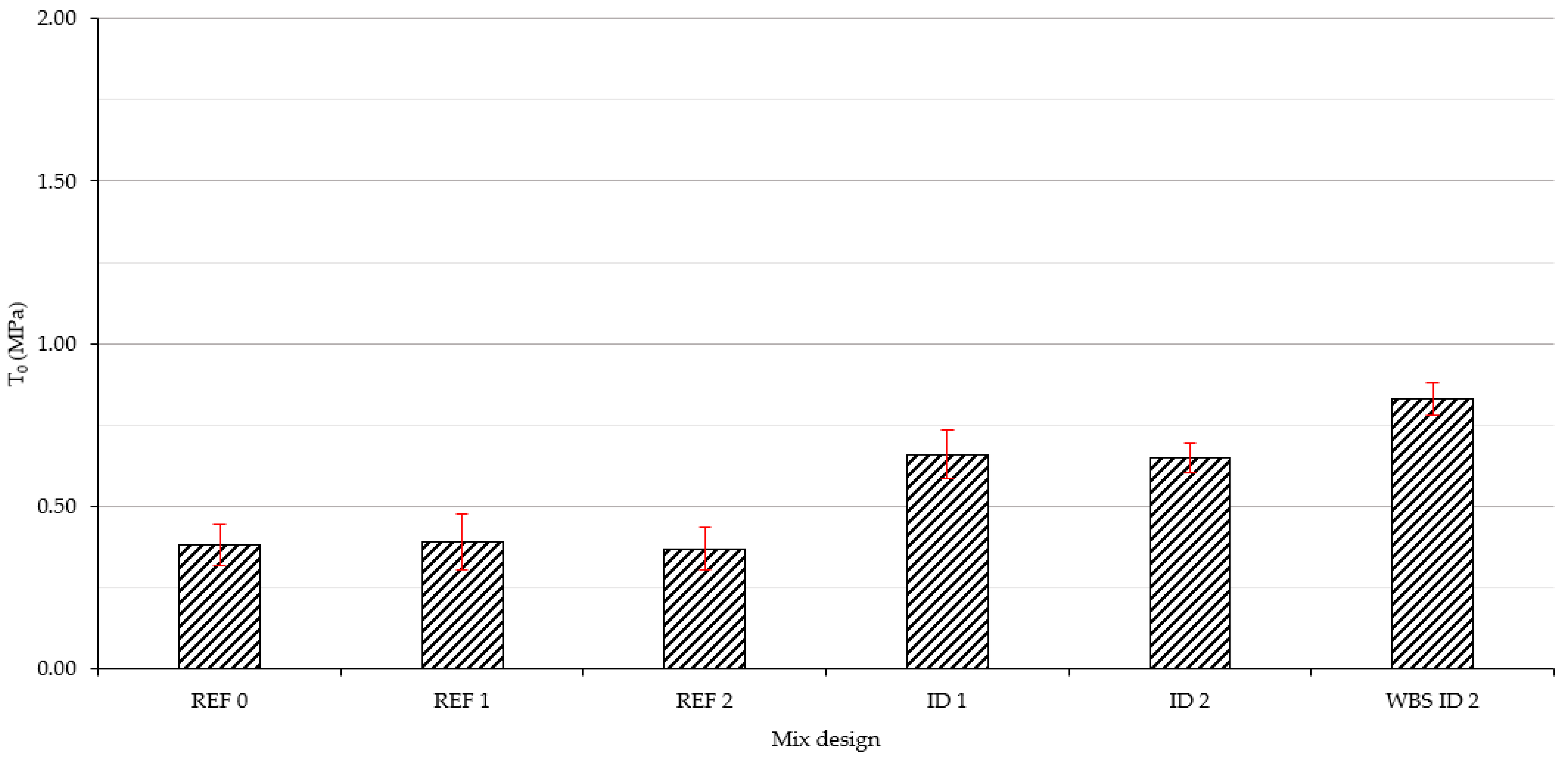
Table 8 and
Figure 8 present the values for the tensile strength of the grouts after 28 days of curing. The reference mixes (REF 0, REF 1, REF 2) achieved similar performance, with mean values of around 0.37–0.39 MPa. However, these standard mixes showed a relatively high dispersion of results, with values for the CV ranging between 0.17 and 0.21. In contrast, ID 1 and ID 2 achieved mean strengths of 0.66 MPa and 0.65 MPa, respectively. The WBS ID 2 mix achieved the highest performance, with a mean value for T0 of 0.83 MPa. A statistical analysis provided robust validation of these results. The superiority of WBS ID 2 over the reference grouts was highly significant, with Welch’s
t-test yielding
p-values consistently below 0.001 (
p < 0.001 for REF 0 and REF 1,
p = 0.001 for REF 2). Furthermore, WBS ID 2 exhibited homogeneity, as reflected by the lowest value of CV = 0.06, indicating a stable and repeatable structure.
6.7. Uniaxial Compressive Strength
Table 9 and
Table 10 and
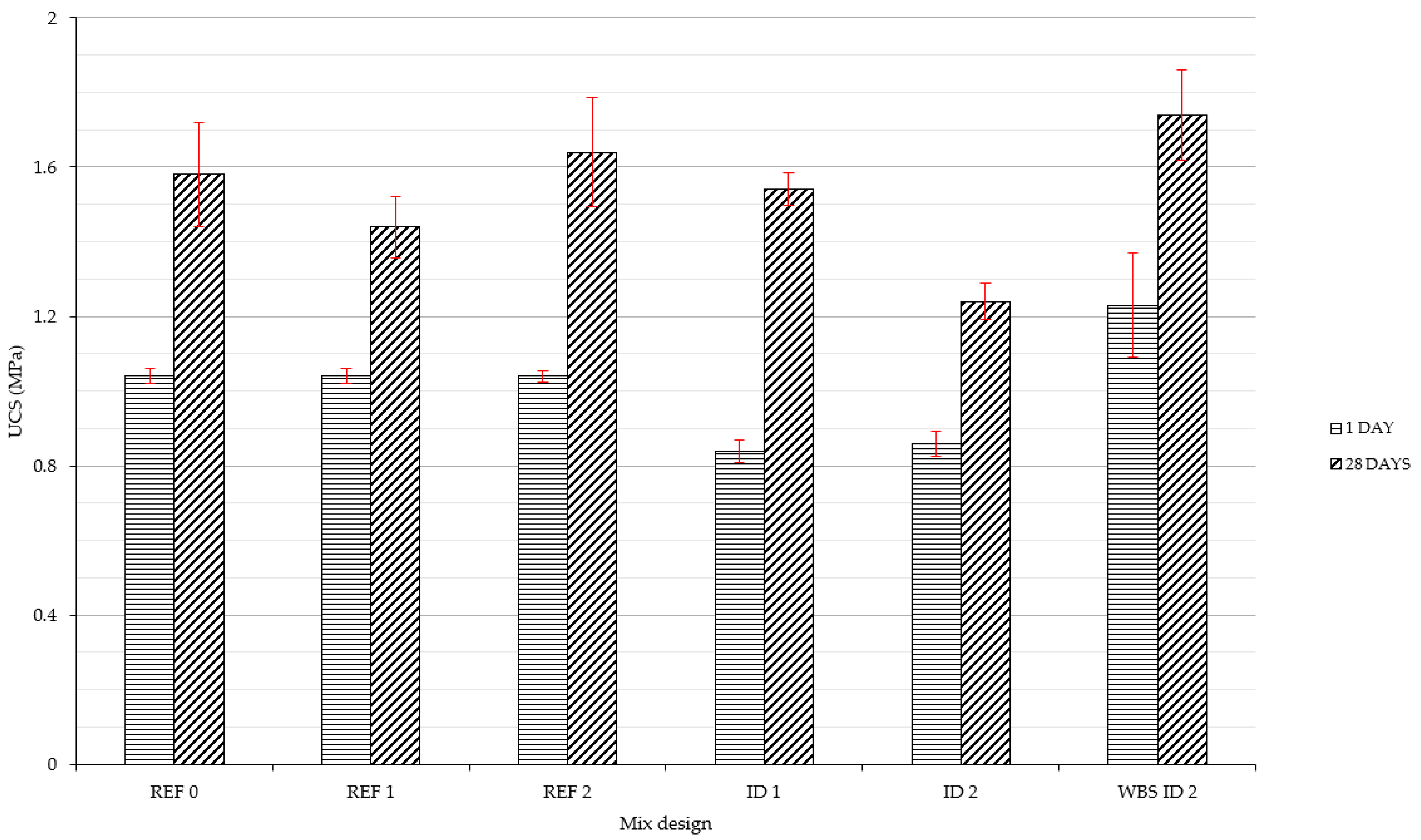
Figure 9 present the UCS values for the grout formulations after one and 28 days of curing. After one day, the reference samples (REF 0, REF 1, REF 2) showed consistent strengths of approximately 1.04 MPa. Conversely, the ID mixes exhibited lower early strength development, with mean values of 0.84 and 0.86 MPa. The WBS ID 2 mix yielded higher early performance, with a mean UCS value of 1.23 MPa. A statistical analysis confirmed that this improvement was highly significant compared to both the reference mixes (
p = 0.001) and the ID mixes (
p < 0.001). However, consistent with the trend observed in the SCS tests, the WBS mix showed a higher CV after one day, with a value of 0.11, indicating wider dispersion in the early strength results compared to the reference mixes, which had a value of CV = 0.02.
After 28 days, the UCS values for the reference mixes ranged between 1.44 and 1.64 MPa, while the ID mixes showed differing performance (1.24 MPa for ID 2 and 1.54 MPa for ID 1). The WBS ID 2 mix confirmed its good performance trend, with a mean value of 1.74 MPa. A Welch’s t-test highlighted the statistical significance of this result compared to its direct counterpart ID 2 (p < 0.001), proving that the addition of WBS actively contributes to the long-term structural matrix. In comparison with the standard formulations, the WBS mix proved to be statistically superior to REF 1 (p = 0.001) and REF 0 (p = 0.015). A p-value of 0.198 indicates that the WBS grout achieves statistically comparable mechanical performance to REF 2. Finally, at 28 days, the variability of the WBS ID 2 mix dropped to CV = 0.07, falling perfectly within the stability range for the reference mixes (0.06–0.07).
7. Simplified Sustainability Analysis
After the laboratory tests, a simplified preliminary calculation was performed to estimate the environmental benefits of the WBS ID 2 grout. The reference scenario involved a standard tunnel excavation via an SS-TBM with a 10 m diameter and a 0.15 m annular gap. In this scenario, for 1 km of tunnel, the theoretical consumption of 2CG is approximately equal to 4640 m3 (Vgrout).
A comparison of the reference mixes and the WBS ID 2 mix design shows a clear advantage: using 257 kg/m
3 of WBS allows for a reduction in the Portland cement from 230 to 208 kg/m
3 (Δ = 22 kg/m
3). To keep the assessment conservative, the carbon footprint calculation took into consideration only this cement reduction, and other potential savings (such as fresh water and bentonite) were neglected. Based on an emission factor (EF) of 0.93 kgCO
2eq/kg for CEM I [
29], the use of WBS in Component A of the 2CG, over 1 km of tunnel, gives approximately the following savings:
Moreover, recycling WBS on site prevents 1200 tons of filter cakes from entering landfills for each kilometre of excavation. This eliminates about 60 truck trips (assuming a capacity of 20 tons), which directly cuts local traffic and associated CO2 emissions.
8. Remarks
This experimental campaign demonstrated the possibility that WBS can be successfully used in 2CG formulations. From the first phase of the test campaign, it was clear that bentonite products specifically designed for slurry production for excavation purposes are not an optimal choice for 2CG applications. An analysis of the results showed that although Component A, based on ID 1 and ID 2, had a gel time, viscosity, unit weight, and bleeding characteristics comparable to those of REF 0–2, significant differences were observed in both SCS and UCS. In particular, the 2CG mixtures corresponding to ID 1 and ID 2 exhibited lower mechanical performance compared to REF 0–2. Nevertheless, the minimum technical specifications commonly set for tunnelling construction sites [
28] were satisfied, and consequently, the second phase of the research, based on WBS ID 1 and 2, was carried out.
In terms of physical properties, the WBS ID 2 mix showed a higher unit weight compared to the reference and ID mixes, due to the high solid soil content present in the slurry. Regarding the operational implications, an increase in unit weight implies a denser and heavier material, which could theoretically require slightly higher pumping pressures over long distances. However, the pumpability of a grout is primarily governed by its rheological properties, namely viscosity and physical stability (bleeding). As discussed in the following sections, WBS ID 2 maintains constant viscosity and bleeding values well below the stability thresholds. Therefore, the higher specific gravity of the WBS mix does not adversely impact its overall pumping performance, provided that the site’s pumping equipment is calibrated for a slightly heavier fluid. Distinct rheological behaviors were observed between the two bentonites tested: the reference and ID mixes showed stable viscosity and bleeding values, whereas WBS ID 1 exhibited rapid gelification and unstable bleeding, meaning that it would be unworkable on site. WBS ID 2, on the other hand, maintained constant viscosity and gel time values comparable to the standard mixes, confirming its suitability for pumping operations.
Mechanical testing highlighted that WBS ID 2 achieved better early and long-term strength compared to the REF and ID mixes, with UCS values reaching 1.23 MPa at one day and 1.74 MPa at 28 days. At 28 days, WBS ID 2 had a strength that was 10%, 16%, 6%, 13%, and 40% higher than for REF 0, REF 1, REF 2, ID 1, and ID 2, respectively. This improvement is particularly significant since the bentonite used for ID 2 and WBS ID 2 was the same; the only difference was the addition of soil to WBS ID 2, which clearly contributes positively to the mechanical properties. A statistical analysis validated these increases. At 28 days, the performance of WBS ID2 proved to be significantly higher than the equivalent ID 2 mix (p < 0.001). Regarding the reference mixes, although the 6% difference in strength compared to REF 2 was not statistically significant, such a variation falls perfectly within the acceptable tolerances for TBM backfilling operations, confirming the full functional equivalence of the material. Moreover, the low value for the CV (0.07) confirms that the material was homogeneous and reliable.
One possible explanation for this superior performance is that the increased presence of fine particles, which were introduced with the WBS, acted as a physical filler, improving the particle packing density and reducing porosity without interfering with the typical chemical reaction of the 2CG technology. This filler effect has already been recognized as a key factor for strength improvement in cementitious materials [
12]. Moreover, the presence of fine particles can contribute to microstructural refinement, creating a denser and more homogeneous matrix that limits bleeding [
30], as observed for WBS ID 2 compared to ID 2. Another plausible hypothesis is that the chemical interactions between the cement and reactive minerals contained in the fines could promote the formation of additional cement hydration products, leading to an improvement in the mechanical strength [
31]. These hypotheses suggest that the behaviour of WBS ID 2 does not derive from a single factor but from a combination of the physical and chemical contributions of the fines. However, lacking direct microstructural evidence (such as SEM imaging, MIP pore distribution, or XRD of hydration products), these two mechanisms remain potentially both valid. Specific analyses based on techniques typically adopted in materials science could, in the future, deepen our understanding. Future microstructural analyses will be required to confirm the relative contribution of each hypothesis or the validity of other assumptions. The findings of this study in regard to WBS ID 2 indicate that 2CG produced with this mix design could potentially be suitable for tunnelling backfilling purposes. However, it should be noted that only one of the WBS mixes provided positive results: WBS ID 1 was clearly not suitable for 2CG applications, probably due to the chemical interactions between the bentonite slurry prepared with ID 1 and the mineralogical composition of the excavated soil. From the point of view of sustainability, the addition of WBS to the mix design allowed for a reduction in cement dosage (−22 kg/m
3) without compromising performance. This can be translated into a reduction of at least 95 tons of CO
2eq per kilometer of excavated tunnel. It must be emphasized that this calculation represents a strictly simplified and conservative estimation since it is focused only on one ingredient of the mix (namely the cement) and it does not account for the additional carbon footprint reductions associated with the avoided production and transportation of virgin bentonite and fresh water. On the other hand, the simplified approach does not consider additional factors such as energy consumption for WBS handling and mixing, possible processing requirements, and transport logistics that could negatively affect the overall balance.
It is important to note that the above reported environmental advantages are specific to the mix designs considered in this research and are associated with the assumed SS-TBM geometry. To evaluate site-specific environmental advantages, a targeted analysis should be conducted that takes into consideration the actual geometry of the machine, the components of the 2CG and slurry, the mix design used for both backfilling and slurry, and the type of excavated soil.
Limitations and Future Developments
While the experimental results demonstrate the technical feasibility of using WBS in 2CG formulation, this study presents certain limitations that should be addressed before widespread adoption. Firstly, the research relies on a single source of soil to simulate the solid fraction of the WBS. Because the mineralogical composition, particle size distribution, pH levels, groundwater ionic accumulations, presence of degraded conditioning additives, and clay content of WBS vary drastically depending on the excavated geology, the current findings cannot be immediately generalized to all SS-TBM applications. Future studies must incorporate WBS sourced from diverse geological contexts to establish a correlation between soil mineralogy and grout performance.
From an operational perspective, scaling this approach to a real TBM worksite introduces specific quality control challenges. Unlike commercial bentonite, which has standardized properties, WBS is intrinsically variable and strictly depends on the changing geological conditions encountered during excavation. To guarantee consistent 2CG performance, the batching plant must implement real-time monitoring of the WBS with inline assessments of density, viscosity and pH. It is also suggested to characterize component A daily or if important fluctuations of the aforementioned parameters are recognized during the excavation. Therefore, real-time adjustments of cement, water, and additives to compensate for natural fluctuations in the waste slurry are needed. Additionally, the higher unit weight of the WBS mix (1.32 kg/L vs. 1.17 kg/L) could influence pumping pressures over long distances. Since this was not quantified, future research should include pumping tests to provide useful information for the correct selection of the pumping system to be implemented in construction sites.
Further limitation of this experimental campaign concerns the type of binder used. The tests were conducted with Portland cement type CEM I 52.5 R, which ensures rapid development of initial strength. However, due to increasingly stringent environmental regulations in Europe and worldwide, the use of cements with a high clinker content is gradually being abandoned in favor of low-carbon composite cements. Replacing CEM I with composite cements could impact the grout’s performance. Furthermore, alternative binders could affect the rheology and water requirements of the mix. Although the laboratory-scale results are highly promising, the grout samples were prepared, cured, and tested under standard atmospheric conditions. This approach does not account for the high confinement pressures and specific temperature gradients typically present in a realistic tunnel construction site.
Finally, while a simplified sustainability analysis was provided showing clear benefits in terms of cement reduction, a comprehensive and quantitative Life Cycle Assessment (LCA) and an economic cost–benefit analysis will be required to definitively prove the sustainability and economic viability of this circular approach. This future assessment must expand the system boundaries to account for additional factors (energy required for WBS handling, on-site processing, and transport of both raw materials and waste).
9. Conclusions
This study has explored the integration of WBS into 2CG, with promising results in terms of both performance and sustainability. When bentonite and water were replaced with WBS, correct rheological values were maintained while the mechanical strength (both compressive and tensile strength) was significantly increased compared to reference mixes. However, the study also highlighted that the variability of the WBS means that careful optimization of the mix design is required. It is important to note that one bentonite, which was used for producing WBS ID 1, was not suitable for backfilling applications, as potential unexpected interactions led to rapid hardening. Future studies will be needed to control the gelation kinetics and ensure homogeneity through adjustment of the mix design or the use of specific additives. It is likely that not all bentonites produced for slurry applications can be used in 2CG by means of WBS.
From an environmental point of view, as described in the preliminary and simplified sustainability analysis, the findings of this study allow for a reduction in the carbon footprint of approximately 95 tons of CO2eq per kilometer of tunnel, mainly by reducing the required quantity of cement. In addition, reusing WBS on site will divert over 1200 tons of waste from landfill per kilometer of excavation, leading to reductions in both disposal costs and truck traffic. These numerical values should be used only as references for the order of magnitude, as site-specific analyses will be required that also take into account other key factors of construction sites.
It should also be noted that this is a laboratory research study and that real construction site applications represent a different environment. Temperature, for instance, may significantly affect the final properties of the 2CG, particularly in terms of strength at short curing times, as it also affects standard 2CG. Furthermore, the use of commercial bentonite (a certified product) ensures the stability of properties, an aspect that is not guaranteed when using WBS. This implies the need for more frequent monitoring of WBS and 2CG properties, as already discussed.
In conclusion, this study represents a step forward in the valorization of byproducts, as it confirms that excavated soil can be transformed from a waste into a valuable resource, compatible with excavation operations and the principles of the circular economy.