


Abstract
As population aging intensifies, older adults who are bedridden or have limited mobility often experience strong restraint and poor comfort during defecation nursing; therefore, an unrestrained defecation-assisting device is urgently required. This study aims to design a novel unrestrained defecation-assisting posture transformation mechanism and defecation-receiving protective cover mechanism to improve the defecation experience of older adults. Firstly, a posture adjustment mechanism composed of a translation module and a back-elevation, leg-flexion, and leg-abduction module is proposed. The degrees of freedom of the system are calculated to ensure proper and coordinated motion. Furthermore, the human body slip displacement during the posture transformation process is analyzed. Secondly, a defecation-assisting coordinated docking mechanism is developed. Inspired by the pangolin model, a protective cover mechanism is designed. Through kinematic and workspace analyses, the driving lengths of the four-section keel are determined as 34 mm, 19 mm, 38 mm, and 40 mm, respectively. Thirdly, the control system for the entire nursing device is established, the control method of human body translation motion based on visual sensing is analyzed, and the control method of the protective cover mechanism based on the fuzzy adaptive control algorithm is conducted. Lastly, experiments are conducted and the results show that the motion error of the translation module is ≤7.6 mm. The posture transformation mechanism demonstrates excellent operational performance, the back-slip compensation effect is significant, the working trajectory of the mechanism meets human body requirements, and the protective cover accurately conforms to the human body with a reasonable contact pressure distribution. The results indicate that the proposed device effectively alleviates the sense of restraint associated with a conventional wearable excretion-care device, and provides a feasible solution for the application of intelligent nursing device.
1. Introduction
According to the data from China’s Seventh National Population Census, the number of disabled and semi-disabled older adults aged 60 years and above exceeded 44 million. This population remains bedridden for prolonged periods, and their defecation nursing is one of the most fundamental and challenging aspects of routine nursing [1,2].
The defecation process not only involves patient repositioning, excretion collection, and cleaning procedures, but is also closely associated with patient comfort, privacy protection, nursing safety, and the dignity of life [3,4].
Traditional defecation nursing primarily relies on approaches such as bedpans, adult diapers, manual turning assistance, or transfer to a bedside commode.
The use of the bedpan may cause patient discomfort and make it difficult for patients to achieve a defecation posture approximating a natural sitting or squatting position [5,6,7]; long-term reliance on adult diapers or incontinence pads exposes the skin to urine, feces, and a moist environment that may compromise the skin barrier, thereby increasing the risk of incontinence-associated dermatitis, pressure injuries, and secondary infections [8,9]; moreover, manual turning, lifting, and repositioning in bed can increase the physical burden on nursing staff and the risk of musculoskeletal injuries, and may also cause secondary injury to the patient due to inappropriate traction, friction, or posture control [10,11]. Particularly for patients with larger body weight, limited limb mobility, or those in the postoperative recovery phase, traditional defecation nursing methods often fail to simultaneously meet the requirements for safety, comfort, and nursing efficiency.
With the increasing requirements for medical care and home-based elderly care, a nursing device capable of assisting bedridden patients in completing defecation in bed has gradually become an important research direction in the fields of rehabilitation engineering and intelligent nursing devices [12,13,14,15]. Existing devices can be classified into two categories: wearable and non-wearable. The wearable category refers to devices for managing urinary and fecal excretion that require prolonged attachment of the device to the perineal area. Representative studies and products include the EverCare fully automatic excretion processing system from Japan [16], the fully automatic urine and feces excretion processing system from Guangzhou Hekang Biotechnology Co., Ltd. [17], the intelligent nursing robot from Dain Medical Technology (Zhejiang) Co., Ltd. [18], and the intelligent excretion nursing device proposed by Hu et al. [19]. The non-wearable category refers to systems installed on a bed that have an opening which can be raised when needed. Representative studies and products include a novel excretion system nursing bed developed by Tokoro et al. at the University of Tokyo, Japan [20], a multifunctional medical nursing bed produced by Stryker Medical Company in the United States [21], a multifunctional bed with an integrated toilet designed by Andhare and Onkar [22], and a multifunctional nursing bed developed by Zhou et al. [23,24].
Wearable urinary and fecal cleaning nursing devices must maintain close contact with the body during use, resulting in a strong sense of restraint and high requirements for sealing performance. However, non-wearable in-bed urinary and fecal nursing devices also exhibit the following three limitations:
First, some devices cannot autonomously position the patient onto the defecation opening, still requiring nursing staff to assist in adjusting the patient’s position, thereby increasing the nursing burden [25]. Second, during the posture transition from a supine position to a seated or reclining position, the device is prone to generating a pushing sensation on the patient’s back due to unreasonable motion trajectories, which affects patient comfort and safety [26,27]. Third, the defecation-receiving protective cover cannot achieve a tight seal with the patient’s buttocks and perineal area, making it susceptible to displacement and leakage due to variations in patient body shape or posture changes, thereby compromising the efficacy of excreta collection and cleaning [28,29].
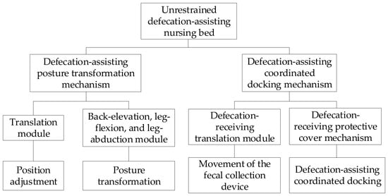
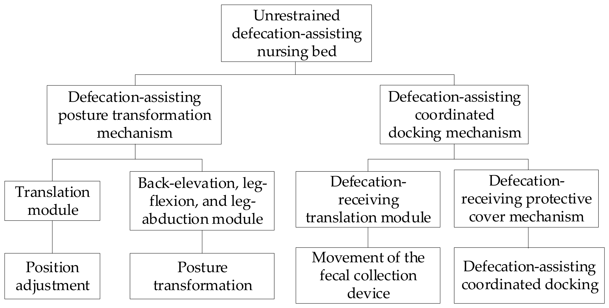
To address the aforementioned issues, this paper proposes a novel unrestrained defecation-assisting nursing bed, which comprises a defecation-assisting posture transformation mechanism and a defecation-assisting coordinated docking mechanism, as shown in Figure 1.
Figure 1.
The overall design of the defecation-assisting nursing bed.
With the aim of improving the safety, comfort, and nursing convenience of patients during bed-based defecation, a patient-positioning mechanism is designed to enable autonomous patient-positioning toward the defecation port. By optimizing the bed posture transformation mechanism, the pushing sensation on the back during posture adjustment is reduced, thereby enhancing the stability of patient repositioning. In addition, a variable-form keel-structure protective cover is designed to improve the fitting accuracy between the shield and the patient’s perineal region, thereby reducing the risk of excrement spillage and contamination.
The remainder of this paper is organized as follows. The working principle and design of the key mechanisms are discussed in Section 2. The control system and control methods for posture transformation and defecation docking mechanism are designed and researched in Section 3. Experiments related to device mobility capabilities are analyzed in Section 4. The conclusion and proposals for future work are given in Section 5.
2. Design of Key Mechanisms
2.1. Working Principle and Overall Structure
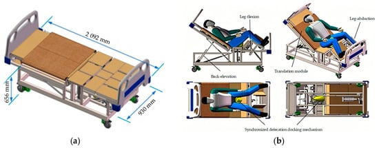
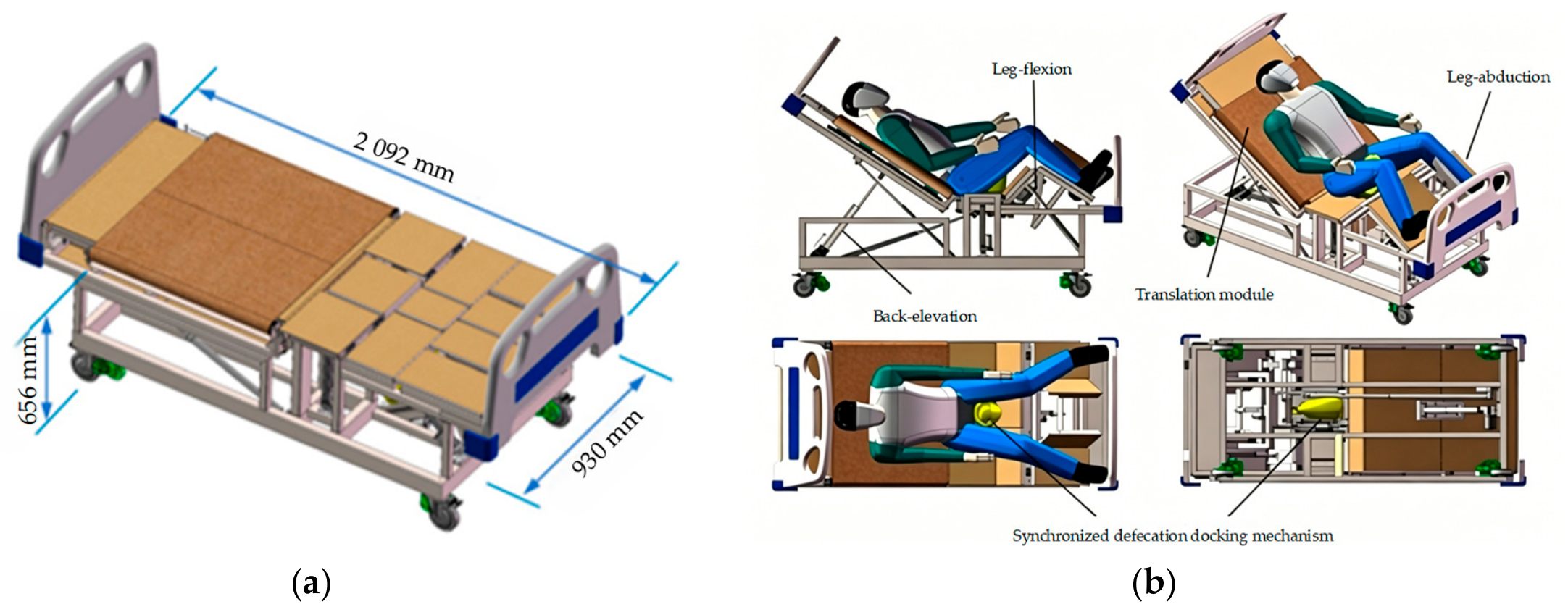
A schematic diagram of the overall structure of the unrestrained defecation-assisting nursing bed is shown in Figure 2. The defecation-assisting posture transformation mechanism consists of a translation module and a back-elevation, leg-flexion, and leg-abduction module. The translation module repositions the human body using a guide rail support system, motor actuation, and friction drive between the roller and the fabric. The back-elevation, leg-flexion, and leg-abduction module uses electric linear actuators as its primary power source. The extension and retraction of the actuators drive the corresponding bed panels to rotate about their pivot axes, thereby enabling human posture transformation. The defecation-assisting coordinated docking mechanism consists of a defecation-receiving translation module and a defecation-receiving protective cover mechanism. The defecation-receiving translation module adopts a solution combining an electric linear actuator with a scissor mechanism and a stepper motor with a lead screw mechanism to achieve vertical adjustment and horizontal adjustment of the defecation receiver, respectively. The defecation-assisting coordinated docking mechanism is designed by imitating the keel structure of a pangolin, and its motion control is realized through a control algorithm.
Figure 2.
A schematic diagram of the unrestrained defecation-assisting nursing bed. (a) Top view; (b) main modules.
2.2. Design of the Defecation-Assisting Posture Transformation Mechanism
The defecation-assisting posture transformation mechanism is mainly composed of two parts: the translation module and the back-elevation, leg-flexion, and leg-abduction module.
2.2.1. Design of the Translation Module Mechanism
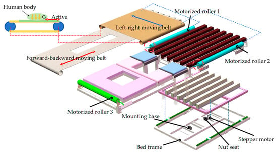
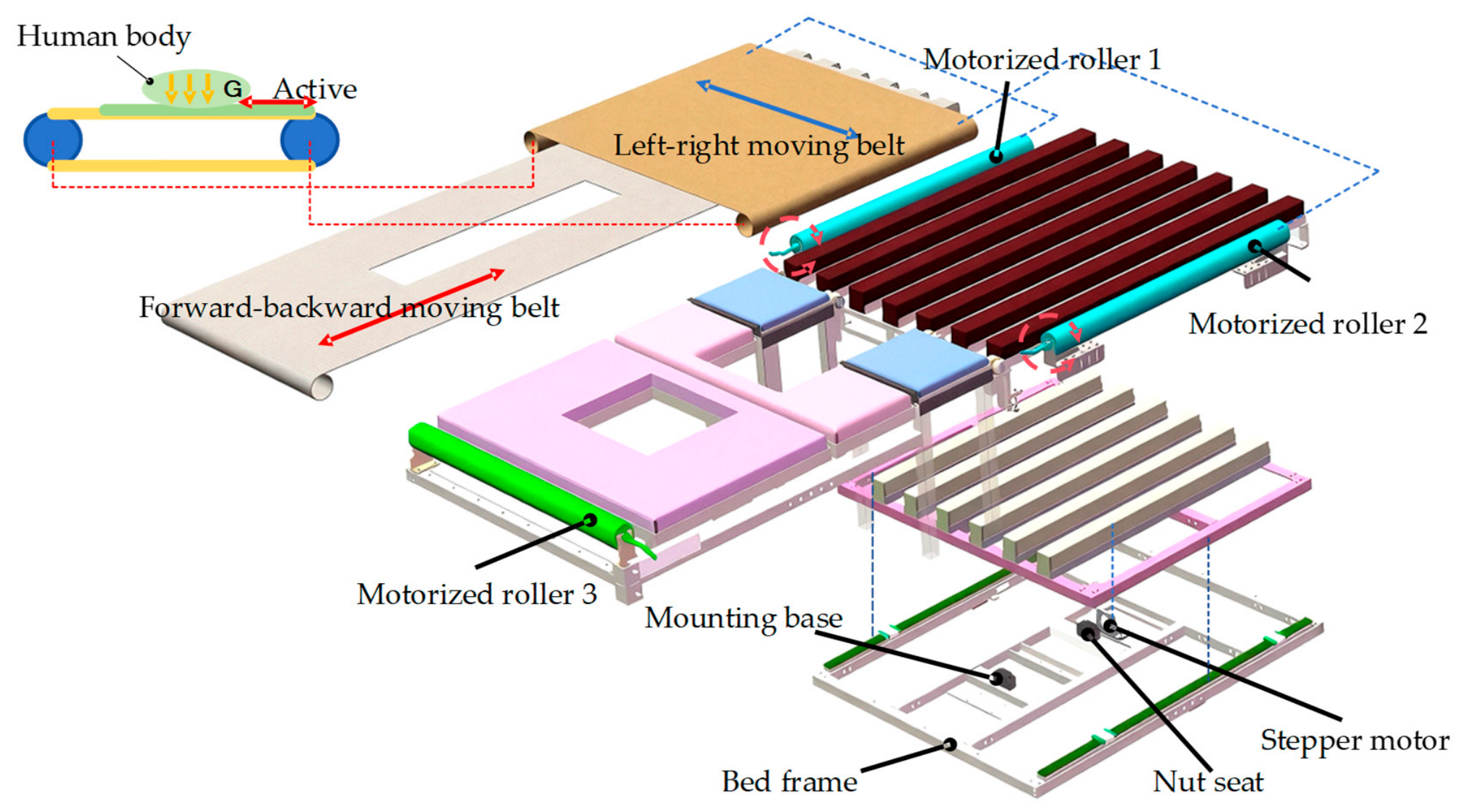
The translation module is primarily used to move the human body, enabling the patient to be accurately aligned with the defecation opening. Since most of the human body weight is concentrated above the hips, a crossed two-layer transmission structure is adopted in the back area. The left–right movement of the module is achieved through the coordinated active and passive cooperation between the upper lining cloth and two motorized rollers. The forward–backward movement is achieved through the coordination of the stepper motor, motorized rollers, and lower lining cloth, driving the crossed foam pad to move, thereby achieving overall human body displacement. To ensure smooth motion, the crossed foam pad for forward–backward movement is slightly lower than the crossed foam pad for left–right movement. The working principle of the translation module is shown in Figure 3.
Figure 3.
The working principle of the translation module.
The motorized roller is the core driving component of the translation module, and its driving capacity directly affects the stability and safety of the patient translation process. The original static model considers only the sliding friction at the contact interface between the bedsheet and the cross-shaped foam pad and is suitable for preliminary estimation under constant-speed motion, symmetric loading, and ideal transmission conditions. Taking the roller output shaft as the reference, the required static driving torque is given by:
where is the safety factor; is the equivalent coefficient of sliding friction at the contact interface between the bedsheet and the foam pad; is the patient mass; is the gravitational acceleration; and is the radius of the motorized roller.
However, during actual translation, additional factors must be considered, including the acceleration-induced inertia of the patient and moving components, the additional viscoelastic resistance caused by sustained compression of the cross-shaped foam pad, transmission losses in the fabric–roller wrap interface, and nonuniform distribution of the human body load. Therefore, based on the static model, the equivalent traction resistance of the translation module is expressed as:
where is the equivalent coefficient representing the additional resistance caused by viscoelastic deformation of the foam pad; is the equivalent mass of the bedsheet, foam pad, and flexible load-bearing components moving together with the patient; is the maximum design acceleration of the translation module; and is the additional no-load resistance generated by fabric pretension, the guide mechanism, and other external moving components.
Further accounting for asymmetric human body loading, the transmission efficiency of the roller–fabric wrapping interface, and the inertia of the rotating components, the required design torque at the roller output shaft is expressed as:
where is the correction factor for asymmetric human body loading; is the effective transmission efficiency of the fabric–roller wrapping interface; and is the equivalent rotational inertia referred to the roller shaft.
Based on the structural dimensions of the translation module, the operating speed of the selected motorized roller, and the worst-case asymmetric loading condition, the parameter values used for the driving-torque calculation are listed in Table 1.
Table 1.
Motorized roller driving-torque calculation parameters.
Taking a 100 kg patient as an example and using the parameter values in Table 1, Equation (2) gives =137.97 N. Substituting this value into Equation (3) yields = 8.43.
Meanwhile, to reduce the risks of localized fabric slackening, slippage, and accumulation under asymmetric human body loading, the translation module maintains adequate pretension and an effective wrap angle between the roller and the fabric, limits the acceleration during startup and braking, and ensures synchronous operation of the motorized rollers on both sides. These measures reduce localized fabric wrinkling and lateral deviation caused by differences in traction speed between the left and right sides. When a significant displacement difference between the two sides or an abnormal driving current is detected, the translation motion is stopped to prevent sustained fabric slippage or entanglement. These design measures ensure the driving stability of the translation module under actual asymmetric human body loading conditions.
2.2.2. Design of the Back-Elevation, Leg-Flexion, and Leg-Abduction Module Mechanism
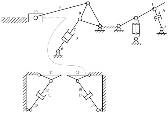
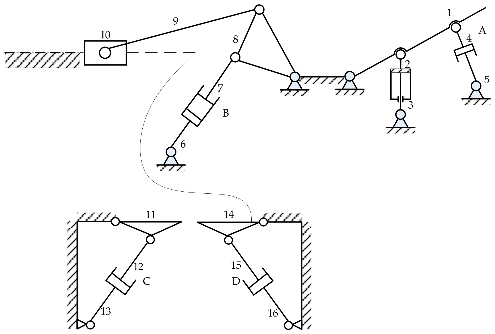
The back-elevation, leg-flexion, and leg-abduction module consists of a back-elevation and leg-flexion submechanism operating in the sagittal plane and left and right leg-abduction submechanisms. The back-elevation and leg-flexion motions occur in the longitudinal sagittal plane of the bed, whereas the left and right leg-abduction motions occur in planes orthogonal to it. Each leg-abduction submechanism uses the corresponding moving link of the leg-flexion mechanism as its local base, and its revolute joint forms an independent one-degree-of-freedom kinematic chain in a moving local coordinate system without imposing additional constraints on the upstream back-elevation or leg-flexion closed loops. Therefore, the overall mechanism is not treated as a single planar mechanism but is decomposed into several mutually independent planar submechanisms for degree-of-freedom analysis. The kinematic principle of the back-elevation, leg-flexion, and leg-abduction module is illustrated in Figure 4.
Figure 4.
A mechanism kinematic schematic diagram of the back-elevation, leg-flexion, and leg-abduction module. 1. The bed back plate; 2. the upper end of the gas spring; 3. the lower end of the gas spring; 4. the piston rod of electric linear actuator A; 5. the mounting base of electric linear actuator A; 6. the mounting base of electric linear actuator B; 7. the piston rod of electric linear actuator B; 8. the first leg-flexion plate; 9. the second leg-flexion plate; 10. the slider; 11. the first calf flip plate; 12. the piston rod of electric linear actuator C; 13. the mounting base of electric linear actuator C; 14. the second calf flip plate; 15. the piston rod of electric linear actuator D; 16. the mounting base of electric linear actuator D.
For any planar submechanism, its mobility can be calculated using the planar Kutzbach criterion:
where is the number of moving links in the -th submechanism; is the number of lower pairs; and is the number of higher pairs.
The calculations show that the back-elevation and leg-flexion submechanism has 2 degrees of freedom, while the left and right leg-abduction submechanisms each have 1 degree of freedom. Because the submechanisms are kinematically decoupled, the overall mechanism has 4 degrees of freedom.
Based on the mechanism schematic diagram and the degree-of-freedom calculation, it can be seen that the four electric linear actuators added between 4 and 5, 6 and 7, 12 and 13, and 15 and 16 drive the entire mechanism, and the mechanism has determinate motion.
2.2.3. Analysis of Human Back Slip During Posture Transformation
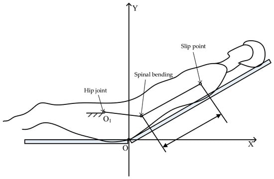
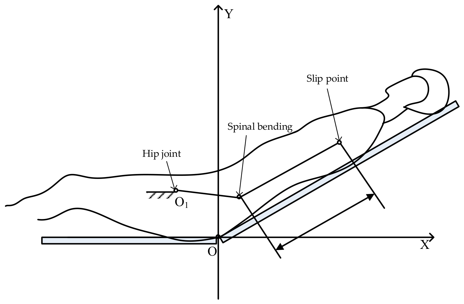
During the back-elevation process, the physiological center of rotation of the human body is the hip joint, which deviates from the mechanism center of rotation of the back plate in both the horizontal and vertical directions. This positional deviation causes a relative tangential displacement between the human back and the back plate along the plate surface. For disabled and partially disabled elderly patients, their core strength is insufficient to independently adjust their posture to counteract the slip, which significantly reduces their quality of rest.
To analyze the actual effect of slipping during the back-elevation process, a motion simulation model of the back-elevation process is established based on ergonomics. When the back plate is raised, the human body transitions from a supine posture to a sitting–reclining posture, accompanied by a certain bending deformation of the hip joints and spine. A schematic diagram of human body slipping motion during the back-elevation process is shown in Figure 5.
Figure 5.
A schematic diagram of the slipping motion.
Under ideal conditions, the back plate is elevated at a constant preset speed. To calculate the slipping displacement of the human body relative to the back plate during the back-elevation process, a simplified kinematic model was established in MATLAB/Simulink R2025b based on the relative motion between the human body and the back plate. The lifting angle, angular velocity, and lifting time of the back plate were used as model inputs. Based on the geometric relationship between the human back and the back plate, the model calculates the displacement of the human back relative to the back plate during elevation and outputs the variation curve of slipping displacement with time. The model describes the relative slipping process between the human body and the back plate under ideal conditions, without considering factors such as soft-tissue deformation, mattress compression, and variations in contact friction.
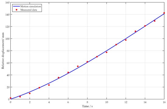
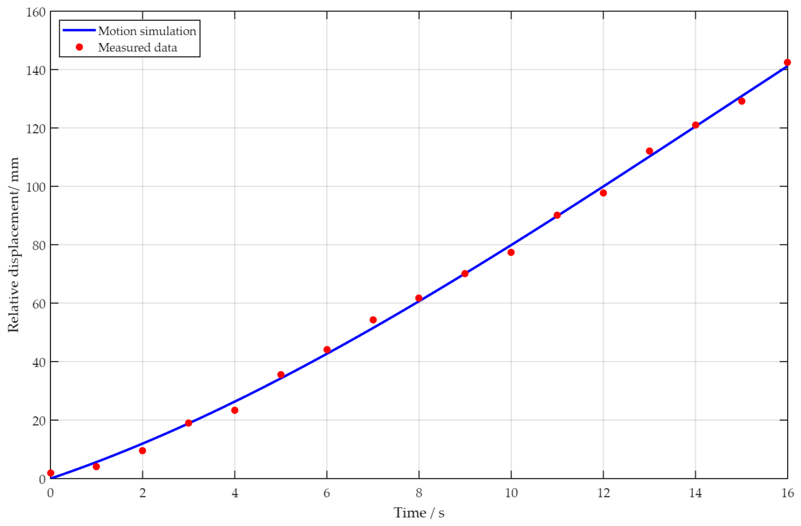
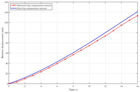
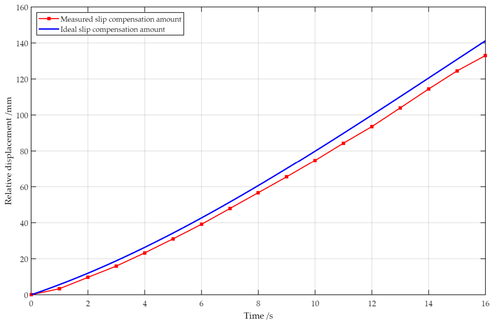
To verify the reliability of the simulation results, human-subject experiments were conducted to obtain the relative displacement data between the human body and the bed plate. A draw-wire displacement sensor was used as the measurement device and installed on the upper surface of the back plate near the pivot axis. The wire end of the sensor was connected to the contact region between the human back and the bed plate. During the back-elevation process, the sensor recorded the slipping displacement of the human back relative to the back plate. The data acquisition interval was set to 1 s, and the average of multiple measurements was used as the experimental result. As shown in Figure 6, the simulation curve and the measured data exhibit generally consistent variation trends, indicating that the established kinematic model can accurately describe the slipping displacement of the human body relative to the back plate during the back-elevation process.
Figure 6.
The variation curve of the slipping displacement.
To further quantitatively evaluate the predictive performance of the simulation model, the root mean square error (RMSE) and Pearson correlation coefficient were used to assess the agreement between the simulated results and the measured data. The RMSE is calculated as follows:
The Pearson correlation coefficient is calculated as follows:
where is the experimentally measured value at the -th sampling instant; is the corresponding simulated value at the same instant; and are the mean values of the experimental measurements and simulated results, respectively; and is the number of matched sampling points in the experimental and simulation datasets.
The results show that the root mean square error between the simulated and measured data was 2.08 mm, while the Pearson correlation coefficient was 0.9989. The small RMSE indicates only a minor absolute deviation between the simulated and experimentally measured values, whereas the Pearson correlation coefficient close to 1 demonstrates a strong agreement between the two datasets in terms of their variation trends.
It should be noted that, during the middle stage of the 16 s back-elevation cycle, particularly at approximately 8–9 s, a certain local discrepancy was observed between the measured data points and the smooth simulation curve, with a maximum deviation of approximately 2.8 mm. This discrepancy may be attributable to the compliance and viscoelasticity of human soft tissues. Under compressive and shear loading, the soft tissues of the back undergo localized compression, shear deformation, and a certain degree of response lag, causing the actual displacement of the human back to exhibit nonlinear and transient characteristics. In addition, the frictional condition at the contact interface between the patient’s clothing and the back plate may vary with changes in normal pressure, contact area, and relative motion, potentially resulting in localized stick–slip behavior.
Because the current simplified kinematic model does not account for factors such as human soft-tissue deformation, mattress compression, and dynamic variations in friction, the simulated curve is smoother than the measured data. Despite the aforementioned local discrepancies, the quantitative statistical results indicate that the model can adequately capture the overall pattern of relative slippage between the patient’s back and the back plate during the back-elevation process.
2.3. Design of the Defecation-Assisting Coordinated Docking Mechanism
The defecation-assisting coordinated docking mechanism is mainly composed of two parts: the defecation-receiving translation module and the defecation-receiving protective cover mechanism.
2.3.1. Design of the Defecation-Receiving Translation Module
The defecation-receiving translation module is used to collect the patient’s feces and achieve precise docking with the human body through the defecation-receiving shield. The defecation-receiving translation mechanism primarily provides lateral translation and vertical translation for the defecation-receiving mechanism. Lateral translation is used to move the defecation-receiving mechanism underneath the buttocks, and vertical translation is used to complete the docking between the defecation-receiving protective cover and the human body.
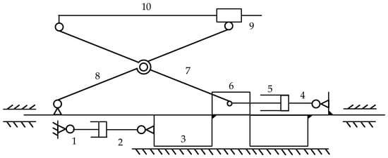
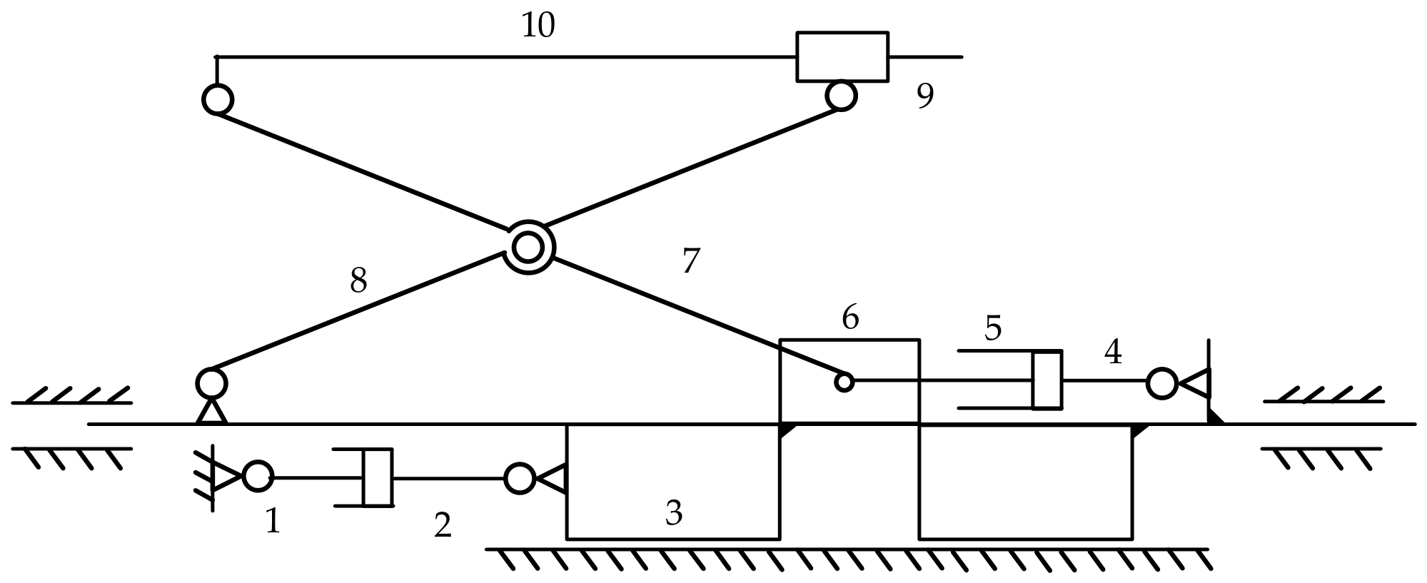
The kinematic schematic diagram of the defecation-receiving translation module mechanism is shown in Figure 7. According to this schematic diagram, its degree of freedom can be obtained as
Figure 7.
A kinematic schematic diagram of the defecation-receiving translation module mechanism. 1. The mounting base of electric linear actuator A; 2. the piston rod of electric linear actuator A; 3. a slider; 4. the mounting base of electric linear actuator B; 5. the extendable rod of electric linear actuator B; 6. a slider; 7. the first shear link; 8. the second shear link; 9. the defecation receiver bracket; 10. the defecation-receiving protective cover.
From the mechanism schematic diagram and degree-of-freedom calculation, it can be concluded that the two electric linear actuators installed between links 1 and 2 and between links 4 and 5 enable the whole mechanism to achieve determinate motion.
2.3.2. Structural Design of the Defecation-Receiving Protective Cover
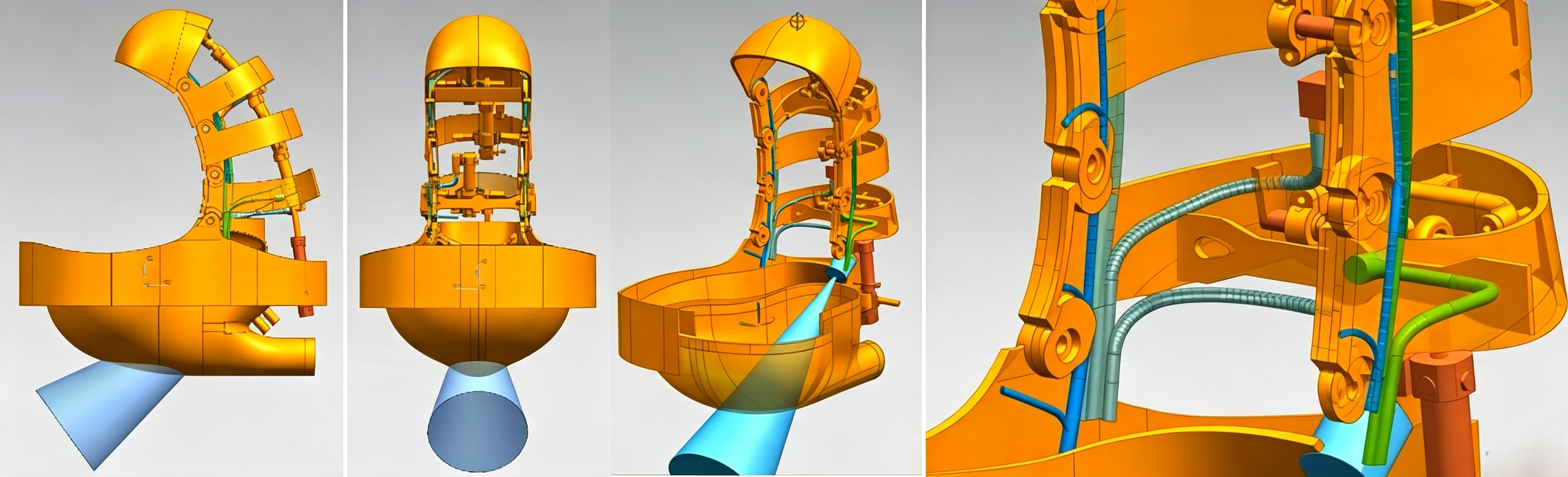
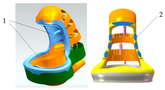
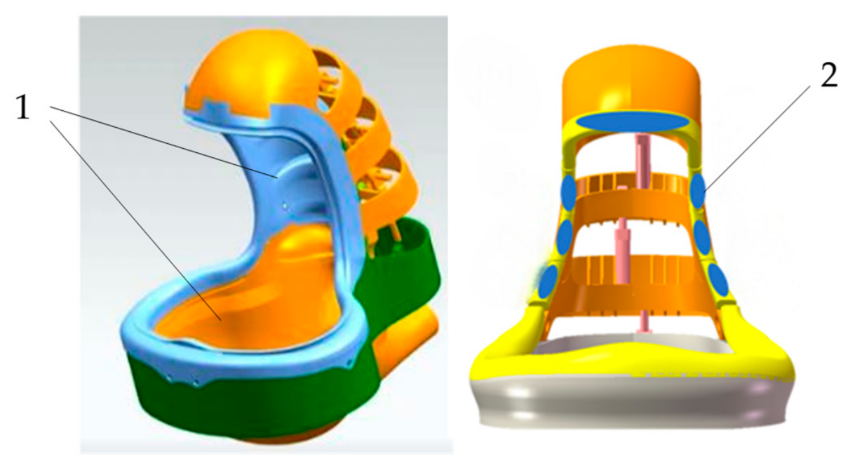
The defecation-receiving protective cover is designed by imitating the deformation of a pangolin, using flexible silicone material [30]. Seven flexible pressure sensors are installed at the contact area with the human body to accurately perceive the contact status between the shield and the human defecation site, thereby improving the sealing performance between the human body and the cover. The defecation-receiving protective cover consists of three components: a multi-joint keel frame, an inner-lining structure, and a flushing bedpan.
The multi-joint keel structure and the measuring range of the corresponding sensor are shown in Figure 8. Miniature electric linear actuators are embedded inside this structure and connected end to end in series to drive the bending deformation of the keel frame. Electrical circuits, water passages and air passages are laid out on the inner side of the keel. A laser sensor is mounted beneath the keel, whose measuring range covers the excrement position to identify defecation states.
Figure 8.
The multi-joint keel structure of the defecation-receiving protective cover and sensor measurement range.
The inner-lining structure of the defecation-receiving protective cover is shown in Figure 9. The lining is fabricated from heterogeneous silicone material to improve safety for bedridden elderly users during coordinated docking for defecation. Seven RP-C7.6-LT flexible resistive pressure sensors are embedded in the lining. Each sensor has a force-sensing range of 30 g–1.5 kg, a response time of less than 10 ms, and can detect dynamic loads at frequencies up to 10 Hz. A high-precision human–machine contact-force sensing system was established to accurately detect the contact state between the human body and the defecation-receiving protective cover.
Figure 9.
A schematic diagram of the inner-lining structure. 1. The inner lining; 2. the flexible pressure sensor.
The heterogeneous silicone material is primarily used to form the flexible inner lining of the defecation-receiving protective cover, thereby improving conformity and safety during contact with the human body. The lining undergoes passive deformation in response to the motion of the internal keel structure. The overall geometric configuration of the cover is mainly determined by the internal four-segment keel frame and the linear actuation mechanism. Therefore, the subsequent kinematic analysis adopts a segmented rigid-body approximation, while the effects of compliant deformation of the silicone lining are treated as non-ideal positioning errors in the actual system.
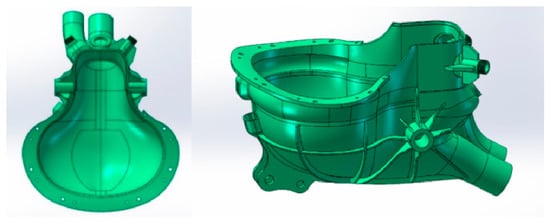
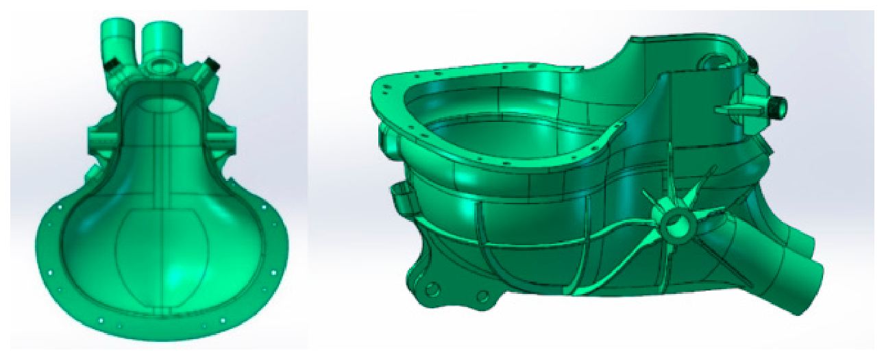
The three-dimensional structure of the flushing bedpan is shown in Figure 10. The shape of the flushing bed pan fully considers the connection with the pipelines, achieving efficient adaptation to the defecation-assisting posture transformation module and post-defecation cleaning care. Three nozzles are installed inside to improve flushing quality and enhance gender inclusivity for both male and female users.
Figure 10.
The three-dimensional structure of the flushing bedpan.
To preliminarily verify the flushing performance of the three-nozzle configuration, a fluid model of the flushing bedpan was further established in ANSYS Fluent 2024 R1, and the flushing process was analyzed using a transient water–air two-phase flow model. The results show that the water jets generated by the three nozzles can be directed toward the primary cleaning areas as intended, thereby satisfying the operational requirements.
2.3.3. Workspace of the Defecation-Receiving Protective Cover
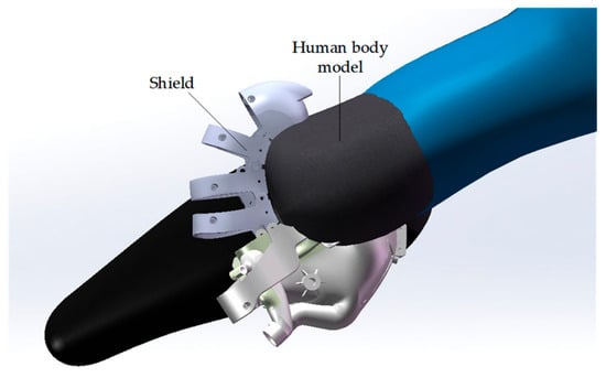
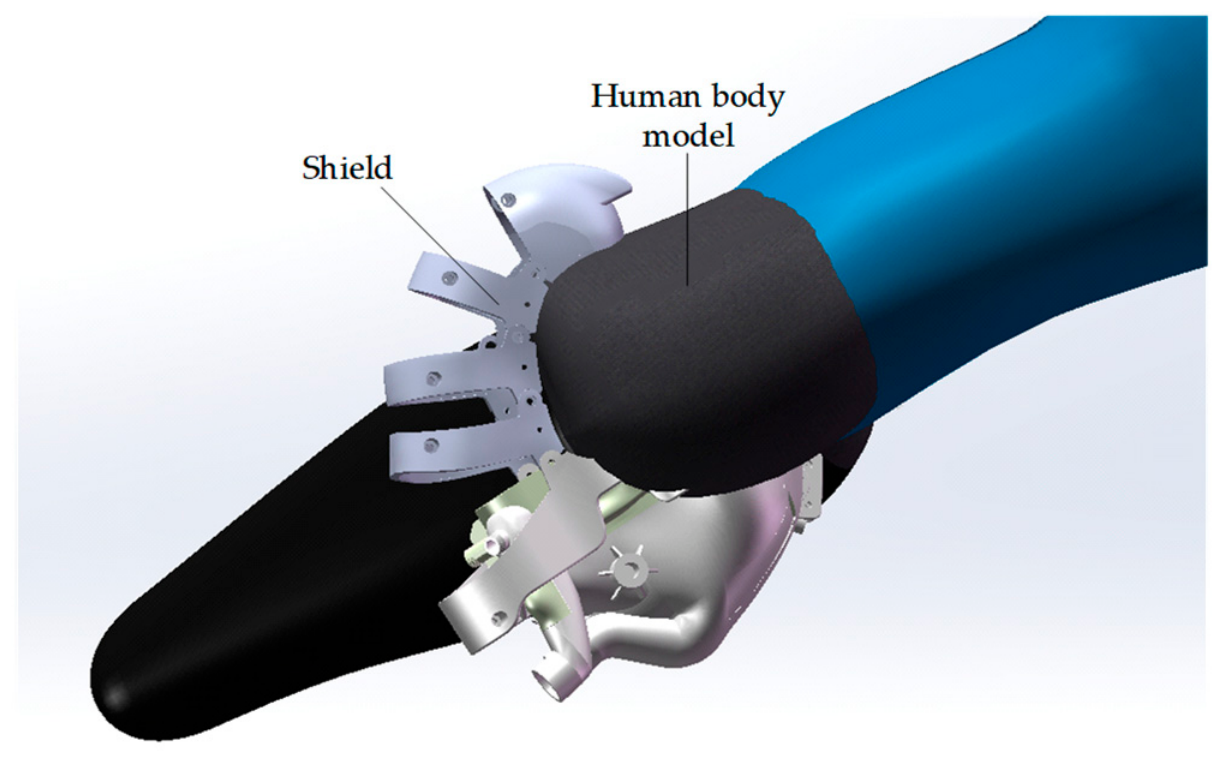
The working posture of the cover is shown in Figure 11. The defecation-receiving protective cover must maintain full contact with the human defecation and urination areas to ensure that waste residues do not splash or leak. Therefore, the motion workspace of the defecation-receiving protective cover is a core performance indicator.
Figure 11.
The working posture of the cover.
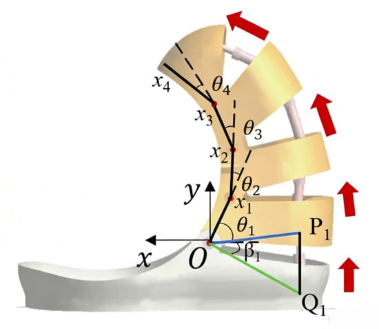
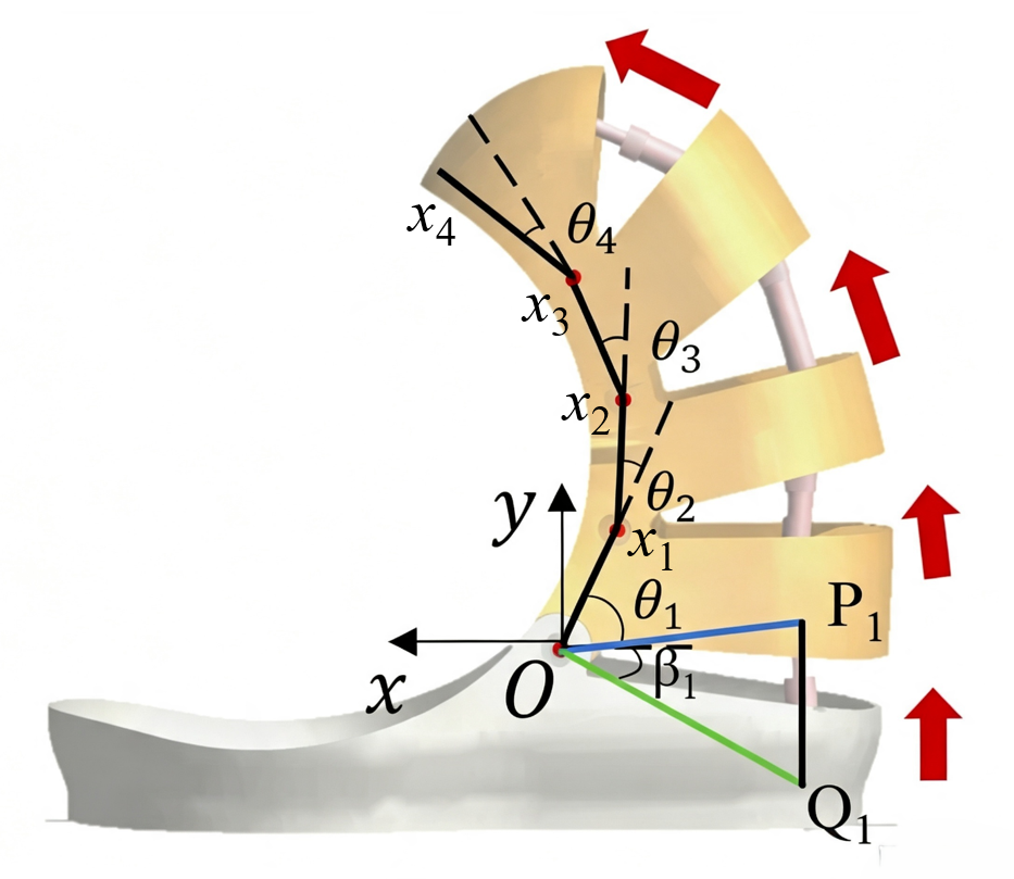
Taking the joint between the cover base and the first keel segment as the coordinate origin, a fixed global coordinate system is constructed. Meanwhile, individual relative coordinate systems for motion analysis are established with the endpoint of each corresponding keel segment of the cover as their respective origins. The coordinate arrangement is shown in Figure 12.
Figure 12.
The coordinate system of the cover. The red arrows in the figure indicate the movement directions of the cover at the start of motion.
In Figure 12, is the fixed coordinate system. The connection between the starting point and the end position of each keel segment is simplified as a connecting rod, with lengths l1, l2, l3, and l4 respectively. The angle between the first keel segment connecting rod and the negative direction of the axis is . The angle between the second keel segment connecting rod and the extension line of the first keel segment connecting rod is . Similarly, angles and are selected. Thus, the angular displacements of each keel segment are respectively. Based on the established coordinate system, the relationship between the end position of each keel segment of the cover and the angular displacement is derived as:
where ; ; ; .
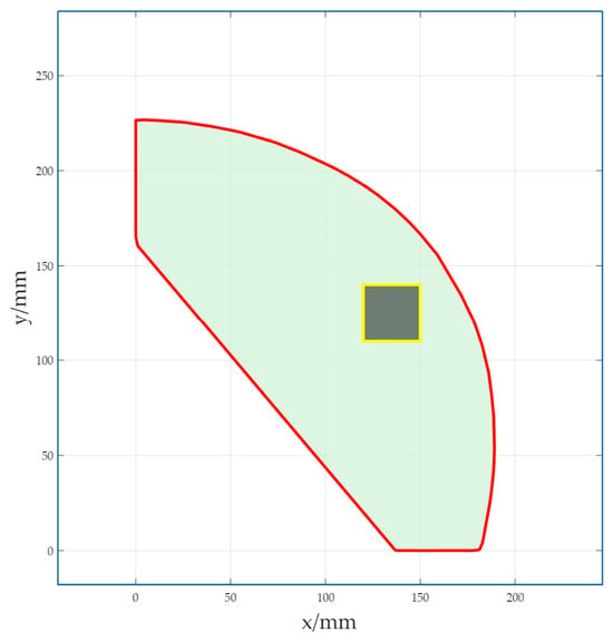
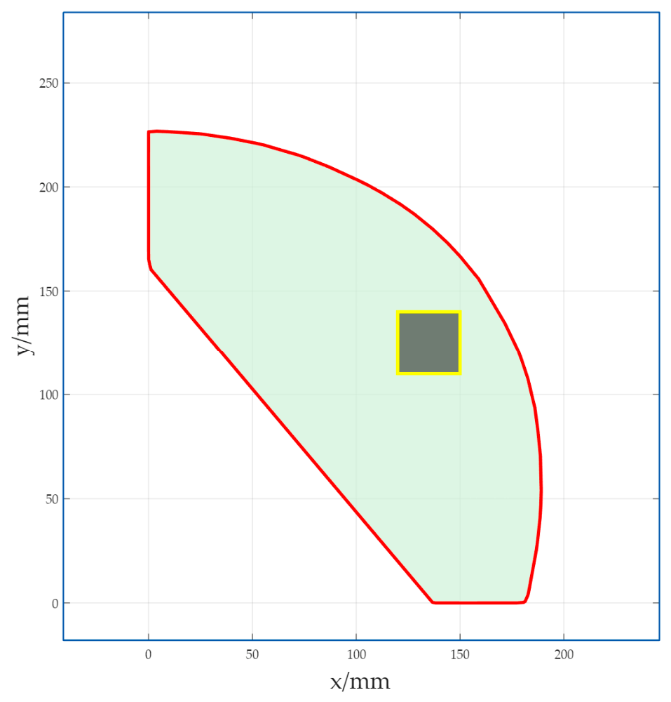
In the MATLAB software, the Monte Carlo method was used to solve the workspace of the cover and generate a contour plot, with the results shown as the red area in Figure 13. According to GB/T 10000-2023 “Human Dimensions of Chinese Adults” [31], combined with the actual working posture of the cover and the established coordinate system, it can be determined that the range for the human body in the x-axis direction is 120–150 mm, and in the y-axis direction is 110–140 mm. The determined range is shown as the yellow area in Figure 13. It can be seen from the figure that the theoretical motion workspace of the cover completely covers the target workspace required by the human body, thereby meeting the usage requirements.
Figure 13.
The workspace of the cover.
The upper and lower hinge points of the -th electric linear actuator are mounted on two adjacent keel segments, respectively. Therefore, the angle , formed by the upper and lower hinge points of the linear actuator and the joint rotation center, varies with the corresponding angular displacement . Let the local position vectors from the joint rotation center to the lower and upper hinge points of the linear actuator be and , respectively, with magnitudes and . According to the relative rotational relationship between the adjacent keel segments, the following expression can be obtained:
where is a two-dimensional rotation matrix. Since the mounting positions of the linear actuator hinge points on the keel segments are fixed, there is a deterministic mapping relationship between and . Therefore, the length of the -th electric linear actuator can be expressed as a function of the angle :
For each valid combination of angular displacements generated using the Monte Carlo method, the end position of the cover and the corresponding lengths of the four linear actuators are calculated. The maximum and minimum lengths of each linear actuator over all valid configurations are then identified, thereby determining the actuator strokes required to cover the theoretical workspace:
The calculated theoretical strokes required for the four linear actuators are 34 mm, 19 mm, 38 mm, and 40 mm, respectively. The remaining parameters are listed in Table 2.
Table 2.
Keel segment data.
3. Control of Defecation-Assisting Posture Transformation
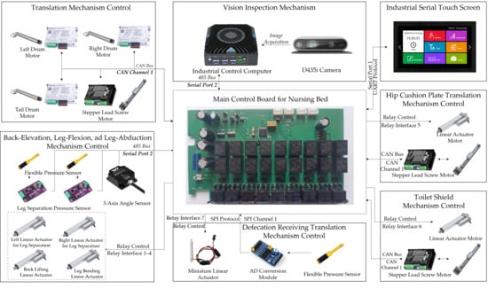
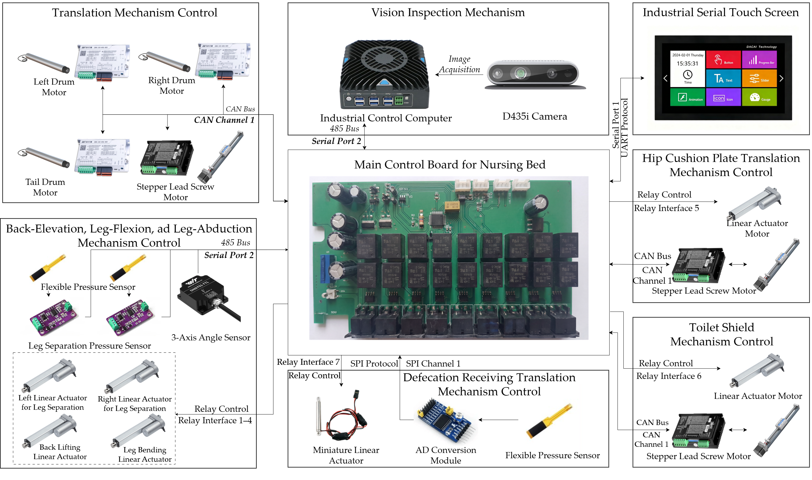
The control system of the defecation-assisting posture transformation mechanism includes 10 electric linear actuators, three stepper motors, three drum motors, nine flexible pressure sensors, one angle sensor, one vision sensor, as well as an industrial computer and a touchscreen [32]. The control system diagram is shown in Figure 14.
Figure 14.
A control system diagram of the defecation-assisting posture transformation mechanism.
The specific working process is as follows: The controller determines the position of the patient’s buttocks based on the information from the vision sensor. Through the coordinated operation of the three electric rollers and one stepper motor in the translation module, the patient’s left–right and forward–backward translation is achieved. After the patient’s buttocks reach the designated position, the four electric linear actuators in the back-elevation, leg-flexion, and leg-abduction module work together to place the patient in a defecation posture. Meanwhile, the flap force at the calf area is monitored in real time by two pressure sensors to ensure patient safety. Subsequently, the lower defecation opening is opened, and the defecation-receiving module is raised to the designated position of the patient. Based on the feedback information from the seven flexible pressure sensors, the four miniature electric linear actuators of the defecation-receiving protective cover are adjusted in real time, so that the patient’s excretion area is in close contact with the defecation-receiving protective cover, thereby completing the defecation process.
3.1. Motion Control of Translation Module
The coordinates of the patient’s buttocks center point are obtained in real time through the vision sensor. The calculation formula is:
where ; are the physical coordinates of the image; K is the camera matrix, and its expression is:
where are the focal lengths of the camera in pixel coordinates; and are the coordinates of the optical center on the image.
Similarly, the coordinates of the center point of the defecation-receiving module can be obtained, and through coordinate calculation, the movement distance d of the translation module can be obtained as:
The linear velocity of the translation module is achieved through the coordinated motion of two rollers, and the linear velocity of the rollers can be calculated according to the following formula:
where is the diameter of the roller; is the single-side thickness of the bedsheet on the roller; is the rotation speed of the roller motor; and is the reduction ratio of the roller motor.
By controlling the motor movement of the translation module, the patient can be accurately moved to the target position.
3.2. Motion Control of the Defecation-Receiving Protective Cover
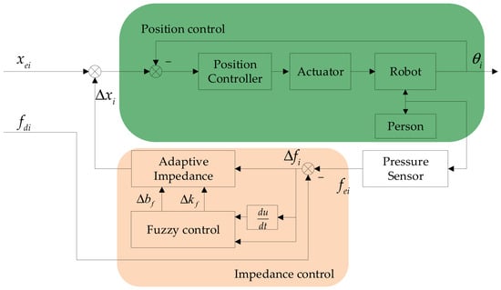
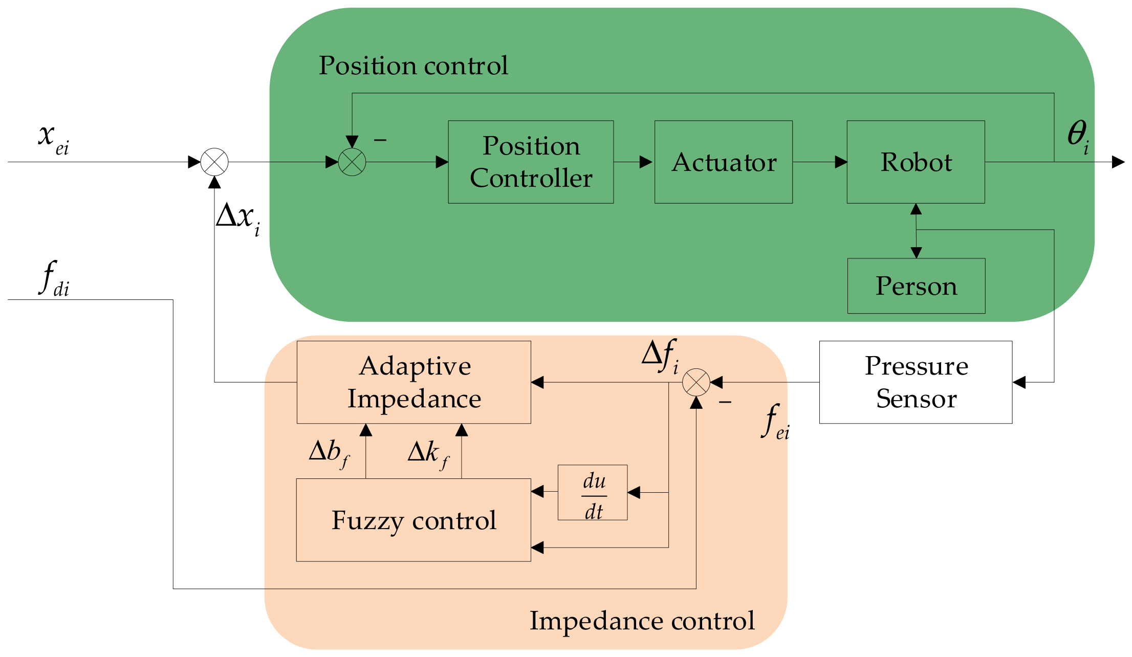
To ensure stable contact between the defecation-receiving shield and the human body without being affected by individual differences, fuzzy adaptive control is adopted for the motion control of the defecation-receiving protective cover. The schematic diagram of the fuzzy adaptive control is shown in Figure 15.
Figure 15.
A block diagram of the fuzzy adaptive control for the defecation-receiving protective cover. denotes the index of the keel segment; denotes the reference trajectory of the keel segment; denotes the corrected trajectory determined from the contact-force error; denotes the desired contact force of the keel segment in close conformity with the human body; denotes the actual contact force of the keel segment in close conformity with the human body; denotes the error between the actual and desired contact forces; denotes the actual angle of the keel segment; and and denote the damping and stiffness compensation outputs of the fuzzy controller, respectively.
To distinguish among the three control states of cover contact detection, stable conformity, and overload protection, the contact-detection threshold , desired contact force , and maximum allowable contact force are defined, respectively, subject to . The contact-detection threshold is determined according to the resolution, zero drift, and no-load noise of the flexible pressure sensor. The contact-detection thresholds for the first to fourth keel segments are set to 0.5 N, 0.4 N, 0.3 N, and 0.5 N, respectively. When the actual contact force remains above the corresponding threshold for 0.15 s, the system determines that the keel segment has established contact with the human body and switches from the position control mode to the fuzzy adaptive impedance control mode.
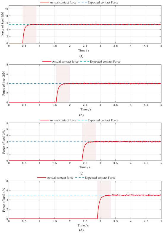
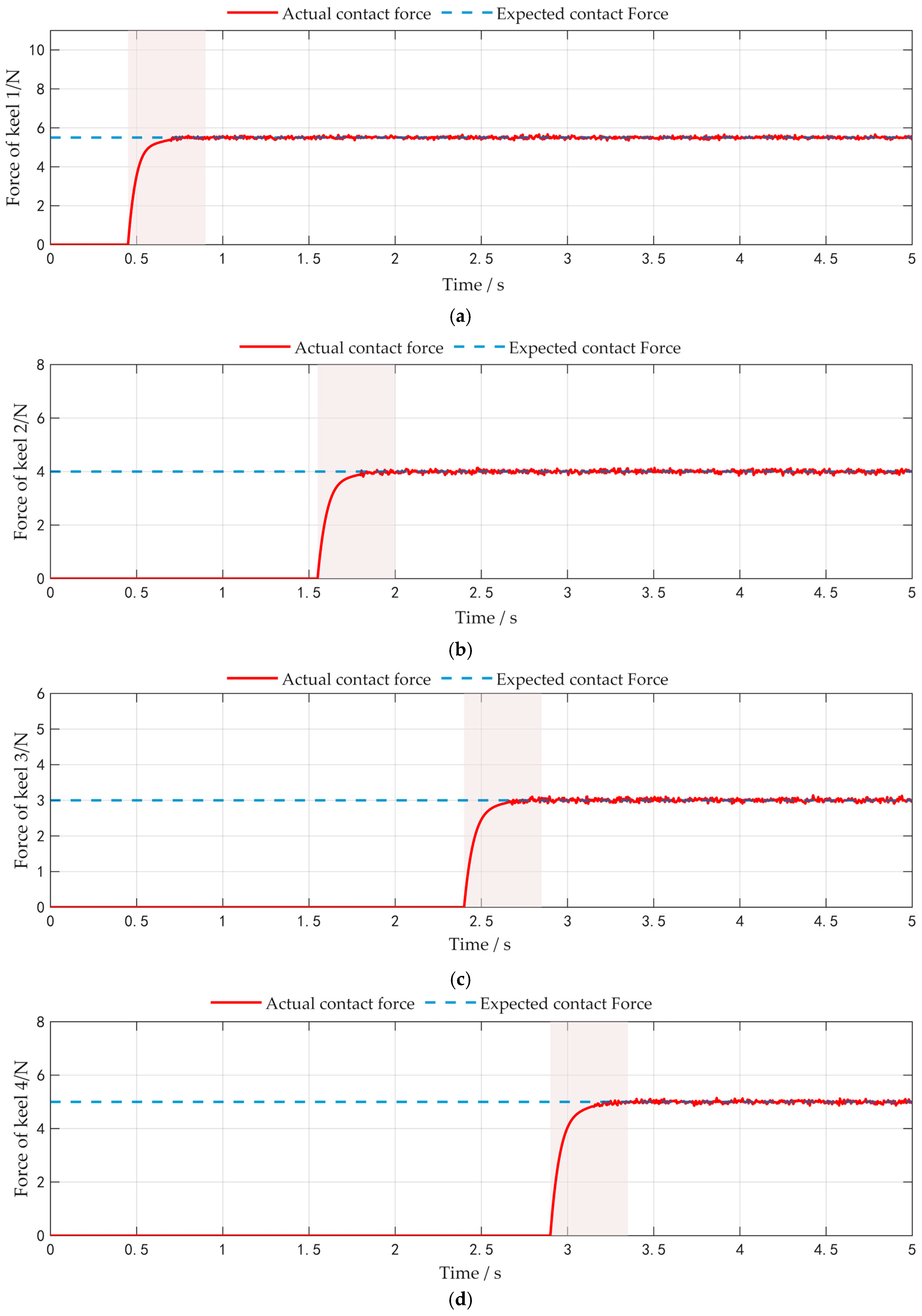
The desired contact force is determined by comprehensively considering the minimum force required for the cover to maintain stable conformity, the resolution and zero-point fluctuation of the flexible pressure sensor, the effective contact area, the contact stability and comfort evaluations obtained from preliminary experiments, and skin-pressure safety requirements. Because pressure injury depends not only on pressure magnitude but also on loading duration, shear force, skin moisture, and individual tissue tolerance, no uniform safe-pressure threshold is currently applicable to all body regions and operating conditions. The desired contact forces for the first to fourth keel segments were ultimately set to 5.5 N, 4.0 N, 3.0 N, and 5.0 N, respectively. Considering force-tracking overshoot, variations in the human body surface, and motion disturbances, the maximum allowable contact forces for the four keel segments were set to 7.0 N, 5.0 N, 4.0 N, and 6.5 N, respectively. These values are used only as engineering control ranges for experimental validation and should not be interpreted as absolute physiological safety thresholds applicable to all patients.
As shown in Figure 15, the impedance controller consists of an adaptive impedance module and a fuzzy controller. The actual contact force , measured by the pressure sensor, is compared with the desired contact force , and the force-tracking error is defined as:
To convert the force-tracking error into a compliant position correction, the dynamic transfer function is defined as:
where and are the Laplace transforms of the position correction and force error , respectively; is the inertia parameter; and and are the initial damping coefficient and initial stiffness coefficient, respectively.
The initial control equation can be derived from Equation (16) as follows:
To ensure zero steady-state force-tracking error, adaptive impedance parameters are introduced to compensate for the time-varying error. Meanwhile, system stability is taken into consideration when adjusting the adaptive impedance parameters. By applying the compensation terms and , the updated control equation is obtained as follows:
To further improve compliance and robustness during the contact process, a fuzzy controller is introduced to provide incremental compensation for the adaptive outputs. The inputs to the fuzzy controller are:
Before fuzzification, the two input variables are normalized using the scaling factors and , respectively:
where and denote the normalized contact-force error and the normalized rate of change of the error, respectively. The universes of discourse for both input variables are set to ([−1, 1]) and divided into seven fuzzy linguistic sets:
where NB, NM, NS, ZO, PS, PM, and PB denote negative big, negative medium, negative small, zero, positive small, positive medium, and positive big, respectively. Trapezoidal membership functions are used for NB and PB at the two ends of the universe of discourse, while triangular membership functions are used for the remaining fuzzy sets.
The outputs of the fuzzy controller are the damping compensation (a) and stiffness compensation . The general form of the ,-th fuzzy rule is given by:
where and are the input fuzzy sets; and are the output fuzzy sets corresponding to the damping and stiffness compensation terms, respectively; and , = 1, 2, …, 7. The two input variables constitute a total of fuzzy rules.
where and denote the membership degrees of the two input variables in their corresponding fuzzy sets, respectively.
After Mamdani fuzzy inference is completed, defuzzification is performed using the center-of-gravity weighted-average method. The damping and stiffness compensation terms are given by, respectively:
where and are the center values of the output fuzzy sets for the damping and stiffness compensation terms corresponding to the ,-th rule, respectively, and is the activation strength of the , q-th fuzzy rule. In this study, the output membership functions are symmetric fuzzy sets with identical shapes and areas. Therefore, the center values of the output fuzzy sets can be weighted by the activation strengths of the corresponding rules.
The final stiffness and damping coefficients are obtained by superposition as follows:
Thus, the final fuzzy adaptive impedance control equation is obtained as follows:
Equation (28) represents a manually specified target force–displacement dynamic relationship. This relationship converts the contact-force error into a smooth position correction, causing the keel segment to gradually move toward the human body when the contact force is insufficient and to gradually retract when the contact force is excessive.
4. Experimental Verification and Analysis
4.1. Experimental Design
The experimental objectives are as follows: (1) verify the docking accuracy of the translation module; (2) verify the functionality of the posture transformation mechanism; (3) verify the actual compensation effect of back plate slippage; (4) verify the variation in the working trajectory of the posture transformation mechanism; and (5) verify the feasibility of the control algorithm for the defecation-receiving protective cover.
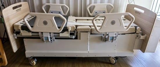
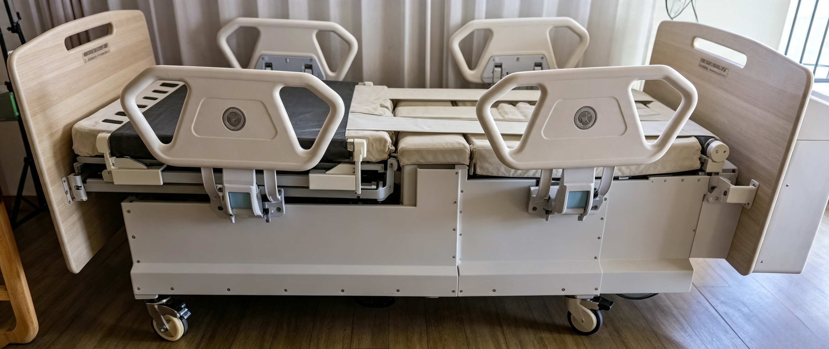
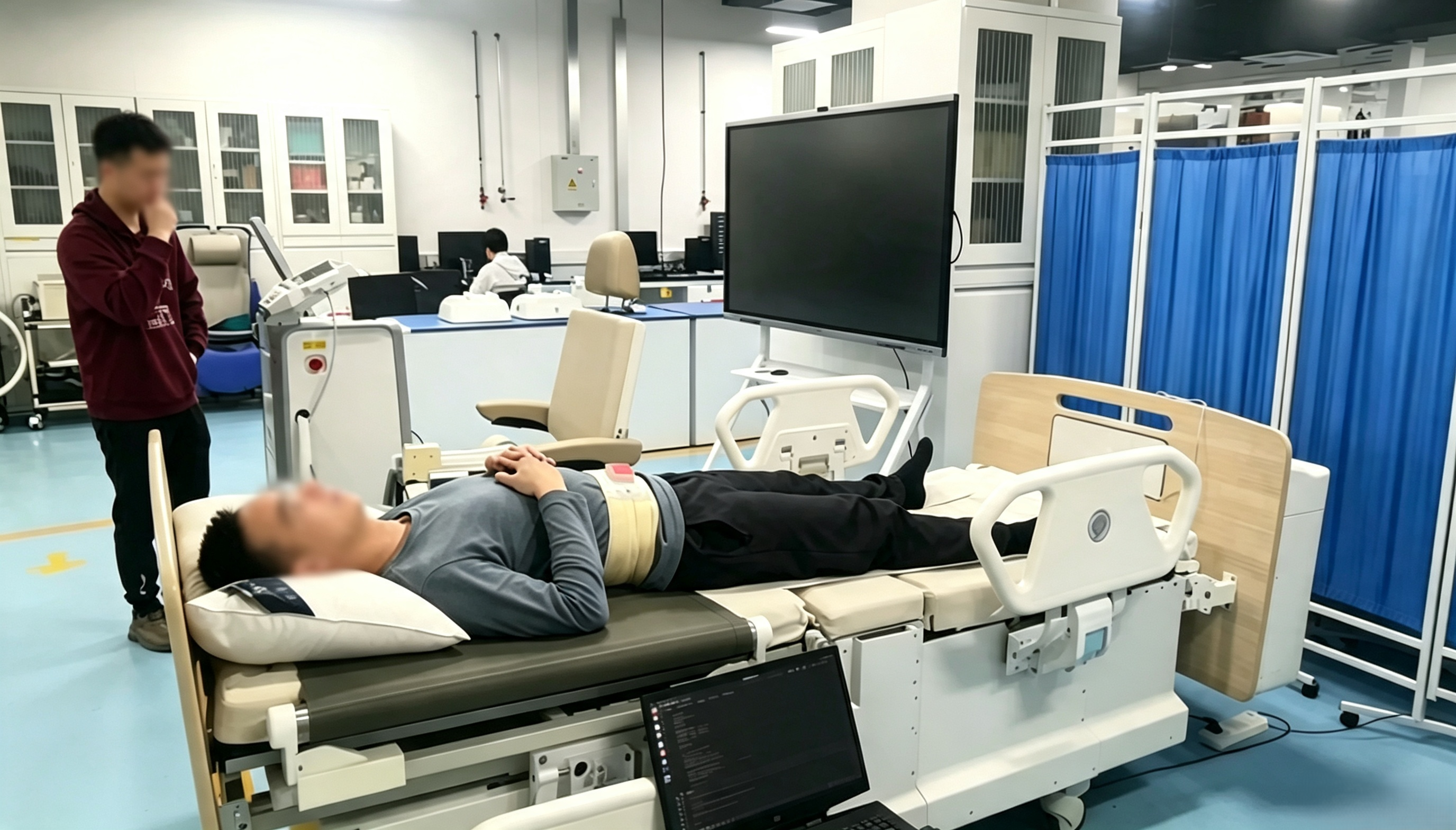
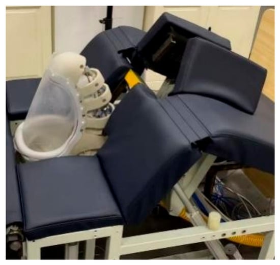
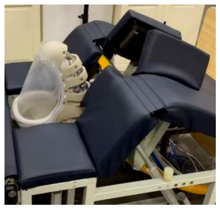
The experimental device includes a nursing bed prototype, healthy subjects, and a nine-axis digital inclinometer. The defecation-assisting posture transformation nursing bed prototype is shown in Figure 16. The specific characteristics of the subjects are presented in Table 3. Healthy subjects were recruited for the preliminary experimental verification. The purpose of this stage was to evaluate the basic functionality, operational feasibility, and initial pressure-regulation performance of the device under controlled conditions. However, healthy subjects do not fully represent the intended users, namely bedridden, disabled, or semi-disabled older adults. Frail older adults may differ from healthy individuals in body contour, soft-tissue compliance, and tolerance to contact pressure, which may result in different pressure distributions and comfort responses. Therefore, the present results should be regarded as preliminary validation under healthy-subject conditions, and further studies involving bedridden and functionally impaired older adults are required to confirm the applicability of the device to the target population.
Figure 16.
Defecation-assisting posture transformation nursing bed prototype.
Table 3.
The specific characteristics of the subjects.
In the posture transformation experiment, the operator operated the prototype to obtain data, and the data were recorded and analyzed; in the cover motion control experiment, data on the contact force between the shield and the human body were recorded and analyzed.
4.2. Experimental Results and Analysis of the Defecation-Assisting Posture Transformation Mechanism
4.2.1. Vision-Based Translation Positioning Accuracy and Repeatability Experiment
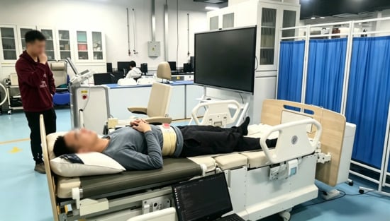
To verify the accuracy and repeatability of position adjustment by the translation module under visual positioning control, 20 repeated positioning trials were conducted. The vision sensor was mounted on the ceiling above the nursing bed, providing a top-down view covering the motion range of the translation module. The visual target was a standard red square marker attached to the defecation- and urination-intention detection device. Because the marker moves synchronously with the patient and the translation module, variations in subject body size do not affect the color or geometric characteristics of the visual target. The experimental setup is shown in Figure 17.
Figure 17.
Translation positioning accuracy test.
Before each trial, the subject was placed at an initial position with a different offset from the target position of the excretion opening. The vision system detected the position of the red square marker in real time and calculated its deviation from the target position, based on which the translation module was controlled to move. Once the marker reached the preset target position, the final coordinates were recorded. After each trial, the initial position was reset, and the test was repeated 20 times.
The results of the 20 repeated trials are presented in Table 4. The final positioning errors ranged from 1.41 to 7.21 mm, with a mean positioning error of 3.94 mm and a standard deviation of 1.72 mm. The maximum and minimum positioning errors were 7.21 and 1.41 mm, respectively. In all 20 trials, the final positioning error remained below 7.6 mm, with relatively small variation among trials, indicating that the proposed vision-based positioning control method provides good positioning accuracy, repeatability, and stability.
Table 4.
Positioning accuracy experimental data.
4.2.2. Functional Study of the Defecation-Assisting Posture Transformation Mechanism
The functional verification of the mechanism adopts “complete execution of functions, smooth operational logic, and safe and stable operation” as the core evaluation criteria. In accordance with its core functional positioning of assisting defecation, item-by-item testing was carried out for each functional module. The tests primarily examined whether the back-elevation, leg-abduction, leg-flexion, and coordinated motion functions of the device could be completed as designed during the defecation-assisting posture transformation process. Additionally, the operational stability, positioning accuracy of each motion, and repeat operation reliability were evaluated.
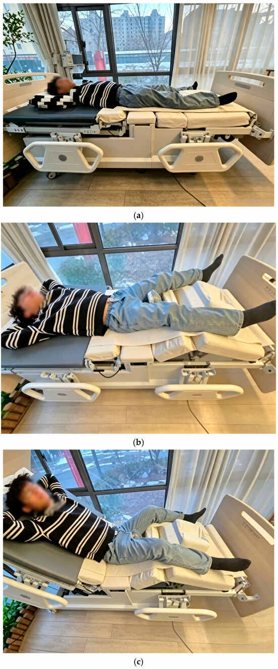
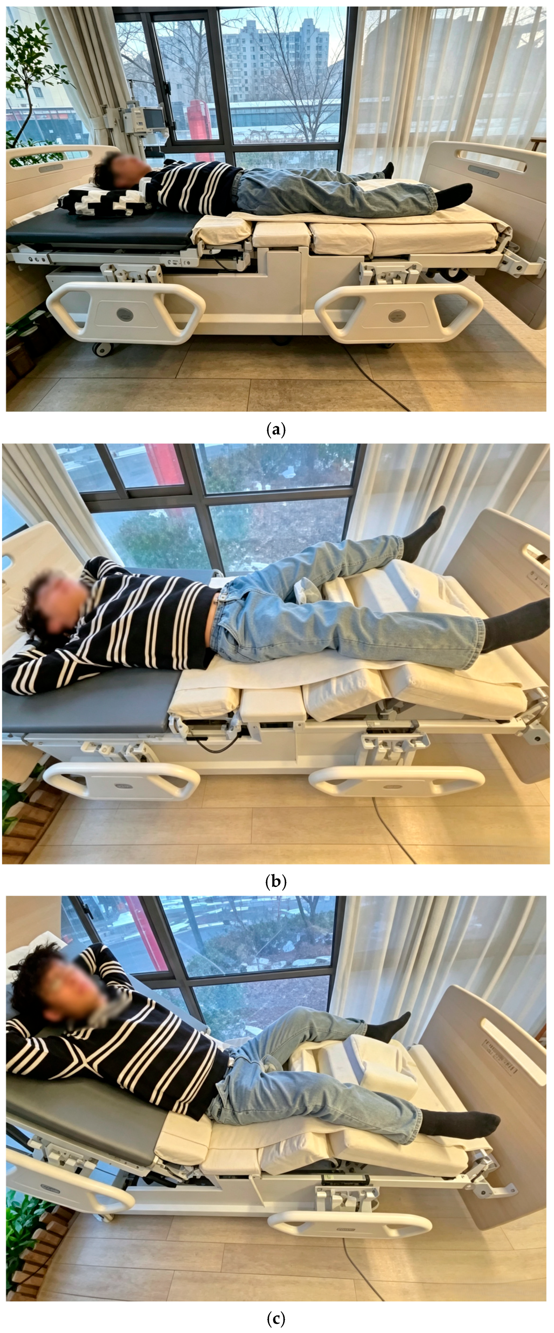
During the test, the mechanism was controlled by the experimenter using a remote controller. The mechanism sequentially completed the back-elevation, leg-abduction, leg-flexion, and reset actions. For each set of trials, the motion completion time, final positioning angle, operating status, and whether any abnormal conditions such as jamming, vibration, or abnormal noise occurred were recorded. To ensure the stability of the test results, each function was repeatedly tested several times. The motion process of the mechanism is shown in Figure 18.
Figure 18.
The motion process of the defecation-assisting posture transformation mechanism. (a) Leg-abduction process; (b) leg-flexion process; (c) back-elevation process.
The test data were compared and analyzed against the design targets to evaluate whether the back-elevation angle, leg-flexion angle, and leg-abduction angle met the design requirements. The specific data are presented in Table 5.
Table 5.
The functional test results of the nursing bed.
4.2.3. Research on Back Plate Slipping Compensation
This paper adopts a motorized roller-conveyor-belt-type follow-up compensation scheme. A movable conveyor belt is installed on the surface of the back-elevation backrest panel, and it is driven smoothly by a motorized roller. During the back-elevation process, the user’s back tends to slide downward along the backrest panel. The upper surface of the conveyor belt moves synchronously in the same direction as the back’s sliding motion—i.e., from the shoulder-end toward the buttock-end—so that the user’s back remains approximately stationary relative to the belt surface. This method converts the relative slip between the user’s back and the fixed backrest into an active motion of the belt relative to the backrest, thereby reducing back friction shear and clothing wrinkling, and improving back-elevation comfort.
To evaluate the effectiveness of this device, we followed the same method as the aforementioned real-person measurement experiment and compared the actual compensation values obtained with the theoretical data. The comparison results are shown in Figure 19.
Figure 19.
Comparison chart of slip compensation effects.
4.2.4. Research on the Working Trajectory of the Defecation-Assisting Posture Transformation Mechanism
The primary function of the defecation-assisting posture transformation mechanism is to gradually transition the nursing bed from a flat lying state to a posture suitable for elderly individuals to defecate while in bed. This transformation is accomplished through the coordinated operation of the back-elevation mechanism, leg-flexion mechanism, and leg-abduction mechanism, rather than through the independent movement of a single component. During the transformation process, two requirements must be met: first, the human body posture should approximate a natural sitting position, ensuring that the hip and knee joints of the elderly person remain comfortably bent; second, the trajectories of all moving components must be continuous and smooth, avoiding sudden posture changes that could cause body slippage or joint discomfort. Therefore, the study on the trajectory of the defecation-assisting posture transformation mechanism should focus on analyzing the motion sequence, angle variations, and key-point trajectories of the three modules: back elevation, leg flexion, and leg abduction.
During the process of defecating in bed, the most comfortable human posture should approximate the sitting posture for defecation, that is, with the upper body elevated, the hips flexed, the knees bent, and the legs moderately abducted. Based on the study of the physiological characteristics of disabled elderly individuals, the core parameters for the optimal comfortable defecation posture are determined [8,33,34]. These parameters are shown in Table 6:
Table 6.
The core parameters of the optimal comfortable posture.
When the mechanism reaches the final defecation-assisting posture, the hip flexion angle and knee flexion angle of the human body can be expressed respectively as:
At this point, the human body is in a state where the back is elevated, the hips and knees are flexed, and the legs are moderately abducted, allowing it to closely approximate the natural sitting defecation posture.
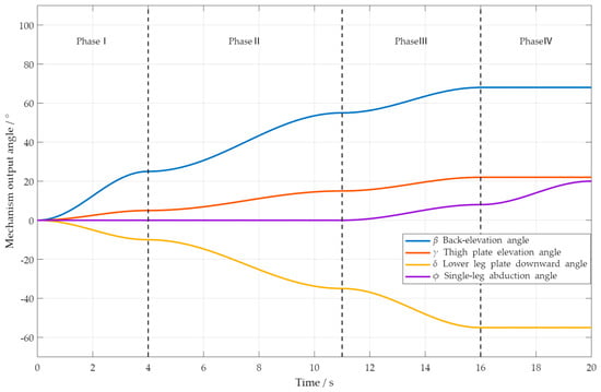
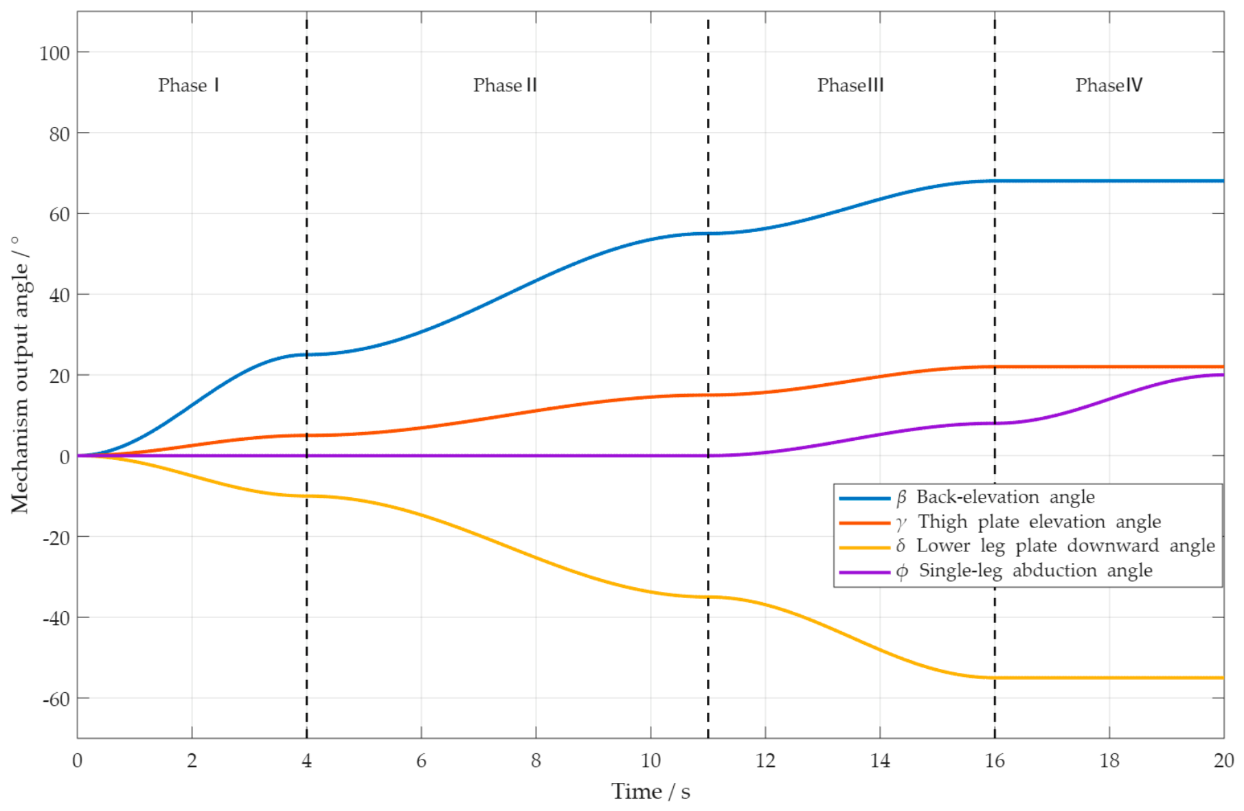
To study the collaborative relationship among the mechanisms during the defecation-assisting posture transition process, the backrest elevation angle a, thigh plate elevation angle b, lower leg plate downward angle c, and single-leg-abduction angle d are planned in stages. Their change curves are shown in Figure 20.
Figure 20.
Change curves of output angles of each mechanism.
It can be seen that the back-elevation, leg-flexion, and leg-abduction movements are not completed simultaneously, but rather proceed in the sequence of “back elevation initiation—leg flexion coordination—posture approximation—leg abduction deployment.” This movement sequence helps avoid hip discomfort caused by direct leg abduction while the body is in a supine position, while also improving the stability of the posture transition process through the supporting effect of the leg-flexion mechanism on the lower limbs.
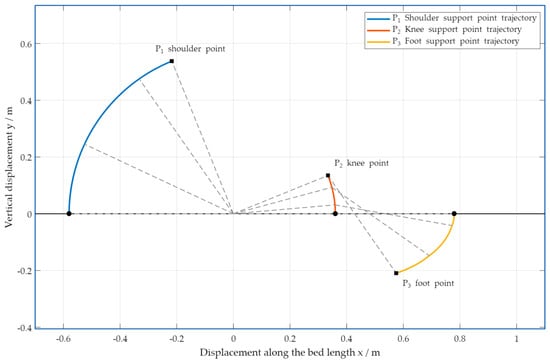
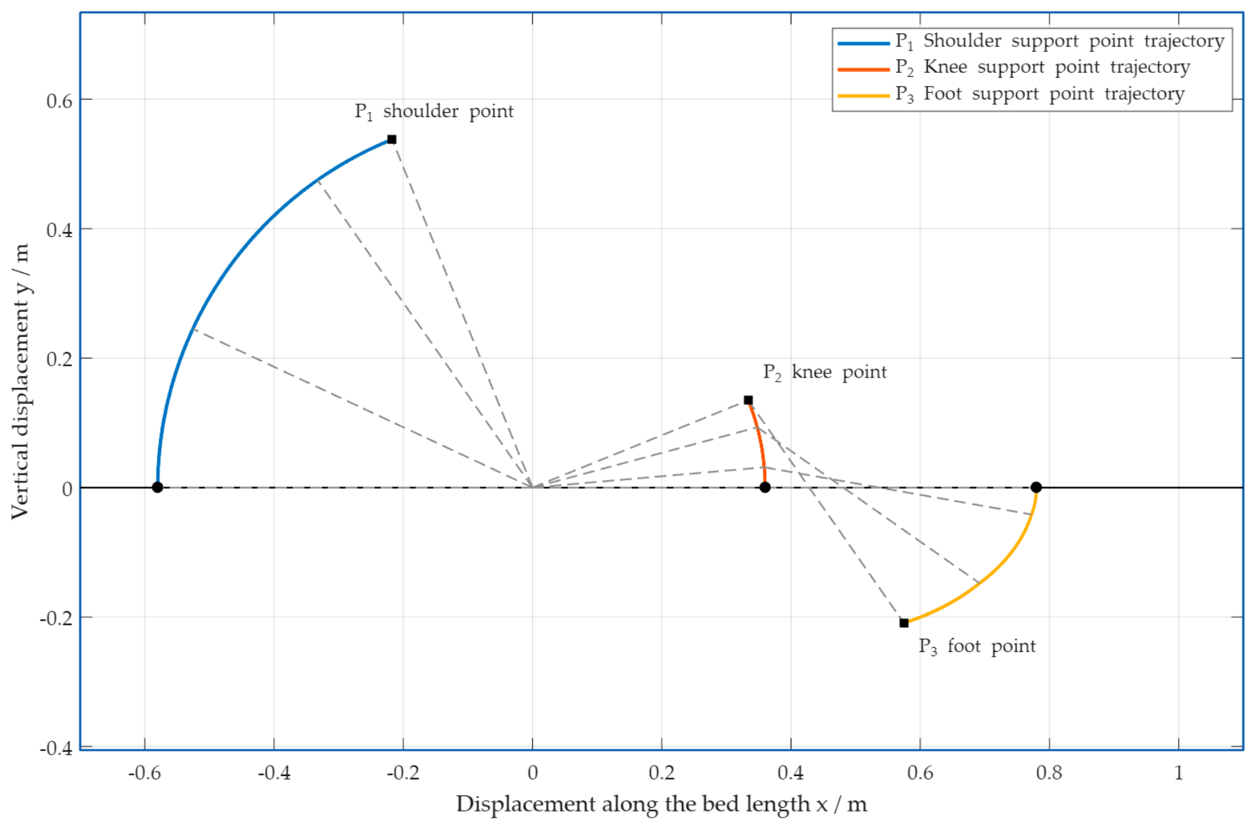
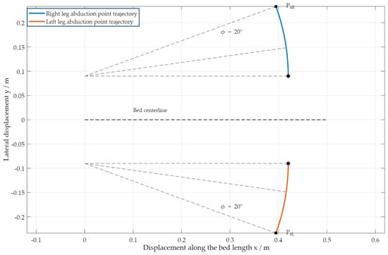
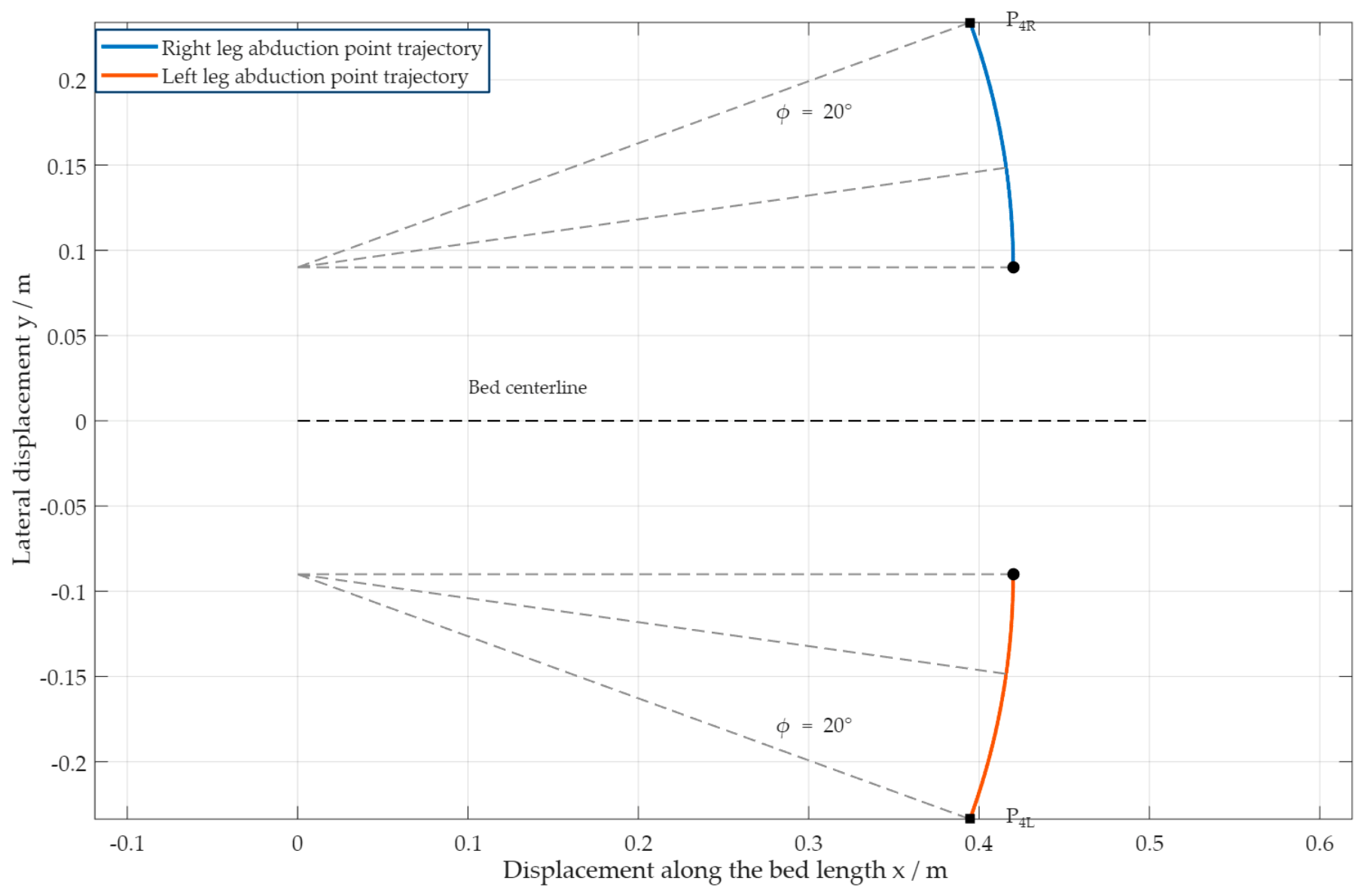
To further analyze the human body’s movement path during the posture transition process, the shoulder support point , knee support point , foot support point , and leg-abduction action point are selected as key analysis points. Here, reflects the support trajectory of the back-elevation mechanism on the upper body; and respectively reflect the action trajectories of the leg-flexion mechanism on the knee and foot; and reflects the action trajectory of the leg-abduction mechanism on the outward movement of both legs.
As can be seen from the side-view trajectory diagram in Figure 21, the shoulder point rises, the knee point moves upward, and the foot point descends. Together, the three form a defecation-assisting posture close to a sitting position.
Figure 21.
Side-view trajectories of key support points.
As can be seen from the leg-abduction trajectory diagram in Figure 22, the left and right leg-abduction action points expand outward along symmetrical arcs, with the single-leg-abduction angle ultimately reaching 20°. This abduction angle not only provides space for bedpan insertion and nursing cleaning, but also avoids discomfort caused by excessive hip joint abduction.
Figure 22.
Top view of leg-abduction trajectories.
Therefore, the defecation-assisting posture transformation mechanism exhibits good continuity and coordination in its movement trajectory, and its final posture can meet the requirements of posture transformation and nursing operation space needed for elderly individuals to defecate in bed.
4.3. Experimental Results and Analysis of Defecation-Receiving Protective Cover Motion Control
4.3.1. Pressure Analysis of the Defecation-Receiving Protective Cover When Conforming to the Human Body
To verify the feasibility of the fuzzy adaptive control algorithm during the human–cover fitting process, contact-force-tracking experiments were conducted. According to the parameter-tuning method described in Section 3.2, the initial control parameters used in the experiments were determined after multiple iterative simulations. Specifically, the reference inertia parameter was = 0.5, the reference damping coefficient was = 80, and the reference stiffness coefficient was = 50. During the experiments, the impedance parameters of each keel segment were kept constant.
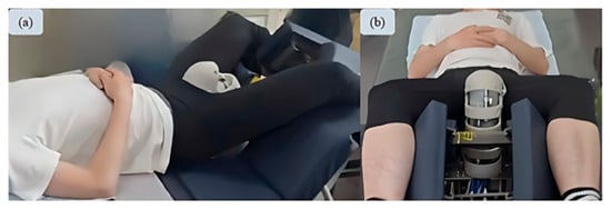
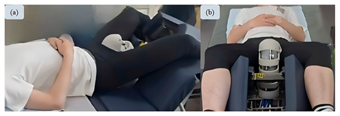
First, the posture transformation mechanism was actuated to position the subject over the excretion opening in the defecation-and-urination posture, as shown in Figure 23. The defecation-receiving protective cover was then actuated. To conform to the body-surface contour, the keel segments of the cover were sequentially bent and adjusted from bottom to top. Once the pressure sensor on the current keel segment detected that the preset contact force had been reached, the next keel segment began to conform to the body surface.
Figure 23.
Relative position between subject and defecation-receiving protective cover. (a) Lateral position; (b) supine position.
The experimental results are shown in Figure 24. As can be seen, the fuzzy adaptive control algorithm rapidly adjusts the actual contact force after each keel segment comes into contact with the human body. Following a brief transient period, the actual contact force stably tracks the expected contact force with a small steady-state error. The experimental results indicate that the selected impedance parameters achieve a favorable balance between response speed and contact stability during the fitting process of the defecation-receiving protective cover.
Figure 24.
The force-tracking curves of the defecation-receiving protective cover. (a) The force-tracking curve of keel segment 1; (b) the force-tracking curve of keel segment 2; (c) the force-tracking curve of keel segment 3; (d) the force-tracking curve of keel segment 4.
4.3.2. Experimental Analysis of the Linear Actuator Strokes and Theoretical Workspace of the Defecation-Receiving Protective Cover
To validate the theoretically calculated linear actuator strokes and the workspace of the cover, experimental tests were conducted using the cover shown in Figure 25. A coordinate system consistent with that of the theoretical model was established. Displacement sensors were used to measure the actual lengths between the upper and lower hinge points of the four linear actuators, while a camera-based vision system was used to measure the end position of the fourth keel segment.
Figure 25.
A prototype of the defecation-receiving protective cover.
Based on the theoretical model, the mechanism configurations corresponding to the maximum and minimum lengths of each linear actuator were calculated, and the prototype was sequentially driven to these configurations. Each configuration was tested three times, and the average value was taken as the experimental result. The experimental stroke of the -th linear actuator is given by:
The relative error between the experimental stroke and the theoretical stroke is given by:
To validate the theoretical workspace, 16 representative test points were uniformly selected along its boundary, and 25 regularly spaced grid points were selected within the region required for conformity to the human body as representative configurations. The corresponding linear actuator lengths were calculated using Equations (14) and (15), and the prototype was driven to each target position. The error between the theoretical and experimental end positions is defined as:
The experimental strokes of the four linear actuators were 34.8 mm, 19.5 mm, 39.2 mm, and 40.9 mm, respectively. Compared with the corresponding theoretical values of 34 mm, 19 mm, 38 mm, and 40 mm, the relative errors were 2.35%, 2.63%, 3.16%, and 2.25%, respectively. The mean and maximum position errors over all test points were 2.3 mm and 3.5 mm, respectively. The experimental results demonstrate that the theoretical model can accurately describe the actual range of motion of the cover end, and that the determined strokes of the four linear actuators satisfy the actuation requirements of the target workspace.
4.4. Comparative Analysis with Existing Excreta-Care Devices
To further demonstrate the practical advantages of the proposed excreta-care device, it is compared with existing wearable and non-wearable excreta-care devices in terms of positioning accuracy, posture transformation, docking accuracy, and nursing convenience, based on the experimental validation results presented above. The comparison results are shown in Table 7.
Table 7.
A comparative analysis of the advantages and disadvantages of defecation-care devices.
The preceding prototype experiments demonstrate that the proposed device can sequentially perform patient repositioning, posture transformation, and the approach, docking, and withdrawal of the defecation-receiving protective cover. No obvious mechanical interference occurred during the operation of the mechanisms, confirming the feasibility of the overall structure and nursing workflow. Compared with existing wearable and non-wearable defecation-care devices, the proposed device offers certain advantages in positioning controllability, rationality of posture transformation, docking stability of the cover, and convenience of nursing operations.
5. Conclusions
- (1)
- A defecation-assisting posture transformation mechanism was proposed, consisting of a translation module and a back-elevation, leg-flexion, and leg-abduction module. Through visual sensing experiments, the motion error of the translation module was determined to be no more than 7.6 mm. Furthermore, an error analysis of the posture transformation process was conducted, and the operational performance of the defecation-assisting posture transformation mechanism was excellent.
- (2)
- A defecation-receiving protective cover with a four-segment keel structure was designed. Through kinematic and workspace analysis, the driving lengths of each keel segment were determined to be 34 mm, 19 mm, 38 mm, and 40 mm, respectively. Based on actual motion control requirements, a fuzzy adaptive control algorithm was adopted for the motion control of the cover. The experimental results show that, although there were minor fluctuations, the cover was able to quickly coordinate with the human body and track to the expected contact-force state.
- (3)
- An unrestrained defecation-assisting care bed was developed, and a corresponding control system was built. The experimental results show that the overall performance was satisfactory.
In follow-up research, we will further optimize the whole device to reduce component weight and refine the defecation posture transformation mechanism and protective cover. Meanwhile, we plan to carry out user experience tests with bedridden elderly target users to collect practical evaluation feedback, conduct torque sensitivity analysis covering different human body weights for the roller translation module, and perform computational fluid dynamics simulation and experimental verification of the flushing bedpan to fully improve the safety and practical performance of the nursing bed.
Author Contributions
Conceptualization, L.S. and H.W.; methodology, L.S. and J.D.; software, Y.N.; validation, L.V. and J.N.; formal analysis, L.S. and J.D.; investigation, Y.N. and J.N.; writing—original draft preparation, L.S. and J.D.; writing—review and editing, L.S. and J.D.; visualization, Y.N.; supervision, H.W.; funding acquisition, L.S. All authors have read and agreed to the published version of the manuscript.
Funding
This research were funded by the Public Welfare Program of Ningbo Municipal Bureau of Science and Technology (grant number 2024S049), Ningbo Polytechnic Talent Introduction Project (grant number NZ25RC019) and Opening Project of Ningbo Key Laboratoryof Aging Health Equipment and Service Technology (NZ25KF101).
Institutional Review Board Statement
The study was conducted in accordance with the Declaration of Helsinki, and approved by the Ethics Committee of Yangming College, Ningbo Polytechnic (protocol code [2026]LLSP(0310), date of approval: 10 March 2026).
Informed Consent Statement
Informed consent was obtained from all subjects involved in the study.
Data Availability Statement
Data are contained within the article.
Conflicts of Interest
The authors declare no conflicts of interest.
References
- Berger, B.; Graeb, F.; Baumann, M.; Wolke, R. Becoming Bedridden and Being Bedridden: Implications for Nursing and Care for Older People in Long-Term Care: A Scoping Review. Int. J. Older People Nurs. 2025, 20, e70015. [Google Scholar] [CrossRef] [Scilit] [PubMed]
- Shogenji, M.; Yoshida, M.; Kakuchi, T.; Hirako, K. Factors associated with caregiver burden of toileting assistance at home versus in a nursing home: A cross-sectional study. PLoS ONE 2024, 19, e0299721. [Google Scholar] [CrossRef] [Scilit] [PubMed]
- Ostaszkiewicz, J.; Dickson-Swift, V.; Hutchinson, A.; Wagg, A. A concept analysis of dignity-protective continence care for care dependent older people in long-term care settings. BMC Geriatr. 2020, 20, 266. [Google Scholar] [CrossRef] [Scilit] [PubMed]
- Cornejo, J.; Huamanchahua, D.; Huamán-Vizconde, S.; Terrazas-Rodas, D.; Sierra-Huertas, J.; Janampa-Espinoza, A.; Gonzáles, J.; Cardona, M. Mechatronic Exoskeleton Systems for Supporting the Biomechanics of Shoulder-Elbow-Wrist: An Innovative Review. In Proceedings of the 2021 IEEE International IOT, Electronics and Mechatronics Conference (IEMTRONICS), Toronto, ON, Canada, 21–24 April 2021; pp. 1–9. [Google Scholar]
- Cailleteau, P.S.; Cadon, L.; Paille, C.; Olivier, E.; Rulleau, T. Assessment of perceived patient comfort and ease of bedpan handling by caregivers, a cross-sectional survey. PLoS ONE 2024, 19, e0306773. [Google Scholar] [CrossRef] [Scilit] [PubMed]
- Sakakibara, R.; Tsunoyama, K.; Hosoi, H.; Takahashi, O.; Sugiyama, M.; Kishi, M.; Ogawa, E.; Terada, H.; Uchiyama, T.; Yamanishi, T. Influence of Body Position on Defecation in Humans. Luts-Low. Urin. Tract. Symp. 2010, 2, 16–21. [Google Scholar] [CrossRef] [Scilit] [PubMed]
- Imai, M.; Kuwahara, Y.; Hirai, M.; Nishimura, R.; Nishimura, N.; Shimizu, Y.; Fujii, T.; Iwase, S. Effects of Defecation Strain at Various Bed Reclining Angles on Intrarectal Pressure and Cardiovascular Responses. Nurs. Res. 2015, 64, 413–421. [Google Scholar] [CrossRef] [Scilit] [PubMed]
- Kottner, J.; Dissemond, J. Incontinence-Associated Dermatitis in Older Adults: A Critical Review of Risk Factors, Prevention and Management. Drugs Aging 2025, 42, 745–754. [Google Scholar] [CrossRef] [Scilit] [PubMed]
- Gray, M.; Giuliano, K.K. Incontinence-Associated Dermatitis, Characteristics and Relationship to Pressure Injury: A Multisite Epidemiologic Analysis. J. Wound Ostomy Contin. Nurs. 2018, 45, 63–67. [Google Scholar] [CrossRef] [Scilit] [PubMed]
- Weiner, C.; Alperovitch-Najenson, D.; Ribak, J.; Kalichman, L. Prevention of Nurses’ Work-Related Musculoskeletal Disorders Resulting From Repositioning Patients in Bed Comprehensive Narrative Review. Workplace Health Saf. 2015, 63, 226–232. [Google Scholar] [CrossRef] [Scilit] [PubMed]
- Wiggermann, N.; Zhou, J.; McGann, N. Effect of Repositioning Aids and Patient Weight on Biomechanical Stresses When Repositioning Patients in Bed. Hum. Factors 2021, 63, 565–577. [Google Scholar] [PubMed]
- Choi, K.H.; Kojeongbae; Lee, H.; HOSANG, L.; Lee, H.K.; Kong, Y.K.; Shimhyunho; Keum, H.; Won, B.H. Development and Application of an Evaluation Method for Quantifying Care Burden of Excretion: A Comparison between Manual and Robot-aided Care. J. Ergon. Soc. Korea 2025, 44, 155–173. [Google Scholar] [CrossRef] [Scilit]
- Ko, J.B.; Kong, Y.K.; Choi, K.H.; Lee, C.K.; Keum, H.J.; Hong, J.S.; Won, B.H. Comparison of the Physical Care Burden on Formal Caregivers between Manual Human Care Using a Paper Diaper and Robot-Aided Care in Excretion Care. Int. J. Environ. Res. Public Health 2023, 20, 1281. [Google Scholar] [CrossRef] [Scilit] [PubMed]
- Jia, T.Y.; Pan, F.Y.; Yang, X.C.; Ji, L.H.; Farina, D.; Li, C. Artificial Empathy in Therapy and Healthcare: Advancements in Interpersonal Interaction Technologies. Cyborg Bionic Syst. 2025, 6, 0473. [Google Scholar] [CrossRef] [Scilit] [PubMed]
- Dong, L.P.; Zhang, X.X.; Li, M.; Li, Y.; Guo, J.Y.; Lu, S.R.; Peng, Z.Y.; Zhen, C.X.; Hui, Y.F.; Shao, X.P.; et al. AI-Enabled Wearable Ultrasound for NonInvasive Central Venous Pressure Monitoring. Cyborg Bionic Syst. 2025, 7, 0653. [Google Scholar]
- Ever Care Inc. Ever Care: Automatic Urine/Feces Disposal System. Available online: https://www.mhlw.go.jp/content/12300000/000613125.pdf?utm_source=chatgpt.com (accessed on 10 March 2025).
- Guangzhou Hekang Biotechnology Co., Ltd. Automatic Urine and Feces Disposal System. Available online: https://www.he-kang.com/ (accessed on 10 March 2025).
- Daneen Medical Technology (Zhejiang) Co., Ltd. Intelligent Care Robot. Available online: https://daneenon.com/ (accessed on 10 March 2025).
- Hu, B.S.; Chen, Z.W.; Chen, X.Y.; Lu, S.; Su, Y.B.; Yu, H.L. Research of System Design and Automatic Detection Method for Excretion Nursing Equipment. Healthcare 2023, 11, 388. [Google Scholar] [CrossRef] [Scilit] [PubMed]
- Tokoro, K.; Hashimoto, T.; Kobayashi, H. Development of Robotic Defecation Simulator. J. Robot. Mechatron. 2014, 26, 377–387. [Google Scholar] [CrossRef] [Scilit]
- Salzmann-Erikson, M.; Eriksson, H. Absorbability, applicability and availability in nursing and care robots: A thematic analysis of Twitter postings. Telemat. Inform. 2018, 35, 1553–1560. [Google Scholar] [CrossRef] [Scilit]
- Andhare, A.B.; Onkar, A.M. Design and development of multifunctional patient bed with integrated toilet. SN Appl. Sci. 2021, 3, 813. [Google Scholar] [CrossRef] [Scilit]
- Zhou, H.Y.; Sang, L.F.; Luo, J.J.; Wang, H.B.; Feng, Y.F.; Zhang, X.Z.; Chen, L. Development of a multifunctional nursing bed system for in-bed position recognition and automatic repositioning. Proc. Inst. Mech. Eng. Part C-J. Mech. Eng. Sci. 2024, 238, 5437–5454. [Google Scholar] [CrossRef] [Scilit]
- Rozas Llontop, D.A.; Cornejo, J.; Palomares, R.; Cornejo-Aguilar, J.A. Mechatronics Design and Simulation of Anthropomorphic Robotic Arm mounted on Wheelchair for Supporting Patients with Spastic Cerebral Palsy. In Proceedings of the 2020 IEEE International Conference on Engineering Veracruz (ICEV), Veracruz, Mexico, 26–29 October 2020; pp. 1–5. [Google Scholar]
- Cheng, G.; Huang, Y.J.; Zhang, X.M.; Chen, H.Y.; Ota, J. An overview of transfer nursing robot: Classification, key technology, and trend. Robot. Auton. Syst. 2024, 174, 104653. [Google Scholar] [CrossRef] [Scilit]
- Wang, X.; Cho, C.; Zhang, P.; Ge, S.; Wang, L. Design Methodology for a Backrest-Lifting Nursing Bed Based on Dual-Channel Behavior-Emotion Data Fusion and Biomechanical Simulation: A Human-Centered and Data-Driven Optimization Approach. Biomimetics 2025, 10, 764. [Google Scholar] [CrossRef] [Scilit] [PubMed]
- Ning, Y.S.; Sang, L.F.; Wang, Z.C.; Ghinoiu, B.; Lu, F.Q.; Wang, H.B.; Vladareanu, L. Design, Simulation, and Testing of Active Cooperative Control Strategies for a Light Sensation Transfer Nursing Robot. Actuators 2025, 14, 95. [Google Scholar] [CrossRef] [Scilit]
- Baek, J. Smart predictive analytics care monitoring model based on multi sensor IoT system: Management of diaper and attitude for the bedridden elderly. Sens. Int. 2023, 4, 100213. [Google Scholar] [CrossRef] [Scilit]
- Xiao, Y.X.; Liu, T.; Meng, C.Z.; Jiao, Z.A.; Meng, F.C.; Guo, S.J. Numerical simulation modeling and kinematic analysis onto double wedge-shaped airbag of nursing appliance. Sci. Rep. 2023, 13, 14261. [Google Scholar] [CrossRef] [Scilit] [PubMed]
- Cornejo, J.; Cornejo-Aguilar, J.A.; Vargas, M.; Helguero, C.G.; Milanezi de Andrade, R.; Torres-Montoya, S.; Asensio-Salazar, J.; Rivero Calle, A.; Martínez Santos, J.; Damon, A.; et al. Anatomical Engineering and 3D Printing for Surgery and Medical Devices: International Review and Future Exponential Innovations. BioMed Res. Int. 2022, 2022, 6797745. [Google Scholar] [CrossRef] [Scilit] [PubMed]
- GB/T 10000-2023; Human Dimensions of Chinese Adults. State Administration for Market Regulation of China. Standardization Administration of China: Beijing, China, 2023. (In Chinese)
- Nacarino, A.; La-Rosa, A.; Quispe, Y.; Castro, K.; Valer, F.S.; Cornejo, J.; Vargas, M.; Castro, R.; Palomares, R.; Sanchez, B.; et al. Bio-Mechatronics Design and Manufacturing of Arm Exoskeleton with Electro-Pneumatic Mechanism for Passive Rehabilitation. Int. J. Technol. 2024, 15, 1730–1748. [Google Scholar] [CrossRef] [Scilit]
- Tashiro, D.; Nakahara, M.; Kitajima, E.; Hida, K. Respiratory function and comfort levels in three different defecatory simulation postures in the elderly. Indian J. Gastroenterol. 2021, 40, 131–136. [Google Scholar] [CrossRef] [Scilit] [PubMed]
- Modi, R.M.; Hinton, A.; Pinkhas, D.; Groce, R.; Meyer, M.M.; Balasubramanian, G.; Levine, E.; Stanich, P.P. Implementation of a Defecation Posture Modification Device Impact on Bowel Movement Patterns in Healthy Subjects. J. Clin. Gastroenterol. 2019, 53, 216–219. [Google Scholar] [PubMed]

Disclaimer/Publisher’s Note: The statements, opinions and data contained in all publications are solely those of the individual author(s) and contributor(s) and not of MDPI and/or the editor(s). MDPI and/or the editor(s) disclaim responsibility for any injury to people or property resulting from any ideas, methods, instructions or products referred to in the content. |
© 2026 by the authors. Licensee MDPI, Basel, Switzerland. This article is an open access article distributed under the terms and conditions of the Creative Commons Attribution (CC BY) license.