


Abstract
In-wheel motor drive systems can increase vehicle unsprung mass and thereby alter suspension dynamics. This study investigates the frequency-domain mechanisms through which an unsprung mass increment affects ride comfort, suspension working space, and road holding, and proposes a frequency-partitioned active impedance control (FPAIC) strategy. A structural sensitivity operator, M(s), is derived from a linear quarter-car model to quantify the mass-perturbation effect and to identify inertia, damping, and tire stiffness as the principal physical propagation channels. Guided by this mapping, the commanded active force is decomposed into virtual-inertia, virtual-damping, and virtual-stiffness components, which are scheduled according to the estimated dominant excitation frequency. Under swept-frequency simulations with Δmu = 60 kg, the comfort-prioritized LQR benchmark reduces the sprung-mass-acceleration RMS to 93.8% of the baseline but increases the tire-deflection RMS to 144.1%, whereas the road-holding-prioritized H∞ benchmark reduces the tire-deflection RMS to 99.1% at the cost of increasing the sprung-mass-acceleration RMS to 170.9%. The FPAIC yields corresponding RMS values of 98.9%, 85.9%, and 99.4% for sprung-mass acceleration, suspension deflection, and dynamic tire deflection, respectively. Overall, the results demonstrate mechanism-guided coordination across ride comfort, suspension working space, and road holding, while the Δmu = 40 kg case shows that the unchanged FPAIC parameterization retains its mitigation effect without retuning.
1. Introduction
Vehicle suspension systems are essential to vehicle dynamics because they affect ride comfort, handling stability, and road holding. As a primary means of enhancing vehicle performance, active suspensions aim to regulate the dynamic responses between the vehicle body and wheels through external control forces. Traditional control strategies, such as Proportional–Integral–Derivative (PID) control and the Linear Quadratic Regulator (LQR), were widely adopted in early active suspension research because of their structural simplicity and ease of implementation [1,2,3]. With the advancement of control theory, advanced strategies, including control, -synthesis [4,5,6], Model Predictive Control (MPC) [7,8,9], and intelligent control methods such as sliding mode and fuzzy logic [10,11,12,13,14], have been applied to improve suspension performance under complex and uncertain conditions.
However, under operating conditions involving a large unsprung mass increment, such as in-wheel motor integration, the frequency-domain response characteristics of the suspension may change appreciably. In particular, the wheel-hop resonance tends to shift toward the lower-frequency range, strengthening the coupling between the sprung-mass and wheel-hop modes. This effect can degrade road-holding-related indicators [15]. For conventional full-band controllers, a single set of feedback weights may be insufficient to simultaneously address the distinct requirements of low-frequency ride comfort and high-frequency wheel-hop suppression, leading to a cross-band performance trade-off.
To address these frequency-dependent characteristics, researchers have explored frequency-domain methods for suspension analysis and control. Traditional techniques, such as Frequency Response Functions and Bode plots, are widely used for parameter sensitivity studies in passive suspension systems [16,17]. For active and semi-active control synthesis, frequency-weighted optimization [5], finite-frequency design [15], and frequency-adaptive regulation [18,19] have been proposed. These approaches provide useful tools for narrowband adjustment or global performance optimization. However, their controller parameters are typically determined through weighting functions, empirical tuning, or numerical cost-function design, and the explicit correspondence between control parameters and physical impedance channels, namely inertia, damping, and stiffness, is not always directly available. This limits their ability to provide a channel-based explanation of how the control force reshapes the suspension dynamics under unsprung mass variations.
Related multi-parameter optimization has also been investigated in other coupled vibration-control systems. Wang et al. employed an improved niche genetic algorithm to coordinate the stiffness and longitudinal installation positions of multiple underframe-suspended equipment units while balancing carbody vibration reduction and equipment vibration limits in a high-speed railway vehicle [20]. Although the application object and design variables differ from those in the present active suspension, this study demonstrates the importance of coordinating multiple physical parameters and vibration objectives in coupled dynamic systems.
In robotics and high-precision mechanical systems, impedance control achieves frequency-dependent tuning by decomposing dynamic behavior into inertia, damping, and stiffness channels [21,22,23]. This concept provides a valuable physical channel decomposition framework that can be adapted to address frequency-dependent control problems in suspension systems. Impedance-based concepts have also been introduced directly into active suspension control. Fateh and Alavi formulated an impedance controller for an active suspension system, Dehghan et al. subsequently incorporated fuzzy supervisory regulation into an impedance-control framework, and Zhang et al. recently investigated impedance-control design for active suspensions [24,25,26]. Building on this line of research, the present study starts from a mass-perturbation-derived frequency-domain representation and uses the resulting mechanism-frequency-channel mapping to coordinate the virtual inertia, damping, and stiffness components.
Accordingly, the principal contributions of this study are threefold. First, a characteristic-polynomial-normalized structural sensitivity operator is formulated for the unsprung mass increment, providing a unified frequency-domain representation of the common denominator perturbation and the additional numerator perturbation in the tire response. Second, the propagation of the adverse effects is explicitly mapped to the inertia, damping, and tire-stiffness channels, thereby establishing an interpretable mechanism–frequency–channel relationship rather than relying solely on numerical response comparisons. Third, this mapping is translated into a frequency-partitioned active impedance control strategy, in which the active force is decomposed into frequency-scheduled virtual-inertia, virtual-damping, and virtual-stiffness components. Its multi-indicator coordination and parameter reuse at a second mass level are evaluated through comparisons with passive, LQR, and active suspensions and through an additional unsprung-mass-increment case without controller retuning.
The remainder of this paper is organized as follows. Section 2 establishes the quarter-car model and formulates the frequency-domain performance transfer functions. Section 3 develops the structural-sensitivity description of the unsprung mass increment and identifies the associated inertia, damping, and tire-stiffness channels. Section 4 formulates the FPAIC framework, including the active-impedance operators, frequency scheduling, and state and frequency estimation. Section 5 evaluates the proposed framework through swept-frequency simulations, controller comparisons, an additional mass-level case, and active-force-demand assessment. Finally, Section 6 summarizes the main conclusions and outlines the staged validation roadmap.
2. Quarter-Car Modeling and Frequency-Domain Formulation
This section establishes the analytical foundation for the subsequent mechanism analysis and control design. A linear 2-DOF quarter-car model is first formulated based on vertical force equilibrium, after which the characteristic polynomial and transfer functions for sprung-mass acceleration, suspension deflection, and dynamic tire deflection are derived. These expressions provide the nominal frequency-domain reference for evaluating the effects of the unsprung mass increment.
2.1. Dynamic Baseline Model
To systematically investigate the changes in suspension dynamics induced by the unsprung mass increment, this paper adopts the classic quarter-car two-degree-of-freedom (2-DOF) vertical dynamic model as the analytical baseline. Although high-DOF full-vehicle models can capture richer kinematic details, the 2-DOF model offers distinct analytical advantages for the core objective of this study—specifically, understanding how unsprung mass variations alter the modal coupling between the sprung-mass and wheel-hop resonances. The model separates the vertical interactions between the sprung and unsprung masses and provides closed-form frequency-domain expressions. These properties make it suitable for formulating the structural sensitivity operator and identifying the relevant physical parameter channels.
As shown in Figure 1, the model consists of a sprung mass and an unsprung mass . A suspension spring with stiffness and a damper with damping coefficient are connected in parallel between the two masses, while the tire is represented by an equivalent vertical stiffness interacting with the road input. The vertical displacements , , and are measured from the static equilibrium position, with the upward direction defined as positive. Consequently, the static gravitational forces are eliminated from the incremental dynamic equations. The suspension force acting on the sprung mass is , and the corresponding force acting on the unsprung mass has the opposite direction. The tire restoring force acting on the unsprung mass is . Applying Newton’s second law separately to the sprung and unsprung masses yields the following coupled dynamic equations:
Figure 1.
Quarter-car 2-DOF vertical dynamic model.
The model is formulated about the static equilibrium position and assumes small-amplitude vertical motion, continuous tire–road contact, and linear characteristics of the suspension spring, damper, and equivalent tire stiffness. Accordingly, the structural-sensitivity analysis, physical channel identification, and model-based validation of the FPAIC are established within the scope of small-signal vertical dynamics about a fixed operating condition. Within this scope, the model isolates how an unsprung mass increment reshapes the sprung-mass and wheel-hop modes and the associated inertia, damping, and stiffness transmission channels. It does not represent tire-contact loss or stiffness saturation, damper friction and hysteresis, bump-stop engagement, suspension-linkage kinematics and motion-ratio variation, load transfer, or the pitch, roll, and four-wheel coupling of a full vehicle. Extension to a higher-fidelity model can retain the mechanism-guided workflow, but it requires the present scalar transfer functions and sensitivity operator to be reformulated as operating-point-dependent, coupled, multi-input/multi-output relationships, together with re-identification of the impedance-channel mapping for the additional vehicle modes.
To highlight the dominant physical mechanisms, this model neglects the relatively small tire damping in the theoretical derivation. This simplification is justified because the inclusion of only slightly affects the damping ratios of the characteristic polynomial’s poles, without altering the algebraic structure of the numerator polynomial in the structural sensitivity operator formulated in subsequent sections. Therefore, for identifying the physical channels of negative effect propagation, this simplification enhances the clarity of the mathematical expressions while preserving the validity of the qualitative conclusions. Table 1 lists the baseline parameters of the system adopted in this study. The baseline parameter set is not associated with a specific production model but is selected to represent a generic mid-size passenger car. Under the assumption of four identical quarter-car units, it corresponds to an equivalent total vehicle mass of approximately 1502 kg, comprising a total sprung mass of 1328 kg and a baseline unsprung mass of 174 kg. This approximately 1.5-ton vehicle scale is broadly consistent with a conventional mid-size sedan and is adopted as the nominal platform for the subsequent mechanism analysis and control evaluation.
Table 1.
Baseline parameters of the quarter-car model.
2.2. Characteristic Polynomial and Performance Transfer Functions
Assuming zero initial conditions, the characteristic polynomial governing the global dynamics of the system can be derived via the Laplace transform:
The characteristic polynomial determines the pole distribution and describes the frequency shifts, amplitude peaks, and interaction mechanisms between the sprung-mass and wheel-hop resonances.
This study selects three representative vertical dynamic performance metrics as the research objectives, corresponding to ride comfort, suspension working space constraints, and tire road-holding capability. Addressing the standard multi-objective optimization requirements for suspension systems, the frequency-domain transfer functions for the three primary vertical dynamic performance indicators are defined as follows.
Sprung mass acceleration transfer function :
This indicator directly reflects the ride comfort perceived by passengers and serves as the primary metric for evaluating the effectiveness of active vibration isolation.
Suspension deflection transfer function :
This function represents the utilization of the suspension of the working space under dynamic excitation. An excessive peak indicates a significant risk of the suspension bottoming out (i.e., hitting the mechanical bump stops).
Tire deflection transfer function :
The magnitude of the gain peak near the wheel-hop frequency band serves as the core criterion for determining whether a significant increase in unsprung mass compromises the vehicle’s road-holding capability.
This section establishes a passive quarter-car baseline model for frequency-domain mechanism analysis and formulates three categories of performance transfer functions corresponding to ride comfort, suspension constraints, and road holding. This modeling framework provides a unified mathematical foundation for the subsequent sensitivity analysis of the unsprung mass increment .
3. Unsprung Mass Sensitivity and Physical Channel Analysis
Unlike conventional parameter-variation analyses that mainly focus on numerical changes, this paper treats the unsprung mass increment introduced by in-wheel motors as a structural perturbation that can modify the frequency-domain dynamic characteristics of the system. This section aims to explicitly isolate the intervention paths of this perturbation and systematically identify the key physical channels governing the propagation of adverse effects through the formulation of a structural sensitivity operator.
3.1. Structural Introduction of the Unsprung Mass Increment
The actual unsprung mass is expressed as the sum of the nominal mass and the increment , such that . Substituting this into the characteristic polynomial of the passive system yields a new characteristic structure under the mass increment:
where is defined as the unsprung mass perturbation polynomial. This algebraic formulation demonstrates that the introduction of does not merely alter a single coefficient in isolation; rather, it systematically reconstructs the fourth- to second-order dynamic terms of the system through a unified perturbation polynomial.
Building on this, the transfer functions for the sprung-mass acceleration and suspension deflection are derived as follows:
Under this framework, the numerator terms of the new transfer functions for sprung-mass acceleration and suspension deflection ( and ) remain unchanged. The adverse effects primarily manifest themselves through the redistribution of the denominator poles (i.e., resonance frequency shifts and enhanced modal coupling).
In contrast, the evolution of tire deflection is more complex. Its new numerator term can be rearranged as follows:
Consequently, the dynamic tire deflection transfer function takes the following form:
This reveals that the tire-side performance is not only subject to the impact of denominator pole shifts but is also directly modulated by the additional perturbation on the numerator side (a dual-sided perturbation mechanism). Therefore, dynamic tire deflection inherently exhibits the highest frequency-domain sensitivity to the unsprung mass increment.
3.2. Formulation and Dynamic Implications of the Structural Sensitivity Operator
To explicitly isolate the intervention path of from the passive dynamic baseline, this paper formulates the following frequency-domain structural sensitivity operator :
In the present model, is exactly the partial derivative of the characteristic polynomial with respect to the unsprung mass, i.e., . Hence, is the characteristic-polynomial-normalized form of the conventional parameter derivative. If the normalized parameter sensitivity is defined as , then . Accordingly, has units of , whereas is dimensionless. Therefore, is not introduced as an alternative to derivative-based sensitivity, but as a problem-specific representation that embeds the unsprung mass perturbation directly into the characteristic structure. Using this operator, the perturbed characteristic polynomial associated with the unsprung mass increment can be expressed as follows:
Because the characteristic polynomial depends affinely on , Equation (12) is an exact factorization for a finite mass increment within the present linear model, rather than a first-order approximation.
Furthermore, the three performance transfer functions can be uniformly expressed in the following sensitivity-modulated forms:
The dimensionless product represents the frequency-dependent relative perturbation of the common characteristic polynomial. Equations (13)–(15) show that the sprung-mass acceleration and suspension deflection responses are modified through the same denominator factor , whereas the tire-deflection response additionally contains the corresponding numerator perturbation. This unified representation makes the dual-sided perturbation mechanism of the tire response explicit and provides a direct analytical connection among the mass increment, the sensitive frequency bands, and the physical impedance channels used in the subsequent control design.
Moreover, according to the high-frequency asymptotic property of the operator, , the high-frequency sensitivity is inversely proportional to the nominal unsprung mass. Coupled with the approximate wheel-hop modal frequency , this result indicates a twofold degradation characteristic: the system remains sensitive to the added mass perturbation in the high-frequency range, and the wheel-hop-sensitive band shifts toward the lower-frequency working range of the vehicle.
As illustrated in Figure 2, an increase in amplifies the influence of near the wheel-hop-sensitive band and redistributes the system’s mid-to-high-frequency response. Both the sprung-mass acceleration and suspension deflection exhibit a downward migration of the wheel-hop-related peak, while the peak-gain variation is more evident in the suspension deflection response. Furthermore, because tire deflection is affected by perturbations in both the numerator and denominator, it exhibits the strongest peak amplification and frequency shift among the three performance indicators.
Figure 2.
Analysis of the adverse effects of the unsprung mass increment transmitted via the sensitivity operator.
3.3. Propagation Characteristics of Unsprung Mass Adverse Effects Across Performance Dimensions
Based on the modulation mechanism of the structural sensitivity operator , the unsprung mass increment exhibits significantly differentiated propagation patterns across the three core performance outputs.
Regarding the sprung-mass acceleration response, the core impact of manifests as the attenuation of modal isolation between the sprung-mass resonance and the wheel-hop resonance. As the wheel-hop mode shifts toward the low-frequency region, the mid-to-high-frequency vibration energy originally confined to the wheel side is transmitted to the sprung mass through enhanced modal coupling. Macroscopically, this results in an overall elevation of mid-to-high-frequency acceleration amplitudes and a shrinkage of the system’s comfort bandwidth.
For the suspension deflection response, alters the inertia matching ratio between the sprung and unsprung masses, inducing a systematic migration in the frequency band distribution of the suspension’s relative motion. Consequently, the resonance peak of the suspension deflection increases and shifts to a lower frequency, subjecting the suspension working space to more stringent dynamic constraints over a broader frequency band.
Concerning the dynamic tire deflection response, the tire-side performance exhibits the highest sensitivity to the unsprung mass. Jointly modulated by the dual perturbations of the transfer function’s numerator and denominator, the dynamic force transmission path on the tire–road interface is reshaped, leading to evident peak amplification and frequency-shift effects, particularly near the wheel-hop-sensitive band. Given that the dynamic tire force and tire deflection share a direct linear mapping relationship via , road holding is highly sensitive to the increase in unsprung mass . Therefore, the active control law should prioritize compensation of the impedance mismatch at the tire–road interface.
3.4. Passive Parameter Space Sweep and Identification of Key Physical Channels
Having defined the frequency-domain structure of , identifying the key passive parameters governing the propagation of the adverse effects of unsprung mass becomes a prerequisite for active impedance control design. Based on , this study conducts a full-frequency parameter sweep across , , , , and (as illustrated in Figure 3).
Figure 3.
Comprehensive parameter sweep of the sensitivity function .
The sweep results reveal significant disparities in the modulation effects of these parameters on . Specifically, and exert a relatively weak influence on the sensitivity peak and the wheel-hop-sensitive band. Conversely, , , and substantially alter the peak position, peak gain, and bandwidth broadening of within the critical frequency bands. By integrating the systematic sweeps of the three performance indicators (Figure 4, Figure 5 and Figure 6), the specific operational boundaries governed by these three key physical channels are further delineated.
Figure 4.
Analysis of the influence of the baseline unsprung mass parameter .
Figure 5.
Analysis of the influence of the baseline damping parameter .
Figure 6.
Analysis of the influence of the baseline tire stiffness parameter .
Inertia channel (): This parameter determines the baseline inertial scale of the wheel-hop mode. As increases, the wheel-hop mode systematically shifts toward lower frequencies, causing the wheel-hop-sensitive band—originally confined to the high-frequency region—to gradually encroach into the vehicle’s dominant operational frequency range. Consequently, the channel fundamentally governs the frequency-domain distribution of the adverse effects.
Damping channel (): As the primary energy dissipation element of the system, directly dictates the quality factor of the resonance peaks. Increasing the damping effectively attenuates the peak gains within the wheel-hop and modal coupling bands; however, excessive damping forces exacerbate the rigid transfer of high-frequency vibrations to the sprung mass. Thus, the channel governs the peak intensity of the adverse effects and simultaneously establishes the fundamental trade-off boundary between ride comfort and peak suppression capability.
Tire stiffness channel (): serves as the core parameter defining the wheel-hop modal frequency, tire road-holding characteristics, and impact transmissibility. A smaller tends to attenuate mid-to-high-frequency impact transmission, whereas a larger enhances the dynamic constraints at the tire–road interface. This channel fundamentally embodies the inherent conflict between ride comfort and road holding, demarcating the physical boundaries for multi-objective optimization.
Synthesizing the results from Figure 3, Figure 4, Figure 5 and Figure 6, the frequency-domain propagation of the adverse effects of unsprung mass unfolds primarily along three physical paths corresponding to , , and . These channels determine the frequency distribution, the peak intensity of the adverse effects, and the conflict boundary between ride comfort and road holding, respectively. Theoretically, this identification process transforms the subsequent active control parameter tuning problem into a targeted frequency-shaping task directed precisely at these three physical impedance channels. In this paper, this channel-level representation is referred to as suspension impedance dynamics, because the adverse effects of the unsprung mass increment are interpreted through the frequency-dependent inertia, damping, and tire-stiffness paths of the suspension system.
By explicitly introducing the mass perturbation term , this section formulated the structural sensitivity operator to characterize its frequency-domain propagation mechanism. Furthermore, it systematically analyzed the distinct propagation patterns of these adverse effects across three dimensions: ride comfort, suspension working space, and road holding. The analysis demonstrates that the adverse effects of exhibit pronounced frequency selectivity and channel dependency, with their propagation paths jointly governed by the inertia, damping, and tire stiffness channels. Given the theoretical limitations of traditional passive parameter optimization in addressing such structural mismatches, the subsequent active control design is therefore formulated as a “frequency-partitioned active impedance reconstruction”.
4. Frequency-Partitioned Active Impedance Control
Analysis demonstrates that the adverse effects of unsprung mass are not uniformly distributed across the frequency spectrum; instead, they exhibit pronounced frequency selectivity along key physical channels. This dynamic evolution pattern motivates an active-control representation that links the resultant force command to the frequency-dependent physical channels identified above. Accordingly, the controller is formulated as an active impedance network capable of targeted reconstruction of the system’s inertia, damping, and stiffness channels, while incorporating frequency-aware scheduling.
4.1. From Resultant-Force Feedback to Active Impedance Reconstruction
In many active-suspension controllers based on state or output feedback, the control action is implemented as a resultant force command. This force-level representation is effective for closed-loop synthesis, but by itself it does not reveal how the commanded force relates to the inertia, damping, and tire-stiffness channels identified in Section 3.
To improve the physical interpretability of the control action, this paper formulates an active impedance operator network, decomposing the control law into components associated with the three critical physical channels:
where , , and are dimensionless frequency-scheduling gains corresponding to the active inertia, damping, and stiffness impedances, respectively. This baseline mapping strategy not only ensures strict dimensional homogeneity between each control component and its original physical channel but also recasts the control task as the regulation of reconstruction intensity in the corresponding physical channels.
For clarity, the three terms in Equation (16) are denoted as , , and , respectively, with .
4.2. Physical Implementation Architecture of the FPAIC
As illustrated in Figure 7, the physical suspension retains the fixed passive spring , passive damper , and tire stiffness , while a linear electromagnetic actuator is installed in parallel between the sprung and unsprung masses.
Figure 7.
Conceptual implementation architecture and signal flow of the FPAIC-based active suspension.
To connect the control law to its physical implementation, the three terms in Equation (16) are denoted as , , and , respectively, and their sum forms the single-actuator command . These quantities are software-defined impedance-force components rather than commands to three physically adjustable suspension devices.
The virtual damping and stiffness effects are realized by the active force generated by this actuator rather than by directly changing the physical damping or stiffness coefficients. Specifically, emulates the required damping-channel modification through a force proportional to the processed suspension relative velocity, whereas reshapes the tire-stiffness channel through a force proportional to the reconstructed dynamic tire deflection. Therefore, neither a continuously variable mechanical damper nor a physically adjustable suspension or tire stiffness device is required. The three impedance components are summed to form the actuator command .
The signal-acquisition module consists of body and wheel accelerometers and a suspension-travel sensor. After filtering and integration, the measured signals provide the unsprung acceleration required by , the suspension relative velocity required by , and the constructed inputs required by the reduced-order UIO. The suspension-travel signal is also supplied to the AEKF to estimate the dominant excitation frequency. The resulting frequency estimate schedules , , and , while the UIO reconstructs the dynamic tire deflection required by .
As shown in Figure 7, the actuator-and-driver module consists of a power converter, an inner force/current controller, and a bidirectional linear electromagnetic actuator. The FPAIC output is transmitted to the inner controller, which regulates the actuator current to generate the force applied between the sprung and unsprung masses. Here, denotes the demanded control force generated by the FPAIC, whereas denotes the force applied to the physical suspension. In the present simulations, the actuator is modeled as an ideal force source; therefore, is assumed.
4.3. Closed-Loop Dynamic Equations
By integrating the aforementioned control law into the passive 2-DOF system, the closed-loop dynamic equations are reconstructed as follows:
These closed-loop equations show the channel-level effects of the active operators: the controller modifies the inertia, dissipation, and elastic constraint terms at the channel level within the second-order linear system for the unsprung channel. Consequently, the equivalent physical channel parameters in the closed-loop sense can be expressed as follows:
It should be emphasized that, while the aforementioned equivalent replacement strictly holds for the unsprung channel, it is accompanied by cross-channel reaction coupling at the global system level. For instance, and enter the sprung-mass dynamics as reaction terms. Therefore, parameter design cannot simply pursue the local optimization of a single performance metric; instead, it must transition toward frequency-band-oriented multi-performance coordination.
This structural equivalence at the channel level allows the control parameters to be directly interpreted as virtual inertia, virtual damping, and virtual dynamic stiffness. To retain positive equivalent inertia, damping, and stiffness in each scheduled configuration, the impedance parameters are constrained to the following feasible region:
Under the parameter conventions of this study, corresponds to an equivalent mass reduction for
inertia compensation; represents virtual softening of the tire channel;
indicates virtual hardening; signifies damping enhancement; and denotes damping relaxation.
4.4. Three Types of Impedance Sub-Operators
- The inertia impedance operator directly regulates the effective inertial scale of the unsprung channel. When , the closed-loop system exhibits mass reduction characteristics at the wheel end. Its main role is to offset the inertia expansion caused by the mass increment, shifting the wheel-hop-sensitive band toward its nominal higher-frequency range. It therefore primarily adjusts the location of the wheel-hop-related response features.
- The damping impedance operator governs the dissipation intensity within the system’s resonance bands. Here, represents equivalent damping enhancement used to suppress distorted peaks within resonance bands; denotes equivalent damping relaxation aimed at isolating the rigid transfer of high-frequency vibrations in non-resonant regions to the sprung mass. It therefore primarily regulates the resonance-peak magnitudes.
- The stiffness impedance operator reshapes the dynamic force transmission path at the tire–road interface. Specifically, induces virtual tire softening to isolate mid-to-high-frequency road impacts, whereas induces virtual hardening to reinforce tire–ground support stiffness. This operator focuses on reconciling the conflict between ride comfort and road holding, thereby adjusting tire-side force transmission.
4.5. Principles of Frequency-Partitioned Impedance Scheduling
Given the non-uniform distribution of the adverse effects of unsprung mass in the frequency domain, a global constant impedance configuration tends to produce multi-objective performance trade-offs. Therefore, this paper formulates , , and as piecewise scheduling functions governed by the dominant excitation frequency :
where is the indicator function for the corresponding frequency band. This scheduling logic enables frequency-band task allocation: prioritizing dissipation adjustment in the sprung-mass dominant region, while jointly invoking inertia and stiffness impedances in the wheel-hop-sensitive and transition bands to reshape the system’s frequency response.
Under the condition of , the single-parameter sweep results of the three types of impedance operators (Figure 8, Figure 9 and Figure 10) indicate that their modulation effects align with the key passive channels identified in Section 3, exhibiting clear frequency-band task allocation. Specifically, primarily acts on the unsprung inertia channel. Its influence initially manifests as a positional shift in the wheel-hop-related frequency band, making it particularly effective for correcting the wheel-hop band shift induced by the added unsprung mass. mainly regulates the response peaks within the resonance bands, exhibiting the highest sensitivity to the peak magnitudes of all indicators, which reflects typical damping dissipation control characteristics. Conversely, primarily acts on the tire-side stiffness channel, significantly affecting the position of the second resonance peak and the mid-to-high-frequency transmission characteristics. Fundamentally, this corresponds to the redistribution of dynamic constraints between ride comfort and road holding.
Figure 8.
Analysis of the influence of the inertia impedance operator .
Figure 9.
Analysis of the influence of the damping impedance operator .
Figure 10.
Analysis of the influence of the stiffness impedance operator .
Although the three impedance-force components are linearly summed to form , their effects on the closed-loop responses are coupled. Nevertheless, each operator has a different dominant physical channel and frequency-domain role: primarily compensates for the shift in the wheel-hop-sensitive band, regulates resonance amplification through damping adjustment, and reshapes tire-side force transmission to coordinate the trade-off between mid-to-high-frequency ride comfort and dynamic tire deflection.
4.6. Online Excitation Frequency Identification and State Observation
The implementation of the aforementioned frequency-partitioned control law relies on two critical signals: the instantaneous dominant frequency of the road excitation and the dynamic tire deflection . The former dictates which set of frequency-band parameters should be activated at the current instant, while the latter directly participates in the feedback calculation of the stiffness impedance operator .
To obtain these two signals, this study adopts two established estimation methods: the AEKF frequency tracker reported in [27] and a reduced-order UIO formulated following [28]. The source studies evaluated the frequency-tracking method using noise-contaminated and measured vibration signals [27], and assessed the UIO framework under model-parameter uncertainty and experimental suspension measurements [28]. The two modules process distinct measurable signals in parallel and provide the instantaneous dominant frequency and reconstructed dynamic tire deflection required by the FPAIC.
4.6.1. Instantaneous Frequency Tracking Based on AEKF
The frequency-partitioned control law requires the instantaneous dominant frequency of the excitation to determine the active frequency-band index and its corresponding impedance parameter set. In the implementation architecture shown in Figure 7, the tracked signal is defined as the measured suspension travel, , which is obtained from the suspension-travel sensor. Under the swept-frequency excitation considered in this study, this signal contains a concentrated dominant frequency component that evolves continuously with time. The AEKF method adopted from [27] models the tracked signal as a non-stationary sinusoidal signal with a time-varying amplitude , angular frequency , and phase :
Based on the physical continuity assumption—namely, that instantaneous parameter variations between adjacent sampling instants are negligible—a trigonometric expansion is applied to and . After eliminating the orthogonal component , the following recursive relationship is derived:
This recursive relationship embeds the signal’s instantaneous angular frequency into an algebraic constraint across three adjacent sampling values, serving as the core observation equation for frequency estimation. Defining the state vector , a discrete nonlinear state-space model is established:
where the state transition function encodes the recursive relationship; is the process noise acting exclusively on the frequency state component; is the scalar measurement noise; and the measurement matrix indicates that only the first state component is directly observable.
Since the dependence of on is nonlinear (coupled via ), a first-order Taylor expansion is performed at the current estimate to derive the Jacobian matrix :
The element , , constitutes the unique nonlinear coupling term. It links the signal amplitude and frequency estimate, functioning as the core weight for the online adjustment of the EKF gain: when the signal amplitude is large or the frequency falls within a highly sensitive interval, this term increases, and the corrective strength of the filter for frequency estimation is correspondingly enhanced. Based on this Jacobian matrix, the prediction-correction iterations are performed within the EKF framework, where the third component of the state vector yields the instantaneous angular frequency estimate .
The tracking performance of a standard EKF is highly sensitive to the a priori selection of the process noise variance and measurement noise variance ; fixed parameters often lead to tracking lag or divergence as the excitation conditions change. The literature demonstrates that the estimation accuracy of the EKF essentially depends on the ratio rather than their absolute values, thereby reducing the two-dimensional parameter tuning problem to a univariate optimization. Subsequently, by conducting online variance estimation of the frequency estimation residual and the measurement prediction residual using a sliding window of length , the adaptive noise variance ratio is obtained as follows:
This adaptive mechanism enables the filter to automatically adjust the trust weight allocation between model prediction and measurement correction based on current signal-to-noise ratio conditions: during rapid frequency variations, an increase in leads to a decrease in , prompting the filter to increase the weight of measurement corrections to accelerate tracking; conversely, when the signal remains steady, an increase in causes the filter to rely more heavily on model predictions to suppress noise fluctuations.
The estimated instantaneous frequency generated by the AEKF is subsequently used to determine the active frequency-band index and activate the corresponding impedance parameter set .
4.6.2. Tire Deflection Reconstruction Based on a Reduced-Order UIO
Directly acquiring the dynamic tire deflection is practically challenging, as it involves both the unknown road elevation and the unsprung absolute displacement . Therefore, this paper deploys a reduced-order Unknown Input Observer (UIO). Defining the extended state vector , the unknown road vertical velocity is treated as the disturbance input . The continuous-time state-space model is established as follows:
The observer requires easily accessible kinematic signals and sprung-mass acceleration as inputs. However, in actual vehicle configurations, the absolute sprung-mass displacement and the absolute unsprung mass velocity cannot be directly measured. To satisfy the input requirements of the decoupled observer, this paper adopts the engineering implementation scheme from [28], employing acceleration signal filtering and an integration strategy to obtain the constructed outputs. Specifically, standard chassis accelerometers are utilized to acquire the sprung and unsprung acceleration signals ( and ), which are then passed through band-pass filters to eliminate low-frequency zero-bias drift and high-frequency measurement noise. The filtered undergoes a single integration to yield the required ; similarly, the filtered undergoes double integration to reconstruct . This pseudo-measurement synthesis method supports the practical implementability of the observer framework using commonly available acceleration measurements, although its estimation accuracy depends on sensor noise, filtering parameters, and integration drift compensation.
Based on the aforementioned constructed inputs and , an auxiliary state equation for containing the unknown input is established via a non-singular coordinate transformation. It is verified that the system satisfies the sufficient conditions for UIO existence, namely , and that the pair is completely observable. To achieve decoupling from the modeled unknown road input, the observer gain matrix must strictly satisfy the algebraic structural constraint . Combined with dual LQR pole placement optimization to suppress observer gain inflation, the final realizable dynamic equation of the observer is expressed as follows:
The full-dimensional states are then recovered via an algebraic inverse transformation:
This observer is designed to estimate the unknown road input (the fifth element of ) and reconstructs the absolute unsprung displacement (the second element of ). The difference between these two variables yields the estimated tire deflection, providing the required closed-loop feedback data for the stiffness active impedance channel.
4.7. Physical-Channel-Driven Frequency-Band Parameter Configuration
The parameter configuration follows a three-stage mechanism-guided calibration process. First, the structural-sensitivity analysis in Section 3 identifies the sprung-mass resonance region, the modal-coupling interval, and the wheel-hop-sensitive band, which provide the physical basis for the scheduling thresholds. Second, the representative bounded single-operator sweeps in Figure 8, Figure 9 and Figure 10 are used to identify the response polarity and sensitivity trends of each impedance operator with respect to sprung-mass acceleration, suspension deflection, and dynamic tire deflection. Third, candidate combinations satisfying the positive-definite constraints , , and are screened through coordinated comparison of the three performance indicators, and the piecewise parameter set is selected to balance ride comfort, suspension working space, and road holding. This process establishes a traceable mapping from the identified mechanism and sensitive frequency band to the activated impedance channel, actuation direction, and selected parameter configuration.
Damping Impedance Scheduling Law :
This configuration embodies a scheduling strategy characterized by enhanced dissipation within resonance regions and damping relaxation in non-resonant regions. Near the dominant sprung-mass modal frequency () and within the wheel-hop-sensitive band (), setting yields a closed-loop equivalent damping of . This targeted damping enhancement suppresses the energy accumulation and resonance peak amplification induced by the mass increment. In the transmission regions outside the resonance bands, is set to (yielding ) to mitigate the rigid transfer of high-frequency vibrations to the sprung mass by moderately relaxing the damping channel.
Stiffness Impedance Scheduling Law :
In the mid-frequency interval of , induces virtual tire softening (), aiming to attenuate the amplified impact transmission caused by an overly stiff tire channel in this region. In the wheel-hop dominant interval of , induces virtual hardening (), compensating for the degradation in road holding by reinforcing the dynamic constraints at the tire–road interface. For frequencies above , is set to , reverting the system to its passive physical baseline.
Inertia Impedance Scheduling Law :
Within the frequency band, yields a closed-loop equivalent unsprung mass of
. This inertia compensation reduces the effective inertial scale of the unsprung side, thereby correcting the low-frequency shift in the wheel-hop band induced by . Above , is set to to deactivate the active inertia impedance, thereby avoiding high-frequency acceleration feedback that could otherwise amplify measurement noise and cross-channel coupling. Although the activation interval of formally spans from low frequencies up to the wheel-hop-sensitive band, its actual actuation magnitude in the low-frequency region is inherently constrained because the inertia impedance term is directly proportional to the unsprung acceleration . Consequently, its dominant contribution remains highly concentrated within the wheel-hop band and its corresponding perturbation-induced low-frequency migration interval.
This section formulates the frequency-partitioned active impedance operator network. By mapping the active control feedback to virtual inertia, dissipation, and dynamic stiffness within the closed-loop framework, the physical interpretation of the control interventions is clarified. Together with the AEKF frequency tracker and the reduced-order UIO state reconstructor, the proposed FPAIC strategy forms a closed-loop architecture that integrates mechanism guidance, impedance mapping, state reconstruction, and online shaping.
5. Simulation Results and Discussion
To evaluate the proposed FPAIC from the perspectives of dynamic performance, parameter reuse, and implementation demand, this section presents three complementary analyses under the swept-frequency condition. Section 5.1 compares the vehicle dynamic responses under the conservative 60 kg added-mass condition. Section 5.2 examines whether the same mechanism-guided parameterization retains its mitigation effect at an additional 40 kg mass level. Section 5.3 quantifies the active-force command required under the 60 kg condition.
5.1. Dynamic Performance Comparison
To verify the frequency-domain mechanisms identified above and evaluate the corresponding FPAIC framework, a deterministic swept-frequency simulation is conducted using the 2-DOF vehicle model. The principal comparison adopts an unsprung mass increment of kg as a conservative high-added-mass condition. The FPAIC is derived from the frequency-domain mechanism analysis and schedules the three impedance operators according to the identified sensitive frequency bands. Accordingly, a swept-frequency road input is selected because its continuously varying frequency traverses the investigated bands in a controlled sequence, allowing the correspondence among the identified mechanism, the activated impedance channel, and the resulting dynamic response to be evaluated directly. Within the linear-model scope, the frequency-response and structural-sensitivity characteristics represent the inherent frequency selectivity of the suspension system. Under broadband random-road excitation, the response would additionally be shaped by the road-input power spectral density. Extending online control to such conditions would require generalizing the present dominant-frequency description to a multi-band spectral-energy representation. The comparative simulation sequence includes the following five scenarios:
- Passive () (Ideal Baseline): The passive system without the mass increment, representing the initial calibration target for chassis design;
- Passive () (Degraded Baseline): The passive system with the added mass, utilized to demonstrate the inherent performance degradation boundaries;
- Active LQR (Comparative Benchmark): A closed-loop system utilizing a classic full-band Linear Quadratic Regulator, whose weight matrix has been specifically tuned to prioritize ride comfort under this added-mass condition;
- Active (Additional Benchmark): A closed-loop controller whose performance weighting emphasizes dynamic tire deflection as the road-holding indicator under the same 2-DOF plant, kg, and swept-frequency input;
- Active FPAIC (Proposed Method): The closed-loop system implementing the frequency-partitioned active impedance control.
All five cases use the same baseline quarter-car parameters, swept-frequency road input, and simulation duration. The ideal passive baseline uses kg, whereas the remaining four cases use kg; the three active cases assume an ideal force source. The LQR and controllers are used as purpose-specific benchmarks, with priority placed on ride comfort and road holding, respectively, rather than as exhaustive searches over all possible controller weightings. The comparison is therefore intended to reveal the cross-objective trade-off and the coordination capability of FPAIC, not to claim universal superiority over every LQR or design.
Table 2 summarizes the relative root mean square (RMS) values of the performance indicators under the swept-frequency condition, all normalized as percentages of the ideal baseline. By synthesizing the time-frequency response curves in Figure 11, Figure 12 and Figure 13, the evolution characteristics of the three critical dynamic indicators are analyzed as follows.
Table 2.
Quantitative comparison of performance indicators.
Figure 11.
Simulation results of the sprung-mass acceleration.
Figure 12.
Simulation results of the suspension deflection.
Figure 13.
Simulation results of tire deflection.
Sprung mass acceleration: Under the Passive () degraded condition, driven by the combined effects of the wheel-hop modal frequency shift and enhanced coupling, the acceleration peak within the 8–10 Hz band increases, leading to a slight rise in the overall RMS value to 102.2% (see Table 2). Leveraging its full-band state feedback, the Active LQR reduces this indicator to 93.8%, showing strong vibration isolation performance in the ride-comfort dimension. The road-holding-prioritized benchmark increases this indicator to 170.9%, indicating a substantial ride-comfort penalty under its road-holding-oriented weighting. In contrast, the final RMS value for the Active FPAIC is 98.9%. Although FPAIC does not reduce this metric as much as the comfort-prioritized LQR benchmark (98.9% versus 93.8%), the frequency-response and time-domain panels in Figure 11 show that the FPAIC keeps the overall acceleration RMS close to the baseline while limiting the high-frequency amplification associated with the added unsprung mass.
Suspension deflection: Influenced by the expansion of the system’s effective inertia, the wheel-hop resonance peak of the degraded baseline shifts toward the lower frequency band, causing the suspension deflection RMS to increase to 107.7%. Under this structural mismatch, the Active LQR provides only a limited improvement, reducing the RMS to 102.4%. Moreover, the frequency-response panel in Figure 12 shows that its response almost overlaps with that of the degraded passive system within the critical wheel-hop-sensitive band. For the particular comfort-prioritized LQR benchmark considered here, the limited reduction indicates that its selected weighting does not strongly address the localized suspension deflection degradation within the wheel-hop-sensitive band. Conversely, by activating the targeted reconstruction of the damping and stiffness impedances within the wheel-hop-sensitive zone, the Active FPAIC reduces this indicator to 85.9%, thereby reducing suspension-working-space demand under the investigated condition. The benchmark yields a relative RMS value of 104.0%, which is a modest improvement over the degraded passive case but remains substantially higher than the 85.9% obtained with the FPAIC.
Tire deflection: Dynamic tire deflection is a key indicator for evaluating the influence of the unsprung mass increment on road-holding performance. Under the degraded baseline, this indicator increases to 142.6%. More importantly, because the Active LQR benchmark prioritizes sprung-mass comfort, it induces adverse coupling within the 8–10 Hz wheel-hop channel, further increasing the indicator to 144.1%. This result indicates a limitation of comfort-prioritized full-band control under heterogeneous frequency-domain requirements: improvement in one performance metric may be accompanied by degradation in another. In comparison, the Active FPAIC leverages the equivalent virtual mass reduction effect provided by the inertia operator δ to compensate for the inertial mismatch through the corresponding physical channel, reducing tire deflection to 99.4% of the baseline. The time-domain panel in Figure 13 shows that during the wheel-hop-sensitive period (10–20 s), the FPAIC provides stronger suppression of the tire-deflection peak than the LQR benchmark. The road-holding-prioritized benchmark reduces the tire-deflection RMS to 99.1%, which is marginally lower than the 99.4% obtained with the FPAIC. However, this small road-holding advantage is accompanied by a sprung-mass acceleration RMS of 170.9%, whereas the FPAIC maintains the acceleration and suspension deflection RMS values at 98.9% and 85.9%, respectively. These results show that the benchmark provides a road-holding-oriented solution with a substantial comfort cost, while the FPAIC provides a more coordinated response across the three indicators.
Table 2 presents a quantitative comparison of the performance indicators for the five configurations under the swept-frequency road condition, with all values expressed as RMS percentages relative to the Passive (∆mu = 0 kg) baseline. The results indicate that all three indicators exhibit marked degradation under the Passive (∆mu = 60 kg) condition. The Active FPAIC, while maintaining sprung-mass acceleration near the baseline level, reduces suspension deflection and dynamic tire deflection to 85.9% and 99.4%, respectively, thereby mitigating the performance degradation induced by the unsprung mass increment. Concurrently, although the Active LQR improves the ride-comfort metric, it exhibits pronounced adverse coupling within the wheel-hop-sensitive channel, further increasing dynamic tire deflection to 144.1%. The improvement margin in the final row further quantifies the performance recovery achieved by FPAIC relative to the degraded passive condition, supporting its cross-channel coordination capability.
Synthesizing the above comparisons, the FPAIC exhibits three distinct technical characteristics relative to the two purpose-specific benchmarks:
- Channel-oriented reconstruction of physical effects: In the two purpose-specific benchmark designs used here, the feedback laws are implemented as resultant full-band force commands and are not explicitly parameterized by the frequency-dependent shifts in the inertia, damping, and stiffness channels induced by the unsprung mass increment. As a result, their force responses near the wheel-hop band may introduce undesired modal coupling under the investigated weighting configurations. In contrast, the FPAIC establishes an explicit association between the control parameters and the intrinsic physical channels, namely inertia, damping, and stiffness, enabling targeted correction of structural mismatches.
- Coordination of road holding and ride comfort: For in-wheel motor drive applications, road holding is a primary constraint for vehicle handling stability. The data in Table 2 show that the FPAIC prioritizes the mitigation of tire-hop and suspension-working-space risks, reducing tire deflection to 99.4% of the baseline and suspension deflection to 85.9%, while keeping the sprung-mass acceleration close to the baseline level. The benchmark achieves a slightly lower tire-deflection RMS than the FPAIC, but this comes with a pronounced increase in sprung-mass acceleration. The FPAIC maintains a more balanced response across ride comfort, suspension working space, and road holding.
- Mechanism-driven active spectral shaping: Unlike the fixed benchmark weightings used in the present comparison, the FPAIC adjusts the closed-loop dynamic response through frequency-partitioned impedance scheduling. As indicated by the frequency-response panel in Figure 13, the controller attenuates the response in the wheel-hop-sensitive band rather than uniformly suppressing the full-band gain. This result supports the use of a physics-informed and interpretable scheduling mechanism for addressing structural mass variations.
5.2. Additional Validation at an Unsprung-Mass Increment of 40 kg
To examine the response at an added-mass level distinct from the conservative 60 kg condition, an additional simulation is performed with kg. This value is used as an engineering-representative mass scale rather than as a universal net unsprung mass increment. A recent review reports direct-drive in-wheel-motor product masses of approximately 36 kg for the Protean motor and 40 kg for the Elaphe M1100 [29], while Popovici et al. adopt an in-wheel-motor mass of 37.63 kg [30]. Because motor mass does not necessarily equal the net increase in vehicle unsprung mass after wheel-end integration and component replacement, these data are used only to motivate the scale of the additional validation case.
The 40 kg simulation retains the swept-frequency input, frequency thresholds, dimensionless impedance gains, and evaluation procedure used in the 60 kg case; only the actual plant mass is updated. The comparison includes the Passive
( kg), Passive ( kg), and FPAIC ( kg)
cases. The LQR and benchmarks are not repeated because this subsection is intended to examine the transfer of the same FPAIC parameterization to a second mass level rather than to duplicate the controller comparison in Section 5.1.
As shown in Figure 14, the Passive ( kg) case increases the relative RMS values of
sprung-mass acceleration, suspension deflection, and dynamic tire deflection to
101.5%, 105.2%, and 130.2% of the Passive ( kg) baseline, respectively. With the unchanged
scheduling parameters, the FPAIC changes the corresponding values to 96.0%,
83.6%, and 108.8%. Relative to the degraded 40 kg passive case, these changes
correspond to improvements of 5.5, 21.6, and 21.4 percentage points,
respectively. Although dynamic tire deflection is not fully restored to the
ideal baseline, its degradation is substantially reduced. These results demonstrate
that the mechanism-guided parameterization retains its mitigation effect at the
second investigated mass level without retuning.
Figure 14.
Normalized RMS comparison for the Passive ( kg), Passive ( kg), and FPAIC ( kg) cases.
5.3. Active-Force Demand
In the implementation architecture shown in Figure 7, the three virtual impedance components are synthesized into the force command of a single bidirectional actuator. Therefore, the magnitude of directly determines the actuator force
requirement under the investigated operating condition. Based on the same
swept-frequency simulation with kg, Figure 15 presents the total force command over the complete 100 s simulation, while Table 3 reports the minimum, maximum, and RMS values of the three impedance-force components and their resultant command.
Figure 15.
Total active-force command under the swept-frequency excitation with kg.
Table 3.
Statistical characteristics of the demanded active-force components under the swept-frequency excitation with kg.
Over the complete simulation record, ranges from N to N, corresponding to a maximum absolute demand of
N and an RMS value of N. The maximum absolute values of , , and are , , and N, respectively. These component values do not
represent separate actuator requirements; their instantaneous sum determines
the force demand placed on the single actuator. The results, therefore,
quantify the peak and overall force demand of the FPAIC under the investigated
swept-frequency condition.
For force-level context, Gysen et al. experimentally operated a tubular permanent-magnet actuator with a nominal force of approximately 1 kN in a quarter-car suspension test rig [31]. The maximum absolute force demand obtained in the present study, 0.997 kN, is therefore of the same order of magnitude as the reported nominal force level. This comparison addresses only the required force magnitude. The present simulation treats the actuator as an ideal force source and does not model actuator dynamics, finite force-tracking bandwidth, continuous-force capability, force, current, or voltage saturation, actuator stroke, thermal loading, power-converter efficiency, regenerative operation, or electrical energy consumption. In particular, electrical energy demand cannot be inferred from the command-force RMS alone because it also depends on actuator velocity, electromechanical conversion efficiency, and the regeneration strategy. Accordingly, this comparison provides only a preliminary force-level feasibility assessment rather than a complete validation of the actuator implementation.
6. Conclusions
To address the adverse effects of the unsprung mass increment induced by in-wheel motor drives, this paper investigates their frequency-domain mechanisms through suspension impedance dynamics and formulates a frequency-partitioned active impedance control (FPAIC) framework as a mechanism-guided compensation approach. By constructing the frequency-domain structural sensitivity operator , this study explicitly maps the abstract control law parameters to the inherent physical channels (inertia, damping, and stiffness) of the chassis. Under the representative high-added-mass condition of , the simulation validation yields the following core conclusions:
- Analytical and quantitative characterization of the adverse-effect mechanisms: The analysis demonstrates that the unsprung mass increment is not merely a variation in amplitude parameters. Instead, it modifies the system’s frequency-domain dynamic structure by exacerbating modal coupling, shifting the wheel-hop-sensitive band toward lower frequencies, and changing the dynamic force-transmission path at the tire–road interface. Specifically, dynamic tire deflection exhibits high physical sensitivity to this mass increment due to the dual-sided perturbation mechanism acting on both its numerator and denominator, with its relative RMS value increasing to 142.6% under the degraded condition.
- Coordinated mitigation through active impedance reconstruction: In the multi-dimensional performance trade-off, the comfort-prioritized LQR improves sprung-mass acceleration but increases the tire-deflection RMS to 144.1%. The road-holding-prioritized benchmark reduces the tire-deflection RMS to 99.1%, but increases the sprung-mass acceleration RMS to 170.9%, illustrating the cost of strongly road-holding-oriented weighting. In contrast, the FPAIC reduces tire deflection to 99.4%, suspension deflection to 85.9%, and maintains sprung-mass acceleration at 98.9% of the baseline, thereby providing coordinated mitigation across the three performance indicators. At the second investigated mass level of kg, the unchanged FPAIC scheduling parameters reduce the relative RMS values of sprung-mass acceleration, suspension deflection, and dynamic tire deflection from 101.5%, 105.2%, and 130.2% in the degraded passive case to 96.0%, 83.6%, and 108.8%, respectively. This result shows that the same mechanism-guided parameterization can be reused at a second investigated mass level without retuning.
- Mechanism-guided parameter configuration: The single-operator parametric sweeps demonstrate that the three active impedance operators predominantly reshape the inertia, damping, and tire-stiffness channels, respectively. Combined with the sensitive frequency bands identified by the structural-sensitivity analysis, this channel correspondence provides a structured calibration route for selecting the scheduling thresholds, actuation directions, and coordinated parameter configurations.
- Engineering limitations and staged validation roadmap: The present study establishes the mechanism and evaluates the FPAIC using a linear quarter-car model, a swept-frequency input, and an ideal force source. The force-demand assessment yields peak absolute and RMS commands of 0.997 and 0.125 kN, respectively, providing preliminary force-level evidence rather than complete actuator validation. The next stage will generalize the present dominant-frequency scheduler to a multi-band spectral-energy representation and evaluate the controller under broadband random-road profiles characterized according to ISO 8608 [32]. Model fidelity will then be increased first to a nonlinear quarter-car model incorporating tire, damper, bump-stop, and suspension-linkage nonlinearities and subsequently to a full-vehicle model including heave, pitch, roll, load transfer, and four-wheel coupling. For frequency-domain analysis, the scalar transfer functions and sensitivity operator will be reformulated as operating-point-dependent coupled multi-input/multi-output relationships, and the impedance-channel mapping will be re-established for the additional vehicle modes. Actuator and power-electronics dynamics will subsequently be introduced to evaluate bandwidth, continuous-force capability, force, current, and voltage saturation, stroke, thermal loading, conversion efficiency, regeneration, and electrical energy consumption. Finally, the integrated performance of the adopted frequency tracker and reduced-order UIO [27,28] under vehicle-specific sensor noise and plant-parameter perturbations will be assessed through staged software-in-the-loop, hardware-in-the-loop, quarter-car rig, and full-vehicle road testing.
In summary, the suspension-impedance-dynamics analysis established in this paper clarifies how increased unsprung mass affects the frequency response through coupled inertia, damping, and tire-stiffness channels. The resulting active impedance framework combines mechanism guidance with frequency-partitioned scheduling and demonstrates coordinated mitigation under the investigated added-mass conditions. Its channel-oriented design provides a physically interpretable control architecture that may support future chassis-by-wire suspension applications.
The findings of this study have potential applications beyond the specific simulation cases investigated. For in-wheel-motor electric vehicles, the structural-sensitivity and physical channel analyses can be used during suspension development to identify the frequency bands most affected by wheel-end mass integration and to guide the coordinated selection of suspension parameters. For vehicles equipped with fully active suspensions, the identified mechanism-frequency-channel mapping can further determine the scheduling thresholds, active impedance directions, and force commands implemented through the architecture shown in Figure 7. More broadly, the proposed analysis-and-control workflow may be extended to high-precision motion and active vibration-isolation platforms used in advanced manufacturing, such as semiconductor positioning and inspection stages, precision machine-tool platforms, and robotic systems with varying payloads. In these systems, changes in the moving or attached mass may similarly shift structural resonances and alter vibration-transmission paths. The application procedure would follow the same sequence: constructing a system-specific sensitivity representation, identifying the dominant inertia, damping, and stiffness channels and their sensitive frequency bands, and implementing frequency-partitioned impedance compensation through the available active actuators.
Author Contributions
Conceptualization, J.F. and Y.Z.; methodology, J.F. and Y.Z.; software, J.F., J.Z., and F.S.; validation, J.F., J.Z., and F.S.; formal analysis, J.F.; investigation, J.F., J.Z., and F.S.; resources, Y.Z.; data curation, J.Z. and F.S.; writing—original draft preparation, J.F.; writing—review and editing, J.F. and Y.Z.; visualization, J.F.; supervision, Y.Z.; project administration, Y.Z.; funding acquisition, Y.Z. All authors have read and agreed to the published version of the manuscript.
Funding
This work was supported by the National Key R&D Program of China (Project Grant No. 2024YFB2505100, 2024YFB2505104).
Institutional Review Board Statement
Not applicable.
Informed Consent Statement
Not applicable.
Data Availability Statement
The original contributions presented in the study are included in the article; further inquiries can be directed to the corresponding author.
Conflicts of Interest
The authors declare no conflicts of interest.
Abbreviations
The following abbreviations and principal symbols are used in this manuscript:
| 2-DOF | Two-degree-of-freedom |
| AEKF | Adaptive extended Kalman filter |
| EV | Electric vehicle |
| FPAIC | Frequency-partitioned active impedance control |
| HIL | Hardware-in-the-loop |
| IWM | In-wheel motor |
| LQR | Linear quadratic regulator |
| MIMO | Multi-input/multi-output |
| MPC | Model predictive control |
| PID | Proportional–integral–derivative |
| RMS | Root mean square |
| SIL | Software-in-the-loop |
| UIO | Unknown input observer |
Principal Symbols
| Symbol | Definition | Unit |
| Sprung mass | kg | |
| Actual unsprung mass | kg | |
| Baseline unsprung mass | kg | |
| Unsprung mass increment | kg | |
| Suspension spring stiffness | N/m | |
| Suspension damping coefficient | N·s/m | |
| Equivalent tire vertical stiffness | N/m | |
| Sprung-mass vertical displacement | m | |
| Unsprung mass vertical displacement | m | |
| Road vertical displacement input | m | |
| Laplace variable | ||
| Excitation frequency | Hz | |
| Angular frequency | rad/s | |
| Nominal characteristic polynomial | - | |
| Characteristic polynomial with added unsprung mass | - | |
| Unsprung mass perturbation polynomial | - | |
| Structural sensitivity operator | ||
| Sprung-mass-acceleration transfer function | ||
| Suspension deflection transfer function | - | |
| Dynamic-tire-deflection transfer function | - | |
| Demanded total active-suspension force command | N | |
| Force applied by the actuator to the physical suspension | N | |
| Inertia-, damping-, and stiffness-force components | N | |
| Dimensionless inertia-impedance gain | - | |
| Dimensionless damping-impedance gain | - | |
| Dimensionless stiffness-impedance gain | - | |
| Equivalent unsprung mass | kg | |
| Equivalent suspension damping | N·s/m | |
| Equivalent tire stiffness | N/m |
References
- Ram, S.S.; Kumar, C.; Saravanakumar, R.; Banjerdpongchai, D. System identification and robust PID controller tuning of quarter car suspension system using hybrid optimization techniques. Sci. Rep. 2025, 15, 24195. [Google Scholar] [CrossRef] [Scilit] [PubMed]
- Atef, M.M.; Soliman, M.E.S.; Sharkawy, A.B. Vehicle active suspension system performance using different control strategies. Int. J. Eng. Trends Technol. 2015, 30, 106–114. [Google Scholar] [CrossRef] [Scilit]
- Mei, Y.; Wang, R.; Ding, R.; Jiang, Y. Classification evolution, control strategy innovation, and future challenges of vehicle suspension systems: A review. Actuators 2025, 14, 485. [Google Scholar] [CrossRef] [Scilit]
- Papkollu, K.; Singru, P.M.; Manajrekar, N. Comparing PID and H-infinity controllers on a 2-DoF nonlinear quarter car suspension system. J. Vibroeng. 2014, 16, 3977–3990. [Google Scholar] [CrossRef] [Scilit]
- Yu, M.; Xia, D.; Li, W.; Han, G.; Du, X.; Fu, J. Research on finite frequency robust H-infinity control of all-terrain vehicle magnetorheological suspension system. Mech. Syst. Signal Process. 2025, 234, 112803. [Google Scholar] [CrossRef] [Scilit]
- Jin, X.; Wang, J.; Yan, Z.; Xu, L.; Yin, G.; Chen, N. Robust vibration control for active suspension system of in-wheel-motor-driven electric vehicle via mu-synthesis methodology. J. Dyn. Syst. Meas. Control 2022, 144, 051007. [Google Scholar] [CrossRef] [Scilit]
- Rodriguez-Guevara, D.; Favela-Contreras, A.; Beltran-Carbajal, F.; Sotelo, D.; Sotelo, C. Active suspension control using an MPC-LQR-LPV controller with attraction sets and quadratic stability conditions. Mathematics 2021, 9, 2533. [Google Scholar] [CrossRef] [Scilit]
- Ricco, M.; Alshawi, A.; Gruber, P.; Dhaens, M.; Sorniotti, A. Nonlinear model predictive control for yaw rate and body motion control through semi-active and active suspensions. Veh. Syst. Dyn. 2024, 62, 1587–1620. [Google Scholar] [CrossRef] [Scilit]
- Li, G.; Zhong, L.; Sun, W.; Zhang, S.; Liu, Q.; Huang, Q.; Hu, G. A variable horizon model predictive control for magnetorheological semi-active suspension with air springs. Sensors 2024, 24, 6926. [Google Scholar] [CrossRef] [Scilit] [PubMed]
- Yagiz, N.; Ozbulur, V.; Inanc, N.; Derdiyok, A. Sliding modes control of active suspensions. In Proceedings of the 12th IEEE International Symposium on Intelligent Control, Istanbul, Turkey, 16–18 July 1997; pp. 349–353. [Google Scholar] [CrossRef] [Scilit]
- Al-Ashtari, W.J. Enhancing the performance of active suspension systems through adaptive control. J. Eur. Syst. Autom. 2024, 57, 887–897. [Google Scholar] [CrossRef] [Scilit]
- Yoon, D.-S.; Choi, S.-B. Adaptive control for suspension system of in-wheel motor vehicle with magnetorheological damper. Machines 2024, 12, 433. [Google Scholar] [CrossRef] [Scilit]
- Chen, Z.; Zhang, J. Adaptive neural network control of heavy vehicle air suspension with uncertainties. J. Vib. Eng. Technol. 2024, 12, 8899–8915. [Google Scholar] [CrossRef] [Scilit]
- Saralegui Esteve, C.; Melendez-Useros, M.; Viadero-Monasterio, F. Active disturbance rejection control of an active suspension system based on fuzzy extended state observers. Actuators 2026, 15, 132. [Google Scholar] [CrossRef] [Scilit]
- Sun, W.; Gao, H.; Kaynak, O. Finite frequency H-infinity control for vehicle active suspension systems. IEEE Trans. Control Syst. Technol. 2011, 19, 416–422. [Google Scholar] [CrossRef] [Scilit]
- Xiao, Z.; Jing, X. Frequency-domain analysis and design of linear feedback of nonlinear systems and applications in vehicle suspensions. IEEE/ASME Trans. Mechatron. 2016, 21, 506–517. [Google Scholar] [CrossRef] [Scilit]
- Sharma, S.; Chouksey, M.; Pare, V.; Jain, P. Modal and frequency response characteristics of vehicle suspension system using full car model. IOP Conf. Ser. Mater. Sci. Eng. 2020, 810, 012056. [Google Scholar] [CrossRef] [Scilit]
- Wang, Z.; Liu, C.; Zheng, X.; Zhao, L.; Qiu, Y. Advancements in semi-active automotive suspension systems with magnetorheological dampers: A review. Appl. Sci. 2024, 14, 7866. [Google Scholar] [CrossRef] [Scilit]
- Cai, C.; Wang, G.; Wang, Z.; Li, R.; Li, Z. Research on control strategy of semi-active suspension system based on fuzzy adaptive PID-MPC. Appl. Sci. 2025, 15, 9768. [Google Scholar] [CrossRef] [Scilit]
- Wang, Q.; Zeng, J.; Mao, R.; Jiang, X. Parameters optimum of multiple underframe suspended equipment on high-speed railway vehicle carbody vibration control by using an improved genetic algorithm. J. Vib. Control 2024, 30, 5578–5588. [Google Scholar] [CrossRef] [Scilit]
- Hogan, N. Impedance control: An approach to manipulation. In Proceedings of the 1984 American Control Conference, San Diego, CA, USA, 6–8 June 1984; pp. 304–313. [Google Scholar] [CrossRef] [Scilit]
- Ott, C. Cartesian Impedance Control of Redundant and Flexible-Joint Robots; Springer: Berlin/Heidelberg, Germany, 2008. [Google Scholar] [CrossRef] [Scilit]
- Pratt, G.A.; Williamson, M.M. Series elastic actuators. In Proceedings of the 1995 IEEE/RSJ International Conference on Intelligent Robots and Systems, Pittsburgh, PA, USA, 5–9 August 1995; Volume 1, pp. 399–406. [Google Scholar] [CrossRef] [Scilit]
- Fateh, M.M.; Alavi, S.S. Impedance control of an active suspension system. Mechatronics 2009, 19, 134–140. [Google Scholar] [CrossRef] [Scilit]
- Dehghan, M.; Fateh, M.M.; Ghalehnoie, M. A fuzzy-supervised impedance control for an active suspension system. J. Vib. Eng. Technol. 2023, 11, 3257–3266. [Google Scholar] [CrossRef] [Scilit]
- Zhang, W.; Liu, J.; Chen, X.; Li, B. Study on impedance control of active suspension. Int. J. Automot. Technol. 2025, 26, 1473–1491. [Google Scholar] [CrossRef] [Scilit]
- Zhong, R.; Zong, Z.; Pai, P.F.; Ruan, X.; Niu, J. Instantaneous frequency tracking method for composite cable-stayed bridge. Mech. Syst. Signal Process. 2018, 100, 43–56. [Google Scholar] [CrossRef] [Scilit]
- Babazadeh Mehrabani, E.; Mirzaei, M.; Falahati Nodeh, T.; Rafatnia, S.; Ahangari Sisi, Z. A novel nonlinear decoupling approach to design unknown input observer for active vehicle suspension system. Int. J. Dyn. Control 2026, 14, 42. [Google Scholar] [CrossRef] [Scilit]
- Li, L.; Dai, L.; Niu, S.; Fu, W.; Chau, K.T. Critical review of direct-drive in-wheel motors in electric vehicles. Energies 2025, 18, 1521. [Google Scholar] [CrossRef] [Scilit]
- Popovici, V.; Grigoras, I.R.; Rakosi, E.; Ulian, T.M.; Manolache, G.; Popa, A.G.; Petrovan, S. A new approach to in-wheel motor solutions for electric vehicles. World Electr. Veh. J. 2026, 17, 87. [Google Scholar] [CrossRef] [Scilit]
- Gysen, B.L.J.; Paulides, J.J.H.; Janssen, J.L.G.; Lomonova, E.A. Active electromagnetic suspension system for improved vehicle dynamics. IEEE Trans. Veh. Technol. 2010, 59, 1156–1163. [Google Scholar] [CrossRef] [Scilit]
- ISO 8608:2016; Mechanical Vibration—Road Surface Profiles—Reporting of Measured Data. International Organization for Standardization (ISO): Geneva, Switzerland, 2016.
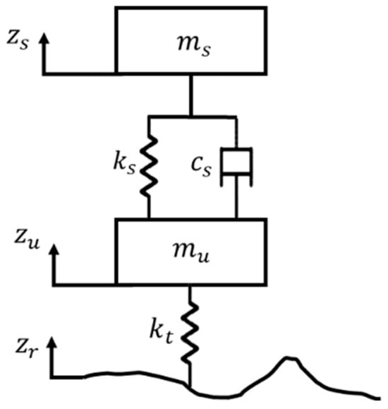
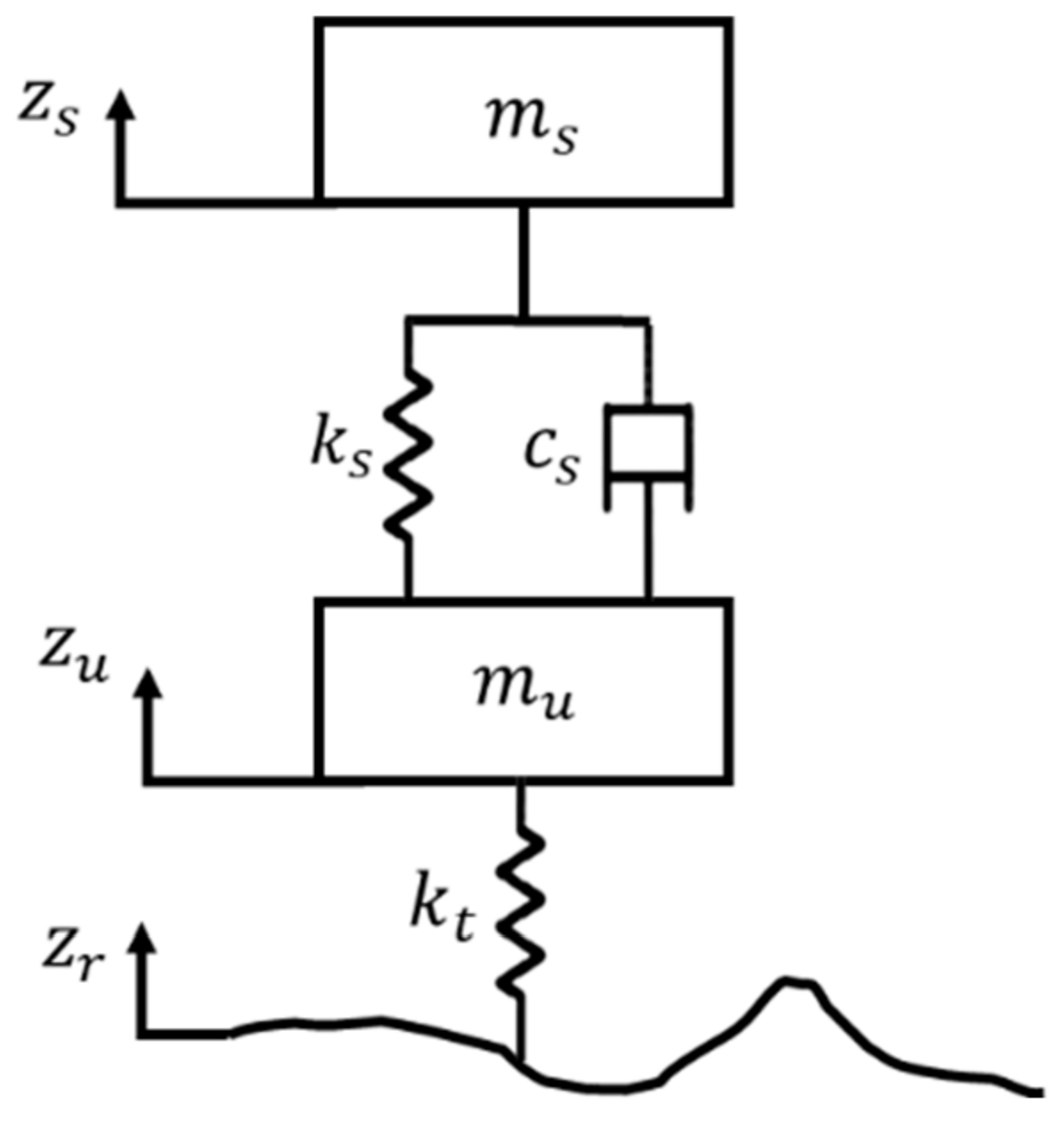
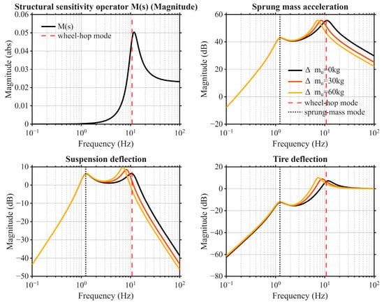
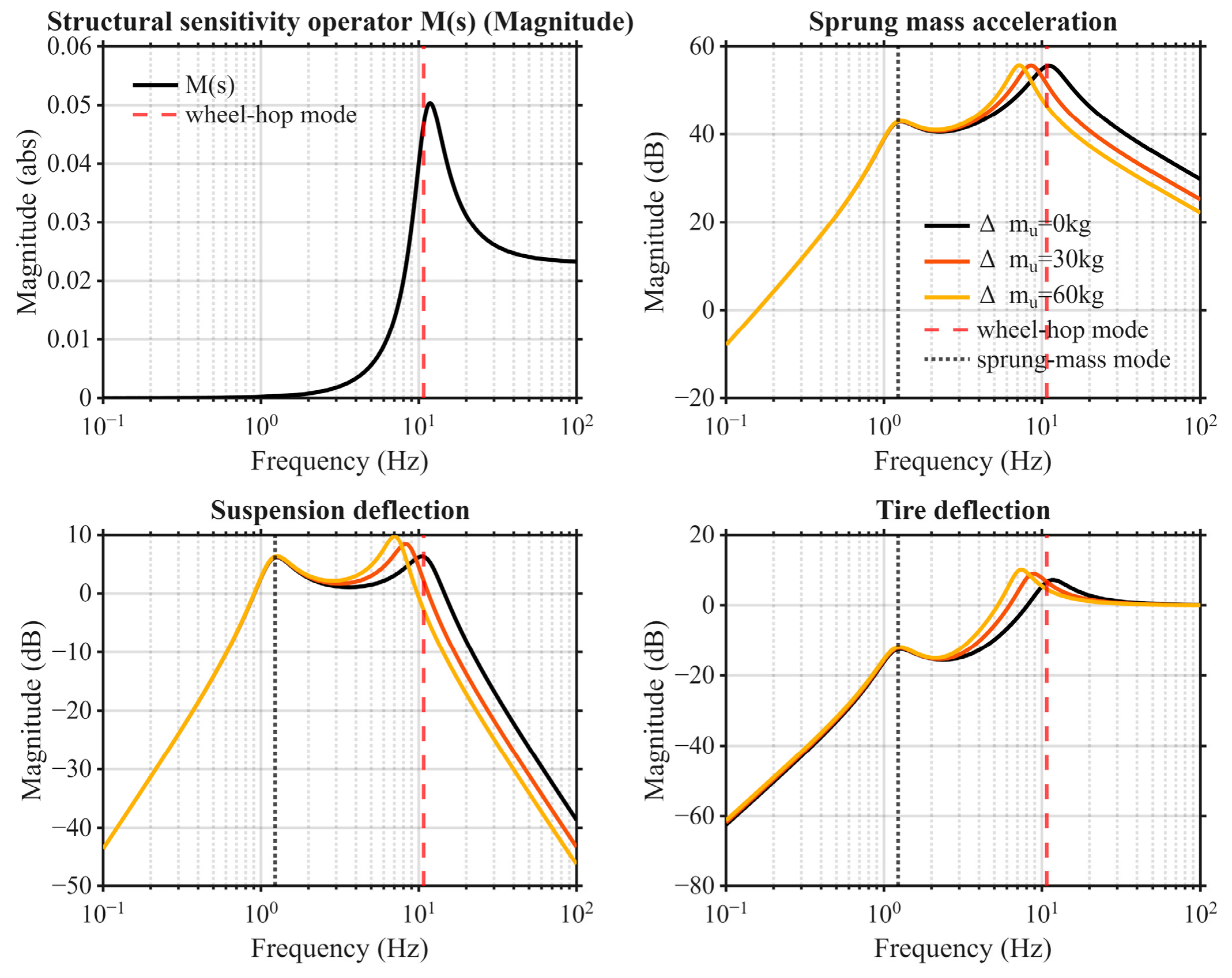
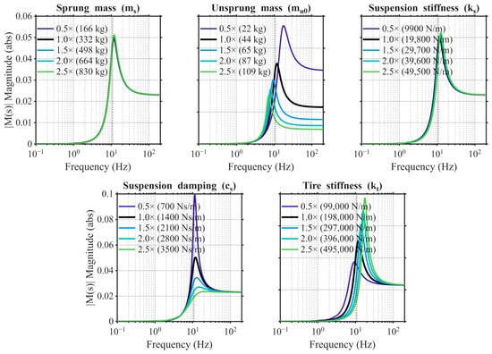
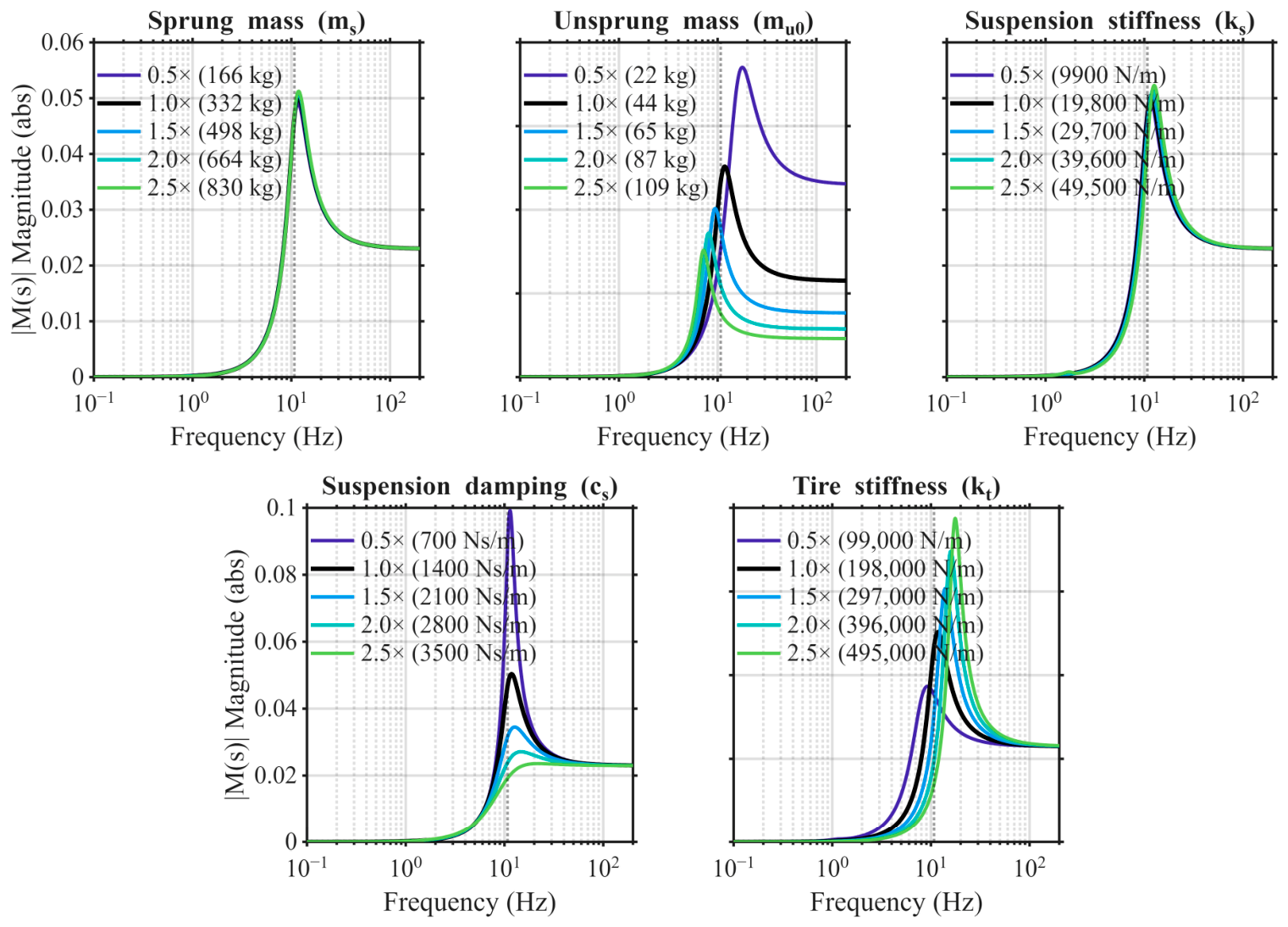
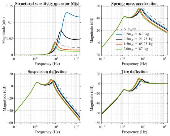
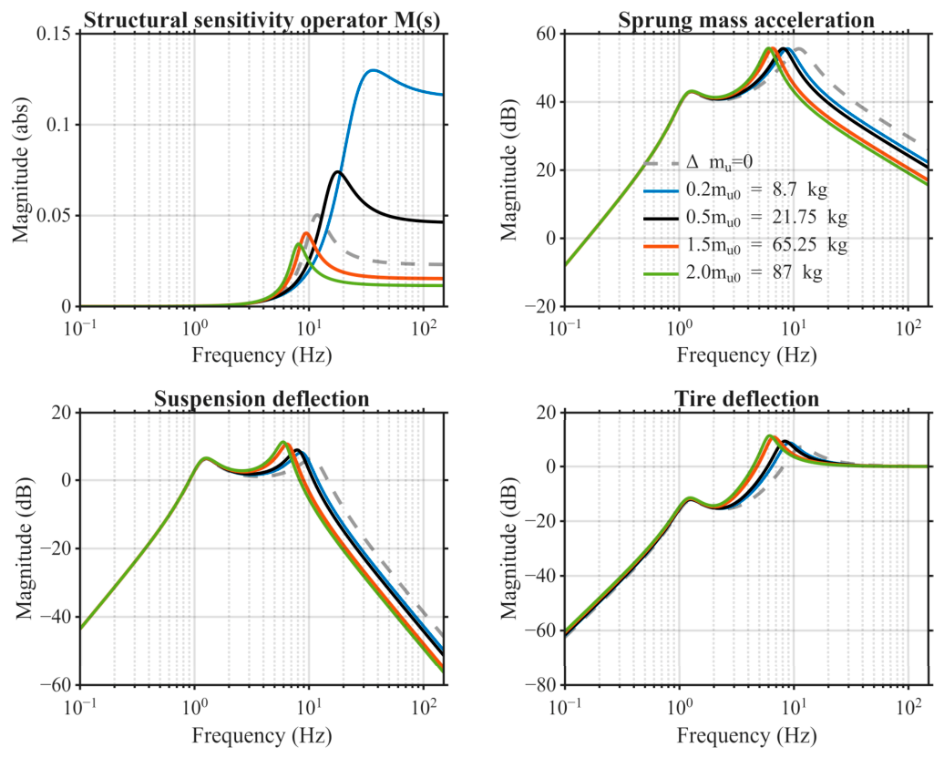
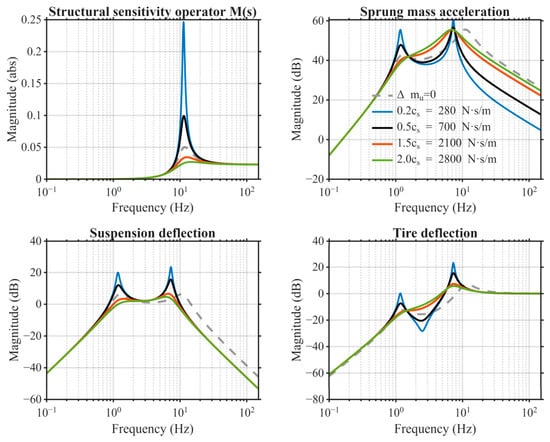

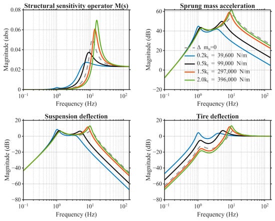
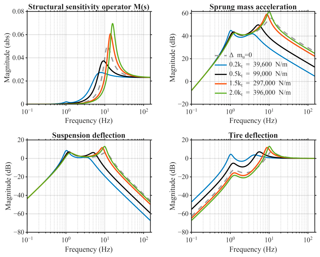
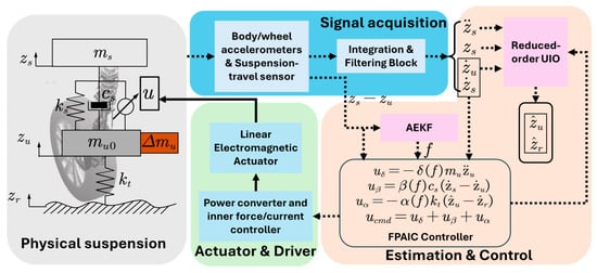
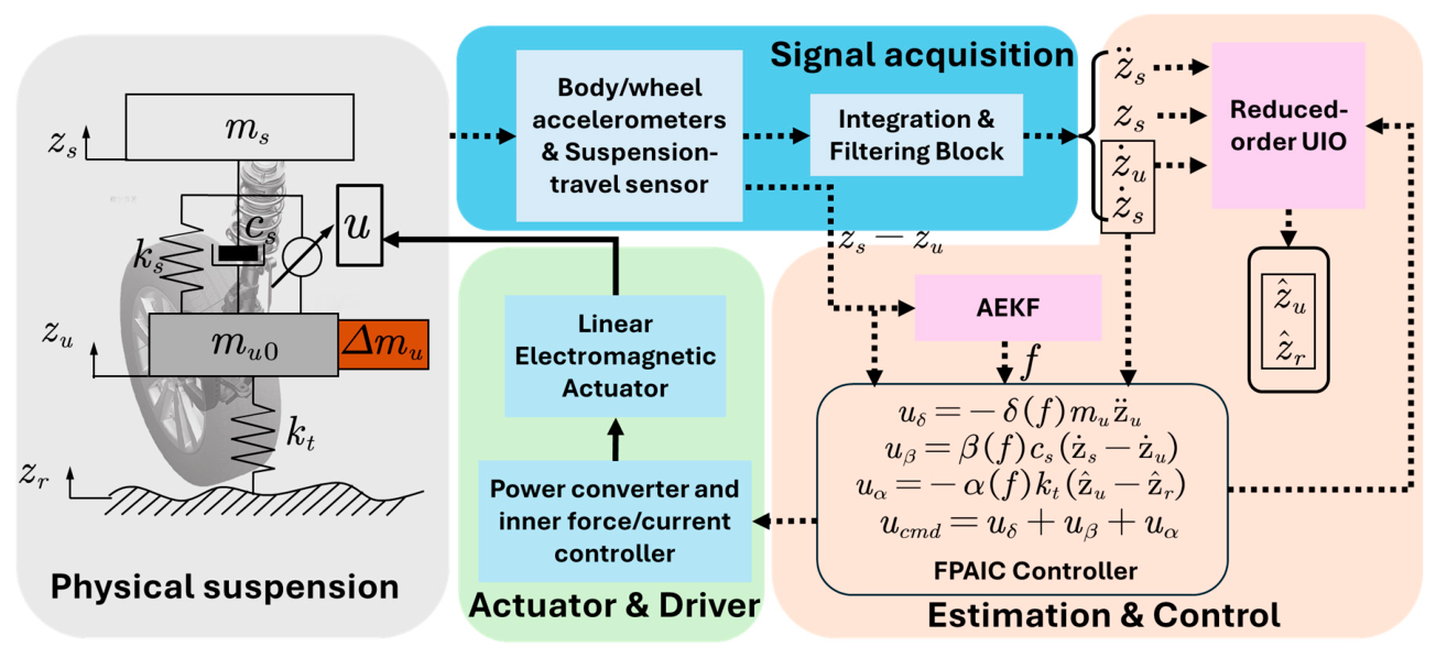
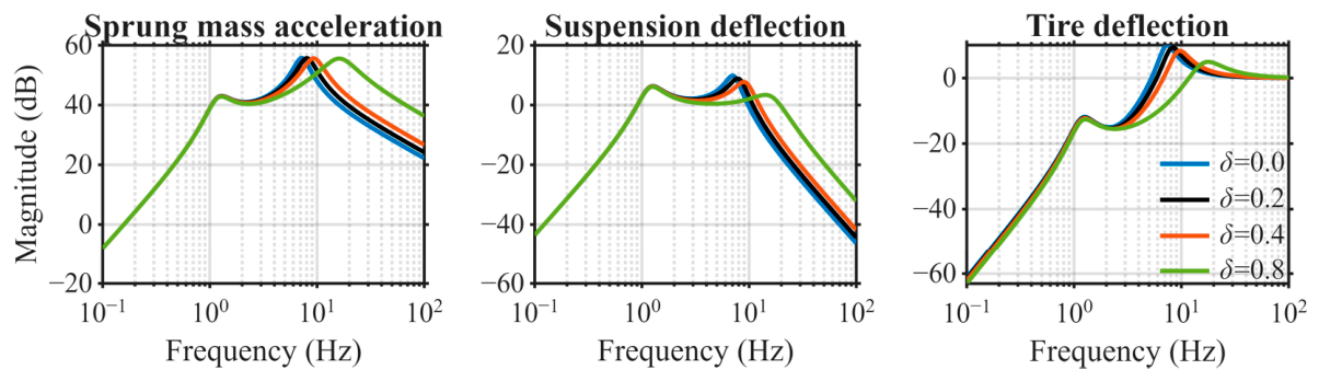
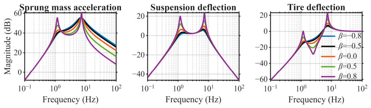
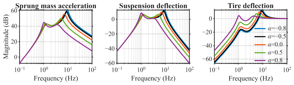
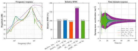
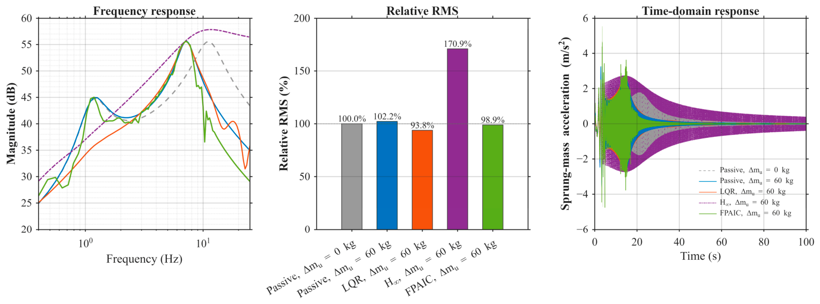
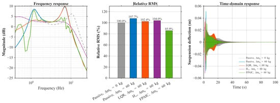
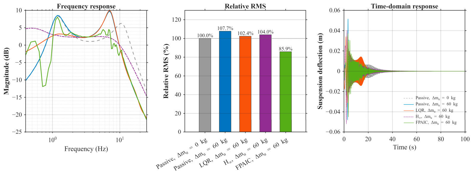
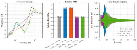
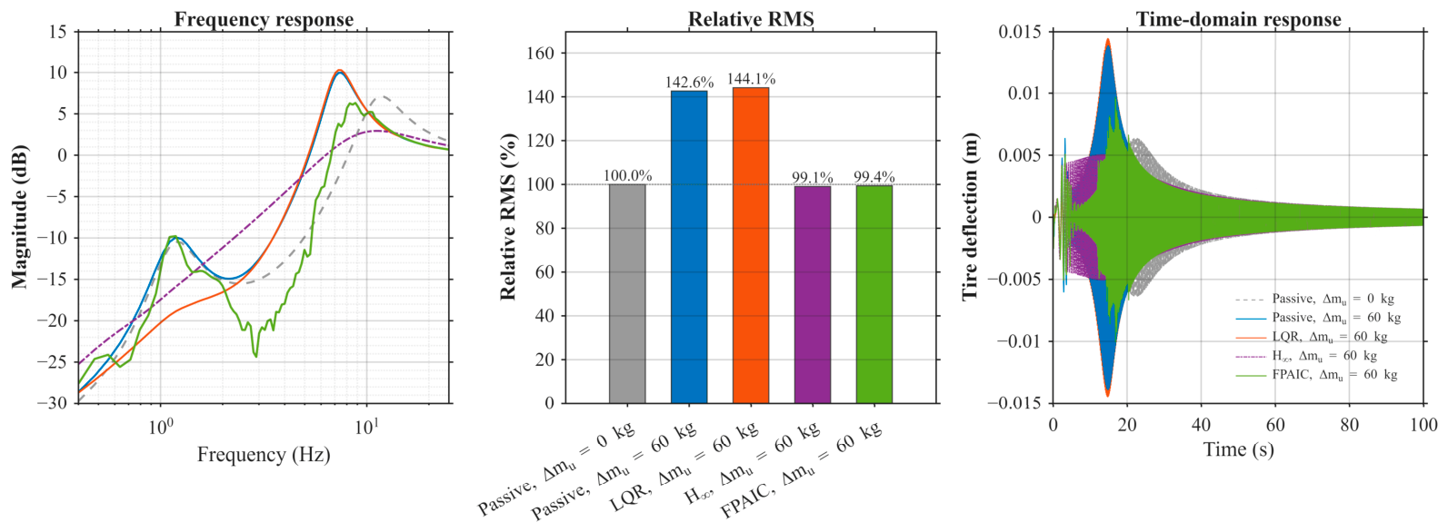
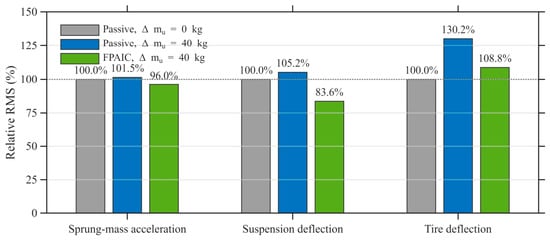
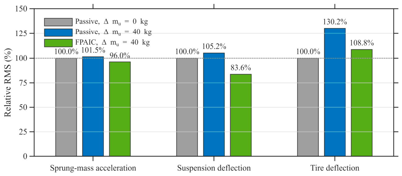
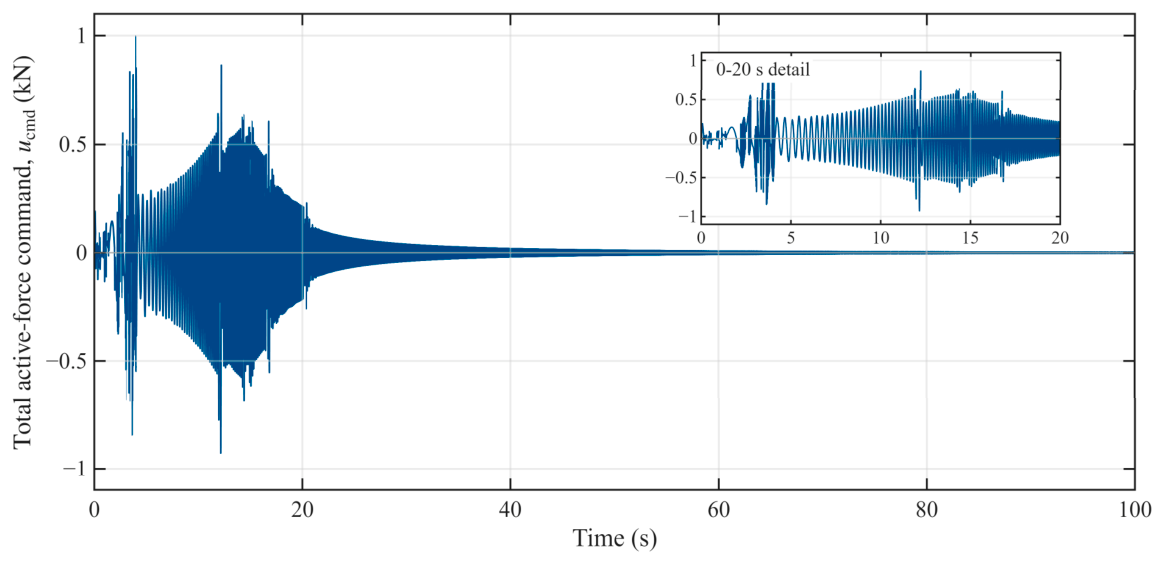

Disclaimer/Publisher’s Note: The statements, opinions and data contained in all publications are solely those of the individual author(s) and contributor(s) and not of MDPI and/or the editor(s). MDPI and/or the editor(s) disclaim responsibility for any injury to people or property resulting from any ideas, methods, instructions or products referred to in the content. |
© 2026 by the authors. Licensee MDPI, Basel, Switzerland. This article is an open access article distributed under the terms and conditions of the Creative Commons Attribution (CC BY) license.