


Abstract
With the increasing global elderly population and, naturally, mobility limitations, the number of people requiring walking aids is increasing. Research on robotic walking aids tends to focus on walkers, while robotic canes are usually designed for hospital or clinical use. Research into compact, low-cost robotic canes intended for use outside clinical environments remains limited. This work aims at designing a robotic cane with a deformable wheel and exploring its dynamics in a variety of terrains and small obstacles. A flexible wheel fabricated from thermoplastic polyurethane (TPU) material allows it to adapt to different surface profiles. The motion is controlled via a LQR controller. The prototype was tested in several real-world scenarios, with users without walking difficulties, and in rehabilitation scenarios, with users with mild locomotion difficulties. The flexible wheel proved capable of adapting to terrains with some irregularities while still providing support to the users. Furthermore, expert opinions suggest benefits in terms of musculoskeletal efforts.
1. Introduction
For most able-bodied individuals, walking is often regarded as a trivial activity, rarely warranting any thought, but for a significant portion of the global population, this is not the case. According to the United Nations (UN), the proportion of the total population over the age of 60 has been increasing, with a more pronounced growth since the beginning of the twenty-first century. Currently, the percentage of individuals over the age of 60 is 14.52%, and it is projected to rise to 16.47% by 2030 [1], with the total population over the age of 65 expected to reach around 2.5 billion by 2100, [2]. In 2011, 24% of adults over the age of 65 in the United States (US) reported using walking aids, more than in prior surveys [3]. Additionally, data from the National Health Interview Survey (NHIS) from 1980 to 1990 reveals that, across all age groups, the use of walking aids has increased [4].
Without assistance or mobility aids, difficulty walking can lead to increased isolation, anxiety, depression, and a general decline in quality of life [5]. Furthermore, both in the United States [6] and in Portugal [7,8], falls are the primary cause of accidental death by injury among individuals over the age of 65, highlighting the importance of using an adequate walking aid.
Poor surface handling, specifically of uneven surfaces, is a major cause of injury in wheeled walking aids, with 61.3% of accidents related to surface handling occurring when using wheelchairs or transport chairs, 34.7% when using walkers or rollators, and 4% when using canes [9].
Walking aids can be seen under multiple taxonomies. Within the types of devices, one can identify (i) robotic wheelchairs [10], (ii) robotic walkers and smart canes [11], and (iii) robotic wearables [12]. Within functional classes, multiple taxonomies have also been proposed in the literature. The device proposed in this work matches multiple classes, e.g., “walking support systems for the elderly” in [13], “walking assistance systems” in [14], or “mobility assistance devices” in [15]. The expression “smart cane” is commonly used for canes tailored for visually impaired people, as they are able to perceive obstacles in the neighbourhood. This project does not use environment perception features to adjust its behaviour. Instead, it is a robotised walking aid for people with limited mobility who may benefit from additional support when walking. The cane is able to adjust its behaviour from user inputs at the handle. It provides an alternative to smart walkers, which, while sturdy, are often heavy and cumbersome. Moreover, besides the use in clinical context, this type of cane can also be used in domestic scenarios, which are often cluttered, preventing the use of bulky devices.
The distinctive feature of this version of the robot cane is the use of a deformable wheel. The elastic properties of this wheel may be relevant to assist users in preserving their autonomy while lessening the musculoskeletal strain on the shoulder and elbow joints associated with a prolonged use of the cane [16]. Furthermore, the deformable wheel may simplify traversing a variety of terrains and climbing small objects often found in daily life, such as rugs or cables lying on the floor, while minimizing the propagation of vibrations and other disturbances through the cane handle.
The key contribution of the paper is the integrated design of a low-cost, low-weight, non-bulky cane that can be used in a wide variety of environments, including rough surfaces of the type found in domestic scenarios and in some common outdoor scenarios. This combination of features outperforms the state of the art, developing a stability feeling and having positive acceptance by real users. Furthermore, the specific combination of a soft wheel with a walking cane is a novel paradigm.
The organization of the paper is as follows. Relevant work from the literature is presented in Section 2 followed by implementation in Section 3, where the hardware is detailed. Note that aspects such as weight and cost strongly influence the dynamics of the cane and hence its acceptance. The control strategy, which determines how the cane behaves, is described in Section 4, and results of experiments are reviewed in Section 5. Conclusions are presented in Section 6.
2. State of the Art
Traditional walking canes are a widespread mobility aid that have been commonly used for centuries, but, while compact and convenient, they have a tendency to be less stable than more sturdy/robust walking aids, such as walkers, as they have a single contact point with the ground. More generally, robotic technologies can improve traditional mobility aids in areas such as fall detection and/or prevention [17], vital sign monitoring [18], and enhanced navigation, both autonomous and user controlled [19], and hence the combination of both is only natural.
Gait assistance in the context of canes, quad canes, and other types of walkers has been a topic of large discussion. For example, authors of [20] discussed the instrumentation of a cane on a treadmill to measure gait parameters in people under rehabilitation. In [21], the process of designing a cane for physical therapy was discussed, reporting recommendations for handle design with high usability and integrated instrumentation to provide feedback to the user. In [22], authors studied the design of the cane handle and showed it to influence weight shifting during walking and gait stability. Strategies to control the behaviour of the cane, other than the handle ergonomics, have also been proposed. For example, in [23], an haptic system was described to control a cane with a single wheel, with a unicycle kinematics similar to the one in this work. Furthermore, over the past five years, the field of robotic canes has accounted for just 18% of the research conducted in robotic walking aids, with 74% of the research focused on support frame-type robots and 8% on manipulator-type robots (see the survey in [24]).
A robotic cane can be highly convenient if manoeuvrability is adequate to human locomotion in common conditions. Most wheeled smart walking canes in development are heavy, expensive, and are only able to travel across smooth terrain, limiting their use to healthcare facilities.
A lightweight, minimally intrusive, and compact smart walking cane was developed in [25]. Weighing just 1.41 kg, the cane is significantly lighter than most current smart canes, allowing users to lift it easily without strain, which is ideal for frail people, as is often the case with elderly. It can also be used in environments where a healthcare supervisor may not be available.
The cane, which was built from an off-the-shelf traditional aluminium cane, has two force-sensing resistors (FSRs) on the handle that measures the force applied by the user, as well as an inertial measurement unit (IMU) that tracks the cane’s angle.
Based on the mathematical model of an inverted pendulum mounted on a unicycle, the controller of the wheel utilizes full-state feedback, with the corresponding gains obtained from a linear-quadratic regulator (LQR). This controller adjusts the rotation of the wheel based on the information obtained from the IMU and FSRs to provide the appropriate amount of support to the user while accounting for the locomotion gait.
The dynamical behaviour of the cane is greatly determined by the algorithm that commands the motorized degrees of freedom. A sliding mode control is proposed in [26] to control the angle of a robot cane, building upon the smart cane in [25]. The variation in [27] proposes (i) a gain-scheduling controller to choose, at each moment, the adequate linearised model, and (ii) use of the Gini sparsity index to adjust the control gains. Each of these control methods leads to usage with different learning curves and is preferred by different users (note that the perception of safety is often influenced by a diversity of factors, sometimes subjective, e.g., cultural factors; see, for instance, [28] for a broad view). For the purpose of this work, the simplest version is used, as the main goal is to test a deformable wheel. The version in [25], with which shares several physical characteristics, serves as baseline both for acceptance comparison and development of the current prototype.
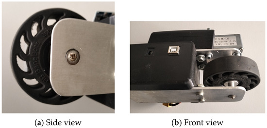
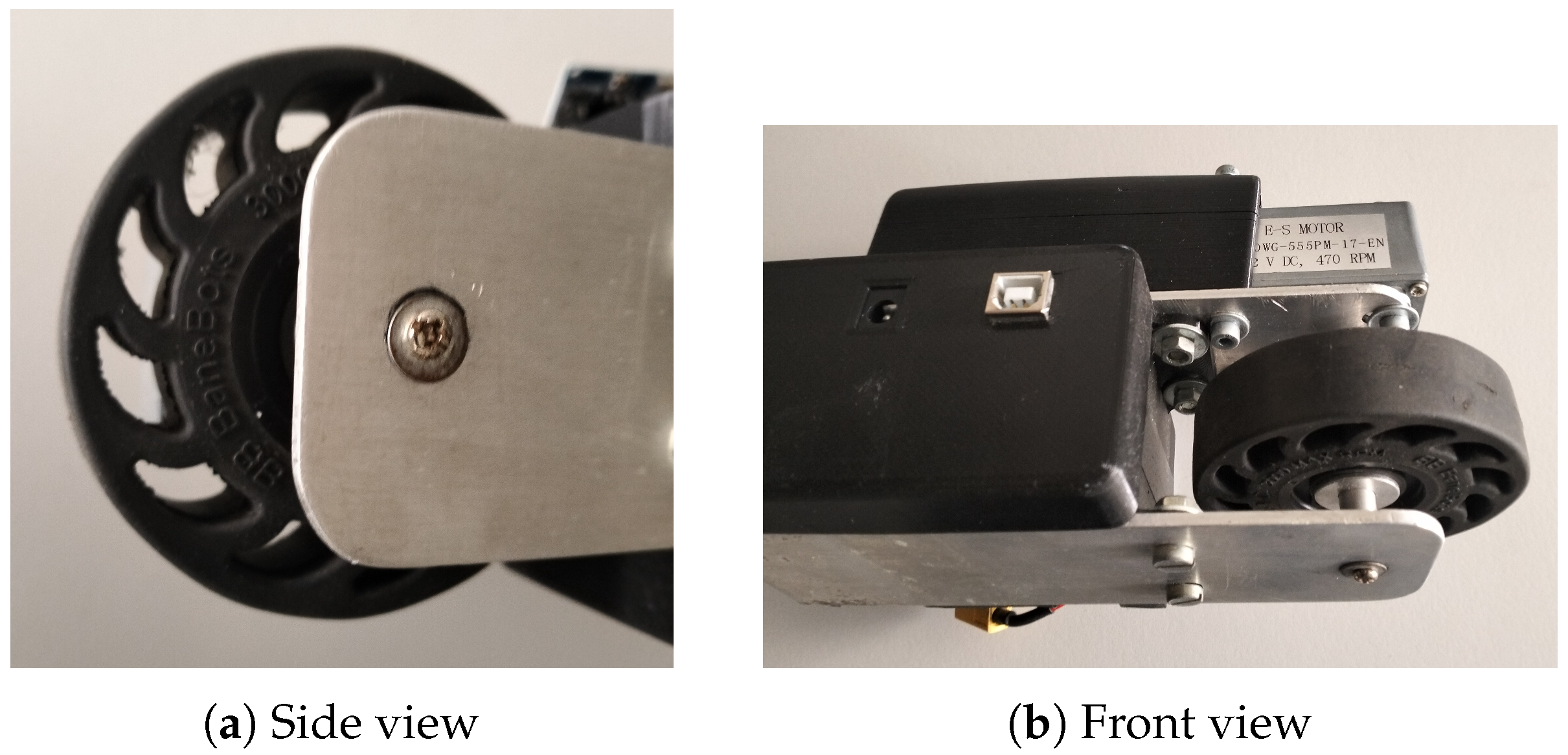
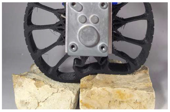
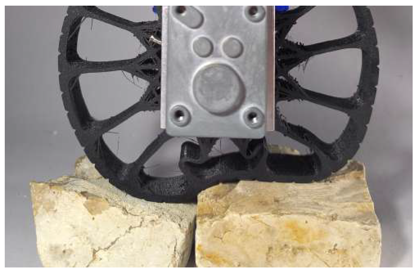
Off-the-shelf available deformable wheels represent an entry point into this domain. Figure 1 shows an early version of the cane with rubber based deformable wheel. However, the elastic properties were not suitable for rehabilitation purposes and the turnaround time to develop suitable versions was much higher than the 3D printing solution.
Figure 1.
Two views of an off-the-shelf deformable wheel mounted on a cane (the spokes that define the elastic properties of the wheel are clearly visible).
Multiple compliant wheels capable of moving on difficult surfaces have been proposed in the literature. These are mostly oriented to generic mobile robots, though there are references to advantages of deformable wheels, e.g., crawlers, in the context of walker robots for rehabilitation, namely requiring less muscle strength by the users [29]. Among the variety of designs, in [30], a wheel-leg combo formed by a regular wheel and external elastic elements is described. Still using a rigid wheel, in [31], a compliance mechanism was added to support the wheel akin to a suspension. In [32], a radial structure of linear springs connecting foot pads was proposed, akin to a wheel with a deformable boundary. An origami inspired deformable wheel is described in [33], targeting mobile platforms.
Designed to be able to assist robots navigating challenging terrain, the PaTS-Wheel in [34] has the climbing ability of wheel-legs (whegs) hybrid structures with the efficiency of regular wheels. Through the use of compliant mechanisms, it is able to adapt to uneven surfaces and overcome obstacles without the need for additional hardware or software.
Manufactured from TPU, this wheel is made out of four mechanisms known as motion reversing linkages that are arranged around the central hub. Each linkage consists of two four-bar linkages (the “pad” and the “claw”) that are connected by a coupler that functions as a lever around a central pivot point, inverting the motion from the pad. When compressed, the pad pushes the claw outward to hook and climb over obstacles. This passive transformation allows easy integration with any wheeled robot.
The PaTS-Wheel can overcome obstacles up to 70% of its diameter, compared to 25% for a standard wheel and 61% for a wheg. The energy consumption is similar for all three wheel types when overcoming smaller obstacles. For obstacles between 16% and 25% of the wheel’s diameter, the energy consumption increases for the PaTS-Wheel and standard wheel but remains unchanged for the wheg. For obstacles higher than 25%, the energy consumption of the wheg increases but remains lower than that of the PaTS-Wheel.
Two non-pneumatic tire (NPT) designs were proposed in [35], Tweel-2, an optimization of Michelin’s commercial Tweel, and the Saddle, which has hyperbolic paraboloid spokes inspired by the forelimb of a mantis shrimp. The vertical bearing capacity of each model was evaluated, with a version with saddle spokes showing the highest elastic modulus, twice that of the honeycomb spokes. They also exhibit the highest yield strength and energy absorption, are four times stronger, and absorb 3.8 times more energy than the Tweel, which has the lowest values in both metrics. For all the wheel designs tested, increased compression leads to greater strain on the load-bearing spokes. The three central spokes carry about 70% of the strain energy, while other spokes and outer threads store less than 15%. While the Honeycomb, Tweel, and Tweel-2 show significant stress concentrations at bending points, the saddle spokes distribute pressure more evenly, minimizing stress concentrations. Tweel-2 improves on the original by adding a concentric ring across the middle of its spokes. This ring helps the spokes bend more uniformly, reducing stress concentrations and increasing energy absorption by over 40%.
The literature review above, though pointing to innovations in wheel design, among other aspects, may not comply with the objectives of this work. Mechanical complexity, such as that in these wheel systems, tends to result in added weight and volume that are incompatible with a cane for real users, which must be lightweight, of reduced maintenance, robust, and small volume.
As aforementioned, this work differs from the state of the art as it presents an integrated system targeting the domain of assistive devices and, in addition, the device is successfully demonstrated with users from the target domain. Even studies in alleged clinical settings, e.g., in [36], were made with the users walking in a treadmill, at 0.8 m/s, velocity much higher than that used in common rehabilitation conditions. The deformable wheel paradigm covered in this paper addresses the niche of consumer-grade smart canes intended for everyday use that are suited for moderately uneven terrain.
3. Prototype Implementation Aspects
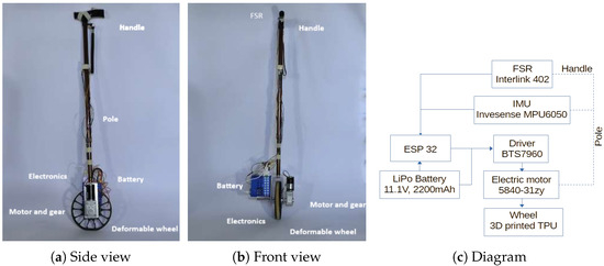
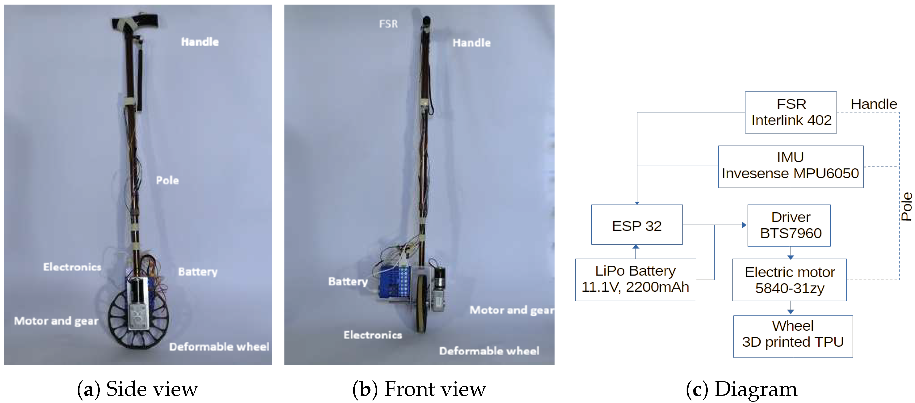
The body of the cane is made out of a standard aluminium cane attached to an aluminium frame which holds the motor, the electronics, and the wheel (see Figure 2).
Figure 2.
Prototype cane. The total mass is approximately 1.3 kg.
A Keyestudio MPU6050 unit, from Keyes DIY Robot Co., Ltd, Shenzhen, China, is used to estimate the angle of the cane. This unit captures accelerometer and rate-gyro data, as well as temperature (not used in this prototype). The angle with the vertical is obtained from the accelerometer and rate-gyro data, combined in a Kalman filter. The angle is first estimated by integrating the rate-gyro angular velocity. This estimate is then corrected using the accelerometer data.
The incidence of essential tremors tends to increase with age [37], as does the use of canes. Essential tremor is the most common neurological cause of postural or action tremor, usually presenting as a tremor of 6 to 12 Hz [38]. Another common cause of tremors, particularly in the hands, is Parkinson’s disease, which typically produces tremors of 4 to 7 Hz [39]. To reduce the effect of tremors in the angle measurement from the Kalman filter, a low-pass filter is used, namely,
with as the smoothing factor. This takes the current estimate of the angle from the Kalman filter, , and the previously smoothed angle value, , producing the current filtered angle, .
For a cutoff frequency ,
with as the sampling period. This yields , which provides a good tradeoff between smoothing and responsiveness for this prototype.
The MPU6050 can be configured with a digital low-pass filter at cutoff values (5, 10, 21, 44, 94, or 184 Hz). However, this filter operates on raw sensor data, prior to any angle calculations. We opted to set the internal filter to 21 Hz, where it can filter some higher frequency noise during data acquisition, and then applied the above low-pass filter, after the Kalman filter. This approach provides full control over the cutoff frequency while preserving lower frequency data before the angles are calculated.
A NodeMCU ESP32 microcontroller, from SIMAC Electronics GmbH, Neukirchen-Vluyn, Germany, is used as computational device to run the control algorithm. Its 240 MHz dual-core processor allows for fast handling of the control loop and filtering. Moreover, the ESP32 has built-in Bluetooth capability, allowing for a communication channel with remote laptop that can be used for additional processing, e.g., gait analysis, if necessary. Furthermore, the 32 GPIO pins allow for an easy integration of additional sensors in future upgrades.
Two different motors were considered, from Shenzhen Weiheng Transmission Technology Co., Ltd, Shenzhen, China. One was a model 5840-555 motor, which, although it has a maximum speed of 470 rpm, has a low torque and stalls immediately when weight is applied to the cane.
The other motor considered was a 5840-31zy, with a maximum speed of 160 rpm. This motor provided slightly higher torque but was considerably slower, and although it could handle more weight than the previously mentioned motor, it still stalled under relatively small loads (values typically generated by people feeling unsteady).
The reduced power from the motors is, in general, considered as a limitation and it ultimately might have limited the performance of the prototype throughout the tests. However, it is worth noting that it can also be considered as a passive safety feature, for instance, avoiding dangerous runaways when users are pressing the cane (and likely in a critical stability situation). Additionally, the coupling between the motor and the wheel is made through a high-ratio gearbox, which also acts as a passive safety feature, which in case of sudden loss of power makes it very difficult for the wheel to rotate. Also, software watchdogs monitor the output of the controller and remove any abnormal values. Furthermore, it is worth noting that the specific application envisaged has an implicit tradeoff between cost and weight, i.e., the cane must be very low-cost and the weight must be as low as possible. Hence basic, off-the-shelf, low-power and weight, motors are the natural choice.
Two drivers were considered: the L298N dual H-bridge, from ST Microeletronics, and the BTS7960 high-current H-bridge, from Infineon Technologies AG. The L298N driver has a peak current output of 2 A, which may not be enough and prevent the motors from generating the necessary torque to move the cane under load. The BTS7960 has a significantly higher current output level, with a peak output of 43 A, enough for the current motor and was the selected driver.
The motor and motor driver are powered by a Gens ace Soaring Mini lithium polymer (LiPo) battery, with a capacity of 2200 mAh and a voltage output of 11.1 V.
The microcontroller is powered by an off-the-shelf power bank at 5 V and 2000 mAh. This setup ensures that the voltage requirements of both components are met, preventing the risk of underpowering the motor and avoiding brown-out conditions in the microcontroller.
To measure the force applied to the handle of the cane, we used an Interlink 402 force-sensitive resistor (FSR), from Interlink Electronics, Freemont, CA, USA. This is a variable resistor whose resistance decreases as the applied force increases. On average, cane users support approximately 7 to 10% of their body weight with the cane [40]. Based on this, the FSR measurement range was set to be up to 10 kg.
Calibration was performed using a testing rig that distributes force evenly across the FSR. Known weights were applied to the platform and the ADC values read by the ESP32 were recorded. The conversion from the ADC raw values, x, to grams, , was performed as follows,
The wheel is 3D printed, from TPU, with a Shore hardness of 95A. Empirical selection and several prototypes confirmed the adequacy of the material. TPU is a cost-effective common flexible 3D printing filament which exhibits characteristics of both plastics and rubbers. It combines high elasticity with strong abrasion resistance, making it well suited for applications that require repeated deformation under load, such as a deformable wheel. Additionally, 3D printing allows for fast and inexpensive prototyping. While 95A Shore hardness TPU it is not as malleable as other elastomers, it is widely available and easier to print compared to softer TPU filaments. Furthermore, the effective stiffness of the printed wheels can be determined by their geometry and the print settings chosen in the slicer software.
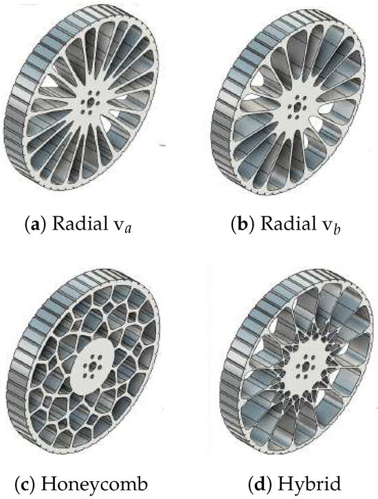
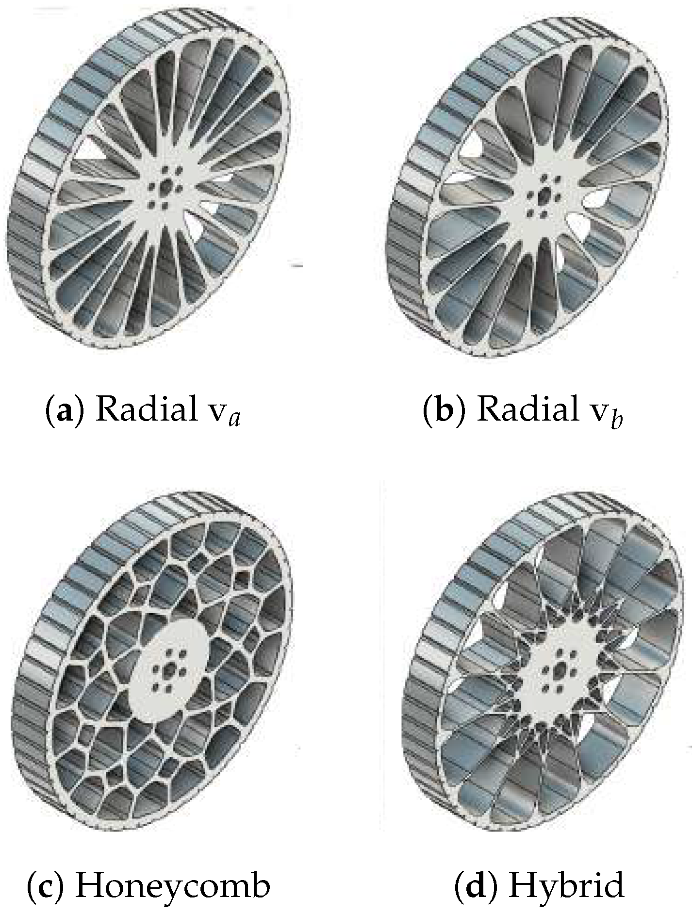
The spoke geometry on a flexible NPT determines the wheel’s deformation characteristics. Unlike rigid wheels, where spoke geometry has minimal influence on compliance, the NPT spoke design directly affects both stiffness and damping. Four wheel designs were tested: one honeycomb, radial, differing in the number of spokes, and one hybrid, combining radial and angled spokes (see Figure 3).
Figure 3.
Four versions, of different stiffness, of the deformable wheel (radial vb with fewer spokes than va).
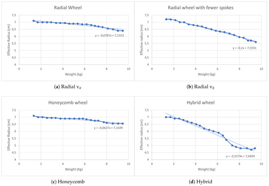
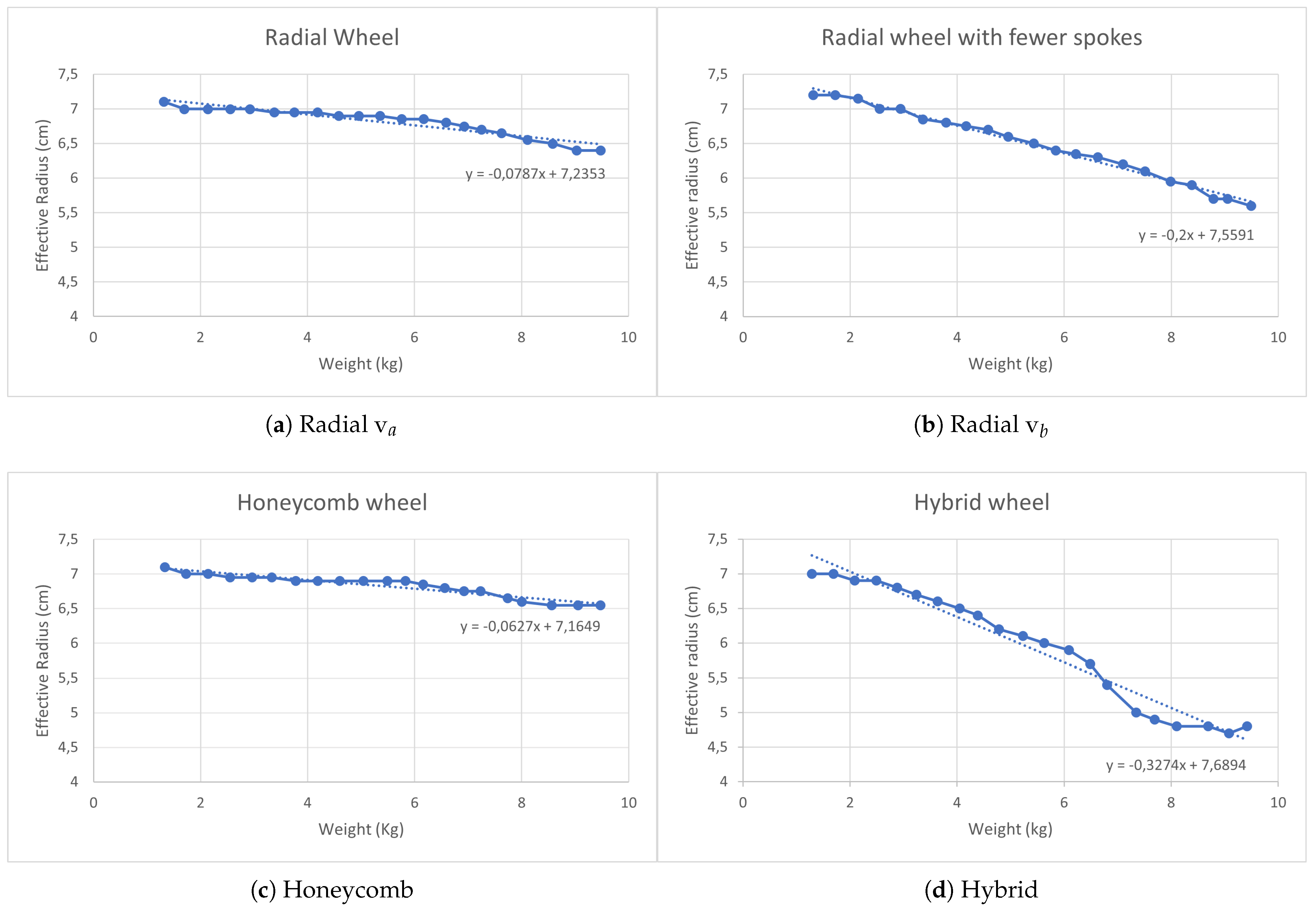
Each configuration redistributes loads differently, creating distinct deformation profiles under vertical loads. These designs were chosen based on their ease of printing and expected compliance (see Figure 4).
Figure 4.
Deformation of the wheels.
Vertical compliance is a key property of flexible NPTs for this application. On uneven terrain, a vertically compliant wheel acts as a mechanical filter, absorbing shocks before they reach the cane handle and reducing the forces transmitted to the user. The load-deformation curve, determined by both the material and the spoke geometry, dictates how shocks are absorbed. A good deformable wheel can attenuate vertical impacts without reaching its full compression limit, maintaining sufficient stiffness to support the user’s body weight. Furthermore, any lateral deformation must be minimized to preserve lateral stability.
The vertical compliance of a NPT affects the contact patch between the wheel and the ground (see Figure 5). As the wheel deforms vertically, the contact patch increases, distributing the load more evenly across the surface, reducing ground pressure, and improving the traction compared to rigid wheels, which maintain a smaller, more consistent contact patch.
Figure 5.
Deformable wheel under extreme load.
Furthermore, the ability of a tire to conform its tread to the terrain enhances stability when moving over uneven surfaces or small obstacles. This adaptability is particularly important in assistive devices, where unstable support can compromise user safety.
4. Controller
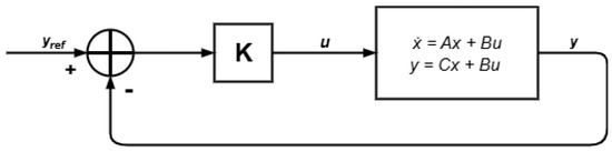
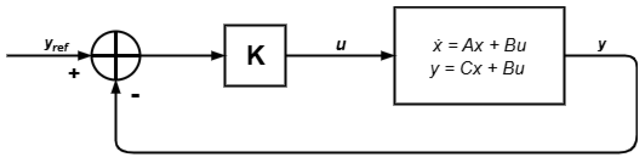
The mathematical model, linearisation, and control structure used in this prototype were similar to [25] (see Figure 6), with the adequate reparameterization. The model was linearised around the upright position as the usual gait cycle (for a normal can) is an oscillating movement in the vertical/sagittal plane. Since the physical principles of both prototypes are similar (a unicycle-type cane with a single actuated wheel), the same model and LQR controller approach was adopted. Although the structure and weight distribution of both prototypes differ slightly, the actuation principle remains unchanged, with a single motor with rotation axis perpendicular to the sagittal plane.
Figure 6.
Block diagram of the cane model with full-state feedback LQR controller.
During a normal gait cycle, the cane is controlled to oscillate between approximately and (angles to the vertical). However, the control system cannot maintain equilibrium at this reference angle (this would require aggressive movements inappropriate for the application). From an initial position of and a reference angle of , the system overshoots, reaching , then stabilizing at instead of the expected . During this process, the system briefly crosses the reference angle.
In the physical prototype, the power to the motor is cut when the angle reaches , blocking the motion and allowing the user to support their weight on the cane, and it is switched back on when the angle enters the admissible range. This workaround allows for the testing with real users despite the limitations imposed by the single control variable in the cane and the sub-optimal control method. The motor cuttof is a strong safety feature that is absolutely necessary if the device is to be tested in the real world (explaining to users the objectives of the study and that no safety problems is expected is part of the informed consent). It is worth to note that no switching between dynamic models occurs at this point, i.e., the structure of the model does not vary, and during the power cutoff the state of the system is kept in a close neighbourhood of a fixed state. Therefore, this workaround does not risk inducing stability problems, as it can happen in generic switched linear systems.
An LQR is an optimal control method which provides a systematic way to determine feedback gains for linear systems. The mathematical model of the cane is akin to an inverted pendulum on a cart, hence the rationale for the LQR control (see (4) or [27] for further details).
where x and stand for the state variables, and are the masses of the wheel and cane, respectively, r is the radius of the wheel, l is the length of the rod, is a viscous friction coefficient, and u is the motor input voltage.
The control law is , with x the state vector and K a gain matrix. The matrix K is obtained by minimizing the quadratic cost
with the weighting matrices Q and R defining the trade-off between state error and control effort. Higher values of Q increase the controller’s sensitivity to state deviations (in this case, deviation from the reference angle of ), leading to faster stabilization. Larger values of R penalize large control inputs, resulting in a smoother motor response.
Matrix Q was set to the value in [25],
The R matrix, however, was adjusted empirically to tune the response of the current physical prototype. Each adjustment was judged in terms of stabilization speed and smoothness of the motion. The goal was to achieve a tradeoff between the time taken to reach the reference angle and user comfort, prioritizing the latter to ensure a smoother operation.
The jitter in the motion of each motor felt played a significant role in selecting R. For lower-speed motors, the controller can behave aggressively while maintaining smooth operation. Therefore, was chosen for these two motors. For the higher-speed motor, an aggressive control caused a jittery motion so a higher R was chosen in order to reduce control effort and ensure a smoother response .
The LQR gain matrix, K, was then computed using the lqr function in Octave, based on Q and R. For the motor with the lower maximum speed and a lower value of R, the resulting gain matrix was
The motor with the higher R yielded lower values for the gain matrix and led to a less aggressive behaviour, with the corresponding gains set to
The LQR controller was originally designed for a four-state system represented by , where x is the position and is the tilt angle of the cane. In this prototype, only the tilt angle and the cane’s angular velocity were measured using the IMU. Consequently, only the third and fourth components of the full-state gain matrix, those associated with the angle and its rate of change, were used in the final control algorithm. This means that the controller’s feedback law depends uniquely on angular dynamics,
The system has a single control variable, i.e., the voltage applied to the motor, and hence it is impossible to control both the linear velocity of the centre of the wheel (matching the walking gait linear velocity) and the angle of the cane with the vertical position. However, the typical walking gait involves a tradeoff between the variation of the cane angle and the linear velocity, and hence the control acts only on the cane angle. Moreover, perturbing and around the optimal values influences the reaction of the cane to deviations from the vertical line and hence affects the linear velocity of the centre of the wheel. Furthermore, the gains were found suitable to all the users tested, yielding a positive acceptance.
The changes to the original controller are functional adjustments, namely parameter and controller references tuning, and do not alter the underlying LQR design.
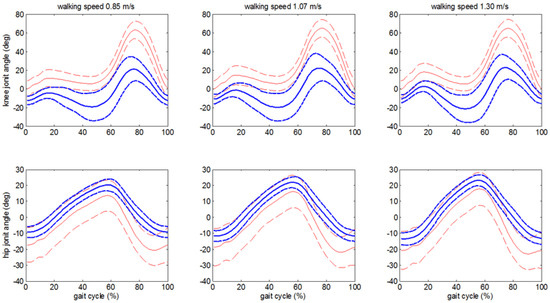
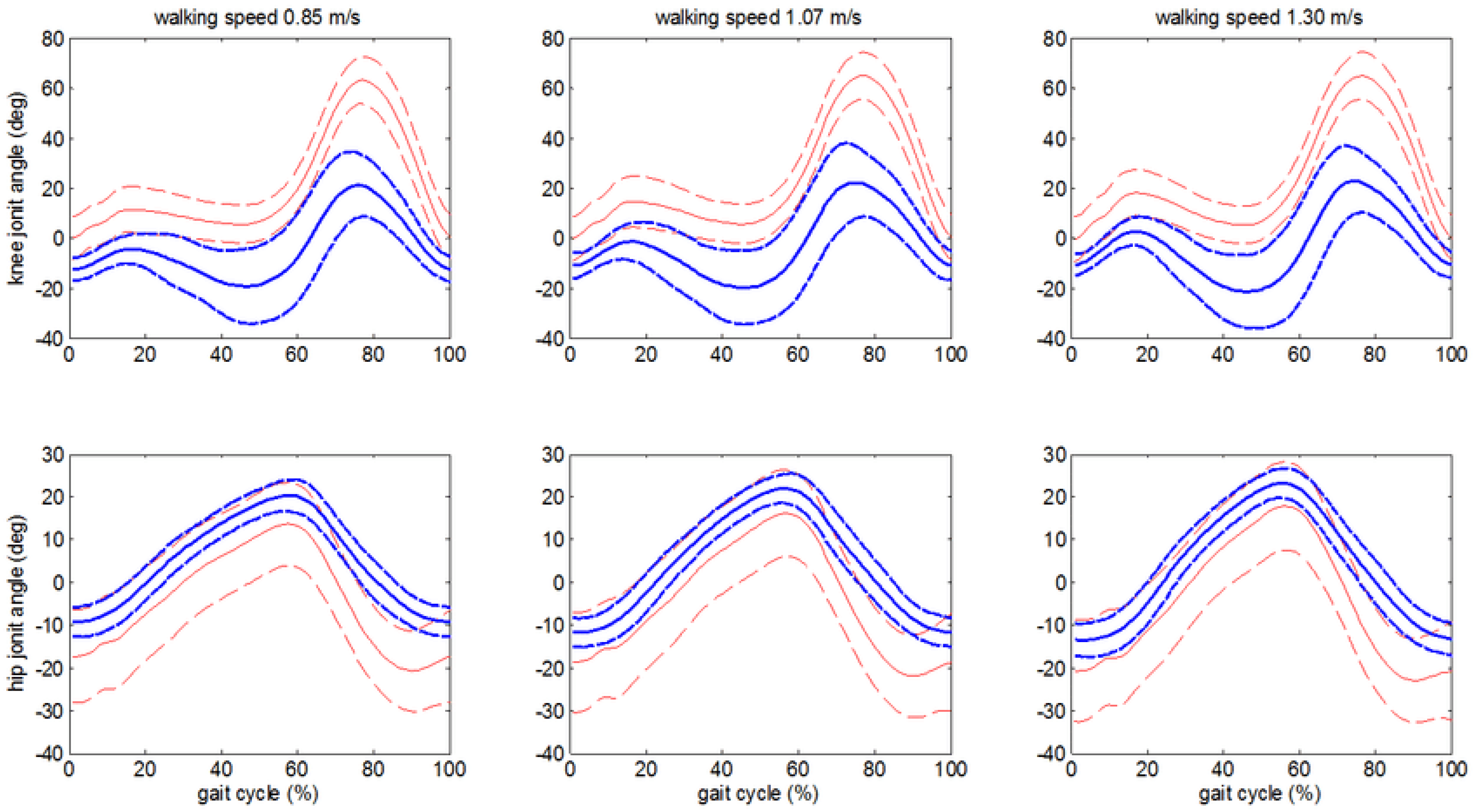
In the normal usage, a cane should be swung forward when the contralateral leg is in its swing phase. The cane should land approximately in line with the weaker or injured leg to provide support during its stance phase. Hip joint angles during a gait cycle vary with walking speed. For a healthy adult walking at a regular pace of 1.3 m/s, the hip joint swings from approximately to slightly over . For an adult walking moderately slowly, at a pace of 0.85 m/s, this range reduces to slightly below to (see Figure 7). Cane users typically walk slower than the previously mentioned speeds. Following [41], on average, cane users tend to walk with a speed close to 0.41 m/s. Therefore, their hip joint angles are expected to have smaller amplitudes than those in Figure 7.
Figure 7.
Knee and hip joint angles over a gait cycle at different walking speeds (from [42], the thick lines indicate joint angles obtained with a Kinect sensor, the thin lines indicate joint angles obtained with a motion tracking system, and the dashed lines bound a one standard deviation wide region ).
However, cane users typically do not use their cane in line with their hip joint. In order to increase their support polygon, users often place the cane in front of their body. Using the original LQR controller as a baseline, a lower limit of and an upper limit of for the cane tilt were selected. This upper limit was chosen as the new reference for the LQR controller. In order to replicate the behaviour of a traditional cane, when the prototype reaches , the microcontroller disables the motor, allowing the user to safely complete the swing phase of their stronger leg. Once the cane reaches , the motor is reactivated, allowing the cane to return to the reference angle. These threshold angles are general guidelines and may require adjustment to match the individual user and their gait pattern.
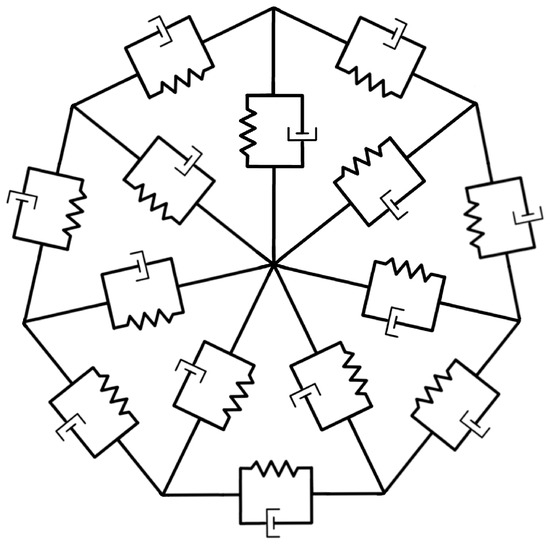
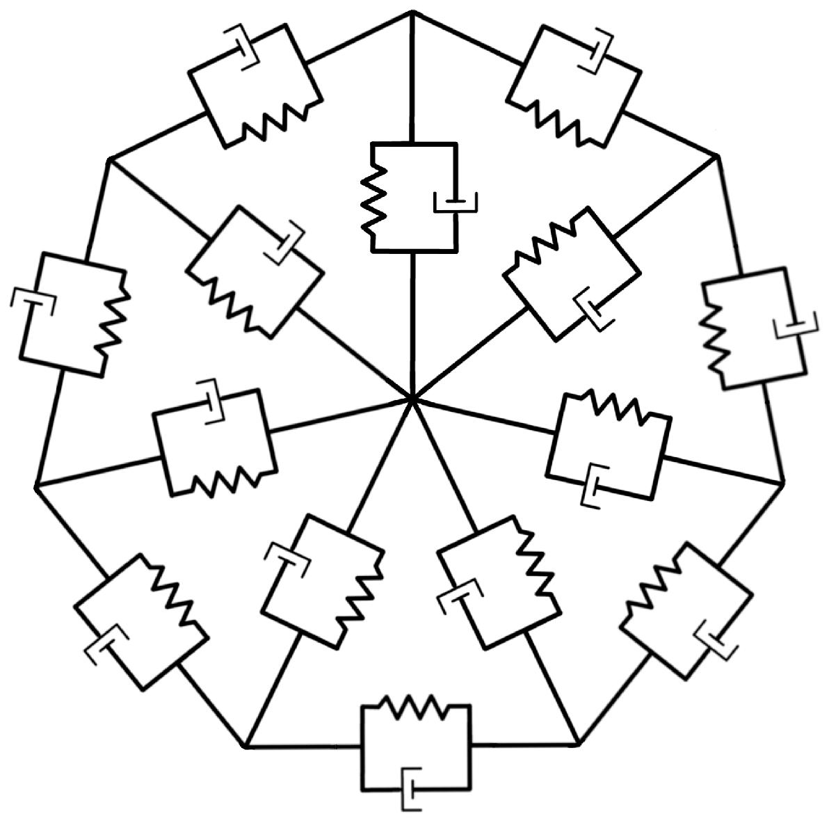
Due to the flexibility of the NPTs, the rim and each spoke behave as a local spring-damper element (see Figure 8). This can be verified by the near linear deflection of the printed wheels seen in Figure 4. The wheel can therefore be modelled as a series of radial spring-damper systems (see Figure 8).
Figure 8.
Spring-damper wheel simplification.
In this system, the springs represent the elastic deformation of the rim and spokes, while the dampers account for energy dissipation due to hysteresis. This compliance indicates that our wheels do not behave as perfectly rigid elements, which is an assumption of the unicycle model in [25]. However, due to the limitations in the available power, the current motor is not able to drive the wheel if it is significantly deformed, so the rigid wheel assumption in the linearised model remains valid. Note that, besides the cost factor, a stronger model would likely be able to drive the wheel to overcome a wider class of obstacles, though at the expense of increasing the risk of inducing gait instabilities.
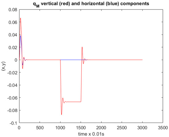
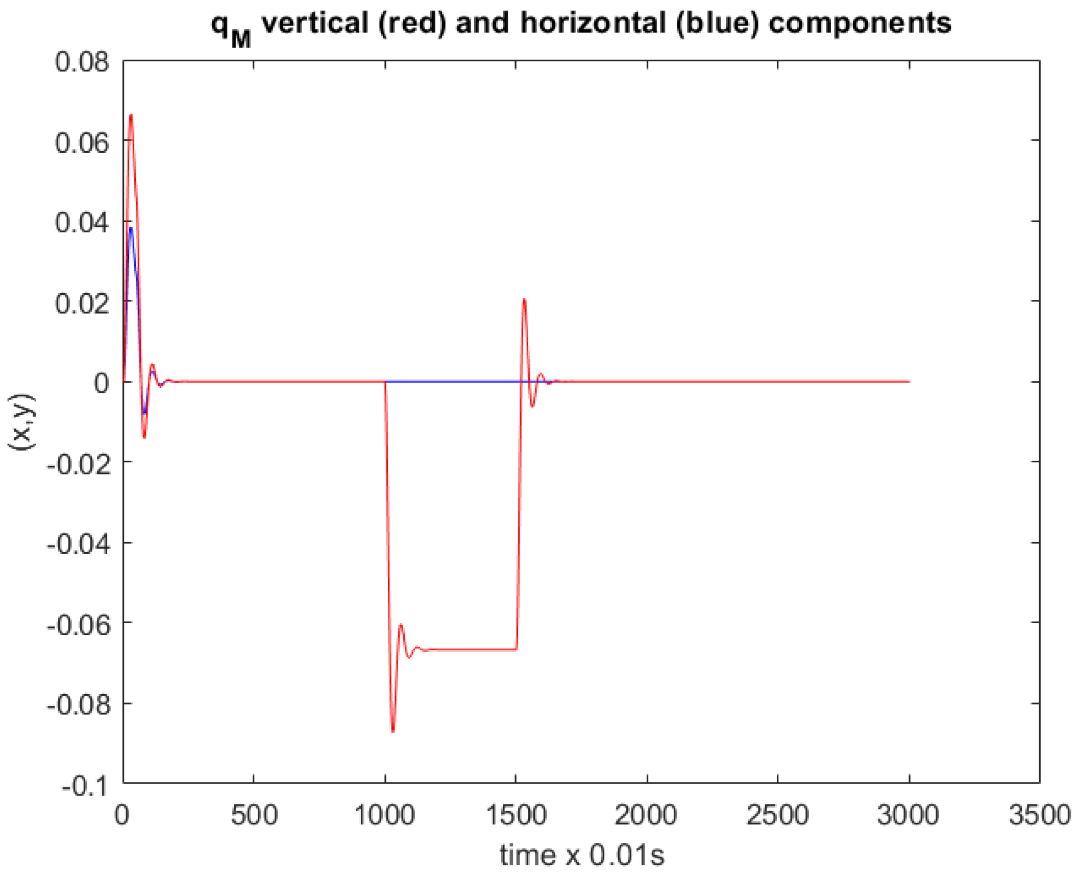
Note that from the point of view of the user who grabs the cane at the handle, the distinctive feature is absorbing/damping dynamics, which may be felt in their own body. To illustrate the dynamics of the wheel, we consider a simplified version with three identical spokes (far less than the prototype wheels considered but allowing a more intuitive visualization of the dynamics), , and a mass equivalent to that of the current version of the cane, Kg. Figure 9 shows the behaviour of the centre of the wheel when a disturbance at the boundary of the wheel is applied at the beginning of the simulation and a 10 N load is applied at 10 s. The plot exemplifies the overshooting and quick damping that can be expected from a wheel with this mechanical structure. Note that the real wheel, with additional spokes of higher complexity, can exhibit a more complex dynamics than this simplified version.
Figure 9.
Deformable wheel simulation; evolution of the wheel centre, the angular velocity is 0.1 rad/s.
This system’s behaviour can be classified into two scenarios. The first is a low-load scenario, where the wheel remains approximately circular, with minimal deformation. In this case, the unicycle model with a rigid wheel is a valid approximation, and the controller operates effectively. The second is a high-load scenario, where the wheel deforms significantly, increasing rolling resistance. Under these conditions, the rigid wheel assumption is no longer valid and the existing model would be inadequate. Furthermore, it is worth to point that the device does not target people with severe deficits, which are likely to have stronger stability issues and hence impose higher loads on the cane.
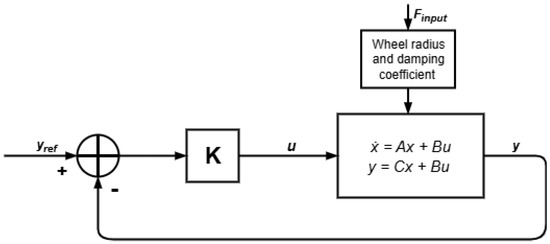
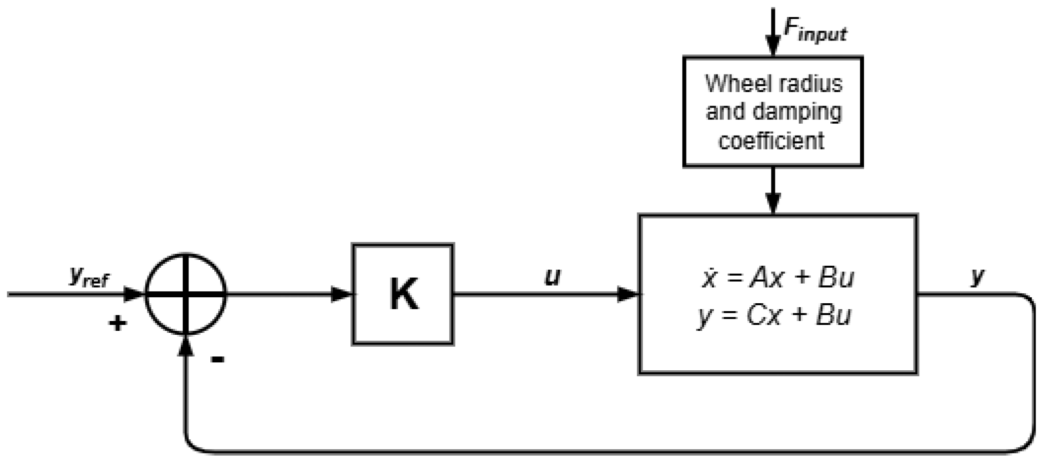
The current prototype, given the current motor and motor driver pairings, can only operate reliably under relatively small loads, and hence users with minor locomotion disabilities. A more powerful motor and motor driver pairing would allow for operation under high loads. In that case, the effective radius of the wheel would likely suffer significant deformations and a new controller that could account for this variation would likely to be required. A possible approach would be modelling the system as a unicycle with a wheel of variable radius, where the effective radius reflects the wheel’s deformation, altering matrices A and B in the model and consequently requiring adjusting the LQR gain matrix. Forces applied at each instant would have to be considered in the controller design, as shown in Figure 10.
Figure 10.
Block diagram of the full-state feedback LQR controller of the cane with user force input and varying wheel radius.
5. Results
The prototype was tested for its ability to overcome obstacles, reduce vibrations, for its intuitiveness, and ability of the flexible wheel to safely support the users during motion, in a range of scenarios that are representative of rehabilitation, domestic, and simple outdoors environments in which people with locomotion deficits have to move through. For the first two tests, a particularly compliant (soft) wheel was printed in order to simulate a flexible wheel under high load and act as a proof of concept for the capabilities of compliant tires.
5.1. Object Clearance Test Results
The maximum climbing height of each wheel and motor pairing was tested by attempting to climb obstacles of known heights, starting from 0.5 cm up to 7.5 cm with 1 cm intervals, with five attempts per pair.
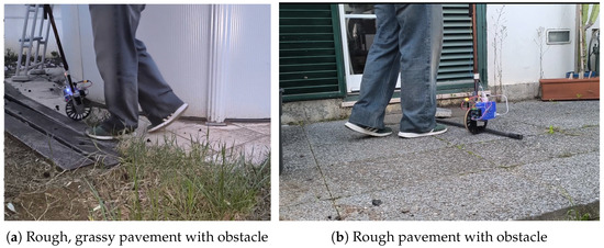
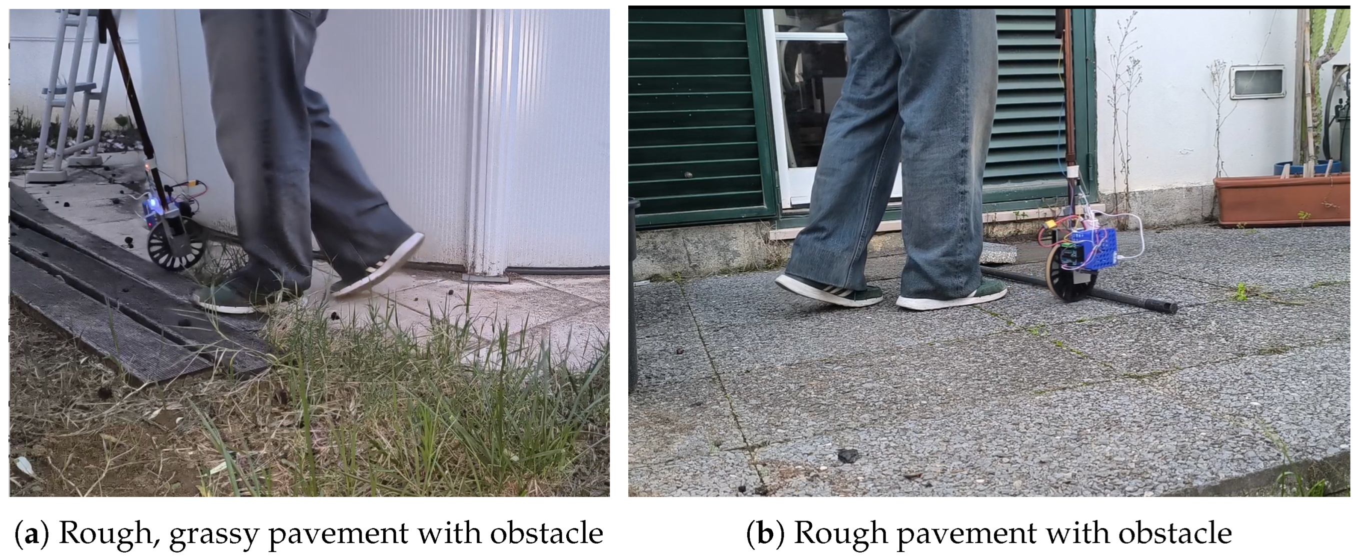
Figure 11 shows two snapshots of experiments in rough terrain, performed by an able-bodied user. All the experiments were performed by the same user.
Figure 11.
User without walking deficits testing the cane in rough terrain.
Table 1 shows a summary of the tests. A specially compliant wheel, named soft wheel, was included to emphasize the role of the deformable wheel, (without extreme compliance being necessarily a good property for the envisaged application).
Table 1.
Success percentage in overcoming obstacles (5 trials per wheel/height).
The soft wheel achieved the highest obstacle clearance for both motors. The rigid wheel, on the other hand, showed the lowest success rate, confirming that low compliance limits traction and the capability to overcome obstacles.
The hybrid wheel outperformed all the other intermediate compliant designs. The radial and the honeycomb wheels performed similarly, which is consistent with their similar deformation profile. Also, these designs performed marginally better than the rigid wheel, this is consistent with their nearly rigid behaviour under low loads. These results suggest that even a moderate structure flexibility can improve the ability to overcome obstacles, while excessive stiffness limits the traction when trying to do so. Regarding the motors, their difference in performance is in accordance with their torque characteristics. The faster motor, with its lower rated load and stall torques, performed significantly worse than the motor with lower rpm and hence it is not reported here. Taking this into account, even though slower motor has a considerably lower maximum speed, its overall climbing ability proved to be sufficiently better and consequently was selected for all subsequent tests. Quantitatively, the hybrid wheel successfully climbed obstacles up to 33% of its radius with a success rate of 100% and with partial success up to 46% of its radius. The soft wheel overcame obstacles equivalent to 60% of its radius with a success rate of 100%. These results further confirm that an increase in compliance leads to an increase in obstacle clearance capabilities, provided sufficient torque is available. Note that these tests were executed under loads compatible with the available motors and not loads with significance for the envisaged application. This, however, results from a tradeoff between the plasticity of the 3D printing material and the available motor torques. Moreover, it must be emphasized that these relatively small loads do not limit the scientific validity of the findings. In fact, a basic argument could be that if the wheel is modelled by a second order, linear, time invariant, system, as is often the case with elastic elements, and the elastic deformation limit is not reached, the results can be extrapolated to higher loads.
Furthermore, it is worth to emphasize that the first-order statistics used to report these clearance tests are a solid indicator of the capabilities of the cane. Each of the five runs per wheel occurred in slightly perturbed conditions as the test scenarios were staged in the real world (see the samples in Figure 11), i.e., the obstacles were not repositioned in the exact same location after one run and the rough pavement was not traversed in the exact same way. Therefore, higher-order statistics would be affected by these perturbations and any conclusions could be potentially misleading.
5.2. Shock Absorption Test Results
For the following tests, three wheel types will be used. The rigid wheel will be used as a control, the hybrid wheel will be used for its tradeoff between stiffness and flexibility, and the soft wheel will be used to demonstrate the ideal behaviour of a flexible wheel under sufficient torque. The tests demonstrated the ability of each wheel to overcome obstacles of equal height. These obstacles were higher than objects commonly found in households such as cables or rugs on the floor.
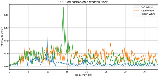
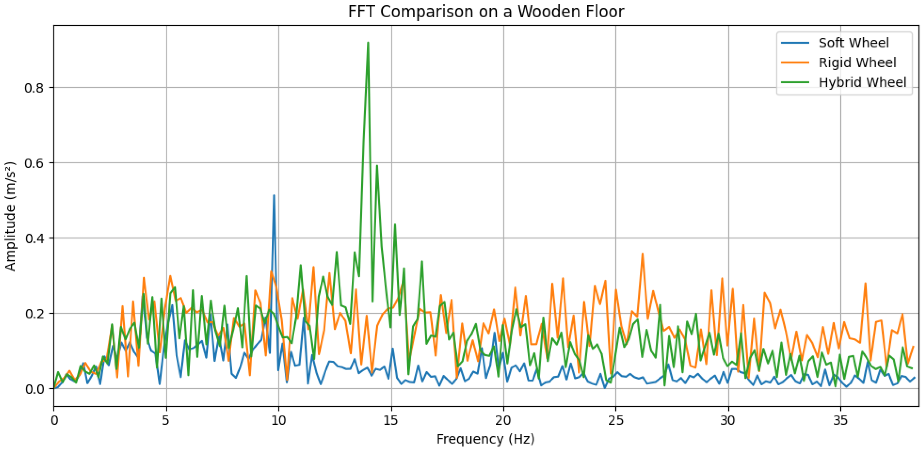
The wheels were tested among a variety of terrains to determine the response of the wheel under certain real scenarios. The cane was driven upright, and its acceleration along the y axis was recorded, from which we employed a Fast Fourier Transform to analyse the performance of each wheel. The same user, without locomotion deficits, performed these tests. The cane was maintained upright and the signal sent to the motor constant, ensuring that the differences observed is due to the wheel being used. The conditions of the ground surfaces were kept constant for the duration of each test of approximately 30 s.
In Figure 12, we can observe that the soft and hybrid wheels exhibit distinct acceleration peaks, caused by the spokes not deforming immediately upon contact with the surface. The soft wheel shows a peak at a lower frequency due to its smaller number of spokes compared to the hybrid wheel. At frequencies above 20 Hz, the rigid wheel has the highest amplitude of acceleration, followed by the hybrid wheel and the soft wheel. Below 5 Hz, all three wheels behave similarly.
Figure 12.
FFT comparison of the wheels on a wooden floor.
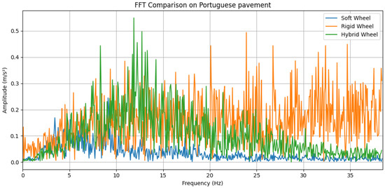
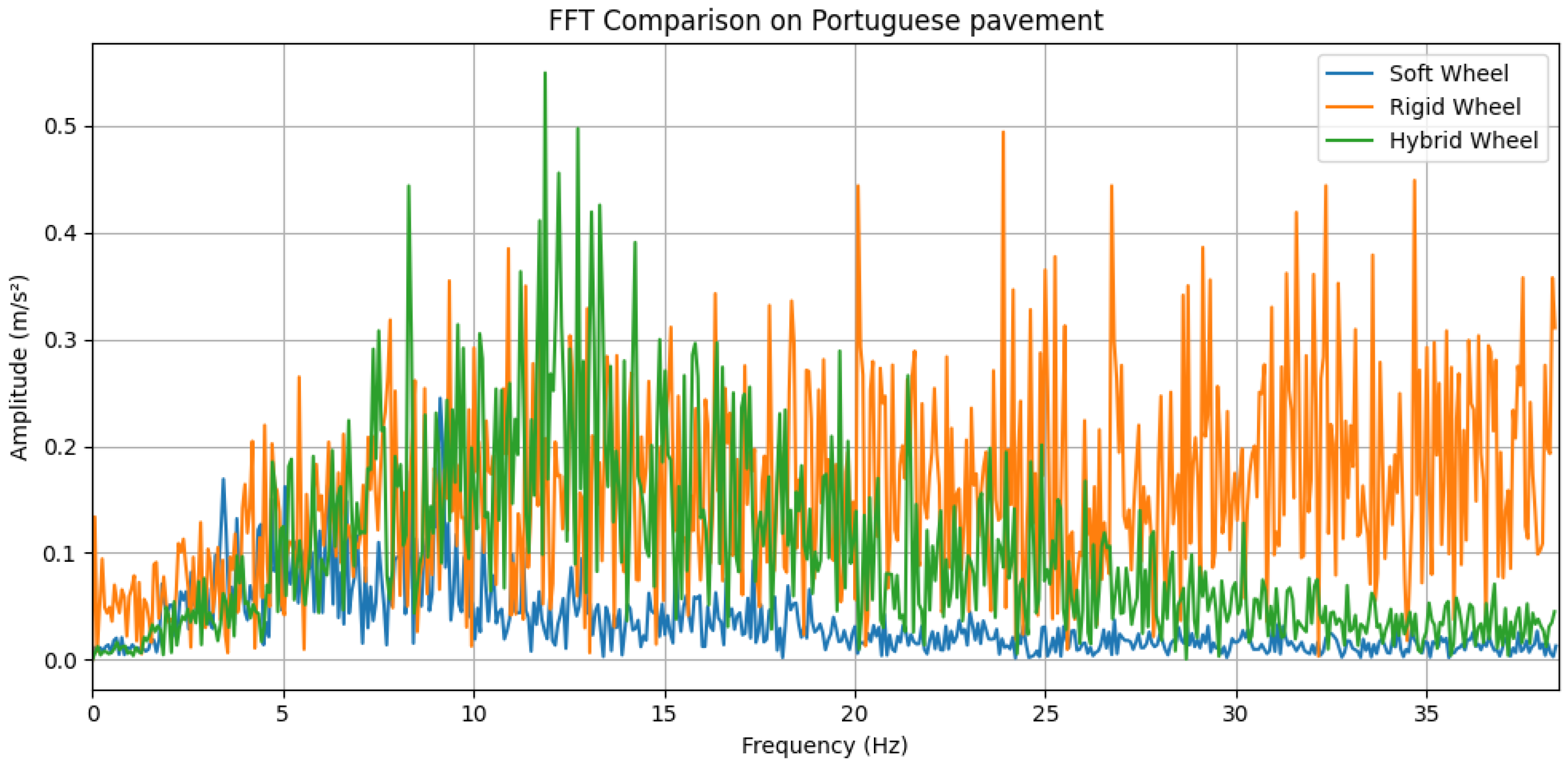
From Figure 13, we can observe that due to the irregularity of the surface, the rigid wheel, which was unable to dissipate most of the impact energy, presented the highest amplitude of acceleration in both low frequencies (below 5 Hz) and high frequencies (above 20 Hz).
Figure 13.
FFT comparison of the wheels on Portuguese pavement.
The moderate flexibility of the hybrid wheel caused a clear peak between 10 and 15 Hz. However, it performed better than the rigid wheel, particularly below 5 Hz and above 20 Hz. Although the soft wheel still displayed an acceleration peak around 10 Hz, its amplitude was considerably lower than on the flat wooden floor. The wheel deformation around the uneven surface reduced the influence of the individual spokes when compared to the flat surface. Overall, the soft wheel provided the most effective vibration damping, namely above 5 Hz.
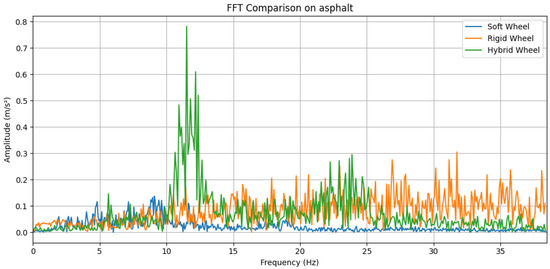
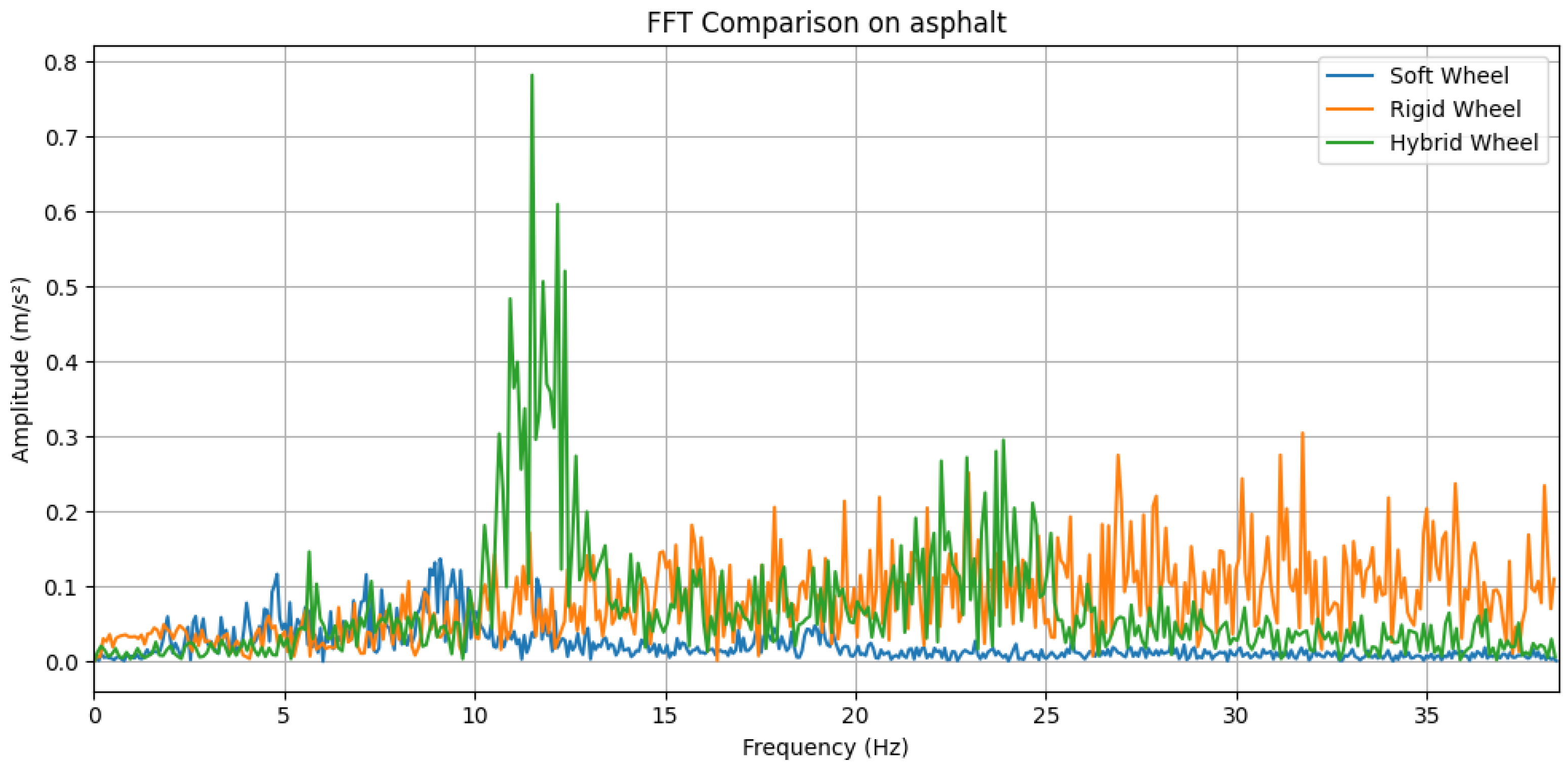
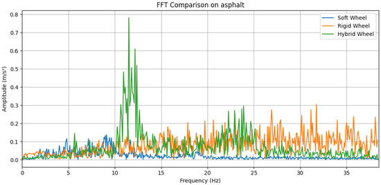
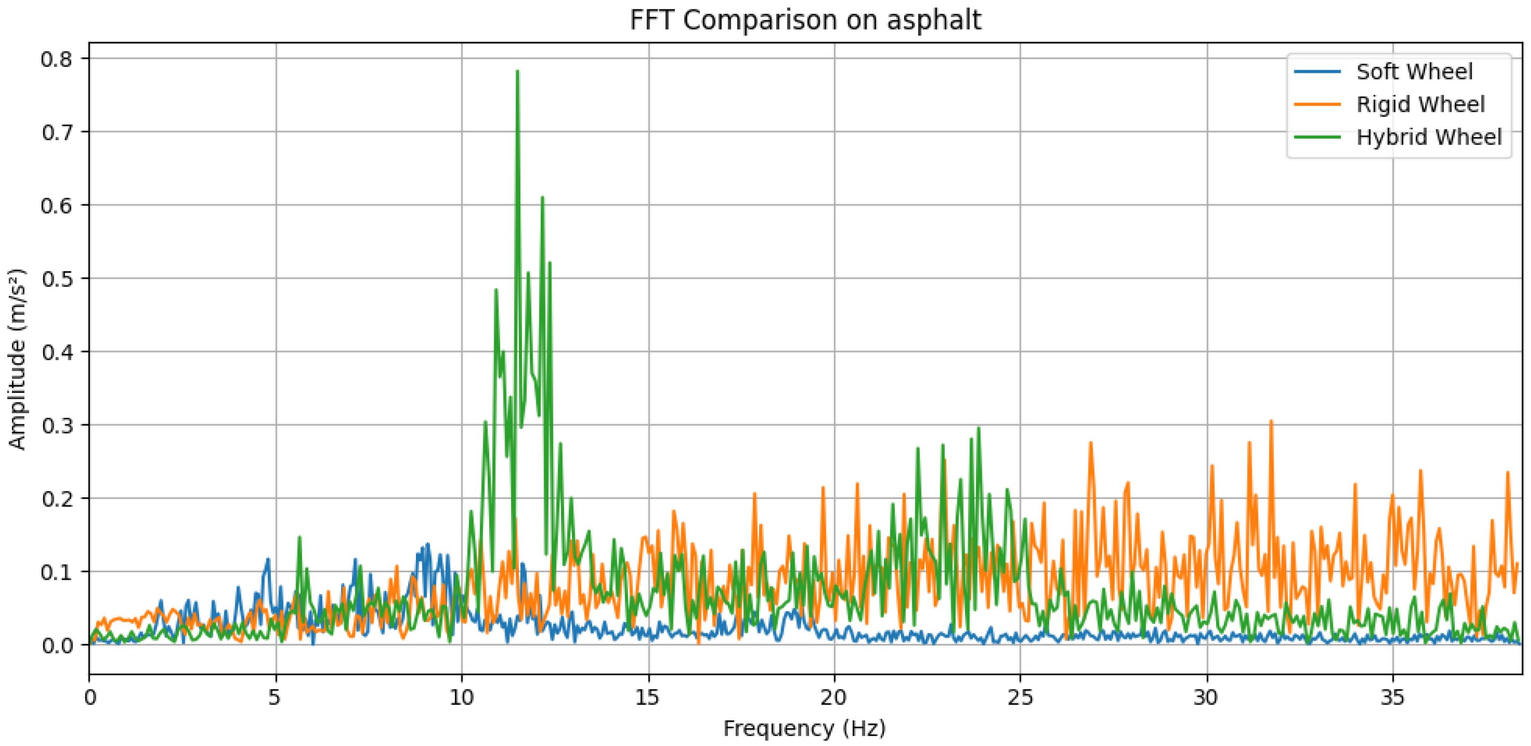
As seen in Figure 14, at low frequencies (below 10 Hz), all three wheels behave similarly, with the soft wheel showing a small peak near 10 Hz due to its spoke pattern. Between 10 and 15 Hz, the hybrid wheel shows a high amplitude peak, similar to the previous tests; however, unlike the previous examples, it exhibits a second, smaller peak, between 20 and 25 Hz. In this range, the hybrid wheel performs the worst out of the three. Above 25 Hz, the rigid wheel produces the highest acceleration amplitudes, followed by the hybrid wheel. Overall, above 10 Hz, the soft wheel performs better at mitigating vibrations than both the other two wheels.
Figure 14.
FFT comparison of the wheels on asphalt.
Figure 15 shows that the evenly spaced bars of the metal grate cause a distinct peak between 15 and 20 Hz for the rigid wheel. Its performance below 10 Hz and above 20 Hz is worse than both the hybrid and soft wheels.
Figure 15.
FFT comparison of the wheels on a metal grate.
Below 10 Hz, the hybrid wheel performs similarly to the soft wheel. However, near 15 Hz, it exhibits a characteristic peak due to its spoke structure.
The soft wheel does not show a distinguishable peak at around 10 Hz as observed on previous surfaces. In this case, the wheel conforms effectively to the gate, and the spokes do not significantly affect its vertical motion, showing a low degree of noise throughout its the range of frequencies. Consequently, it has the best performance of the three wheels over this type of surface.
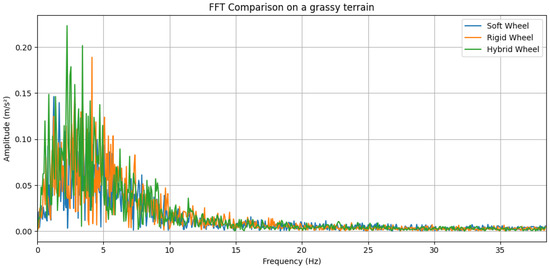
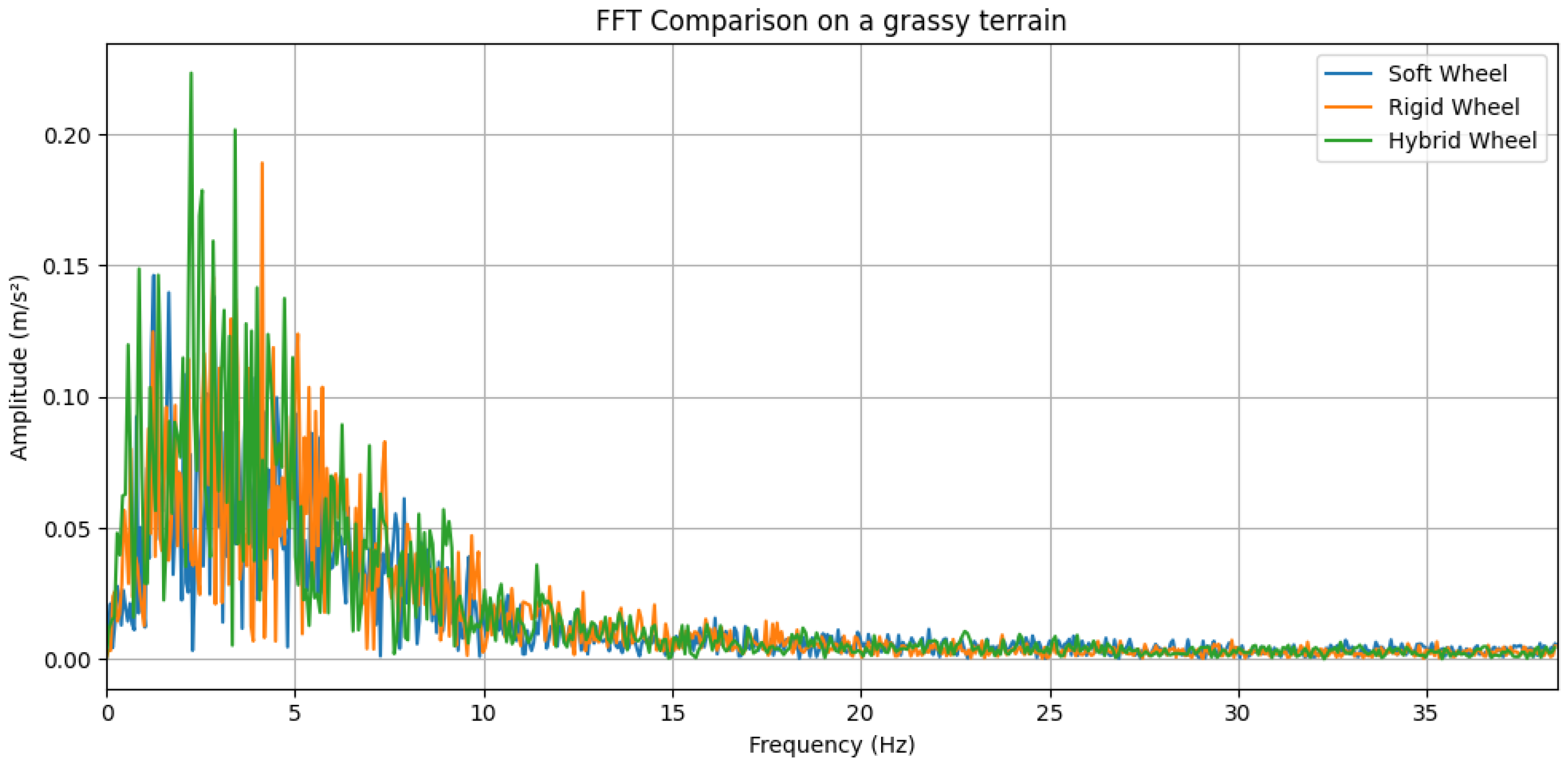
Finally, Figure 16 shows that all three wheels perform similar when traversing a grassy surface. All three wheels showed a peak in acceleration at low frequencies (0 to 10 Hz) and minimal amplitude of acceleration beyond 10 Hz.
Figure 16.
FFT comparison of the wheels on a grassy terrain.
Unlike the previously tested surfaces, where disturbances were directly transmitted to the wheels, and subsequently to the handle, the deformation of the grass allowed for some attenuation of the disturbances prior to travelling through the body of the cane. This resulted in a similar behaviour across all three wheels.
Although the cane experienced slight difficulties on this terrain, it was still able to traverse it, demonstrating the ability to traverse a surface that poses challenges for both traditional wheeled assistive devices and canes.
Overall, the deformable wheel was shown to be able of absorbing irregularities. Additional testing on different surfaces could further extend the characterization of the cane, namely in what concerns scenarios of maximal effectiveness.
5.3. Baseline Tests
Given the results of the previous tests, the hybrid wheel was selected as the most promising, as it is flexible while still maintaining enough structural integrity to support user safely. The participants were asked to operate the cane using the control algorithm basic developed in [25] on even surfaces, with minimal nonsmooth features (see Figure 17).
Figure 17.
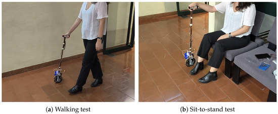
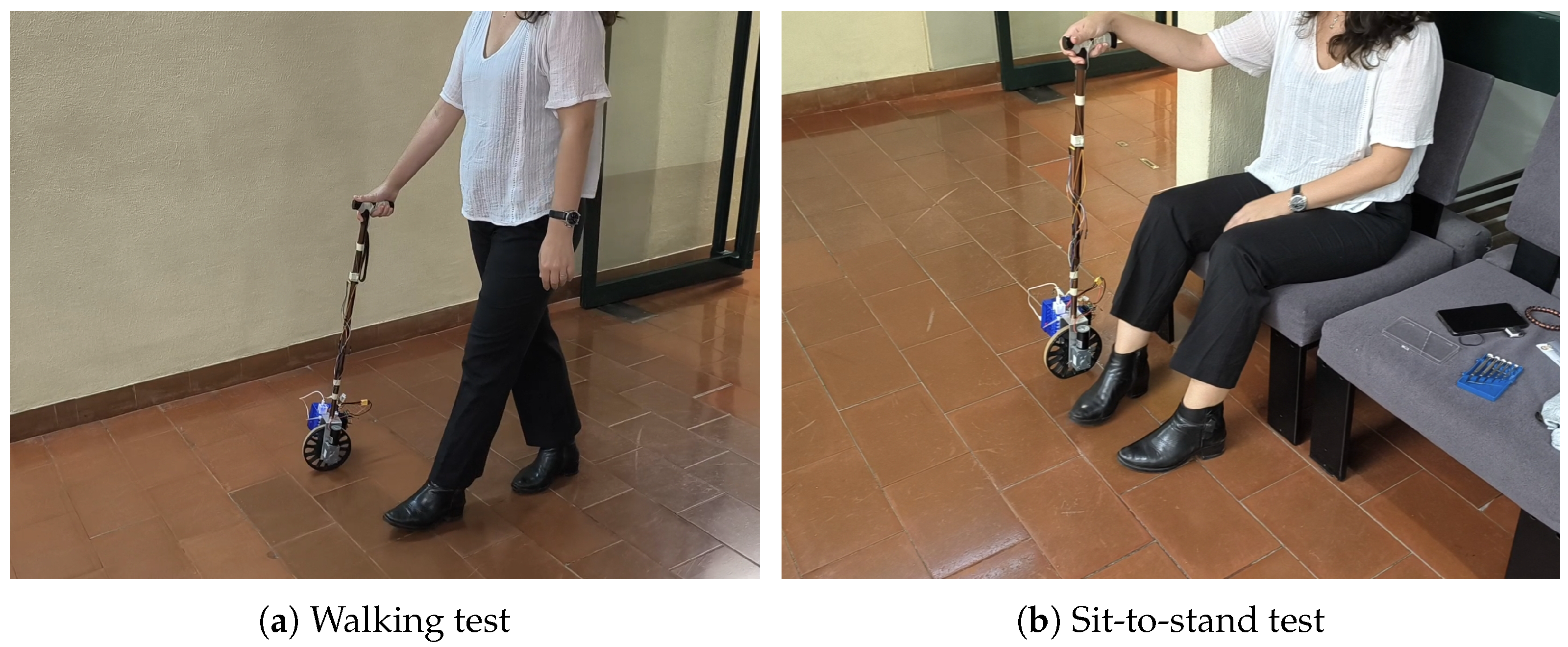
Baseline test with users without walking deficits.
The tests included (i) a short walk, (ii) a dual-task walking exercise along the same path, and (iii) a sit-to-stand followed by a stand-to-sit sequence. Two controllers were assessed: Controller A, identical to the basic controller developed in [25], and Controller B, with the parameters re-tuned for this work. The tuning consisted in perturbing the and parameters, around the optimal values and, empirically, verifying the acceptance by the users.
The first and third tests/exercises allow for the comparison of both of these controllers in basic real-world scenarios, while the dual-task exercise allows us to evaluate the intuitiveness of each controller when the user’s attention is divided, simulating typical conditions where environmental awareness is required.
The tests described in this section were conducted with five participants (). None of them presented any walking difficulties, although three of them have previously used a walking aid. Out of these three, one of them has previously used a unilateral walking aid (a single crutch). Prior to these, a therapist MD tested the cane to verify the usage and safety aspects. This experiment provides a usage baseline. The aim is to show that the cane has no feature capable of limiting locomotion.
The participants did not receive any information on the control strategy being used. They were only given a brief explanation on how the cane would behave, enough to understand how the cane moves.
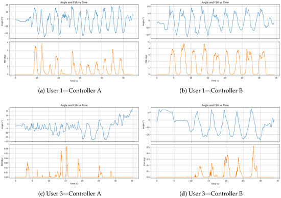
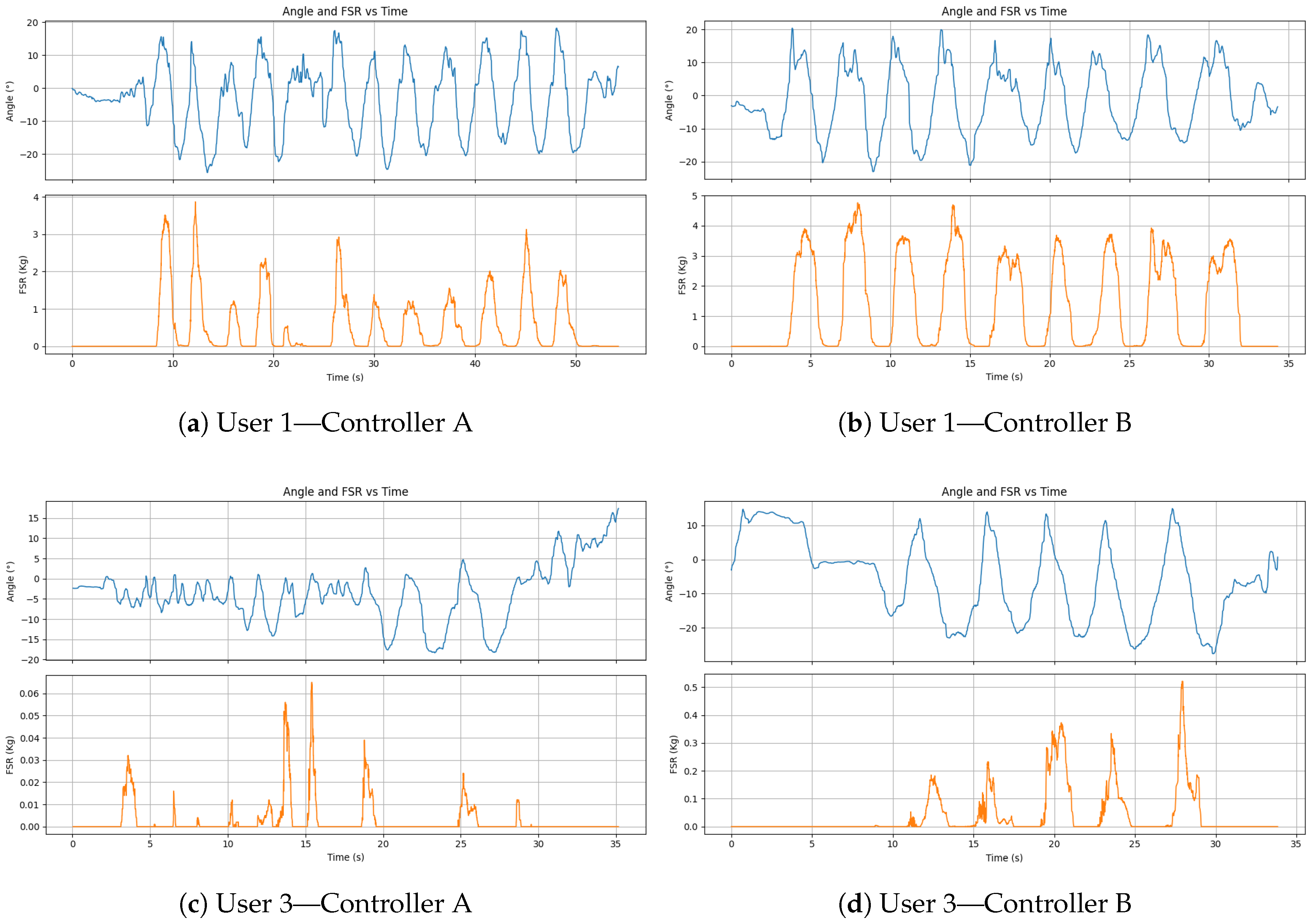
Each participant performed the tests using one of the control methods was asked a series of questions to assess their opinion on the movement. The same procedure was then repeated using the other control method, followed by the same set of questions, i.e., each participant underwent two runs with the cane. Figure 18 shows the angle of the cane and the force measured by the FSR at the handle.
Figure 18.
Cane angle (upper subplots) and force (lower subplots) at the handle for one of walking test of two of the users.
Table 2 shows the results on a simple Likert questionnaire on this experiment.
Table 2.
Basic Likert questionnaire for the baseline test.
After completing the tests with both controllers, the participants were asked an additional two questions, namely (i) how do the two control methods compare and (ii) what is the user perception on the influence of the deformable wheel on the behaviour of the prototype. Regarding the first question, all the five participants felt that Controller B felt “more stable” (opinion verbalized by the users). Regarding the second question, the majority felt that Controller B provided a greater sense of security, particularly on standing and sitting transitions. These verbalized opinions match what can be observed in Figure 18, namely in the force measured which is more regular for Controller B when compared to Controller A. The difference between the plots of the two users show clearly the variability between then and how the system can adjust its behaviour. However, some noted that Controller A felt more responsive, with one of the participants mentioning that the constant responsiveness made it difficult to establish a consistent gait rhythm, namely during the dual-task walking. Furthermore, some participants felt that they had to either focus on the cane, losing their concentration on the cognitive task, or focus on the task at the cost of coordination with the cane.
All of the participants found that during the dual-task walk, Controller B felt more intuitive, allowing them maintain a steadier support with the cane while performing the cognitive task simultaneously.
All of the users agreed that the flexible wheel did neither negatively impact the safety nor comfort of the cane. Three of the users, all of shorter stature, found that the reference angle on Controller B was too large. They reported that the cane leaned forward excessively, making it more difficult to handle the cane comfortably at times. This can be corrected by adjusting the length of the cane. In such cases, reducing the admissible leaning angle may also improve comfort. The other users found Controller B to be more accessible to new users, facilitating the leaning process when compared to Controller A. However, all of the users expressed either neutral or positive impressions in their first experience with both controllers, stating that with further practice both of these methods could be used effectively.
Additionally, both the hybrid wheel and the radial wheel with fewer spokes were tested in a series of short walking tests. The prototype successfully provided gait support, i.e., an additional stable support point the users can stick to while walking. The hybrid wheel had the highest acceptance of the two.
5.4. Tests with People with Mild Locomotion Deficits
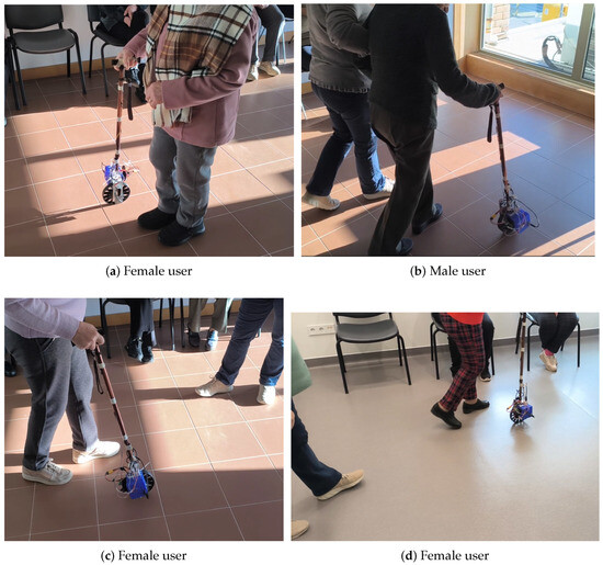
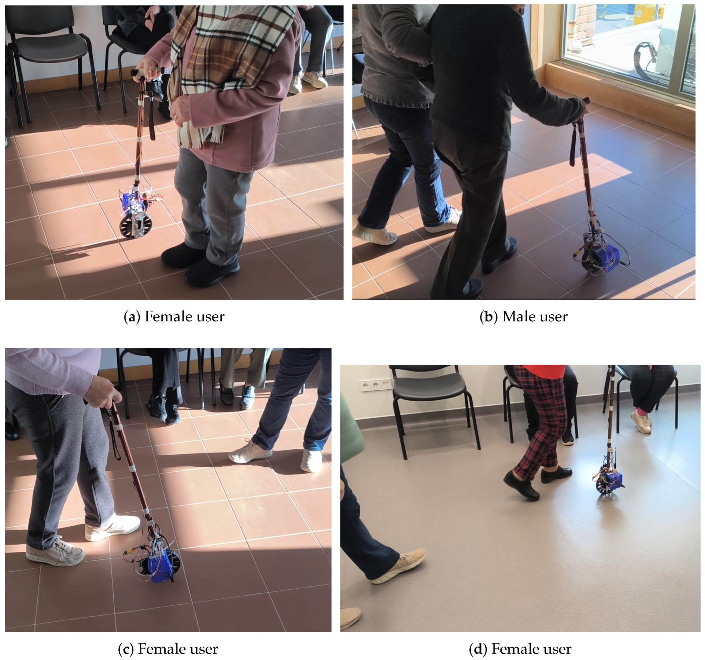
Testing with real users (), aged 65 to 80 years old, with locomotion limitations resulting from a variety of health conditions, under healthcare specialists supervision, has been carried out at a ULS (Local Healthcare Unit of the Portuguese Healthcare System). These users were not explicitly recruited for the experiment. Instead, they were participating in their regular rehabilitation sessions from where they were selected by the therapists given a priori knowledge on the healthcare condition. Moreover, the testing of the cane was not a substitute for their tailored therapy sessions and the participation was totally volunteer. The surfaces were completely flat or of very small roughness, essentially the tile joints on the floor. Figure 19 shows views of real users, during rehabilitation sessions, testing the cane under strict supervision of therapists.
Figure 19.
Real users, in a rehabilitation session, testing the cane under the supervision of therapists.
The data collected were simply (i) what was the general perception and (ii) would the user think something should be changed. While the first question scored as a 3-point Likert positive/neutral/negative or liked/do-not-know/not-liked opinion, the second question, asked after the first, was open and prone to the users elaborating as much as they wanted, without time constraints. The underlying principle is to minimize survey fatigue (see, for instance, [43]). The scores obtained in the first were 50%/25%/25%. The second question was answered mainly by the users that responded negatively in the first. The length of the cane and the discomfort induced by the to angle interval were the only negative aspects mentioned.
Even despite the slight deformation under low/normal loads, the increased support that results from a larger contact area with the ground (when compared to a standard, rigid, wheel) increases the user stability and comfort (if a user feels unstable there is a tendency to increase the pressure in the cane). It is worth to remark that this is a technical assessment from healthcare specialists; some real users might not be able to immediately identify some of the effects on their own body.
6. Conclusions and Future Work
As the world population ages and the demand for improved elder care grows, research into robotic assistive walking aids has expanded. Most of the work, however, tends to focus on smart walkers and other frame-type aids, while robotic canes, particularly compact, personal devices, remain relatively under explored. With this context, this work aimed to develop a compact robotic walking cane prototype based on previous research, capable of navigating through various surfaces while remaining lightweight, simple, and cost effective, allowing for a greater accessibility.
The deformable/compliant wheels demonstrated an ability to comply with a variety of surfaces, preserving stability and manoeuvrability. The tests showed that an increase in compliance, improving object clearance and shock absorption. However, the wheel design must balance flexibility and user support, which, given the variability of users, may be a difficult tradeoff. It must be able to deform under normal conditions while still allowing the users to put their weight on the cane without compromising the cane’s stability nor causing permanent deformation. This issue can be addressed in two different ways. Either further optimizing the wheel design so that it is more compliant while maintaining adequate support, or using a more powerful motor and motor driver pair capable of driving the wheel while allowing a significant deformation when necessary.
Adjusting/reconfiguring the cane for different classes of users may involve redesigning the wheel, and/or the control system, and possibly upgrading the motor. The use of adaptive control strategies is a relevant future direction. The use of the Gini index to adjust the parameters of the controller has been shown to yield relevant results [27], but the recent developments in machine learning are likely to extend the adaptability to the wide range of mild locomotion deficits.
Overall, this work, much like the previous ones, provides a foundation and baseline for future research on compact robotic canes with deformable wheels. The use of low-cost components and simple control methods make it simple to replicate and upgrade. Furthermore, though the preliminary assessment by the healthcare specialists and real users is positive and strengthens the assessment of the project, future work must include additional validation by both healthcare specialists and real users and extensive tests to confirm the shock absorption results. In addition, technologies from robots designed for rough terrains can be adapted to this area. Legged robots have been demonstrated to have an edge in such scenarios. For example, in [44], authors described a quadruped robot with a machine learning approach to select footholds and guide the robot to maintain the adequate stance. The role of such technologies, e.g., deep learning, in adjusting the behaviour of robotic devices to the limitations/disabilities of people is thus a natural area of study in the near future.
Author Contributions
Conceptualization, software, investigation, original manuscript preparation, T.F.; conceptualization, data curation, review and editing, supervision, project administration, funding acquisition, J.S.S.; resources, validation, review and editing, I.M.S.; validation, review and editing, A.M.O. All authors have read and agreed to the published version of the manuscript.
Funding
This work was supported by LARSyS FCT funding (DOI: 10.54499/LA/P/0083/2020 and DOI: 10.54499/UID/50009/2025).
Institutional Review Board Statement
The study was conducted in accordance with the Declaration of Helsinki. Ethical review and approval were waived for this study due to as it involved no harmful procedures and no personal data was recorded.
Informed Consent Statement
Informed consent was obtained from all subjects involved in the study.
Data Availability Statement
The data used are available on reasonable request to the corresponding author.
Conflicts of Interest
The authors declare no conflicts of interest. The funders had no role in the design of the study; in the collection, analyses, or interpretation of data; in the writing of the manuscript; or in the decision to publish the results.
Abbreviations
The following abbreviations are used in this manuscript:
| IMU | Inertial Measurement Unit |
| LQR | Linear Quadratic Regulator |
| FSR | Force Sensitive Resistor |
| NPT | Non-Pneumatic Tire |
| ADC | Analogue to Digital Converter |
| FFT | Fast Fourier Transform |
| TPU | Thermoplastic Polyurethane |
| GPIO | General Purpose Input Output |
| LiPo | Lithium Polymer |
References
- United Nations. Population Division: Median Age of Population; United Nations: New York, NY, USA, 2024. [Google Scholar]
- United Nations. Population Division: Graphs; United Nations: New York, NY, USA, 2024. [Google Scholar]
- Gell, N.; Wallace, R.; LaCroix, A.; Mroz, T.; Patel, K. Mobility device use in older adults and incidence of falls and worry about falling:Findings from the 2011–2012 national health and aging trends study. J. Am. Geriatr. Soc. 2015, 63, 853–859. [Google Scholar] [CrossRef] [Scilit]
- LaPlante, M.; Ge, H.; Aj, M. Assistive technology devices and home accessibility features: Prevalence, payment, need, and trends. Adv. Data 1992, 217, 1–11. [Google Scholar]
- Iezzoni, L.; McCarthy, E.; Davis, R.; Siebens, H. Mobility difficulties are not only a problem of old age. J. Gen. Intern. Med. 2001, 16, 235–243. [Google Scholar] [CrossRef] [Scilit]
- CDC. Web-Based Injury Statistics Query and Reporting System. Number of Injuries and Associated Costs. 2022. Available online: https://wisqars.cdc.gov (accessed on 1 January 2025).
- Monteiro, C. Perigos da Queda no Idoso. 2025. Available online: https://www.lusiadas.pt/blog/prevencao-estilo-vida/saude-familia/perigos-queda-idoso (accessed on 1 January 2025).
- Sainz Martín, M.; Merino, A.; González-Cobos, J.; Díaz, H.; Mingueza, Y. Riscos Domésticos Eentre os Idosos: Guia de Prevenção Destinado a Profissionais; Fundación MAPFRE: Lisboa, Portugal, 2010. (In Portuguese) [Google Scholar]
- Mali, N.; Restrepo, F.; Abrahams, A.; Sands, L.; Goldberg, D.; Gruss, R.; Zaman, N.; Shields, W.; Omaki, E.; Ehsani, J.; et al. Safety concerns in mobility-assistive products for older adults: Content analysis of online reviews. J. Med. Internet Res. 2023, 25, e42231. [Google Scholar] [CrossRef] [Scilit]
- Sivakanthan, S.; Candiotti, J.; Sundaram, A.; Duvall, J.; Sergeant, J.; Cooper, R.; Satpute, S.; Turner, R.; Cooper, R. Mini-Review: Robotic Wheelchair Taxonomy and Readiness. Neurosci. Lett. 2022, 772, 136482. [Google Scholar] [CrossRef] [Scilit] [PubMed]
- Martins, M.; Santos, C.; Frizera-Neto, A.; Ceres, R. Assistive mobility devices focusing on Smart Walkers: Classification and review. Robot. Auton. Syst. 2012, 60, 548–562. [Google Scholar] [CrossRef] [Scilit]
- Cha, J.; Hong, J.; Yoo, J.; Rha, D. Wearable Robots for Rehabilitation and Assistance of Gait: A Narrative Review. Ann. Rehabil. Med. 2025, 49, 187–195. [Google Scholar] [CrossRef] [Scilit]
- Tejima, N. Rehabilitation robotics: A review. Adv. Robot. 2000, 14, 551–564. [Google Scholar] [CrossRef] [Scilit]
- Van der Loos, H.; Reinkensmeyer, D. Rehabilitation and Health Care Robotics. In Springer Handbook of Robotics; Siciliano, B., Khatib, O., Eds.; Springer: Berlin/Heidelberg, Germany, 2008; Chapter 53; pp. 1223–1251. [Google Scholar]
- Speich, J.; Rosen, J. Medical Robotics. In Encyclopedia of Biomaterials and Biomedical Engineering; Marcel Dekker, Inc.: New York, NY, USA, 2004. [Google Scholar]
- Kawase, K.; Sato, T.; Kudo, S.; Nagano, A. Characteristics of upper limb joint mechanics with increased cane dependence during walking. J. Phys. Ther. Sci. 2024, 36, 614–619. [Google Scholar] [CrossRef] [Scilit]
- Cavaglià, M.; Sierra, S.; Palmerini, M.; Orlandi, S.; Múnera, M.; Cifuentes, C. Towards safer mobility: Developing and evaluating a fall detection system for a smart walker. In Proceedings of the 10th IEEE RAS/EMBS International Conference for Biomedical Robotics and Biomechatronics (BioRob), Heidelberg, Germany, 1–4 September 2024; pp. 1623–1628. [Google Scholar]
- Meligy, R.; Ahmad, A.; Mekid, S. An IOT-based smart wheelchair with EEG control and vital sign monitoring. Eng. Proc. 2024, 82, 46. [Google Scholar] [CrossRef] [Scilit]
- Tokunaga, D.; Nishikawa, S.; Kiguchi, K. Cane robot with spherical wheels adaptable to the multi-legged robot. In Proceedings of the 7th Jc-IFToMM International Symposium (In Conjunction with the 30th Jc-IFToMM Symposium on Theory of Machines and Mechanisms), Kitakyushu, Japan, 22–23 June 2024; Volume 7, pp. 130–134. [Google Scholar]
- Perez, C.; Fung, J. An Instrumented Cane Devised for Gait Rehabilitation and Research. J. Phys. Ther. Educ. 2011, 25, 36–41. [Google Scholar] [CrossRef] [Scilit]
- Matalenas, L.; Hu, T.; Veeramachaneni, V.; Muth, J. A Cane for More than Walking: The Design of a Smart Cane for Physical Therapy. In Proceedings of the Human Factors and Ergonomics Society Annual Meeting, Washington, DC, USA, 19–23 September 2016; Volume 60, pp. 1063–1067. [Google Scholar] [CrossRef] [Scilit]
- Taniguchi, K.; Takanishi, A. Design and Evaluation of the Walking Cane Handle Grip. Int. J. Autom. Smart Technol. 2015, 5, 203–207. [Google Scholar] [CrossRef] [Scilit]
- Afzal, M.; Hussain, I.; Jan, Y.; Yoon, J. Design of a Haptic Cane for Walking Stability and Rehabilitation. In Proceedings of the 13th International Conference on Control, Automation and Systems (ICCAS 2013), Gwangju, Republic of Korea, 20–23 October 2013. [Google Scholar]
- Sun, Y.; Xiao, C.; Chen, L.; Chen, L.; Lu, H.; Wang, Y.; Zheng, Y.; Zhang, Z.; Xiong, R. A review of intelligent walking support robots: Aiding sit-to-stand transition and walking. IEEE Trans. Neural Syst. Rehabil. Eng. 2024, 32, 1355–1369. [Google Scholar] [CrossRef] [Scilit]
- Neves, G. Auxiliar de Locomoção Compacto para Pessoas com Mobilidade Reduzida. Master’s Thesis, Instituto Superior Técnico, Lisbon, Portugal, December 2020. [Google Scholar]
- Bollinger, P.; Neves, G.; Sequeira, J. Control of a Robot Cane for Locomotion Assistance. In Proceedings of the 15th APCA International Conference on Automatic Control and Soft Computing (CONTROLO 2022), Caparica, Portugal, 6–8 July 2022; Lecture Notes in Electrical Engineering; Springer: Berlin/Heidelberg, Germany, 2022; Volume 930. [Google Scholar]
- Neves, G.; Sequeira, J.; Santos, C. Lightweight and compact smart walking cane. PeerJ Comput. Sci. 2023, 9, e1563. [Google Scholar] [CrossRef] [Scilit]
- Mpofu, E.; Chronister, J.; Johnson, E.; Denham, G. Aspects of Culture Influencing Rehabilitation and Persons with Disabilities. In The Oxford Handbook of Rehabilitation Psychology; Kennedy, P., Ed.; Oxford Handbooks Online; Oxford University Press: Oxford, UK, 2012. [Google Scholar]
- Lee, Y.; Yang, C.; Kim, S.; Jung, J.; Kim, J. Development of a caterpillar-type walker for the elderly people. Appl. Sci. 2022, 12, 383. [Google Scholar] [CrossRef] [Scilit]
- Bouton, A.; Grand, C.; Amar, F. Motion control of a compliant wheel-leg robot for rough terrains crossing. In Proceedings of the IEEE International Conference on Robotics and Automation (ICRA2016), Stockholm, Sweden, 16–21 May 2016; pp. 2846–2851. [Google Scholar] [CrossRef] [Scilit]
- Um, D.; Park, J.; Shin, J.; Lee, W. A Social Robot, “Dali”, for Aging in Place Technology. J. Robot. 2018, 2018, 6739652. [Google Scholar] [CrossRef] [Scilit]
- Oh, S.; Kim, H.; Jeon, S.; Shin, B.; Ryu, B.; Kim, Y. Design of a mobile robot with 2-DOF compliant wheel-legs by using a linear spring. Microsyst. Technol. 2023, 29, 1189–1196. [Google Scholar] [CrossRef] [Scilit]
- Lee, D.; Jung, G.; Sin, M.; Ahn, S.; Cho, K. Deformable Wheel Robot Based on Origami Structure. In Proceedings of the IEEE International Conference on Robotics and Automation (ICRA 2013), Karlsruhe, Germany, 6–10 May 2013. [Google Scholar]
- Godden, T.; Mulvey, B.; Redgrave, E.; Nanayakkara, T. Patswheel: A passively-transformable single-part wheel for mobile robot navigation on unstructured terrain. IEEE Robot. Autom. Lett. 2024, 9, 5512–5519. [Google Scholar] [CrossRef] [Scilit]
- Liu, B.; Xu, X. Mechanical behavior and mechanism investigation on the optimized and novel bio-inspired nonpneumatic composite tires. Rev. Adv. Mater. Sci. 2022, 61, 250–264. [Google Scholar] [CrossRef] [Scilit]
- Itadera, S.; Aoyama, T.; Hasegawa, Y.; Aimoto, K.; Kato, K.; Kondo, I. A clinical pilot study on posture stabilization via light contact with cane-type companion robot. ROBOMECH J. 2019, 6, 17. [Google Scholar] [CrossRef] [Scilit]
- Prasad, S.; Bhalsing, K.; Jhunjhunwala, K.; Lenka, A.; Binu, V.; Pal, P. Phenotypic variability of essential tremor based on the age at onset. Can. J. Neurol. Sci./J. Can. Sci. Neurol. 2019, 46, 192–198. [Google Scholar] [CrossRef] [Scilit] [PubMed]
- Agarwal, S.; Biagioni, M. Essential Tremor; StatPearls Publishing LLC: Treasure Island, FL, USA, 2025. [Google Scholar]
- Gironell, A.; Pascual-Sedano, B.; Aracil, I.; Marín-Lahoz, J.; Pagonabarraga, J.; Kulisevsky, J. Tremor Types in Parkinson Disease: A Descriptive Study Using a New Classification. Park. Dis. 2018, 2018, 4327597. [Google Scholar] [CrossRef] [Scilit] [PubMed]
- Hart, J.; Hall, M.; Wrigley, T.; Marshall, C.; Bennell, K. Body weight support through a walking cane in inexperienced users with knee osteoarthritis. Gait Posture 2018, 67, 50–56. [Google Scholar] [CrossRef] [Scilit]
- Weiss, C.; Seplaki, C.; Wolff, J.; Kasper, J.; Agree, E. Self-selected walking speed was consistent when recorded while using a cane. J. Clin. Epidemiol. 2008, 61, 622–627. [Google Scholar] [CrossRef] [Scilit] [PubMed]
- Xu, X.; McGorry, R.; Chou, L.; Lin, J.; Chang, C. Accuracy of the microsoft Kinect™ for measuring gait parameters during treadmill walking. Gait Posture 2015, 42, 145–151. [Google Scholar] [CrossRef] [Scilit]
- Ghafourifard, M. Survey Fatigue in Questionnaire Based Research: The Issues and Solutions. J. Caring Sci. 2024, 13, 214–215. [Google Scholar] [CrossRef] [Scilit]
- Chen, L.; Ye, S.; Sun, C.; Zhang, A.; Deng, G.; Liao, T.; Sun, J. CNNs based Foothold Selection for Energy-Efficient Quadruped Locomotion over Rough Terrains. In Proceedings of the IEEE International Conference on Robotics and Biomimetics, Dali, China, 6–8 December 2019. [Google Scholar]

Disclaimer/Publisher’s Note: The statements, opinions and data contained in all publications are solely those of the individual author(s) and contributor(s) and not of MDPI and/or the editor(s). MDPI and/or the editor(s) disclaim responsibility for any injury to people or property resulting from any ideas, methods, instructions or products referred to in the content. |
© 2026 by the authors. Licensee MDPI, Basel, Switzerland. This article is an open access article distributed under the terms and conditions of the Creative Commons Attribution (CC BY) license.