


Abstract
The flexible upper-limb exoskeleton robot (exosuit) is composed of fabrics, soft actuators and compliant force-transmitting structures, which provides assistance or rehabilitation training for the shoulders, elbows, wrists and hands. By realizing human–robot collaboration, this kind of system has the advantages of comfort, light weight and portability, thus promoting motor function recovery and neural plasticity. This review establishes a classification and comparison framework for flexible upper-limb exoskeletons based on the actuation modalities and systematically summarizes the research progress under different actuation modalities. The relevant literature published from 2015 to 2025 was retrieved from the EI, IEEE Xplore, PubMed and Web of Science databases. After screening according to the preset inclusion and exclusion criteria, a total of 64 original research papers meeting the criteria were finally included for analysis. According to the actuation modalities, the flexible upper-limb exoskeleton robot is classified, and all kinds of systems are summarized and compared. Motor–cable/tendon actuation and pneumatic/hydraulic actuation have advanced substantially and are approaching technical maturity for flexible upper-limb exoskeletons. Meanwhile, designs based on passive/hybrid mechanisms (e.g., elastic energy storage elements and clutches) and new intelligent material actuations are showing a diversified development trend. In the future, the development is expected to further focus on lightweight and compliance, and by integrating multimodal sensing and feedback control, motion intention recognition and human–robot interaction theories, actuation systems will be developed towards modularization, intelligence and high-power density, in order to achieve more comfortable, lighter and more effective flexible upper-limb exoskeleton systems.
1. Introduction
1.1. Background
In recent years, functional impairments caused by stroke, spinal cord injury, neuromuscular disorders, and population aging have severely affected patients’ activities of daily living (ADLs), particularly upper-limb functions required for everyday tasks [1,2]. Therefore, the upper-limb exoskeleton robotics, as an interdisciplinary field integrating artificial intelligence, robotics, biomedical engineering, and human–robot interaction, has demonstrated substantial potential in medical rehabilitation [3,4,5].
Traditional rigid upper-limb exoskeletons usually employ motor-driven linkage mechanisms, which can provide large output force/torque and high control accuracy; however, their structures are often cumbersome, and it is difficult to align precisely with the human anatomical joint axes, uncomfortable to wear, and comes with higher safety risks, which collectively limit their long-term and widespread use in home and community settings [6,7,8,9,10].
As an emerging rehabilitation and assistive technology, the flexible upper-limb exoskeleton robot (exosuit) has significant advantages over the rigid exoskeleton in terms of wearing comfort, human–robot interaction safety, and motion compliance [11]. However, the adaptability introduced by the flexible design also brings new challenges at the system level. Adapting to the deformation of the interface and the soft tissues of the human body, the device’s output is unable to be stably transmitted to the joints through fixed geometric relationships. The changes in the tightness of the straps and the slippage during the wearing process will cause the effective lever arm and the force transmission path to drift over time and with different postures. This leads to the same drive command generating different joint torques or terminal forces in different individuals and under different wearing conditions. Furthermore, the flexible force transmission is often accompanied by significant nonlinear factors (such as friction, backlash, hysteresis, compressibility, thermal lag, etc.), which further reduces the model accuracy and control transparency. Therefore, the key factors determining the upper limit of system performance and the degree of transformability are no longer solely the control strategy itself, but rather the collaborative design of the actuation modality and the force transmission architecture. In other words, the selection of the adaptive drive and the driving mode constitutes the core challenge in the development of flexible upper-limb exoskeletons [12,13,14,15].
Based on this, the actuation method should be regarded as the core enabling technology for achieving efficient and safe human–robot assistance in the implementation of flexible exoskeletons. It not only determines the power source, but also determines how force is generated, how it is transmitted to the limbs, how it is regulated under wearable constraints, and ultimately how it affects the response speed, wear comfort, portability and repeatability of the system. Therefore, in flexible upper limb exoskeletons, the more fundamental issue is no longer “which actuator is used”, but how the actuation method can jointly achieve force generation, force transmission, human–robot interface coupling and control at the system level.
The novelty of this review lies in its actuation-modality-centered perspective for analyzing flexible upper-limb exoskeleton robots. While existing review articles often focus on specific device categories, isolated actuator types, rehabilitation outcomes, or control strategies, they rarely treat the actuation modality as the primary system-level variable linking mechanical output, force-transmission architecture, human–robot interface, and translational feasibility. In flexible exoskeletons, however, the actuation modality does not merely define the power source; it fundamentally shapes how assistance is generated, transmitted, and perceived under real wearing conditions.
Based on this, the uniqueness of this article mainly lies in three aspects. Firstly, this article establishes a unified classification framework for actuation methods, incorporating motor–cable/tendon actuation, hydraulic actuation, elastic element actuation, and intelligent material actuation into the same comparison system. Secondly, this article emphasizes the actuation methods, thereby going beyond the traditional review method of listing devices one by one, and forming a more systematic overall explanatory framework. Thirdly, this article summarizes and horizontally compares the common engineering bottlenecks faced by different actuation methods, including transmission nonlinearity, interface slip, preload drift, hysteresis effect, energy supply, thermal management, and safety constraints. It further discusses the impact of these issues on future lightweight, compliant, modular, and intelligent flexible exoskeleton design. Therefore, the uniqueness of this article not only lies in summarizing the research progress in recent years, but also in proposing a system-level analysis framework for actuation methods to support the understanding, comparison, and future design of flexible upper-limb exoskeletons.
1.2. Literature Research
This review retrieved literature related to flexible upper-limb exoskeleton robotic actuation modalities published between 2015 and 2025 from the EI, IEEE Xplore, PubMed, and Web of Science databases. In each database, Boolean operators, wildcards, synonyms, and alternative spellings were applied to capture the broadest possible range of relevant studies (Table 1). This systematic review and meta-analysis were conducted in accordance with the Preferred Reporting Items for Systematic Reviews and Meta-Analyses (PRISMA) guidelines. The PRISMA checklist is provided in Supplementary Materials, Table S1.
Table 1.
Databases used and respective search entries.
A total of 528 publications were initially identified through database searching. The retrieved literature was charted to show the number of documents for each year as shown in Figure 1a. The quantities of various types of literature were presented in Table 2 and depicted in a pie chart as shown in Figure 1b. As illustrated in Figure 2, these records were subsequently subjected to a rigorous screening procedure based on predefined inclusion and exclusion criteria. The inclusion criteria required that: (1) the publication be an original research article; (2) the study focuses on flexible upper-limb exoskeleton robots/exosuits/wearable robots primarily intended for assistance, training, or rehabilitation of the shoulder, elbow, wrist, and/or hand; (3) the devices employ predominantly textiles, soft straps, soft-bodied structures, compliant mechanisms, or soft actuators in the human–machine interface and/or force transmission architecture; and (4) the paper explicitly describes at least one actuation approach and its force transmission mechanism, and be classifiable into one of the categories defined in this review: motor–tendon/cable actuation (including Bowden cables/tendons), pneumatic actuation, hydraulic actuation, passive or semi-passive actuation (elastic energy storage with clutches or brakes), or smart-material-based actuation (e.g., SMA, EAP/DEA). In addition, two further studies were incorporated through reference tracing to ensure comprehensive coverage of the field. After removing duplicate records and excluding studies that did not meet the screening criteria, a total of 64 studies were included in this review, representing the current research landscape on actuation systems for flexible upper-limb exoskeleton robots.
Figure 1.
(a) The number of publications in individual types. (b) The number of publications in individual years.
Table 2.
Comparison of major actuation methods for flexible upper-limb exoskeletons.
Figure 2.
PRISMA flow diagram of the literature screening and selection process.
2. Motor–Cable/Tendon Actuation Type
Motor–cable/tendon actuation achieves the assistive output by converting the rotational output of the motor into tension in flexible cables, tendons, or Bowden wires. In a typical configuration, the motor is usually located far from the trunk or back, and its rotation drives the line shaft or pulley to wind or unwind the cables. The resulting tension is transmitted to the anchor points on both sides of the target joint through fabric channels, low-friction sheaths, or Bowden tubes. When the cables shorten, the tension acts along the preset force transmission path and forms an effective force arm relative to the anatomical joint center, thereby generating an auxiliary moment at the joint. Some systems use antagonistic cable pairs to simulate the synergistic action of the agonist and antagonist muscles, achieving bidirectional flexion and extension or multi-degrees-of-freedom coordinated movements. The actual effectiveness of this actuation mode is highly dependent on the wiring geometry, anchor point layout, preload retention, and friction characteristics. Therefore, although motor–cable/tendon actuation has high controllability and low remote inertia, its actual output is often affected by friction, backlash, hysteresis, and wear slip, resulting in significant operational dependence of tension transmission and torque output.
2.1. Elbow–Hand Actuation
From 2016 to 2017, the Xiloyannis team from Nanyang Technological University in Singapore proposed a flexible upper limb exoskeleton suit based on fabric to assist elbow flexion and extension and hand grasping [16,17,18,19,20]. The actuation unit of this system is composed of two Bowden cables wound around an axis in a prime mover and antagonist muscle manner. The Bowden cables are contracted and released through the forward and reverse rotation of the motor, and a transmission mechanism is designed to solve the pre-tightening problem of the line drive. This exoskeleton suit has the advantages of light weight, portability, and low power consumption. The weight of the elbow-wearing part is less than 200 g. From 2018 to 2020, in order to improve the auxiliary effect of the line-driven exoskeleton suit, the Xiloyannis team designed an arm gravity compensation controller and tested the electromyographic signals of eight healthy subjects [21,22,23]. The average reduction in human elbow torque was 59.20 ± 5.58%, and the muscle activation decreased by 64.8 ± 7.66%. These results indicate that the exosuit can reduce both the mechanical demand at the joint level and the local muscle activation required to perform the assisted movement. However, the reduction in EMG activity should be interpreted with caution: EMG is a useful indicator of local muscle unloading, but it is also sensitive to electrode placement, signal normalization, inter-subject variability, and changes in muscle recruitment strategy. Therefore, EMG reduction alone should not be regarded as a complete measure of assistive effectiveness. In this context, the reported elbow torque reduction (59.20 ± 5.58%) provides a more direct mechanical indicator, while EMG reduction (64.8 ± 7.66%) reflects a physiological correlate of reduced muscular effort. A more comprehensive evaluation would ideally compare these results with additional outcome measures, such as metabolic cost, task completion performance, or movement quality, which were not explicitly reported in these studies. Currently, the cable-actuation flexible upper-limb exoskeleton suit studied by the Xiloyannis team is only applied to the elbow joint and hand of the human body. Comparisons of two types of Xiloyannis exosuit are shown in Table 3.
Table 3.
Comparison of Xiloyannis exosuits.
This type of actuation of exoskeleton suits can simulate human muscles through line drive to achieve multi-degrees-of-freedom movements of the upper limbs. However, due to the action point of the line drive being on the human body surface, the transmission angle is small and the transmission performance is poor, making it difficult to drive the shoulder joint to perform large-range movements. From an evaluation perspective, this also suggests that future studies on cable-actuation exosuits should report not only EMG reduction, but also joint-level torque, task-level performance, and, where possible, metabolic or energetic outcomes, so that local muscle unloading can be distinguished from broader functional improvement.
2.2. Shoulder and Elbow Actuation
In 2017, the Lessard team from the University of California proposed a linear-driven flexible upper-limb exoskeleton named CRUX [24,25], which can provide assistances to both the shoulders and elbows. This research, on the one hand, builds a musculoskeletal tension model based on OpenSim to simulate the changes in the lengths and torques of muscle groups such as biceps brachii and brachioradialis during elbow joint movement, and accordingly adjusts the control strategy; on the other hand, it uses motion capture to identify the minimum extension lines of the upper limbs, thereby deriving the Bowen lines distribution and completing the wiring design. CRUX uses six micro-motors to drive the cables, with each motor corresponding to a pair of prime mover/antagonist muscles, and the drive unit is placed on the back. The overall weight of the device is approximately 1.3 kg. It can provide shoulder and elbow support without significantly restricting the wearer’s mobility and flexibility. It can also be used for upper-limb functional training and assistance in daily activities in various environments. Additionally, the team combined CRUX with virtual reality mirror visual feedback training to conduct immersive game-based physical therapy experience verification. This type of research shows that the key of the linear drive system is not only in the drive parameters, but also in the synergy of “muscle-skeletal model—wiring geometry—control strategy” [26].
Currently, this motor and Bowen line driving method is the most common design method for flexible upper-limb exoskeletons. In response to the common problem of local pressure and interaction force generated by force transmission on the human body surface when using linear drive, Wei et al. [27] proposed a flexible upper-limb exoskeleton suit driven by Bowden cables in 2018. They optimized the wearing comfort based on the arm-line drive simulation model to minimize the human–robot interaction force (Figure 3a). Furthermore, Li et al. [28,29] developed a 7-degrees-of-freedom flexible upper-limb exoskeleton suit based on the musculoskeletal tension line model (Figure 3b). They also proposed a control method that simulates the principle of human muscle control, making the similarity between the exoskeleton’s movement trajectory and that of the human body exceed 87%. They also tested the assistance effect through electromyographic signals, and the results showed that the muscle activation degree decreased by 58.17% after the exoskeleton helped. In a more simplified system implementation, Pont-Esteban et al. [30] proposed a linear-driven flexible upper-limb exoskeleton, with two DC motors pulling the Bowen lines to drive the flexion and extension movements of the shoulder and elbow (Figure 3c). Samper-Escuder et al. [31,32] proposed a backpack-style linear-driven flexible upper-limb exoskeleton suit that can assist in shoulder (only 90°) and elbow movements. The total weight of 890 g in the backpack (Figure 3d). This exoskeleton suit contains multiple layers of textiles, and the tension is transmitted through the embedded Bowen lines in the fabric, and the activation degree of the muscles can be obtained through muscle electrical testing, which reduces by 26.36% with the assistance of this exoskeleton.
Figure 3.
Shoulder and elbow actuations [24,25,26,27,28,29,30,31,32,33,34]. (a) CRUX (b) 7-DOF exosuit (c) Pont-Esteban exosuit (d) Samper-Escuder exosuit (e) TSA (f) Shoulder-sensing exosuit.
A more quantitative comparison of these systems indicates that the actual shoulder assistance challenges not only have qualitative differences but also are reflected in the reported performance range. Firstly, in terms of the weight of the wearable burden, the reported system weights range from approximately 890 g for the backpack module in the Samper-Escudé design to about 1.3 kg for the full CRUX system, suggesting that even the “lightweight” systems with cable-actuation shoulder assistance capabilities still require a considerable remote driving mass. Secondly, in terms of the motion coverage range, the Samper-Escudé system only reports shoulder support up to 90°, indicating that the assistance effect is mainly limited to a limited functional range rather than the entire shoulder working area. Thirdly, although Li et al. reported a trajectory similarity of over 87% and a 58.17% reduction in muscle activation, as well as Samper-Escudé et al. reporting a 26.36% reduction in muscle activation, these indicators mainly reflect the overall assistive effect rather than the direct shoulder torque transmission. In other words, even though it has been proven that there are physiological benefits, in most current studies, the actual size and stability of the shoulder assist torque have not been fully quantified. This itself reflects a key limitation in this field: it is widely recognized that factors such as force arm drift, friction loss, and posture-dependent path variations have an impact, but these situations are rarely reported through direct shoulder torque or transmission efficiency indicators under similar conditions.
It is worth noting that most shoulder assistance is still limited by the unstable effective arm force caused by cable friction, routing bending, and wear slip, resulting in insignificant shoulder assistance or significant changes with posture. This limitation can be quantitatively understood as a reduction in the effective joint output relative to the nominal cable tension: as the curvature of the path increases and the clothing moves on the body, the same actuator input may result in completely different effective torques, because both the cable transmission efficiency and the force arm will change simultaneously. Therefore, the current challenge faced by the linear drive of the shoulder joint not only lies in generating sufficient cable force, but also in maintaining this force as a stable and usable shoulder torque during posture changes. This suggests that the shoulder linear drive system still needs further optimization in wiring routing, anchor point layout, and tension control robustness.
In addition to the traditional “motor + Bowden cable” scheme, Hosseini et al. [33] proposed a flexible upper-limb exoskeleton driven by surface electromyography signals (Figure 3e). It uses twisted pair actuators (TSAs) as the drive source (maximum tension 140 N, bandwidth 2–3 Hz), and connects the forearm through tendons to achieve single-arm/double-arm elbow joint assistance. The function was verified using electromyography signals of the biceps and triceps muscles. This scheme has advantages in the compactness of the drive module, but the local compression and comfort issues caused by the contact of cables with the forearm are still prominent. From a comparative perspective, the TSA system indicates that the compact tendon drive system can still provide a considerable pulling force output (140 Newtons), but its currently reported applications are limited to elbow assistance rather than shoulder support. This further suggests that the main obstacle in shoulder usage is not merely the compactness of the driver but rather maintaining the stable transmission of torque in larger and more complex joint movements. On the other hand, Varghese et al. [34] proposed a flexible exoskeleton suit with shoulder movement sensing capabilities (Figure 3f). It uses bionic tendons (Bowden cables) to simulate the functions of shoulder muscles and measures the tendon stretching state through sensors to visualize the muscle movement state; further, a neural network is utilized to establish a mapping model from the sensors to the joint space, with the root mean square errors of azimuth and elevation angles being 5.43° and 3.65°, respectively. These error levels provide additional quantitative indicators for the challenges of the shoulder cable drive system: even in perception and state estimation tasks, the kinematics of the shoulder are highly sensitive to the path state and tendon behavior, which means that the uncertainties in both the drive and perception are interrelated. Therefore, future research on shoulder drive should not only report overall functional results, but also report direct measurement indicators, such as the effective shoulder assist torque, torque fluctuations under posture changes, transmission efficiency under different path curvatures, and interface sliding conditions during repetitive movements.
The comparison table of different forms of shoulder and elbow actuation is shown in Table 4. This “state visualization” idea provides a new path for rehabilitation training evaluation and drive design, but its generalization ability and long-term stability in complex postures still need to be further verified.
Table 4.
Comparison table of different forms of shoulder and elbow actuation.
2.3. Hand Actuation
The linear drive flexible exoskeleton hand is one of the most common types of flexible exoskeleton hands. This type of exoskeleton hand typically embeds cables into a soft glove and uses specific wiring to transfer the motor output force to the fingertips. This enables the movement of multiple finger joints to be driven by a single motor. The greatest advantage of the linear drive flexible exoskeleton hand is that the motor is placed away from the hand, which greatly reduces the weight and volume of the exoskeleton hand and improves the wearing comfort, which is conducive to the application of the exoskeleton hand in life assistance. However, the transmission efficiency of the linear drive flexible exoskeleton hand is low and the human–robot interaction is poor, which limits its application.
Kang et al. [35,36] from Seoul National University in South Korea developed an exoskeleton hand Exo-Glove Poly II with linear actuation (Figure 4). The glove part of this exoskeleton is made of silicone material instead of the traditional flexible fabric, which makes the glove structure more compact and easier to clean, with greater transparency and visualization effect. The weight of this glove is 104 g, and the weight of the drive system is 1.14 kg. The drive part is placed on the table or wheelchair, which can greatly reduce the load on the hand. Popov et al. [37] from Korea’s Korea University developed a portable flexible exoskeleton hand Graspy Glove, which can be applied to daily life activity assistance. In terms of structural design, the flexion and extension movements of the thumb and three fingers (except the little finger) all adopt bidirectional actuators. This exoskeleton hand is one of the devices with the highest power-to-weight ratio in existing portable daily life assistance devices, and with a traditional 3000 mAh battery supply, it can continuously and effectively operate for 4 h and complete the corresponding daily life activity tasks. However, this exoskeleton hand will concentrate the stress of linear drive at the fingertips, reducing the wearing comfort of the exoskeleton.
Figure 4.
Hand actuations [35,36].
Overall, the “remote motor installation—cable transmission—flexible clothing” architecture has become one of the most representative configurations in the flexible upper-limb exoskeleton system. Its main value lies not only in reducing the weight at the end, but also in being able to achieve low inertia, high controllability, and strong potential for structural integration through wearable auxiliary functions. By placing the motor away from the joint and transmitting force through cables or Bowden tubes, this system can reduce the inertia and volume around the limb while maintaining the flexibility of wearability. However, the actual performance of this architecture is fundamentally limited by the consistency of force transmission rather than solely determined by the output of the actuators. In cable-actuation exoskeletons, the auxiliary torque provided at the joint is greatly affected by nonlinear transmission effects (such as friction, clearance, lag, and the interaction between the cable and the tube), as well as the uncertainty of human coupling caused by sliding, soft tissue deformation, and posture-related force arm changes. Existing research has shown that precise force control based on Bowden transmission remains a core challenge, and the transmission efficiency itself can vary significantly depending on the structural conditions; for example, a report case on Bowden transmission shows that under specific wiring conditions, its efficiency is approximately 72.59%, highlighting the strong dependence of effective output results on the geometric shape of the cable and the design of the interface.
From the perspective of the implementation of the actuation method, the key technical issues of the motor–cable/tendon system can be summarized into six closely related aspects. First, the path design and anchor point layout must simultaneously meet biomechanical compatibility and force arm stability, as the attachment position directly determines the generation of effective torque and the distribution of interface pressure. Second, the robustness of control remains a major issue because the transmission chain introduces nonlinear and time-varying friction hysteresis phenomena; therefore, recent research increasingly emphasizes friction compensation, model-based transmission control, and repetitive or learning-based compensation strategies to improve tension tracking and interference suppression capabilities. Third, the transmission efficiency must be improved by reducing static and dynamic friction losses, as well as optimizing path curvature, cable–pipe support, and cable–pipe matching. Fourth, preload management is crucial because the drift or relaxation of preload directly reduces response speed, passive transparency, and output repeatability. Fifth, bidirectional drive and antagonistic layout are essential for achieving more natural joint assistance, reducing the limitations of unidirectional traction, and supporting multi-degrees-of-freedom coordination. Sixth, system-level quality and configuration optimization remain very important: although remote driving reduces the inertia of the limb, the quality, volume, and ergonomic characteristics of the drive device installed on the back or trunk still have a significant impact on the overall portability and usability of the system.
In summary, current research trends indicate that the next stage of development of motor–cable/tendon exoskeleton equipment will no longer mainly rely on further improving the nominal drive power, but rather on enhancing transmission accuracy, passive transparency, and consistency of wearability. In particular, advancements in Bowden cable-tube force transmission design, low-cost tension estimation, sensor-free or reduced sensor control, and adaptive online calibration are likely to be key factors in improving the repeatability of assistive effects in practical wearable scenarios.
3. Pneumatic/Hydraulic Actuation Type
The curved pneumatic/hydraulic actuator generates joint assistance by converting the internal fluid pressure into controllable bending deformation. Its working principle relies on an anisotropic structural design: when pressurized fluid enters the soft cavity, the cavity itself has an expansion tendency, but this expansion is selectively constrained by the fiber-reinforced layer, strain-limiting layer, geometric asymmetry structure, or local stiffening area. Therefore, the actuator does not undergo uniform expansion but bends towards the side with weaker constraints. This curvature change induced by pressure can form equivalent joint torque when the actuator spans or adheres to the limb segments. For soft composite actuators, their bending output is mainly determined by the elastic body stiffness, fiber winding angle, cavity shape, and reinforcement layer layout; for pneumatic flexible joints, their structure emphasizes “joint-like” output, simulating the rotational response similar to a hinge through local cavity geometry and constraint design. Since these actuators output in a bending form, they can better fit the human joint movement trajectory and distribute contact pressure more uniformly than rigid structures. However, their driving behavior is usually accompanied by significant nonlinearity, mainly resulting from material hyper elasticity, fluid compressibility, hysteresis effect, and pressure-deformation coupling, which makes modeling, repeatability, and precise torque control more difficult.
3.1. Curved-Type Actuation
The curved-type and linear-type actuation constitute the two core output forms of the pneumatic/hydraulic-driven flexible upper-limb exoskeleton. The curved-type actuation directly generates the required equivalent torque for joint rotation through the controllable bending deformation after being compressed, which can weaken the reliance on strict alignment of the anatomical axis to a certain extent and distribute the human–machine contact pressure with better compliance. Therefore, it is most widely applied in elbow, shoulder, and finger flexion and extension assistance. Correspondingly, the linear-type actuation mainly outputs axial push/pull forces. Usually, it converts linear tension into joint rotation or multidirectional drive through a muscle-like antagonistic/cooperative arrangement. The most typical representative is pneumatic artificial muscle (PAM). Based on the above classification, this paper introduces the soft composite structure (fiber-reinforced soft actuator) in the curved-type actuation and its design mechanism, and then further discusses the linear-type actuation scheme represented by PAM and its adaptation method in upper-limb assistance.
3.1.1. Soft Composite Structure
The soft composite structure is composed of two or more layers of different flexible materials, and each layer of the materials has different properties, orientations and shapes. The air/hydraulic soft composite structure is obtained through biomimetic research based on the physiological structure of creeping animals. Its structure is composed of stretchable elastomer materials and non-stretchable fiber-reinforced materials, which can form special air/hydraulic cavities. By changing the structure of the elastomer and fiber layers, the anisotropic stiffness of each direction can be altered. And then, anisotropic bending motion is achieved under the action of pneumatic/hydraulic drive. Due to its ability to perform flexible movements that can adapt to human joint movements, this type of structure is widely used in flexible exoskeletons.
Koh et al. [38] from the National University of Singapore proposed a flexible elbow exoskeleton based on pneumatic soft composite structure (Figure 5a). The actuator of this exoskeleton is composed of an elastomer body formed by 3D printing molds, a nylon strain-limiting layer and a nylon radial reinforcement layer. After inflation, it can achieve bending and is embedded in fabric to form a flexible upper limb exoskeleton for the elbow. The verification on six healthy subjects showed that this system could drive the elbow joint to reach approximately 50% of the normal joint range of motion. This work proved the lightweight and biomimetic bending feasibility of the soft composite structure for elbow wear, but its motion range is still limited by the geometric and pressure level of the actuator.
Figure 5.
Soft composite structure [38,39,40]. (a) a flexible elbow exoskeleton (b) an aerodynamic soft composite actuator (c) a 2-degrees-of-freedom shoulder flexible exoskeleton.
Ma et al. [39] from BeiHang University designed an aerodynamic soft composite actuator, which restricts radial expansion and enhances axial elongation by setting non-expandable constraint materials on the circumferential surface (Figure 5b). This resulted in the formation of the driving output. The team embedded this actuator into the fabric and developed a flexible upper-limb exoskeleton that covers the shoulders, elbows, wrists and hands. The weight of the worn part is approximately 1075 g. The experimental results showed that this exoskeleton could lift the arm to 67°. However, this elevation angle is still insufficient to meet the typical requirements of daily upper-limb activities. The output capacity and torque level still need to be further enhanced.
To meet the multi-degrees-of-freedom requirements of the shoulder, Natividad et al. [40] from the National University of Singapore proposed a 2-degrees-of-freedom shoulder flexible exoskeleton, which uses modular flexible actuators to simulate the movement of the humerus (Figure 5c). This flexible actuator is composed of multiple material composites and can achieve large-range bending motion (>360°) under low pressure (10 kPa). After combining the flexible actuator with fabric, a shoulder flexible exoskeleton suit was made. At the neutral position, this flexible exoskeleton suit can provide 11.15 N·m of torque, and at a shoulder elevation of 90°, it can provide 4.44 N·m of torque. A force test of the flexible exoskeleton suit on a healthy subject was conducted, and the maximum muscle activation degree during shoulder flexion was reduced by 65%, and the maximum muscle activation degree during shoulder abduction was reduced by 34%. Although this study demonstrated the potential of low-pressure large deformation and certain torque output, its overall structural stiffness is low, and it lacks sufficient support for the upper limb’s own weight, reflecting the typical trade-off between “adaptation—bearing” in the soft composite actuator.
The key advantage of the soft composite structure route lies in the ability to achieve diverse bending modes through material selection and fiber constraint design, and its ease of integration with textiles, and its enhanced human–robot compatibility. The main bottlenecks lie in insufficient output torque and bearing support capacity, the working pressure level and safety constraints, as well as poor predictability of deformation under complex postures (difficult modeling and control).
3.1.2. Pneumatic Flexible Joint
Pneumatic flexible joints are typically constructed with flexible materials as “joint units”, and their anisotropic stiffness is changed by adjusting the cavity geometry and local constraints, which can control bending during inflation/discharge. Compared with the soft composite structure, they place greater emphasis on the joint-based output form and modular integration.
Pneumatic flexible joints are actuators designed using flexible materials, achieving bending motion by altering the anisotropic stiffness of the actuators. Ang et al. [41] at the National University of Singapore designed a tubular pneumatic flexible joint and modeled the flexible joint to predict the output force under different air pressures (Figure 6a). The tubular pneumatic joint is a 3D-printed flexible actuator, with constraints set to achieve the maximum output force, and the output force of different flexibility materials was tested. The flexible actuator made of preferred materials was embedded in the elbow sleeve, forming an elbow flexible exoskeleton. The worn part of this elbow exoskeleton weighs 230 g. At a pressure of 200 kPa, the actuator composed of 20 tubular flexible elements can generate a maximum output torque of 28 N·m, which is sufficient to meet the torque requirements for elbow joint flexion. Oguntosin et al. [42] from the UK also designed a flexible joint that can drive the human elbow joint to flex and extend under positive and negative pressures (Figure 6b). However, the flexible joints often have material nonlinearity and pressure-driven hysteresis, which limits model accuracy, increases control difficulty, and affects their repeatability and interpretability in “quantitative assistance” scenarios.
Figure 6.
Pneumatic flexible joint exoskeleton [41,42,43]. (a) a 3D-printed flexible actuator (b) a flexible joint (c) an airbag-type flexible exoskeleton.
In terms of shoulder training and protection, Harvard University’s O’Neill et al. [43] developed an airbag-type flexible exoskeleton for shoulder joint training, combining two pneumatic flexible actuators to achieve external rotation, internal rotation, and horizontal flexion and extension movements of the shoulder joint (Figure 6c). The main airbag is composed of five independent small air cavities, and the main airbag and a four-bar linkage cooperate with inflation/discharge to complete the external rotation and internal rotation movements of the shoulder joint, and a trapezoidal air cavity is designed under the armpit to complete the horizontal flexion and extension movements of the shoulder joint. This airbag-type exoskeleton is not only lightweight and comfortable but also provides protection for the shoulder joint, improving the safety of the exoskeleton, demonstrating the advantages of “airbag structure—safety protection—training task” collaborative design.
3.1.3. Pneumatic/Hydraulic Flexible Exoskeleton Hand
In the flexible exoskeleton hand, pneumatic actuators are usually placed on the dorsal side of the fingers and are fixed to the fabric base using nylon fasteners or stitching. Specific cavity geometries generate specific deformations under pressure to drive finger flexion/extension or gesture movements, which can realize rehabilitation training and life assistance functions.
Harvard University’s Polygerinos et al. [44] proposed an aerodynamic exoskeleton glove based on soft silicone materials, integrating elastic materials with internal channels through pneumatic networks and achieving finger bending by adjusting the pressure of the air chambers (Figure 7a). This work utilized geometric analysis and finite element models to study the bending curvature and force response of the driver, and experimental and simulation results showed that the glove could assist in rehabilitation training and provide a large grasping auxiliary force, but its driving components were large in volume and weight, making it inconvenient to carry.
Figure 7.
Pneumatic/hydraulic flexible exoskeleton hand [44,45]. (a) an aerodynamic exoskeleton glove (b) Exo-Glove.
To address the issues of stress concentration at the assembly connection points and individual fit adjustment, Seoul National University in South Korea’s Yun et al. [45] proposed the customizable aerodynamic flexible assist glove Exo-Glove PM (Figure 7b), using a rigid-flexible coupling actuator: flexible airbags are placed at the finger joints to adapt to the movement characteristics, and rigid connections are used between the finger joints to fix the relative positions and support the adjustment of the driver spacing according to the length of the phalanges, which can enhance the adaptability to different hand shapes. However, this solution requires additional power sources and components, which affects the portability of the system to some extent.
In terms of hydraulic routes, Harvard University’s Polygerinos et al. [46] developed a hydraulic-driven flexible exoskeleton hand, which is a flexible exoskeleton hand that integrates rehabilitation training and life assistance. The flexible driver of this exoskeleton hand is made of fiber-reinforced materials, with a semi-circular cross-section and strong extensibility. Under hydraulic drive, it can achieve four types of movements. Its glove part weighs 285 g, and the driver is installed on the dorsal side, not affecting the user’s grasping actions. However, due to the large number of hydraulic drive components (hydraulic pumps, solenoid valves, etc.), it will reduce the portability of the exoskeleton system, which is an unavoidable constraint in the engineer application of hydraulic flexible gloves.
3.2. Linear Actuation (Pneumatic Artificial Muscle)
In pneumatic/hydraulic flexible exoskeletons, linear drives typically take the form of pneumatic artificial muscles (PAMs), especially the McBain type driver. This driver was originally designed by Joseph L. McBain in the 1950s for orthopedic applications. A typical McBain driver consists of an internally inflatable air bladder and an external woven mesh sleeve. When inflated, the internal air bladder expands radially, and the woven sleeve converts this radial expansion into axial contraction, thereby generating tension [47]. Due to its high force-to-weight ratio, inherent flexibility, and muscle-like contraction characteristics, the McBain type PAM has become the most prominent representative of linear fluid drive forms in flexible upper-limb exoskeletons, especially in antagonistic or synergistic joint drive configurations.
Andrikopoulos et al. [48] proposed a flexible wrist exoskeleton based on the PAM drive, which has similar functions to human muscles (Figure 8a). The wrist joint has four PAMs, two on the top and two on the bottom. When the top two are inflated and the bottom two are deflated, the wrist joint is in an extended state, and vice versa; when the inner two are inflated and the outer two are deflated, the wrist joint extends, and vice versa for internal and external movements. This PAM-driven flexible exoskeleton can not only achieve wrist rehabilitation training but also assist in daily life activities. Al-Fahaam et al. [47] in the UK developed a flexible wrist exoskeleton, with the driving part consisting of three contracting and two elongating PAMs, which cooperatively complete wrist joint flexion, extension, and internal and external rotation movements (Figure 8b). This exoskeleton has the advantages of portability and compact structure, and can be applied in life assistance, but the contracting and elongating artificial pneumatic muscles in this system have nonlinear coupling problems during movement. Yao Jiantao et al. from Yanshan University developed a wrist joint flexible exoskeleton, which uses four PAMs to cooperate to achieve wrist joint flexion/extension and internal/external rotation movements. A film pressure sensor is embedded in the glove to sense the grip force of the palm and can monitor the assistance effect and safety protection of the wrist joint in real time. It should be noted that when PAM directly acts on the wearing end, it often faces problems such as large device volume and unfavorable layout for wearing comfort; at the same time, the air source and valve control system further limit portable deployment, especially more obvious in life assistance scenarios.
Figure 8.
Linear actuation exoskeleton [47,48]. (a) a flexible wrist exoskeleton (b) a flexible wrist exoskeleton of UK.
Overall, the pneumatic/hydraulic-driven flexible upper-limb exoskeletons have been well studied in terms of the elbow and hand. The basic paradigm is to use a fluid medium through a pump source to transfer pressure to specific chambers or flexible joints, generating force/displacement output through the geometry and anisotropy of the chambers. The bending-type actuators (soft composite structures, flexible joints) have significant advantages in biomimicry and compliance, making them suitable for joint rotation drive and finger flexion; the linear PAM has appeal in terms of force-to-weight ratio and muscle-like drive, suitable for antagonistic arrangement to achieve multidirectional joint movements as shown in Table 5. However, these systems generally have two system-level bottlenecks: one is the integration of power sources and valve control/pump sources leading to a decrease in force-to-weight ratio and portability (air source/hydraulic source, valve group, piping, sealing maintenance); the other is the nonlinearity of material and fluid drive (hysteresis, compressibility, friction, coupled deformation), which limits modeling accuracy and increases control difficulty, thus facing engineering and convertibility bottlenecks in daily life activity assistance scenarios.
Table 5.
Comparison of pneumatic/hydraulic soft actuator types.
4. Elastic Element Actuation
The flexible upper-limb exoskeleton based on elastic elements generates auxiliary output by controlling the deformation of flexible structural components (such as spring sheets, flexible hinges, elastic beams, compliant links, or other deformable energy storage elements). Unlike the motor–cable/tendon system and pneumatic/hydraulic soft actuators, which directly convert electrical or hydraulic energy into stretch or pressure-driven motion, elastic element drive relies on the storage and release of mechanical strain energy. In a typical configuration, external displacement input (provided by small motors, linear actuators, links, or user-induced limb movements) causes the elastic elements to bend, stretch, twist, or compress. As the elements deform, strain energy accumulates within the structure; when the system is released or reaches a specified motion stage, the elastic elements generate restoring force or restoring torque, which is transmitted to the limb through the flexible interface.
From a biomechanical perspective, this drive mode is particularly attractive because the deformation of the elastic structure can partially adapt to the movement of the instantaneous joint rotation center (ICR). Therefore, compared to rigid drive chains, the elastic element system can reduce alignment errors, improve interface compliance, and enhance wearing comfort. In practical applications, elastic elements can assume different functional roles: they may provide direct auxiliary torque, gravity compensation, peak load buffering, phase-dependent assistance, or compliance force transmission adaptation. However, due to the availability of the output, which largely depends on the effective stiffness of the elastic elements, the allowed strain, the structural geometry, and the energy storage capacity, pure elastic element drive is usually limited in continuous high-torque applications, especially in proximal joints such as the shoulder and elbow.
For the drive method based on elastic elements, the required parameters can be summarized into four groups. Firstly, input parameters include displacement input, preload, and in a hybrid system, input power or stroke provided by external motors or linear actuators. Secondly, structural and material parameters include elastic modulus, stiffness curve, element thickness, length, cross-sectional geometry, allowable strain, bending radius, and fatigue resistance. These parameters directly determine the energy storage capacity and the achievable restoring force/torque. Thirdly, control and boundary condition parameters include phase matching conditions, clutch/brake timing (if applicable), preload adjustment, and the release strategy for storing elastic energy. Finally, output and performance parameters include restoring torque, effective assistive motion range, energy storage/release efficiency, response smoothness, and long-term repeatability. In wearable device applications, additional practical parameters such as interface pressure distribution, joint alignment tolerance, and comfort during repeated deformation are also crucial for evaluating the feasibility of elastic element drives.
From the perspective of mechanical design, the practical applications of elastic element drives are constrained by three closely related issues. The first issue is stiffness selection: lower stiffness can enhance flexibility and comfort, but it will reduce the output force; while higher stiffness can increase the recovery torque, but it may reduce the deformation range and increase the contact pressure. The second issue is energy efficiency: although elastic elements can recover strain energy and reduce active power demand, the actual efficiency depends on lag losses, damping, friction, and the phase matching between energy storage and release. The third issue is torque scalability: since the auxiliary torque depends on the restoring force and the effective force arm, larger torque output usually requires higher stiffness, larger deformation, or larger structural dimensions, and these may affect wearability, comfort, or fatigue life. These interwoven trade-off factors explain why elastic element drives are particularly suitable for gravity compensation, buffering, and moderate remote assistance, but are less suitable as independent high-torque solutions for proximal joints.
Higuma et al. [49] from Kyushu University in Fukuoka, Japan (Kyushu University) proposed a wrist flexible exoskeleton driven by elastic elements, whose driving part consists of two linear motors and elastic elements (spring sheets) (Figure 9). The linear motors apply displacement input to the elastic elements, and the elastic elements achieve energy storage and release during the bending deformation process, and transfer the motion to the wrist joint; by adjusting the travel of the two motors, four basic movements of the wrist joint, such as flexion, extension, adduction, and abduction, can be achieved. This system is compact in structure and has a low mass, with the exoskeleton body weighing only 288.3 g and the entire system weighing 509.5 g; at the same time, the elastic element’s deformation fitting ability to the axis change of the wrist joint is utilized to improve wearing comfort. This study shows that elastic elements can achieve multidirectional wrist assistance in a relatively low system complexity and alleviate the discomfort caused by alignment errors through “soft structure fitting ICR”, but the joint output torque they can provide is limited by the stiffness of the materials and structure, and is difficult to expand to joints with higher load requirements.
Figure 9.
Elastic element actuation [49].
Bützer et al. [50] from the Swiss Federal Institute of Technology in Zurich developed a push-rod type flexible exoskeleton hand, which uses the elastic deformation of the soft structure for energy storage simulation of finger movements. The execution structure consists of three layers of elastic sheets: the lower layer serves as a limit layer, the upper layer has a limit slot to prevent excessive bending that may cause potential damage, and the middle layer is connected to the push-rod motor and generates bending deformation under the drive of the push-rod, thereby driving the finger to flex. The prominent feature of this solution is the high degree of fit between the multi-layer flexible structure and the rotation center of the finger joint, and the overall flexibility and safety redundancy are good. However, its motion range is constrained by the push-rod travel, and the bending angle is relatively limited; moreover, since the input of the elastic sheets to the hand is mainly in a horizontal direction, it is difficult to efficiently form the bending moment of the finger joint, resulting in low transmission efficiency and fingertip grasping force.
Based on the existing research, elastic element drive can partially absorb and compensate for the motion inconsistency between the human body and the exoskeleton at the structural level. It has advantages in wearing comfort and joint alignment tolerance. From a system perspective, elastic-element actuation to some extent combines the lightweight characteristics of linear drive systems and the compliance of pneumatic/hydraulic actuation. However, due to the material properties and the allowable stress level of the structure, pure elastic element actuation has difficulty providing the large continuous torque output required by joints such as shoulders and elbows, which results in its application being mostly concentrated in scenarios such as wrists and hands with relatively lower torque and higher comfort requirements. Although such hybrid solutions can enhance controllable output and improve motion fitting, their final torque levels still depend on the matching of the drive motor power and structural parameters. The contradiction between the light-weighting and high-output of the system has not been fundamentally eliminated.
Elastic element drives are more suitable as the compliant force transmission and energy management modules in flexible upper-limb exoskeletons (such as ICR fitting, comfort improvement, peak impact buffering, phase assistance), or as a complementary hybrid architecture with motor-wire drive or pneumatic drive; their key future lies in improving the output per unit mass through material and structural design, expanding the effective stroke and the efficiency of torque generation, and establishing mechanical models and safety boundaries that can be used for design selection, thereby enhancing their transformability in wearable scenarios.
5. New Intelligent Materials Actuation
The new type of intelligent materials actuation aims to replace the traditional motor-transmission chain with the reversible deformation of the material itself, to achieve the effect of muscle development, silencing and clothing integration of the flexible upper-limb exoskeleton. It provides controllable assistance without significantly increasing the weight of the worn parts or the complexity of the structure. Besides the common materials—SMA (shape memory alloy)—this type of actuation also covers electrically active materials driven by electric fields (such as dielectric elastomer actuators DEA, ionic polymer–metal composite materials IPMC, conductive polymers, etc.), thermal/phase change driving materials (such as twisted polymer artificial muscles TCPA, liquid crystal elastomers (LCEs), etc.) and magnetic-responsive soft materials and composites (for deformation or stiffness regulation), and can be extended to semi-active clutches and variable damping units composed of electro/magnetic flowable materials (ER/MR).
In general, these routes have natural advantages in terms of compliance and safety redundancy, but their engineering applications are still constrained by factors such as high pressure/encapsulation and life reliability (DEA/EAP), environmental sensitivity and output limitation (IPMC/conductive polymers), thermal management and response bandwidth (TCPA/LCEs), and magnetic source integration and energy consumption (magnetic response materials). Compared with SMA, due to its mature material system, ease of high-integration actuation in the form of wire/spring, and the ability to achieve a high force-to-weight ratio at wearable scales, SMA has become the most studied intelligent material drive in flexible upper-limb exoskeletons.
SMAs are driven by the thermally induced phase transition between martensite and austenite. In wearable exoskeletons, SMA is most commonly used as an actuating element in the form of nickel–titanium alloy (NiTi) wire or spring. When current passes through the SMA element, Joule heating raises its temperature above the phase transition threshold, causing the material to transform into the austenite phase and return to its preset shape. During this recovery process, SMA outputs a contraction force (or restoring torque), completing the conversion of “electrical energy—thermal energy—mechanical energy”. When the power is turned off and cooled, SMA returns to a lower temperature state and can be stretched again under external load, counteracting elastic elements or opposing actuators. To obtain usable joint motion output, SMA is often combined with tendon transmission, displacement amplification mechanisms, or antagonistic layouts. The main advantages of SMA lie in its quiet operation, compact structure, and ease of integration into clothing. However, its driving bandwidth is fundamentally limited by the heating/cooling process, and significant hysteresis, thermal–thermal coupling nonlinearity, and small recoverable strain often force the system to incorporate additional transmission structures, which may introduce friction, preload requirements, and comfort costs.
Other intelligent material-driven systems rely on the direct deformation of the material itself under the excitation of electric fields, thermal fields or magnetic fields. Taking the dielectric elastic actuator (DEA) as an example, it is driven by Maxwell stress under high electric field and shows compression in the thickness direction and expansion in the plane direction; the ionic polymer–metal composite material (IPMC) bends through ion migration under low voltage; the twisted polymer artificial muscle (TCPA) outputs contraction through the torsion-shortening effect induced by heat; the magnetic-responsive soft composite materials deform or change their stiffness under the action of an external magnetic field. Although the transduction mechanisms of these materials are different, they share a common feature that the actuator output does not rely on the traditional “motor-transmission chain” but directly originates from the intrinsic response of the material to external stimuli. This mechanism provides significant potential for distributed actuation and soft integration, but in practical applications, it is still limited by issues such as voltage safety, thermal efficiency, response speed, environmental sensitivity, and insufficient stable output capacity.
In the direction of the upper limb proximal (elbow/wrist), Park et al. [51,52] proposed a “biological muscle” composed of SMA springs and embedded in a flexible exoskeleton suit to assist the elbow joint (Figure 10a). This biological muscle is composed of multiple SMA springs connected in series and parallel, weighing only 24 g, that can output more than 100 N of force at approximately 70 °C and achieve a large contraction strain. However, it requires a higher driving voltage/current, and the issues of cooling and control accuracy have not been fully explored. Copaci et al. [53,54,55,56,57] proposed a flexible elbow exoskeleton with SMA wires and Bowden/tendon coupling (Figure 10b), which uses SMA wires as the power element, the Bowden structure guiding movement and insulation, to achieve lightweight (about 0.6 kg) and no rigid components at the joint. This can better adapt to the instantaneous axis change of the elbow joint and improve human–robot interaction. To enhance the driving frequency, Jeong et al. [58,59] proposed an SMA spring artificial muscle with active liquid cooling, placing the SMA spring inside a stretchable tube and enhancing heat exchange through a cooling fluid circulation (Figure 10c). When driving a 1 kg load, the response time could be compressed to the order of 1 s, and a wrist flexible exoskeleton was constructed based on this to achieve flexion and extension as well as radial/sinusoidal deviation movements. However, the system weight, complexity, and leakage risks introduced by liquid cooling would undermine the wearable portability.
Figure 10.
SMA actuation [51,52,53,54,55,56,57,58,59,60,61]. (a) a “biological muscle” (b) a flexible elbow exoskeleton (c) an SMA spring artificial muscle.
In the direction of hand rehabilitation and life assistance, SMA is often combined with tendon/spring transmission or underactuated structures to amplify displacement and achieve multi-finger coupling. Yao et al. [60] further adopted antagonistic SMA springs and line/belt structures to simulate tendon–sprocket–muscle functions, achieving bidirectional flexion drive and enhancing the diversity of grasping actions, with a glove total mass of approximately 85.03 g. To address the issue of insufficient displacement due to the low maximum strain of SMA wires (typically only a few percentage points), Zhang Yingru et al. [61] implemented finger driving through return fabric weaving and other extension mechanisms. But the increase in the volume of the extension mechanism would weaken the lightweight advantage. Wang et al. used pulley systems and other methods to increase the equivalent displacement and achieved reliable connection with pulleys through polyethylene lines to reduce the volume of the extension mechanism. Recently, Sui et al. reported in “Nature Machine Intelligence” that the flexible rehabilitation glove with SMA drive, line transmission, and integrated sensing/control/thermal management systematically couples these elements. It can enhance the driving frequency through forearm air cooling, achieve a compact system weighing approximately 490 g and meet the comprehensive requirements of displacement, force, and frequency for rehabilitation training. However, it still retains the problems of the line transmission, such as stickiness, preload, and dynamic asymmetry, which are engineering constraints.
Overall, the SMA method offers silent, compact and easy-to-wear material advantages for flexible upper limb exoskeletons, especially suitable for scenarios with high requirements for wearable functionality, such as wrists and hands. Its performance limits are mainly determined by three factors:
- (1)
- Thermal management (cooling speed determines frequency and duty cycle);
- (2)
- Hysteresis and nonlinearity (affecting modeling, control accuracy, and repeatability);
- (3)
- Displacement and transmission amplification strategies (the small strain of SMA wires requires extension/line transmission, thereby introducing friction, preload, and comfort issues).
The future development direction is more likely to be integrating SMA as a “muscle-like tension source” with lightweight transmission, embedded sensing, and efficient thermal control in an integrated design, rather than relying solely on SMA components to achieve high degrees-of-freedom and large torque at the upper-limb proximal end.
Apart from SMAs, other intelligent materials have also emerged as ideal driving elements for flexible upper-limb exoskeletons, especially in scenarios that require low-profile integration, distributed driving, silent operation, and compliance with human–robot interaction requirements. Unlike traditional electric drive systems, these materials directly generate motion through their intrinsic electroactive, thermal responsive, or field responsive deformations, thereby reducing reliance on rigid transmission chains. Typical examples include dielectric elastomer actuators (DEAs), ionic polymer–metal composite materials (IPMCs), twisted and wound polymer actuators (TCPAs), liquid crystal elastomers (LCEs), conductive polymers, and magnetic-responsive soft composites. Although their conversion mechanisms are different, they all share a common engineering advantage: the ability to directly integrate the driving function into soft, lightweight, and wearable structures.
Dielectric elastomer actuators are electroactive soft materials that deform under the influence of Maxwell stress and can undergo deformation under high electric fields. A typical electroactive elastomer (DEA) consists of a compliant dielectric elastic material film sandwiched between two stretchable electrodes. When a voltage is applied, the electrostatic attraction between the electrodes compresses the elastomer along the thickness direction, causing planar expansion. If this deformation is asymmetrically limited by geometry or boundary conditions, the actuator can produce linear contraction, bending, or area expansion, suitable for wearable assistive devices.
DEA systems are favored for their high strain capacity, fast response, low mass, and strong compatibility with distributed soft drives. However, in wearable exoskeleton applications, their practical use is limited by high operating voltages, risks of dielectric breakdown, packaging problems, and long-term reliability under repeated deformation.
Ionic piezoelectric materials (IPMCs) are ionically active materials that bend under the influence of ion migration at low driving voltages. A typical IPMC consists of an ion-exchange polymer membrane with metal electrodes on both sides. When a low voltage is applied, hydrated cations migrate within the membrane, causing different expansions in the thickness direction, resulting in bending deformation. This mechanism achieves low voltage, silent, and highly flexible driving.
IPMCs (shape memory polymer composites) are particularly attractive for micro or distributed wearable drive devices because they have low voltage requirements and flexible bending outputs. However, their force output is usually limited, and their performance is highly sensitive to hydration state, environmental humidity, and long-term electrochemical stability, which currently restricts their application in bearing upper-limb assistive loads.
TCPAs (twisted and wound polymer artificial muscles) generate contraction through thermal twisting recovery and axial shortening. They are typically manufactured by twisting and winding polymer fibers (such as nylon) into a spring-like structure. When heated (through electricity, resistance, or external thermal input), the polymer undergoes thermal expansion and torsional relaxation, resulting in axial contraction. This behavior can produce similar muscle-like stretching drive effects in a lightweight and cost-effective form.
The appeal of TCPAs lies in their low cost, light weight, certain flexibility, and relatively large contraction amplitude compared to many other intelligent materials. Their main limitations lie in the wide topical range, cooling dependence, operational efficiency, and thermal properties.
To improve the engineering comparability of the reviewed actuator categories, it is necessary to summarize the key parameters required for effective actuation in each modality, as shown in Table 6. Although the specific physical mechanisms differ, the required parameters can generally be grouped into four categories: (1) input and power-supply parameters, such as voltage, current, pressure, flow rate, or thermal input; (2) structural and geometric parameters, such as routing geometry, anchor-point position, chamber dimensions, fiber angle, stiffness, and active material dimensions; (3) control and boundary-condition parameters, such as pretension, target tension/pressure, feedback variables, actuation frequency, and safety limits; and (4) output and performance parameters, such as force/torque output, displacement or joint range of motion, response speed, bandwidth, efficiency, and repeatability. Since different actuator types rely on different dominant parameters, a unified parameter summary is helpful not only for cross-modality comparison but also for practical design selection and future standardization.
Table 6.
Summary of key required actuation parameters for different actuator types.
6. Discussion
This review indicates that in a flexible upper-limb exoskeleton system, the driving method should be regarded as a system-level design variable rather than just a choice of power source. Unlike rigid exoskeletons, the flexible system cannot maintain a fixed geometric relationship between the driver and the anatomical joints. Therefore, the final assistive effect not only depends on the output of the driver but also on how the force is transmitted through the fabric, soft structures, and human soft tissues. As a result, the driving method is closely related to the geometric shape of the path, anchor point position, preload force, interface compliance, and sliding properties, directly determining whether the assistance can be provided stably, comfortably, and reproducibly.
Comparisons between different modalities show that each method represents a different engineering optimization scheme. Motor–cable/tendon drive remains the most mature solution because it has high controllability, relatively high bandwidth, and low remote inertia achieved through remote driving. However, its actual performance is often limited by friction, gaps, preload drift, and posture-related arm force changes, which reduce the effective joint torque and affect consistency, especially in large-range or multi-degrees-of-freedom shoulder movements. Aerodynamic/hydraulic drive has excellent inherent flexibility and adaptive interaction with the body, making it attractive in soft wearable assistive devices. However, its wider application is limited by the burden of pump, valve, pipeline, and seal integration, and the complexity of precise control is increased by the nonlinear and lag phenomena of strong pressure deformation. Elastic element drive has advantages in soft transmission, comfort, and motion adaptability, especially because it can partially adapt to the movement of the joint axis. However, its output capacity is fundamentally limited by stiffness, allowable deformation amount, and deformation stroke, making it more suitable for gravity compensation, buffering, or phase assistance rather than continuous high-torque driving. The driving method based on intelligent materials, especially shape memory alloys (SMAs), is known for its silent operation, compact structure, and potential for clothing-level integration. However, its actual performance is still limited by the topical width, lag phenomenon, and the need for displacement amplification, which often reintroduces friction and comfort losses. Other intelligent materials, such as dynamic electroactive polymers (DEAs), ion-sensitive piezoelectric polymers (IPMCs), and thermotropic phase change polymers (TCPAs), further expand the design space of distributed soft drives, but are still limited by voltage safety, environmental sensitivity, or output stability.
To provide a more concise and comprehensive overview of these system-level differences, Table 7 summarizes the five major driving categories discussed in this article based on dimensions such as typical joint applications, weight characteristics, output trends, control methods, and representative application scenarios.
Table 7.
Integrated comparison of the five major actuation categories.
One important finding of this review is that the main limitations of current flexible exoskeletons stem from system-level recurring conflicts rather than the defects of individual actuators. These conflicts can be summarized as contradictions between output capacity and wearable comfort, portability and control authority, stiffness and repeatability. Therefore, future progress is unlikely to come from isolated improvements to individual actuator categories. Instead, the field is expected to move towards a collaborative design of drive, force transmission, interface, sensing, and control, with a focus on modular and hybrid architectures. In such a system, the main actuator may provide the main assistive output, while compliant or intelligent material components are responsible for energy buffering, interface adaptation, or variable stiffness adjustment.
7. Conclusions
This article focuses on the actuation method as the main thread and conducts a classification review and discussion on flexible upper-limb exoskeleton robots. The motor–wire actuation, with its remote driving and high controllability, has become the current most mainstream approach, but its performance stability is easily affected by friction offsets, preload drift, and wearing slip. The pneumatic/hydraulic actuation achieves high compliance and better motion fit through bending-type soft actuators or pneumatic artificial muscles (PAMs), and has been widely verified in elbow and hand scenarios, but the portable integration of power sources and strong nonlinear control remain engineering bottlenecks. The elastic element actuation has the advantages of light weight, low energy consumption, and comfort, and is more suitable for phase assistance and human–robot compatibility modules, but it is difficult to meet the continuous large torque output requirements of proximal joints such as the shoulder and elbow. The new intelligent material drive (represented by SMA) shows potential for compactness, quietness, and clothing integration, and has made rapid progress in wrist/hand applications, but its thermal management, hysteresis nonlinearity, and the comfort and reliability costs brought by displacement extension still need to be systematically addressed.
Overall, the transformability of flexible upper-limb exoskeletons depends on the collaborative design of actuation method and force transmission path, human–robot interface, perception and control strategies, rather than the isolated improvement of a single actuator’s performance. Future research should further promote the standardization of evaluation and long-term wear consistency verification, and build a reproducible and comparable engineering route for multi-degrees-of-freedom assistance at the shoulder, lightweight energy supply, and safe failure modes, in order to accelerate the progress of flexible upper-limb exoskeletons from the laboratory to clinical and daily applications.
Supplementary Materials
The following supporting information can be downloaded at: https://www.mdpi.com/article/10.3390/act15030171/s1, Table S1: The PRISMA checklist.
Author Contributions
C.F. collected and reviewed the literature, drafted the original manuscript, and prepared the figures and tables. C.W. and S.W. conceived the research idea, performed the data analysis, and finalized the manuscript. Z.D. contributed to manuscript revision, data collection, and data interpretation. H.L. designed the study, contributed to manuscript writing, and secured project funding. All authors have read and agreed to the published version of the manuscript.
Funding
This research received no external funding.
Institutional Review Board Statement
Not applicable.
Informed Consent Statement
Not applicable.
Data Availability Statement
The original contributions presented in this study are included in the article. Further inquiries can be directed to the corresponding authors.
Conflicts of Interest
The authors declare no conflicts of interest.
References
- Song, G.B. The Effects of Task-Oriented versus Repetitive Bilateral Arm Training on Upper Limb Function and Activities of Daily Living in Stroke Patients. J. Phys. Ther. Sci. 2015, 27, 1353–1355. [Google Scholar] [CrossRef] [Scilit]
- Ou, Y.-K.; Wang, Y.-L.; Chang, H.-C.; Chen, C.-C. Design and Development of a Wearable Exoskeleton System for Stroke Rehabilitation. Healthcare 2020, 8, 18. [Google Scholar] [CrossRef] [Scilit]
- Islam, M.R.; Assad-Uz-Zaman, M.; Brahmi, B.; Bouteraa, Y.; Wang, I.; Rahman, M.H. Design and Development of an Upper Limb Rehabilitative Robot with Dual Functionality. Micromachines 2021, 12, 870. [Google Scholar] [CrossRef] [Scilit] [PubMed]
- Valayil, T.P.; Augustine, R.S. Kinematics and Workspace Analysis of a Robotic Device for Performing Rehabilitation Therapy of Upper Limb in Stroke-Affected Patients. Acta Bioeng. Biomech. 2021, 23, 175–189. [Google Scholar] [CrossRef] [Scilit] [PubMed]
- Levac, D.; Espy, D.; Fox, E.; Pradhan, S.; Deutsch, J.E. “Kinect-Ing” with Clinicians: A Knowledge Translation Resource to Support Decision Making About Video Game Use in Rehabilitation. Phys. Ther. 2015, 95, 426–440. [Google Scholar] [CrossRef] [Scilit]
- Tarnita, D.; Geonea, I.D.; Pisla, D.; Carbone, G.; Gherman, B.; Tohanean, N.; Tucan, P.; Abrudan, C.; Tarnita, D.N. Analysis of Dynamic Behavior of ParReEx Robot Used in Upper Limb Rehabilitation. Appl. Sci. 2022, 12, 7907. [Google Scholar] [CrossRef] [Scilit]
- Zheng, K.; Zhang, Q. Research on Configuration Design and Intelligent Compliance Control of Reconfigurable Modular Flexible Upper Limb Rehabilitation Robot. Int. J. Adv. Robot. Syst. 2023, 20, 17298806231175600. [Google Scholar] [CrossRef] [Scilit]
- Zhao, Y.; Mao, J.; Zhang, M.; Wu, H.; Jiang, J.; Jing, S. Integration of Neuromuscular Control for Multidirectional Horizontal Planar Reaching Movements in a Portable Upper Limb Exoskeleton for Enhanced Stroke Rehabilitation. Biomed. Eng.-Biomed. Tech. 2025, 70, 135–146. [Google Scholar] [CrossRef] [Scilit]
- Gupta, A.; Singh, A.; Verma, V.; Mondal, A.K.; Gupta, M.K. Developments and Clinical Evaluations of Robotic Exoskeleton Technology for Human Upper-Limb Rehabilitation. Adv. Robot. 2020, 34, 1023–1040. [Google Scholar] [CrossRef] [Scilit]
- Sheng, B.; Zhang, Y.; Meng, W.; Deng, C.; Xie, S. Bilateral Robots for Upper-Limb Stroke Rehabilitation: State of the Art and Future Prospects. Med. Eng. Phys. 2016, 38, 587–606. [Google Scholar] [CrossRef] [Scilit]
- Xiloyannis, M.; Annese, E.; Canesi, M.; Kodiyan, A.; Bicchi, A.; Micera, S.; Ajoudani, A.; Masia, L. Design and Validation of a Modular One-To-Many Actuator for a Soft Wearable Exosuit. Front. Neurorobotics 2019, 13, 39. [Google Scholar] [CrossRef] [Scilit]
- Gunasekara, M.; Gopura, R.; Jayawardena, S. 6-REXOS: Upper Limb Exoskeleton Robot with Improved pHRI. Int. J. Adv. Robot. Syst. 2015, 12, 47. [Google Scholar] [CrossRef] [Scilit]
- Jin, X.; Ding, W.; Baumert, M.; Wei, Y.; Li, Q.; Yang, W.; Yan, Y. Mechanical Design, Analysis, and Dynamics Simulation of a Cable-Driven Wearable Flexible Exoskeleton System. Technologies 2024, 12, 238. [Google Scholar] [CrossRef] [Scilit]
- Wang, W.; Ren, H.; Ci, Z.; Yuan, X.; Zhang, P.; Wang, C. Control Method of Upper Limb Rehabilitation Exoskeleton for Better Assistance: A Comprehensive Review. J. Field Robot. 2025, 42, 1373–1387. [Google Scholar] [CrossRef] [Scilit]
- Gopura, R.A.R.C.; Kiguchi, K. Electromyography (EMG)-Signal Based Fuzzy-Neuro Control of a 3 Degrees of Freedom (3DOF) Exoskeleton Robot for Human Upper-Limb Motion Assist. J. Natn. Sci. Found. Sri Lanka 2009, 37, 241. [Google Scholar] [CrossRef] [Scilit]
- Xiloyannis, M.; Cappello, L.; Binh, K.D.; Antuvan, C.W.; Masia, L. Preliminary Design and Control of a Soft Exosuit for Assisting Elbow Movements and Hand Grasping in Activities of Daily Living. J. Rehabil. Assist. Technol. Eng. 2017, 4, 2055668316680315. [Google Scholar] [CrossRef] [Scilit]
- Xiloyannis, M.; Cappello, L.; Dinh, B.K.; Antuvan, C.W.; Masia, L. Design and Preliminary Testing of a Soft Exosuit for Assisting Elbow Movements and Hand Grasping. In Proceedings of the Converging Clinical and Engineering Research on Neurorehabilitation Ii; Ibanez, J., Gonzalez-Vargas, J., Azorin, J.M., Akay, M., Pons, J.L., Eds.; Springer International Publishing Ag: Cham, Switzerland, 2017; Volume 15, pp. 557–561. [Google Scholar]
- Dinh, B.K.; Xiloyannis, M.; Cappello, L.; Antuvan, C.W.; Yen, S.-C.; Masia, L. Adaptive Backlash Compensation in Upper Limb Soft Wearable Exoskeletons. Robot. Auton. Syst. 2017, 92, 173–186. [Google Scholar] [CrossRef] [Scilit]
- Dinh, B.K.; Xiloyannis, M.; Antuvan, C.W.; Cappello, L.; Masia, L. Hierarchical Cascade Controller for Assistance Modulation in a Soft Wearable Arm Exoskeleton. IEEE Robot. Autom. Lett. 2017, 2, 1786–1793. [Google Scholar] [CrossRef] [Scilit]
- Cappello, L.; Binh, D.K.; Yen, S.-C.; Masia, L. Design and Preliminary Characterization of a Soft Wearable Exoskeleton for Upper Limb. In Proceedings of the 6th Ieee International Conference on Biomedical Robotics and Biomechatronics (Biorob); IEEE: New York, NY, USA, 2016; pp. 623–630. [Google Scholar]
- Xiloyannis, M.; Chiaradia, D.; Frisoli, A.; Masia, L. Physiological and Kinematic Effects of a Soft Exosuit on Arm Movements. J. NeuroEng. Rehabil. 2019, 16, 29. [Google Scholar] [CrossRef] [Scilit]
- A Soft Wearable Elbow Exosuit: Design Considerations. Available online: https://www.defineabc.com/scholar?hl=en&q=+A+soft+wearable+elbow+exosuit%3A+design++considerations (accessed on 4 February 2026).
- Adaptive Model-Based Myoelectric Control for a Soft. Available online: https://www.defineabc.com/scholar?hl=en&as_sdt=0%2C48&q=Adaptive+model-based+myoelectric++control+for+a+soft+wearable+arm+exosuit%3A+A+new+generation+of+wearable+robot+control&btnG= (accessed on 4 February 2026).
- A Compliant Robotic Upper-Extremity Exosuit for. Available online: https://www.defineabc.com/scholar?hl=en&as_sdt=0%2C48&q=+A+compliant+robotic+upper-extremity++exosuit+for+lightweight%2C+portable%2C+multi-joint+muscular+augmentation&btnG= (accessed on 4 February 2026).
- Lessard, S.; Pansodtee, P.; Robbins, A.; Trombadore, J.M.; Kurniawan, S.; Teodorescu, M. A Soft Exosuit for Flexible Upper-Extremity Rehabilitation. IEEE Trans. Neural Syst. Rehabil. Eng. 2018, 26, 1604–1617. [Google Scholar] [CrossRef] [Scilit] [PubMed]
- Elor, A.; Lessard, S.; Teodorescu, M.; Kurniawan, S. Project Butterfly: Synergizing Immersive Virtual Reality with Actuated Soft Exosuit for Upper-Extremity Rehabilitation. In Proceedings of the 26th IEEE Conference on Virtual Reality and 3d User Interfaces (VR); IEEE: New York, NY, USA, 2019; pp. 1448–1456. [Google Scholar]
- Wei, W.; Qu, Z.; Wang, W.; Zhang, P.; Hao, F. Design on the Bowden Cable-Driven Upper Limb Soft Exoskeleton. Appl. Bionics Biomech. 2018, 2018, 1925694. [Google Scholar] [CrossRef] [Scilit]
- Li, N.; Yang, T.; Yang, Y.; Yu, P.; Xue, X.; Zhao, X.; Song, G.; Elhajj, I.H.; Wang, W.; Xi, N.; et al. Bioinspired Musculoskeletal Model-Based Soft Wrist Exoskeleton for Stroke Rehabilitation. J. Bionic Eng. 2020, 17, 1163–1174. [Google Scholar] [CrossRef] [Scilit]
- Li, N.; Yang, T.; Yu, P.; Chang, J.; Zhao, L.; Zhao, X.; Elhajj, I.H.; Xi, N.; Liu, L. Bio-Inspired Upper Limb Soft Exoskeleton to Reduce Stroke-Induced Complications. Bioinspir. Biomim. 2018, 13, 066001. [Google Scholar] [CrossRef] [Scilit] [PubMed]
- Pont-Esteban, D.; Contreras-González, A.F.; Samper-Escudero, J.L.; Sáez-Sáez, F.J.; Ferre, M.; Sánchez-Urán, M.Á. Validation of An Elbow Position Super-Twisting Sliding-Mode Controller for Upper-Limb Exosuit Using A Soft Position Sensor. J. Phys. Conf. Ser. 2021, 1828, 012074. [Google Scholar] [CrossRef] [Scilit]
- Luis Samper-Escudero, J.; Francisco Contreras-Gonzalez, A.; Pont-Esteban, D.; Javier Saez-Saez, F.; Angel Sanchez-Uran, M.; Ferre, M. Assessment of an Upper Limb Exosuit with Textile Coupling. In Proceedings of the IEEE International Conference on Human-Machine Systems (Ichms); Fortino, G., Wan, F.Y., Nurnberger, A., Kaber, D., Falcone, R., Mendonca, D., Yu, Z.W., Guerrieri, A., Eds.; IEEE: New York, NY, USA, 2020; pp. 302–307. [Google Scholar]
- Samper-Escudero, J.L.; Gimenez-Fernandez, A.; Sanchez-Uran, M.A.; Ferre, M. A Cable-Driven Exosuit for Upper Limb Flexion Based on Fibres Compliance. IEEE Access 2020, 8, 153297–153310. [Google Scholar] [CrossRef] [Scilit]
- Hosseini, M.; Meattini, R.; San-Millan, A.; Palli, G.; Melchiorri, C.; Paik, J. A sEMG-Driven Soft ExoSuit Based on Twisted String Actuators for Elbow Assistive Applications. IEEE Robot. Autom. Lett. 2020, 5, 4094–4101. [Google Scholar] [CrossRef] [Scilit]
- Varghese, R.J.; Lo, B.P.L.; Yang, G.-Z. Design and Prototyping of a Bio-Inspired Kinematic Sensing Suit for the Shoulder Joint: Precursor to a Multi-DoF Shoulder Exosuit. IEEE Robot. Autom. Lett. 2020, 5, 540–547. [Google Scholar] [CrossRef] [Scilit]
- Kang, B.B.; Choi, H.; Lee, H.; Cho, K.-J. Exo-Glove Poly II: A Polymer-Based Soft Wearable Robot for the Hand with a Tendon-Driven Actuation System. Soft Robot. 2019, 6, 214–227. [Google Scholar] [CrossRef] [Scilit]
- In, H.; Kang, B.B.; Sin, M.; Cho, K.-J. Exo-Glove: A Wearable Robot for the Hand with a Soft Tendon Routing System. IEEE Robot. Automat. Mag. 2015, 22, 97–105. [Google Scholar] [CrossRef] [Scilit]
- Popov, D.; Gaponov, I.; Ryu, J.-H. Portable Exoskeleton Glove With Soft Structure for Hand Assistance in Activities of Daily Living. IEEE/ASME Trans. Mechatron. 2017, 22, 865–875. [Google Scholar] [CrossRef] [Scilit]
- Koh, T.H.; Cheng, N.; Yap, H.K.; Yeow, C.-H. Design of a Soft Robotic Elbow Sleeve with Passive and Intent-Controlled Actuation. Front. Neurosci. 2017, 11, 597. [Google Scholar] [CrossRef] [Scilit]
- Ma, J.; Chen, D.; Liu, Z.; Wang, M. A Soft Wearable Exoskeleton with Pneumatic Actuator for Assisting Upper Limb. In Proceedings of the 2020 IEEE International Conference on Real-Time Computing and Robotics (IEEE-Rcar 2020); IEEE: New York, NY, USA, 2020; pp. 99–104. [Google Scholar]
- Natividad, R.F.; Miller-Jackson, T.; Chen-Hua, R.Y. A 2-DOF Shoulder Exosuit Driven by Modular, Pneumatic, Fabric Actuators. IEEE Trans. Med. Robot. Bionics 2021, 3, 166–178. [Google Scholar] [CrossRef] [Scilit]
- Ang, B.W.K.; Yeow, C.-H. Design and Modeling of a High Force Soft Actuator for Assisted Elbow Flexion. IEEE Robot. Autom. Lett. 2020, 5, 3731–3736. [Google Scholar] [CrossRef] [Scilit]
- Oguntosin, V.W.; Mori, Y.; Kim, H.; Nasuto, S.J.; Kawamura, S.; Hayashi, Y. Design and Validation of Exoskeleton Actuated by Soft Modules toward Neurorehabilitation-Vision-Based Control for Precise Reaching Motion of Upper Limb. Front. Neurosci. 2017, 11, 352. [Google Scholar] [CrossRef] [Scilit]
- O’Neill, C.T.; Phipps, N.S.; Cappello, L.; Paganoni, S.; Walsh, C.J. A Soft Wearable Robot for the Shoulder: Design, Characterization, and Preliminary Testing. In Proceedings of the 2017 International Conference on Rehabilitation Robotics (Icorr); Amirabdollahian, F., Burdet, E., Masia, L., Eds.; IEEE: New York, NY, USA, 2017; pp. 1672–1678. [Google Scholar]
- Polygerinos, P.; Lyne, S.; Wang, Z.; Nicolini, L.F.; Mosadegh, B.; Whitesides, G.M.; Walsh, C.J. Towards a Soft Pneumatic Glove for Hand Rehabilitation. In Proceedings of the 2013 IEEE/Rsj International Conference on Intelligent Robots and Systems (Iros); Amato, N., Ed.; IEEE: New York, NY, USA, 2013; pp. 1512–1517. [Google Scholar]
- Yun, S.-S.; Kang, B.B.; Cho, K.-J. Exo-Glove PM: An Easily Customizable Modularized Pneumatic Assistive Glove. IEEE Robot. Autom. Lett. 2017, 2, 1725–1732. [Google Scholar] [CrossRef] [Scilit]
- Polygerinos, P.; Wang, Z.; Galloway, K.C.; Wood, R.J.; Walsh, C.J. Soft Robotic Glove for Combined Assistance and At-Home Rehabilitation. Robot. Auton. Syst. 2015, 73, 135–143. [Google Scholar] [CrossRef] [Scilit]
- Al-Fahaam, H.; Davis, S.; Nefti-Meziani, S. Wrist Rehabilitation Exoskeleton Robot Based on Pneumatic Soft Actuators. In Proceedings of the 2016 International Conference for Students on Applied Engineering (Icsae); AlShibaany, Z.Y.A., Hameed, A.F., Eds.; IEEE: New York, NY, USA, 2016; pp. 491–496. [Google Scholar]
- Andrikopoulos, G.; Nikolakopoulos, G.; Manesis, S. Motion Control of a Novel Robotic Wrist Exoskeleton via Pneumatic Muscle Actuators. In Proceedings of the IEEE 20th Conference on Emerging Technologies & Factory Automation (Etfa); IEEE: New York, NY, USA, 2015. [Google Scholar]
- Higuma, T.; Kiguchi, K.; Arata, J. Low-Profile Two-Degree-of-Freedom Wrist Exoskeleton Device Using Multiple Spring Blades. IEEE Robot. Autom. Lett. 2018, 3, 305–311. [Google Scholar] [CrossRef] [Scilit]
- Bützer, T.; Lambercy, O.; Arata, J.; Gassert, R. Fully Wearable Actuated Soft Exoskeleton for Grasping Assistance in Everyday Activities. Soft Robot. 2021, 8, 128–143. [Google Scholar] [CrossRef] [Scilit]
- Park, S.J.; Park, C.H. Suit-Type Wearable Robot Powered by Shape-Memory-Alloy-Based Fabric Muscle. Sci. Rep. 2019, 9, 9157. [Google Scholar] [CrossRef] [Scilit]
- Park, S.J.; Kim, U.; Park, C.H. A Novel Fabric Muscle Based on Shape Memory Alloy Springs. Soft Robot. 2020, 7, 321–331. [Google Scholar] [CrossRef] [Scilit] [PubMed]
- Copaci, D.; Cano, E.; Moreno, L.; Blanco, D. New Design of a Soft Robotics Wearable Elbow Exoskeleton Based on Shape Memory Alloy Wire Actuators. Appl. Bionics Biomech. 2017, 2017, 1605101. [Google Scholar] [CrossRef] [Scilit]
- Copaci, D.; Blanco, D.; Moreno, L.E. Flexible Shape-Memory Alloy-Based Actuator: Mechanical Design Optimization According to Application. Actuators 2019, 8, 63. [Google Scholar] [CrossRef] [Scilit]
- Copaci, D.-S.; Blanco, D.; Martin-Clemente, A.; Moreno, L. Flexible Shape Memory Alloy Actuators for Soft Robotics: Modelling and Control. Int. J. Adv. Robot. Syst. 2020, 17, 1729881419886747. [Google Scholar] [CrossRef] [Scilit]
- Copaci, D.; Martin, F.; Moreno, L.; Blanco, D. SMA Based Elbow Exoskeleton for Rehabilitation Therapy and Patient Evaluation. IEEE Access 2019, 7, 31473–31484. [Google Scholar] [CrossRef] [Scilit]
- Copaci, D.; Serrano, D.; Moreno, L.; Blanco, D. A High-Level Control Algorithm Based on sEMG Signalling for an Elbow Joint SMA Exoskeleton. Sensors 2018, 18, 2522. [Google Scholar] [CrossRef] [Scilit]
- Jeong, J.; Hyeon, K.; Han, J.; Park, C.H.; Ahn, S.-Y.; Bok, S.-K.; Kyung, K.-U. Wrist Assisting Soft Wearable Robot with Stretchable Coolant Vessel Integrated SMA Muscle. IEEE-ASME Trans. Mechatron. 2022, 27, 1046–1058. [Google Scholar] [CrossRef] [Scilit]
- Jeong, J.; Bin Yasir, I.; Han, J.; Park, C.H.; Bok, S.-K.; Kyung, K.-U. Design of Shape Memory Alloy-Based Soft Wearable Robot for Assisting Wrist Motion. Appl. Sci. 2019, 9, 4025. [Google Scholar] [CrossRef] [Scilit]
- Yao, Z.; Linnenberg, C.; Argubi-Wollesen, A.; Weidner, R.; Wulfsberg, J.P. Biomimetic Design of an Ultra-Compact and Light-Weight Soft Muscle Glove. Prod. Eng. Res. Devel. 2017, 11, 731–743. [Google Scholar] [CrossRef] [Scilit]
- Wang, Y.; Zheng, S.; Pang, J.; Li, S.; Li, J. Design and Experiment of a Hand Movement Device Driven by Shape Memory Alloy Wires. J. Robot. 2021, 2021, 6611581. [Google Scholar] [CrossRef] [Scilit]
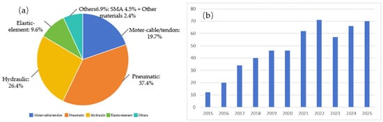
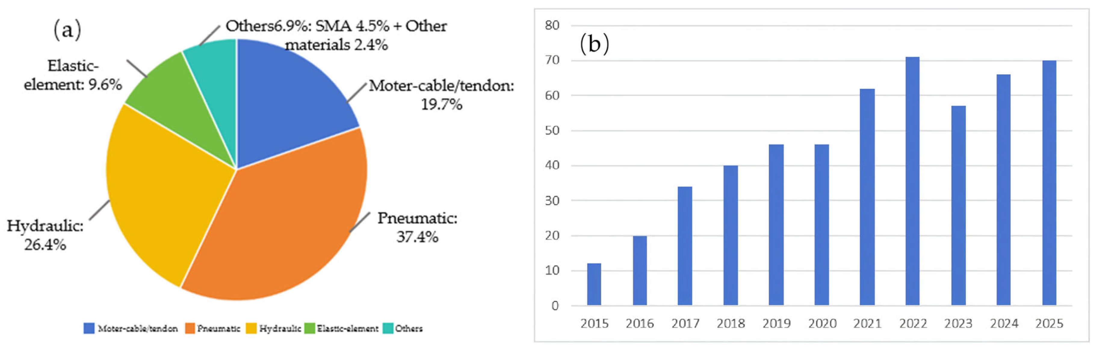
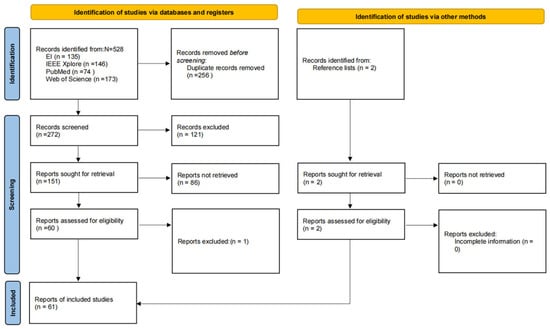
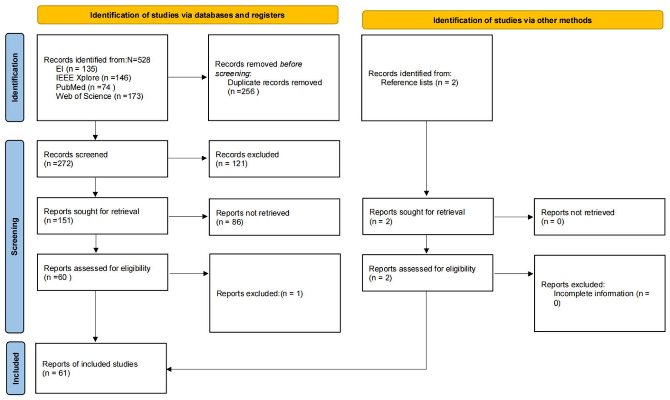
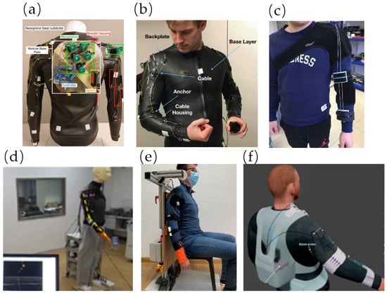
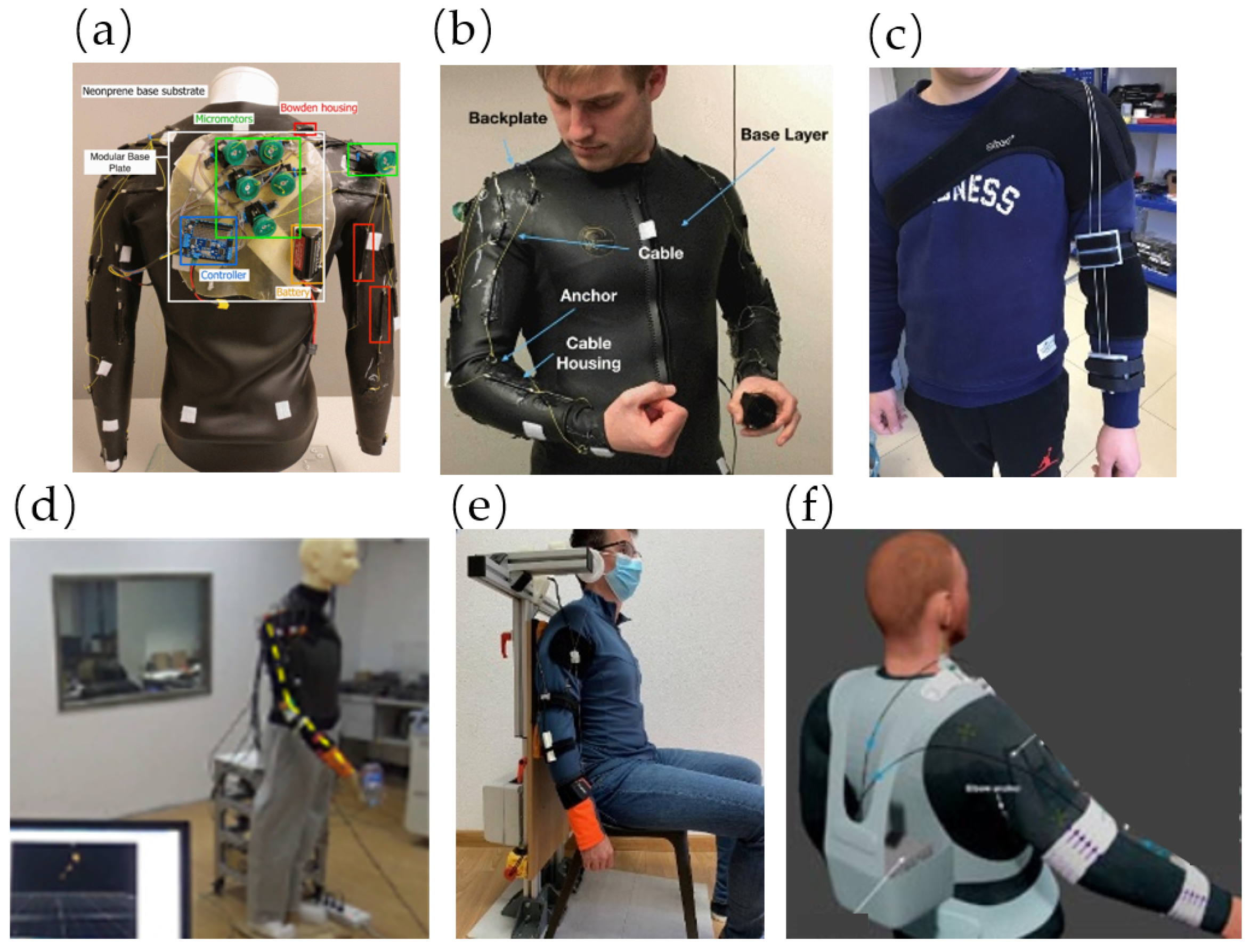
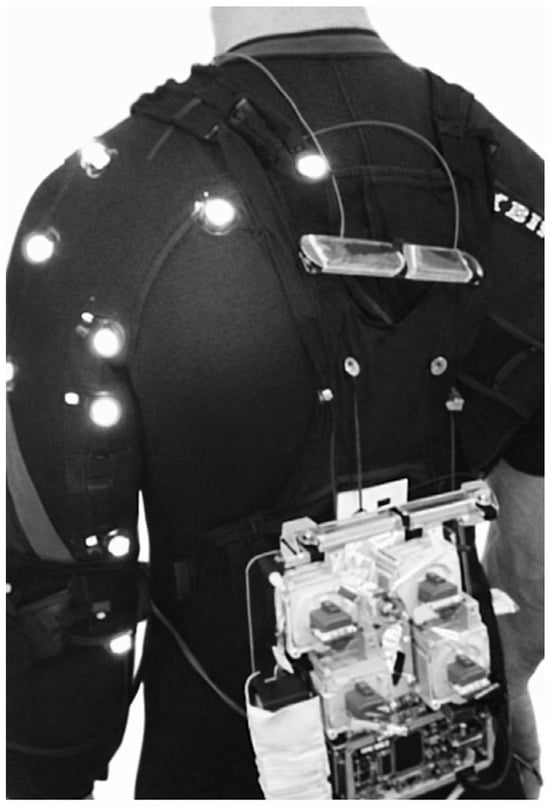
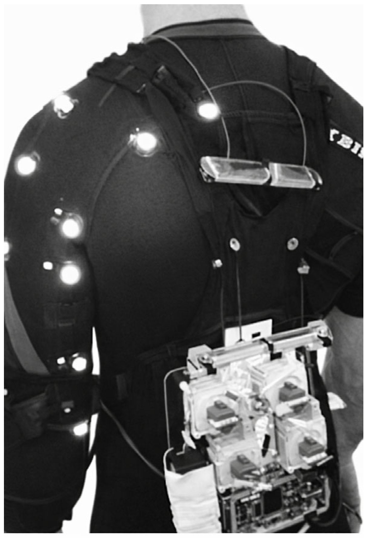
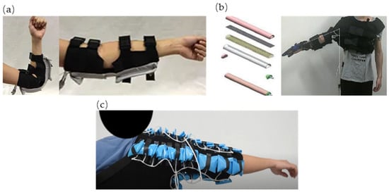
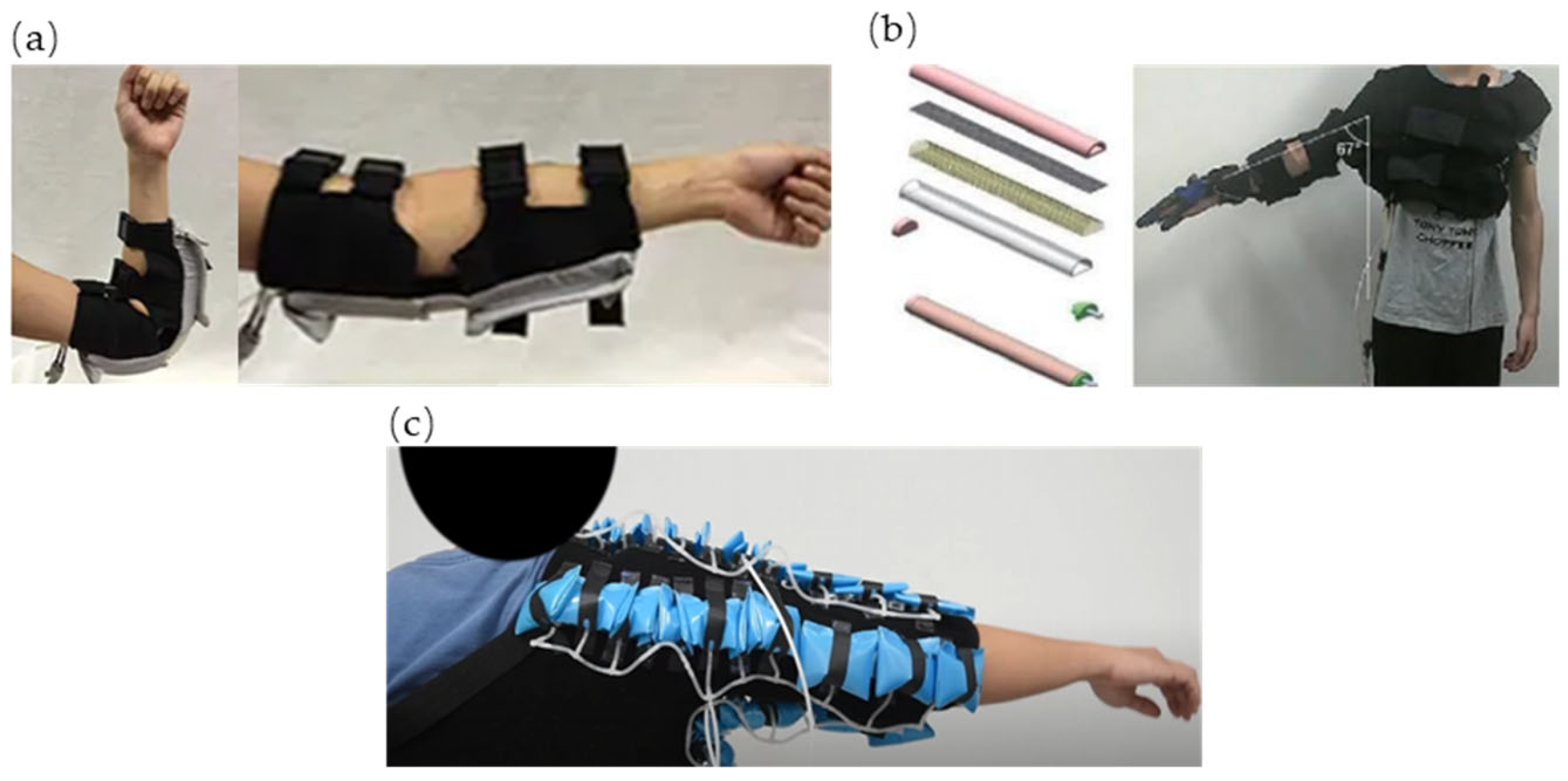
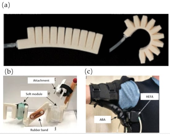
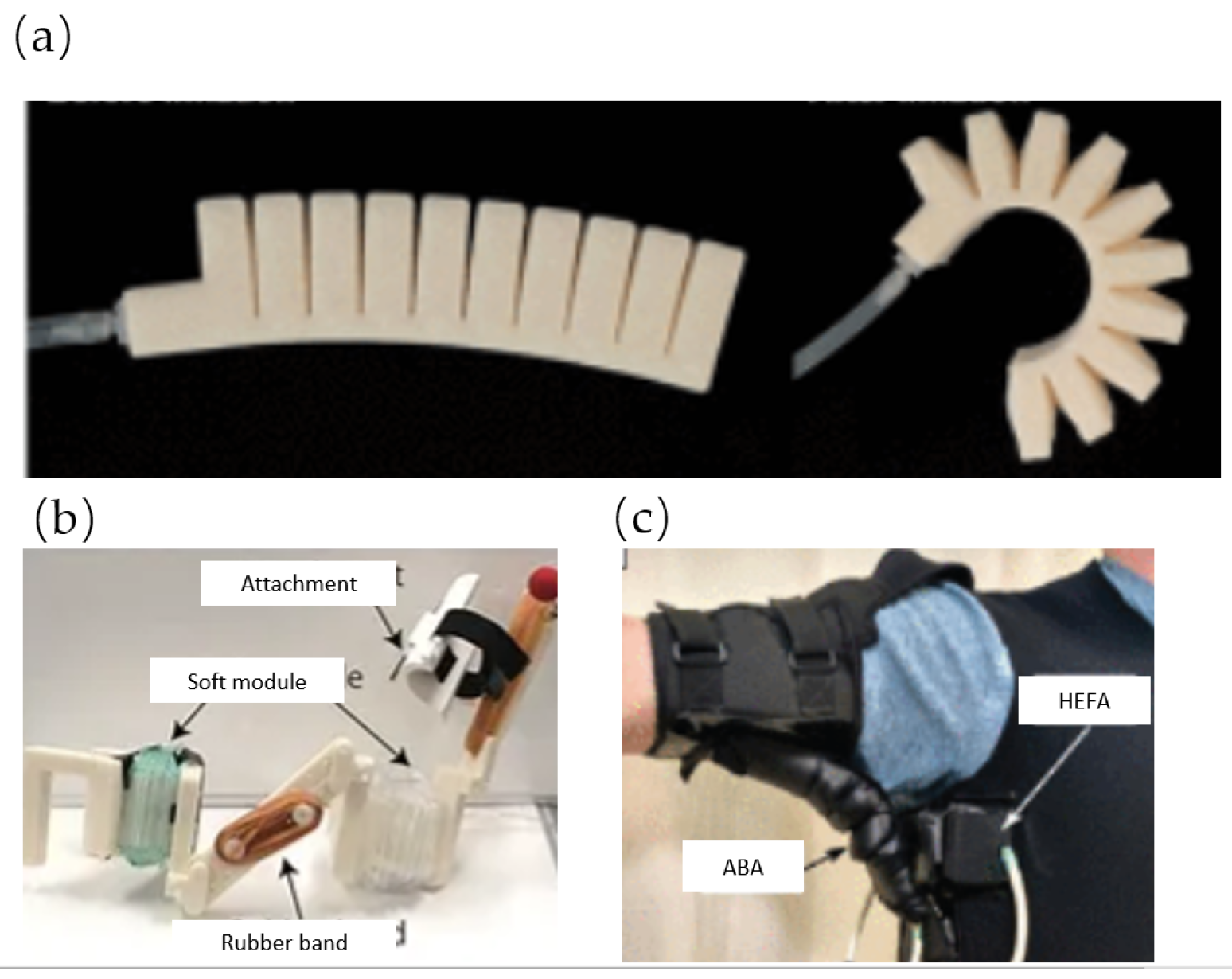
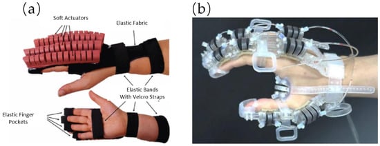
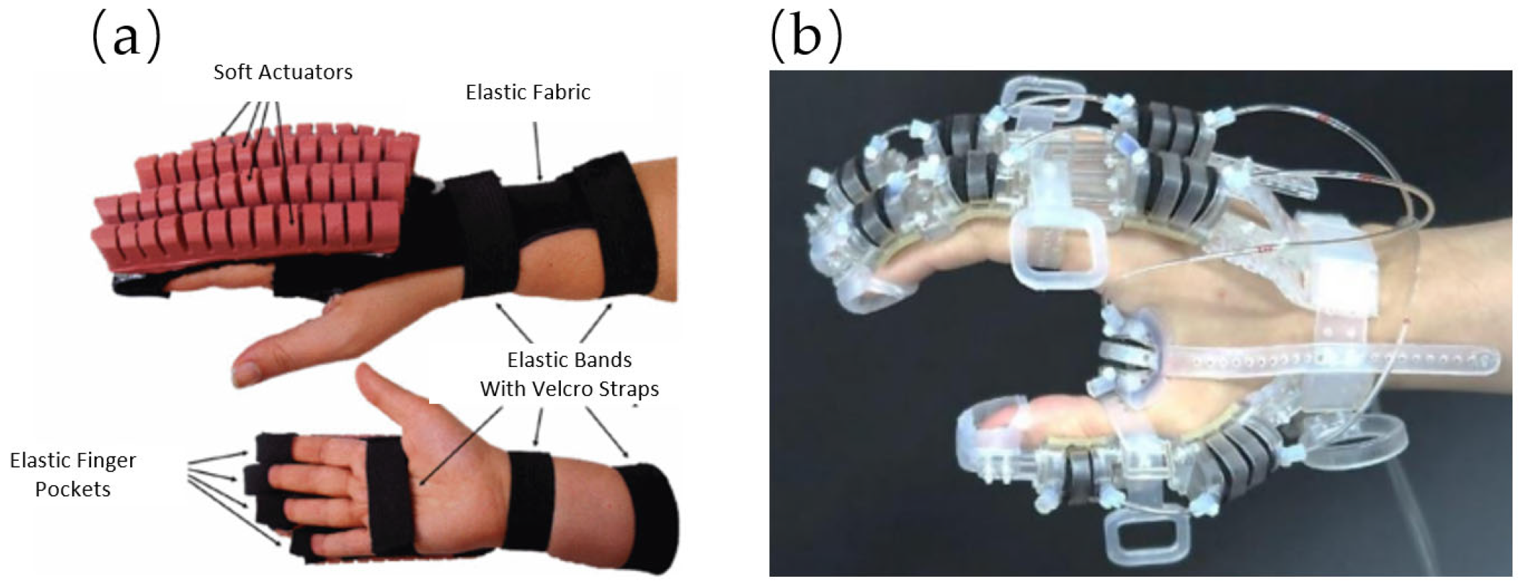
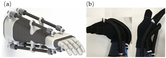
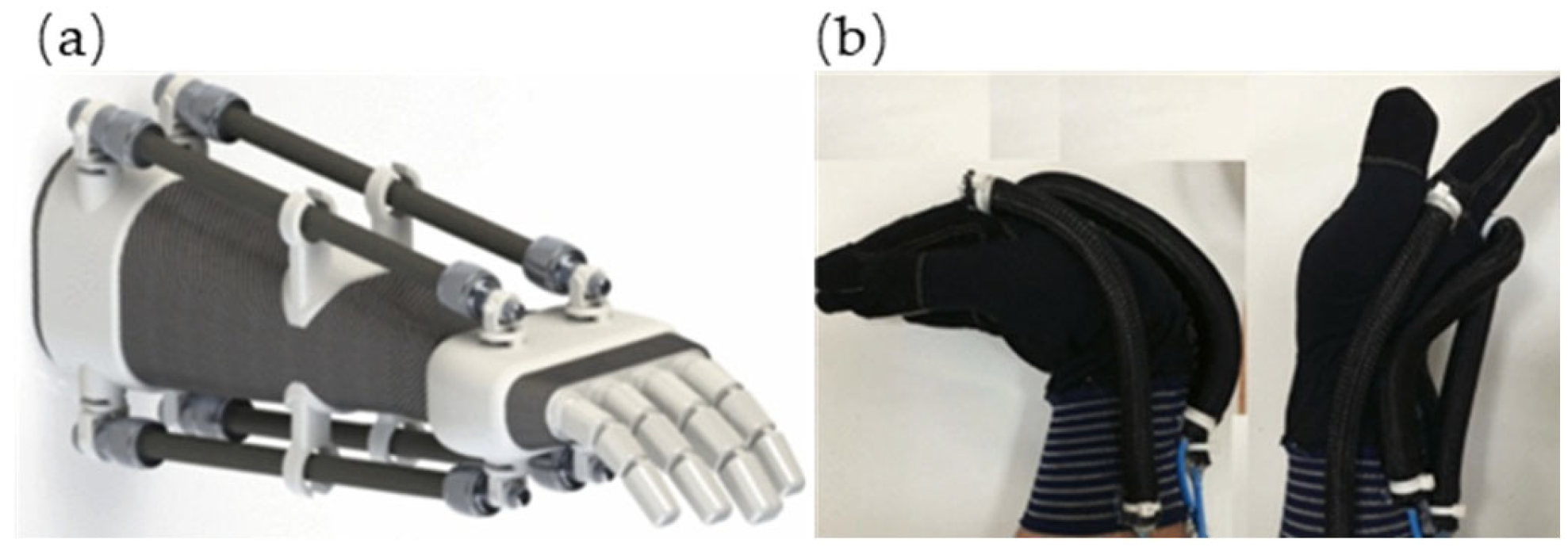
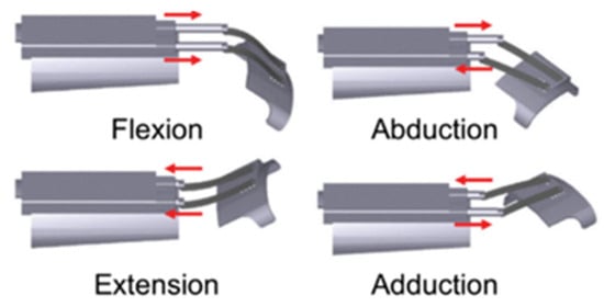
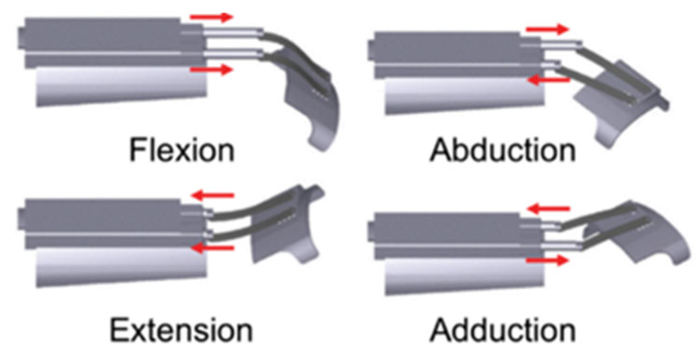
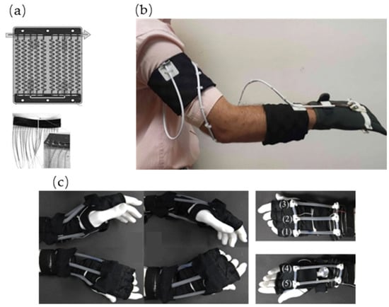
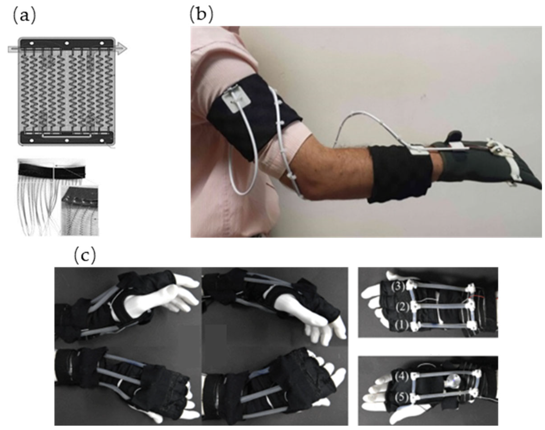

Disclaimer/Publisher’s Note: The statements, opinions and data contained in all publications are solely those of the individual author(s) and contributor(s) and not of MDPI and/or the editor(s). MDPI and/or the editor(s) disclaim responsibility for any injury to people or property resulting from any ideas, methods, instructions or products referred to in the content. |
© 2026 by the authors. Licensee MDPI, Basel, Switzerland. This article is an open access article distributed under the terms and conditions of the Creative Commons Attribution (CC BY) license.