


Abstract
PID control is widely adopted in fast-forging press hydraulic systems. However, it often fails to deliver satisfactory performance under variable operating conditions due to its fixed control parameters. To tackle this problem, this paper proposes a control strategy that combines digital twin (DT) technology with cascaded particle swarm optimization (PSO). In the outer-layer optimization, a twin model is first built in MATLAB/Simulink. By combining real-time sensor data with PSO, the outer-layer optimization identifies the optimal effective bulk modulus of the hydraulic oil. This procedure updates the twin model and enables real-time mapping between the twin model and the physical system. Based on the updated twin model, the inner-layer optimization employs PSO to tune the fractional-order PID (FOPID) controller parameters (Kp, Ki, Kd, λ, and μ) online. The optimal parameters are then applied to the physical system to enhance control performance. Experimental results show that, compared with single-layer PSO-FOPID control, the proposed strategy reduces settling time by 9.36% and overshoot by 2.216 percentage points under no-load conditions. Under loaded forging conditions, it reduces settling time by 12.7% and overshoot by 0.2 percentage points, thereby improving the system’s response speed and position-tracking accuracy.
1. Introduction
Fast-forging presses are heavy-duty machines used for metal forging and forming operations. Their high forging frequency, high degree of automation, superior control precision, and versatile processing capabilities have led to their widespread use in industries including aerospace, shipbuilding, automobile manufacturing, and metallurgy. Nevertheless, rapid advances in manufacturing technology and the aerospace sector have substantially increased the demand for high-quality forgings and for improved production efficiency. Therefore, improving the control performance of fast-forging presses has become a critical challenge in the forging industry [1,2,3]. PID control remains the dominant control scheme in most industrial applications. Although conventional PID controllers offer algorithmic simplicity and robustness, their fixed parameters make it challenging to achieve satisfactory control performance in fast-forging press hydraulic systems under time-varying operating conditions [4]. Therefore, it is essential to develop improved PID controller designs to enhance system performance under time-varying operating conditions.
Conventional PID control remains the most widely used approach in industrial hydraulic systems due to its simplicity and reliability. For example, Wrat et al. [5] applied a PID controller to compare two pump control strategies for hydraulic position systems: swash plate control of the main pump and speed control of the electric motor. They validated the results through MATLAB/Simulink modeling and experiments. However, the fixed parameters of conventional PID controllers remain a challenge when operating conditions vary significantly. To address this issue, Nguyen et al. [6] proposed an adaptive PID scheme based on a radial-basis-function (RBF) neural network implemented on an STM32 microcontroller. For the hydraulic servo systems of injection-molding machines, Hao et al. [7] employed the deep deterministic policy gradient (DDPG) algorithm for adaptive PID parameter tuning. Their method mitigated the degradation of position accuracy caused by system nonlinearities and external disturbances. To enhance the tracking precision of hydraulic servo systems under nonlinear and uncertain operating conditions, He et al. [8] proposed a PID tuning strategy based on the soft actor-critic (SAC) deep reinforcement learning algorithm. The approach comprises a high-level SAC module and a low-level PID controller for dynamic parameter adjustment. Shu et al. [9] optimized the parameters of a segmented PID control strategy using genetic algorithms, which effectively improved motion accuracy and suppressed speed fluctuations of the slider block in a 12,000 kN hydraulic fine-blanking press. To achieve fast convergence and strong robustness for proton exchange membrane fuel cell (PEMFC) power systems under varying temperatures and loads, Silaa et al. [10] designed an adaptive PID controller. This controller employs momentum-based stochastic gradient descent (SGDM) enhanced by the whale optimization algorithm (WOA). To improve PID controller performance, Li et al. [11] proposed a fuzzy-RBF-PID controller featuring fuzzy-rule-based adaptive learning rate tuning. This controller reduced tracking errors and enhanced the disturbance rejection capability of electro-hydraulic position servo systems subjected to abrupt load changes and stiffness variations. Zhang et al. [12] implemented fuzzy PID control based on AMESim-Simulink co-simulation to achieve multi-mode control of servo-motor-driven electro-hydraulic variable-displacement pumps. To address the performance degradation of conventional PID controllers under varying operating conditions in hydraulic turbine governing systems, Fu et al. [13] used a hybrid multi-objective Harris Hawks optimization (HMOHHO) algorithm to tune fractional-order PID (FOPID) parameters. To address nonlinearities in electro-hydraulic servo actuator systems, Fadel [14] developed a PSO-tuned hybrid sliding-mode PID (SMCPID) controller, which yielded better tracking performance and mitigated chattering effects. Jia et al. [15] proposed an integral-separation PID controller optimized by modified PSO (MPSO-IPID) to suppress large overshoot and shorten settling time for continuous position control (CPC) in steel-strip rolling lines.
Nevertheless, all of the aforementioned control strategies rely on offline parameter tuning based on simulation models. Since practical physical systems operate under complex, time-varying operating conditions, purely simulation-based models often cannot maintain sufficient fidelity in capturing the behavior of the physical system. Consequently, controller parameters tuned using such simulation models may become ineffective in real-world operation. Digital twin (DT) technology, which enables real-time bidirectional mapping and virtual-model-guided physical control, offers a promising approach to overcoming the aforementioned limitations. To improve the fidelity of permanent magnet synchronous motor (PMSM) digital twin models degraded by system non-stationarity, Xu et al. [16] employed a chain-splitting self-correcting Markov chain Monte Carlo (SC-MCMC) approach for autonomous Bayesian model updating. To improve the fidelity of real-time digital twins for steel bridge monitoring, Rabi and Monti [17] developed a genetic-algorithm-based model updating strategy. This strategy optimizes the elastic modulus of steel and minimizes discrepancies between measured modal parameters and simulation outputs. Chiscop et al. [18] constructed a digital twin model in WITNESS Horizon as a virtual commissioning platform for optimizing control strategies for automated brushless stator assembly lines. Their work eliminated key commissioning bottlenecks and increased per-shift throughput by 15.5%. To optimize adaptive control schemes for robotic manipulators, Zhao [19] developed a digital-twin-based virtual commissioning platform featuring bidirectional closed-loop mapping between the physical and virtual domains. A hybrid CNN-LSTM-Transformer neural network was integrated into this platform for real-time predictive optimization.
In summary, Xu et al. [16] and Rabi and Monti [17] employed various optimization algorithms for twin model updating, with an emphasis on improving fidelity, yet neither study extended their findings to practical control implementation. In contrast, Chiscop et al. [18] and Zhao [19] used digital twin models as virtual-commissioning platforms for offline controller-parameter tuning. Nevertheless, such offline tuning schemes exhibit poor adaptability to physical systems operating under complex time-varying conditions. To enhance the control performance of fast-forging press hydraulic systems under variable operating conditions, this paper proposes a control strategy that combines DT technology with a cascaded dual-layer PSO algorithm. The key advantage of the proposed strategy is its adaptability to time-varying operating conditions: the outer-layer performs real-time twin model updating by identifying the optimal effective bulk modulus of the hydraulic oil using real-time sensor data, while the inner-layer conducts online optimization of FOPID controller parameters using the updated twin model. The optimized parameters are then deployed to the physical system to improve control performance.
2. Framework Design of the Dual-Layer PSO Cascaded Optimization Strategy
2.1. Fast-Forging Press Hydraulic System
The fast-forging press hydraulic system mainly comprises the following key components: main cylinder, return cylinder, moving-crossbeam, upper anvil seat, lower anvil seat, two-way proportional flow-control cartridge valve, and hydraulic power unit. Figure 1 provides its simplified schematic diagram. The key control challenges of the hydraulic press are most pronounced during the fast-forging phase, where position accuracy is the primary control objective. This study focuses on this fast-forging phase of operation. During the pressing stroke, the main-cylinder inlet valve SV1 and the return-cylinder outlet valve SV4 operate in synchronization. High-pressure oil enters the main cylinder, and the return cylinder is connected to the system return line, which drives the moving-crossbeam downward. Meanwhile, the back-pressure valve PV regulates the system pressure to ensure safety. For the return stroke, the return-cylinder inlet valve SV3 and main-cylinder outlet valve SV2 open simultaneously. The main cylinder is linked to the system return line, and high-pressure oil is delivered to the return cylinder. As a result, the crossbeam moves upward and one full fast-forging cycle is completed [20].
Figure 1.
Simplified schematic diagram of fast-forging press.
2.2. Construction of a Simulation Test Platform for the Fast-Forging Press Hydraulic System
To simulate the pressing motion of a fast-forging press hydraulic system, a simulation test platform (Figure 2) was developed based on the system’s operating principles and available laboratory equipment. The platform consists of a hydraulic module and a measurement and control module. The hydraulic module includes a motor, a plunger pump, a twin gear pump, an electro-hydraulic servo valve, a single-rod hydraulic cylinder, a double-rod hydraulic cylinder, a relief valve, a force sensor, a pressure sensor, and a displacement sensor. The measurement and control module includes a host computer, a target machine, a servo amplifier, input terminals, and output terminals. The core of the platform consists of two servo-valve-controlled cylinder systems coupled through a force sensor. The servo system for the double-rod cylinder (Figure 2a) implements closed-loop displacement control to emulate the pressing motion of a fast-forging press. The single-rod-cylinder servo system performs closed-loop load-force control to simulate the loading force applied to the workpiece during forging.
Figure 2.
Simulation experiment platform for the fast-forging press hydraulic system. (a) Hydraulic module of the simulation platform. (b) Measurement and control module of the simulation platform.
2.3. Overall Framework Design
The proposed control strategy integrates DT technology with a cascaded optimization algorithm based on dual-layer PSO, in which PSO is used for both outer-layer and inner-layer optimization. The outer-layer optimization aims to enable real-time updating of the twin model, thereby providing a substantially improved virtual commissioning environment for optimizing the inner-layer FOPID controller. Using the updated twin model, the inner-layer process performs online optimization of the FOPID controller parameters. The optimized parameters are then deployed to the physical system for performance enhancement. These two layers form a cascaded structure, each corresponding to its own optimization objective. Figure 3 illustrates the overall framework.
Figure 3.
Overall framework for the dual-layer PSO cascaded optimization of the fast-forging press hydraulic system.
For the outer-layer optimization, a digital-twin model of the fast-forging press hydraulic system is first constructed. Subsequently, under the same reference displacement signal y0, sensor measurements from the physical system and virtual data from the digital-twin model are collected in real time. Next, the moving-crossbeam displacement and main-cylinder pressure from both datasets are selected as evaluation metrics. Based on these metrics, the PSO algorithm is used for online optimization of the effective bulk modulus of the hydraulic oil within the twin model. Through iterative evolution of the particle swarm, the effective bulk modulus value that best matches the physical system is identified. This optimized parameter is incorporated into the twin model to enable real-time model updating.
Inner-layer optimization is then performed on the updated twin model. Specifically, given the reference displacement signal y0, the virtual moving-crossbeam displacement output of the twin model is obtained in real time. The PSO algorithm then computes the real-time errors between the virtual displacement output and the reference signal y0. After sufficient particle iterations, the optimal set of five FOPID parameters (Kp, Ki, Kd, λ, and μ) is obtained, thereby enabling online tuning of the controller parameters. Finally, these optimal controller parameters are applied to the physical system of the fast-forging press. The detailed modeling procedures and the optimization algorithm are presented in Section 3 and Section 4, respectively.
3. Digital Twin Model Construction for the Fast-Forging Press Hydraulic System
This section introduces the core component—the two-way proportional flow-control cartridge valve—along with the mathematical model and digital twin model of the fast-forging press hydraulic system. The established models provide a solid foundation for the subsequent cascaded optimal control strategy based on dual-layer PSO.
3.1. Two-Way Proportional Flow-Control Cartridge Valve
The hydraulic system of the investigated fast-forging press employs an Atos two-way proportional flow-control cartridge valve for flow regulation. This valve is a pilot-operated proportional throttle valve with electrical displacement feedback, as illustrated in Figure 4. The pilot stage of this valve can be simplified to a closed-loop displacement-controlled valve-controlled cylinder configuration. In this configuration, the proportional pilot valve serves as the control element, while the main valve spool functions as the controlled double-acting cylinder. In Figure 4, Ps1 represents the supply pressure of the main circuit in the fast-forging press hydraulic system, while Ps2 represents the supply pressure of the pilot circuit. When the spool of the proportional pilot valve remains at the position shown in Figure 4, high-pressure oil from the pilot circuit flows into chamber E of the main valve while chamber D is connected to the return line. This drives the main-valve spool upwards. When the proportional pilot valve reverses its spool direction, high-pressure oil from the pilot circuit flows into chamber D of the main valve, and chamber E is connected to the return line, which drives the main-valve spool downward.
Figure 4.
Simplified schematic diagram of the two-way proportional flow-control cartridge valve.
The main valve stage of the two-way proportional flow-control cartridge valve essentially operates as a two-way cartridge valve. It adjusts the main valve orifice opening by varying the main spool displacement. As presented in Figure 4, the main-valve spool has a hollow structure. Chambers A and C are linked via an internal through-hole; hence, pressures within chambers A and C remain identical. This structural design ensures that the forces exerted on the main valve spool by the main hydraulic circuit are nearly balanced [21]. When no flow is needed in the main circuit, the main valve spool moves downward to close the orifice of chamber A, resulting in zero flow rate Qa in the main circuit. In contrast, when flow is required, the main-valve spool shifts upwards; the orifice of chamber A opens proportionally, generating flow Qa in the main circuit. The orifice flow area can be adjusted by varying the main spool displacement, thereby enabling flow regulation in the main hydraulic circuit.
The displacement control process of the fast-forging press hydraulic system comprises two closed loops: one for main valve spool displacement, driven by the proportional pilot valve, and another for moving-crossbeam displacement, driven by the main valve spool. In the pilot-stage displacement control loop, the main-spool displacement x is measured by a displacement sensor and fed back to the pilot-valve controller. Based on the error between the reference signal x0 and the feedback displacement x, the controller generates the control signal I for the proportional pilot valve. The proportional solenoid precisely adjusts the displacement of the pilot valve spool to control the magnitude and direction of the output flow, thereby achieving closed-loop control of the main spool displacement.
For closed-loop control of the moving-crossbeam displacement, the hydraulic-press controller compares reference displacement y0 with measured moving-crossbeam displacement y and generates reference signal x0 for main-spool displacement. After the pilot-stage closed-loop regulation, the main spool reaches the desired displacement. This displacement then adjusts the main-valve orifice opening, thereby changing the flow area and ultimately achieving closed-loop control of the moving-crossbeam displacement.
3.2. Mathematical Modeling of the Fast-Forging Press Hydraulic System
3.2.1. Mathematical Model of the Pilot Section of the Two-Way Proportional Flow-Control Cartridge Valve
In Section 3.1, the pilot section of the two-way proportional flow-control cartridge valve was simplified to a valve-controlled cylinder configuration. Based on this configuration, the mathematical model of the proportional pilot valve-controlled cylinder is developed as follows.
The following assumptions are made for the pilot stage: (1) the flow direction of hydraulic oil from the proportional pilot valve to the main valve spool chamber is defined as positive, as shown in Figure 4; (2) upward movement of the proportional pilot valve spool is defined as positive; and (3) internal leakage in the proportional pilot valve is neglected. Under these assumptions, the flow equation for the proportional pilot valve orifice is as follows:
where Qe is the flow rate at port E of the proportional pilot valve; Qd is the flow rate at port D of the proportional pilot valve; Cd is the flow coefficient of the valve orifice; Ps2 is the supply pressure of the pilot circuit; Pt is the return pressure of the pilot circuit; Pe is the pressure in chamber E of the main valve; Pd is the pressure in chamber D of the main valve; ρ is the density of the hydraulic oil; S is the flow area of the valve orifice; and when the spool of the proportional pilot valve moves in the positive direction, S is positive.
The spool displacement in the proportional pilot valve is determined by the input electrical signal. As the spool moves, the orifice flow area changes accordingly; the relationship between them is given by:
where u is the electrical input signal to the proportional pilot valve, and k1, k2, k3 and k4 are the voltage to orifice-area gain coefficients. These coefficients were obtained experimentally as follows. For the proportional pilot valve of the two-way proportional flow-control cartridge valve, the pressure differential across the valve was set to 4 MPa according to the actual working conditions. Forty sets of data on input voltage versus regulated flow were measured at equal intervals over the input signal range of −10 V to 10 V. The corresponding valve-orifice flow areas were then calculated from the measured flow rates using the orifice flow equation (Equation (1)). The resulting 40 sets of voltage–orifice-area data were imported into the MATLAB Curve Fitting Toolbox (cftool) for cubic polynomial fitting, which yielded Equation (4). The fitted voltage–orifice-area curve is shown in Figure 5.
S = k1u3 + k2u2 + k3u + k4
Figure 5.
Voltage–orifice area characteristic of the proportional pilot valve. The blue circles represent experimentally measured data points, and the red solid curve is the cubic polynomial fit obtained using the MATLAB Curve Fitting Toolbox (cftool).
When hydraulic oil enters the main valve spool chamber under the control of the proportional pilot valve, the main valve spool investigated in this study can be treated as a double-acting piston cylinder. Neglecting external leakage from the main valve spool chamber and assuming that the direction of hydraulic oil flow into the main valve chamber is positive, the flow continuity equation is:
where A is the effective acting area of the main valve spool; x is the displacement of the main valve spool; Cip is the internal leakage coefficient; βe is the effective bulk modulus of the hydraulic oil; Ve is the volume of chamber E in the main valve; and Vd is the volume of chamber D in the main valve.
The volumes of the two chambers of the main valve do not remain constant during operation; they change as the main valve spool moves. The relationship is as follows:
where Ve0 and Vd0 are the initial volumes of chambers E and D in the main valve spool, respectively.
For the force analysis of the main valve spool, the force balance equation is established based on Newton’s second law:
where m is the equivalent mass of the main valve spool; B is the viscous damping coefficient of the hydraulic oil; K is the elastic stiffness of the load; and Fl is the external load force.
3.2.2. Mathematical Model of the Main Valve Stage of the Two-Way Proportional Flow-Control Cartridge Valve
In this study, the main valve section of the two-way proportional flow-control cartridge valve adjusts the opening of the main valve orifice by regulating the displacement of the main valve spool. The flow calculation equation for chamber A of the main valve orifice is:
where Qa is the flow rate through chamber A of the main valve; w is the area gradient of the main valve port; Ps1 is the supply pressure of the main circuit; Pb is the pressure in chamber B of the main cylinder.
The flow through chamber A of the main valve ultimately enters the main cylinder and return cylinder of the fast-forging press. Neglecting external leakage from the hydraulic cylinders and defining downward movement of the moving-crossbeam as positive, the flow continuity equations for the main cylinder and return cylinder are as follows (chamber B corresponds to the main cylinder, and chamber F corresponds to the return cylinder):
where Qb is the flow rate entering the main cylinder through chamber A of the main valve; Qf is the flow rate entering the return cylinder through chamber A of the main valve; A1 is the area of the main cylinder plunger; A2 is the area of the return cylinder plunger; y is the displacement of the moving-crossbeam; Vb is the volume of chamber B in the main cylinder; Vf is the volume of chamber F in the return cylinder; and Pf is the pressure in chamber F of the return cylinder.
The volume changes in the main cylinder and return cylinder are related as follows:
where Vb0 and Vf0 are the initial volumes of chamber B in the main cylinder and chamber F in the return cylinder, respectively.
3.2.3. Mathematical Model of the Actuator
The actuator of the fast-forging press consists of a main cylinder and a return cylinder, which are connected to the moving-crossbeam. Hydraulic force drives the moving-crossbeam to perform reciprocating motion to complete fast forging operations. The force-balance equation is:
where G is the weight of the moving part of the hydraulic press, M is its mass, FL is the external load acting on the moving part, and Ff is the friction force acting on the moving part.
3.3. MATLAB/Simulink Twin Modeling of the Fast-Forging Press Hydraulic System
During operation of the fast-forging press hydraulic system, time-varying system parameters induced by complex working conditions reduce the fidelity of simulation models. Controller parameters tuned using low-fidelity offline simulation models may fail when deployed in practice. To resolve this problem, this study constructs a digital twin model in MATLAB/SimulinkR2021b based on the mathematical equations derived above, and establishes virtual-to-physical mapping with the physical system. This provides a model foundation for the outer-layer twin model updating within the proposed dual-layer PSO cascaded optimization strategy.
3.3.1. Twin Model of the Pilot Section of the Fast-Forging Press Hydraulic System
Based on Equation (4), the flow area S of the proportional pilot valve is calculated from the input electrical signal u. By combining this result with the orifice flow formula in Equation (1), the twin model is constructed for the proportional pilot valve. This module takes valve-orifice flow area S and pressure difference △P as inputs and outputs port-E flow Qe and port-D flow Qd. Figure 6 presents the twin-model subsystem for port-E flow calculation of the proportional pilot valve.
Figure 6.
Twin model of the flow rate at port E of the proportional pilot valve.
The main-valve spool serves as the actuator for the pilot-valve-controlled cylinder system. According to flow-continuity relationships shown in Equation (5), twin-model subsystems are built, which take flow rate, main-spool velocity v and main-spool displacement x as inputs and output chamber-E pressure Pe and chamber-D pressure Pd. Figure 7 illustrates the pressure-calculation subsystem for main-valve chamber E; the subsystem for chamber D follows identical logic. Further, the force-balance twin model for the main-valve spool (Figure 8) is constructed according to Equation (7), and outputs main-spool velocity v and displacement x.
Figure 7.
Twin model of the pressure in chamber E of the main valve.
Figure 8.
Force balance twin model of the main valve spool.
3.3.2. Twin Model of the Main Valve Section of the Fast-Forging Press Hydraulic System
The main-spool displacement is already obtained from the pilot-stage twin subsystems. The main-valve-stage twin model takes main-spool displacement as input and outputs main-valve-port flow and pressure. According to the orifice-flow formula Equation (8), the twin-model subsystem for main-valve port-A flow is established, with main-spool displacement x and main-circuit supply pressure Ps1 as inputs and orifice flow Qa as output (Figure 9).
Figure 9.
Twin model of the flow rate at port A of the main valve.
When the hydraulic-press main cylinder operates, oil flows into the main cylinder via main-valve port A. For the main cylinder, the twin-model subsystem is built based on Equation (9). It receives main-cylinder inflow Qb, moving-crossbeam velocity v and displacement y as inputs and outputs main-cylinder chamber-B pressure Pb, as shown in Figure 10. Based on this, the force-balance twin subsystem for the entire hydraulic press (Figure 11) is developed from Equation (11) and outputs moving-crossbeam displacement.
Figure 10.
Twin model of the pressure of the main cylinder.
Figure 11.
Force balance twin model of the fast-forging press.
3.3.3. Overall Twin Model of the Fast-Forging Press Hydraulic System
Based on the pilot-stage and main-valve-stage twin model subsystems described above, the overall twin model of the fast-forging press hydraulic system is constructed by encapsulating and connecting the preceding twin model subsystems. To achieve dual closed-loop displacement control, a conventional PID controller is adopted for the closed-loop regulation of the pilot-stage main spool displacement. At the main control level, an FOPID controller is employed for the closed-loop control of the press displacement. Details of the FOPID controller are provided in Section 4. The complete topology of the twin model is shown in Figure 12, and the key model parameters are summarized in Table 1. It should be noted that the geometric and physical parameters in Table 1 are measured or calculated from the physical fast-forging press system. The voltage to orifice area coefficients k1–k4 are obtained through experimental curve fitting of the proportional pilot valve, as described in Section 3.2.1. Among these parameters, the effective bulk modulus of the hydraulic oil βe is identified as the key time-varying parameter considered in this study; rather than being fixed, it is online identified and updated using real-time sensor data through the outer-layer PSO, as detailed in Section 4.2.
Figure 12.
Overall twin model of the fast-forging press hydraulic system.
Table 1.
Main parameters of the twin model for the fast-forging press hydraulic system.
4. Cascaded Optimization of the Fast-Forging Press Hydraulic System Using a Dual-Layer PSO Algorithm
4.1. Theoretical Foundations of the FOPID Controller and the PSO Algorithm
4.1.1. Foundations of the FOPID Controller
As an extension of conventional PID, the FOPID controller introduces two additional tunable parameters: the integral order λ and the derivative order μ. These parameters provide additional degrees of freedom for optimizing the dynamic performance of the fast-forging press hydraulic system. The integral order λ and the derivative order μ can be any real numbers in the range [0, 2]. FOPID reduces to a standard PID controller when λ = 1 and μ = 1 [22].
The basic operator in fractional calculus is of the form t0, which is defined as follows:
where t and t0 are the upper and lower limits of integration, respectively. When α > 0, t0 represents a fractional-order differential operator; when α = 0, t0 = 1; and when α < 0, t0 represents a fractional-order integral operator.
There are two main definitions of fractional calculus: the Riemann–Liouville (R–L) definition and the Grünwald–Letnikov (G–L) definition. Because the Grünwald–Letnikov definition is better suited to numerical implementation, it is adopted in this work. The G–L expression is:
where [] denotes the floor function; h is the calculation step size; bj is the binomial coefficient, with b0 = 1 and .
The transfer function of the FOPID controller is:
Gc = Kp + Kis−λ + Kdsμ
In the time domain, the FOPID controller is expressed as follows:
where e(t) is the tracking error of the controller; is the fractional-order integral operator; and is the fractional-order differential operator.
To apply the FOPID controller to a discrete-time system, the G–L definition in Equation (13) is substituted into Equation (15) for discrete-time numerical solution, ultimately yielding the discrete-time control algorithm of the FOPID controller [23]:
4.1.2. Theoretical Foundations of the PSO Algorithm
Particle swarm optimization (PSO) is a population-based metaheuristic inspired by the foraging behavior of bird flocks. Its iterative update process can be viewed as a search for the optimal solution within the feasible solution space, achieved through collaboration and information exchange among individuals in the swarm [24].
In the PSO algorithm, each particle has two basic attributes: position X and velocity V. The position X characterizes the coordinates of the particle within the feasible solution space, while the velocity V represents the direction and distance of the particle’s motion. In a particle swarm consisting of N particles in a d-dimensional search space, the position Xi and velocity Vi of each particle are expressed as follows:
Xi = (xi1, xi2, xi3, …, xid), i = 1, 2, 3, …, N.
Vi = (vi1, vi2, vi3, …, vid), i = 1, 2, 3, …,N.
During the execution of the PSO algorithm, each particle continuously approaches the optimal position, i.e., the position with the best fitness. Fitness serves as the key metric for evaluating the quality of a particle’s position. It is generally defined as the system output error corresponding to each particle’s position; a smaller fitness value indicates a better particle solution. In each iteration, the best solution found by an individual particle is called the personal best (pbest), and the best solution found by all particles in the swarm is called the global best (gbest). Particles update their velocities and positions based on these two optima, using the following update equations [25]:
where i = 1, 2, 3, …, N; k is the iteration number; ω is the inertia weight; c1 is the individual learning factor; c2 is the population learning factor; r1 and r2 are two random numbers in the interval [0, 1]; d is the particle dimension, which corresponds to the number of parameters to be optimized; is the velocity of the i-th particle in the d-dimensional space after the k-th iteration; is the position of the i-th particle in the d-dimensional space after the k-th iteration; pbestd is the d-th dimensional position of the individual optimum in the particle swarm; and gbestd is the d-th dimensional position of the global best in the particle swarm.
4.2. Optimization and Update of the Digital Twin Model Based on the PSO Algorithm
This section presents the optimization and update of the twin model for the fast-forging press hydraulic system. Among the parameters listed in Table 1, the effective bulk modulus of the hydraulic oil βe is identified as the key time-varying parameter. The effective bulk modulus varies with the number of hydraulic hoses, the oil temperature, and the pressure during actual operation. The approach combines the PSO algorithm with real-time sensor data to identify the optimal effective bulk modulus online. The optimized value is then incorporated into the twin model of the fast-forging press hydraulic system, thereby updating the model in real time. This online identification and model-updating procedure, driven by real-time pressure and displacement measurements from the physical system, constitutes the real-time data interaction between the digital twin and the physical entity. The main parameter settings of the PSO algorithm in this section are listed in Table 2.
Table 2.
Key parameters of the PSO algorithm for the outer-layer optimization.
Particle fitness is computed as the root-mean-square error between the physical and twin values of main-cylinder pressure and moving-crossbeam displacement of the fast-forging press hydraulic system. Since main-cylinder pressure is more sensitive to variations in the effective bulk modulus of the hydraulic oil, a higher weighting coefficient of 0.8 is assigned to the pressure term in the fitness function. The fitness function of the PSO algorithm is:
where n is the number of sampling points; j is the sampling index; the sampling frequency of the twin model of the fast-forging press hydraulic system is 1000 Hz; Pbj is the pressure signal of chamber B of the main cylinder acquired at time j; is the pressure twin signal output by the twin model at time j, which can be calculated from Equation (9) in the twin modeling; yj is the displacement signal of the moving-crossbeam acquired at time j; and is the displacement twin signal output by the twin model at time j, which can be calculated from Equation (11) in the twin modeling. Minimizing reduces the discrepancy between the physical system and its twin model. The corresponding particle position yields the optimal value of the effective bulk modulus of the hydraulic oil.
Figure 13 presents a flowchart of the parameter optimization process for the fast-forging press hydraulic system based on the PSO algorithm. The parameter optimization process is as follows: First, a particle swarm of N individuals is randomly initialized within predefined boundary ranges. Then, each particle’s position value is assigned to the effective bulk modulus of the hydraulic oil in the twin model. Subsequently, the main-cylinder pressure and moving-crossbeam displacement of the physical press are sampled in real time, and the twin model is executed for simulation. The fitness of each particle is calculated using Equation (21), and the current iteration count is recorded. Finally, the algorithm checks whether the current iteration number has reached the maximum. If so, the loop terminates, and the particle with the lowest fitness represents the optimal solution for the effective bulk modulus. If not, particle velocities and positions are updated according to Equations (19) and (20), and the optimization process repeats until the termination condition is met.
Figure 13.
Flowchart of parameter optimization in the outer-layer optimization of the fast-forging press hydraulic system.
The PSO algorithm is used to optimize this parameter, and the convergence process is shown in Figure 14. As shown in the figure, the effective bulk modulus of the hydraulic oil starts from an initial value of 1080 MPa and converges after the 8th iteration. After 20 iterations, the optimal value of the effective bulk modulus is determined to be 342.7 MPa. This optimized value is then incorporated into the twin model, and the updated model serves as the virtual commissioning environment for the inner-layer optimization in the next section.
Figure 14.
Optimization process of the effective bulk modulus of the hydraulic oil in the fast-forging press hydraulic system.
4.3. Online Optimization of FOPID Controller Parameters Based on the PSO Algorithm
This section presents the online parameter optimization of the FOPID controller for the inner-layer of the fast-forging press hydraulic system. Based on the updated twin model of the fast-forging press hydraulic system, online parameter optimization is carried out in a five-dimensional feasible solution space, where the five FOPID controller parameters (Kp, Ki, Kd, λ, and μ) define the five dimensions of a single particle. Ultimately, the optimal FOPID controller parameters obtained through this optimization are applied to the physical system to improve its control performance. The main parameter settings of the PSO algorithm are listed in Table 3.
Table 3.
Key parameters of the PSO algorithm for the inner-layer optimization.
During PSO-driven FOPID parameter optimization, each particle is represented as a 1 × 5 vector containing the five tunable FOPID controller parameters. The key metric for evaluating the quality of a particle’s position is its fitness. The fitness of the i-th particle is calculated as follows:
where y0 is the reference displacement signal in the twin model of the fast-forging press hydraulic system. The root-mean-square error between the twin displacement signal and the reference signal is computed in real time at each time step to evaluate the quality of the FOPID controller parameters. A minimum corresponds to optimal control performance of the twin model, and the associated particle position yields the optimal set of FOPID controller parameters.
Figure 15 shows the flowchart of the FOPID controller parameter optimization based on the PSO algorithm. The parameter optimization process is as follows: First, a swarm of N particles is randomly generated within the specified particle boundary range. Then, the position of each particle (a 1 × 5 matrix) is sequentially assigned to the five parameters of the FOPID controller: Kp, Ki, Kd, λ, and μ. Next, the twin model of the fast-forging press hydraulic system is run, and the fitness of each particle is calculated according to Equation (22), with the current iteration count recorded. Finally, the algorithm checks whether the current iteration count has reached the maximum number of iterations; if so, the loop is terminated, and the position of the particle with the lowest fitness in the swarm corresponds to the optimal set of the five FOPID controller parameters. If the current iteration number has not yet reached the maximum number of iterations, the particle swarm updates its velocities and positions according to Equations (19) and (20), generates a new particle swarm, and repeats the above optimization process.
Figure 15.
Flowchart of parameter optimization in the inner-layer optimization of the fast-forging press hydraulic system.
Over the 20 PSO iterations, the particle fitness gradually decreases, indicating that the particle positions converge progressively toward the optimal solution. The variation in particle fitness during the iterative process is shown in Figure 16. As shown in the figure, the particle fitness decreases sharply in the first five iterations and stabilizes by the 16th iteration, beyond which the five FOPID controller parameters (Kp, Ki, Kd, λ, and μ) remain essentially constant until the end of the 20 iterations. The optimal solutions for the five FOPID controller parameters are Kp = 4.6507, Ki = 1.3214, Kd = 0.531, λ = 0.6829, and μ = 0.6085. The variation curves of the controller parameters during the iterative process are shown in Figure 17.
Figure 16.
Variation in particle fitness during the inner-layer PSO.
Figure 17.
Variation in FOPID controller parameters. (a) Variation curve of parameter Kp. (b) Variation curve of parameter Ki. (c) Variation curve of parameter Kd. (d) Variation curve of parameter λ. (e) Variation curve of parameter μ.
4.4. Simulation Verification
This section presents simulation studies based on the digital twin model of the fast-forging press hydraulic system to validate the proposed control strategy. The simulation work is divided into two parts: (1) twin model validation, where the correctness of the twin model established in Section 3.3.3 is verified by examining its displacement and pressure responses under a step input; and (2) position tracking control simulations, where the control performance of three controllers—the conventional PID, the single-layer PSO-FOPID, and the proposed dual-layer PSO-FOPID—is compared under both the no-load downward stroke and the downward forging stroke conditions.
4.4.1. Twin Model Validation
Position tracking simulations under a step input signal are conducted on the twin model of the fast-forging press hydraulic system established in Section 3.3.3 to validate its correctness. A step displacement command jumping from 1.5 m to 2 m is applied at t = 4 s, and the displacement tracking response as well as the pressure variations in the main cylinder and return cylinder chambers are recorded.
Figure 18a shows the displacement tracking curve of the twin model under the step input. As can be seen from the figure, under conventional PID control, the system is able to track the step displacement command and the output displacement eventually reaches the target value of 2 m. However, the step response exhibits relatively poor dynamic performance, including noticeable overshoot and a long settling time. This is because the fixed-parameter PID controller cannot fully accommodate the nonlinear characteristics of the fast-forging press hydraulic system, such as the nonlinear pressure-flow relationship of the valve orifice and the time-varying effective bulk modulus of the hydraulic oil, which limits the control performance.
Figure 18.
Step response of the twin model. (a) Position tracking. (b) Cylinder pressure variations.
Figure 18b presents the pressure variation curves of the main cylinder chamber (chamber B) and the return cylinder chamber (chamber F) during the step response. Before the step command (t < 4 s), the system operates at the initial position of 1.5 m, and the pressures in both cylinder chambers remain at their steady-state values. At the moment of the step command (t = 4 s), the reference displacement jumps from 1.5 m to 2 m, causing the two-way proportional flow-control cartridge valve to open rapidly. As a result, high-pressure oil from the supply line flows into the main cylinder chamber, and the main cylinder pressure jumps abruptly to the system supply pressure of 27 MPa. Meanwhile, the return cylinder is connected to the system return line, and the return cylinder pressure drops rapidly and approaches 0 MPa. The large pressure difference between the two chambers provides the driving force that accelerates the moving-crossbeam downward. During the period of approximately 5 s to 8 s, the pressures in both cylinders fluctuate significantly, because the hydraulic press is rapidly adjusting the displacement of the moving-crossbeam during this phase. These pressure variation patterns are consistent with the operating principles of the fast-forging press hydraulic system described in Section 2.1, confirming that the established twin model correctly captures the dynamic behavior of the physical system and provides a reliable foundation for the subsequent controller parameter optimization.
The relatively poor step response performance of the conventional PID controller demonstrates the necessity for advanced control strategies with better parameter tuning capability. The following subsections further compare the control performance of the single-layer PSO-FOPID and the proposed dual-layer PSO-FOPID strategies through simulation studies.
4.4.2. Position Tracking Simulation During the No-Load Downward Stroke
To compare the control performance of different controllers under no-load conditions, step position tracking simulations are conducted for the no-load downward stroke. A step displacement command jumping from 1.5 m to 2 m is applied at t = 4 s, and three controllers are compared: the conventional PID, the single-layer PSO-FOPID, and the proposed dual-layer PSO-FOPID.
Figure 19a shows the step position tracking curves of the three controllers. All three controllers are able to achieve position tracking of the 0.5 m step command, but their dynamic performance differs significantly. The conventional PID controller exhibits the slowest response speed and the largest overshoot. The single-layer PSO-FOPID controller achieves better performance than the conventional PID. The fractional-order structure provides additional degrees of freedom for controller design, and the PSO algorithm enables automatic parameter tuning, which together improve both the dynamic and steady-state performance. However, since the single-layer strategy optimizes the FOPID parameters based on the initial twin model without model updating, a certain mismatch remains between the optimized parameters and the actual system behavior, which limits the further improvement of control performance. The dual-layer PSO-FOPID controller, which combines outer-layer twin model updating and inner-layer FOPID parameter optimization, achieves the best tracking performance among the three controllers, with the fastest response speed and the smallest overshoot.
Figure 19.
Simulation results of step position tracking during the no-load downward stroke. (a) Position tracking curves. (b) Step response error curves.
Figure 19b presents the step response error curves of the three controllers, providing a more intuitive comparison of the transient and steady-state performance, and the performance difference among the three controllers is most obvious at the moment when the step command occurs. The conventional PID controller exhibits the largest peak error and the slowest error convergence speed. The single-layer PSO-FOPID reduces both the peak error and the settling time compared with the conventional PID. The dual-layer PSO-FOPID achieves the smallest peak error and the fastest error convergence, further demonstrating the advantage of the proposed cascaded optimization framework. In addition, the steady-state error of the dual-layer PSO-FOPID is significantly lower than that of the other two controllers, indicating higher steady-state control accuracy. The quantitative performance comparison under the no-load downward stroke condition is summarized in Table 4.
Table 4.
Comparison of simulation control performance under the no-load downward stroke condition.
4.4.3. Position Tracking Simulation During the Downward Forging Stroke
To further evaluate the control performance under loaded conditions, step position tracking simulations are performed on the twin model of the fast-forging press hydraulic system. A forging load of 18,000,000 N is applied to the moving-crossbeam to simulate the practical forging process, and the step response of the three controllers is compared under the same 1.5 m to 2 m step command.
Figure 20a shows the step position tracking curves of the three controllers under the loaded forging condition. Compared with the no-load condition, all three controllers exhibit longer settling times under loading. This is because the external forging load increases the equivalent load mass of the system and reduces the system’s natural frequency, resulting in a slower overall response. In addition, the overshoot of all three controllers slightly decreases under loading, since the forging load provides a certain damping effect that reduces the kinetic energy of the moving-crossbeam when approaching the target position.
Figure 20.
Simulation results of step position tracking during the downward forging stroke. (a) Position tracking curves. (b) Step response error curves.
Among the three controllers, the conventional PID again shows the poorest performance, with the longest settling time and the largest overshoot. The single-layer PSO-FOPID provides improved performance over the conventional PID, benefiting from the fractional-order structure and the PSO-based parameter tuning. However, its performance is still limited by the model mismatch of the initial twin model. The dual-layer PSO-FOPID achieves the best overall performance, with the shortest settling time, the smallest overshoot, and the fastest response speed.
Figure 20b presents the step response error curves of the three controllers under the loaded condition, providing a more intuitive comparison of the transient and steady-state performance, and the performance difference among the three controllers is most obvious at the moment when the step command occurs. The conventional PID controller exhibits the largest peak error and the slowest error convergence speed. The single-layer PSO-FOPID reduces both the peak error and the settling time compared with the conventional PID. The dual-layer PSO-FOPID achieves the smallest peak error and the fastest error convergence, and its steady-state error is also significantly lower than that of the other two controllers. The quantitative performance comparison under the downward forging stroke condition is summarized in Table 5.
Table 5.
Comparison of simulation control performance under the downward forging stroke condition.
5. Experimental Validation
To evaluate the control performance of the fast-forging press hydraulic system under time-varying operating conditions, this study validates the proposed control scheme, which integrates DT technology with a dual-layer PSO-based cascaded algorithm for FOPID controller tuning. Using the outer-layer-optimized twin model as a virtual commissioning platform, the proposed strategy performs inner-layer online FOPID parameter tuning and yields optimal controller parameters adapted to varying operating conditions. This section presents twin model update validation tests and multi-condition step position-tracking experiments based on the simulation test platform in Figure 2. These experiments address two questions: (1) whether the outer-layer updating effectively improves the accuracy of the twin model, and (2) whether the resulting FOPID controller achieves fast and accurate position tracking under time-varying operating conditions.
5.1. Twin Model Update Verification Experiment for the Fast-Forging Press Hydraulic System
A sinusoidal reference signal (frequency: 0.1 Hz, amplitude: 0.05 m, offset: 0.15 m) was applied to the piston of the double-rod cylinder (Figure 21a). The piston displacement outputs from the twin model showed good agreement with experimental measurements acquired on the simulation test platform. Figure 21b shows a comparison of errors before and after model updating under the sinusoidal signal. Quantitative analysis of the experimental data shows that the pre-update twin model yielded a maximum relative error of 9.517% and an average relative error of 1.008%. After PSO-driven model updating, the maximum relative error decreased to 2.832% and the average relative error fell to 0.608%.
Figure 21.
Comparison of the twin model before and after updating. (a) Displacement comparison. (b) Error comparison.
5.2. Step Position Tracking Experiments Under Different Operating Conditions
Step position-tracking experiments were conducted under two distinct operating conditions for the fast-forging press hydraulic system: the no-load downward stroke (no contact with the workpiece), and the loaded forging downward stroke (contact with the workpiece). To fully demonstrate the superiority of the proposed strategy, three controllers are compared: the conventional PID controller, the single-layer PSO-FOPID strategy (whose parameters are tuned on the initial pre-update twin model), and the proposed dual-layer PSO-FOPID strategy.
5.2.1. Step Position Tracking Experiment During the No-Load Downward Stroke
This set of experiments evaluates step-position-tracking performance for the conventional PID, the single-layer PSO-FOPID, and the dual-layer PSO-FOPID under the no-load downward-stroke condition of the fast-forging press. A step change in the command signal from 0.1 m to 0.2 m is applied only to the piston of the double-rod cylinder. Step-response curves are plotted in Figure 22.
Figure 22.
Step position tracking results of the system during the no-load downward stroke. (a) Position tracking curves. (b) Step response error curves.
Figure 22a shows the position tracking curves of the three controllers. All three control schemes achieve step-position tracking but exhibit marked performance differences. The conventional PID controller exhibits the poorest performance, with the largest overshoot and the longest settling time. The single-layer PSO-FOPID achieves better performance than the conventional PID, and the dual-layer PSO-FOPID achieves the best tracking performance among the three controllers, with the fastest response speed and the smallest overshoot. The experimental results are generally consistent with the simulation results presented in Section 4.4.2.
Figure 22b presents the step response error curves of the three controllers, providing a more intuitive comparison of the transient and steady-state performance, and the performance difference among the three controllers is most obvious at the moment when the step command occurs. The conventional PID controller exhibits the largest peak error and the slowest error convergence speed. The single-layer PSO-FOPID reduces both the peak error and the settling time compared with the conventional PID. The dual-layer PSO-FOPID achieves the smallest peak error and the fastest error convergence, further demonstrating the advantage of the proposed cascaded optimization framework.
The quantitative performance comparison under the no-load downward stroke condition is summarized in Table 6. The conventional PID exhibits an overshoot of 5.572%, a settling time of 5.97 s, and a steady-state error of 0.005 m (relative steady-state error: 2.5%). The single-layer PSO-FOPID exhibits 4.251% overshoot; the system settles within the ±2% error band at 5.56 s, with a steady-state error of 0.004 m (relative steady-state error: 2%). For dual-layer PSO-FOPID, overshoot is only 2.035%, the settling time is reduced to 5.04 s, and the steady-state error is 0.001 m (relative steady-state error: 0.5%). Compared with the conventional PID, the single-layer PSO-FOPID reduces the overshoot by 1.321 percentage points and shortens the settling time by 6.87%. The dual-layer PSO-FOPID further improves the control performance. Specifically, compared with the single-layer PSO-FOPID, the dual-layer scheme shortens the settling time by 0.52 s (9.36% reduction), reduces the overshoot by 2.216 percentage points, and lowers the relative steady-state error by 1.5 percentage points.
Table 6.
Comparison of control performance under the no-load downward stroke condition.
5.2.2. Step Position Tracking Experiment During the Downward Forging Stroke
These experiments evaluate tracking performance under loaded forging conditions. The step command jumps from 0.1 m to 0.2 m for the double-rod cylinder, while 3000 N loading force is applied by the single-rod cylinder to emulate the practical forging load. Step-response curves are given in Figure 23.
Figure 23.
Step position tracking results of the system during the downward forging stroke. (a) Position tracking curves. (b) Step response error curves.
Figure 23a shows the position tracking curves of the three controllers under the loaded forging condition. Compared with the no-load condition, all three controllers exhibit longer settling times under loading. The external load prolongs the system settling time for all three control approaches, which is consistent with the simulation results in Section 4.4.3. In terms of overshoot, the conventional PID exhibits a small overshoot that is comparable to that of the dual-layer PSO-FOPID. However, the conventional PID controller exhibits the poorest overall control performance among the three controllers: it has the longest settling time and the largest steady-state error. Moreover, the position tracking error of the conventional PID before the step command (t < 4 s) is also larger, indicating poor steady-state tracking accuracy, which can be clearly observed in Figure 23b. The single-layer PSO-FOPID achieves better performance than the conventional PID, and the dual-layer PSO-FOPID achieves the best overall tracking performance among the three controllers.
The quantitative performance comparison under the downward forging stroke condition is summarized in Table 7. The conventional PID exhibits an overshoot of 0.9%, a settling time of 13.04 s, and a steady-state error of 0.014 m (relative steady-state error: 7%). The single-layer PSO-FOPID exhibits an overshoot of 1.11%, a settling time of 7.48 s, and a steady-state error of 0.005 m (relative steady-state error: 2.5%). For dual-layer PSO-FOPID, the overshoot is 0.91%, the settling time is 6.53 s, and the steady-state error is 0.002 m (relative steady-state error: 1%). Compared with the conventional PID, the single-layer PSO-FOPID significantly reduces both the steady-state error and the settling time: it shortens the settling time by 5.56 s (42.6% reduction) and lowers the relative steady-state error by 4.5 percentage points. The dual-layer PSO-FOPID further improves the control performance. Specifically, compared with the single-layer PSO-FOPID, the dual-layer scheme shortens the settling time by 0.95 s (12.7% reduction), reduces the overshoot by 0.2 percentage points, and lowers the relative steady-state error by 1.5 percentage points.
Table 7.
Comparison of control performance under the downward forging condition.
6. Discussion
6.1. Interpretation of Outer-Layer Optimization Results
The PSO-driven outer-layer optimization identified the effective bulk modulus of the hydraulic oil as 342.7 MPa (Figure 13). This value is well below the typical range for conventional hydraulic systems. This discrepancy, however, does not indicate an error in the algorithm. Further analysis reveals that this low value arises from the large number of hydraulic hoses in the investigated system. These hoses deform under pressure, increasing the overall compressibility of the system and thereby reducing the equivalent effective bulk modulus.
The model-updating validation experiment (Section 5.1) quantitatively confirms the effectiveness of this outer-layer optimization. Before updating, the twin model produced a maximum relative error of 9.517% and an average relative error of 1.008% for piston displacement under sinusoidal excitation. By incorporating the PSO-optimized effective bulk modulus (342.7 MPa) into the twin model, the maximum relative error is reduced to 2.832% and the average relative error to 0.608%. This result demonstrates that online optimization of the effective bulk modulus and its incorporation into the twin model can substantially improve twin-model fidelity. Nevertheless, a residual error of 2.832% remains. It should be noted that this maximum error occurs at the turning points of the sinusoidal trajectory (i.e., near the upper and lower dead centers), where the rate of change in piston velocity and the rate of change in transient pressure both reach their maximum. At these points, the rapid pressure variation causes unmodeled effects—such as nonlinear friction and valve dead-band—that are not fully captured by the twin model. In addition, although the outer-layer PSO online identification continuously updates the effective bulk modulus of the hydraulic oil to track the slow variation in system characteristics, the fast transient variation in the effective bulk modulus with the instantaneous pressure is most pronounced at the turning points and cannot be fully captured by the updated model. Consequently, the model mismatch is largest at these points, resulting in a peak error that is several times higher than the cycle-averaged error (0.608%). These factors will be addressed in future studies.
6.2. Comparative Analysis of PID, Single-Layer PSO-FOPID, and Dual-Layer PSO-FOPID
6.2.1. Simulation Analysis
The simulation analysis is conducted based on the digital twin model of the fast-forging press hydraulic system established in Section 3.3.3. A step displacement command from 1.5 m to 2 m is applied, and the performance of three controllers—the conventional PID, the single-layer PSO-FOPID, and the dual-layer PSO-FOPID—is compared under both the no-load downward stroke and the downward forging stroke (18,000,000 N forging load) conditions.
From the perspective of settling time, the dual-layer PSO-FOPID achieves the shortest settling time under both no-load and loaded conditions, followed by the single-layer PSO-FOPID, and the conventional PID has the longest settling time. Under the loaded condition, the settling times of all three controllers increase compared with the no-load condition, since the forging load increases the equivalent load mass and reduces the system’s hydraulic natural frequency.
In terms of overshoot, the dual-layer PSO-FOPID has the smallest overshoot, and the conventional PID has the largest overshoot under the no-load condition. Under the loaded condition, the overshoots of all three controllers decrease, because the forging load provides a damping effect that suppresses the overshoot.
With respect to the steady-state error, the dual-layer PSO-FOPID achieves the lowest steady-state error, and the conventional PID has the largest steady-state error. The steady-state errors of all three controllers increase to some extent under the loaded condition due to the influence of the external load.
Overall, the simulation results consistently demonstrate that the proposed dual-layer PSO-FOPID strategy outperforms both the conventional PID and the single-layer PSO-FOPID in terms of settling time, overshoot, and steady-state error.
6.2.2. Experimental Analysis
The experimental analysis is carried out on the fast-forging press hydraulic simulation test platform described in Section 2.2. A step displacement command from 0.1 m to 0.2 m is applied to the double-rod cylinder, and the performance of the conventional PID, the single-layer PSO-FOPID, and the dual-layer PSO-FOPID is compared under both the no-load downward stroke and the downward forging stroke (3000 N loading force) conditions.
From the perspective of settling time, the dual-layer PSO-FOPID achieves the shortest settling time under both no-load and loaded conditions, followed by the single-layer PSO-FOPID, and the conventional PID has the longest settling time. Under the no-load condition, the settling times of the three controllers are 5.04 s, 5.56 s, and 5.97 s, respectively. Under the loaded condition, the settling times of all three controllers increase significantly. In particular, the settling time of the conventional PID reaches 13.04 s, which is nearly twice that of the single-layer PSO-FOPID (7.48 s), while the dual-layer PSO-FOPID further shortens the settling time to 6.53 s.
In terms of overshoot, under the no-load condition, the dual-layer PSO-FOPID has the smallest overshoot of 2.035%, the single-layer PSO-FOPID has an overshoot of 4.251%, and the conventional PID has the largest overshoot of 5.572%. Under the loaded condition, however, the overshoot of the conventional PID decreases to 0.9%, which is comparable to that of the dual-layer PSO-FOPID (0.91%), because the forging load provides a strong damping effect that suppresses the overshoot even for the PID controller. The single-layer PSO-FOPID has an overshoot of 1.11% under the loaded condition.
With respect to the steady-state error, the dual-layer PSO-FOPID achieves the lowest steady-state error under both no-load and loaded conditions, and the conventional PID has the largest steady-state error. Under the no-load condition, the relative steady-state errors of the three controllers are 0.5%, 2%, and 2.5%, respectively. Under the loaded condition, the steady-state error of the conventional PID increases significantly to 7% (0.014 m), which is much larger than that of the single-layer PSO-FOPID (2.5%) and the dual-layer PSO-FOPID (1%). Moreover, the position tracking error of the conventional PID before the step command is also larger, indicating poor steady-state tracking accuracy.
Overall, although the conventional PID exhibits a small overshoot under the loaded forging condition due to the damping effect of the load, its overall control performance is still the poorest among the three controllers, with the longest settling time and the largest steady-state error. The experimental results are consistent with the simulation results, and both demonstrate the superiority of the proposed dual-layer PSO-FOPID strategy.
6.3. Comparison with Existing Literature
The proposed dual-layer PSO cascaded optimization strategy integrates real-time twin-model updating with online controller-parameter tuning, whereas prior studies typically address only one of these two tasks.
Xu et al. [16] proposed a chain-splitting self-correcting SC-MCMC method for Bayesian updating of permanent-magnet synchronous motor (PMSM) digital twins, reducing phase-current prediction RMSE by 48.65%. Rabi and Monti [17] employed a genetic algorithm to update the steel elastic modulus in a real-time digital twin for bridge monitoring, achieving frequency errors below 5%. Both studies adopted optimization algorithms for twin-model updating with an emphasis on fidelity improvement, yet neither study extended their updated models to practical control applications. In contrast, the present work not only updates the twin model but also uses the updated model directly for the subsequent inner-layer controller parameter optimization.
In contrast, Chiscop et al. [18] and Zhao [19] leveraged digital-twin models as virtual-commissioning platforms for controller-parameter tuning. Chiscop et al. [18] optimized an automated stator assembly line through discrete-event simulation, while Zhao [19] integrated hybrid neural networks for robotic arm adaptive control on a digital-twin platform. However, the twin models in both studies were static and not updated online. Such offline tuning schemes exhibit poor adaptability to physical systems operating under complex, time-varying conditions: when operating conditions change, the controller parameters optimized on the unupdated model become mismatched with the actual system, leading to degraded control performance. In contrast, the proposed dual-layer strategy continuously updates the twin model through outer-layer PSO before performing inner-layer controller tuning, ensuring that the controller parameters remain adapted to the current system state.
6.4. Limitations and Future Directions
The outer-layer optimization in this study is limited to tuning only the effective bulk modulus of the hydraulic oil for the fast-forging press hydraulic system. Nevertheless, practical fast-forging press operation involves other time-varying parameters, such as nonlinear cylinder friction. The residual 2.832% maximum relative error after model updating (Section 5.1) indicates that these unmodeled dynamics still contribute to mismatch between the model and the physical system. Future research will include nonlinear cylinder friction as an additional optimization variable. Moreover, inner-layer optimization has been validated only on a laboratory-scale simulation platform. Full-scale validation on an industrial fast-forging press will be conducted in future work. Moreover, the control strategy has been validated only under step position-tracking conditions; its performance under more complex reference trajectories (e.g., sinusoidal, multi-step, and disturbance-rejection scenarios) should be further investigated in future studies.
7. Conclusions
Conventional PID controllers, which are widely used in fast-forging press hydraulic systems, suffer from degraded performance under time-varying operating conditions due to their fixed parameters. To address this issue, this paper first constructs a complete twin model for the target hydraulic system and then proposes a cascaded optimal control scheme based on dual-layer PSO for the fast-forging press hydraulic system. The main contributions are summarized as follows:
(1) Outer-layer optimization achieves twin model optimization and updating for the fast-forging press hydraulic system. By combining PSO with real-time sensor measurements, this loop performs online optimization of the effective bulk modulus of the hydraulic oil. The optimized parameter value is incorporated into the twin model to update it, providing a more accurate virtual commissioning environment for subsequent FOPID parameter tuning.
(2) Inner-layer optimization implements online FOPID-controller parameter tuning based on the updated fast-forging press twin model. Using the updated twin model, PSO is then employed for online tuning of the FOPID parameters Kp, Ki, Kd, λ, and μ. The resulting optimal controller parameters are then deployed to the physical system to improve control performance.
(3) Under sinusoidal command signals, the updated twin model achieves a maximum relative error of 2.832% and an average relative error of 0.608% for piston displacement compared with experimental measurements. Both error metrics decrease significantly compared with the pre-update model (9.517% and 1.008%, respectively), demonstrating the effectiveness of the proposed outer-layer twin model updating process. It should be noted that a residual maximum error of 2.832% remains, which occurs at the turning points of the sinusoidal trajectory and is attributed to other nonlinear, time-varying parameters not yet included in the model.
(4) Both simulation and experimental results demonstrate the superiority of the proposed dual-layer PSO-FOPID strategy. Simulation studies on the fast-forging press twin model (Section 4.4) and experimental validation on the laboratory-scale test platform (Section 5) consistently show that the dual-layer PSO-FOPID outperforms both the conventional PID and the single-layer PSO-FOPID under both the no-load downward stroke and the downward forging stroke conditions. It should be noted that the simulation results are obtained on the digital twin model of the industrial-scale fast-forging press hydraulic system, while the experimental results are obtained on the laboratory-scale simulation test platform. Although the specific system parameters differ, both sets of results consistently demonstrate the effectiveness of the proposed dual-layer PSO-FOPID strategy. The generalizability of the proposed strategy to broader operating conditions and industrial-scale fast-forging presses requires further validation.
Author Contributions
Z.L.: conceptualization, methodology, software, validation, formal analysis, investigation, visualization, writing—original draft; Y.H.: supervision, writing—review and editing, project administration; P.G.: resources, data curation. All authors have read and agreed to the published version of the manuscript.
Funding
This research received no external funding.
Data Availability Statement
The data that support the findings of this study are available from the corresponding author upon reasonable request. The experimental data include main-cylinder pressure and moving-crossbeam displacement data obtained from the simulation test platform of the fast-forging press hydraulic system. The FOPID controller parameters are obtained from the twin model of the fast-forging press hydraulic system.
Acknowledgments
The authors acknowledge the support of Western Superconducting Technologies Co., Ltd. for providing technical assistance during this research.
Conflicts of Interest
Authors Zhaokai Li and Pu Guo are employed by Western Superconducting Technologies Co., Ltd. The remaining author declares that the research was conducted in the absence of any commercial or financial relationships that could be construed as a potential conflict of interest.
Abbreviations
The following abbreviations are used in this manuscript:
| DT | Digital Twin |
| PSO | Particle Swarm Optimization |
| FOPID | Fractional-Order PID |
| PID | Proportional-Integral-Derivative |
| G-L | Grünwald–Letnikov |
| R-L | Riemann–Liouville |
| pbest | Personal Best |
| gbest | Global Best |
References
- Cao, X.; Yao, J.; Sha, T.; Song, Y. Pressure-Relief Impact Control of Open Circuit Hydraulic Pump-Controlled Forging Press System. Processes 2019, 7, 638. [Google Scholar] [CrossRef] [Scilit]
- Yao, J.; Wang, P.; Song, Y.Z.; Yang, S.; Zhao, G.C. Forging Dimension Accurate-exact Control of Forging Hydraulic Press. J. Mech. Eng. 2021, 57, 277–285. [Google Scholar] [CrossRef] [Scilit]
- Jia, C.; Yu, T.; Feng, Y. Deep reinforcement learning–based digital twin system of a multi-cylinder hydraulic press with adaptive synchronous control. Trans. Inst. Meas. Control 2026, 48, 2737–2748. [Google Scholar] [CrossRef] [Scilit]
- Ćwikła, G.; Szewczyk, M. Station for Tuning and Testing Digital Twin in Hydraulic Actuator Control Systems under Programmable Load—Methodology, Design, and Tests. Electronics 2024, 13, 3528. [Google Scholar] [CrossRef] [Scilit]
- Wrat, G.; Ranjan, P.; Bhola, M.; Mishra, S.K.; Das, J. Position Control and Performance Analysis of Hydraulic System Using Two Pump-Controlling Strategies. Proc. Inst. Mech. Eng. Part I J. Syst. Control Eng. 2019, 233, 1093–1105. [Google Scholar] [CrossRef] [Scilit]
- Nguyen, H.D.; Le, T.D.; Tran, T.K.; Pham, H.T. Embedding the Radial Basis Function Neural Network Based PID Controller in a Microcontroller for Controlling the Cart’s Position in Real-time. FME Trans. 2025, 53, 63–73. [Google Scholar] [CrossRef] [Scilit]
- Hao, X.X.; Xin, Z.M.; Huang, W.Z.; Wan, S.C.; Qiu, G.F.; Wang, T.L. Deep reinforcement learning enhanced PID control for hydraulic servo systems in injection molding machines. Sci. Rep. 2025, 15, 23005. [Google Scholar] [CrossRef] [Scilit] [PubMed]
- He, J.H.; Su, S.J.; Wang, H.R.; Chen, F.; Yin, B.J. Online PID Tuning Strategy for Hydraulic Servo Control Systems via SAC-Based Deep Reinforcement Learning. Machines 2023, 11, 593. [Google Scholar] [CrossRef] [Scilit]
- Shu, Y.W.; Liu, Y.X.; Xu, Z.C.; Zhao, X.H.; Chen, M.Z. Optimization of Hydraulic Fine Blanking Press Control System Based on System Identification. Processes 2023, 11, 59. [Google Scholar] [CrossRef] [Scilit]
- Silaa, M.Y.; Barambones, O.; Bencherif, A. A Novel Adaptive PID Controller Design for a PEM Fuel Cell Using Stochastic Gradient Descent with Momentum Enhanced by Whale Optimizer. Electronics 2022, 11, 2610. [Google Scholar] [CrossRef] [Scilit]
- Li, J.Y.; Li, W.D.; Du, X.Y. Research on the characteristics of electro-hydraulic position servo system of RBF neural network under fuzzy rules. Sci. Rep. 2024, 14, 15332. [Google Scholar] [CrossRef] [Scilit] [PubMed]
- Zhang, Z.Q.; Yan, Y.P.; Li, L.; Chao, Q.; Jin, K.S.; Liu, Z.Q. Research on Multi-Mode Control of Electro-Hydraulic Variable Displacement Pump Driven by Servo Motor. Actuators 2024, 13, 190. [Google Scholar] [CrossRef] [Scilit]
- Fu, W.L.; Lu, Q.P. Multiobjective Optimal Control of FOPID Controller for Hydraulic Turbine Governing Systems Based on Reinforced Multiobjective Harris Hawks Optimization Coupling with Hybrid Strategies. Complexity 2020, 2020, 9274980. [Google Scholar] [CrossRef] [Scilit]
- Fadel, M.Z. Hybrid Control Algorithm Sliding Mode-PID for an Electrohydraulic Servo Actuator System Based on Particle Swarm Optimization Technique. J. Eur. Syst. Autom. 2023, 56, 153–163. [Google Scholar] [CrossRef] [Scilit]
- Jia, L.; Zhao, X.; Liu, Y.; Zhang, H. An Improved Particle Swarm Optimization (PSO) Optimized Integral Separation PID and Its Application on Central Position Control System. IEEE Sens. J. 2019, 19, 7064–7071. [Google Scholar] [CrossRef] [Scilit]
- Xu, H.B.; Yang, Z.B.; Qin, X.G.; An, W.Z.; Yan, X.J.; Duan, L.X.; Wang, J.J. Bayesian updating with SC-MCMC for PMSM digital twin models. Digit Twin 2026, 3, 2701580. [Google Scholar] [CrossRef] [Scilit]
- Rahmat Rabi, R.; Monti, G. Genetic Algorithm-Based Model Updating in a Real-Time Digital Twin for Steel Bridge Monitoring. Appl. Sci. 2025, 15, 4074. [Google Scholar] [CrossRef] [Scilit]
- Chiscop, F.; Serban, A.; Cazacu, C.-C.; Popa, C.L.; Cotet, C.E. Virtual Commissioning for Optimization of an Automated Brushless Stator Assembly Line. Processes 2025, 13, 3793. [Google Scholar] [CrossRef] [Scilit]
- Zhao, X. Adaptive robotic arm control through digital twin integration and hybrid neural networks. Sci. Rep. 2026, 16, 4988. [Google Scholar] [CrossRef] [Scilit] [PubMed]
- Dindorf, R.; Wos, P. Energy-Saving Hot Open Die Forging Process of Heavy Steel Forgings on an Industrial Hydraulic Forging Press. Energies 2020, 13, 1620. [Google Scholar] [CrossRef] [Scilit]
- Bautista Gonzalez, O.; Rönnow, D. Physical Modeling of a Water Hydraulic Proportional Cartridge Valve for a Digital Twin in a Hydraulic Press Machine. Processes 2024, 12, 693. [Google Scholar] [CrossRef] [Scilit]
- Silaa, M.Y.; Barambones, O.; Derbeli, M.; Napole, C.; Bencherif, A. Fractional Order PID Design for a Proton Exchange Membrane Fuel Cell System Using an Extended Grey Wolf Optimizer. Processes 2022, 10, 450. [Google Scholar] [CrossRef] [Scilit]
- Wase, M.G.; Gebrekirstos, R.F.; Jin, G.-G.; So, G.-B. Fuzzy Gain Scheduling of the Fractional-Order PID Controller for a Continuous Stirred-Tank Reactor Process. Processes 2023, 11, 3275. [Google Scholar] [CrossRef] [Scilit]
- Shouran, M.; Alsseid, A. Particle Swarm Optimization Algorithm-Tuned Fuzzy Cascade Fractional Order PI-Fractional Order PD for Frequency Regulation of Dual-Area Power System. Processes 2022, 10, 477. [Google Scholar] [CrossRef] [Scilit]
- Tan, D.; Tao, J.F.; Wang, X.Y. Synchronous control strategy of dual hydraulic motors based on improved particle swarm optimization algorithm. J. Mech. Eng. 2020, 56, 254–261. [Google Scholar] [CrossRef] [Scilit]
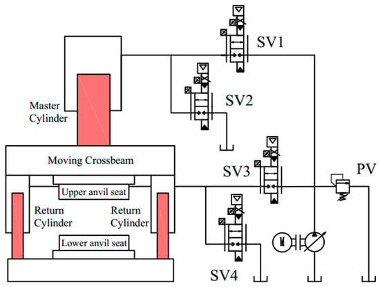
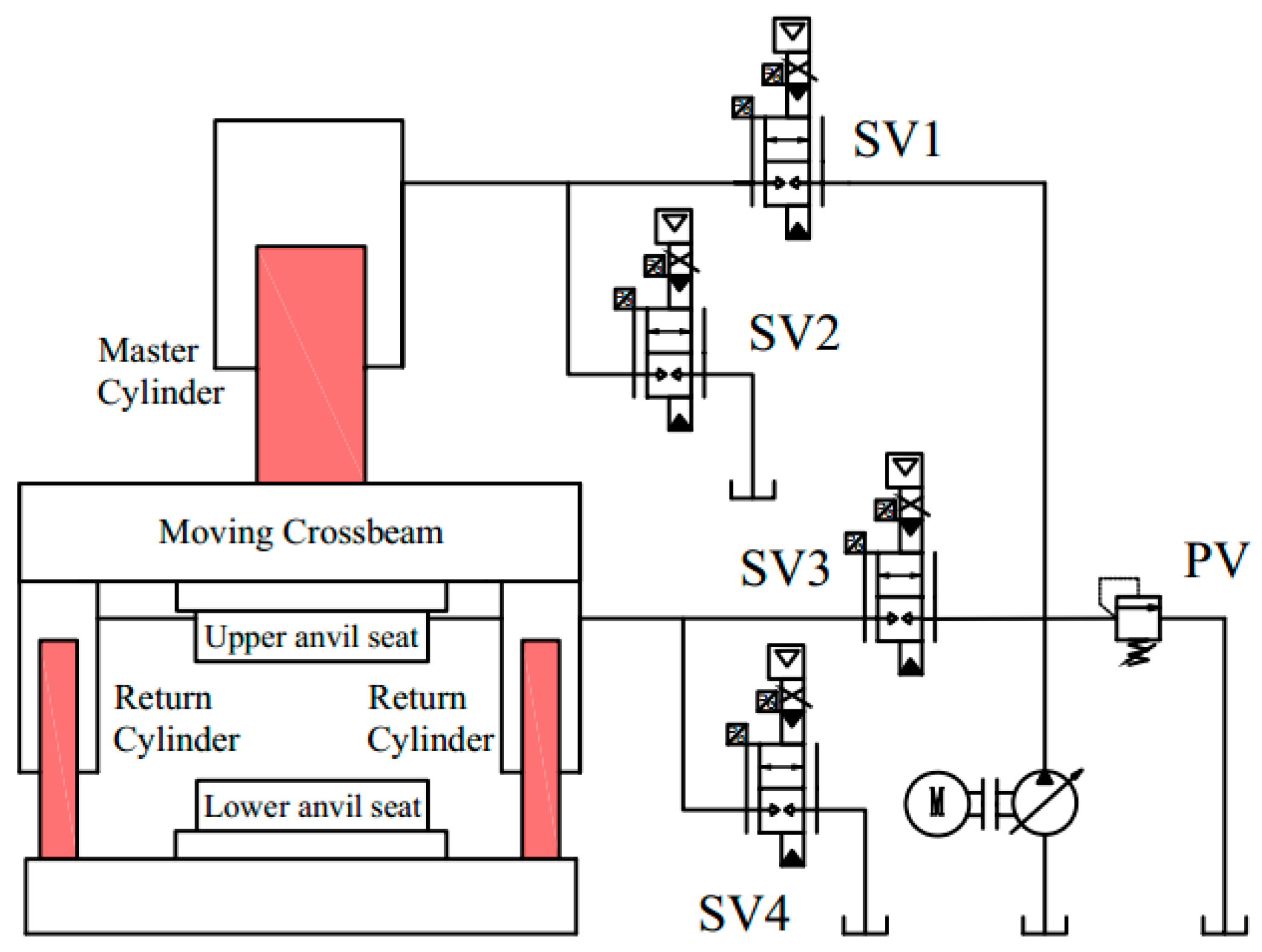
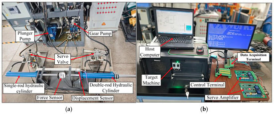
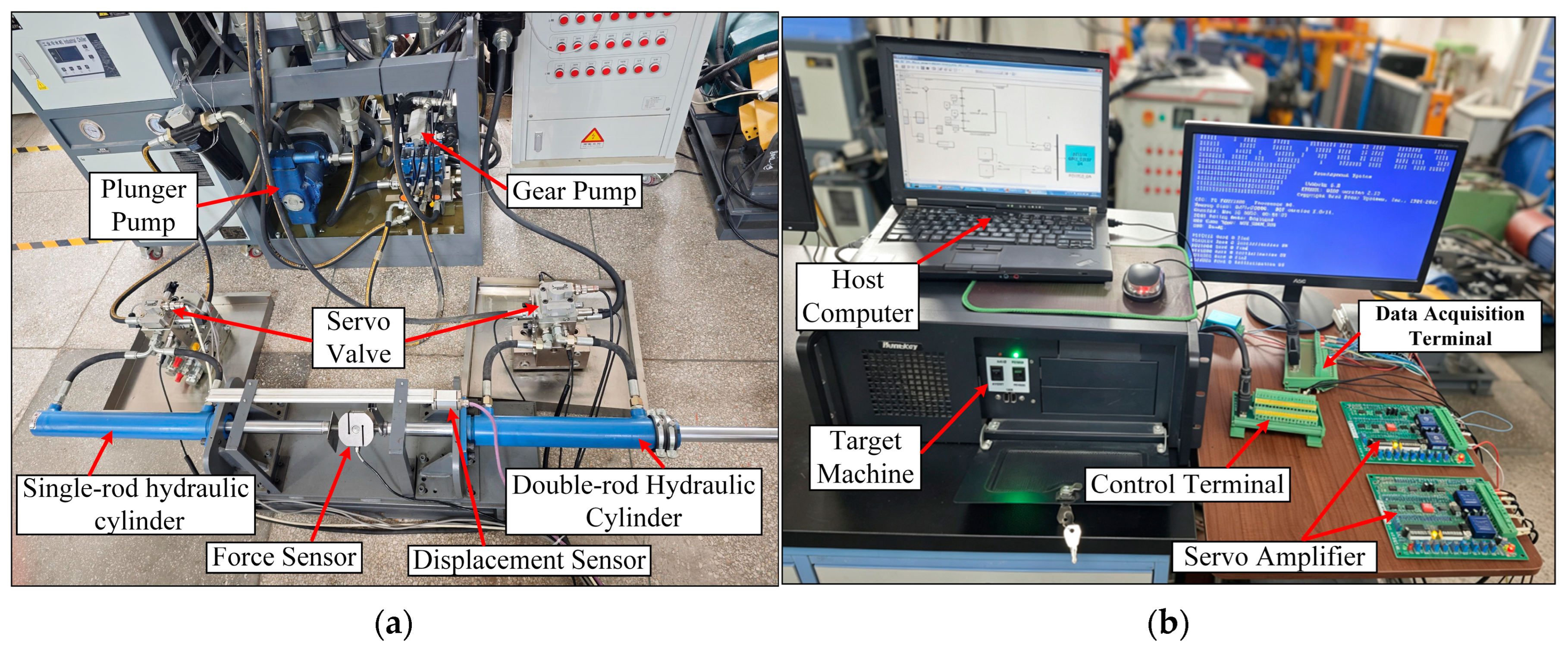
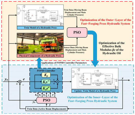
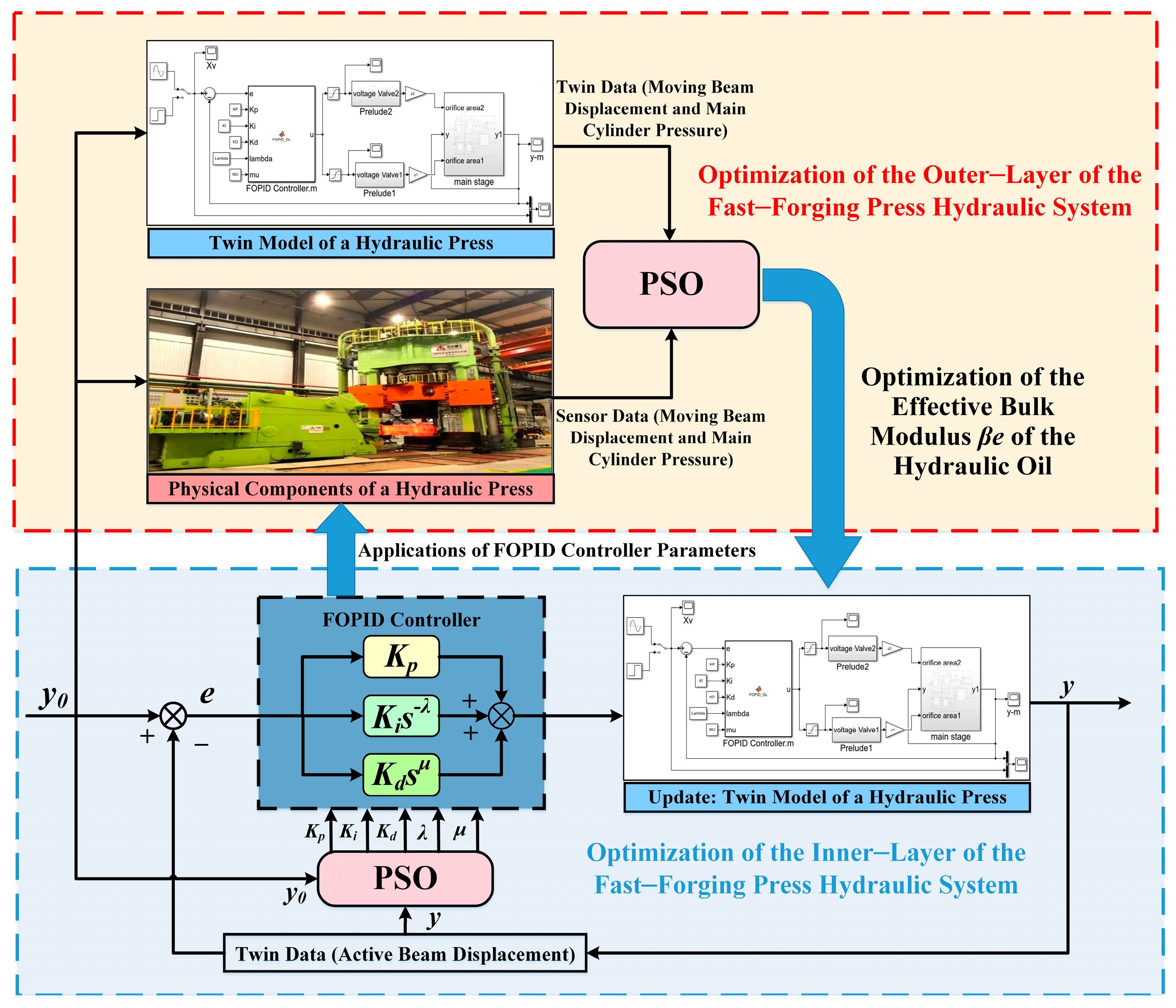
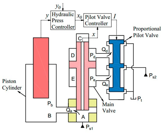
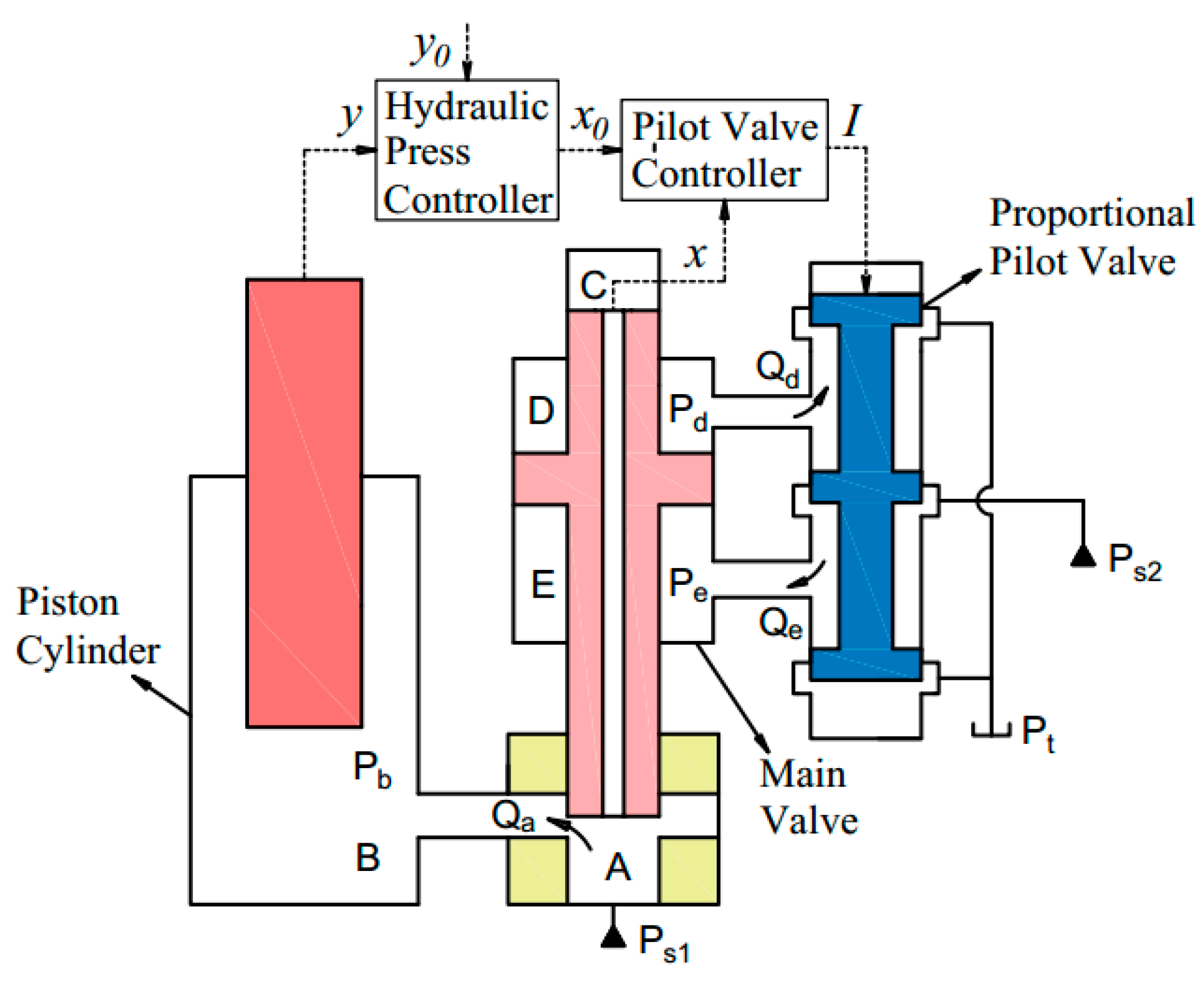
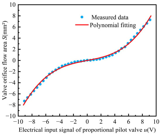
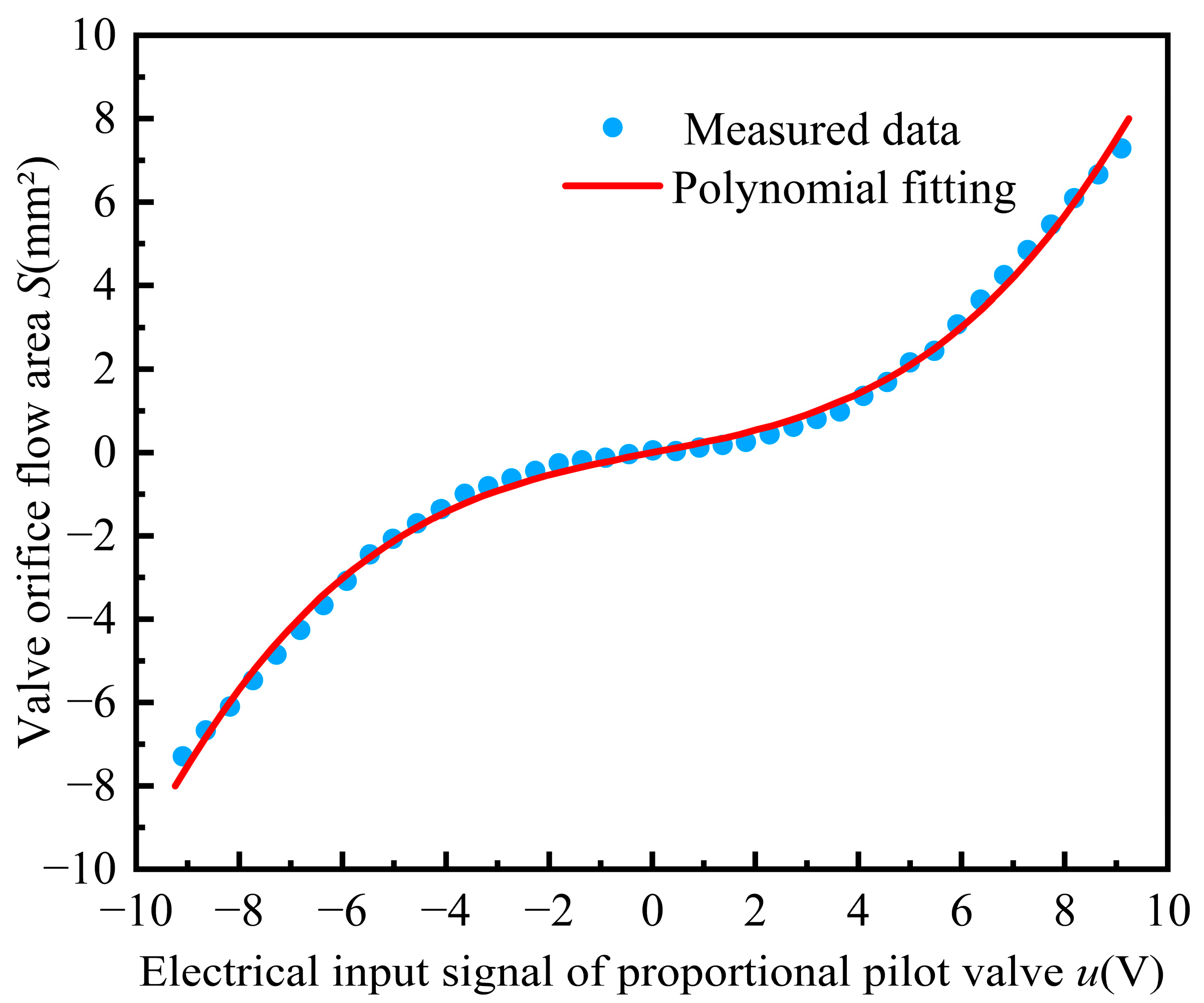
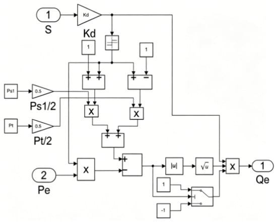
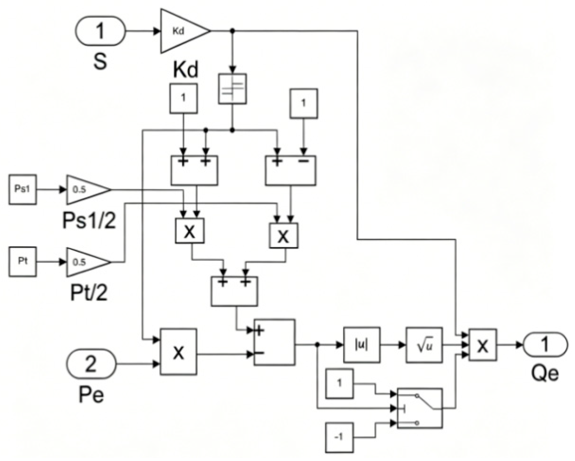
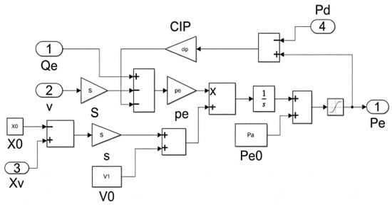
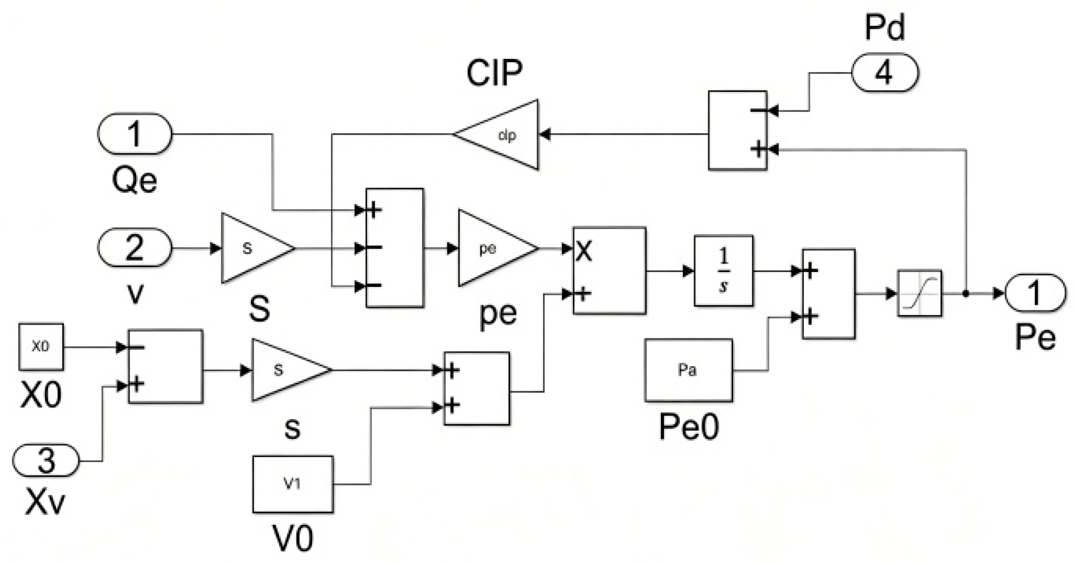
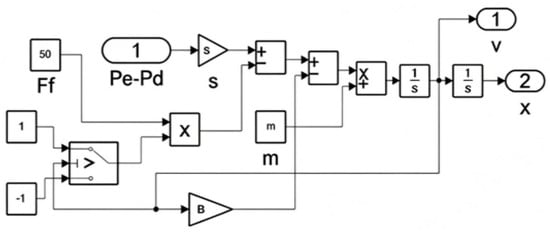
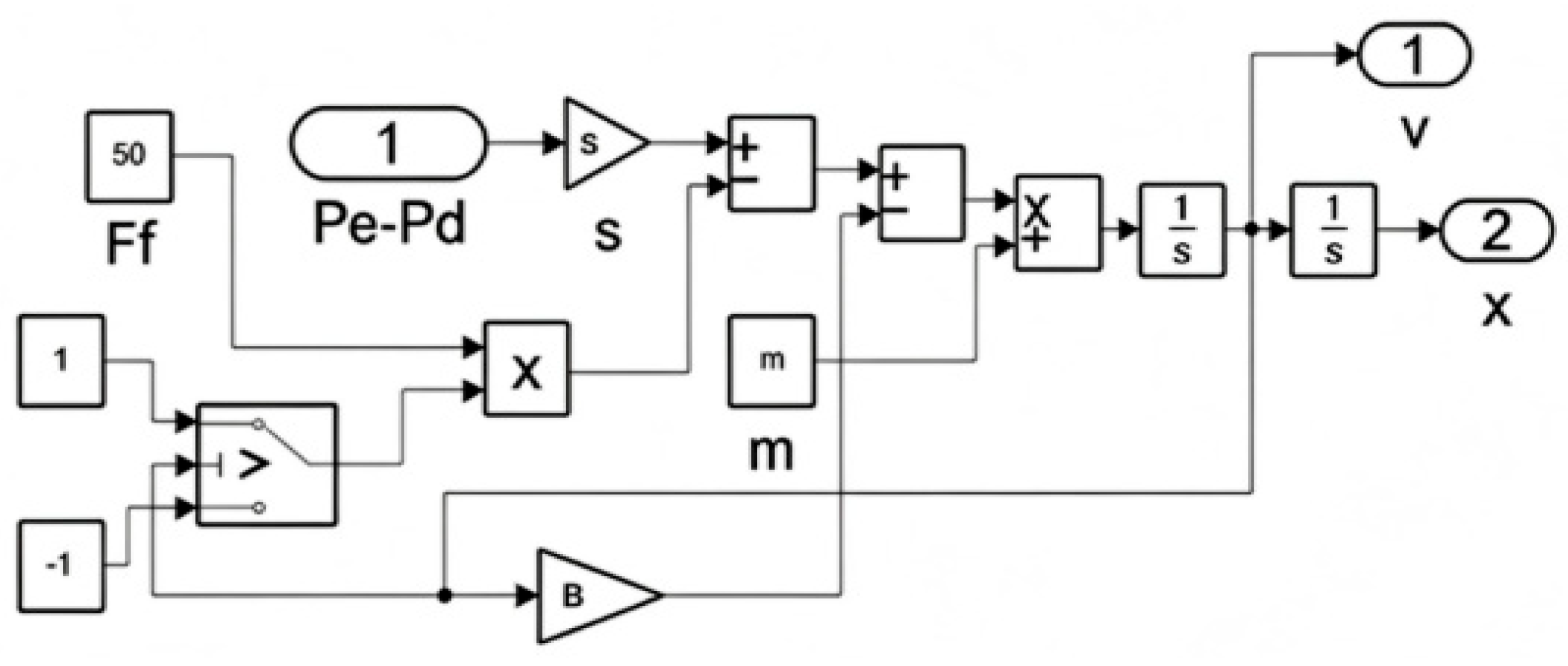
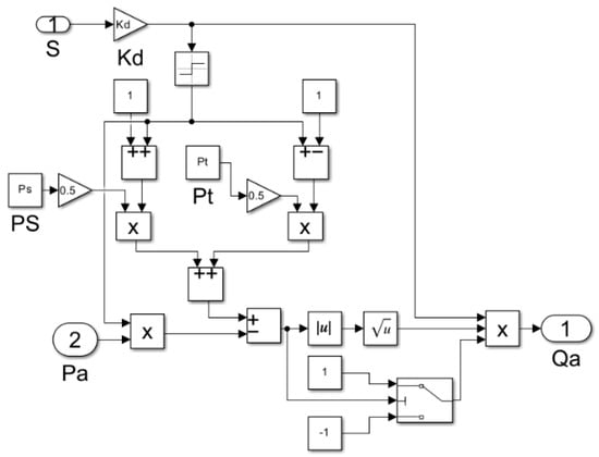
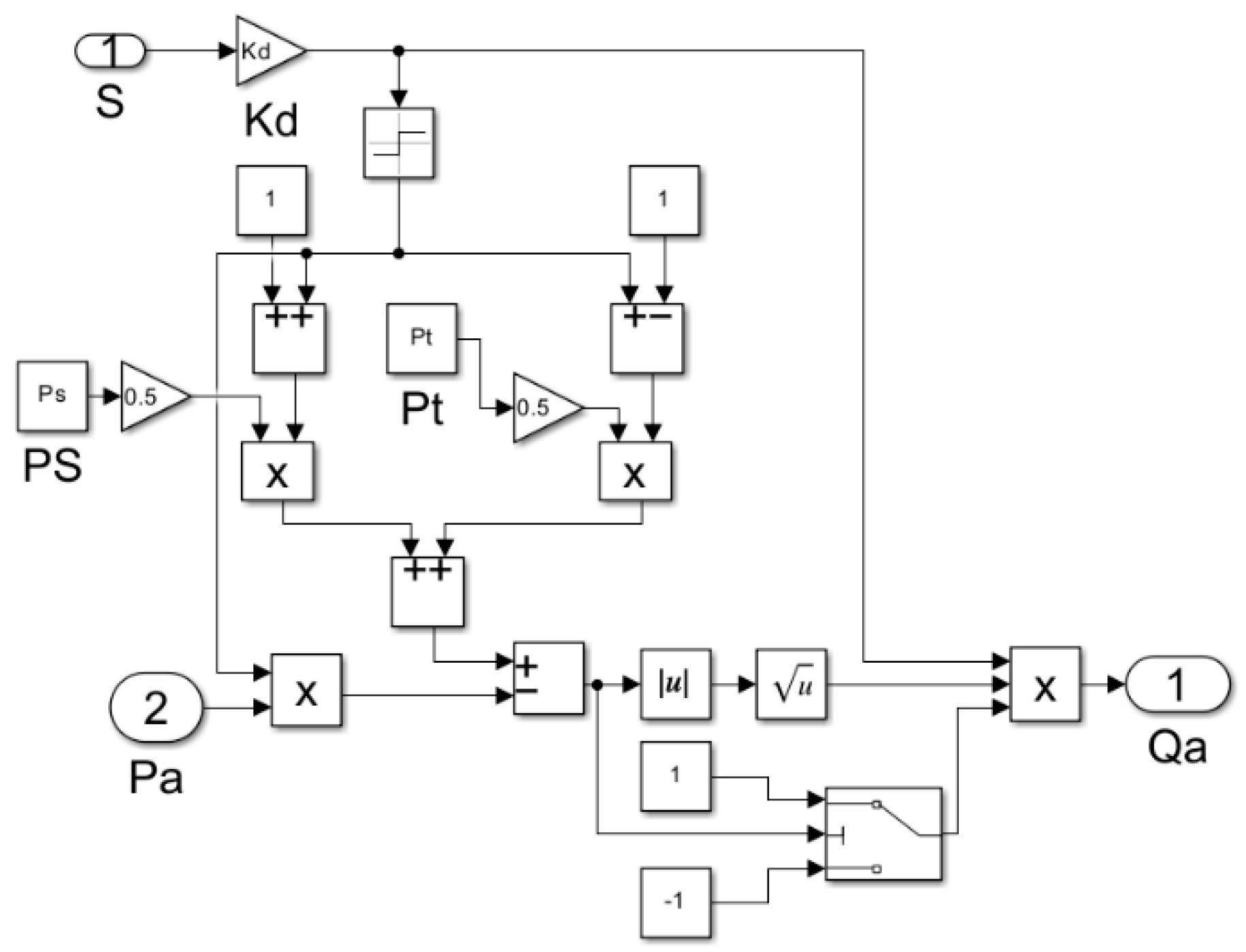
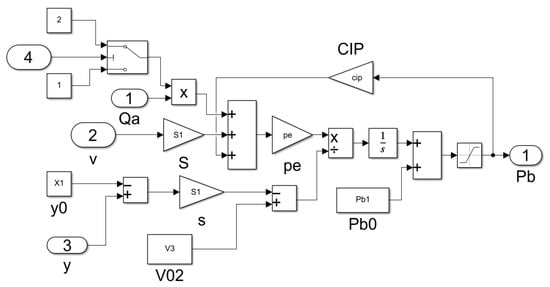
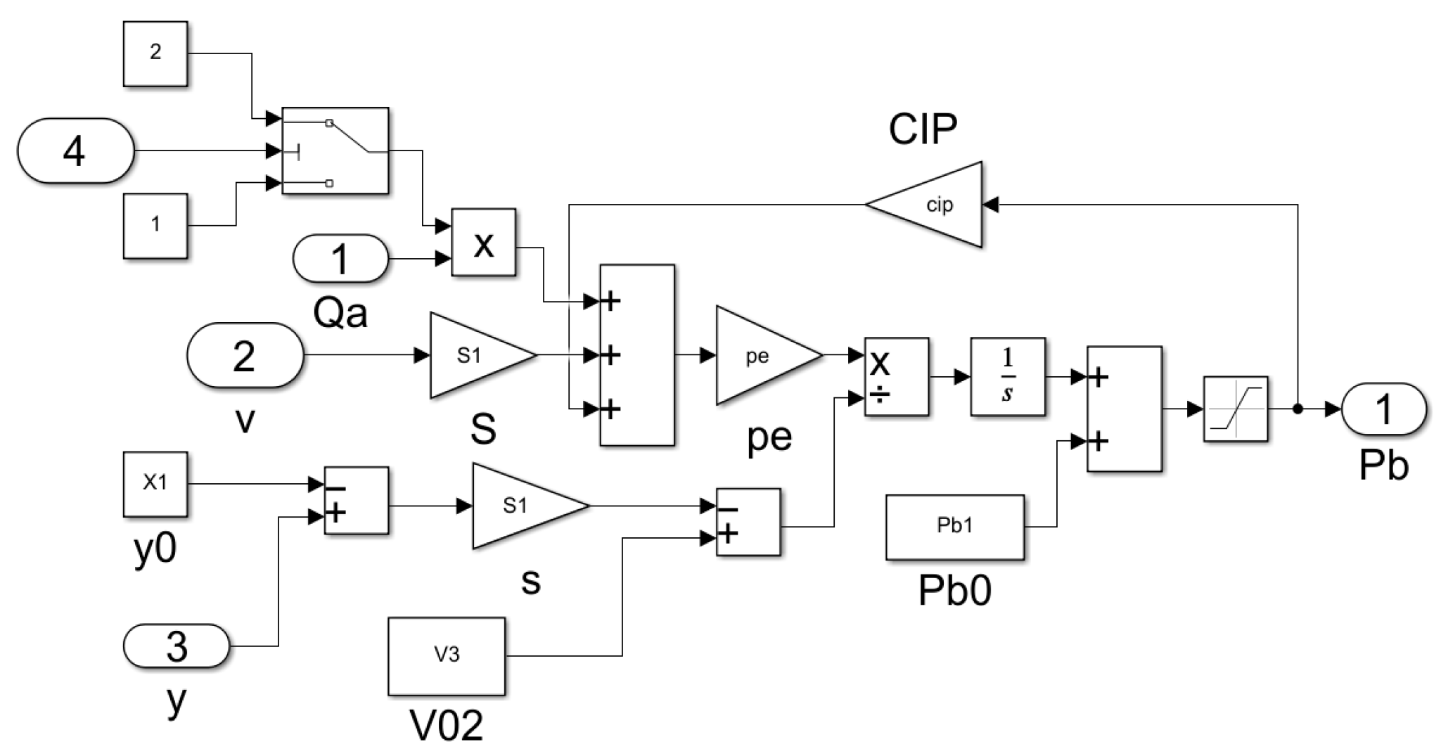
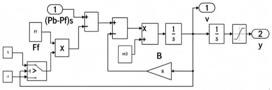
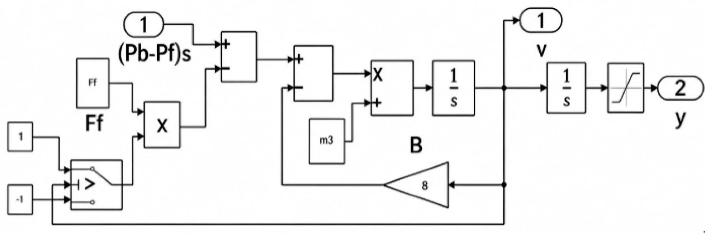
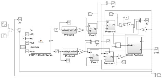
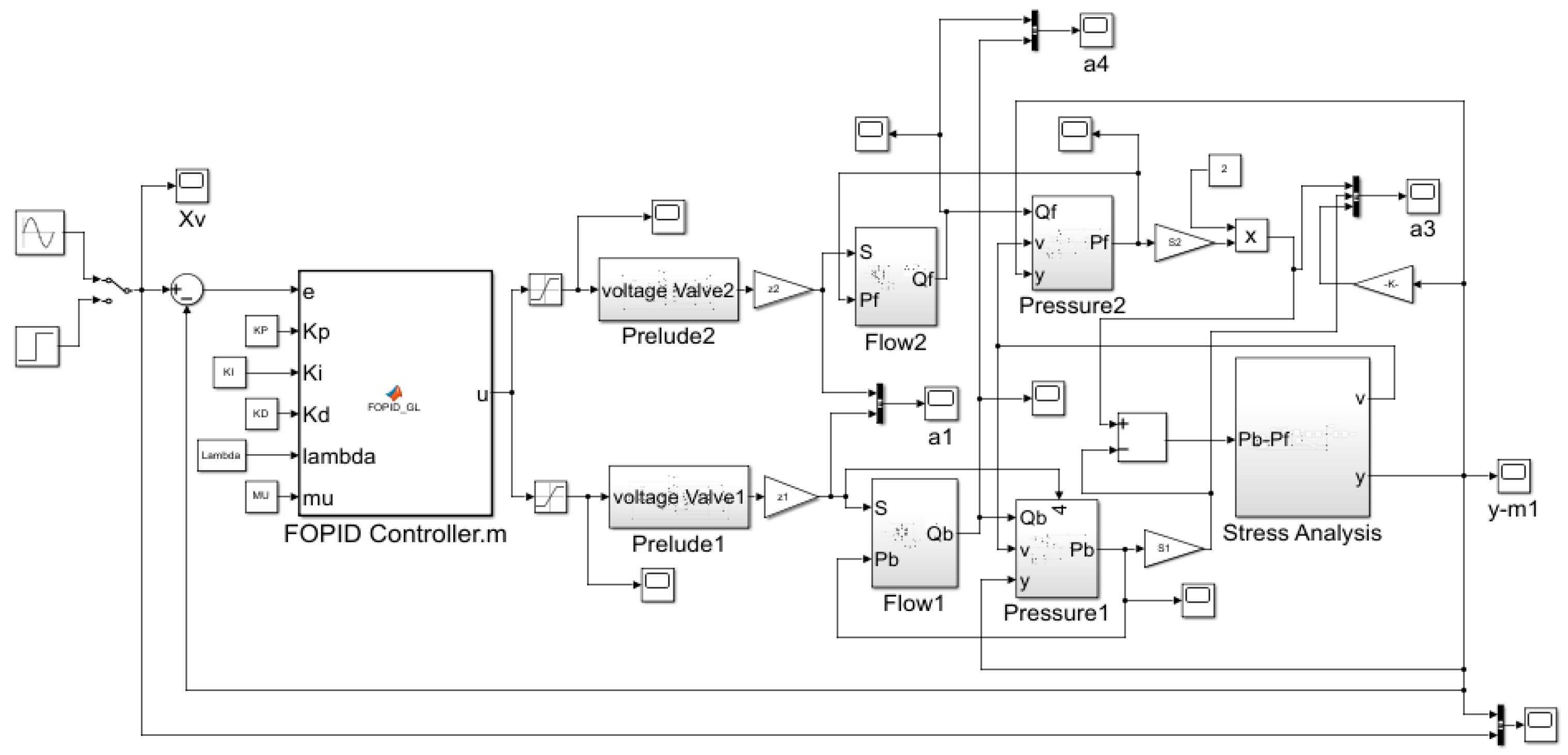
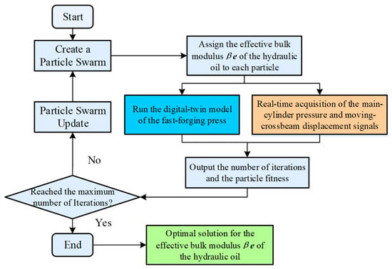
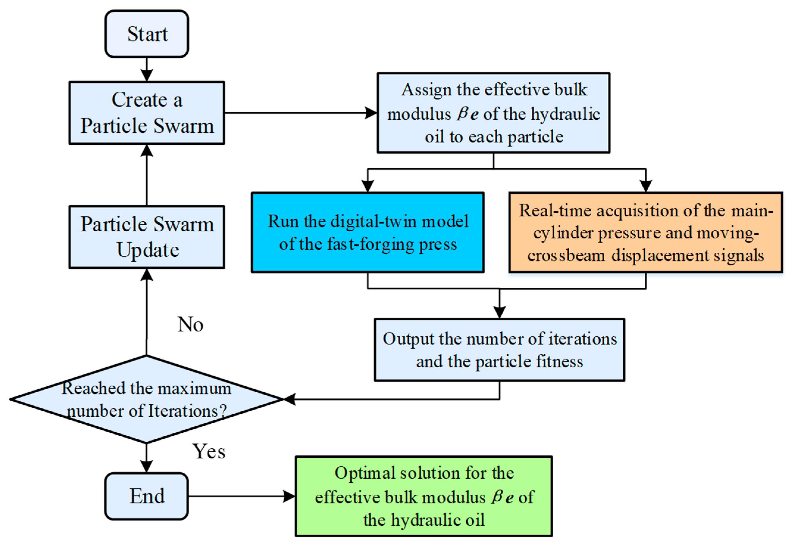
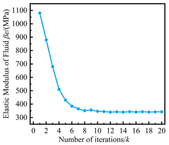
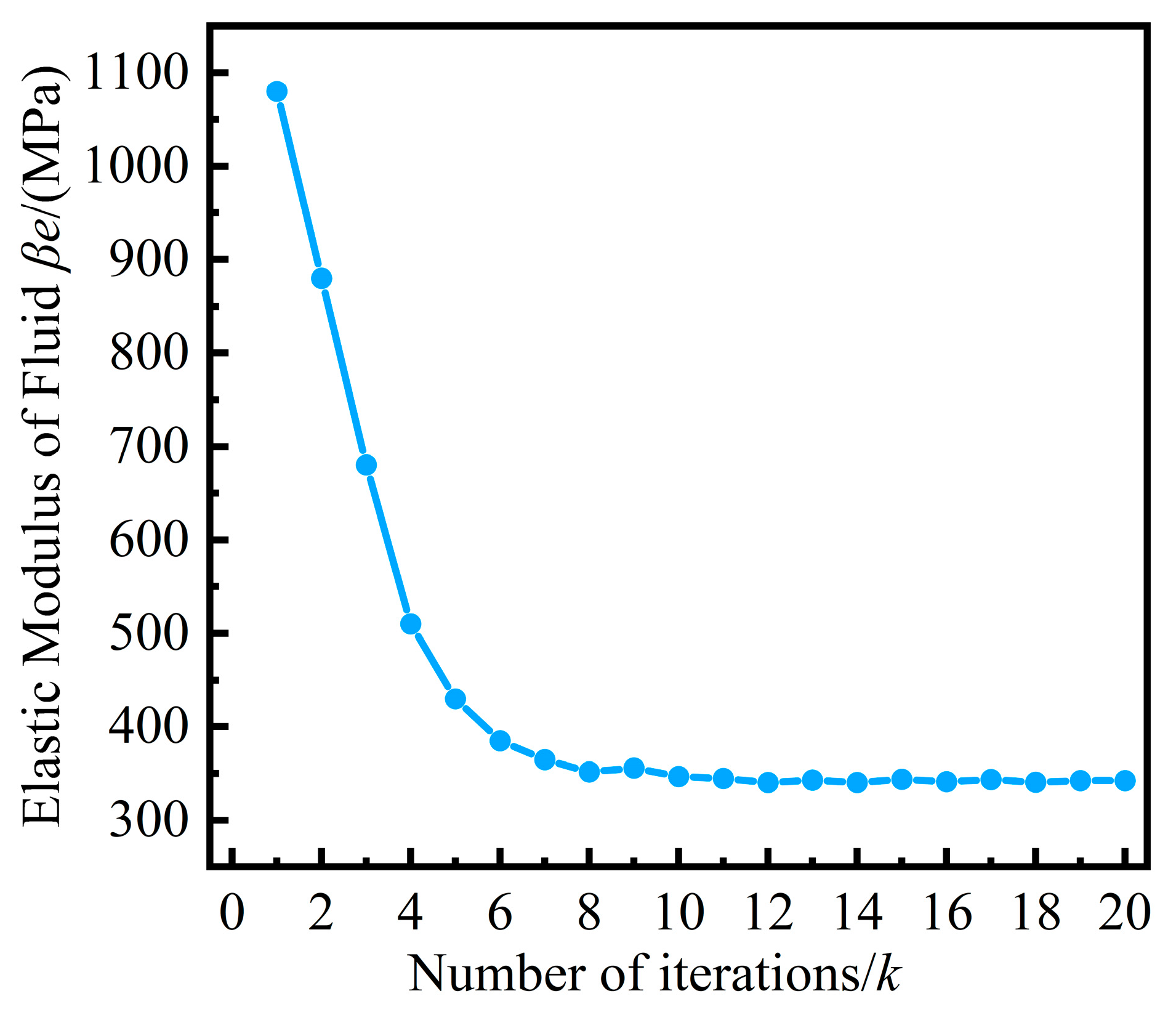
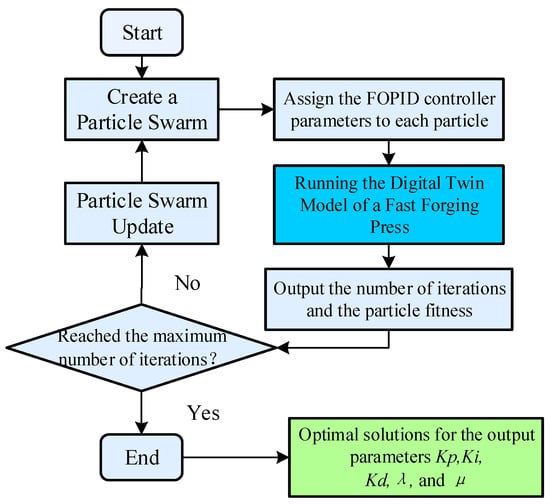
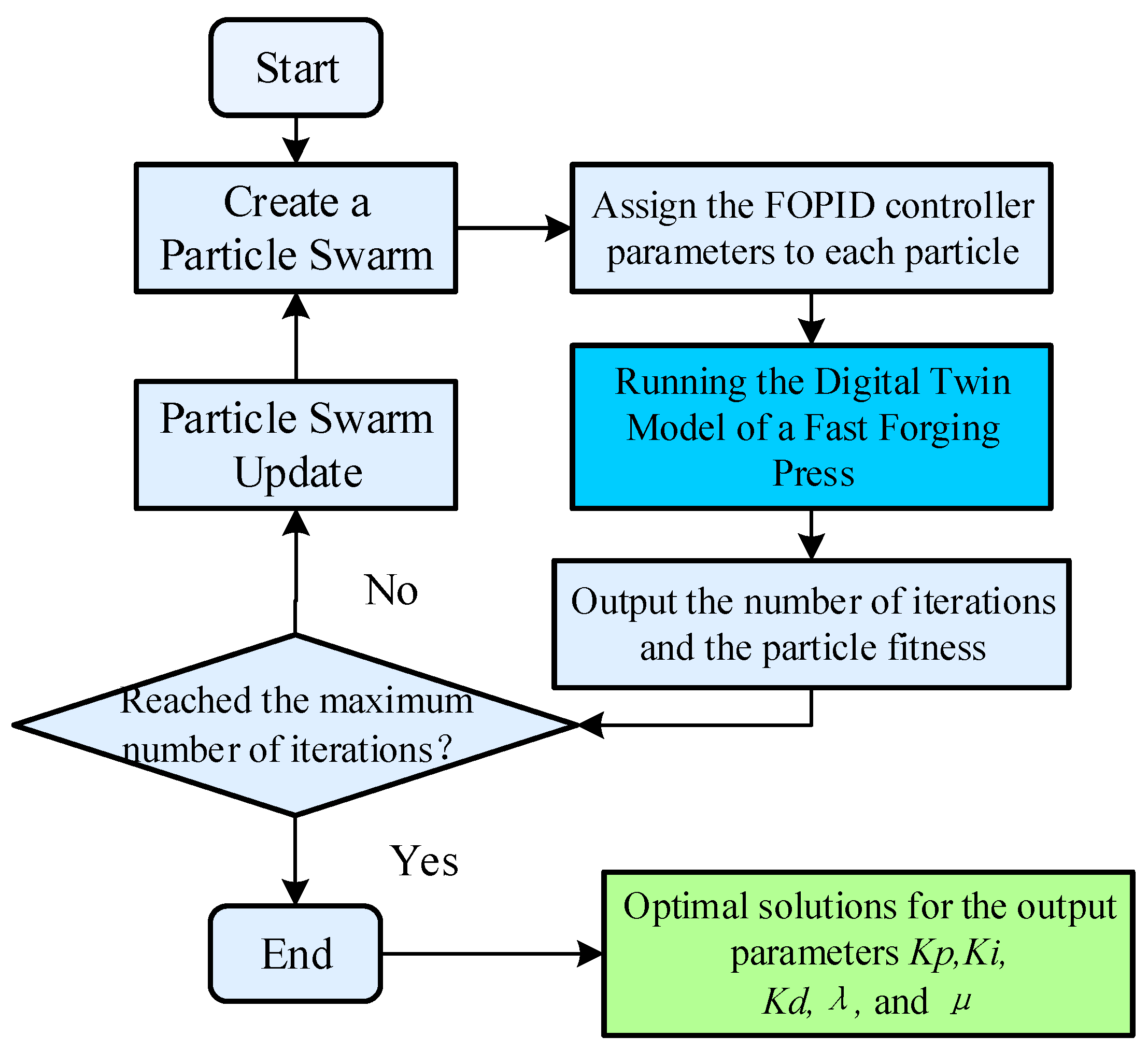
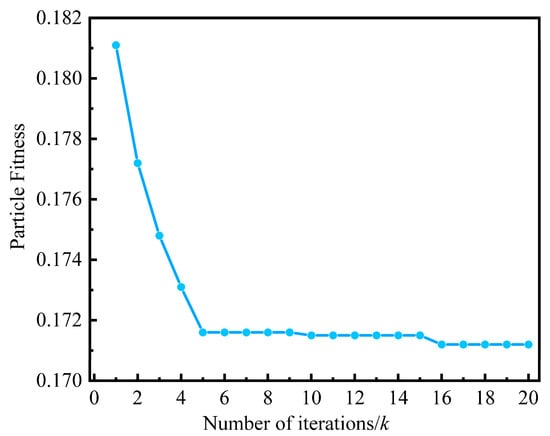
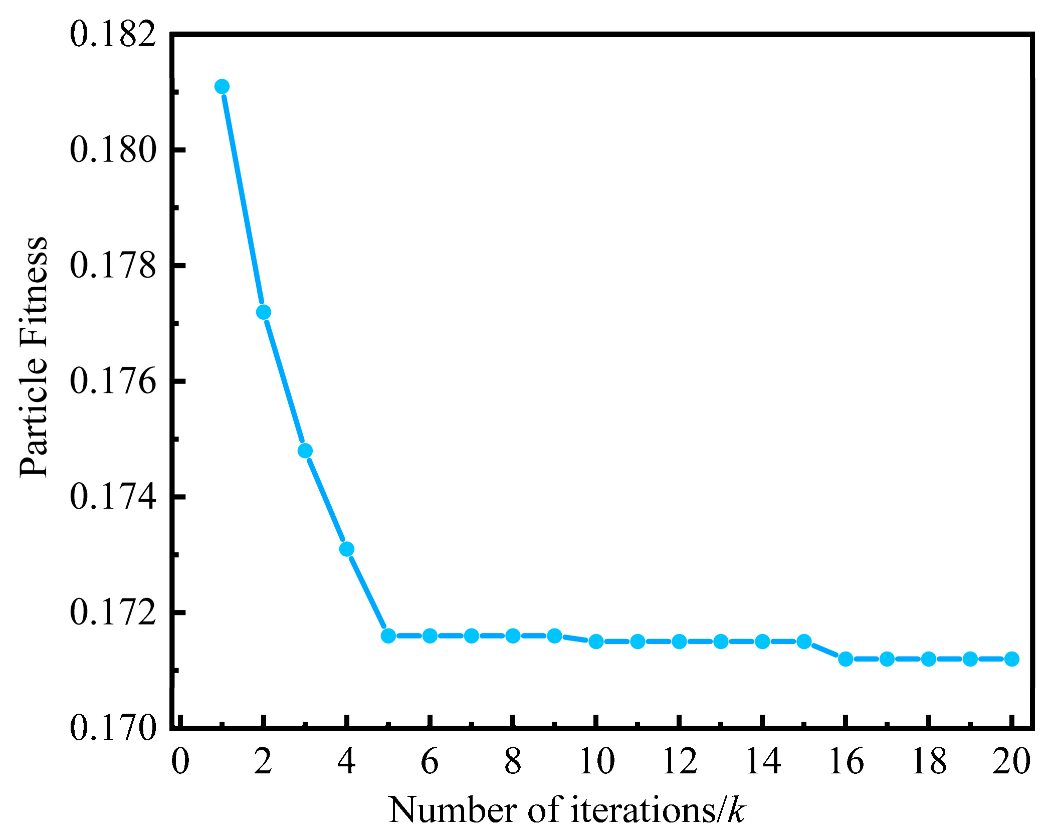
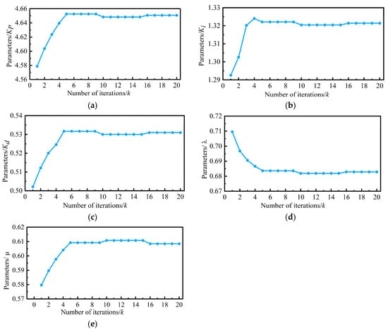
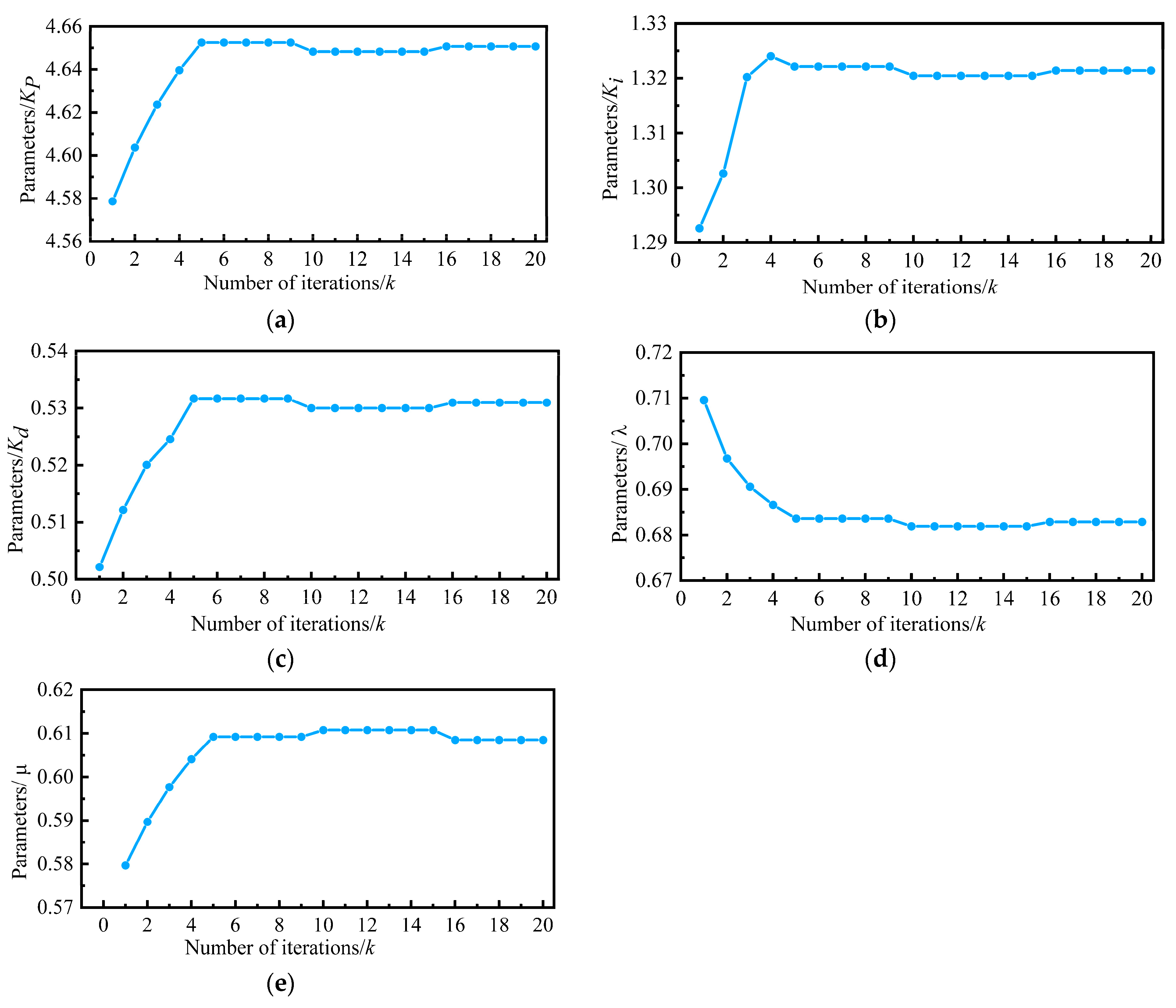
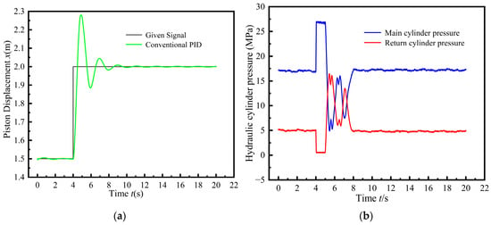
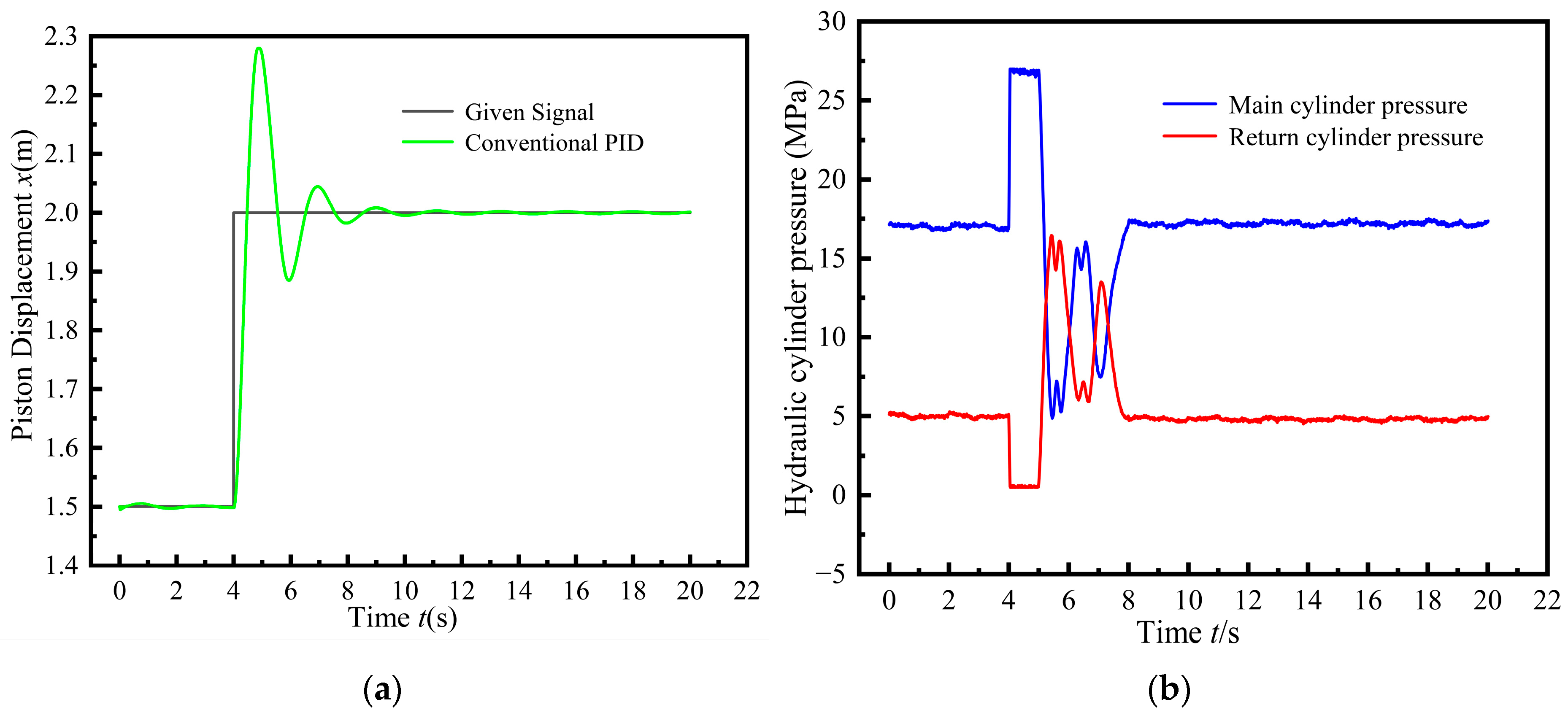
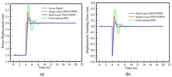
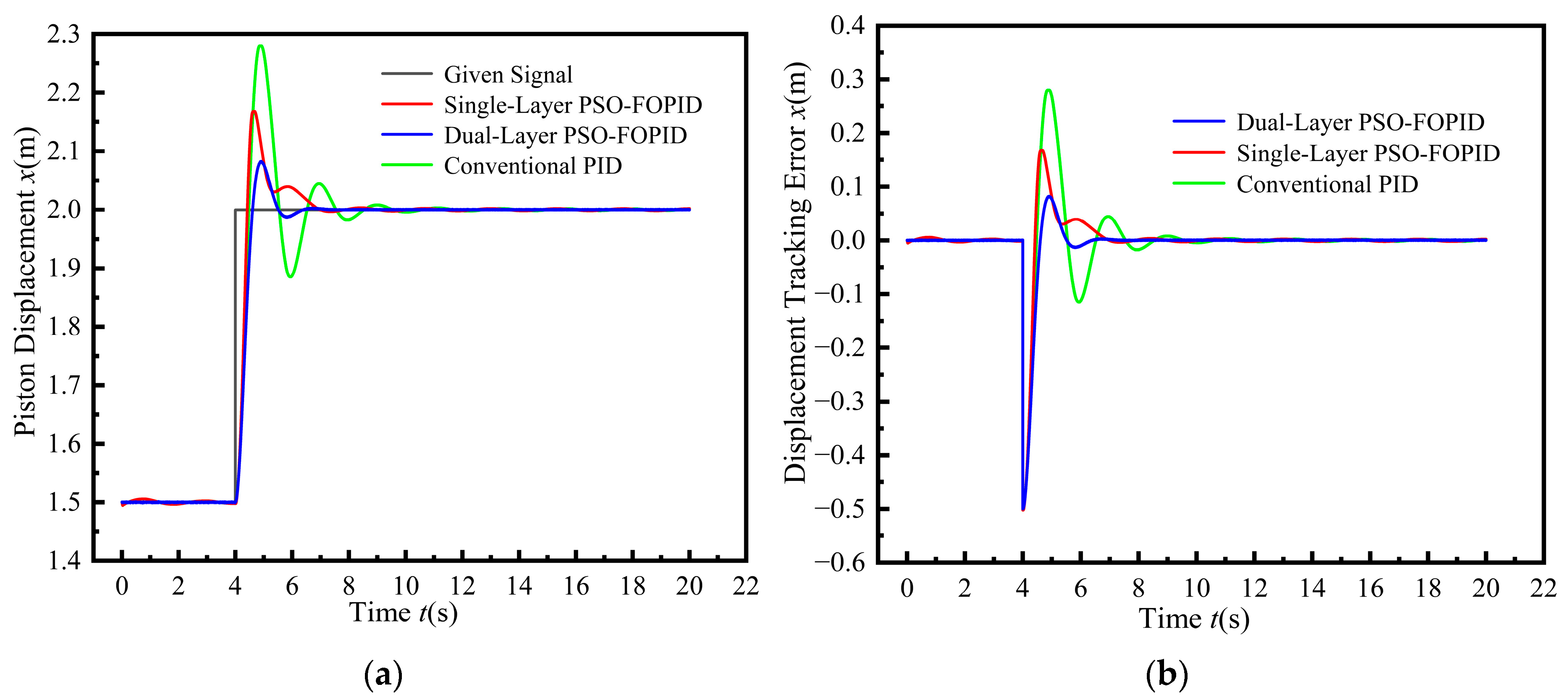
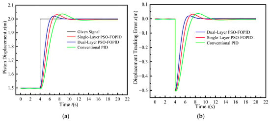
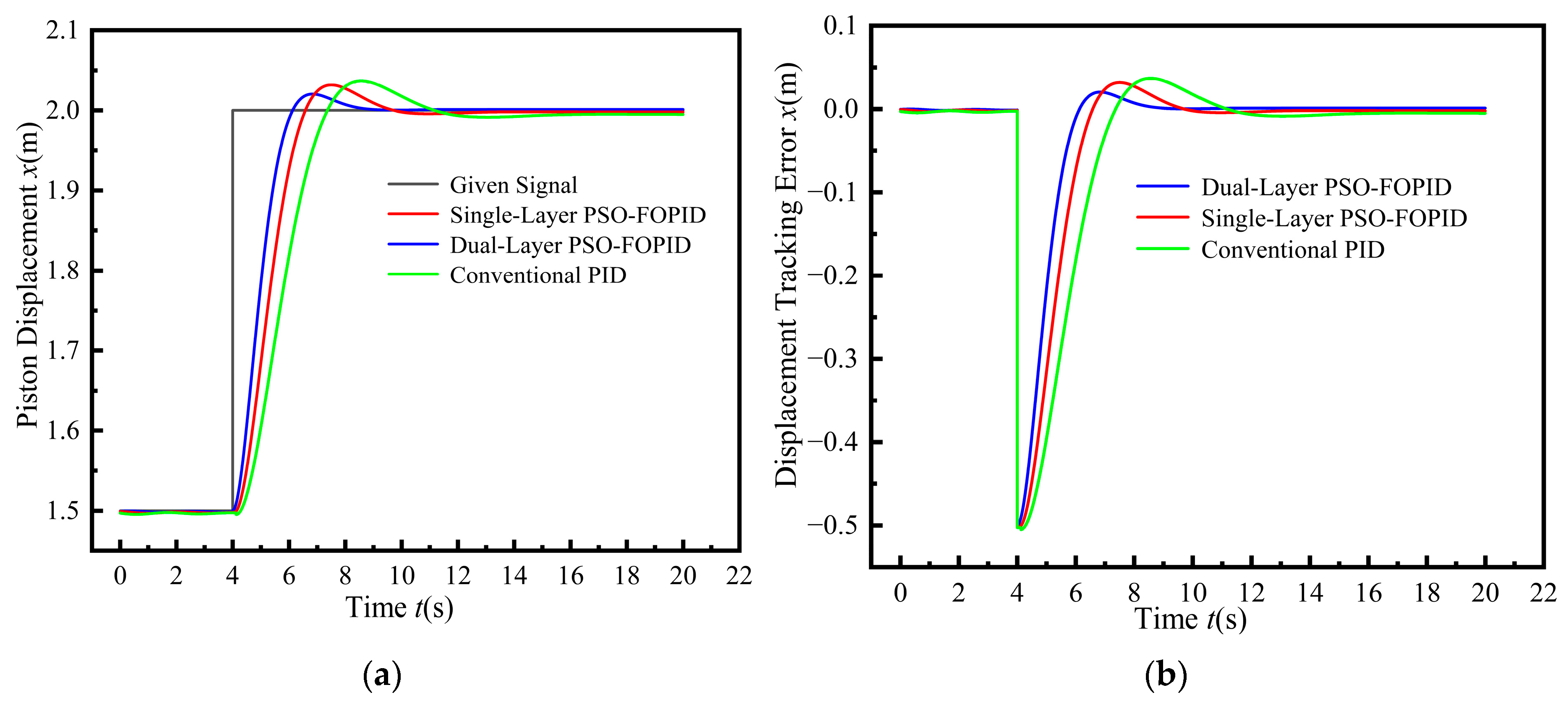
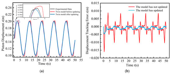
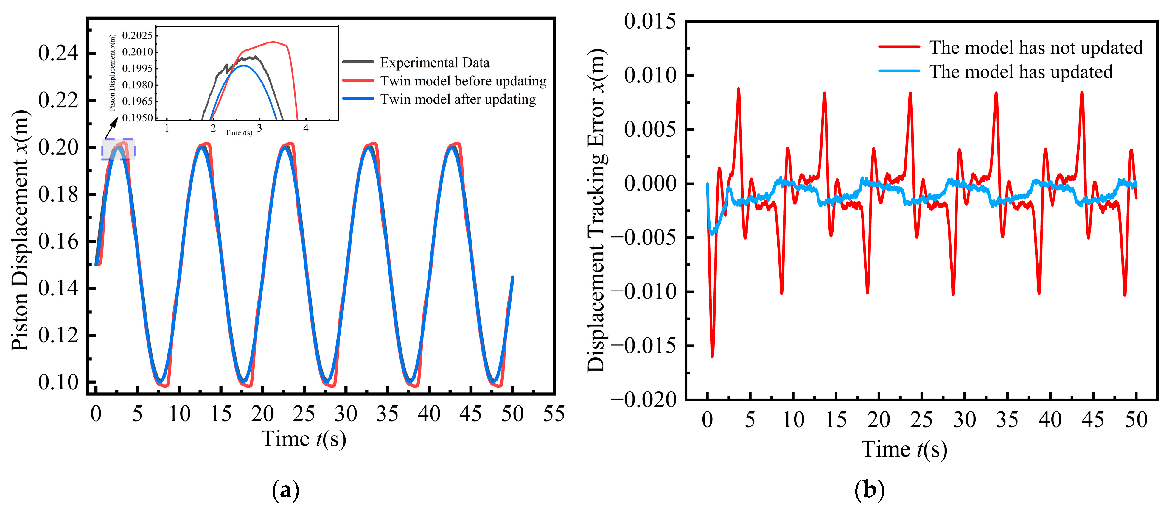
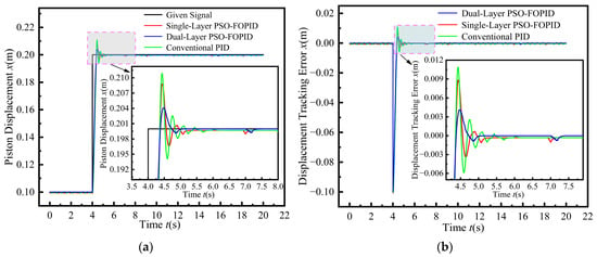
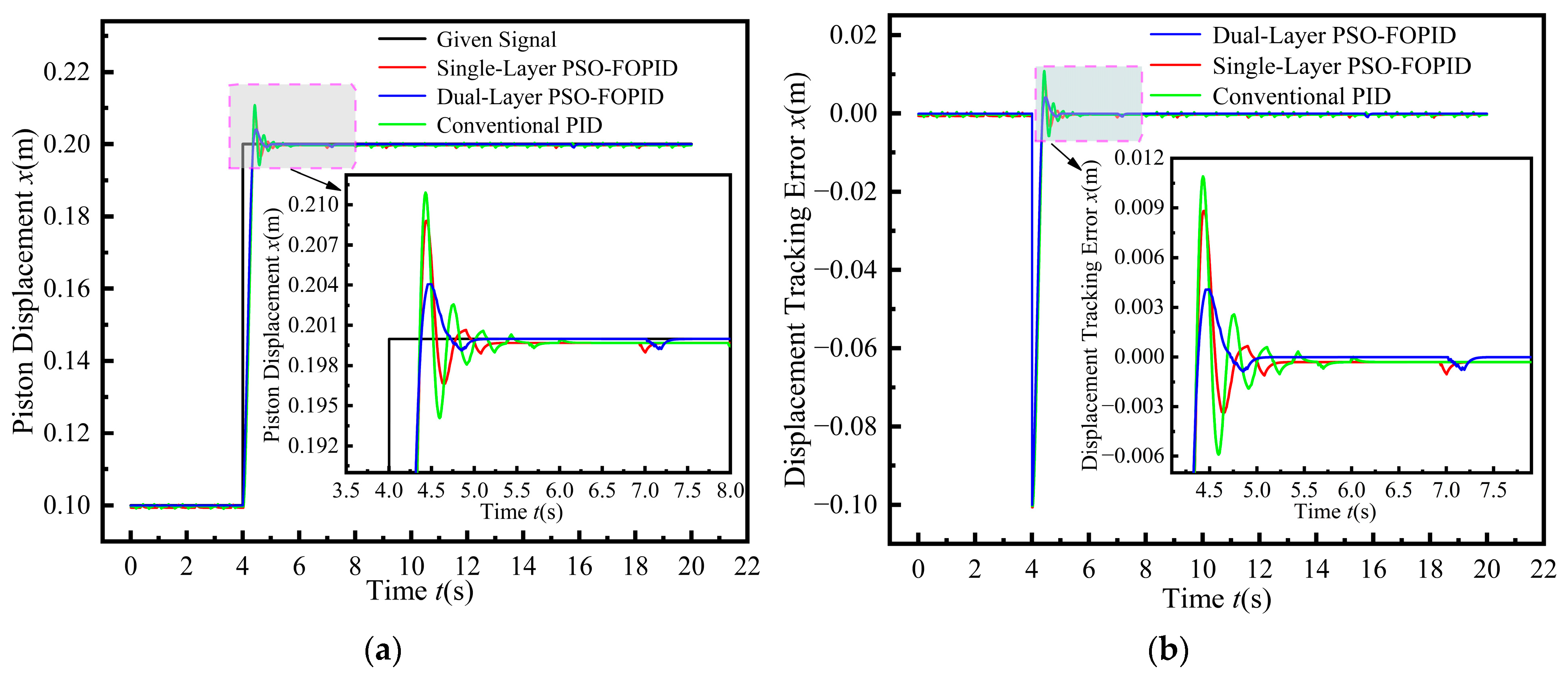
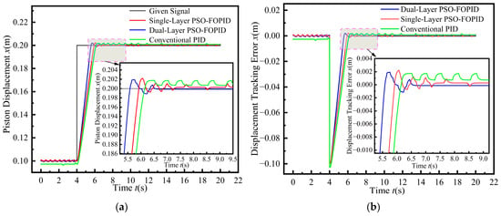
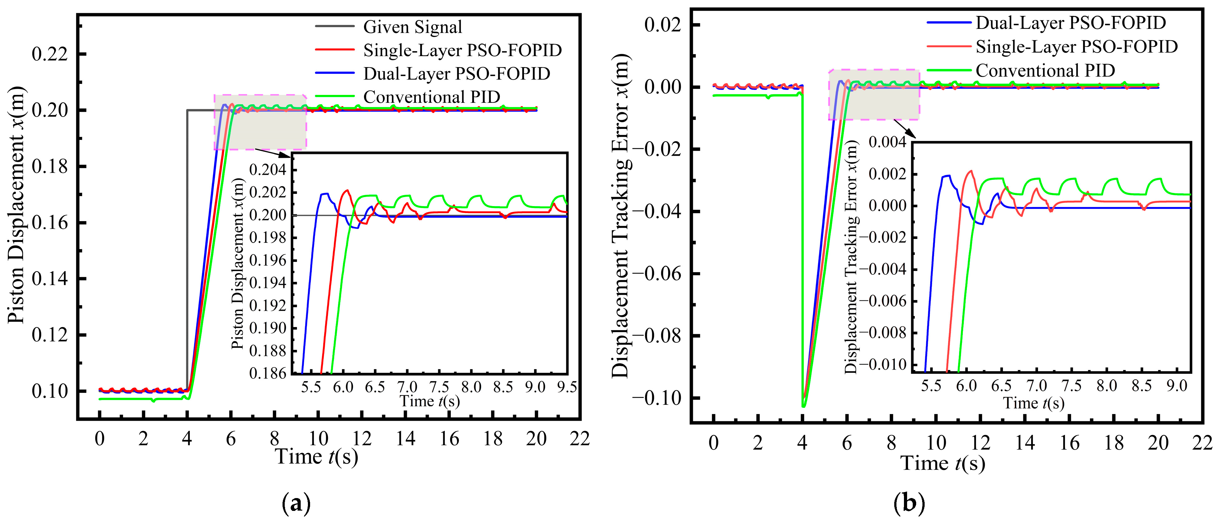

Disclaimer/Publisher’s Note: The statements, opinions and data contained in all publications are solely those of the individual author(s) and contributor(s) and not of MDPI and/or the editor(s). MDPI and/or the editor(s) disclaim responsibility for any injury to people or property resulting from any ideas, methods, instructions or products referred to in the content. |
© 2026 by the authors. Licensee MDPI, Basel, Switzerland. This article is an open access article distributed under the terms and conditions of the Creative Commons Attribution (CC BY) license.