


Abstract
Traditional cascade control structures for surface-mounted permanent magnet synchronous motors (SPMSMs) suffer from strong coupling between the speed and current loops and high sensitivity to parameter variations. To address these issues, this paper proposes a model-free predictive direct speed control (MFPDSC) method based on an ultra-local model. The core innovation lies in constructing a direct speed ultra-local model that mathematically merges the q-axis current dynamics with the motion equation via integration, directly relating the rotor speed to the q-axis voltage. This eliminates the dependence on cascade structures and consolidates the disturbances of both loops into a single lumped perturbation for estimation. Compared with existing model-free predictive direct speed control schemes, the proposed method requires fewer control parameters. The d-axis adopts model-free predictive current control (MFPCC), and disturbances are compensated in real time by a data-driven observer and a reduced-order extended state observer (RESO). The d-axis current control and direct speed control act simultaneously to generate the voltage vector. Finally, experiments on a physical platform demonstrate that the proposed method offers advantages in speed tracking, load disturbance rejection, and robustness against parameter variations, thereby verifying the effectiveness of the proposed control strategy.
1. Introduction
SPMSMs have become core components in electric vehicles, aerospace, and industrial automation owing to their high efficiency, high power density, and wide speed range [1]. As industrial automation continues to advance, motor drive systems are expected to deliver superior transient performance, steady precision, and resilience to parameter variations. The favorable attributes of model predictive control (MPC), namely its rapid transient performance, architectural flexibility, and innate constraint-handling ability, have made it a popular choice in the motor drive community [2]. The conventional model-based predictive control scheme leverages a mathematical model of the motor for state prediction. Despite its simplicity, this approach suffers from notable drawbacks: it is highly vulnerable to parameter variations and unmodeled effects, and model mismatch inevitably leads to steady-state offsets. To address this issue, traditional remedies adopt parameter-identification-based model correction methods to improve the accuracy of the system model [3,4,5,6]. Despite offering partial mitigation of parameter variations and unmodeled dynamics, these methods remain fundamentally anchored in the system’s physical model. Furthermore, they encounter inherent trade-offs between rapidity and stability, which ultimately restrict their achievable compensation capability. Different from conventional MPC, the data-driven paradigm adopted in model-free predictive control dispenses with the physical model entirely, operating only on sampled data. This eliminates the controller’s sensitivity to model accuracy and has thus sparked considerable research interest.
Model-free predictive current control is one of the most widely adopted schemes because it directly manipulates current variations and can achieve high current tracking accuracy. To realize more precise current prediction and disturbance compensation, existing studies mainly construct data-driven models for disturbance observation, such as look-up tables (LUTs), time series models, artificial intelligence algorithms, and ultra-local models [7]. In [8], a look-up table is applied to MPCC, where voltage vectors are selected by approximating previously stored current variation information. However, LUTs suffer from the so-called updating stagnation effect, which can easily lead to increasing prediction errors [9,10]. Time series-based data-driven models describe the motor drive system as discrete-time transfer functions by exploiting the temporal characteristics of sampled input–output data, thereby eliminating the dependence of the prior model on physical parameters [11,12,13]. Nevertheless, such time series models entail a relatively high computational cost. Some researchers have introduced artificial intelligence algorithms such as neural networks into motor control [14,15]; however, these approaches occupy considerable processor resources and require substantial time for machine learning. The ultra-local model, in its first-order framework, treats all terms unrelated to the input and output as lumped disturbances, which are then compensated via algebraic methods or observers to realize model-free predictive control [16]. To meet higher performance requirements, the ultra-local model has been extended to higher-order forms in [17,18], improving prediction accuracy. In [19], the disturbances are categorized into modeled and unmodeled disturbances, and a high-order extended state observer (HESO) is employed to observe and compensate both, aiming to enhance disturbance estimation accuracy. However, this approach suffers from high computational load and difficulty in tuning observer parameters. Therefore, investigating unmodeled disturbance observers that compensate for the unmodeled disturbances is of great significance for improving observation efficiency and accuracy.
Meanwhile, when only current control is considered, MFPCC still follows the conventional cascade control structure. The speed command must pass through the inner current loop before acting on the electromagnetic torque, and the lag of the current loop directly deteriorates the speed dynamic performance [20,21,22]. To overcome the dynamic response limitations caused by the cascade architecture, scholars have designed model-free predictive direct speed control strategies to improve system dynamic performance [23,24]. MFPDSC is mainly improved in two aspects: the control model and the disturbance observation. Reference [25] combines model-free control with explicit model predictive control. By constructing an ultra-local prediction model and a data-driven observer, it proposes a novel explicit model predictive direct speed control strategy, which improves parameter robustness and solves the problem of limited compensation capability for varying disturbances caused by the finite bandwidth of the extended state observer. Reference [26] reconstructs a second-order mathematical model of the motor speed, equivalently treats the speed disturbance as a composite disturbance of the current, and designs a third-order extended state observer (ESO) to observe the lumped disturbance, thereby improving the system’s response speed to load disturbances and enhancing the constraint control on speed. Reference [27] introduces an equivalent speed tracking error variable as a state variable, establishes a reduced-order ultra-local model, and observes disturbances through an improved nonlinear extended state observer, achieving faster and more accurate composite disturbance estimation and thereby enhancing dynamic performance. Reference [28] observes and compensates for disturbances through an extended sliding mode observer (ESMO), solving the performance degradation problem of conventional model predictive speed control under multi-parameter mismatch and external disturbances. The above direct speed predictive control methods have achieved good results in both speed dynamic characteristics and load disturbance rejection capability. Although the aforementioned methods achieve promising results in dynamic behavior and load disturbance rejection capability, they still face problems such as complex model design, high computational cost, and difficulties in determining weighting factors. Aside from model predictive control and model-free methods, other advanced control strategies have also been applied to PMSM drive systems. For instance, a super-twisting extended state observer-based quasi-proportional-resonant controller has been applied to suppress speed fluctuations in PMSM drive systems [29]. Additionally, a composite adaptive super-twisting sliding mode control using a barrier function has been applied to PM motor drives in electric aircraft to improve flight control accuracy under complex environments [30]. Although these methods achieve strong robustness, they often rely on accurate system models or require complex parameter tuning. Since this paper primarily focuses on model-free predictive control, these methods are not discussed in further detail.
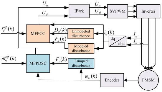
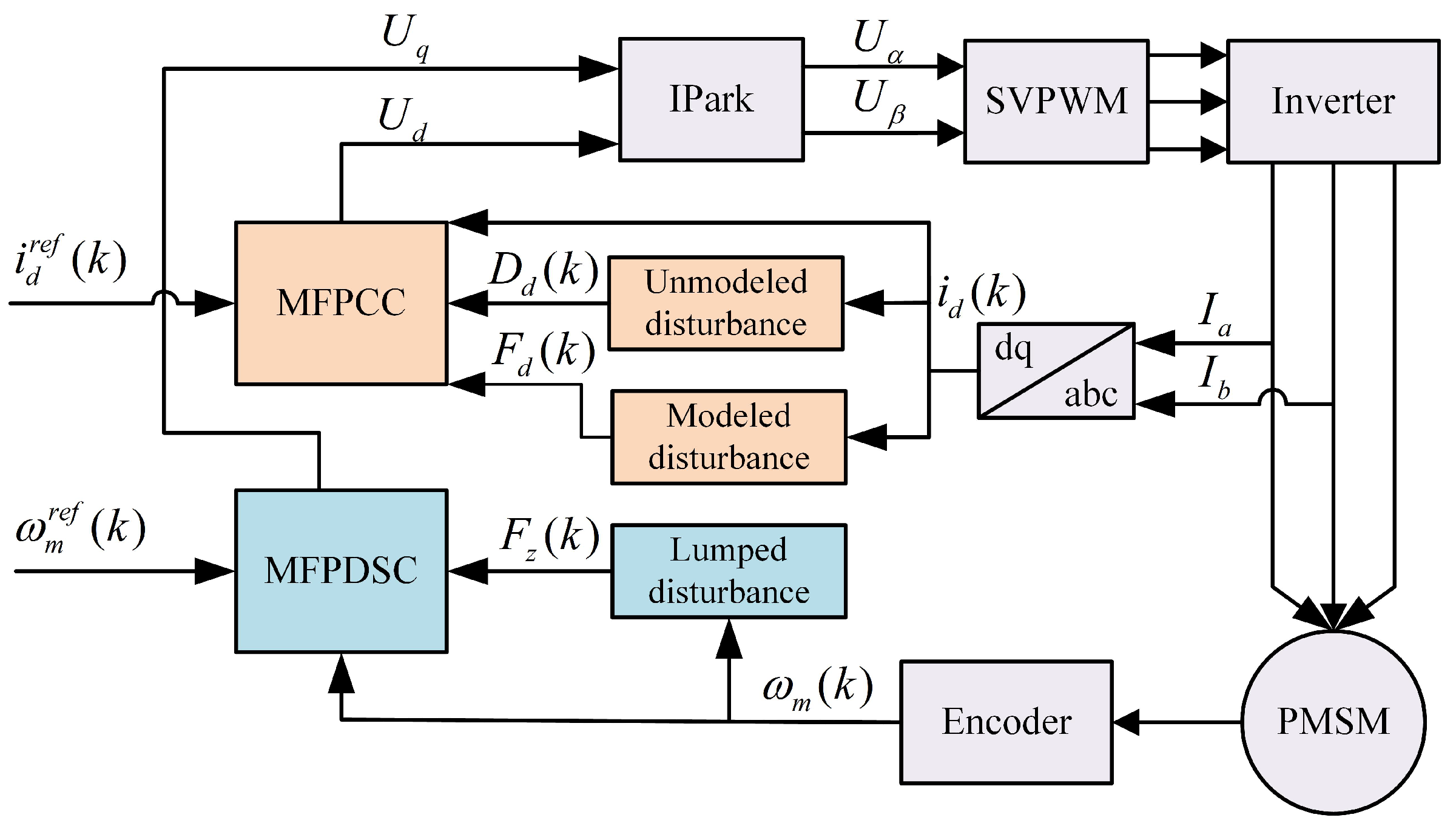
Motivated by the aforementioned concerns, we develop a novel speed control scheme termed MFPDSC, which is grounded in an ultra-local representation. Figure 1 provides a schematic illustration of the proposed framework. The scheme consists of two layers: the first layer is the d-axis current model-free predictive control, and the second layer is the direct speed model-free predictive control. For reconstructing the current behavior on both the d-axes and q-axes, this work employs the ultra-local model within the current-control layer. The modeled disturbances are estimated using the previous state and the unmodeled disturbances are compensated by a RESO, yielding a model-free current control law. In the direct speed control layer, the q-axis current dynamics are mathematically merged with the motion equation, yielding a direct speed ultra-local model that directly relates rotor speed to q-axis voltage. This model consolidates the disturbances originating from both the speed loop and the current loop into a single aggregated perturbation. It is estimated in real time using the previous state, while the d-axis current loop retains the improved disturbance observation structure. The proposed method directly applies the speed command to the electromagnetic torque, eliminating the lag inherent in the cascade control structure and thereby enhancing the system’s dynamic response speed and robustness. The proposed method is tested on a SPMSM drive platform through comparative experiments against classical PI control and MFPCC. These results clearly attest to the superiority of our control strategy.
Figure 1.
Block diagram of the model-free predictive direct speed control.
The remainder of this paper is organized as follows. Section 2 introduces the MFPCC, including the construction of the current ultra-local model and the design of the RESO. Section 3 presents the proposed MFPDSC, detailing the derivation of the direct speed ultra-local model, the control law, and the lumped disturbance observer. Section 4 provides the system stability proof for both the d-/q-axis current closed-loop and the direct speed closed-loop using root-locus analysis. Section 5 describes the experimental setup and comparative results against PI control and MFPCC under speed tracking, load disturbance, and parameter sensitivity tests. Finally, Section 6 concludes the paper.
2. Model-Free Predictive Current Control
To overcome the limitations of predictive current control in terms of disturbance observation accuracy and computational burden, this work employs an ultra-local model for reconstructing the current dynamics. A model-free predictive current control law is subsequently developed. In this framework, disturbances are handled separately: the modeled part is derived from prior-step input and output data, while the unmodeled part is compensated through a RESO.
2.1. Construction of Current Ultra-Local Model
For a SPMSM operated in the synchronous rotating frame, the stator current dynamics are governed by the following equation:
In the above equations, and denote the d-/q-axis voltages, currents, and inductances, respectively. For the SPMSM considered herein, , with representing the stator resistance and being the permanent-magnet flux linkage. The electrical angular speed is given by , where is the pole-pair count.
Applying the ultra-local modeling methodology establishes a direct mapping from the input variables to the perturbation terms in the motor current equations. This reconstructed model is summarized by the following expression:
where and are the proportional gains of the input variables, with . and are the modeled lumped disturbances, which include the effects of the input variables, and their specific expressions are given by the following:
The aforementioned reconstructed model only reflects the electromagnetic relationship based on ideal parameters and known dynamics, without considering the unmodeled dynamics present in practical operation. Affected by factors such as inverter nonlinearity and parameter perturbations, deviations arise between the actual current response and the ideal model, leading to degraded prediction accuracy. Therefore, an unmodeled disturbance term must be incorporated into the current equations to enable online observation and mitigation of the system uncertainties. This will enhance the model’s ability to capture the true plant dynamics, while also boosting the tracking accuracy and disturbance rejection of the control system. The extended ultra-local model incorporating the unmodeled disturbance is given by the following:
where and represent the unmodeled disturbances, which need to be compensated online by an observer.
2.2. Design of Model-Free Predictive Current Control Law
Forward Euler discretization of (4) yields the prediction equations for the d-/q-axis currents as follows:
where is the current sampling period, and denotes the estimated value of the modeled disturbance at the k-th instant.
In practical digital control systems, phase lag occurs due to factors such as computation, sampling hold, and execution delays, which in turn degrade the dynamic response and tracking accuracy. We incorporate a one-step delay compensation to counteract the negative impacts of sampling/processing delays. The resulting current prediction equations, including this compensation, take the following form:
The continuous-control-set model-free predictive control method is employed in this work, which requires the d-/q-axis voltage commands to be determined from (6). By extracting the voltage-related terms, we obtain the following:
By setting the predicted currents at instant equal to their references, i.e., and , and inserting these equalities into (7), we derive the model-free predictive current control law as follows:
where denotes the d-axis reference current, while , coming from the speed-loop output, is the q-axisreference current.
2.3. Design of Disturbance Observer
Given the distinct nature of these disturbance components, we adopt separate estimation schemes for the modeled and unmodeled parts. The modeled disturbances and capture the deterministic portion of the system behavior, including ohmic losses in the stator windings and the back electromotive force induced by rotor motion. Together, they dominate the overall current dynamics. The unmodeled disturbances and mainly originate from high-order harmonics caused by inverter nonlinearity and rotor vibrations, and their amplitudes are typically much smaller than those of the fundamental components; moreover, the high-frequency components can be filtered by the motor inductance. Therefore, the influence of the unmodeled disturbances on the modeled disturbances can be neglected when observing the modeled disturbances.
2.3.1. Estimation of Modeled Disturbances
From (3), it is known that the modeled disturbances are determined by the currents and the electrical speed. Given the high sampling rate of the current loop, the electrical time constant far exceeds the sampling period. Consequently, variations in , and from one sampling instant to the next are safely disregarded. Taking the derivative of and yields the following:
Within the rated operating range of the motor, all terms in the expressions are bounded; therefore, and are bounded. According to the mean value theorem, during the sampling period , the variations of and satisfy and , where M is a constant. When is sufficiently small, and can be neglected, yielding , .
Using the discrete equation at instant k in (5) and its counterpart at instant , we obtain the estimated modeled disturbances as follows:
2.3.2. Estimation of Unmodeled Disturbances
For the unmodeled component, a conventional solution relies on a HESO that estimates both modeled and unmodeled disturbances simultaneously. This approach, however, complicates the tuning of observer gains. Our paper instead utilizes a RESO to perform the observation, which effectively applies compensation on top of the already estimated modeled disturbances. Using the d-axis extended ultra-local model for illustration, we formulate the observer as follows:
where and are the gain parameters of the observer.
Under zero initial conditions, applying the Laplace transform to (11) yields the following:
where is the actual unmodeled disturbance . Substituting it into (12) yields the transfer function as follows:
From (13), it can be seen that the observer’s ability to observe the unmodeled disturbances is determined by the frequency characteristics of its transfer function. Given that unmodeled dynamics are mostly low-frequency in nature, the observer design can be reduced to that of a second-order low-pass filter, i.e.,
Comparing (13) with (14), the relationship between the observer gain parameters and the bandwidth can be obtained as follows:
For observer stability, the pole-placement condition requires both poles to reside in the left half-plane, i.e., and , which implies . The bandwidth governs the trade-off between the observer’s tracking agility and its noise rejection capability. A larger enables quicker dynamic response, accompanied by the risk of high-frequency noise amplification; therefore, it should be selected reasonably according to the actual system bandwidth.
Forward Euler discretization of the continuous-domain observer yields the following discrete-time observer equation:
Since the current model of a SPMSM features a completely symmetrical structure, the d-axis observer and the q-axis observer share the same form, and their dynamic characteristics are solely determined by the bandwidth. Therefore, the observer bandwidths for both axes are set to , and the discrete-time q-axis observer equation is obtained as follows:
2.3.3. Discrete-Time Stability Analysis of the Observer
The stability of the observer in the continuous domain has been ensured through pole placement. The following further analyzes the system stability in the discrete-time domain. We first illustrate the procedure using the d-axis as an example. Two error variables are introduced: for the current estimation, and for the disturbance estimation. Under the mild assumption that the unmodeled disturbance remains nearly constant between consecutive steps, i.e., , the error-state dynamics yield the following expression:
The characteristic polynomial of this error system is given by the following:
The system’s characteristic polynomial assumes the standard representation
with the coefficients satisfying the following definitions:
From the Jury stability criterion, the stability conditions are stated as follows:
By substituting and , the stability conditions can be obtained as follows:
Under these conditions, all characteristic roots of the discrete-time system fall within the open unit disk. Consequently, the observer remains stable in discrete time.
3. Model-Free Predictive Direct Speed Control
To overcome the limited dynamic response of conventional cascade control, this section proposes a reconstruction of the q-axis current dynamics with the motion equation, forming a direct speed ultra-local model. Subsequently, a direct speed predictive controller is designed. Meanwhile, a data-driven updating mechanism is adopted to estimate the lumped disturbance. The improvements of this method are implemented for both the q-axis current loop and the speed loop, whereas the d-axis current loop still employs the MFPCC approach. These components collectively constitute MFPDSC.
3.1. Construction of Direct Speed Ultra-Local Model
In the rotating coordinate system, the motion equation of the rotor for a SPMSM takes the following form:
where denotes the mechanical angular speed, is the electromagnetic torque, is the load torque, B is the viscous friction coefficient, and J is the rotational inertia.
The electromagnetic torque equation of the SPMSM is as follows:
where denotes the pole-pair number, and is the permanent-magnet flux linkage.
Upon substituting (25) into (24) and employing the ultra-local modeling framework, the motion equation is reformulated as a first-order ultra-local model:
where is the proportional parameter of the input variable and is the lumped disturbance containing unknown dynamics, which can be expressed as follows:
Since in the speed loop inherently contains uncertain factors such as the unknown load torque and viscous friction coefficient, there is no need to introduce an additional unmodeled disturbance term.
To decouple the speed and q-axis current loops, a direct speed model that combines the two loops is developed in this work. Using the extended ultra-local model of the q-axis current in (4), we obtain the following:
where denotes the sampling interval, and is the integration constant—corresponding to either the accumulated integral from the prior step or the starting current at the present interval.
Substituting the expression of obtained from integration into the motion state Equation (26) and rearranging yields the following:
Equation (29) is further reconstructed as a first-order ultra-local model for direct speed control:
where is the input proportional parameter of the direct speed model; is the lumped disturbance, which contains the modeled and unmodeled disturbances from the original motion equation and current equation, .
3.2. Design of Model-Free Predictive Direct Speed Control Law
The direct speed model consolidates the conventional speed and current models into one. This unification simplifies the control architecture while retaining the full system dynamics, and also makes disturbance estimation more straightforward and less computationally demanding. Applying forward Euler discretization to (30) yields the following:
To compensate for the one-step lag associated with digital implementation, a two-step prediction compensation is introduced:
Isolating and rearranging yields the following:
To ensure that the motor speed at instant can track the reference speed, let , and substitute it into (33). The model-free predictive direct speed control law is thus given by the following:
where is the reference speed.
3.3. Design of Lumped Disturbance Observer
From the examination of the lumped disturbance composition in the direct speed model, encompasses disturbance contributions from both the speed and current regulation loops, and these contributions evolve relatively slowly. Given the fast sampling rate of the current loop, the electrical time constant dwarfs the sampling interval. Consequently, the inter-sample variations of and are safely ignored. Moreover, the mechanical dynamics change even more slowly. Based on the above analysis, it can be assumed that within one sampling period, .
From (31), the discrete relationships at instants k and can be obtained, and the estimation expression for the lumped disturbance is further derived as follows:
This observer relies solely on the speed and voltage data from the previous instant, requires no additional observer, and offers the advantages of a simple structure and low computational cost. Thus, the model, control law, and disturbance observer for the MFPDSC system are now complete. Since the lumped disturbance varies slowly within one sampling period, the estimation error of remains bounded and small, which is sufficient for the closed-loop stability analysis in Section 4.3.
4. System Stability Proof
To verify the stability of the proposed control system, we analyze the current-regulation loop and the speed-regulation loop separately using root-locus analysis.
4.1. Stability Analysis of d-Axis Current Closed-Loop
As the ultra-local model qualifies as a linear system, its stability is governed solely by the eigenvalues of the homogeneous equation, according to the linear superposition principle. This makes it independent of external inputs or disturbances. Therefore, the influence of disturbance terms can be neglected in the stability analysis. Let denote the aggregate disturbance on the d-axis. The corresponding state equation is then reformulated as:
Applying forward Euler discretization to (35) yields the following:
To compensate for the one-step delay arising from digital implementation, we employ a two-step prediction strategy. With denoting the d-axis current reference, the voltage control law is formulated as follows:
where is the estimated value of the lumped disturbance.
4.1.1. Stability Analysis Under Ideal Conditions
Under ideal conditions, assuming the observer estimates are accurate, i.e., , and the model parameter is accurate, substituting (38) into (37) yields the closed-loop difference equation:
With zero initial conditions, the z-transform of the above equation gives the d-axis current transfer function as follows:
The transfer function reveals that the system contains no zeros. The only pole resides at , which falls within the unit circle. Therefore, under ideal conditions, the d-axis current control system is absolutely stable.
4.1.2. Robust Stability Analysis Under Parameter Mismatch
Let the estimated value used in the control law be , and the actual system parameter be . The parameter matching coefficient is defined as . Assuming the disturbance estimation remains accurate, i.e., , the actual voltage control law applied is as follows:
Substituting (41) into the discretized Equation (37) yields the following:
By virtue of the superposition principle for linear systems, the system stability hinges on the homogeneous equation and is unaffected by external disturbances. Therefore, neglecting the disturbance term, i.e., , the homogeneous difference equation can be obtained as follows:
The z-transform of the above equation gives the closed-loop transfer function:
The system pole is thus obtained as . For stability, the pole must fall within the unit circle, i.e., , which yields . When , the system parameters are perfectly matched, and the pole is , which is consistent with the ideal case. Provided that the parameter matching coefficient remains within (0,4), the system pole always resides within the unit circle. This confirms that the d-axis current MFPC scheme is robust against parameter mismatches.
4.2. Stability Analysis of Direct Speed Closed-Loop
By virtue of the linear superposition principle, the system stability hinges on the characteristic roots of the homogeneous equation, regardless of external inputs or disturbances. Hence, the disturbance term is immaterial to the stability analysis. Given the structural analogy between the direct speed model-free predictive control and the d-axis current model-free predictive control, we reuse the same derivation procedure. The transfer function of the speed loop under ideal conditions then follows directly.
Under ideal conditions, assuming accurate parameter matching and unbiased disturbance estimation, i.e., , , substituting the control law (34) into the discretized Equation (31) and neglecting the disturbance term yields the closed-loop difference equation:
With zero initial conditions, the z-transform of the above equation gives the speed transfer function as follows:
The transfer function reveals a zero-free system with a single pole at , which falls within the unit circle. Therefore, under ideal conditions, the direct speed model-free predictive control system is absolutely stable.
In the actual system, the parameter may deviate. Let the estimated value used in the control law be , and the actual system parameter be . The parameter matching coefficient is defined as . Still assuming accurate disturbance estimation, i.e., , the actual voltage control law applied is as follows:
Substituting (47) into (31) and neglecting the disturbance term, i.e., , yields the homogeneous difference equation:
The z-transform of (47) gives the closed-loop transfer function:
The system pole is thus obtained as . To ensure system stability, the pole should be placed inside the unit circle, i.e., , leading to . When , the system parameters are perfectly matched, and the pole is , which is consistent with the ideal case. Keeping within the open interval (0,4) ensures that the pole remains inside the unit circle, which confirms the robustness of the MFPDSC against parameter mismatches. This conclusion aligns with the result from the d-axis current analysis, which further verifies the stability of the proposed MFPDSC system under parameter perturbations.
4.3. Stability Analysis of the Embedded q-Axis Current Dynamics
In conventional cascade control, the q-axis current loop is an independent inner loop. However, in the proposed MFPDSC, this independent q-axis current loop is intentionally eliminated. Its dynamics are mathematically merged into the direct speed ultra-local model (as derived in Section 3.1). Consequently, the q-axis current no longer functions as an independent control target, but acts as an internal state variable of the unified direct speed closed-loop system. Therefore, its stability is inherently governed by the closed-loop poles of the direct speed loop.
To prove this rigorously, the closed-loop difference equation of the rotor speed under ideal disturbance estimation (i.e., ) is given by (45).
The corresponding closed-loop transfer function is obtained as (46), where the system pole is derived as .
Since the parameter matching coefficient remains within the open interval (0,4), the pole always resides strictly inside the unit circle (i.e., ). According to linear system theory, the asymptotic stability of the closed-loop system guarantees that all internal states-including the embedded q-axis current —will asymptotically converge to their equilibrium values.
Furthermore, the lumped disturbance observer for the direct speed loop (as designed in Section 3.3) relies on the assumption that the disturbance varies slowly within one sampling period. This assumption is well justified by the high sampling rate of the current loop and the even slower mechanical dynamics. Under this condition, the estimation error of remains bounded and small, which does not compromise the closed-loop stability. Note that the RESO discussed in Section 2.3.3 is only employed for the d-axis current loop and is not involved in the q-axis dynamics of the proposed MFPDSC. Therefore, the stability of the complete system, including the embedded q-axis current dynamics, is rigorously guaranteed by the direct speed closed-loop pole and the bounded disturbance estimation error.
5. Experimental Verification
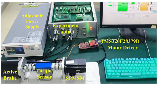
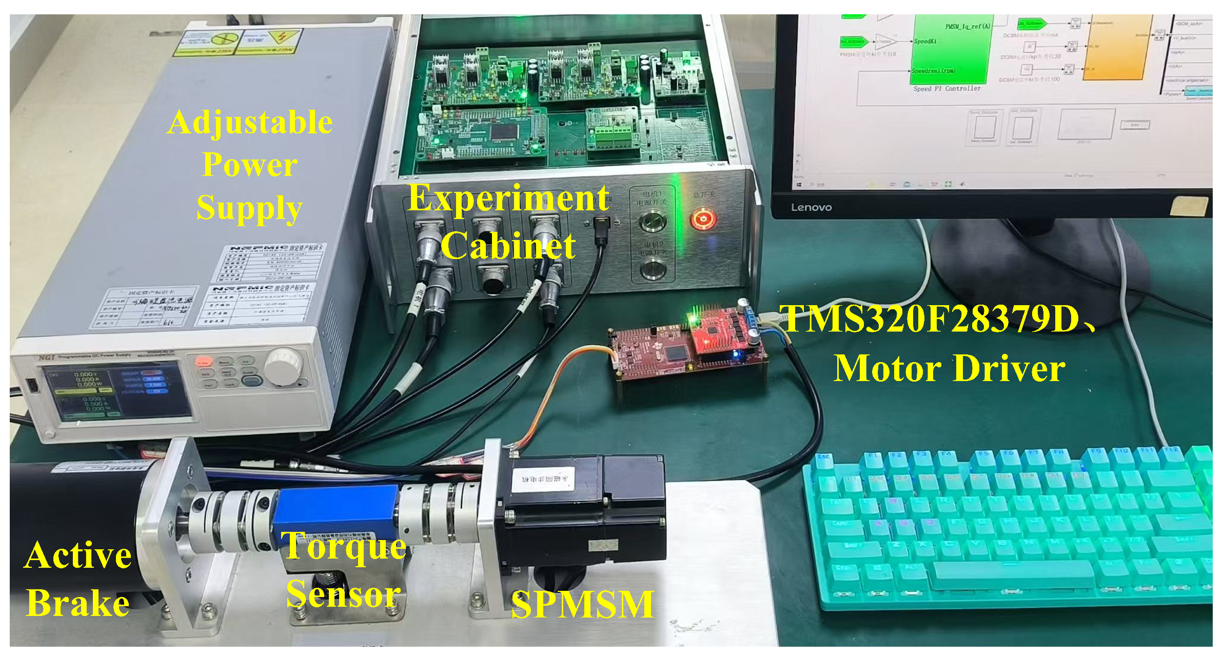
An experimental rig built around the TMS320F28379D chip is established (Figure 2), with a SPMSM serving as the drive unit and a brushed DC motor acting as the active brake. The parameters of the tested SPMSM are summarized in Table 1. The control settings include a 20 kHz switching frequency, a 5 µs dead time, and a 20 kHz current sampling rate. During operation, the chip’s internal data are transmitted to a PC via a serial link in real time for subsequent recording, processing, and analysis.
Figure 2.
Experimental test platform of the PMSM drive with an active brake.
Table 1.
SPMSM parameters.
To verify the effectiveness of the proposed MFPDSC, comparative experiments were carried out on the physical test platform, and the results are compared with those of the conventional PI control and the MFPCC in [16]. The experiments cover three aspects: speed tracking, load disturbance, and parameter sensitivity. The details are as follows.
5.1. Speed Tracking Experiment
The experiment was conducted under a load below 25% of the motor’s rated torque. To evaluate the tracking capability of each algorithm during acceleration and deceleration, speed commands of 0, 600, 1200, 600, and 0 rpm were applied sequentially every 5 s. The system is considered to have reached steady state once the speed error falls within 2% of the reference value.
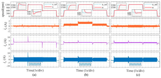
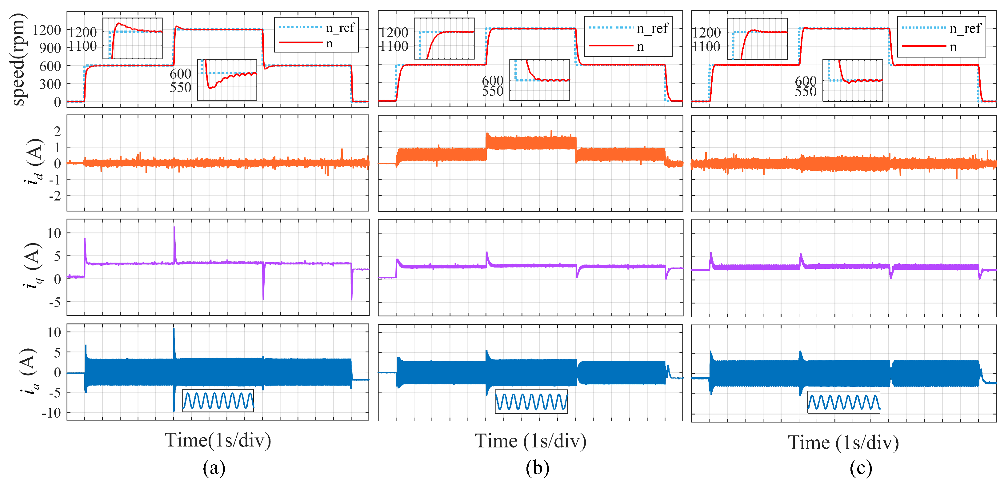
Figure 3 presents the experimental waveforms and data for the three control methods. As shown in Figure 3, during both acceleration and deceleration, MFPDSC exhibits the shortest settling time. Specifically, it takes only 0.226 s to converge to the target speed during the 600 rpm to 1200 rpm phase, and only 0.232 s during the 1200 rpm to 600 rpm phase. This is followed by MFPCC with 0.303 s and 0.351 s, and finally PI with 0.365 s and 0.541 s. The proposed MFPDSC method is significantly superior to PI and MFPCC in speed tracking. From the speed curves, it can be observed that PI control exhibits no overshoot at low speed due to the weak accumulation of integral action; however, in the medium-speed range, under the combined effect of proportional and integral actions, the response becomes faster but is accompanied by noticeable overshoot. Both MFPCC and MFPDSC demonstrate good speed tracking performance. However, MFPCC adopts a cascade control structure, and the cascading of the current loop and speed loop introduces phase lag, resulting in a longer settling time. In contrast, MFPDSC directly integrates the current dynamics into the speed prediction model, eliminating the inherent lag of the cascade structure.
Figure 3.
Experimental results of speed tracking performance test: (a) PI; (b) MFPCC; (c) MFPDSC.
From the current waveforms, it can be seen that the d-axis and q-axis current curves of MFPCC and MFPDSC are thicker than those of PI, which is mainly introduced by the high-frequency compensation of the disturbance observer. Despite a certain degree of pulsation, the current tracking errors are limited to a small range, satisfying the system control requirements. Furthermore, from the three-phase currents, it can be observed that the waveform of the MFPDSC has some distortion. However, as the load increases, these distortions will become smaller, as will be verified in the subsequent load experiments.
5.2. Load Disturbance Experiment
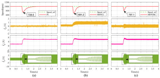
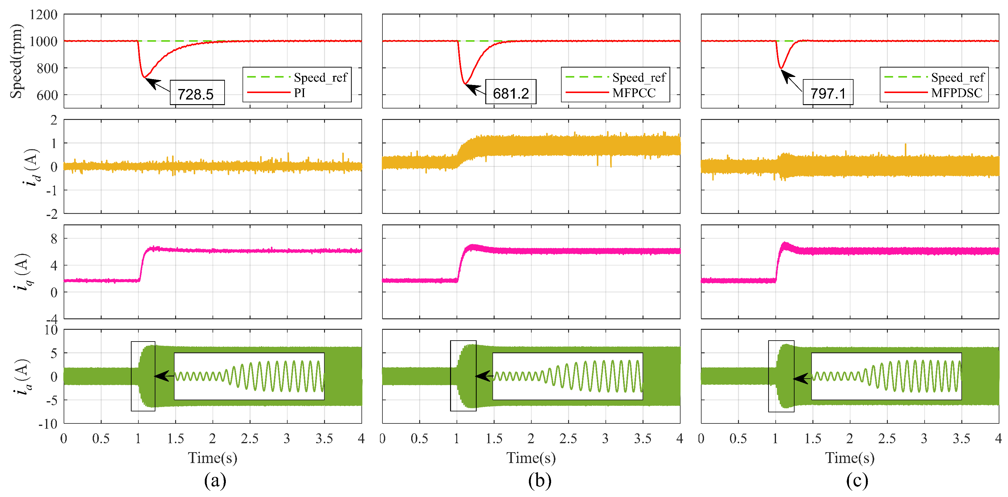
Set the reference speed to 1000 rpm. During the stable operation of the SPMSM, an 80% rated load was suddenly applied, and the speed drop and recovery process were observed. Figure 4 shows the speed and current waveforms of the three control methods under sudden load application. As can be seen from the figure, after the sudden load application, the speed of MFPDSC dropped by 202.9 rpm and quickly recovered to the reference speed within 0.304 s, exhibiting the best performance in both the degree of speed drop and the recovery process. The speed of PI dropped by 271.5 rpm after the sudden load, but its recovery time to the reference speed was the longest, reaching 1.223 s. In contrast, MFPCC suffered the most severe speed drop of 318.8 rpm after the sudden load, but its recovery time to the reference speed was shorter than that of PI, at 0.737 s. The recovery process of PI control is relatively slow, which is mainly attributed to the lag characteristic of the integral action and the difficulty of the proportional action in providing sufficient compensation quickly when the error is small. Although MFPCC has a certain disturbance compensation capability, its cascade structure limits the rapidity of disturbance observation. In MFPDSC, the lumped disturbance observer can dynamically identify and counteract load disturbances. This allows the control output to be updated immediately when a disturbance occurs, thereby limiting the speed fluctuation to a narrow range and ensuring fast recovery. By observing the current waveforms of the three methods, they are basically similar to those in the speed tracking experiment, except that the distortion in the three-phase currents of MFPDSC almost disappears as the load increases.
Figure 4.
Experimental results of anti-load disturbance performance test: (a) PI; (b) MFPCC; (c) MFPDSC.
5.3. Parameter Sensitivity Experiment
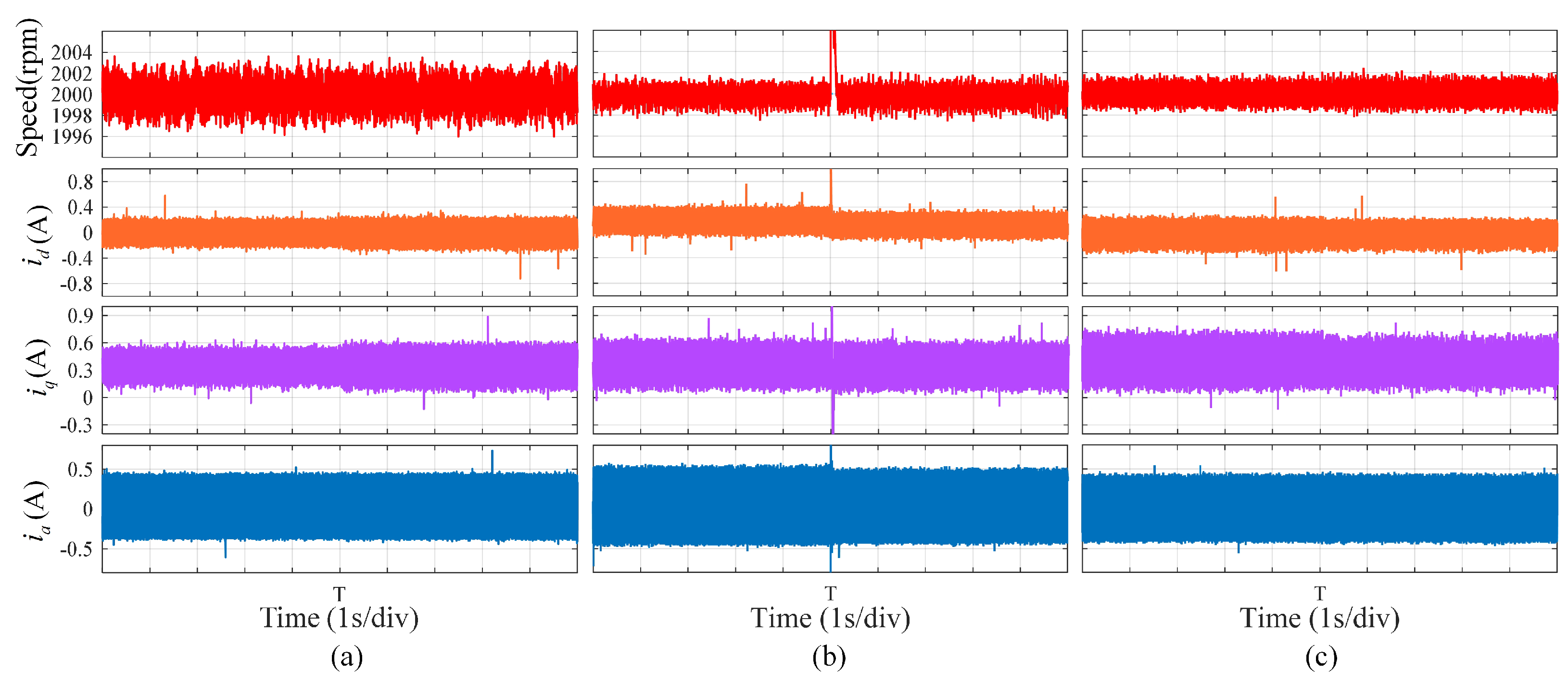
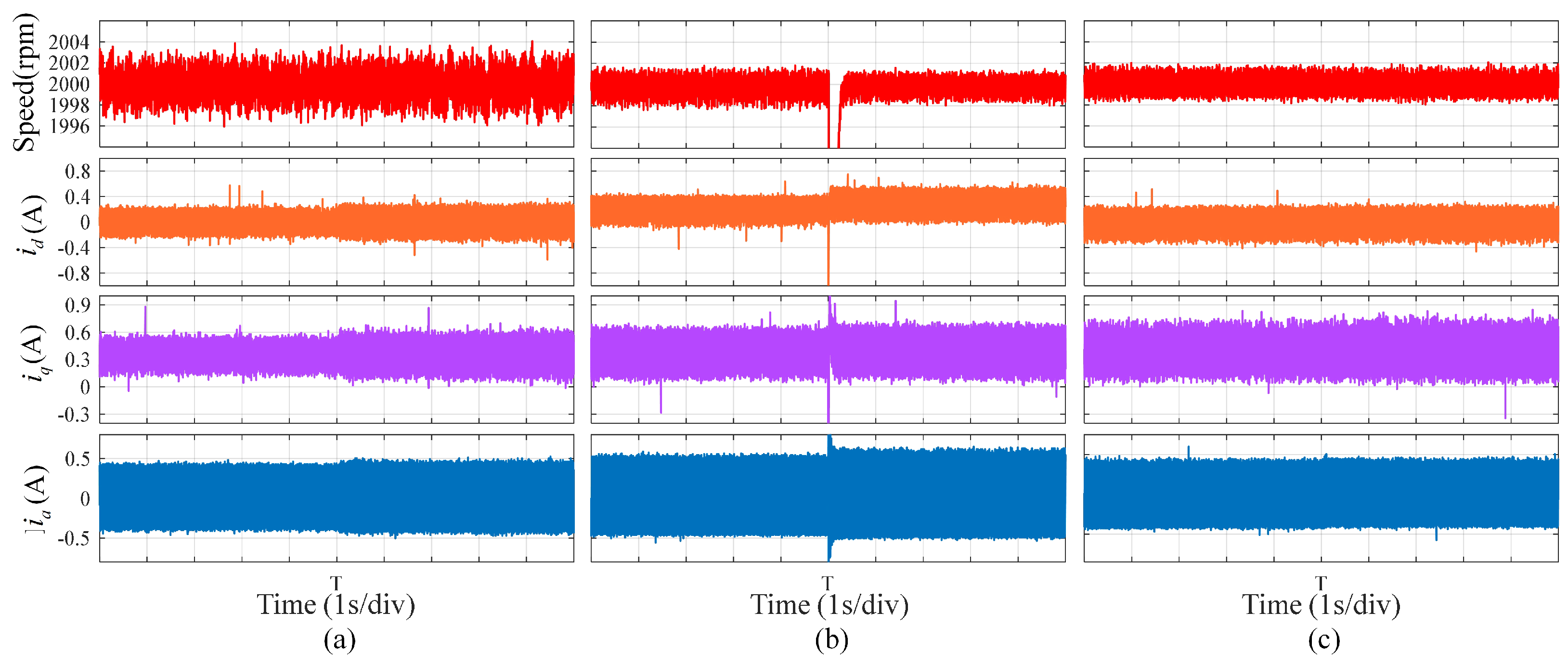
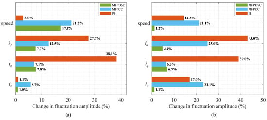
To assess the effect of parameter mismatches on the control system’s response, special attention is paid to inductance variations, as this parameter predominantly affects motor behavior. To avoid the effects of load disturbances, all tests were performed in the absence of any load. Since the physical inductance of a manufactured motor cannot be altered during operation, the parameter mismatch is intentionally introduced in the control algorithm. Under steady-state operation, the inductance value used in the controller and the observer is suddenly stepped to half (0.5×) and twice (2×) its nominal value at time T, while the actual physical inductance of the tested motor remains unchanged. The corresponding transient behavior and steady-state errors of each controller were then recorded. The test outcomes are displayed in Figure 5 and Figure 6, while the comparative outcomes are summarized in Figure 7.
Figure 5.
Experimental results under 0.5-times inductance parameter mutation: (a) PI control; (b) MFPCC; (c) MFPDSC.
Figure 6.
Experimental results under 2-times inductance parameter mutation: (a) PI control; (b) MFPCC; (c) MFPDSC.
Figure 7.
Comparison of experimental data under sudden variation of inductance parameters: (a) is 0.5 times the nominal inductance; (b) is 2 times the nominal inductance.
Upon a sudden reduction in the inductance to half its nominal value, the speed error and phase current amplitude under PI control remained largely unchanged. However, the d-axis current error rose by 27.7%, while the q-axis current error rose by 38.1%. This suggests that although PI achieves strong speed-regulation robustness, parameter mismatches cause a notable rise in current harmonics. For the MFPCC strategy, the speed and current experienced considerable transient surges at the moment of inductance change but quickly recovered to steady state. Its steady-state speed error increased by 21.2%, the d-axis and q-axis currents decreased slightly overall, and the phase current amplitude was reduced by 5.7%. In contrast, under the MFPDSC strategy, the speed error increased by only 17.1%, the d-axis and q-axis current errors decreased by 7.7% and 4.7%, respectively, and the three-phase current amplitude remained essentially unchanged, demonstrating a strong capability to suppress the effects of inductance variation.
When the inductance was suddenly increased to twice its original value, the speed error of the PI control increased by 14.3%, the d-axis and q-axis current errors increased by 43% and 39%, respectively, and the phase current amplitude increased by 17%. For the MFPCC strategy, after the parameter change, the speed error decreased by 21.1%, but the d-axis and q-axis current errors increased by 25% and 6.3%, respectively, and the three-phase current amplitude increased by 23.1%. In contrast, under the MFPDSC strategy, the speed error showed no significant change; the d-axis and q-axis current errors increased by only 4.8% and 6.9%, respectively, and the three-phase current amplitude remained essentially unchanged. Summarizing the above experimental results, PI control exhibits a certain degree of robustness to parameter variations, but the current quality is susceptible to inductance mismatch. MFPCC remains relatively dependent on the inductance parameters, with noticeable deterioration in current performance under parameter mismatch, and the performance changes are asymmetric for mismatch in different directions. By contrast, MFPDSC benefits from its model-free architecture and the lumped disturbance observer, which enables it to counteract parameter variations dynamically. As a result, it exhibits low sensitivity in both speed and current regulation, confirming the advantage of the proposed method under parameter mismatches.
6. Conclusions
This paper proposes an MFPDSC method for SPMSMs. By constructing a direct speed ultra-local model that integrates current dynamics, the traditional cascade control structure is simplified into a single-loop speed predictive control, eliminating the coupling between the speed loop and the current loop. Meanwhile, a combination of data-driven estimation and a RESO is adopted to estimate and compensate for the lumped disturbance, enhancing the system’s robustness against parameter perturbations and unmodeled dynamics. Experimental results demonstrate that the proposed MFPDSC exhibits significant advantages under operating conditions characterized by frequent speed variations, sudden load changes, and parameter uncertainties. Its model-free architecture and lumped disturbance observer enable fast dynamic tracking and strong robustness without requiring precise motor parameters. However, the proposed method still has certain limitations. For instance, under extremely low-speed conditions, the speed fluctuation is relatively large, making it more suitable for medium- and high-speed applications. Second, the three-phase current exhibits more noticeable distortion under light-load conditions, which needs to be mitigated by other methods, such as dead-time compensation. Future work will focus on replacing the continuous control set predictive control with a finite control set predictive control output, and combining it with optimization algorithms to achieve automatic parameter tuning. These efforts will further enhance the practical applicability and robustness of the proposed method in more complex industrial environments.
Author Contributions
Conceptualization, H.H.; methodology, H.H., W.G. and F.F.; software, W.G., F.F. and Y.C. (Yuquan Chen); validation, W.G., Y.C. (Yuquan Chen) and Y.C. (Yuhui Chen); formal analysis, H.H., W.G. and F.F.; investigation, W.G., F.F., Y.C. (Yuquan Chen) and Y.C. (Yuhui Chen); resources, H.H.; data curation, W.G., Y.C. (Yuquan Chen) and Y.C. (Yuhui Chen); writing—original draft preparation, W.G.; writing—review and editing, H.H., F.F. and Y.C. (Yuhui Chen); visualization, W.G. and Y.C. (Yuquan Chen); supervision, H.H. and F.F.; project administration, F.F.; funding acquisition, H.H. and F.F.; All authors have read and agreed to the published version of the manuscript.
Funding
This work was supported in part by the project “Research on Model Predictive Control Strategy for Rare Earth Permanent Magnet Motors with Synergistic Dynamic Performance and Efficiency” (Grant No. 20262BEJ730237), and in part by the Ganzhou Rare Earth New Materials and Application Industry Development Alliance (Grant No. XTLM202512).
Institutional Review Board Statement
Not applicable.
Informed Consent Statement
Not applicable.
Data Availability Statement
Data are contained within the article.
Conflicts of Interest
The authors declare no conflict of interest.
Abbreviations
The following abbreviations are used in this manuscript:
| SPMSM | surface-mounted permanent magnet synchronous motors |
| ESO | extended state observer |
| RESO | reduced-order extended state observer |
| HESO | high-order extended state observer |
| MPC | model predictive control |
| MFPCC | Model-free predictive current control |
| MFPDSC | model-free predictive direct speed control |
References
- Li, L.N.; Zhu, G.J. Electromagnetic-Thermal-Stress Efforts of Stator-Casing Grease Buffers for Permanent Magnet Driving Motors. IEEE Trans. Ind. Appl. 2023, 60, 1268–1276. [Google Scholar] [CrossRef] [Scilit]
- Rodríguez, J.R.; Garcia, C.; Mora, A.; Flores-Bahamonde, F.; Acuna, P.; Novak, M.; Zhang, Y.C.; Tarisciotti, L.; Alireza, D.S.; Zhang, Z.B.; et al. Latest Advances of Model Predictive Control in Electrical Drives - Part I: Basic Concepts and Advanced Strategies. IEEE Trans. Power Electron. 2022, 37, 3927. [Google Scholar] [CrossRef] [Scilit]
- An, X.K.; Liu, G.H.; Chen, Q.; Zhao, W.X.; Song, X.J. Adjustable Model Predictive Control for IPMSM Drives Based on Online Stator Inductance Identification. IEEE Trans. Ind. Electron. 2022, 69, 3368–3381. [Google Scholar] [CrossRef] [Scilit]
- Chen, X.; Zhang, S.; Zhao, M.W.; Zhao, Y.; Zhou, Y.; Wang, S.L.; Zhang, X.D. A Parameter Identification Method Based on Reduced-Order Observer for SPMSM With Deadbeat Predictive Current Control. IEEE Trans. Power Electron. 2026, 41, 5151–5161. [Google Scholar] [CrossRef] [Scilit]
- Xu, A.D.; Liu, R.J.; Yu, Y.B. Three-Vector Model Predictive Current Control of Permanent Magnet Assisted Synchronous Reluctance Motor Based on Step-by-Step Parameter Identification. Prog. Electromagn. Res. C 2025, 151, 177–184. [Google Scholar] [CrossRef] [Scilit]
- Tan, Z.X.; Liu, L.; Li, Y.J.; He, F.; Liu, B.Y.; Yi, Z.X. A Robust Model Predictive Current Control Strategy with Improved Adaptive Quantum Genetic Algorithm-Based Parameter Identification for PMSM. IEEE Trans. Energy Convers. 2026, 41, 414–426. [Google Scholar] [CrossRef] [Scilit]
- Wang, F.X.; Wei, Y.; Rodriguez, J.; Garcia, C. State-of-Art, Development, and Challenges of Model-Free Predictive Control on Motor Drives. IEEE Trans. Power Electron. 2025, 40, 10846–10864. [Google Scholar] [CrossRef] [Scilit]
- Liu, X.; Yang, H.; Cai, S.; Lin, H.Y.; Yu, F.; Yang, Y. A Novel Finite-Control-Set Model-Free Predictive Current Control Incorporating Event Triggering Mechanism for PMSM Drives. IEEE Trans. Ind. Appl. 2025, 61, 322–334. [Google Scholar] [CrossRef] [Scilit]
- Yang, H.T.; Zhang, Y.C.; Shen, W.J. Predictive Current Control and Field-weakening Operation of SPMSM Drives without Motor Parameters and DC Voltage. IEEE J. Emerg. Sel. Top. Power Electron. 2022, 10, 5635–5646. [Google Scholar] [CrossRef] [Scilit]
- Luo, B.; Yang, X.B.; Zhou, Y. Model-Free Predictive Current Control of Permanent Magnet Synchronous Motor Based on Estimation of Current Variations. IEEE Trans. Ind. Electron. 2024, 71, 8395–8405. [Google Scholar] [CrossRef] [Scilit]
- Wei, Y.; Ke, D.L.; Huang, D.X.; Wang, F.X.; Zhang, Z.B. Model-Free Predictive Sliding Mode Control Using Ultra-Localized Time-Series for Permanent Magnet Synchronous Motor Drives. Diangong Jishu Xuebao/Transactions China Electrotech. Soc. 2024, 39, 1022–1032. [Google Scholar]
- Wei, Y.; Young, H.; Wang, F.X.; Rodríguez, J. Generalized Data-Driven Model-Free Predictive Control for Electrical Drive Systems. IEEE Trans. Ind. Electron. 2023, 70, 7642–7652. [Google Scholar] [CrossRef] [Scilit]
- Wei, Y.; Ke, D.L.; Huang, D.X.; Wang, F.X.; Kang, J.S. A Continuous-Control-Set Type Model-Free Predictive Current Control Based on Time-Series for Permanent Magnet Synchronous Motor Drives. Diangong Jishu Xuebao/Transactions China Electrotech. Soc. 2023, 38, 6027–6038. [Google Scholar]
- Wang, D.M.; Shen, Z.J.; Yin, X.; Tang, S.; Liu, X.F.; Zhang, C.; Wang, J.; Rodriguez, J.; Norambuena, M. Model Predictive Control Using Artificial Neural Network for Power Converters. IEEE Trans. Ind. Electron. 2022, 69, 3689–3699. [Google Scholar] [CrossRef] [Scilit]
- Ahmed, H.M.; Jlassi, I.; Cardoso, A.J.M.; Bentaallah, A. Model-Free Predictive Current Control of Synchronous Reluctance Motors Based on a Recurrent Neural Network. IEEE Trans. Ind. Electron. 2022, 69, 10984–10992. [Google Scholar] [CrossRef] [Scilit]
- Zhang, Y.C.; Jin, J.L.; Huang, L.L. Model-Free Predictive Current Control of PMSM Drives Based on Extended State Observer Using Ultralocal Model. IEEE Trans. Ind. Electron. 2021, 68, 993–1003. [Google Scholar] [CrossRef] [Scilit]
- Kang, J.S.; Huang, X.Y.; Xia, C.; Huang, D.X.; Wang, F.X. Ultralocal Model-Free Adaptive Supertwisting Nonsingular Terminal Sliding Mode Control for Magnetic Levitation System. IEEE Trans. Ind. Electron. 2023, 71, 5187–5194. [Google Scholar] [CrossRef] [Scilit]
- Liu, J.Q.; Yang, Y.; Li, X.F.; Zhao, K.H.; Yi, Z.X.; Xin, Z. Improved Model-Free Continuous Super-Twisting Non-singular Fast Terminal Sliding Mode Control of IPMSM. IEEE Access 2023, 11, 85361–85373. [Google Scholar] [CrossRef] [Scilit]
- Liu, Z.X.; Huang, X.Y.; Hu, Q.C.; Yang, G.; Wang, Y.C.; Shen, J.X. Model-Free Predictive Current Control of PMSM Using Modified Extended State Observer. IEEE Trans. Power Electron. 2024, 40, 679–690. [Google Scholar] [CrossRef] [Scilit]
- Liu, X.C.; Wang, J.; Gao, X.N.; Tian, W.; Zhou, L.B.; Rodriguez, J.; Kennel, R. Continuous Control Set Predictive Speed Control of SPMSM Drives with Short Prediction Horizon. IEEE Trans. Power Electron. 2022, 37, 10166–10177. [Google Scholar] [CrossRef] [Scilit]
- Preindl, M.; Bolognani, S. Model Predictive Direct Speed Control with Finite Control Set of PMSM Drive Systems. IEEE Trans. Power Electron. 2013, 28, 1007–1015. [Google Scholar] [CrossRef] [Scilit]
- Zerdali, E.; Ardjoun, S.A.E.M.; Rivera, M.; Riccio, J.; Bonaldo, J.; Wheeler, P. Sensorless Sequential Model Predictive Direct Speed Control for Induction Motor Drives. In IEEE Transactions on Industrial Electronics; IEEE: New York, NY, USA, 2026; pp. 1–12. [Google Scholar]
- Zhao, M.Y.; Cao, Y.F.; Li, C.; Wang, Z.Q.; Shi, T.N.; Xia, C.L. Expanded Limit Boundary Explicit Model Predictive Direct Speed Control for PMSMs. IEEE Trans. Power Electron. 2024, 39, 6089–6101. [Google Scholar] [CrossRef] [Scilit]
- Zheng, C.M.; Yang, J.F.; Gong, Z.; Xiao, Z.Y.; Dong, X.X. Cascade-Free Modulated Predictive Direct Speed Control of PMSM Drives. Energies 2022, 15, 7200. [Google Scholar] [CrossRef] [Scilit]
- Shi, T.N.; Zhao, M.Y.; Xia, C.L. Explicit Model Predictive Direct Speed Control Strategy for Permanent Magnet Synchronous Motors Based on Data Driven Observer. Zhongguo Dianji Gongcheng Xuebao/ Proc. Chin. Soc. Electr. Eng. 2025, 45, 1248–1259. [Google Scholar]
- Zhang, Z.R.; Zhang, Q.Y.; Wang, X.Y.; Xu, J. Model-free Predictive Direct Speed Control Method for Surface-mounted Permanent Magnet Synchronous Motors. Zhongguo Dianji Gongcheng Xuebao/Proceedings Chin. Soc. Electr. Eng. 2026, 46, 1651–1661. [Google Scholar]
- Yang, M.Z.; Wang, P.D.; Huang, S.; Liao, W.; Wu, X.; Liang, G.; Wu, T.; Liu, X.C.; Li, X.; Huang, S.D. Multivector-Based Model-Free Predictive Speed Control With Disturbance Suppression and Weighting Factor Elimination for SPMSM. IEEE Trans. Transp. Electrif. 2025, 11, 1730–1742. [Google Scholar] [CrossRef] [Scilit]
- Cheng, S.; Zhou, R.R.; Xiang, C.Q.; Li, Z.X.; Xi, Z. Model-Free Predictive Direct Speed Control for SPMSM Drives. In Proceedings of the IEEE International Power Electronics and Application Conference and Exposition; IEEE: New York, NY, USA, 2022. [Google Scholar]
- Hou, Q.K.; Wang, H.Z.; Lee, C.H.T.; Ding, S.H. Composite Adaptive Super-Twisting Sliding Mode Control Using Barrier Function for PM Motor Drives Toward Electric Aircraft Applications. IEEE Trans. Power Electron. 2025, 40, 16255–16264. [Google Scholar] [CrossRef] [Scilit]
- Hou, Q.K.; Wang, H.Z.; Zhao, C.H.; Xu, S.K.; Zuo, Y.F.; Lee, C.H.T.; Ding, S.H. Super-twisting Extended State Observer Based Quasi-Proportional-Resonant Controller for Permanent Magnet Synchronous Motor Drive System. IEEE Trans. Transp. Electrif. 2023, 40, 1596–1604. [Google Scholar] [CrossRef] [Scilit]

Disclaimer/Publisher’s Note: The statements, opinions and data contained in all publications are solely those of the individual author(s) and contributor(s) and not of MDPI and/or the editor(s). MDPI and/or the editor(s) disclaim responsibility for any injury to people or property resulting from any ideas, methods, instructions or products referred to in the content. |
© 2026 by the authors. Licensee MDPI, Basel, Switzerland. This article is an open access article distributed under the terms and conditions of the Creative Commons Attribution (CC BY) license.