


Abstract
In engineered cementitious composites (ECCs), the use of fine quartz sand is associated with high cost and is unfavorable for reducing ECC shrinkage. Moreover, the mining and processing of fine quartz sand impose negative environmental impacts. At the same time, the polyethylene (PE) or polyvinyl alcohol (PVA) fibers added to ensure ECC ductility are expensive, which limits the widespread application of ECCs. With the aim of waste utilization and cost reduction while improving efficiency, this study employs geopolymer aggregate (GPA) as an alternative to fine quartz sand and partially replaces PE fibers with steel fibers to develop an economical and environmentally friendly geopolymer aggregate ECC. Six groups of ECC specimens with different mix proportions were designed and tested under uniaxial compression, flexural loading, and uniaxial tension. Different aggregate types (fine quartz sand and geopolymer aggregate) and volume fraction ratios of PE fibers to steel fibers (0:2.0, 0.5:1.5, 1.0:1.0, 1.5:0.5, and 2.0:0) were adopted to investigate their effects on mechanical properties, microstructural characteristics, and material sustainability. The experimental results reveal the failure process and deformation characteristics of the ECCs at different loading stages. The results indicate that geopolymer aggregate, owing to its lower stiffness and fracture energy, can promote multiple cracking behavior in ECCs. Although the complete replacement of quartz sand with porous GPA initially causes a slight reduction in the compressive and flexural strengths of the matrix, the hybridization strategy—partially replacing PE fibers with steel fibers—effectively compensates for this strength loss while maintaining excellent ductility. By comparing sustainability indicators with those of conventional ECCs, the results demonstrate that hybrid fiber geopolymer aggregate ECCs can effectively reduce material costs and carbon dioxide emissions. These findings verify the sustainability of producing green ECCs using industrial solid waste as an aggregate and provide guidance for the application of environmentally friendly geopolymer aggregate ECCs.
1. Introduction
Concrete materials, while widely used in the construction industry, exhibit limitations such as low tensile strength and poor ductility, which restrict their application in environmentally friendly and durable engineering structures. Engineering cementitious composites (ECCs), designed based on micro-mechanics and fracture mechanics theories, are fiber-reinforced cementitious materials capable of achieving strain hardening and multiple cracking under tensile loads [1,2,3]. In comparison to ordinary concrete with a tensile strain of approximately 0.05%, ECCs can exhibit tensile strains ranging from 1% to 5% [4,5]. ECCs effectively overcome the shortcomings of traditional concrete by offering good durability and reducing the maintenance frequency of engineering structures [6,7,8]. Under complex environmental conditions, particularly in marine and corrosive environments, ECCs demonstrate significant potential for widespread application. Furthermore, owing to their exceptional damage tolerance and ductile behavior, ECCs have been increasingly utilized in various advanced structural applications, such as novel composite columns, structural joints, and structural retrofitting [9,10,11].
The preparation of ECCs typically utilizes silica sand (SS) as fine aggregates; however, the limited sources of silica sand and the increased carbon emissions and production costs associated with long-distance transportation hinder the widespread adoption of ECCs [12]. Therefore, the development of an environmentally friendly ECC has become urgent. Geopolymer aggregate (GPA), as a solid waste material, has been considered a viable alternative to silica sand for producing ECCs, while also aiding in the substantial utilization of industrial solid waste. In recent years, numerous studies have been conducted both domestically and internationally on the replacement of natural river sand with GPA in the preparation of cement-based materials [13]. Huang et al. [7] conducted accelerated aging tests on two types of ECC using GPA and fine silica sand, revealing that the strength of both materials was comparable, and the long-term tensile performance of GPA-ECC was superior. The porous nature of GPA facilitates internal curing by releasing water for the secondary hydration of the cementitious material, thus enhancing the long-term durability of the ECC. Xu et al. [14] found that during the development of a GPA-ECC, GPA could lower the matrix’s fracture toughness and induce crack propagation.
Furthermore, compared to natural aggregates, GPA typically exhibits lower stiffness and fracture energy [13]. Direct use of GPAs in ordinary concrete may result in significant strength reduction. This is because ordinary concrete lacks high-volume fiber bridging, and the pores introduced by GPA tend to cause severe stress concentration, ultimately leading to brittle failure. However, in the micromechanical design of ECCs, the dense hybrid fiber network can effectively stitch the micro-cracks induced by GPA pores, fundamentally transforming these “defects” into advantageous triggers for steady-state multiple cracking. To alleviate these adverse effects, incorporating fibers has proven to be an effective strategy to maintain strength on par with silica sand-based ECCs. Existing studies indicate that hybrid fiber reinforced concrete offers distinct advantages over mono-fiber concrete in specific performance indicators. Researchers such as Mohammed, Pakravan, and Ahmed [15,16,17] have confirmed that the multi-scale fiber hybrid effect can enhance the tensile strength, ultimate tensile strain, and flexural toughness index of concrete. Notably, the bond strength at the steel fiber–matrix interface can reach 9.7 MPa [18], providing more effective crack width suppression compared to polymer fibers. The synergistic effects of different fiber types and sizes can create a multi-level crack resistance mechanism: steel fibers primarily hinder macroscopic crack propagation while polymer fibers control micro-crack development [19]. Some researchers have utilized a steel–polymer hybrid fiber system to prepare ECCs and found that the synergistic effect could reduce crack widths to 50–80 μm (40–60% smaller than those with single PE fibers), while mitigating drying shrinkage rates to 600–800 με [20].
In light of these findings, this study employs geopolymer aggregate as a substitute for fine silica sand and utilizes low-cost steel fibers to partially replace PE fibers, aiming to develop an economical, low-carbon hybrid fiber geopolymer aggregate ECC based on the concept of “waste utilization.” A systematic investigation is conducted on the effects of steel fiber and PE fiber dosage ratio, as well as aggregate type, on the mechanical properties of ECCs. Additionally, scanning electron microscope (SEM) technology is employed for microstructural analysis. Finally, the sustainability of the hybrid fiber geopolymer aggregate ECC is demonstrated using the material sustainability index (MSI). This research not only promotes the application of ECCs in green engineering but also opens new avenues for the resource utilization of geopolymer aggregates.
2. Materials and Methods
2.1. Geopolymer Aggregate
2.1.1. Geopolymer Aggregate Mix Proportion
A total of nine groups of geopolymer aggregates was designed and categorized into two types according to the raw materials used as precursors. The proportions of each component are listed in Table 1. The first type utilized fly ash (FA) as the sole precursor to investigate the effect of alkalinity on the properties of geopolymer aggregates, with the mass ratio of alkali activator to precursor varied between 8% and 16%. In the nomenclature, “FA–nAA” denotes fly ash-based geopolymer aggregates prepared with n% anhydrous sodium metasilicate (AA) as the alkali activator. The second type focused on examining the influence of the ground granulated blast-furnace slag (GGBS) replacement ratio on geopolymer aggregate properties. The incorporation of GGBS can enhance the interfacial bonding between aggregates and the cementitious matrix. In this group, the precursor materials were composed of both fly ash (FA) and GGBS [21]. The notation “mS–nAA” indicates geopolymer aggregates synthesized with a precursor consisting of (100–m)% FA and (m)% GGBS, where n% represents the mass ratio of alkali activator to the precursor materials.
Table 1.
Geopolymer aggregate mix proportions.
2.1.2. Preparation Process for Geopolymer Aggregates
According to the experimental procedure, the geopolymer aggregate (GPA) was prepared using a single-component mixing technique. The preparation process was as follows: (1) Anhydrous sodium metasilicate granules, mineral powder, and fly ash were added into a stirring vessel and dry-mixed for 3 min to achieve thorough homogenization. (2) Water was then added and stirred for 5 min until a uniform, free-flowing gray slurry was obtained, which was poured into molds for casting. For each of the nine groups of geopolymer aggregate, three cubic specimens were prepared, and their 1-day compressive strengths were measured and recorded. (3) After standard curing for one day, the specimens were crushed to a particle size below 4.75 mm and placed in a drying oven at a constant temperature of 70 °C for 48 h. (4) Upon completion of drying, the specimens were sealed in airtight bags and stored for 28 days for subsequent use.
2.1.3. Geopolymer Aggregates’ 1-Day Compressive Strength
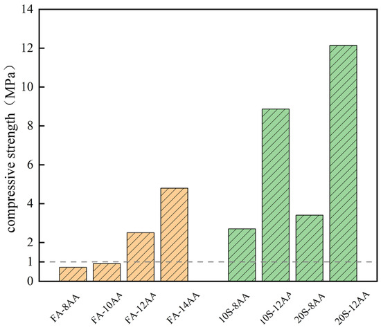
The crushing energy of geopolymer aggregates is associated with the early age strength of the geopolymer [22]; higher strength requires greater energy input during crushing, which evidently increases economic costs. Meanwhile, a certain early age strength is necessary to ensure the integrity of the geopolymer aggregates. In this section, the 1-day compressive strength of nine geopolymer mixtures was tested to evaluate the influence of alkali content and GGBS on early age strength [23]. The 1-day compressive strength results are shown in Figure 1.
Figure 1.
Geopolymer aggregates 1d compressive strength.
When fly ash was used as the sole precursor, the 1-day compressive strengths were 0.7 MPa and 0.9 MPa at alkali contents of 8% and 10%, respectively, which are far below the minimum acceptable level. Increasing the alkali content to 12% led to a rapid rise in strength to 2.5 MPa, indicating a pronounced improvement. The maximum strength of 6.5 MPa was obtained at an alkali content of 16%. Overall, the 1-day compressive strength increased with higher alkali content, with the highest value observed at 16%.
At an alkali content of 8%, replacing 10% and 20% of the fly ash with GGBS increased the 1-day compressive strength by 285.7% and 385.7%, respectively, compared with the mixture containing only fly ash. At an alkali content of 12%, the corresponding increases were 256.0% and 388.0%. The highest 1-day compressive strength was achieved when 20% of fly ash was replaced with GGBFS at an alkali content of 12%.
Although increasing alkali content significantly enhances the 1-day compressive strength, excessively high strength is not desirable considering the energy required for manual crushing and the need to maintain aggregate integrity. Furthermore, an overly high alkali content may disrupt the C–S–H chains [24], thereby reducing the bonding strength between geopolymer aggregates and the cementitious matrix.
2.1.4. Assessment of Embodied Carbon Emissions of Geopolymer Aggregates
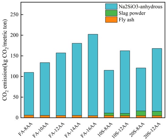
The embodied carbon data of raw materials for geopolymer aggregates are presented in Table 2, which includes the embodied carbon emissions of fly ash [25], slag powder [26], sodium metasilicate anhydrous [27], and water [28]. Among these, sodium metasilicate anhydrous is identified as the primary source of carbon emissions during the production of geopolymer aggregates [29]. Based on the carbon content data provided in Table 2, the embodied carbon emissions of the nine groups of geopolymer aggregates with different mix proportions were estimated, and the results are illustrated in Figure 2. For geopolymer aggregates prepared using only fly ash as the precursor, the total carbon emissions gradually increase with higher alkali content. Since the carbon emissions from fly ash are considerably lower than those from sodium metasilicate anhydrous, its influence on the overall carbon emissions is minimal. For geopolymer aggregates in which 10% and 20% of fly ash is replaced by slag powder as the precursor, the embodied carbon emissions also show a gradual increasing trend with rising alkali content.
Table 2.
Embodied carbon of raw materials.
Figure 2.
Embodied carbon emissions of geopolymer aggregates.
2.1.5. Mix Proportion Design of Geopolymer Aggregates
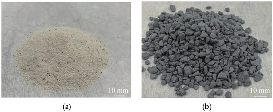
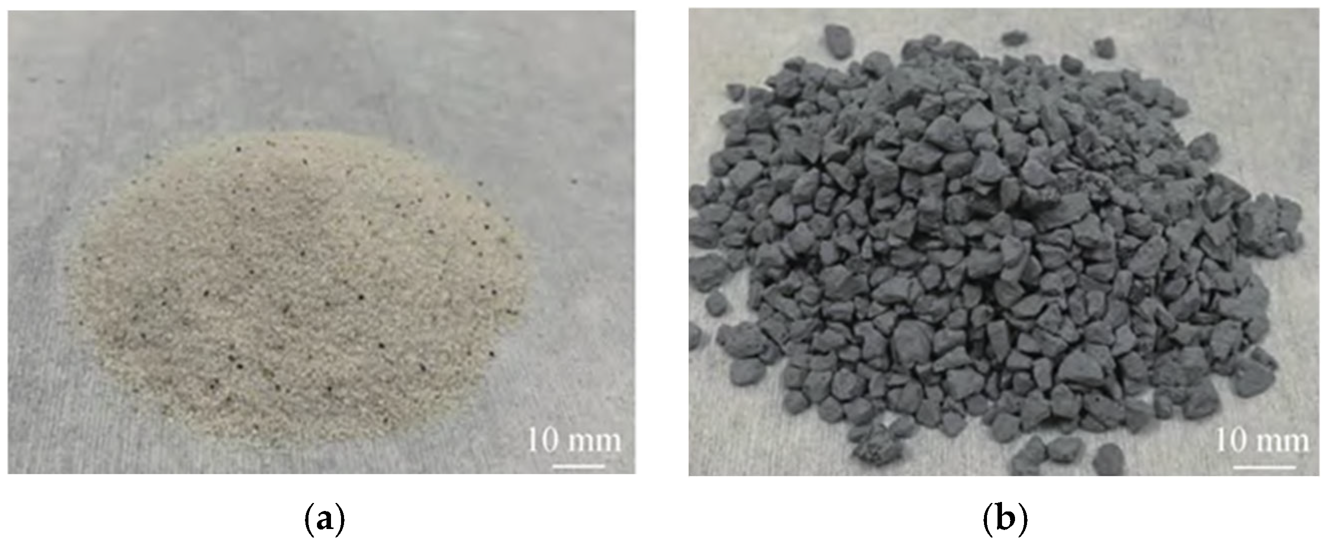
Based on the comprehensive test results from Section 2.1.3 and Section 2.1.4, the mixture selection of geopolymer aggregates must strike a balance between mechanical robustness and environmental impact. Specifically, the 1-day compressive strength dictates the mechanical feasibility for the crushing process and aggregate integrity, while the alkali activator content fundamentally determines the embodied carbon emissions. Guided by these two critical premises, a comparative analysis of the experimental data revealed that for geopolymer aggregates utilizing solely fly ash as the precursor, the lower alkali contents of FA-8AA and FA-10AA were detrimental to early age strength development. Comparative analysis of the experimental data revealed that for geopolymer aggregates utilizing solely fly ash as the precursor, the lower alkali contents of FA-8AA and FA-10AA were detrimental to the development of mechanical properties. Conversely, the FA-14AA and FA-16AA mixes exhibited excessively high embodied carbon emissions. The increased alkalinity in these two groups would lead to excessively high energy consumption during the geopolymer aggregate preparation process, which is unfavorable for industrial-scale production. Therefore, 12% alkali content is more conducive to engineering promotion and practical application. For geopolymer aggregates where 10% and 20% of fly ash was replaced by slag powder as the precursor, the overall performance of the latter was superior to the former at an identical alkali content. Notably, the 20S-12AA mix demonstrated the highest compatibility with the engineered cementitious composite (ECC) among the nine groups of geopolymer aggregates. The morphologies of the quartz sand aggregate and the geopolymer aggregates (GPA) are presented in Figure 3. The mix proportion design of geopolymer aggregate is shown in Table 3.
Figure 3.
Morphology of (a) silica sand and (b) GPA.
Table 3.
Mix proportion design of GPA.
2.2. Materials
2.2.1. Raw Materials of ECC
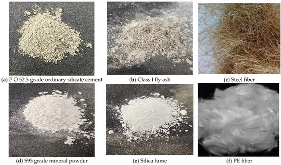
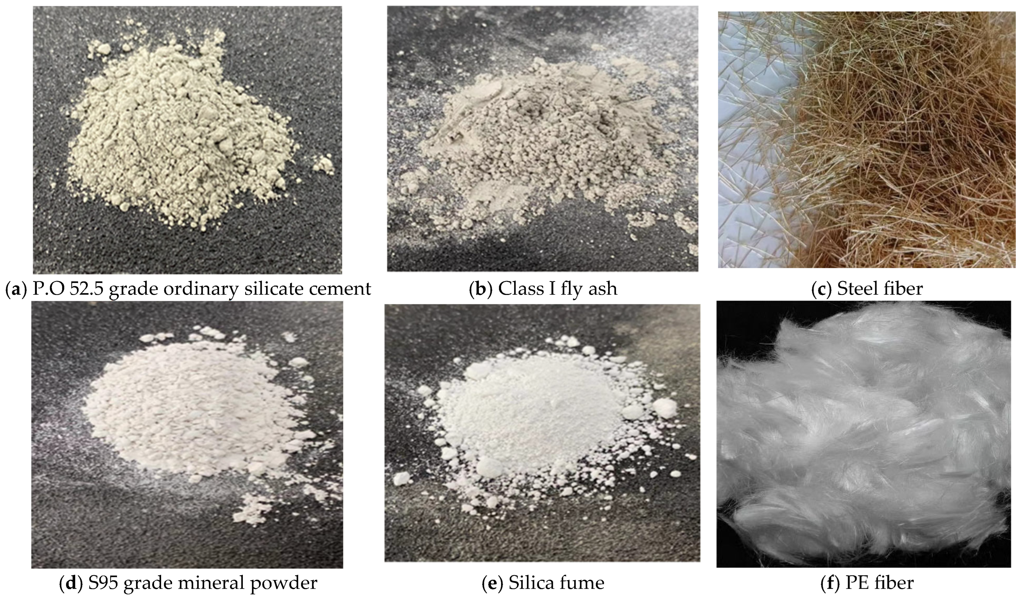
The raw materials primarily included Portland cement grade P·O 52.5 (ordinary Portland cement, OPC) produced by Zhucheng Yangchun Cement Co. Ltd. (Weifang, China). We also used class I fly ash, S95-grade ground granulated blast-furnace slag, and silica fume (SF) (Xingyang Jinyu Building Materials Co., Ltd., Zhengzhou, Henan, China). The chemical compositions of these raw materials are presented in Table 4. The alkali activator was industrial-grade sodium metasilicate anhydrous (Na2SiO3-anhydrous) particles supplied by Qingdao Gulf Chemical Co. Ltd. (Qingdao, China), with a mass fraction of 46.60% for SiO2 and 51.11% for Na2O. The properties of the ultra-high-molecular-weight polyethylene (PE) fibers (Changzhou Lantian Fiber Co., Ltd., Changzhou, Jiangsu, China.) are listed in Table 5, and the properties of the steel fibers (Changzhou Tianniu Steel Fiber Co., Ltd., Changzhou, Jiangsu, China.) are shown in Table 6. A highly effective polycarboxylic acid-based water reducer (PR) (Jiangsu Sobute New Materials Co., Ltd., Nanjing, Jiangsu, China) with a water reduction rate exceeding 25% was used. The geopolymer aggregates (GPAs) were self-manufactured. In accordance with existing research [19], the particle size of all GPAs was selected to be below 4.75 mm. The 24 h water absorption of the GPA was 24.6%. The apparent density of the quartz sand (SS) (Laizhou Guangyu Mining Co., Ltd., Yantai, Shandong, China.) was 2255.3 kg/m3, with a 24 h water absorption of 0.8%. Tap water was used throughout the experiments. The morphologies of the raw materials are presented in Figure 4.
Table 4.
Chemical composition of raw materials.
Table 5.
Performance index of PE fiber.
Table 6.
Performance index of steel fiber.
Figure 4.
Images of raw materials.
2.2.2. ECC Mix Proportions
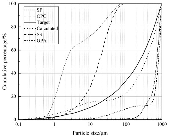
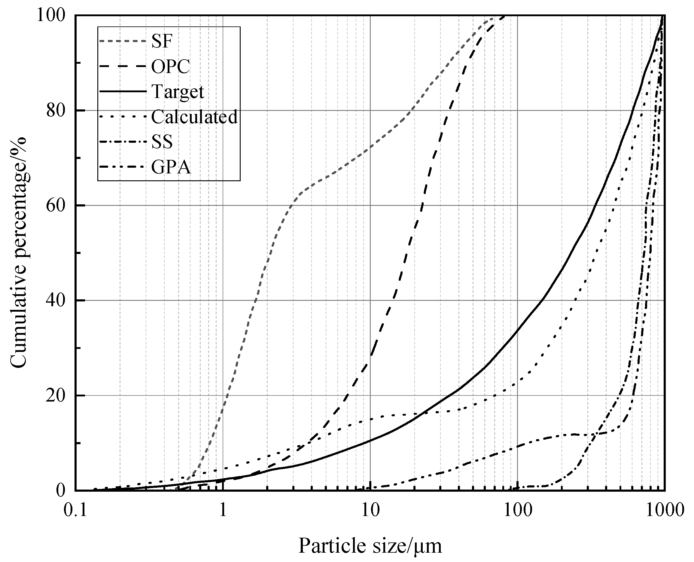
To achieve high compressive strength in the ECC, the particle size distribution of raw materials was obtained using a laser particle size analyzer and standard sieves. The matrix mix proportions were designed with reference to the widely accepted Modified Andreasen and Andersen (MAA) model from ultra-high-performance concrete, as detailed in Table 7. The water-to-binder ratio and sand-to-binder ratio were 0.17 and 0.24, respectively, with a fiber volume fraction of 2%. The cumulative particle size distribution of the raw materials, along with the actual packing curves of each mix proportion and the target curve from the MAA model, are presented in Figure 5.
Table 7.
Mix proportion of ECCs.
Figure 5.
Raw material particle size distribution and application of MAA model in the design of ECC matrix mix proportion.
This study investigated the effects of two aggregate types (GPA and quartz sand) and hybrid fiber reinforcement (PE fibers and ST fibers) at five volume fractions (ST fiber incorporations of 0%, 0.5%, 1%, 1.5%, and 2%) on the compressive strength, flexural strength, tensile strength, and deformation properties of ECCs. A total of six mix proportions were formulated. For each mix proportion, three cubic specimens, three prismatic specimens, and three dog-bone-shaped specimens were prepared.
2.2.3. ECC Preparation and Curing
ECC Specimen Preparation Procedure: 1. Cement, silica fume, and fine aggregate (with GPA pre-wetted before addition) were added to a mixing container and stirred for 5 min. 2. Tap water containing a highly effective polycarboxylic acid water reducer was added, and mixing continued for 10 min until a fluid slurry formed. 3. Fibers were slowly introduced into the fluid slurry. After slow mixing for 5 min, the speed was increased for 2 min to ensure fiber dispersion. The slurry was then cast into cubic and dog-bone-shaped molds. 4. After vibration for 30 s, the surface was covered with plastic film to prevent moisture evaporation. The specimens were demolded after 24 h at room temperature, transferred to a standard curing room, and cured under conditions of (20 ± 2) °C and relative humidity ≥ 95% until 28 d of age, after which relevant tests were conducted.
2.2.4. Methods
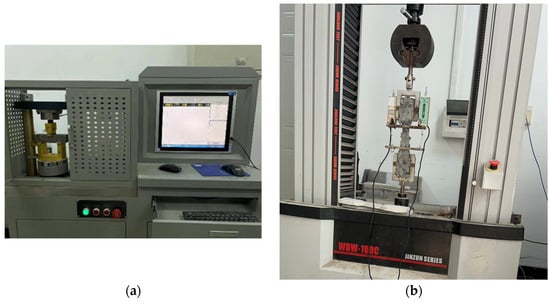
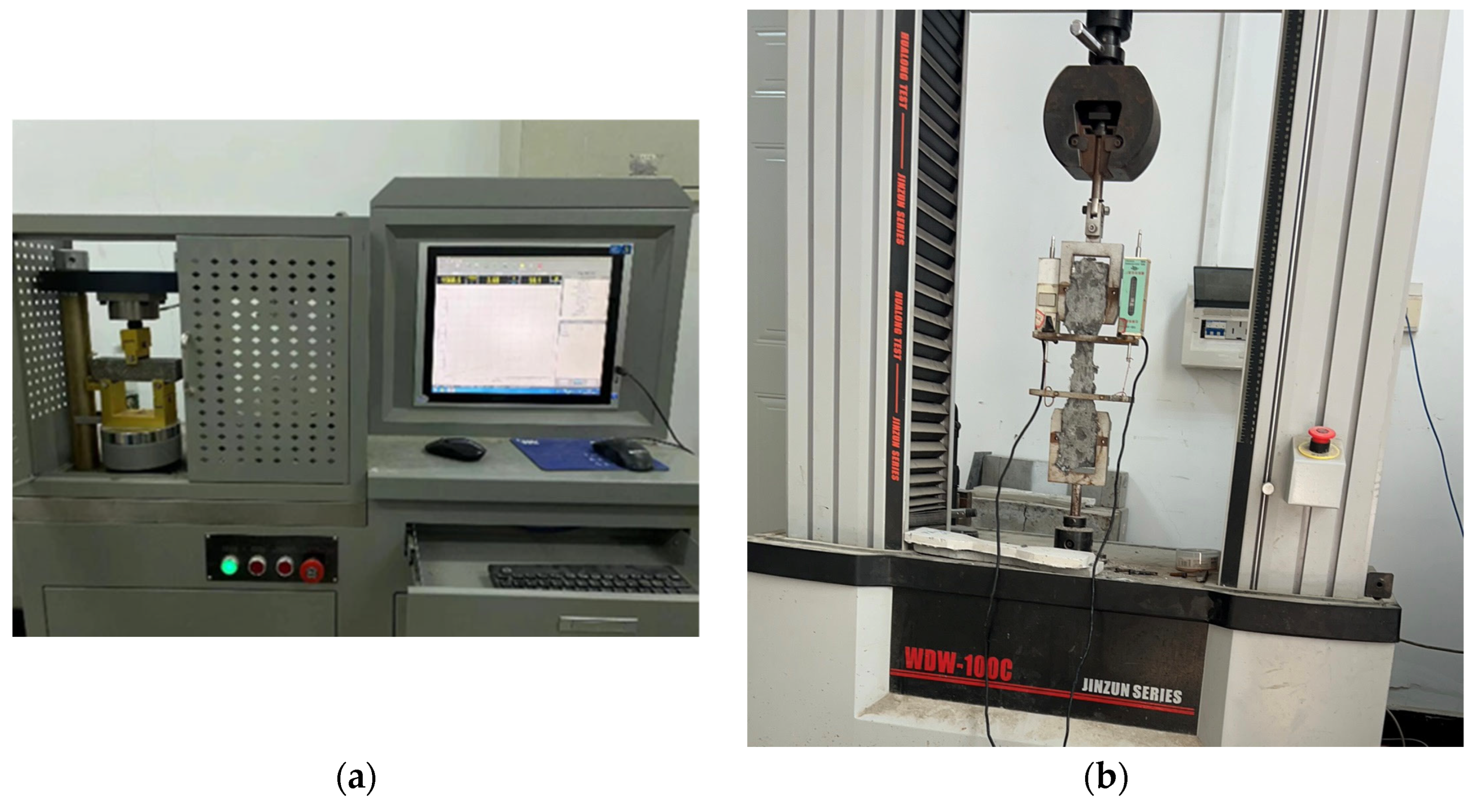
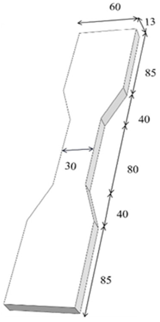
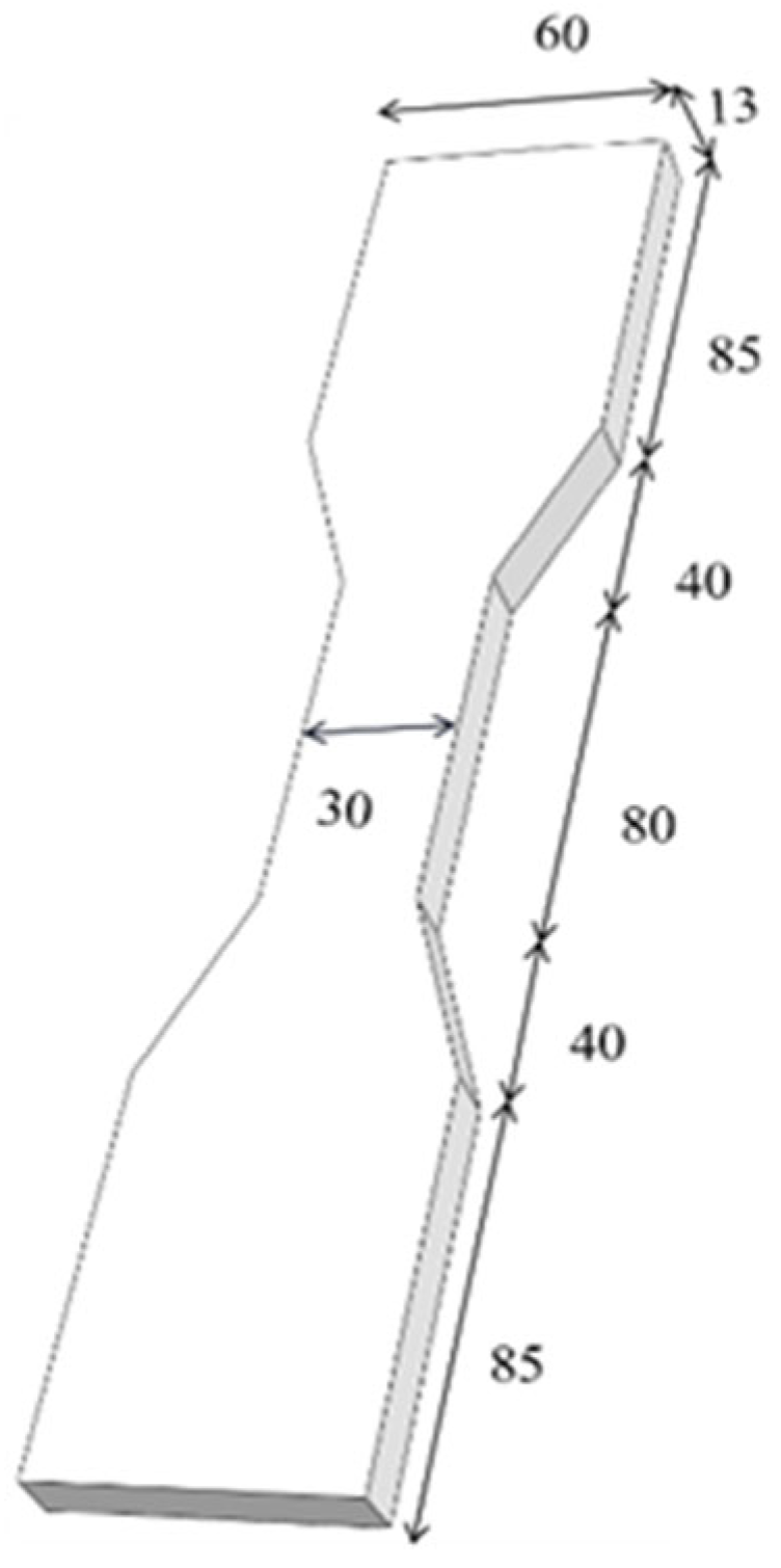
The compressive strength test was conducted using a DYE-300S microcomputer-controlled servo cement flexural and compressive testing machine (Shanghai Hualong Test Instruments Co., Ltd., Shanghai, China). Cubic specimens with dimensions of 70.7 mm × 70.7 mm × 70.7 mm were employed, and the loading rate was controlled at 1.5 kN/s. For the flexural strength test, cementitious mortar prism specimens measuring 40 mm × 40 mm × 160 mm were used. The axial tensile test was performed on a WDW-100C microcomputer-controlled electronic universal testing machine (SANS Testing Machine Co., Ltd., Shanghai, China), using dog-bone-shaped specimens with dimensions of 330 mm × 60 mm × 13 mm and a loading rate of 0.5 mm/min. The tensile testing method followed the recommendations of the Japan Society of Civil Engineers (JSCE). An extensometer with an 80 mm gauge length was attached to the side of the specimen to measure the axial tensile strain in real time. Microstructural analysis was carried out using a JSM-7610F Plus field emission scanning electron microscope (JEOL Ltd., Tokyo, Japan). The photograph of the equipment is presented in Figure 6. The dimensions of the dog-bone specimen are shown in Figure 7.
Figure 6.
(a) Loading apparatus for compression and flexural tests and (b) uniaxial tensile testing apparatus.
Figure 7.
Dog bone specimen.
3. Results and Discussion
3.1. Compressive Strength
3.1.1. Uniaxial Compression Test Behavior
The failure process of ECC cubic specimens under compression can be divided into four stages: the elastic stage, the micro-crack development stage, the macro-crack development stage, and the final failure stage. At the initial loading phase, corresponding to the elastic stage, no obvious cracks appeared on the surface of the cubic specimen, and the internal structural damage was minimal, indicating normal working conditions. As loading continued, fine cracks gradually emerged on the specimen surface and extended toward the edges and corners. Micro-damage accumulated progressively, marking the transition into the micro-crack development stage. Unlike the brittle failure typically observed in ordinary concrete during compression tests, ECC specimens exhibited pronounced ductile failure behavior under compressive loading. As the peak load approached, the specimen transitioned from the micro-crack development stage to the macro-crack development stage. During this process, the load-bearing capacity gradually decreased, and micro-cracks propagated and coalesced to form visible fine macro-cracks. The addition of steel fibers influenced the cracking morphology of hybrid fiber specimens to some extent: with increasing steel fiber content, crack distribution became finer and denser. Higher steel fiber content resulted in smaller crack widths at failure, with secondary cracks being less pronounced outside the main fracture, indicating a ductile failure mode. As deformation continued to increase without significant change in load, cracks widened progressively until the specimen entered the final failure stage, completely losing its load-bearing capacity. The ultimately failed specimen exhibited only slight bulging and oblique cracks on the surface, without spalling or the collapse of large fragments, demonstrating significantly enhanced integrity.
3.1.2. Analysis of Compressive Strength Test Results
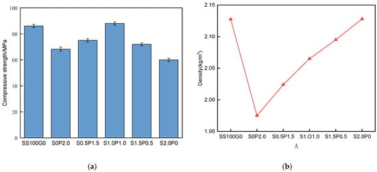
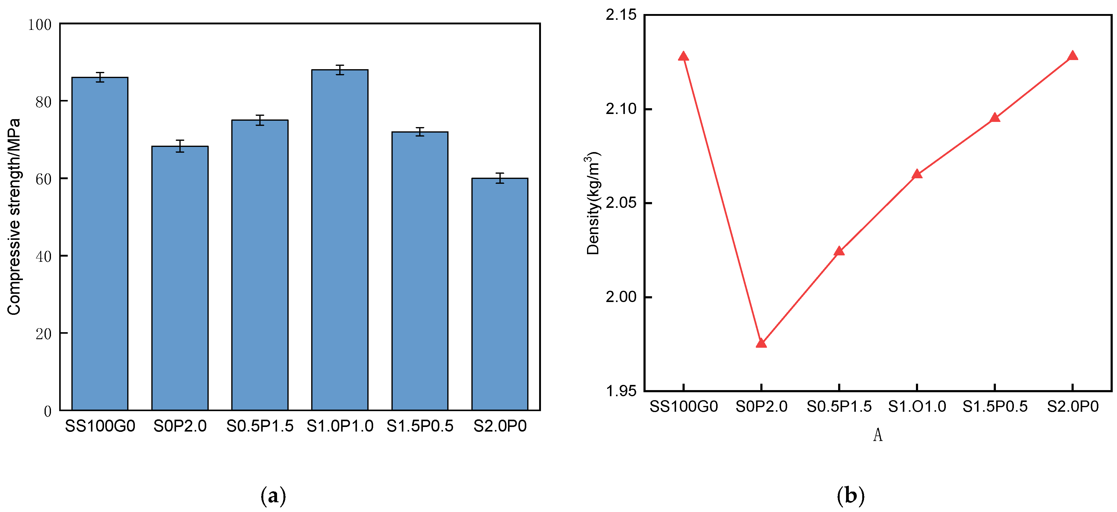
Figure 8 shows the compressive strength and density of the six mix proportions at 28 days of curing. As can be seen from Figure 8a, the compressive strength decreased by 15.2% after replacing quartz sand with geopolymer aggregate, which is primarily attributed to the lower strength of GPA compared to quartz sand. The compressive strength of the GPA-ECC initially increased and then decreased with the rising substitution rate of steel fibers for PE fibers. When steel fibers and PE fibers were hybridized (S1.0P1.0), the compressive strength of the ECC reached 88.3 MPa, which was 18.1% higher than that of the ECC reinforced solely with PE fibers (S0P2.0). This improvement is mainly due to the ability of steel fibers to promote stress redistribution within the matrix while enhancing energy absorption capacity and residual stress at cracks.
Figure 8.
(a) The 28-day compressive strength of each mix proportion specimen; (b) density of each mix proportion specimen.
However, as the steel fiber content further increases beyond 1.0% (e.g., in the S1.5P0.5 and S2.0P0 mixtures), the compressive strength begins to decline. This reduction is primarily attributed to fiber clustering and dispersion issues. An excessively high volume fraction of rigid steel fibers makes them prone to entanglement and uneven distribution during the mixing process. This “balling” effect introduces larger initial macro-defects and voids into the matrix, which significantly hinders the matrix’s ability to effectively redistribute stress around the GPA pores under compressive loading, ultimately leading to a premature decline in strength.
Additionally, the inclusion of steel fibers led to an increase in density; however, this increment was less than 5%, which can be considered negligible in practical applications.
3.2. Flexural Strength
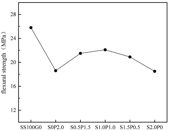
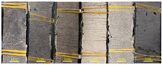
For the ECC prism specimens with 0% geopolymer aggregate content (SS100G0), where the fine aggregate consisted entirely of quartz sand, the flexural specimens exhibited fewer cracks upon failure, with a smooth and intact fracture surface. PE fibers showed both pull-out and fracture failure modes. In contrast, for the specimens with 100% geopolymer aggregate content (S0P2.0), where the fine aggregate was fully replaced by geopolymer aggregate, most cracks maintained a multi-directional propagation pattern upon flexural failure, with a reduced number of fine cracks. The fracture surface remained smooth and intact, and cracks were observed to propagate through the geopolymer aggregates at the cross-section. The failure mode of PE fibers was predominantly tensile fracture.
The incorporation of geopolymer aggregates led to a reduction in the flexural strength of the ECC. For the test groups with PE fibers only, the reinforcing effect on the ECC material was mainly manifested after the formation of initial cracks, where the flexural stress could continue to increase until reaching peak flexural strength. The matrix exhibited distinct strain-hardening and multiple cracking behavior. The addition of steel fibers primarily enhanced the flexural strength of the hybrid fiber ECC. Steel fibers effectively restrained the formation and propagation of micro-cracks, and upon failure, typically only one main crack propagated through the entire specimen. The content of steel fibers was positively correlated with the degree of crack localization. With the incorporation of steel fibers, the flexural strength of the hybrid fiber ECC showed an initial increase followed by a decreasing trend. The 28-day flexural strength of specimens with different mix proportions is shown in Figure 9.
Figure 9.
The 28-day flexural strength of specimens with different mix proportions.
3.3. Tensile Performance
3.3.1. Uniaxial Tensile Test Behavior
In uniaxial tensile testing, due to the incorporation of fibers, the ECC does not undergo immediate fracture failure under sustained uniaxial tensile loading but exhibits strain-hardening characteristics with multiple cracking. Based on the failure process observed in the uniaxial tensile tests, the tensile behavior of the ECC can be divided into three stages.
Stage 1: Linear Elastic Stage—From the initiation of loading until the first crack appears, the tensile load is primarily borne by the cementitious matrix. Stress and strain increase linearly. Due to the relatively low tensile strength of the matrix, cracks begin to form, and this stage concludes with the development of the initial crack.
Stage 2: Strain-Hardening Stage—As the load increases, the first crack forms at the weakest point. The matrix at the crack ceases to carry load, causing a drop in the load-bearing capacity. However, due to the fiber bridging effect, the propagation of the main crack slows, and the load recovers. Stress concentrates at another weak point until a second crack appears. This process repeats, with new fine cracks continuously forming on the specimen surface, exhibiting multiple cracking behavior. The stress–strain curve fluctuates upward until no further cracks develop. During crack propagation, a faint sizzling sound accompanies the pulling-out or fracture of fibers.
Stage 3: Strain-Softening Stage—With a further increase in strain, stress no longer peaks but declines gradually. No new cracks form within the gauge length, and the main crack with the weakest bridging capacity gradually widens until it penetrates completely, leading to specimen failure. Fibers are either pulled out or fractured from the matrix, accompanied by a distinct tearing sound.
3.3.2. Crack Control Capability
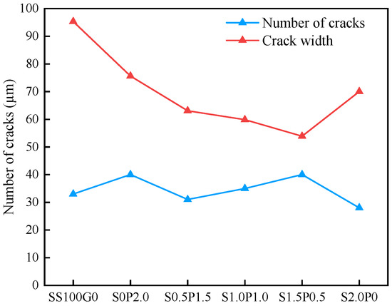
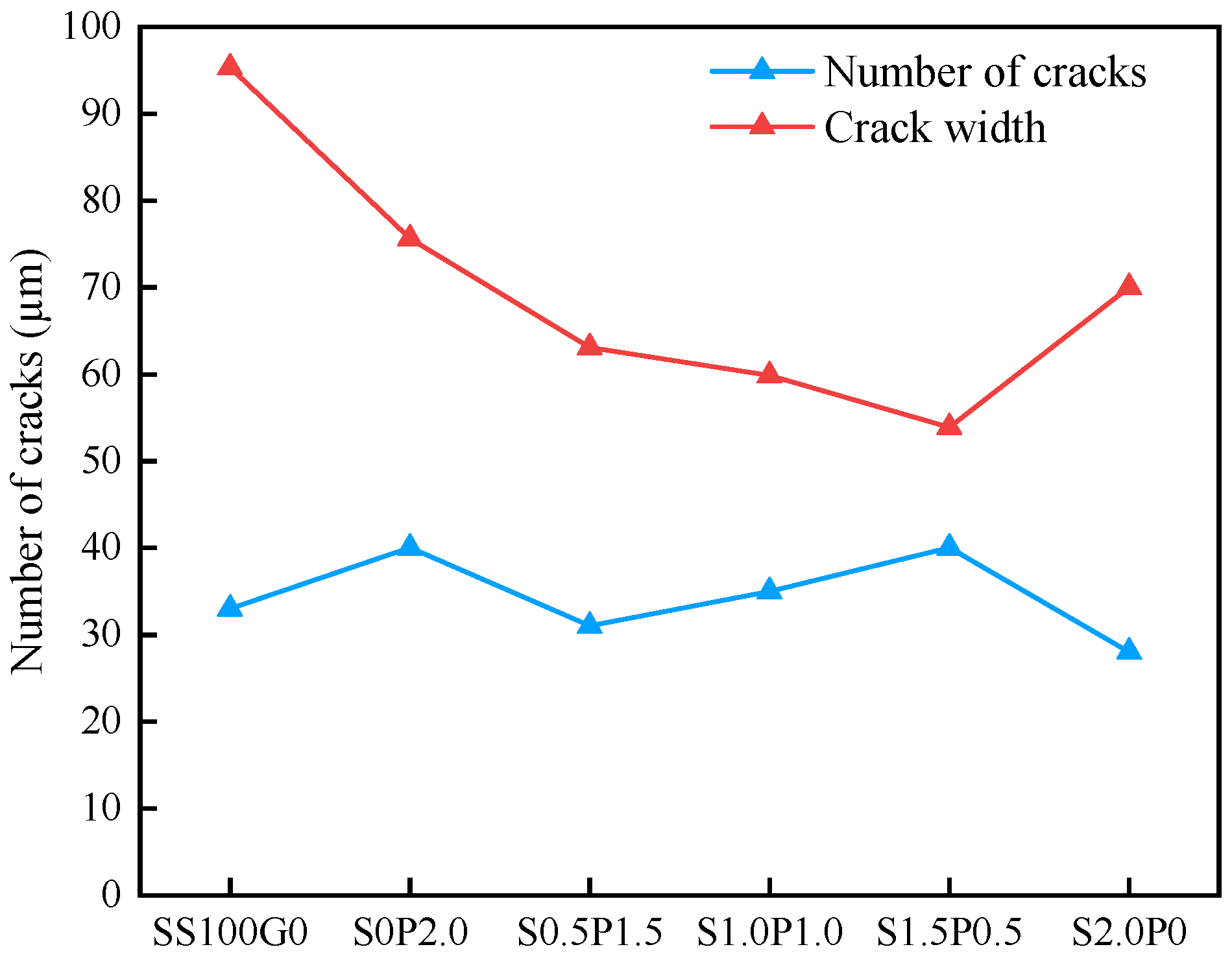
Crack width and number are critical characteristics, as they significantly influence the material’s durability. Narrow cracks can notably reduce the water permeability of ECCs, thereby enhancing the durability of the structure [28]. The cracking patterns of the ECCs are illustrated in Figure 10, and detailed crack information is summarized in Table 8. Crack widths were measured using an optical microscope with a precision of 10 μm. Figure 11 presents detailed crack width data for ECCs with different mix proportions.
Figure 10.
Crack pattern of ECC specimens.
Table 8.
Crack information of HF-ECC specimens.
Figure 11.
Crack information of ECCs with different hybrid fiber ratios.
From Table 8 and Figure 11, it can be observed that after replacing quartz sand with GPA, the average crack width of the ECC decreased by 20.6% and the number of cracks increased by 21%. This indicates that the “imperfection” effect of GPA is pronounced, effectively inducing the steady-state development of multiple cracks. When steel fibers partially replace PE fibers, the crack width further decreases, which is beneficial for improving the durability of geopolymer aggregate ECCs. Moreover, after hybridizing steel fibers, the number of cracks on geopolymer aggregate ECC specimens is reduced. However, even when only 1% of PE fibers is replaced by steel fibers, the ECC mixture still retains multiple cracking behavior. Therefore, ECCs with hybrid fibers can better control crack propagation. Nevertheless, if too many PE fibers are replaced, side effects such as non-uniform distribution and overlapping of steel fibers may occur. Consequently, the mixture S2.0P0 exhibits the smallest number of cracks and the largest average crack width.
3.3.3. Tensile Stress–Strain Curve
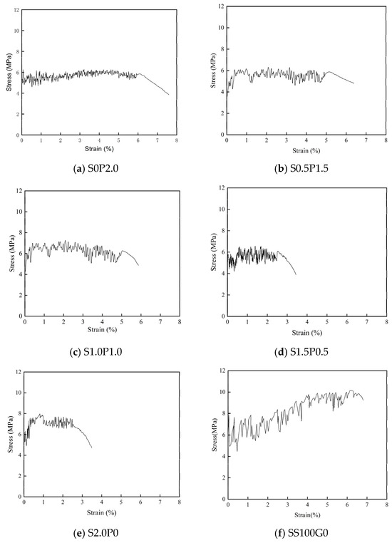
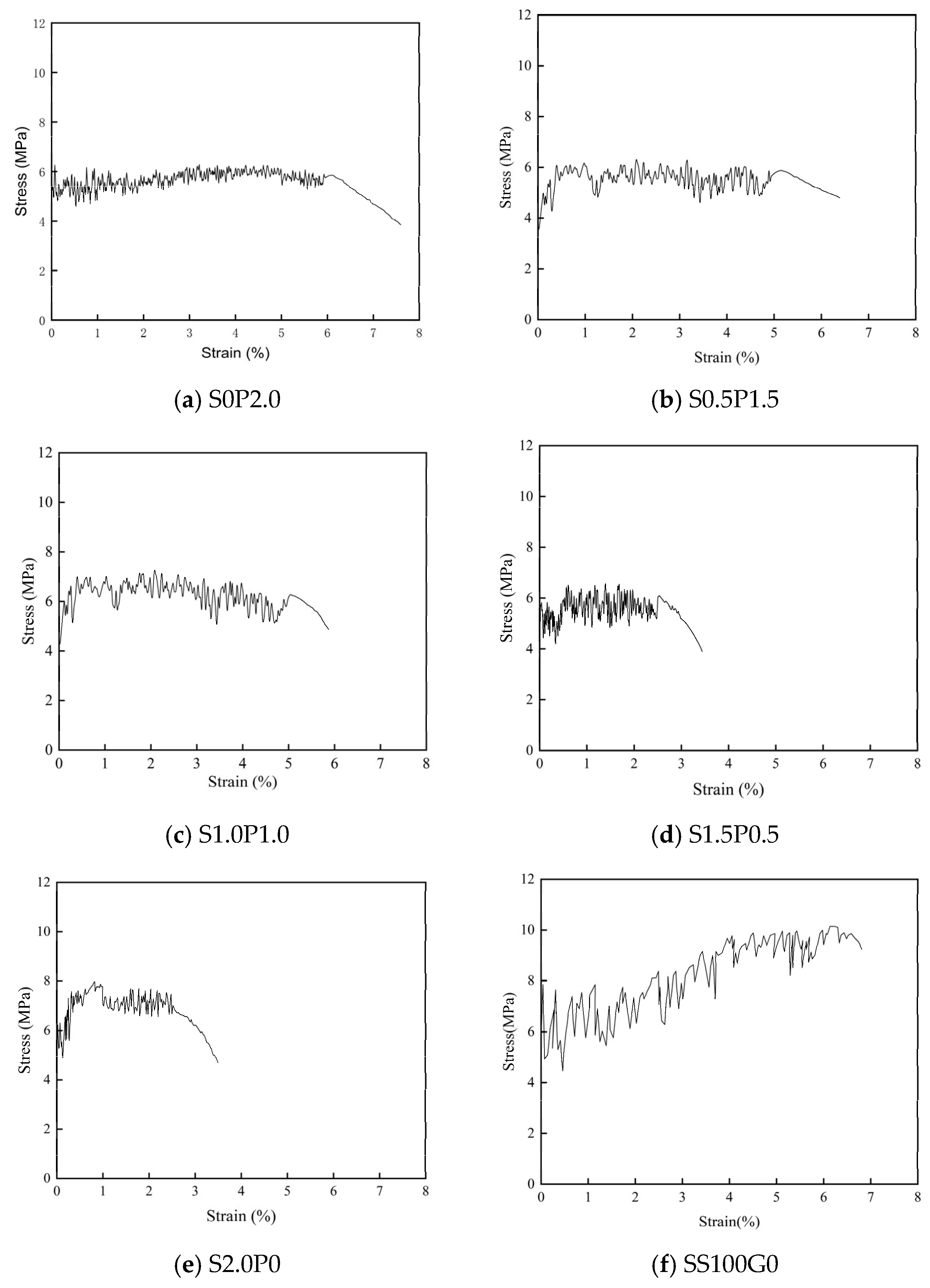
The initial cracking stress, ultimate tensile stress, and tensile strain capacity of ECCs can be determined from the tensile stress–strain relationship, as shown in Figure 12. Furthermore, the tensile modulus of ECCs can be calculated from the slope of the elastic stage of the curve. The tensile parameters of the six groups of specimens are summarized in Table 9.
Figure 12.
Stress–strain curves of each mix proportion specimen.
Table 9.
Tensile properties of each mix proportion specimen.
As can be seen from Figure 12, all ECC mixtures exhibited distinct strain-hardening behavior. The ultimate tensile stress decreased after replacing quartz sand with GPA, primarily due to the introduction of GPA, reducing the matrix toughness of the ECC. When part of the PE fibers was replaced by steel fibers, the strain capacity of the geopolymer aggregate ECC tended to decrease (see Figure 12a–e).
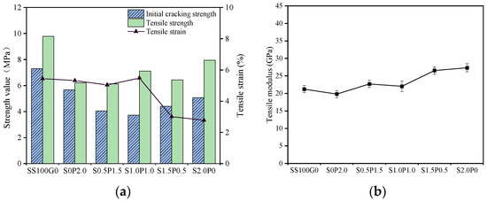
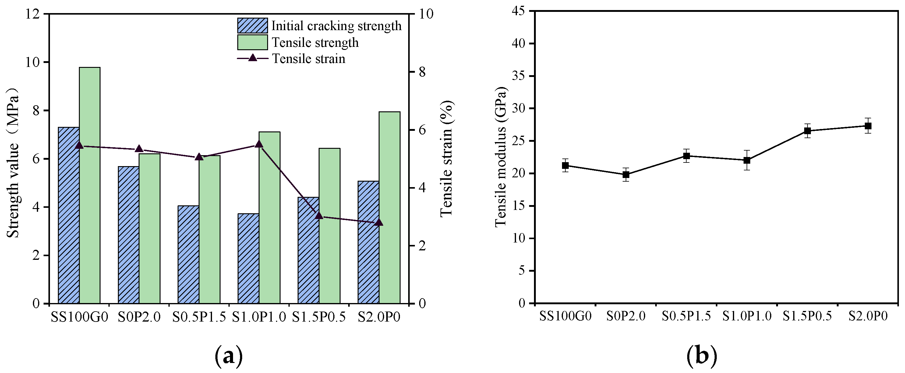
Figure 13a illustrates the tensile performance of geopolymer aggregate ECCs with different hybrid fiber ratios. As shown in Figure 13a and Table 9, the tensile strength and initial cracking strength of the geopolymer aggregate ECCs ranged from 6.20 to 7.95 MPa and 3.72 to 5.68 MPa, respectively, showing a fluctuating trend with increasing steel fiber content. On the other hand, as the steel fiber content did not exceed 1%, the strain capacities of S0P2.0, S0.5P1.5, and S1.0P1.0 were 5.32%, 5.04%, and 5.48%, respectively. Among these, the strain capacity of the geopolymer aggregate ECC was not negatively affected by the reduction in PE fiber volume. However, when 1.5% of the PE fibers was replaced by steel fibers, the strain capacity of S1.5P0.5 significantly decreased to 3.01%, whereas the strain capacities of the three geopolymer aggregate ECC groups—S0P2.0, S0.5P1.5, and S1.0P1.0—all remained around 5%. Additionally, the incorporation of steel fibers increased the elastic modulus of the ECC from 19.83 GPa for S0P2.0 to 27.34 GPa for S2.0P0, as shown in Figure 13b. The modulus of steel is approximately 220 GPa, significantly higher than that of both PE fibers and the ECC matrix, which contributes to the enhancement of the ECC’s modulus when steel fibers are added. A relatively higher modulus in concrete reflects the material’s stronger resistance to deformation after loading, which is beneficial for improving the stiffness of structural components. In summary, among the geopolymer aggregate ECCs hybridized with PE and steel fibers, S1.0P1.0 demonstrated the highest strain capacity.
Figure 13.
Tensile properties of ECC with different hybrid fiber ratios. (a) Tensile properties of specimens with different mix proportions. (b) Tensile modulus of specimens with different mix proportions.
3.4. Microscopic Morphology
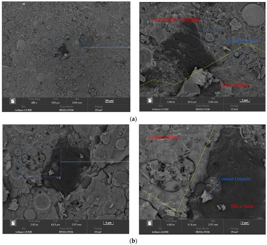
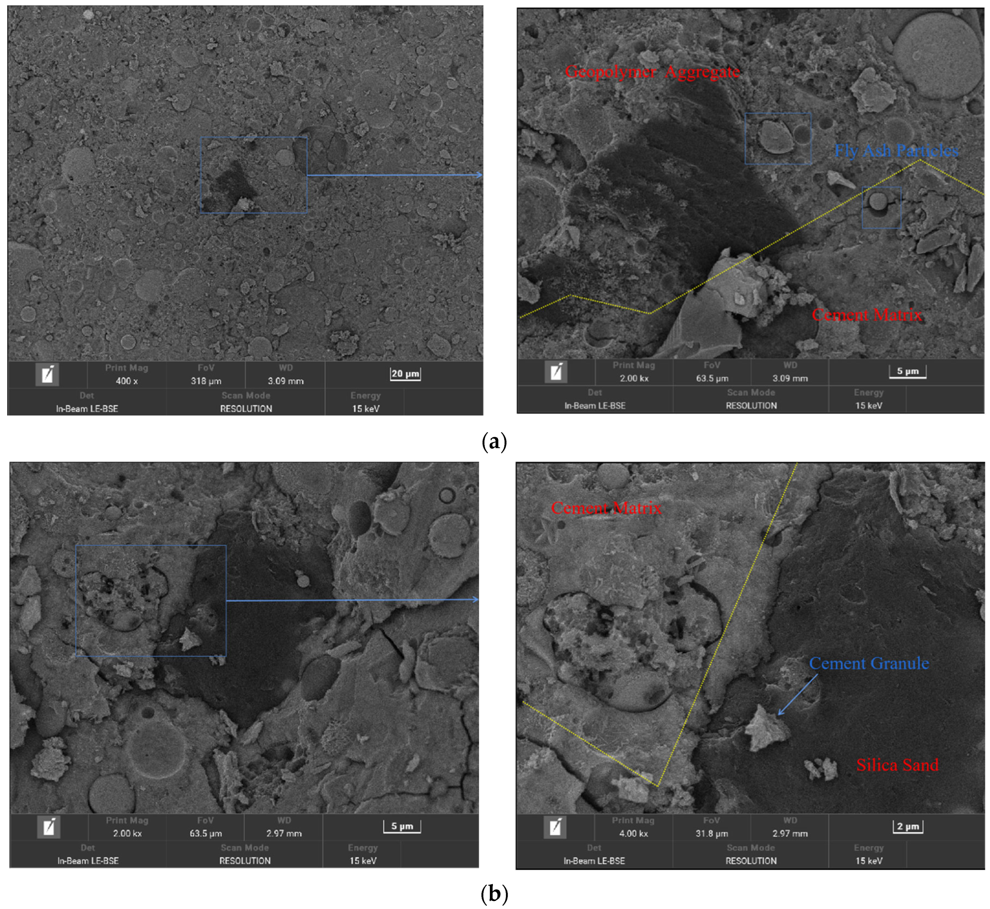
The microstructure of the interfacial regions between the geopolymer aggregate (GPA) and cement matrix, and between quartz sand and the cement matrix, are shown in Figure 14a and Figure 14b, respectively.
Figure 14.
(a) BSE images of the interfacial transition zone between the geopolymer aggregate and the cement matrix at magnifications of 400× and 2000×; (b) BSE images of the interfacial transition zone between quartz sand and the cement matrix at magnifications of 2000× and 4000×.
Unlike the relatively low reactivity of quartz sand, geopolymer aggregates can undergo chemical reactions with the cement matrix. The hydration products generated from these reactions accumulate in the interfacial transition zone between the aggregate and the matrix, resulting in a comparatively indistinct interface. Since the alkali content was maintained at 12%, the alkalinity was not excessively high, allowing the unreacted fly ash particles within the geopolymer aggregate to serve as a distinguishing feature between the aggregate and the cement matrix. In BSE (backscattered electron) observations, at a magnification of 400×, the interfacial transition zone between the geopolymer aggregate and the cement matrix was difficult to distinguish. When the magnification was increased to 2000×, the interfacial transition zone became clearly visible. The surface of the geopolymer aggregate exhibited numerous honeycomb-like pores. Notably, with a high 24 h water absorption capacity of 24.6%, the porous GPA effectively acts as an internal curing agent within the ECC matrix. During the pre-wetting process and mixing, these pores absorb and retain a significant amount of water. As the hydration of the surrounding cementitious matrix progresses and the internal relative humidity drops, the GPA slowly releases this stored moisture. This internal curing mechanism promotes continuous secondary hydration reactions and mitigates autogenous shrinkage, thereby further densifying the interfacial transition zone (ITZ) and accelerating strength development. A gel-like reaction zone was observed in the interfacial transition zone between the geopolymer aggregate and the cement matrix, likely consisting of pozzolanic products formed by the secondary reaction between partially dissolved fly ash particles and calcium hydroxide from the cement.
In contrast, quartz sand exhibits poor reactivity with cement and is simply enveloped by the cement paste, leading to a clearly discernible boundary. In BSE observations at 2000× magnification, the interfacial transition zone between quartz sand and the cement matrix was very distinct, and the crack gaps in this region were larger than those observed at the same magnification between the geopolymer aggregate and cement matrix. Due to ion exchange between siliceous aggregates such as quartz sand and the cement pore solution [29], even when the magnification was increased to 4000×, no gel-like reaction zone was observed between the quartz sand and the cement matrix. Furthermore, numerous micro-cracks were present around the quartz sand aggregate, likely resulting from the relatively weak bond strength between the quartz sand and the cement matrix.
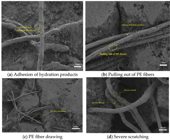
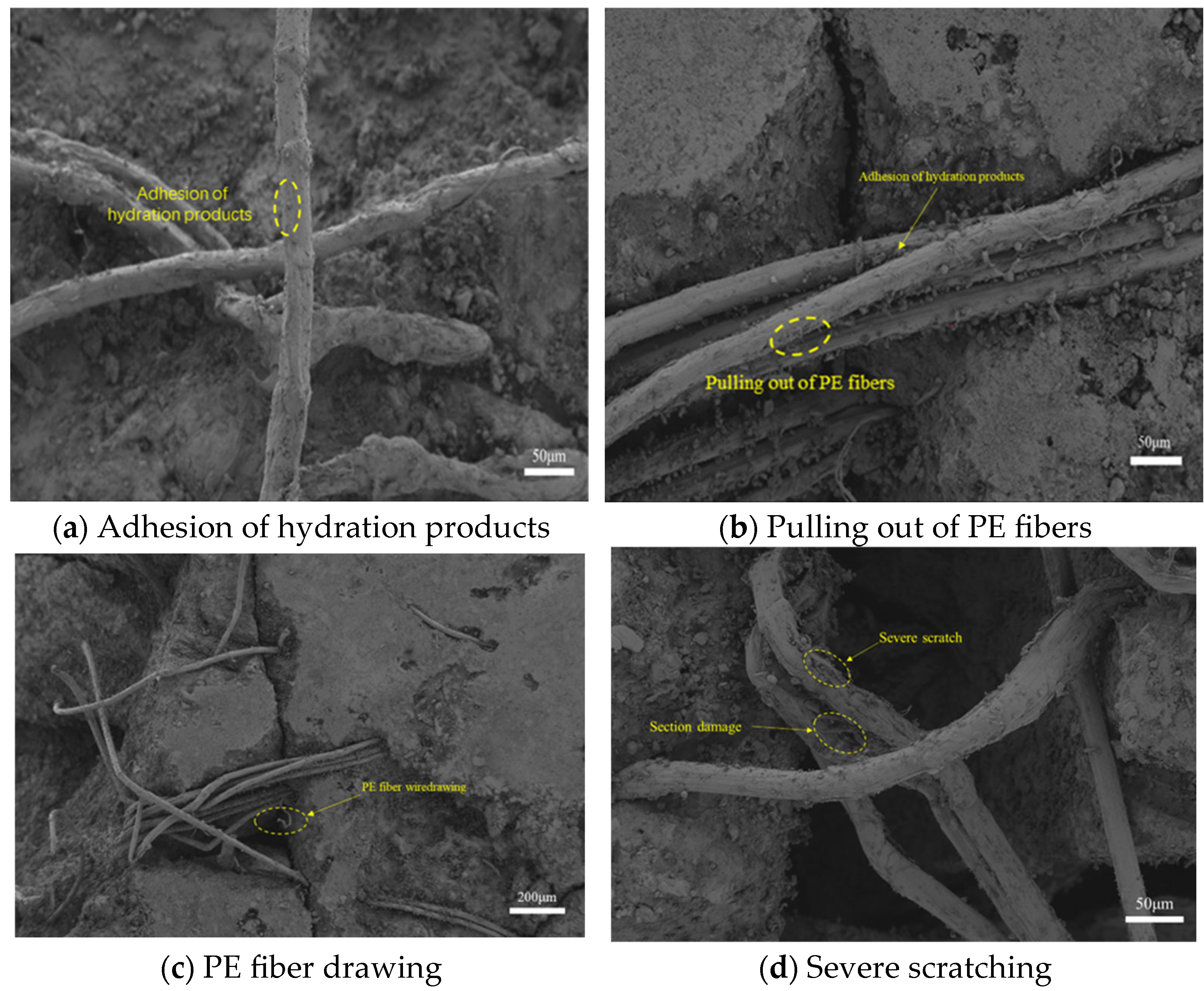
The SEM image in Figure 15a reveals that steel fibers exhibited only pull-out from the matrix, whereas PE fibers showed both pull-out and surface delamination. Figure 15a,b indicate that both steel and PE fibers were covered with hydration products, implying strong fiber/matrix interfacial bonding. Figure 15c,d illustrate the surface morphology of PE fibers after being scratched by the matrix during pull-out. The dense microstructure of the hardened matrix, along with the high-strength mixture, generally leads to strong fiber/matrix interfacial bonding. Under such conditions, due to the relatively higher stiffness of steel fibers compared to the matrix, small matrix fragments are often observed adhering to the steel fibers after pull-out. In contrast, polymer-based fibers typically possess lower stiffness; therefore, in addition to adhering fragments, surface scratches can also be found on these fibers.
Figure 15.
SEM images of fibers.
Further observation of the fiber pull-out morphology and the interfacial transition zone (ITZ) reveals the underlying micromechanical synergy of the GPA-ECC system. Rather than acting merely as weak points, the porous structure of the geopolymer aggregates (GPAs) effectively functions as “microscopic artificial defects.” These distributed defects locally reduce the crack-initiation toughness of the matrix, thereby guiding the stress to trigger steady-state multiple cracking instead of catastrophic localized failure. Moreover, the SEM images demonstrate a distinct cross-scale bridging mechanism facilitated by the hybrid fibers. The highly flexible PE fibers are observed to undergo extensive fibrillation and frictional pull-out, which dissipates a significant amount of fracture energy at the micro-crack level. Simultaneously, the rigid steel fibers exhibit strong mechanical anchorage and tight matrix adhesion within the ITZ, providing robust resistance against macro-crack widening. This synergistic “defect-induction and cross-scale fiber bridging” mechanism fundamentally explains the excellent macroscopic ductility and strain-hardening behavior of the hybrid composites (e.g., S1.0P1.0).
4. Sustainability Assessment of Materials
The economic and environmental impacts of ECCs were evaluated using the MSI, encompassing material costs and carbon footprint. The carbon footprint includes all CO2 emissions associated with material production, covering stages such as extraction, processing, and fuel combustion. Table 10 summarizes the MSI values of the raw materials for ECCs. Given that geopolymer aggregates are largely stockpiled and not reasonably reused, their price as solid waste is typically extremely low and can be considered negligible, while their CO2 emissions and energy consumption are assumed to be zero. It should be explicitly noted that treating the intrinsic material cost and CO2 emissions of the geopolymer aggregate as zero is based on the assumption that it is utilized directly as an industrial solid waste. This calculation boundary does not account for potential additional industrial-scale post-processing energy consumption, beyond the lab-scale activation and crushing procedures already quantified in this study.
Table 10.
Cost and CO2 emission of ECC components.
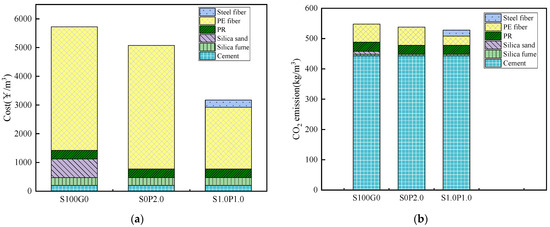
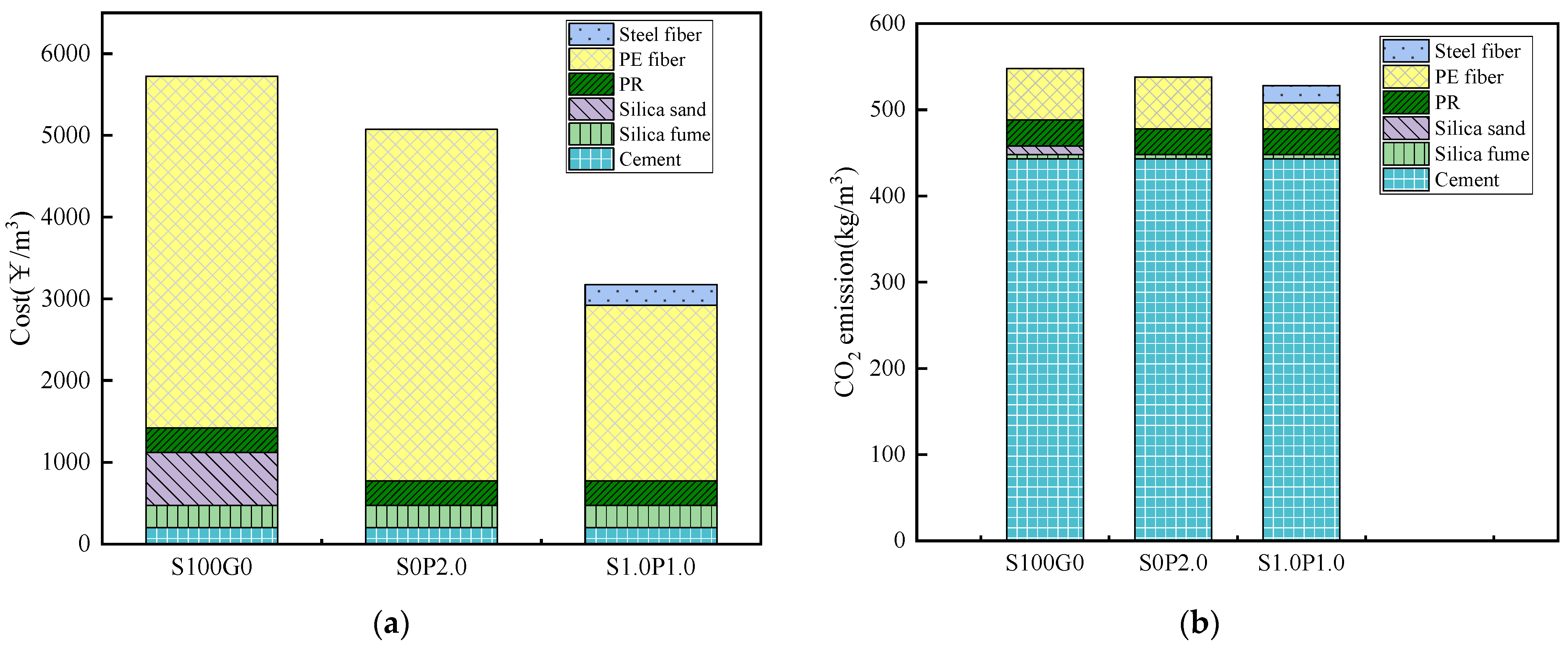
Figure 16 analyzes and quantifies the cost and total carbon footprint (Mtotal) of the three ECC types, with the specific calculation formula being as follows:
Mtotal = ∑Mi × Fi
Figure 16.
Comparison of MSI for SS100G0, S0P2.0 and S1.0P1.0: (a) cost; (b) CO2 emissions.
Mi represents the unit mass CO2 emission or price of the i-th raw material in the ECC, as detailed in Table 10; Fi denotes the consumption amount of the i-th raw material.
Although six different mix proportions were investigated in the mechanical tests, the S1.0P1.0 mixture was selected as the representative hybrid group for the comprehensive sustainability comparison in Figure 16. This selection logic is primarily because the S1.0P1.0 group exhibited the optimal balance of mechanical performance, achieving the highest compressive strength (88.3 MPa) while maintaining an excellent ultimate tensile strain (5.48%) among all the tested hybrid formulations.
Figure 16a compares the costs of SS100G0, S0P2.0, and S1.0P1.0. The cost of SS100G0 is 5732 RMB/m3, while the geopolymer aggregate ECC (S0P2.0) and the hybrid fiber geopolymer aggregate ECC (S1.0P1.0) exhibit lower costs. It is evident from the figure that PE fiber is the most expensive component in the ECC. Despite its small volume fraction, PE fiber accounts for more than 75% of the total cost. S0P2.0 demonstrates a lower cost than SS100G0. By incorporating lower-cost steel fibers, S1.0P1.0 further reduces the cost from 5344 RMB/m3 to 3182 RMB/m3.
Figure 16b presents the CO2 emissions of different ECC mixtures. The CO2 emissions of SS100G0 are as high as 547kg/m3, equivalent to 160% of that of conventional concrete. In contrast, S1.0P1.0 exhibits significantly better environmental performance, with CO2 emissions of 520 kg/m3, representing a 5% reduction. Cement is the primary contributor to CO2 emissions in ECCs, accounting for 84% of the total emissions.
To provide a more comprehensive evaluation of the material’s cost-effectiveness and environmental benefits, a performance–cost–carbon comparison was conducted. Two comprehensive sustainability indicators were introduced: the cost per unit compressive strength (RMB/m3·MPa) and the CO2 emission per unit tensile strain capacity (kg/m3·%). By normalizing the economic and environmental burdens against the actual mechanical performance, a clearer assessment of the material’s overall efficiency is achieved. Specifically, the hybrid fiber geopolymer aggregate ECC (S1.0P1.0) achieves a highly competitive cost per unit compressive strength due to its significantly reduced unit cost (3182 RMB/m3) coupled with its robust compressive strength (88.3 MPa). Similarly, regarding the environmental impact, S1.0P1.0 demonstrates an exceptionally low CO2 emission per unit tensile strain, indicating that it generates substantially fewer carbon emissions to achieve its outstanding ductility (5.48%). This comprehensive analysis strongly verifies that the S1.0P1.0 mixture is not merely cheaper and greener in absolute terms, but is also highly cost-effective and low-carbon from a performance-driven perspective, thereby highlighting its immense potential for sustainable engineering applications.
5. Conclusions
This study successfully developed an economical and environmentally friendly engineered cementitious composite (ECC) by utilizing geopolymer as a replacement aggregate and hybridizing steel fibers with PE fibers. The main conclusions are summarized as follows:
- (1)
- The incorporation of geopolymer aggregates led to a reduction in both the compressive and flexural strengths of the ECC. On the other hand, the addition of steel fibers at a 1% volume fraction tended to enhance the compressive and flexural strengths of the ECC. The compressive strength of the developed ECC exceeded 80 MPa, meeting the lower threshold for high-strength concrete (concrete with compressive strength greater than C50).
- (2)
- When steel fibers partially replaced PE fibers, with a steel fiber volume fraction within 1%, the tensile strength and strain capacity of the ECC mixture were comparable to those of an ECC containing only PE fibers. However, when 1.5% steel fibers were incorporated, the strain capacity significantly decreased (from 5.48% to 3.01%). Furthermore, the tensile modulus of the ECC mixture increased with higher steel fiber content.
- (3)
- The MSI analysis demonstrated that the designed ECC, which uses geopolymer as aggregate and hybridizes steel and PE fibers, effectively reduces both cost and CO2 emissions compared to conventional ECCs. This contributes to the low-carbon development of concrete materials.
Author Contributions
Conceptualization, J.Z. and Y.Z.; methodology, Y.Z.; software, J.Z. and Y.Z.; validation, J.Z. and Y.Z.; writing—original draft preparation, J.Z. and Y.Z.; writing—review and editing, Y.Z.; visualization, J.Z.; supervision, J.Z. All authors have read and agreed to the published version of the manuscript.
Funding
This research received no external funding.
Data Availability Statement
Data are contained within the article.
Conflicts of Interest
The authors declare no conflicts of interest.
References
- Xu, L.-Y.; Zhang, Z.-H.; Li, Z.-J.; Wang, Y.-C. Tensile over-saturated cracking of ultra-high-strength engineered cementitious composites (UHS-ECC) with artificial geopolymer aggregates. Cem. Concr. Compos. 2023, 136, 104896. [Google Scholar] [CrossRef] [Scilit]
- Xu, L.-Y.; Li, Z.-J.; Zhang, Z.-H.; Wang, Y.-C. Tailoring strain-hardening behavior of high-strength Engineered Cementitious Composites (ECC) using hybrid silica sand and artificial geopolymer aggregates. Mater. Des. 2022, 220, 110876. [Google Scholar] [CrossRef] [Scilit]
- Li, S.; Chan, T.-M.; Young, B. Experimental investigation on axial compressive behavior of novel FRP-ECC-HSC composite short column. Compos. Struct. 2023, 303, 116285. [Google Scholar] [CrossRef] [Scilit]
- Al Biajawi, M.I.; Ismail, M.; Alomayri, T.; Alrshoudi, F. Recycled coal bottom ash as sustainable materials for cement replacement in cementitious Composites: A review. Constr. Build. Mater. 2022, 338, 127624. [Google Scholar] [CrossRef] [Scilit]
- Xie, C.P.; Liu, J.; Yu, J.; Leung, C.K.Y. Review on different testing methods and factors affecting fracture properties of fiber reinforced cementitious composites. Constr. Build. Mater. 2021, 273, 121766. [Google Scholar] [CrossRef] [Scilit]
- Chen, Y.X.; Yu, J.; Leung, C.K.Y. Use of high strength strain-hardening cementitious composites for flexural repair of concrete structures with significant steel corrosion. Constr. Build. Mater. 2018, 167, 325–337. [Google Scholar] [CrossRef] [Scilit]
- Huang, B.-T.; Yu, J.; Leung, C.K.Y. Seawater sea-sand Engineered Cementitious Composites (SS-ECC) for marine and coastal applications. Compos. Commun. 2020, 20, 100353. [Google Scholar] [CrossRef] [Scilit]
- Huang, B.-T.; Yu, J.; Leung, C.K.Y. Engineered/strain-hardening cementitious composites (ECC/SHCC) with an ultra-high compressive strength over 210 MPa. Compos. Commun. 2021, 26, 100775. [Google Scholar] [CrossRef] [Scilit]
- Lai, B.L.; Zhou, X.; Zhang, M.Y.; Zheng, X.F.; Fang, S.G. Experimental study on the eccentric compressive behavior of steel reinforced concrete composite columns with stay-in-place ECC jacket. J. Build. Eng. 2025, 102, 112007. [Google Scholar] [CrossRef] [Scilit]
- Lai, B.L.; Zhang, M.Y.; Zheng, X.F.; Chen, Z.P.; Zheng, Y.Y. Experimental study on the axial compressive behaviour of steel reinforced concrete composite columns with stay-in-place ECC jacket. J. Build. Eng. 2023, 68, 106174. [Google Scholar] [CrossRef] [Scilit]
- Lai, B.L.; Zheng, X.F.; Zhang, Y.X.; Zhang, M.Y.; Zhu, L.; Fan, S.G. Structural behavior of steel reinforced concrete composite columns with ECC permanent formwork: Numerical simulation and parametric study. Structures 2025, 80, 109868. [Google Scholar] [CrossRef] [Scilit]
- Mesgari, S.; Akbarnezhad, A.; Xiao, J.Z. Recycled geopolymer aggregates as coarse aggregates for Portland cement concrete and geopolymer concrete: Effects on mechanical properties. Constr. Build. Mater. 2020, 236, 117571. [Google Scholar] [CrossRef] [Scilit]
- Xu, L.-Y.; Zhang, Z.-H.; Li, Z.-J.; Wang, Y.-C. Enhancing long-term tensile performance of Engineered Cementitious Composites (ECC) using sustainable artificial geopolymer aggregates. Cem. Concr. Compos. 2022, 133, 104676. [Google Scholar] [CrossRef] [Scilit]
- Xu, L.-Y.; Li, Z.-J.; Zhang, Z.-H.; Wang, Y.-C. High-strength high-ductility Engineered/Strain-Hardening Cementitious Composites (ECC/SHCC) incorporating geopolymer fine aggregates. Cem. Concr. Compos. 2022, 125, 104296. [Google Scholar] [CrossRef] [Scilit]
- Mohammed, B.S.; Khed, V.C.; Liew, M.S. Optimization of hybrid fibres in engineered cementitious composites. Constr. Build. Mater. 2018, 190, 24–37. [Google Scholar] [CrossRef] [Scilit]
- Pakravan, H.R.; Jamshidi, M.; Latifi, M. Study on fiber hybridization effect of engineered cementitious composites with low-and high-modulus polymeric fibers. Constr. Build. Mater. 2016, 112, 739–746. [Google Scholar] [CrossRef] [Scilit]
- Ahmed, S.F.U.; Maalej, M. Tensile strain hardening behaviour of hybrid steel-polyethylene fibre reinforced cementitious composites. Constr. Build. Mater. 2009, 23, 96–106. [Google Scholar] [CrossRef] [Scilit]
- Tinoco, M.P.; Silva, F.d.A. On the mechanical behavior of hybrid fiber reinforced strain hardening cementitious composites subjected to monotonic and cyclic loading. J. Mater. Res. Technol. 2021, 11, 754–768. [Google Scholar] [CrossRef] [Scilit]
- Yao, W.; Li, J.; Wu, K. Mechanical properties of hybrid fiber-reinforced concrete at low fiber volume fraction. Cem. Concr. Res. 2003, 33, 27–30. [Google Scholar] [CrossRef] [Scilit]
- Mao, W.-H.; Liu, J.-P.; Ding, Y. High-modulus and low-shrinkage hybrid-fiber reinforced engineered cementitious composites (ECC). Mater. Struct. 2022, 55, 87. [Google Scholar] [CrossRef] [Scilit]
- Xu, L.-Y.; Li, Z.-J.; Zhang, Z.-H.; Wang, Y.-C. Development of artificial one-part geopolymer lightweight aggregates by crushing technique. J. Clean. Prod. 2021, 315, 128200. [Google Scholar] [CrossRef] [Scilit]
- Shilar, F.A.; Ranjbar, N.; Allahverdi, A.; Khorami, M. Preparation and validation of sustainable metakaolin based geopolymer concrete for structural application. Constr. Build. Mater. 2023, 371, 130688. [Google Scholar] [CrossRef] [Scilit]
- Samantasinghar, S.; Singh, S.P. Effect of synthesis parameters on compressive strength of fly ash-slag blended geopolymer. Constr. Build. Mater. 2018, 170, 225–234. [Google Scholar] [CrossRef] [Scilit]
- Yu, J.; Wu, H.-L.; Leung, C.K.Y. Feasibility of using ultrahigh-volume limestone-calcined clay blend to develop sustainable medium-strength Engineered Cementitious Composites (ECC). J. Clean. Prod. 2020, 262, 121343. [Google Scholar] [CrossRef] [Scilit]
- Hammond, G.P.; Jones, C.I. Embodied energy and carbon in construction materials. Proc. Inst. Civ. Eng. -Energy 2008, 161, 87–98. [Google Scholar] [CrossRef] [Scilit]
- Ma, C.; Zhang, Y.; Liu, J.; Wang, Q. Preparation of cleaner one-part geopolymer by investigating different types of commercial sodium metasilicate in China. J. Clean. Prod. 2018, 201, 636–647. [Google Scholar] [CrossRef] [Scilit]
- Ma, C.; Zhao, B.; Guo, S.; Long, G.; Xie, Y. Properties and characterization of green one-part geopolymer activated by composite activators. J. Clean. Prod. 2019, 220, 188–199. [Google Scholar] [CrossRef] [Scilit]
- Paul, S.C.; van Zijl, G.P.A.G. Crack formation and chloride induced corrosion in reinforced strain hardening cement-based composite (R/SHCC). J. Adv. Concr. Technol. 2014, 12, 340–351. [Google Scholar] [CrossRef] [Scilit]
- Tasong, W.A.; Cripps, J.C.; Lynsdale, C.J. Aggregate-cement chemical interactions. Cem. Concr. Res. 1998, 28, 1037–1048. [Google Scholar] [CrossRef] [Scilit]

Disclaimer/Publisher’s Note: The statements, opinions and data contained in all publications are solely those of the individual author(s) and contributor(s) and not of MDPI and/or the editor(s). MDPI and/or the editor(s) disclaim responsibility for any injury to people or property resulting from any ideas, methods, instructions or products referred to in the content. |
© 2026 by the authors. Licensee MDPI, Basel, Switzerland. This article is an open access article distributed under the terms and conditions of the Creative Commons Attribution (CC BY) license.