


Abstract
Free-form concrete panels (FCPs) require precise lower-shape implementation because lower-shape errors directly affect thickness quality, geometric accuracy, and constructability. Although previous studies have developed several lower-mold systems, the sectional behavior of lower-shape errors and their deformation tendencies under concrete load have not been sufficiently clarified. Therefore, this study investigates the sectional shape error characteristics of the lower silicone mold (LSM) before casting and of the lower shape of the FCP after casting under combined curvature and thickness conditions. Single-curved FCPs were designed with curvatures of 20, 25, and 30 mm and thicknesses of 20, 30, and 40 mm. The lower geometry was divided into middle and edge sections, and statistical analyses were conducted to examine curvature-dependent deformation and load-induced error behavior. Before casting, the mean error of the LSM increased from 0.289 mm to 0.345 mm and 0.425 mm as curvature increased. After casting, the lower-shape error of the manufactured FCPs ranged from 0.313 mm to 0.444 mm. Under the 30 mm curvature and 20 mm thickness condition, the error decreased after casting, indicating partial load compensation, whereas manufacture was not possible under the 30 mm curvature and 40 mm thickness condition because of excessive side-mold displacement. These results provide quantitative evidence for deformation behavior under load and support the need for FCP-specific quality criteria.
1. Introduction
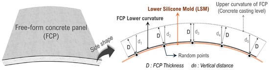
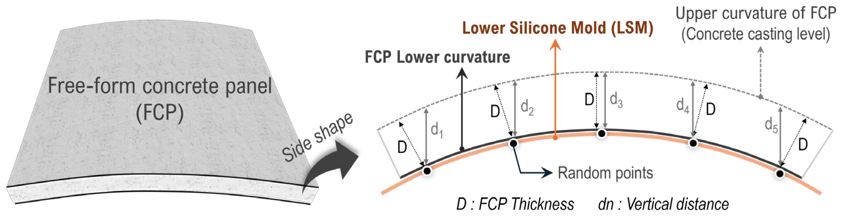
Shape errors inevitably occur in the lower shape of free-form concrete panels (FCPs). Since the lower shape error, along with the upper shape error, determines the thickness of the FCP, it directly affects production quality. Because FCPs are used to implement curved free-form geometries in non-standard architectural applications, their thickness is defined and measured differently from that of conventional flat panels [1,2,3,4,5]. As shown in Figure 1, when the side geometry of an FCP is examined, the distance between the lower curved surface and the upper curved surface of the FCP, which corresponds to the concrete casting level, defines the thickness of the panel. This distance is denoted as D in Figure 1. Specifically, D represents the length of the normal line drawn perpendicularly from random points on the lower curved surface of the FCP to the upper surface [1]. In contrast, the vertical distance value dn is the thickness criterion used for flat panels. Since flat panels do not have curved surfaces, their production process is relatively simple and it is easier to satisfy quality standards [1]. However, in the case of FCPs, a consistent thickness must be secured throughout all sections, which requires highly advanced production technology [1,6]. If the thickness quality of an FCP is degraded, not only is it difficult to perfectly realize the aesthetic appearance of free-form architecture, but inconsistent thickness can also cause construction errors during the side-to-side connection of adjacent FCPs in the installation process [7]. To secure the thickness quality of FCPs, it is particularly important to first ensure the precision of the lower shape rather than that of the upper shape. A representative mold used to implement the lower shape of FCPs is the lower silicone mold (LSM), as shown in Figure 1. After the shape of the LSM is implemented with sufficient precision, the upper shape can then be formed through concrete casting.
Figure 1.
Definition of FCP Thickness.
Previous studies have made various efforts to develop technologies for implementing the lower shape of FCPs. Early studies explored flexible mold systems composed of height-adjustable pin arrays and elastic rubber sheets [8,9,10]. In these systems, vertical displacement of individual pins deforms an overlying elastic membrane to form a curved casting surface. In these studies, double-curved FCPs with a thickness of 50 mm were manufactured; however, the thickness error was found to be as large as approximately ±5 mm [9]. In addition, the magnitudes of the errors appearing in the lower and upper shapes of the mold and the panel, both before and after casting, were not analyzed in detail. Another approach involved inflatable or air-supported silicone mold systems, in which air pressure is used to generate the curved geometry prior to casting [11]. However, the shape precision of this system is low, and it appears to be more suitable for the production of free-form sculptures rather than panels. Moreover, the thickness of the trial-produced panel was only 10 mm, which is far too thin to be used as a free-form exterior panel and therefore cannot reasonably be regarded as an FCP.
Next, a technology for producing free-form panels using reusable wax molds was developed [12]. In this method, wax is melted and formed into a free-form mold, and after panel production, the wax is melted again for reuse. However, the repeated processes of melting and solidifying wax for every FCP production cycle require substantial time and cost. In addition, although free-form shapes were physically realized in that study, no original design geometry was presented as a reference, and no comparative analysis of shape errors was conducted. Therefore, it is difficult to produce high-quality FCPs using this technology.
Subsequent research introduced computer numerical control (CNC)-based lower mold control systems, in which a silicone sheet mounted on vertically movable rods is shaped by adjusting rod heights according to calculated coordinates [13]. In this configuration, the silicone sheet was fixed to the rods using bolt connections, which can induce localized deformation around connection points and affect sectional uniformity. In FCPs manufactured using this technology, bolt marks remained on the lower surface at the locations where the rods and LSM were connected, which caused aesthetic problems and also contributed to an increase in shape error.
To address connection-related deformation issues, Yun proposed a detachable support mechanism using a silicone-cap interface between rods and the LSM [13,14]. This system eliminates rigid bolt fixation and enables more uniform elastic deformation across the mold surface. The present study adopts this silicone-cap-based lower mold control technology as the experimental platform. Through this technology, the precision of the lower shape of the FCP was improved compared with the conventional bolted connection method, while also making it possible to secure a smooth lower surface free from bolt marks, cracks, and similar defects.
In addition, other technologies have been developed, such as the fabrication of free-form EPS molds using 3D printing and the fabrication of free-form molds through the processing of wood or steel plates [15,16]. However, these methods have the following limitations. In the case of EPS mold fabrication, the production process requires considerable time, the EPS mold cannot be reused, and construction waste is generated. Moreover, marks from the EPS remain on the produced free-form surface, requiring additional plastering work. Likewise, technologies based on processing wood or steel plates also rely on non-reusable molds and involve high costs and long production times [15].
As discussed above, among the technologies studied to date, the FCP production technology based on Yun’s detachable support system using silicone caps and an LSM is regarded as the most practical and promising approach for implementing reusable and smooth free-form panel production. However, when this technology is applied, a limitation still remains in that different error patterns appear in different sections of the LSM, and this can be understood by examining the FCP manufacturing process.
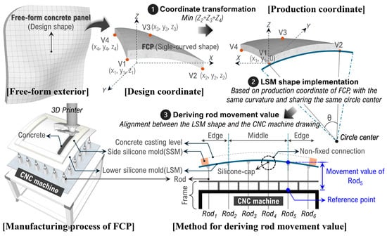
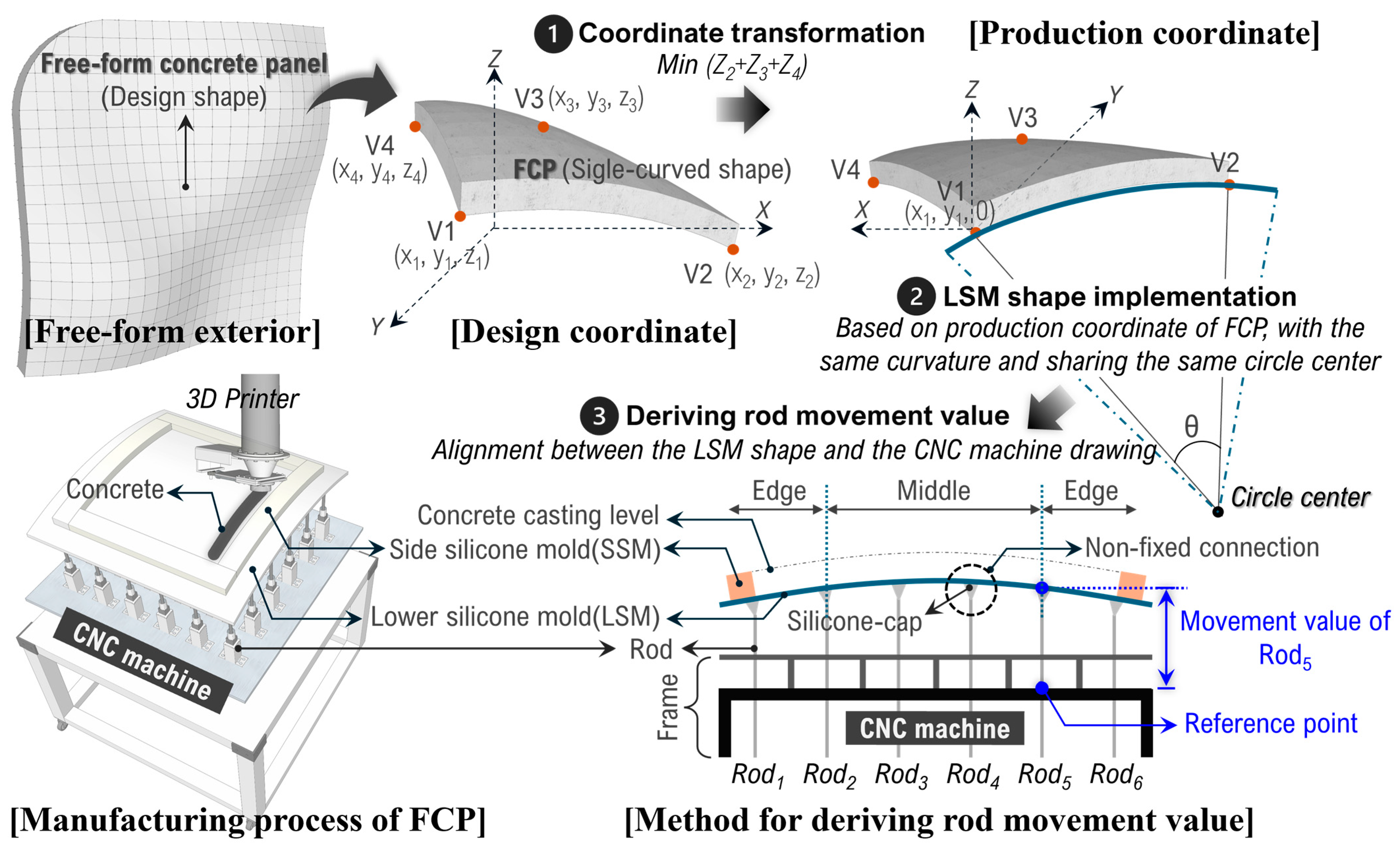
To manufacture FCPs, the design coordinates of the panel must first be converted into production coordinates, as illustrated in Figure 2. This coordinate transformation is required because FCPs are manufactured using a CNC machine, and the conversion enables a geometry that is easier to manufacture [14]. Subsequently, the movement values of the CNC rods required to realize the design shape of the LSM are obtained. As shown in Figure 2, the CNC machine consists of a frame and multiple rods. Silicone caps are attached to the ends of the rods. Next, to obtain the rod movement values, the design shape of the LSM is aligned with the CNC machine drawing, and the vertical distances between the rods and the LSM are calculated [17]. During the actual FCP manufacturing process, the LSM is placed on top of the CNC rods. A side silicone mold (SSM), which functions as a side mold, is then positioned on the LSM [14]. The rods are actuated according to the calculated movement values to realize the lower silicone mold shape, after which concrete is cast to manufacture the FCP. An important issue in this process is that the final shape of the implemented LSM inevitably differs from the design shape.
Figure 2.
FCP manufacturing process.
At the stage of determining the rod movement values, these values are merely the distance values at which the rods contact the designed LSM geometry in the 3D model. In addition, the rods of the CNC machine can move vertically with a precision of 0.01 mm according to those distance values, and thus the rod movement itself does not inherently contain error. However, because the LSM placed on top of the rods is made of elastic silicone, it cannot perfectly realize the design shape. If a lower mold made of steel, EPS, or another rigid material were fabricated using precise 3D machining technology, the design shape could be implemented accurately. However, the core technology required for the realization of free-form architecture is the ability to produce tens of thousands of geometrically different FCPs using reusable molds capable of smoothly implementing curved surfaces [16]. Existing free-form architectural projects have suffered substantial losses, including increased construction cost and prolonged construction periods, due to such technological limitations in panel production and installation [1]. In contrast, silicone has characteristics advantageous for the realization of free-form geometry, including reusability, surface continuity in curved shape implementation, water resistance, and durability [7]. For this reason, CNC machines and LSMs have been developed together up to the present. However, as noted above, because the LSM is elastic and there is still no technology capable of controlling that elasticity with sufficient precision, shape errors continue to occur despite the high precision of the CNC machine. In particular, these shape errors appear differently depending on the section of the LSM, for the following reasons.
Silicone caps are attached to the ends of the rods, and the LSM is placed on top of these silicone caps without any additional rigid fastening. Under this technical configuration, when a shape such as that shown in Figure 2 is implemented, the coordinates of the middle section have the highest z-values, and the z-values decrease toward the edges. First, in the middle section, the number of rods is greater than at the edges, and the rods support the deflection of the LSM from below. Therefore, when the design curvature is relatively gentle, shape precision in the middle section can be comparatively high. However, as the curvature in the middle section becomes steeper, the elastic behavior of the LSM can prevent complete contact between the silicone caps and the LSM, thereby reducing shape precision. In contrast, at the edges, the number of rods decreases from the middle section toward the boundaries. In addition, the LSM shape tends to sag downward toward the edges, and this sagging must occur to an appropriate degree in order to match the intended design shape. However, because the required sagging amount varies depending on the curvature of the target design shape, the shape precision of the LSM under different curvature conditions remains uncertain. Furthermore, sectional shape errors vary with changes in curvature due to differences in elastic behavior and deflection characteristics. In addition, during concrete casting, the LSM undergoes further deflection under the applied load, which also causes shape error. This deflection varies according to the designed thickness of the FCP, and accordingly, the tendency of shape error may also differ by section. For example, when the design curvature is steep, the error at the edges may become large; however, concrete cast in the middle section may flow toward the edges, causing the edge portions of the LSM to sag and thereby partially compensating for the original shape error. On the other hand, if the concrete cast in the middle section flows toward the edges, thickness loss may occur in the middle section, which can adversely affect quality. Accordingly, it is necessary to analyze both the overall and sectional shape errors of the LSM before casting under various combinations of curvature and thickness conditions. After casting, the lower shape errors of the FCP should be analyzed to evaluate the sectional tendencies of shape error occurrence before and after casting.
Several previous studies applying silicone-cap-based technologies have analyzed the lower shape through FCP manufacturing experiments. Yun analyzed lower shape errors through an FCP production experiment, but only examined the overall error range observed across the entire surface and simply performed a comparison with Lee’s fixed-connection method [14,15]. In contrast, Jeong designed a complex double-curved FCP, unlike earlier studies, and analyzed the implementation precision of the LSM [17]. In that study, the rod movement values were adjusted by section and the LSM shape was corrected through three successive stages; nevertheless, the errors were still not effectively reduced. This suggests that the mechanism by which the difficulty of implementing the LSM shape varies according to geometric complexity has not yet been sufficiently understood. In Ruan’s study, a similar lower mold implementation system was applied to produce free-form panels [18]. However, the study emphasized only the smoothness of the surface and did not specifically analyze the magnitude of the errors appearing in the lower shape; instead, the error level was estimated rather than measured. Kim investigated material modification by incorporating iron powder into the silicone mold to increase stiffness; however, the increased rigidity can reduce the mold’s ability to smoothly conform to curved geometries, and this approach was not adopted in the present study [19]. It was confirmed that the flexibility of the LSM was reduced by the addition of iron powder, which significantly decreased the precision of shape implementation. In addition, these studies commonly did not analyze how lower shape errors change according to variations in the FCP design conditions, such as curvature and thickness. As described above, there is still a lack of detailed research on the limitations of current lower-shape implementation technologies for FCPs and on the LSM shape errors caused by those limitations.
Accordingly, this study analyzes sectional error tendencies by combining design conditions of curvature and thickness and by dividing both the pre-casting LSM shape and the post-casting lower shape of the FCP into edge and middle sections. Specifically, the LSM is implemented according to each design combination, and sectional error tendencies and practical differences are verified through statistical analysis. After concrete casting, the lower shape errors of the FCP are compared with the pre-casting LSM shape to analyze deflection behavior and sectional error tendencies, and statistical tests are conducted to examine differences among groups. Finally, the shape errors observed under each design condition are discussed in relation to the allowable tolerance level within the current state of FCP manufacturing technology. Among currently developing FCP production technologies, 3D printing is the only currently available technology capable of implementing complex upper shapes [20,21]. Unlike conventional layer-by-layer extrusion on a flat x–y plane, this technique moves along curved vector directions inside a free-form mold. Consequently, although the technology is not yet fully established due to the high implementation complexity, the discussion in this study considers the current state of 3D printing technology. Based on the findings of this study, the understanding of sectional shape error characteristics is expected to contribute to improving production quality in the FCP manufacturing field. In addition, the results provide a practical basis for discussing allowable shape tolerances and establishing quality criteria for FCP production. Furthermore, the findings of this study may serve as a reference for future advancements in FCP manufacturing technologies, including the development of 3D printing-based production methods.
2. Research Methodology
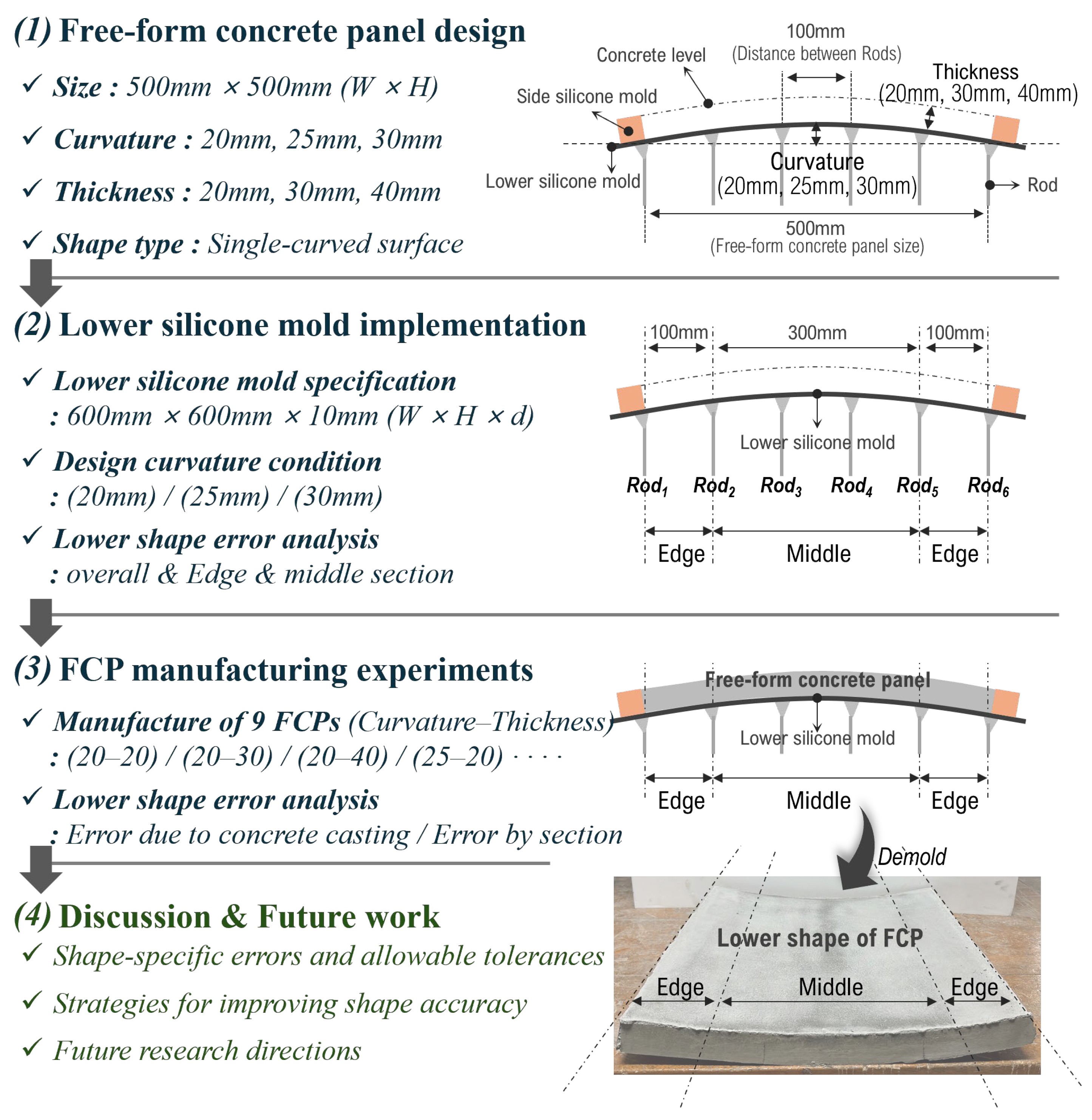
In this study, as illustrated in Figure 3, the research was conducted to analyze the sectional tendencies of shape errors in the lower silicone mold (LSM) and the lower surface of the free-form concrete panel (FCP). To this end, the FCP was first designed, and the curvature and thickness conditions were determined as follows. The curvatures were set to 20 mm, 25 mm, and 30 mm, referencing curvature ranges applied in previous FCP manufacturing studies. The thicknesses of the FCP were set to 20 mm, 30 mm, and 40 mm. The 20 mm and 30 mm thicknesses were based on those commonly adopted in previous experimental studies [1,9,10,11,12,13,14,16,17,18,19,22,23,24,25], while the 40 mm thickness was selected with reference to the exterior panels of an actual free-form building project, such as the façade of the National Museum of Qatar [24]. In addition, the geometry type was set as a single-curved surface. This simplified geometric condition was adopted to examine the fundamental tendencies of lower shape error under basic design conditions.
Figure 3.
Research flow.
Next, the lower silicone mold was implemented according to the designed FCP geometry, with curvature conditions as specified above. In this study, an LSM with dimensions of 600 × 600 × 10 mm (W × H × d) was used. The reason why the LSM dimensions were set 100 mm larger than the designed FCP area is that a side silicone mold (SSM) with a width of 50 mm is placed along each edge. The thickness of the LSM was set to 10 mm because previous FCP experimental studies showed that the highest shape precision was achieved when the LSM thickness was 10 mm [19]. The shape errors of the implemented lower silicone mold were then analyzed by dividing the surface into the overall area, edge section, and middle section for each curvature condition.
In previous experimental studies on FCP manufacturing, the lower shape was not analyzed by distinguishing between middle and edge sections. Therefore, in this study, the surface was divided into middle and edge sections based on the rod support locations. In the case of the middle section, because a larger number of rods are responsible for shape implementation within the overall area, the middle section was defined, as shown in Figure 3, as the four central rows of rod support locations, corresponding to the region from Rod 2 to Rod 5. In addition, because the number of rods contributing to shape implementation gradually decreases toward the edges, the two outer 100 mm regions on both sides, corresponding to Rod 1–2 and Rod 5–6, were defined as edge sections. Through this sectional classification, the error characteristics appearing in the edge and middle regions of the lower shape can be examined in detail.
Subsequently, concrete casting was carried out according to the aforementioned design conditions, and a total of nine FCPs were manufactured. The lower shape of the FCP after casting was compared with that of the lower silicone mold prior to casting. Both the overall shape error and the sectional shape errors were analyzed. Finally, based on the experimental results, the tendencies of shape error occurrence and the level of shape errors observed under each design condition were discussed in relation to the allowable tolerance within the current state of FCP manufacturing technology. Furthermore, future work aimed at improving lower shape precision and advancing FCP manufacturing technology is discussed.
3. FCP Manufacturing Experiment Results
3.1. Experiment Flow
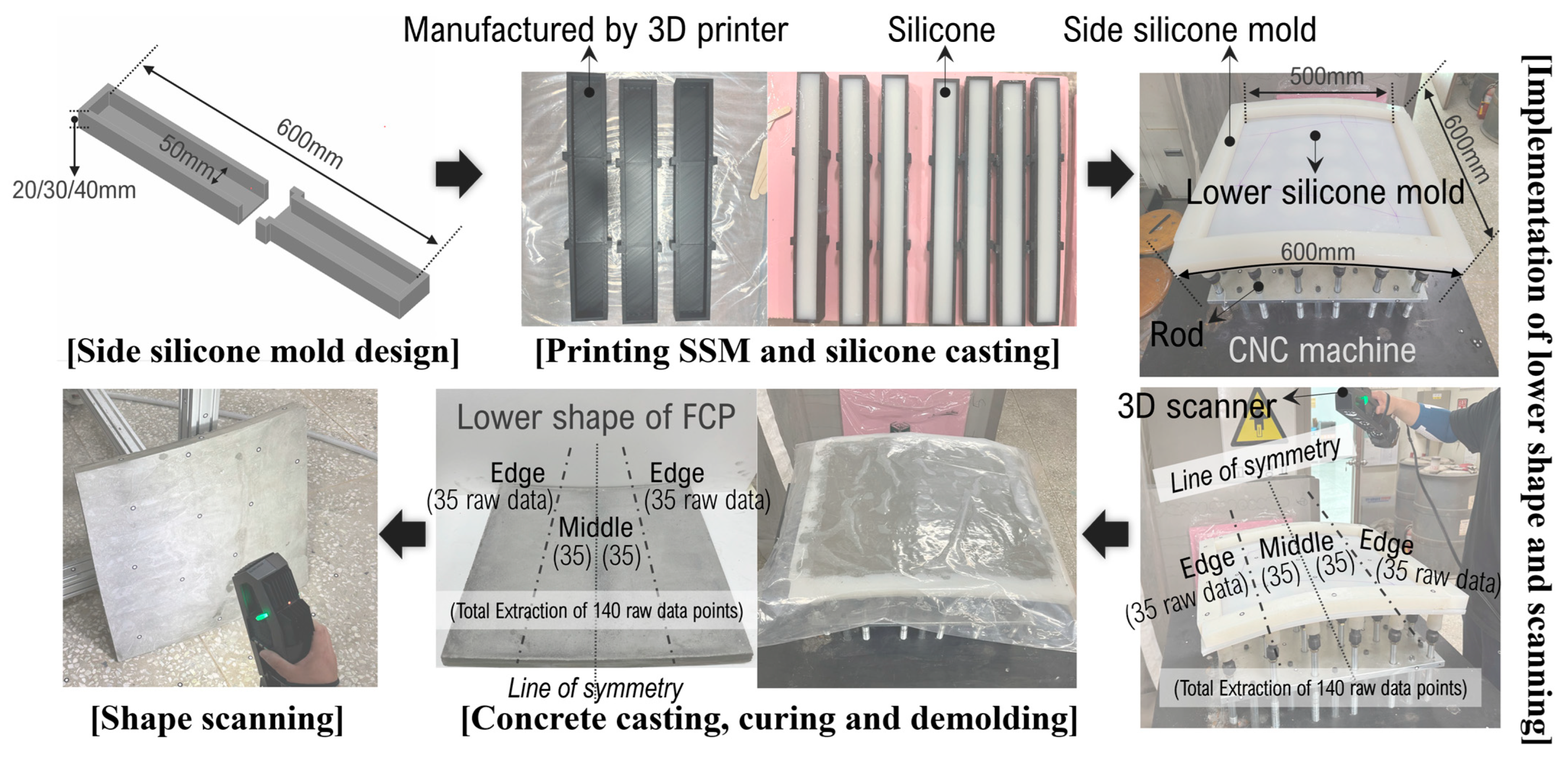
The flow of the FCP manufacturing experiment is presented in Figure 4. The manufacture of free-form concrete panels (FCPs) requires both a side silicone mold (SSM) and a lower silicone mold (LSM). To manufacture the SSM, a mold was first printed using a 3D printer with PLA filament. Liquid silicone was poured into the printed mold, and the SSM was manufactured after the required curing time.
Figure 4.
Flow of the FCP manufacturing experiment.
The SSM had a width of 50 mm and a length of 600 mm, while its thickness was varied according to the design conditions of the FCP. In addition, the Shore hardness of the SSM was 20. For the LSM, a flat silicone sheet was cut and used in consideration of the specifications of the computer numerical control (CNC) machine available to the research team. As described in Figure 4, the dimensions of the LSM were 600 × 600 × 10 mm (W × H × d), and its Shore hardness was 50.
The SSM and LSM were then placed on the CNC machine, and the curved geometry was implemented by operating the rods. As described in Figure 3, the target curvatures were 20 mm, 25 mm, and 30 mm. Subsequently, the shape errors of the lower silicone mold under each curvature condition were analyzed. To capture the geometry of the LSM, a 3D scanner (GO!SCAN SPARK, Creaform, Lévis, QC, Canada) was employed. The measurement precision of the shape acquisition was 0.05 mm. The scanned data was overlaid with the design geometry using VXinspect 10.0.0 software (Creaform, Levis, QC, Canada), from which raw error data were extracted. As illustrated in Figure 4, in this study, as mentioned earlier in Section 2, the edge and middle sections were distinguished based on the rod support locations. In addition, because the FCP geometry is symmetric with respect to the symmetry line, as shown in Figure 4, 35 raw data points were collected from each edge, resulting in a total of 70 raw data points for the edge sections. Likewise, 35 raw data points were collected from each middle-side region, resulting in a total of 70 raw data points for the middle sections. Accordingly, in this experiment, a total of 140 raw data points were collected for each design condition by combining the edge and middle sections. Because the same number of shape error data points were collected on both sides with respect to the symmetry line, the dataset can be regarded as representative of the shape characteristics of each section. In addition, the sample size is sufficient for conducting t-tests and ANOVA, and compared with previous FCP manufacturing experiments, the number of samples represents a relatively high sampling density per unit area [7,19]. Therefore, the present sampling strategy is considered sufficient to ensure the reliability of the experimental results.
After the geometry of the lower silicone mold was analyzed prior to concrete casting, the lower shape error of the FCP after casting was also derived and examined. In this stage, the lower surface of the FCP was similarly divided into the edge and middle section, and raw data were extracted following the same procedure.
3.2. Shape Error Analysis of Lower Silicone Mold
In this study, as illustrated in Figure 4, the shape errors of the lower silicone mold were analyzed for each curvature condition prior to concrete casting. For the error analysis, a total of 140 raw data points were used, consisting of 70 points from the middle section and 35 points from each edge. The shape errors of the lower silicone mold according to the curvatures of 20 mm, 25 mm, and 30 mm are summarized in Table 1. The mean error was defined as the arithmetic mean of the absolute values of the raw data obtained at each measurement point in order to quantitatively evaluate the magnitude of the lower shape error. Therefore, the mean error was used in the analysis as a representative indicator of the overall magnitude of the error appearing across the lower shape.
Table 1.
Descriptive statistics of shape errors in the lower silicone mold according to curvature.
The mean error was found to be 0.289 mm at a curvature of 20 mm, 0.345 mm at 25 mm, and 0.425 mm at 30 mm. These results indicate a tendency for the shape error of the lower silicone mold to increase as the curvature increases. Subsequently, as presented in Table 2 and Table 3, an analysis of variance (ANOVA) and post hoc tests were conducted to determine whether the differences among the three groups were statistically significant. The ANOVA results indicated that at least two groups showed significant differences. To identify which specific groups differed, a Bonferroni post hoc test was performed. The test results revealed significant differences between the 25 mm and 30 mm groups, as well as between the 20 mm and 30 mm groups. In contrast, no statistically significant difference was observed between the 20 mm and 25 mm groups. This implies that while the increase in curvature from 20 mm to 25 mm does not lead to a significant change in shape error, the elastic limitation of the lower silicone mold becomes more pronounced as the curvature exceeds 25 mm.
Table 2.
ANOVA results for shape errors of the lower silicone mold by curvature.
Table 3.
Post hoc comparison results of curvature-related shape errors (Bonferroni).
For a more detailed evaluation, the lower silicone mold was analytically divided into middle and edge sections, and the sectional characteristics of the shape errors were analyzed. As presented in Table 4, the shape errors observed at each curvature indicate that the errors tended to be slightly higher at the edges than in the middle section. Within the shape-control area, where the rods move vertically to control the deformation of the lower silicone mold so that it follows the designed curved geometry, the density and supporting height of the rods near the edges are relatively lower than those in the middle section. In addition, the rods and the lower silicone mold are connected through a detachable support system rather than a fixed bolt connection. Therefore, toward the edges of the shape-control area, the lower silicone mold inevitably exhibits deflection while following the design geometry. To verify whether the difference in shape error between the middle and edge sections was statistically significant, a t-test was conducted, as shown in Table 5. The results indicated that the difference between the two sections was not statistically significant. This outcome is considered to be influenced by the fact that deformation occurred across the entire lower silicone mold during the experiment. The raw error data collected near the boundary between the middle and edge sections likely affected the mean values of both sections, resulting in similar deformation tendencies. Accordingly, although larger errors were observed at the edges, these are presumed to originate from structural factors such as rod density, support height, and the elastic and deflection limits of the silicone. However, because the middle section was also affected by these influences, no statistically clear difference was detected.
Table 4.
Descriptive statistics of shape errors in the lower silicone mold according to curvature and analysis area.
Table 5.
t-Test results of shape errors between edge and middle areas according to curvature.
Furthermore, a clear increasing trend in shape error was identified in both the edge and middle sections with increasing curvature. As shown in Table 4, at the edges of the lower silicone mold, the mean error increased from 0.313 mm to 0.352 mm and 0.425 mm as the curvature increased from 20 mm to 25 mm and 30 mm, respectively. Similarly, in the middle section, the mean error increased from 0.266 mm to 0.339 mm and 0.424 mm with increasing curvature. To examine whether this increasing tendency was statistically significant, a one-way analysis of variance (ANOVA) followed by a Bonferroni post hoc test was conducted, and the results are summarized in Table 6 and Table 7. The analysis confirmed that, for both the edge and middle sections, significant differences were identified between the 20 mm and 30 mm curvature conditions. These findings indicate that statistically meaningful changes in shape error occur primarily when the curvature difference is sufficiently large, such as between 20 mm and 30 mm.
Table 6.
ANOVA results for shape errors by curvature and analysis area.
Table 7.
Post hoc comparison results of shape errors by analysis area and curvature (Bonferroni).
3.3. Lower Shape Analysis of Free-Form Concrete Panel
Next, the lower shape errors of the FCPs after casting were analyzed and compared with the shape errors of the lower silicone mold prior to casting. The thicknesses of the FCPs were set to 20 mm, 30 mm, and 40 mm under each curvature condition. The descriptive statistics of the shape errors before and after casting are summarized in Table A1. In addition, a t-test was conducted to determine whether the differences in mean error before and after casting were statistically significant, and the results are presented in Table A2.
Under the 20 mm curvature condition, the mean shape error increased after casting for all thicknesses (20 mm, 30 mm, and 40 mm). The t-test results confirmed that these increases were statistically significant. This indicates that concrete casting generates a statistically significant increase in shape error in the lower silicone mold.
For the 25 mm curvature condition, the results varied depending on thickness. When the thickness was 20 mm, the descriptive statistics showed an increase in mean error after casting; however, the t-test indicated that this increase was not statistically significant. This may be interpreted as a condition in which the elastic deformation of the lower silicone mold and the load-induced deformation from the concrete were relatively balanced. Therefore, the design condition of 25 mm curvature with 20 mm thickness may be considered relatively stable. When the thickness increased to 30 mm under the same curvature condition, the additional concrete load acting on the lower silicone mold resulted in a statistically significant difference between pre- and post-casting errors. In contrast, under the 25 mm curvature and 40 mm thickness condition, a significant increase in error due to increased load was expected. However, as shown in Table A2, the p-value was 0.070, indicating no statistical significance.
This can be explained by the fact that, under the 25 mm curvature condition, the curvature becomes steeper toward the edges compared to the 20 mm case. During casting, lateral pressure caused the SSM to be pushed outward, leading to lateral leakage of concrete and partial pressure release. In other words, the increase in load due to greater thickness and the simultaneous lateral pressure release offset each other, resulting in no statistically significant difference in mean error. Supporting this interpretation, as shown in Table A3 and Table A4, when comparing the post-casting lower shape errors between the edge and middle sections under this design condition, larger errors were observed at the edges. The t-test result (p = 0.000) confirmed that this difference was statistically significant.
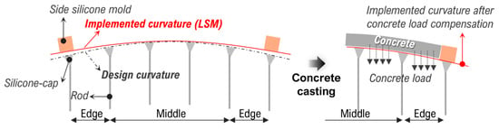
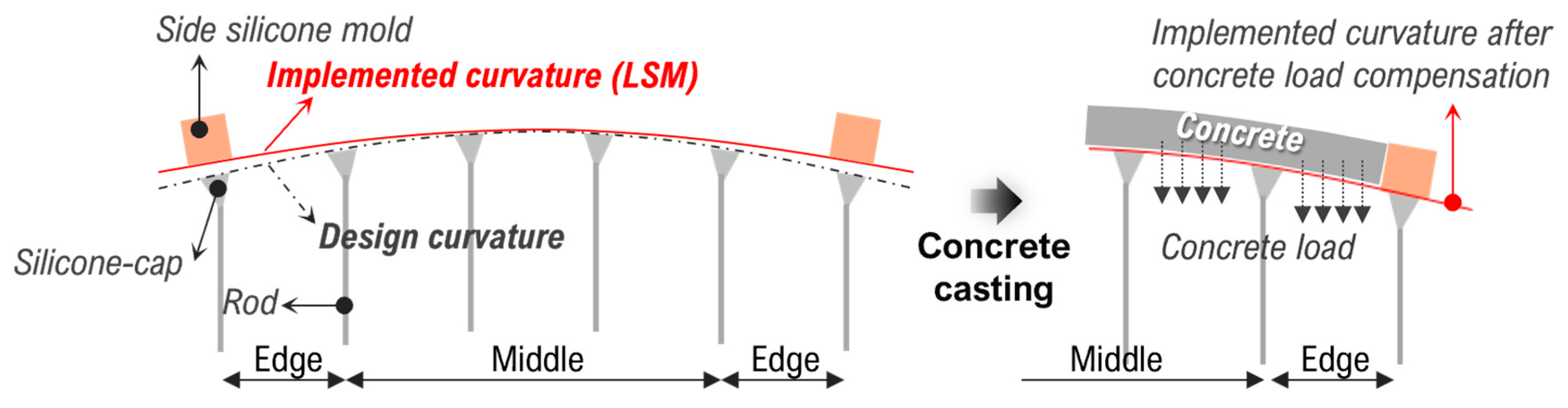
For the 30 mm curvature condition, the effect of thickness varied further. When the thickness was 20 mm, the mean error decreased after casting (from 0.425 mm to 0.313 mm), unlike the other design conditions. This reduction was statistically significant. This suggests that the concrete load partially compensated for the pre-existing deformation of the lower silicone mold. The mechanism by which the shape error of the LSM is compensated by the concrete load is illustrated in Figure 5. As mentioned earlier in Section 1, because the silicone-cap system uses a detachable connection between the rods and the LSM, each support point cannot be rigidly fixed. Therefore, as shown in Figure 5, when the curvature of the LSM increases and the middle section rises, shape errors occur toward the edges due to the elastic behavior of the LSM. However, when concrete is cast under this condition, the concrete load can instead cause the LSM shape to be corrected toward the original design geometry.
Figure 5.
Mechanism of LSM shape error compensation by concrete load.
Next, when the thickness was 30 mm under the 30 mm curvature condition, both curvature and thickness were relatively large compared to the other cases. As a result, the side silicone mold was significantly pushed outward during casting, leading to lateral pressure release, while an increase in shape error due to the greater casting thickness was also observed. Consequently, the difference in mean error before and after casting was not statistically significant. Furthermore, as shown in Table A3 and Table A4, no statistically significant difference was observed between the edge and middle sections after casting. Therefore, under this condition, the outward displacement of the side silicone mold makes it difficult to clearly identify a consistent trend in shape error.
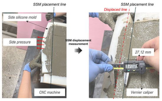
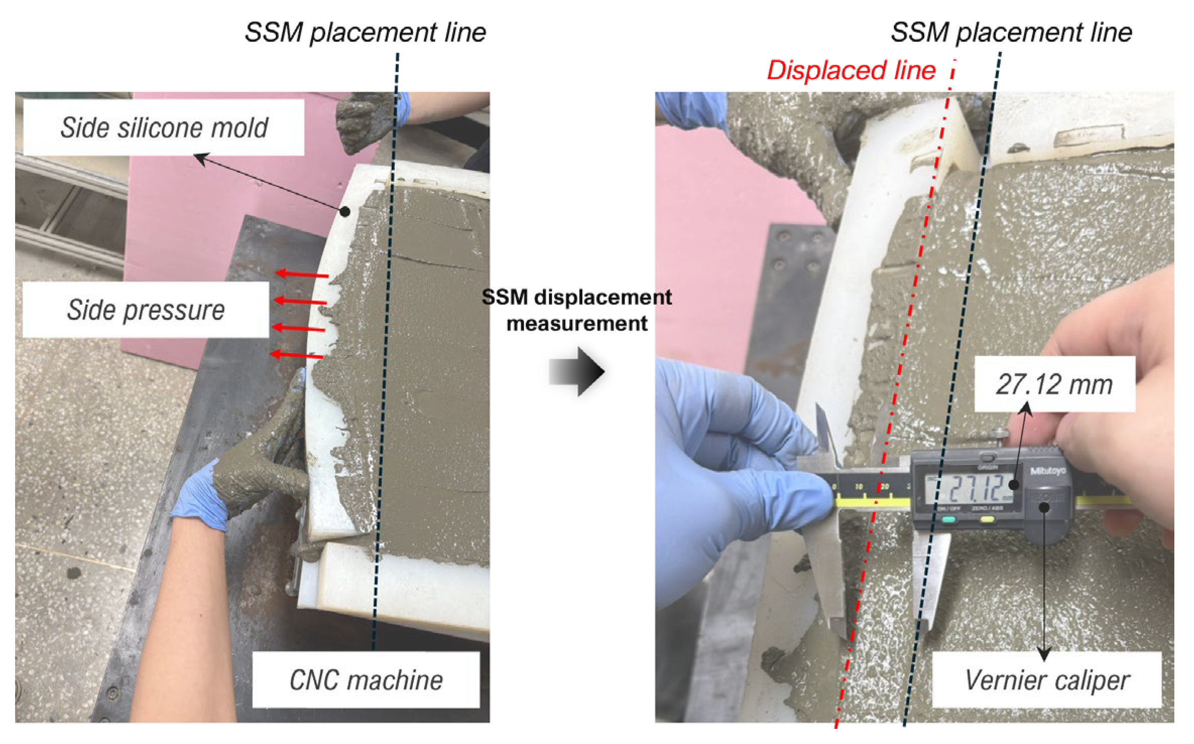
Finally, under the 30 mm curvature and 40 mm thickness condition, FCP manufacture was not possible because the SSM was pushed outward excessively by lateral pressure during casting. More specifically, because the concrete had not yet hardened, the SSM was displaced so severely that, unless it was manually held in place, the fresh concrete was lost to the outside of the mold. This experimental situation is illustrated in Figure 6. In this study, the displacement of the SSM was measured at the middle portion of the most severely displaced region, where the outward movement was greatest. The measurement was taken using a vernier caliper, and the displacement was found to be approximately 27.12 mm. It should be noted that this value was measured even while the SSM was being manually supported. Therefore, under the 30 mm curvature and 40 mm thickness condition, it was confirmed that FCP manufacture is not possible without additional lateral support. Although artificial support could have been applied to complete the manufacture, no further attempts were made in order to maintain the consistency of the experimental conditions and the integrity of the study. A comprehensive discussion of the experimental results is presented in Section 4, Discussion and Future Work.
Figure 6.
SSM displacement measurement at 30 mm curvature and 40 mm thickness.
4. Discussion and Future Work
In this study, the design conditions of free-form concrete panels (FCPs), including curvature and thickness, were combined, and the shape error tendencies were analyzed by dividing both the pre-casting lower silicone mold (LSM) geometry and the post-casting lower shape of the FCP into middle and edge sections. In particular, the effects of curvature increase, load-induced deformation caused by concrete casting, and sectional characteristics of shape errors were statistically examined in order to comprehensively interpret the structural and material causes of shape errors occurring during the FCP manufacturing process.
The experimental results showed that the shape error of the LSM prior to casting increased significantly as curvature increased, with statistically significant differences particularly observed between the 30 mm curvature condition and the 20 mm and 25 mm conditions. This tendency can be interpreted as the progressive manifestation of the elastic limitations of the silicone material as curvature increases. In addition, the edge sections exhibited relatively larger deformation tendencies than the middle section due to the lower rod density and supporting height, as well as the detachable support system rather than a fixed connection. However, because deformation occurred across the entire mold simultaneously, the difference in mean error between the middle and edge sections was not statistically significant.
The analysis of the lower shape of the FCP after casting revealed different behaviors depending on the design conditions. Under the 20 mm curvature condition, the shape error increased for all thicknesses, indicating that the concrete load induced additional deformation of the lower silicone mold. In contrast, under the 30 mm curvature and 20 mm thickness condition, the shape error decreased after casting, suggesting that the concrete load partially compensated for pre-existing deformation. Furthermore, under the 25 mm curvature–40 mm thickness condition and the 30 mm curvature–30 mm thickness condition, the side silicone mold (SSM) was pushed outward due to lateral pressure, resulting in partial pressure release. Consequently, the error-increasing effect due to load and the pressure-release effect offset each other, leading to statistically insignificant differences.
Compared with previous studies, the present study provides a more direct and systematic interpretation of lower-shape error behavior under controlled design conditions. Earlier studies, such as those by Yun, mainly reported the minimum and maximum values of shape error or the overall error range, which made it difficult to identify how errors developed by section or changed according to curvature and thickness conditions [13]. In addition, previous studies on double-curved FCPs, including the work by Jeong, attempted shape correction of the LSM through repeated adjustment of rod movement values, but the mechanism governing the occurrence and compensation of lower-shape error was not clearly identified. In contrast, this study statistically examined the lower-shape precision of the LSM under single-curved conditions by considering sectional differences and by comparing pre- and post-casting behavior. As a result, this study not only quantified the magnitude of lower-shape error more clearly, but also demonstrated that concrete load can either aggravate or partially compensate for pre-existing LSM deformation depending on the design condition. This finding distinguishes the present study from previous work that primarily described overall error ranges without clarifying the role of casting load or sectional behavior.
In particular, as shown in Figure 6, FCP manufacture was not possible under the 30 mm curvature and 40 mm thickness condition because the SSM was severely displaced outward by concrete lateral pressure during casting. This result indicates that, under the current experimental configuration, the combination of 30 mm curvature and 40 mm thickness exceeds the lateral resistance capacity of the SSM system. Accordingly, the result demonstrates that additional reinforcement or support technology is essential when both curvature and thickness increase beyond a certain level. From a practical perspective, two major technical directions can be considered to prevent such failure. First, methods for increasing the frictional resistance between the SSM and the LSM should be investigated. This may involve modifying the dimensions or material properties of the SSM to enhance interfacial frictional resistance. For example, frictional stability may be improved by increasing the contact area through a wider SSM or by increasing the self-weight of the SSM. In addition, material studies aimed at increasing the coefficient of friction between the SSM and the LSM are also required. Second, without changing the dimensions or material properties of the SSM itself, an external support system capable of resisting its outward displacement should be developed. Such a system may include rear-side supporting devices, auxiliary frames, clamping mechanisms, or a dedicated side-mold support system. These approaches should be considered key future research directions for ensuring the manufacturability of FCPs under more demanding geometric conditions.
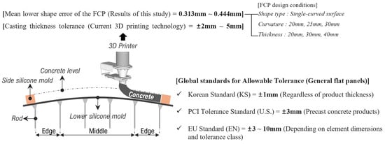
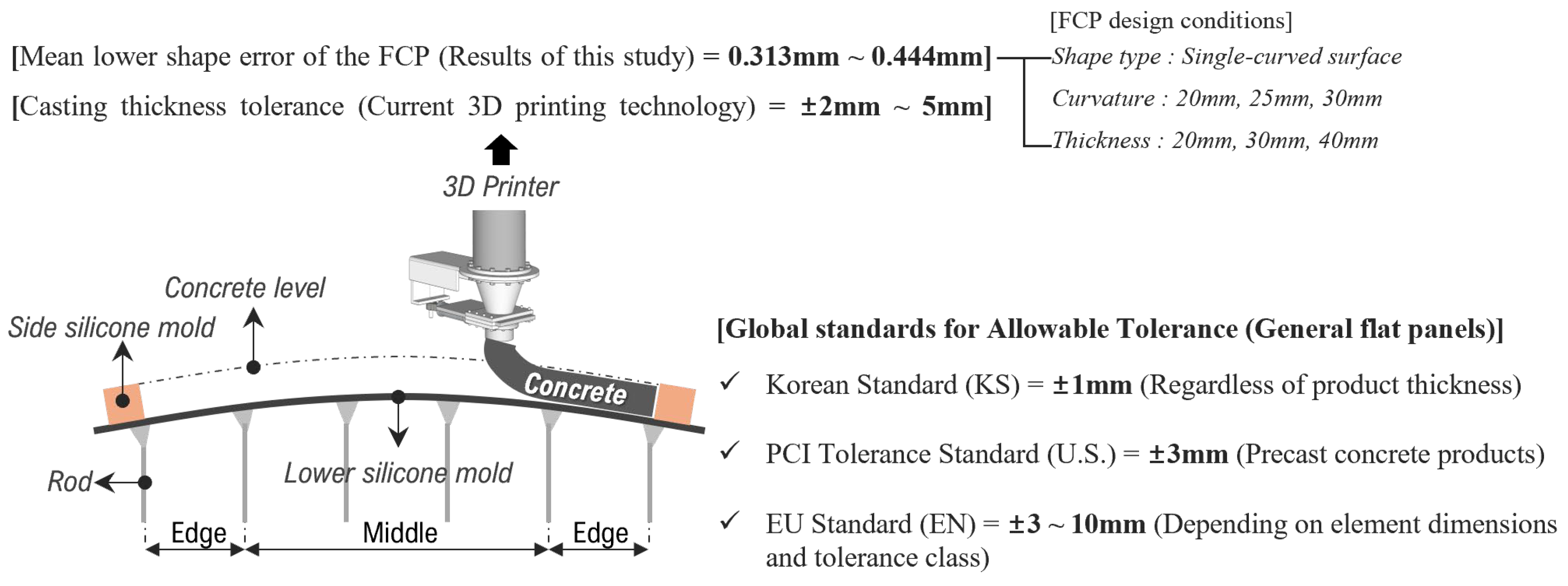
As shown in Figure 7, the mean lower shape error of the FCP obtained in this study ranged from approximately 0.313 mm to 0.444 mm. In contrast, currently reported 3D printing-based upper shape implementation technologies exhibit thickness errors of approximately ±2~5 mm [21]. These deviations originate from the layer-by-layer deposition process in the x–y plane during 3D printing, which inherently generates vertical accumulation errors. In other words, this corresponds to deflection of the upper shape and directly results in thickness deviations. Furthermore, as the number of accumulated layers increases, the magnitude of deviation tends to increase. When concrete is extruded onto free-form curved surfaces rather than flat planes, additional geometric instability may occur, leading to further increases in shape error.
Figure 7.
Comparison of FCP lower shape error with current 3D printing tolerance and global allowable standards.
Since no specific quality criteria have yet been established for FCPs, the results of this study were compared with global allowable tolerances applied to conventional flat precast concrete panels. As shown in Figure 4, The Korean Standard (KS) applies a highly strict tolerance of ±1 mm regardless of panel thickness [26]. The U.S. PCI standard generally allows a tolerance of approximately ±3 mm [27], while the European EN standard specifies tolerances ranging approximately from ±3 mm to ±10 mm depending on element dimensions and tolerance class [28]. When evaluated against these global standards for general flat panels, the thickness deviations currently observed in 3D printing-based FCP production (±2~5 mm) remain substantial and do not satisfy most conventional flat-panel tolerance criteria [21]. However, general flat panels are geometrically simple and do not require high-level fabrication complexity, allowing relatively small thickness tolerances to be achieved. In contrast, FCPs inherently involve curved geometries and rely on non-standard mold systems and advanced manufacturing technologies, which introduce additional sources of deformation and technical limitations. Therefore, directly applying flat-panel tolerance criteria to FCPs may not be appropriate, and dedicated quality standards specifically tailored to free-form geometries should be established.
From a scientific perspective, future research should expand the present experimental framework toward more diverse geometric and material conditions. In particular, repeated experiments are needed for double-curved FCP geometries, which are more complex than the single-curved geometry examined in this study. Additional studies should also investigate how changes in silicone material properties, such as stiffness, hardness, and elastic response, influence the shape precision of the LSM. Moreover, the influence of concrete material properties, including flowability, unit weight, and early-age rheological behavior, should be examined because these factors directly affect casting load and lateral pressure. Through such extensions, the relationship among mold deformation, material behavior, and geometric complexity can be understood more systematically. From a practical perspective, future work should focus on establishing a technical roadmap for precision control and manufacturability improvement of the current FCP production system. For the LSM, optimized control strategies should be developed according to curvature and thickness conditions. Rather than directly applying rod movement values derived from the design geometry, correction models should be established to compensate for experimentally observed elastic deformation and load-induced effects. Such models may support predictive calibration of rod movement values before casting. For the SSM, reinforcement technologies should be developed to prevent outward displacement under high-lateral-pressure conditions. This may include friction-enhancement strategies, dimensional optimization of the SSM, and independent support devices or mold-reinforcement systems. Ultimately, these technological improvements should contribute to the establishment of FCP-specific quality criteria and to the practical application of reliable free-form panel manufacturing in construction projects.
The sectional shape error analysis presented in this study is expected to provide foundational data for future development of FCP quality standards and for further advancement of manufacturing technologies.
5. Conclusions
This study analyzed the sectional characteristics of shape errors in the lower silicone mold (LSM) before concrete casting and in the lower shape of free-form concrete panels (FCPs) after casting under different curvature and thickness conditions. To this end, single-curved FCPs were designed with curvatures of 20 mm, 25 mm, and 30 mm and thicknesses of 20 mm, 30 mm, and 40 mm. The shape errors were examined by dividing the lower geometry into middle and edge sections, and statistical analyses were conducted to evaluate the significance of the observed differences.
The main findings of this study are as follows. First, before concrete casting, the shape error of the LSM increased as curvature increased. In particular, statistically significant differences were identified between the 30 mm curvature condition and the 20 mm and 25 mm conditions. This result indicates that the elastic limitation of the silicone mold becomes more pronounced as curvature increases.
Second, the sectional analysis showed that the edge sections tended to exhibit larger shape errors than the middle section. This tendency is associated with the lower rod density and support height near the edges and with the structural characteristics of the detachable silicone-cap support system. Although the difference between the middle and edge sections was not always statistically significant, the results confirm that sectional variation should be considered when evaluating lower-shape precision.
Third, after concrete casting, the lower shape behavior of the FCP varied depending on the combined curvature and thickness conditions. Under the 20 mm curvature condition, the mean error increased after casting for all thicknesses, indicating that the concrete load induced additional deformation of the LSM. In contrast, under the 30 mm curvature and 20 mm thickness condition, the mean error decreased after casting, demonstrating that the concrete load can partially compensate for pre-existing LSM deformation under certain design conditions. These findings show that the effect of concrete load is not unidirectional, but depends on the interaction between mold deformation, curvature, and casting thickness.
Fourth, under high-curvature and high-thickness conditions, lateral pressure on the side silicone mold (SSM) became a critical factor. In particular, under the 30 mm curvature and 40 mm thickness condition, FCP manufacture was not possible because the SSM was severely displaced outward during casting. This result indicates that the combination of 30 mm curvature and 40 mm thickness exceeds the lateral resistance capacity of the current SSM system and represents a practical failure boundary of the present manufacturing configuration.
From a scientific perspective, this study contributes to construction science by clarifying how lower-shape errors develop in reusable silicone mold systems according to sectional location, curvature, and casting thickness. In addition, the study provides experimental evidence that the deformation behavior of the mold under concrete load can either aggravate or compensate for pre-existing shape errors depending on the design condition. These findings contribute to a more systematic understanding of deformation behavior and load response in free-form concrete panel production.
From a technological and practical perspective, this study provides useful implications for the development of free-form panel manufacturing systems. The results indicate that precise control of the LSM should be approached differently depending on curvature and thickness conditions, and that reinforcement or support technologies for the SSM are essential under demanding design conditions. Furthermore, the findings of this study provide a practical basis for establishing FCP-specific quality criteria, rather than directly applying conventional tolerance standards for flat precast concrete panels.
In conclusion, this study demonstrates that the manufacturability and lower-shape precision of FCPs are governed by the combined effects of silicone elasticity, sectional support conditions, concrete load, and lateral pressure. The findings provide foundational data for improving reusable mold-based FCP production technology and for advancing future research on the precision control, structural stability, and quality management of free-form concrete panels.
Author Contributions
Conceptualization, K.J.; methodology, K.J. and S.K.; data analysis, K.J. and S.K.; writing—original draft preparation, K.J.; writing—review and editing, D.L.; visualization, K.J., S.K.; project administration, D.L. All authors have read and agreed to the published version of the manuscript.
Funding
This research was supported by Basic Science Research Program through the National Research Foundation of Korea (NRF) funded by the Ministry of Education (RS-2025-25429413). This work was supported by the Korea Institute of Energy Technology Evaluation and Planning (KETEP) grant funded by the Korea government (MOTIE) (RS-2023-00266248, Expert training program for Building Integrated Photovoltaics ecosystem).
Data Availability Statement
The original contributions presented in this study are included in the article. Further inquiries can be directed to the corresponding author.
Conflicts of Interest
The authors declare no conflicts of interest.
Abbreviations
The following abbreviations are used in this manuscript:
| FCP | Free-form concrete panel |
| LSM | Lower silicone mold |
| SSM | Side silicone mold |
| CNC | Computer numerical control |
Appendix A
Table A1.
Descriptive statistics of shape errors before and after concrete casting according to curvature and thickness.
Table A2.
t-Test results of shape errors before and after concrete casting according to curvature and thickness.
Table A3.
Descriptive statistics of shape errors occurring at edge and middle areas after concrete casting.
Table A4.
t-Test results of shape errors between edge and middle areas after concrete casting according to curvature and thickness.
References
- Jeong, K. Development of Two-Sided CNC and Side Mould Control Equipment for Automatic Manufacture of Free-Form Concrete Panel. Master ’s Thesis, Hanbat National University, Daejeon, Republic of Korea, February 2021. [Google Scholar]
- Wang, X.; Zhu, S.; Zeng, Q.; Guo, X. Improved Multi-Objective Hybrid Genetic Algorithm for Shape and Size Optimization of Free-Form Latticed Structures. J. Build. Eng. 2021, 43, 102902. [Google Scholar] [CrossRef] [Scilit]
- Shan, Z.; Chen, L.; Wang, Q.; Wu, H.; Gao, B. Simplified Quadrilateral Grid Generation of Complex Free-Form Gridshells by Surface Fitting. J. Build. Eng. 2022, 48, 103827. [Google Scholar] [CrossRef] [Scilit]
- Li, Z.; Hu, B.; Quan, G.; Gao, B.; Wang, Q. A Structured Grid Generation Framework Based on Parameterization for the Design of Free-Form Gridshells. J. Build. Eng. 2022, 62, 105400. [Google Scholar] [CrossRef] [Scilit]
- Na, S.; Kim, S.; Moon, S. Additive Manufacturing (3D Printing)-Applied Construction: Smart Node System for an Irregular Building Façade. J. Build. Eng. 2022, 56, 104743. [Google Scholar] [CrossRef] [Scilit]
- Olivieri, C.; Sibille, L.; Cocking, S.; Nazifi Charandabi, R.; Fabbrocino, F.; Adriaenssens, S. Design of Purely Compressive Shells under Vertical and Horizontal Loads through Machine Learning-Driven Form-Finding. Mech. Res. Commun. 2025, 148, 104491. [Google Scholar] [CrossRef] [Scilit]
- Jeong, K.; Lee, M.; Oh, J.; Lee, D. Development of Side Silicone Mold for Reducing Shape Error of Free-Form Concrete Panel. Buildings 2023, 10, 480. [Google Scholar] [CrossRef] [Scilit]
- Janssen, B. Double Curved Precast Load Bearing Concrete Elements. Master’s Thesis, Delft University of Technology, Delft, The Netherlands, March 2011. [Google Scholar]
- Schipper, H.R. Double-Curved Precast Concrete Elements. Ph.D. Thesis, Delft University of Technology, Delft, The Netherlands, September 2015. [Google Scholar]
- Gard, F. Flexible Mold: An Innovative Production Method to Produce Precast Double Curved Concrete Panels. Master’s Thesis, Eindhoven University of Technology, Eindhoven, The Netherlands, October 2013. [Google Scholar]
- Janmaat, M.W.J. Inflatable Mould: An Inflatable Moulding Technique for Producing Locally Manipulated Free-Formed Fibre Composite Panels. Master’s Thesis, Eindhoven University of Technology, Eindhoven, The Netherlands, May 2015. [Google Scholar]
- Oesterle, S.; Vansteenkiste, A.; Mirjan, A.; Willmann, J.; Gramazio, F.; Kohler, M. Zero Waste Free-Form Formwork. In Proceedings of the Second International Conference on Flexible Formwork (ICFF 2012), Bath, UK, 27–29 June 2012; pp. 258–267. [Google Scholar]
- Yun, J.; Youn, J.; Kim, J.; Lee, D. Development of Connection Technology between Multi-Point Press and Flexible Mold for Manufacturing Free-form Concrete Panel. Buildings 2022, 12, 767. [Google Scholar] [CrossRef] [Scilit]
- Yun, J. Development of Connection Technology and Operational Technology for the Lower Mold of Free-Form Concrete Panels. Master’s Thesis, Hanbat National University, Daejeon, Republic of Korea, February 2022. [Google Scholar]
- Sim, J.; Kim, H.; Park, G.; Kim, C.; Hong, D. Manufacturing Automation System of Freeform Concrete Formwork Using S-LOM Method. J. Korean Soc. Precis. Eng. 2020, 37, 43–50. [Google Scholar] [CrossRef] [Scilit]
- Kim, K.; Son, K.; Kim, E.D.; Kim, S. Current Trends and Future Directions of Free-Form Building Technology. Archit. Sci. Rev. 2015, 58, 230–243. [Google Scholar] [CrossRef] [Scilit]
- Jeong, K.; Yu, C.; Youn, J.; Lee, D. A Study of Lower Shape of Double-curved and Polygonal Free-form Concrete Panel. In Proceedings of the 10th International Conference on Construction Engineering and Project Management(ICCEPM), Sapporo, Japan, 29 July 2024. [Google Scholar]
- Raun, C.; Kirkegaard, P.H. Adaptive Mould A Cost-Effective Mould System Linking Design and Manufacturing of Double-Curved GFRC Panels. In Proceedings of the GRC 2015, Dubai, United Arab Emirates, 19–21 April 2015. [Google Scholar]
- Kim, J. A Study on Improving the Shape Error of the Lower Mold of Free-Form Concrete Panels Using Magnetic Force. Master ’s Thesis, Hanbat National University, Daejeon, Republic of Korea, February 2024. [Google Scholar]
- Costanzi, C.B.; Ahmed, Z.Y.; Schipper, H.R.; Bos, F.P.; Knaack, U.; Wolfs, R.J.M. 3D printing concrete on temporary surfaces: The design and fabrication of a concrete shell structure. Autom. Constr. 2018, 94, 395–404. [Google Scholar] [CrossRef] [Scilit]
- Xu, J.; Buswell, R.A.; Kinnell, P.; Biro, I.; Hodgson, J.; Konstantinidis, N.; Ding, L. Inspecting manufacturing precision of 3D printed concrete parts based on geometric dimensioning and tolerancing. Autom. Constr. 2020, 117, 103233. [Google Scholar] [CrossRef] [Scilit]
- Palikhe, S.; Kim, J.; Lim, J.; Kim, S. Systematic Analysis of Production Errors and Accuracy when using Pin-Bed Mold of Free-form Concrete Panels. KSCE J. Civ. Eng. 2018, 22, 3196–3203. [Google Scholar] [CrossRef] [Scilit]
- Lim, J.; Kim, D.; Kim, S. An experimental study for quality assurance of free-form concrete panels produced by CNC machine. J. Civ. Eng. Manag. 2018, 24, 145–154. [Google Scholar] [CrossRef] [Scilit]
- Menétrey, P. UHPFRC cladding for the qatar national museum. In Proceedings of the Symposium on Ultra-High Performance Fiber-Reinforced Concrete, Marseille, France, 1–3 October 2013. [Google Scholar]
- Kim, H.H.; Kang, E.C. Dongdaemun Design Plaza & Park. Mag. Korea Concr. Inst. 2010, 22, 100–104. Available online: https://www.dbpia.co.kr/journal/articleDetail?nodeId=NODE02257710 (accessed on 15 January 2026).
- Korean Standards & Certification. Available online: https://www.standard.go.kr/KSCI/standardIntro/getStandardSearchView.do?menuId=503&topMenuId=502&ksNo=KSF4736&tmprKsNo=KSF4736&reformNo=04 (accessed on 15 January 2026).
- Precast/Prestressed Concrete Institute. Available online: https://www.pci.org/ItemDetail?iProductCode=MNL-135-00H&Category=FIELD&WebsiteKey=5a7b2064-98c2-4c8e-9b4b-18c80973da1e (accessed on 15 January 2026).
- CENELEC. Available online: https://standards.cencenelec.eu/ords/f?p=CEN:105 (accessed on 15 January 2026).

Disclaimer/Publisher’s Note: The statements, opinions and data contained in all publications are solely those of the individual author(s) and contributor(s) and not of MDPI and/or the editor(s). MDPI and/or the editor(s) disclaim responsibility for any injury to people or property resulting from any ideas, methods, instructions or products referred to in the content. |
© 2026 by the authors. Licensee MDPI, Basel, Switzerland. This article is an open access article distributed under the terms and conditions of the Creative Commons Attribution (CC BY) license.