


Abstract
In this work, an accelerated non-uniform corrosion method controlled by time and current was employed to fabricate power-on accelerated corrosion specimens of hybrid steel fiber-reinforced concrete (HSFRC) gradient beams. Experimental research was conducted to investigate their impact resistance, revealing the dynamic response patterns of these gradient beams with varying steel fiber contents. By analyzing the evolutionary characteristics of impact load, displacement, energy dissipation, equivalent impact bearing capacity, and dynamic amplification factor, the influence of steel fibers with different sizes and contents on the bearing capacity degradation and mechanical properties of HSFRC gradient beams under the same corrosion conditions was clarified. The synergistic enhancement mechanism of multi-scale steel fibers in the beams was elucidated, highlighting the complementary effects of long fibers and short fibers at different stages of material damage. Results show that the incorporation of steel fibers can effectively improve the impact resistance of reinforced concrete gradient beams, with a maximum improvement of approximately 2.5 times. Compared with gradient beams reinforced with single long fibers, the peak impact force of HSFRC gradient beams increases by about 16%, and different steel fiber ratio plays a significant role in regulating impact resistance. Within the corrosion range of 3% to 5%, the equivalent impact bearing capacity of gradient beams is negatively correlated with the reinforcement corrosion rate.
1. Introduction
Concrete structures operate in environments accompanied by low-frequency vibrations or low-velocity impact loads, such as bridge engineering, underground engineering, protective engineering, marine engineering, and other fields. Moreover, corrosion of steel bars contained in concrete reduces their effective cross-sectional area, thereby deteriorating the mechanical properties of structures. Local tensile stresses caused by the accumulation of corrosion products, combined with impact loads on the structure itself, accelerate the cracking and spalling of the concrete cover. This renders concrete structures vulnerable to external corrosive substances, further accelerating corrosion and compromising the durability and safety of the entire structure. This phenomenon is particularly prominent in marine concrete engineering. Enhancing the impact resistance and crack resistance of concrete in harsh environments is a critical challenge for expanding its application range. Fibers have been used to improve the protective capacity of concrete. Fiber-reinforced concrete can effectively delay the corrosion of internal steel bars and enhance service performance. By incorporating steel fibers into concrete and distributing them uniformly, they can block crack initiation and bridge forces in the tensile zone, reduce tensile stress peaks, and effectively enhance concrete integrity and matrix toughness, meeting the requirements for high strength and toughness of concrete flexural members in practical engineering. Therefore, investigating the impact of the mechanical properties of marine concrete structures based on solving corrosion issues holds significant importance.
Incorporating various fibers into concrete is an effective approach to improve its toughness. Compared with plain concrete, fiber-reinforced concrete exhibits superior mechanical properties under impact loads. According to several published studies, hybrid fibers can enhance the ultimate strength, strain capacity, and strain-hardening behavior of concrete [1,2]. Li et al. [3] prepared six types of steel–polyethylene hybrid fiber-reinforced engineered cementitious composites and conducted dynamic compression tests under three loading rates, finding that steel fibers primarily bridge macro-cracks while polyethylene (PE) fibers bridge micro-cracks. Wu et al. [4] investigated the static and dynamic compressive properties of hybrid steel fiber-reinforced ultra-high-performance concrete (UHPC) and found that UHPC reinforced with 1.5% long fibers and 0.5% short fibers exhibited optimal static and dynamic mechanical properties. Shabakhty et al. [5] studied the fracture and mechanical properties of cementitious composites with different types and percentages of fibers and fly ash content, revealing that polyvinyl alcohol (PVA) and glass fibers had the most significant impact on load-bearing indices (tensile strength and fracture toughness), while PVA and polypropylene fibers were more suitable for energy absorption indices. Wu et al. [6] explored the effects of different steel fiber contents and shapes on the mechanical properties of UHPC, and Yoo et al. [7] investigated the structural performance of UHPC beams with varying steel fiber reinforcement ratios. Zhang et al. [8] used acoustic emission technology to study the influence of different fiber types and contents on the toughness and ductility of geopolymer mortar, finding that steel fibers were more beneficial for improving flexural strength and toughness, while polypropylene (PP) fibers showed better effects in enhancing ductility. Therefore, selecting an appropriate ratio of fibers with different shapes is crucial for improving the durability of concrete structures. Under impact loads, hybrid fiber concrete demonstrates and benefits from the synergistic response of each fiber component. Emphasis should be placed on the toughness of concrete materials and members, as good toughness facilitates energy absorption and mitigates damage to components and structures. However, concrete members in actual service often encounter complex and diverse environmental conditions, particularly corrosion, and the microscopic interaction mechanisms of different fibers remain insufficiently analyzed.
For steel fiber-reinforced concrete (SFRC), corrosion affects both steel fibers and steel bars [9]. SFRC can effectively delay the corrosion of internal steel bars and enhance the service performance of reinforced concrete structures [10]. Currently, many scholars have studied the microscopic mechanisms of steel fibers on concrete properties. Qiang et al. [11] conducted experimental studies on the acid corrosion resistance of SFRC, expressing the results in the form of compressive and flexural corrosion coefficients to reflect the corrosion degree. Zhao et al. [12] investigated the mechanical properties of corroded steel fibers and SFRC, finding that compressive strength decreases significantly after a certain corrosion period, while tensile strength gradually decreases with increasing corrosion time. O’Brien et al. [13] studied the mechanical behavior of stainless steel fiber-reinforced composites under accelerated corrosion, revealing that steel fiber-reinforced composites exhibit maximum corrosion resistance. Cristina et al. [14] explored the effect of corrosion on the pull-out performance of hooked steel fibers in self-compacting concrete, and Tri Thuong et al. [15] discussed the influence of corrosion degree and inhibitors on the pull-out behavior of deformed steel fibers. Within a certain range, as the corrosion degree increases, the pull-out resistance of deformed steel fibers increases by maintaining the fiber pull-out mode or even exhibiting slip-hardening behavior. Doo-Yeol et al. [16] found that for ordinary steel fibers, the pull-out and tensile properties of ultra-high-performance fiber-reinforced concrete (UHPFRC) increase as fiber corrosion reaches 5%. However, UHPFRC with surface-modified steel fibers exhibits performance degradation after a certain degree of corrosion. Thus, corrosion of steel fibers to a certain extent can affect the durability and safety of the entire structure.
Previous studies have demonstrated that fiber content and fiber type significantly influence the dynamic mechanical properties and impact resistance of fiber-reinforced concrete. An increase in fiber volume fraction generally enhances impact energy absorption and post-cracking ductility due to improved crack-bridging and stress redistribution under high loading rates [17,18,19,20]. Under drop-weight and impact loading conditions, steel fibers have been shown to effectively improve peak resistance and residual load-carrying capacity, while hybrid fiber systems combining different fiber lengths exhibit synergistic multiscale reinforcement effects [4]. In such systems, long fibers primarily contribute to macrocrack bridging and load transfer, whereas short fibers restrain microcrack initiation and propagation, resulting in improved deformation control and dynamic performance [21,22]. However, most existing studies focus on uncorroded specimens, and limited attention has been given to the combined influence of fiber gradation and reinforcement corrosion on impact behavior, particularly for gradient beams subjected to dynamic loading.
Corrosion of steel bars also impairs the mechanical properties of reinforced concrete and is one of the main causes of early deterioration and service life reduction of reinforced concrete structures [23,24,25]. Fu et al. [26] studied the shear performance of reinforced concrete beams under accelerated non-uniform corrosion, finding that corrosion unevenness exacerbates the propagation of corrosion-induced and load-induced cracks, leading to changes in shear failure modes. Tapan et al. [27] quantified the impact of steel bar corrosion on the structural performance of bridge columns. In the work of Vidal et al. [28], reinforced concrete members stored in a chloride environment for 17 years showed that their structural performance (flexural stiffness) was primarily affected by the corrosion of tensile steel bars. François et al. [29] investigated the effect of corrosion on the mechanical properties of steel in 27-year-old corroded reinforced concrete beams. Dai et al. [30] studied the influence of longitudinal steel bar corrosion on the impact performance of reinforced concrete beams, revealing that corrosion of longitudinal bars reduces impact force and reaction force, increases midspan displacement and energy absorption capacity of RC beams under impact loads, with all beams failing in shear critical modes and developing severe diagonal shear cracks below the impact point. Ou et al. [31] explored the effect of steel bar corrosion location on the seismic performance of corroded reinforced concrete beams, finding that as corrosion severity increases, the failure mode transitions from flexural–shear due to core concrete crushing to flexural-tension due to tensile steel bar fracture. Tamai et al. [17] studied the impact resistance of corroded reinforced concrete beams, noting that steel bar corrosion has a more significant effect on impact resistance than on quasi-static bearing capacity. Corrosion reduces the effective cross-sectional area of steel bars, leading to decreased tensile strength and ductility [17,32]. The accumulation of corrosion products generates local tensile stresses, causing cracking and spalling of the concrete cover, which makes the structure susceptible to external corrosive substances and accelerates corrosion, thereby affecting the durability and safety of the entire structure [33,34].
To address the above research gap, this study experimentally investigates the impact behavior of hybrid steel fiber-reinforced gradient beams subjected to reinforcement corrosion. Unlike previous experimental studies that primarily focused on uncorroded specimens or single-fiber systems, the present work systematically examines the coupled influence of hybrid fiber gradation and corrosion level under impact loading. Specifically, (i) hybrid long–short steel fiber configurations are incorporated into corroded gradient beams; (ii) the combined effect of fiber proportion and corrosion rate on peak displacement, energy dissipation, and residual load-bearing capacity is quantitatively evaluated; and (iii) the multiscale crack-bridging mechanism is interpreted in the context of corrosion-induced structural degradation. It should be noted that the investigation is limited to corrosion levels of 3–5% and laboratory-scale drop-weight impact conditions, providing a controlled basis for understanding the interaction between fiber gradation and corrosion under dynamic loading.
2. Materials and Methods
2.1. Raw Materials of Concrete
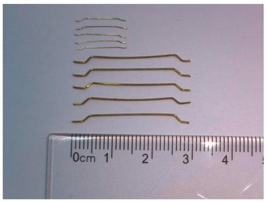
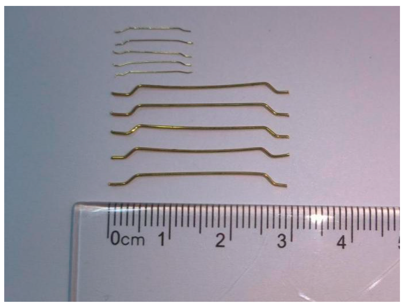
Five concrete mixtures were formulated with a fixed water–cement ratio of 0.53 for C40 grade concrete. The mix ratio is 1:0.53:2:3 (water:cement:sand:coarse aggregate). Ordinary Portland cement type P·O 42.5 was used. Fine aggregate consisted of river sand with a fineness modulus of 3.0. The coarse aggregate was 5–20 mm continuously graded crushed limestone containing less than 1.5% mud content. Tap water served as the mixing water. The complete mix designs are provided in Table 1. A polycarboxylate superplasticizer provided workability control. This admixture was dosed at 0.5% by binder weight and offered 25% water reduction. Long steel fiber contents were 0%, 0.50%, 0.75%, and 0.80%. Short steel fiber contents were 0%, 0.20%, 0.25%, and 0.50%. These ranges align with typical values reported in the literature [35,36,37,38,39]. Specimen labeling reflected the specific fiber contents used, i.e., L0.8S0.2 means that the contents of the long steel fiber was 0.80% and the short steel fiber was 0.20%. Both short and long steel fibers were copper-coated, hooked-end types, specifically A-1 65/13 and A-1 60/30, respectively. Their performance is shown in Table 2, and the fiber morphology is illustrated in Figure 1.
Table 1.
Proportions of concrete mix (kg/m3).
Table 2.
Performance of short/long steel fiber.
Figure 1.
Photographs of the long and short fibers.
To ensure the rigor and accuracy of the experiment, the concrete specimens cast synchronously were subjected to 28 d standard wet curing. Subsequently, splitting tensile strength, axial compressive strength, and elastic modulus tests were conducted in accordance with GB/T 50081-2019 Standard for Test Methods of Physical and Mechanical Properties of Concrete [40]. The splitting tensile strength was determined using 150 mm × 150 mm × 150 mm cube specimens, while both the axial compressive strength and the elastic modulus were measured on 150 mm × 150 mm × 300 mm prismatic specimens. The results are presented in Table 3.
Table 3.
Mechanical properties of concrete.
2.2. Fabrication and Corrosion Monitoring of Beams
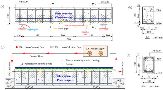
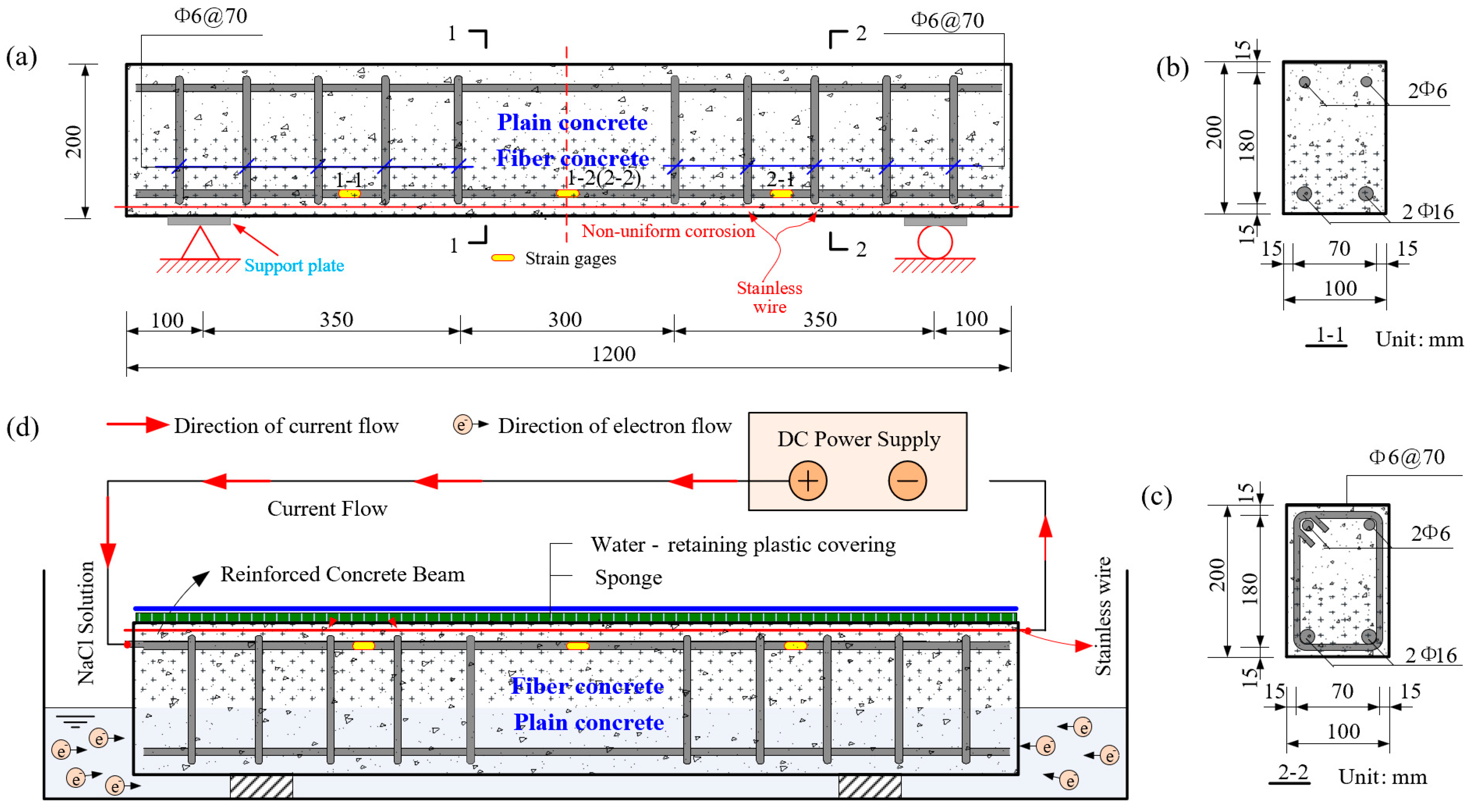
The beam specimens were designed with a layered concrete structure and detailed reinforcement layout as shown in Figure 2a–c. Each beam was reinforced with two 16 mm HRB335 deformed bars as main tensile reinforcement and two 6 mm HPB300 plain bars as compression reinforcement. Double-leg stirrups were made from 6 mm HPB335 steel. The reinforcement cage was assembled and tied prior to concrete placement. Strain gauges were bonded to the steel bars using a commercial cyanoacrylate adhesive (502-type, Deli, Ningbo, China) and subsequently sealed with epoxy resin for protection. To prevent electrical shorts during later accelerated corrosion testing, heat-shrink tubes insulated the junctions between stirrups and longitudinal bars, and plastic ties replaced metal wire for binding. A stainless steel wire was positioned 8 mm beneath the bottom longitudinal bars to facilitate non-uniform corrosion.
Figure 2.
Test setup and instrumentation layout (electrical resistance strain gauges, 120 Ω, gauge length 30 mm). (a) Reinforcement layout of layered steel fiber-reinforced concrete beam; (b) Section 1-1; (c) Section 2-2, and (d) Schematic diagram of electricity accelerating corrosion of steel bar (dimensions in mm).
A layered casting technique was employed to produce a functionally graded beam. The lower 100 mm layer consisted of plain concrete (mix L0S0), while the upper 100 mm layer contained various steel fiber concretes (L1S0, L0.8S0.2, L0.5S0.25, L0.5S0.5). This design leverages the superior tensile resistance of fiber-reinforced concrete in the beam’s tension zone while optimizing material cost. The upper layer was poured only after the lower layer had neared its initial set to prevent interlayer infiltration, ensuring a distinct interface (Figure 2a). Following casting, the specimens were demolded after 24 h and subsequently cured for 28 days under controlled conditions (20 ± 2 °C, 90% relative humidity), wrapped in plastic film to maintain moisture. All beams were cast in an upright position, with the main longitudinal reinforcement positioned at the top during casting.
An accelerated corrosion process was employed to simulate the degradation of steel reinforcement within the concrete beams. Prior to testing, all specimens were immersed in a 5% sodium chloride solution for 48 h to achieve saturation. The corrosion was then accelerated through an electrically driven activation process. The tensile reinforcement in the beam specimens was connected to the anode of a constant current DC power supply through pre-embedded conductors, while the cathode connection was made to the stainless steel wire (Figure 2d). The specific electrical parameters applied are summarized in Table 4. The corrosion state of the steel bars was monitored using the half-cell potential method [41,42] in accordance with ASTM C876-15 [43]. Measurements were systematically taken at 50 mm intervals across the bottom surface of each beam. A saturated calomel electrode was used for potential measurement, with the concrete surface maintained in a moist condition using a sponge saturated with a deionized water and detergent solution to ensure reliable electrical contact. The recorded potential values provide an indication of corrosion activity, where more negative readings correspond to a higher probability of active corrosion at the measurement location [44,45]. This non-destructive monitoring approach allowed for systematic tracking of corrosion progression throughout the experimental program.
Table 4.
Electrical parameters of longitudinal reinforcement.
2.3. Experimental Loading Mode
2.3.1. Static Testing
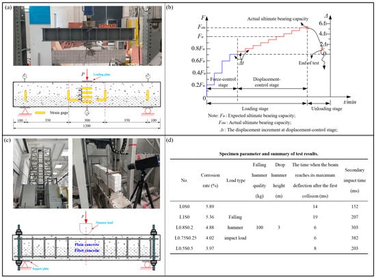
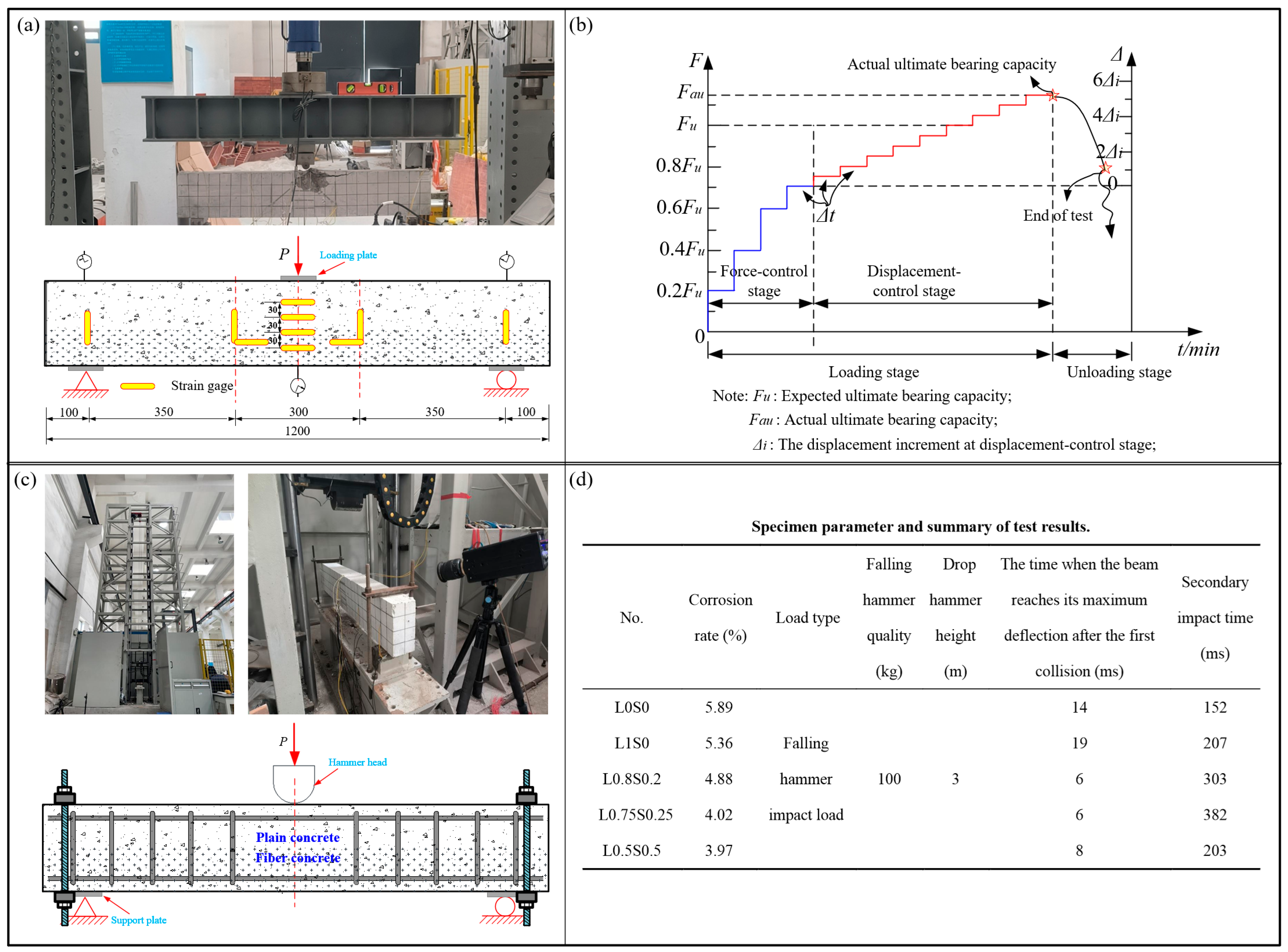
The static flexural performance was evaluated through three-point bending tests, with the experimental setup illustrated in Figure 3a. Electrical resistance strain gauges with a gauge length of 60 mm and resistance of 120 Ω were used to measure strain. Beams were simply supported with a fixed hinge at one end and a rolling hinge at the other. Loading was applied vertically at midspan through a hydraulic jack and distributed via a steel beam, with steel pads preventing local crushing. Strain gauges were mounted at the midspan of both longitudinal bars, and a displacement transducer measured midspan deflection. The DH3816N data acquisition system recorded all measurements at 1 kHz. The loading protocol followed a graduated scheme as shown in Figure 3b: 20% of the estimated ultimate load per step prior to cracking, which reduced to 10% after initial flexural cracking, and further reduced to 5% following shear cracking. The load within each stage was applied under load control at a controlled quasi-static rate to ensure stable crack development. Each load stage was maintained for 10 min. Testing terminated when concrete crushing occurred or when significant load reduction was observed. The flexural and shear capacities of the test beams were calculated using empirical Formulas (1) and (2) for concrete bearing capacity [46]. Based on the mechanical properties of concrete specimens and steel bars provided in Table 1 and Table 2, the predicted flexural and shear capacities of the reinforced concrete beam were 63.08 kN, while the actual ultimate load was 69.112 kN.
Figure 3.
Static loading: (a) Static test loading device and placement of strain gauges on the surface of the test beam, and (b) Loading regime for bending beam specimens. Impact test: (c) Drop weight impact testing machine and impact test device schematic diagram, and (d) Specimen parameter and summary of test results.
2.3.2. Impact Testing
Drop-weight impact tests were conducted using the heavy-duty testing machine shown in Figure 3c. A 100 kg hammer was released from rest in free fall from a height of 3 m, without any additional propulsion or acceleration (Figure 3d), producing a low-velocity impact at the midspan with a shear-span ratio of 2.5. The test setup incorporated multiple measurement systems: the DH-5960 ultra-dynamic system acquired data at 100 kHz; a laser displacement sensor measured midspan deflection; a high-speed camera recorded at 2000 fps; and an accelerometer mounted on the hammer captured impact acceleration. To ensure safety and data reliability, the supports were secured with bolted plates and spring washers to prevent beam rebound and excessive longitudinal movement during impact.
3. Results and Discussion
3.1. Static Testing Analysis
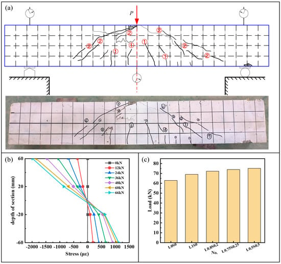
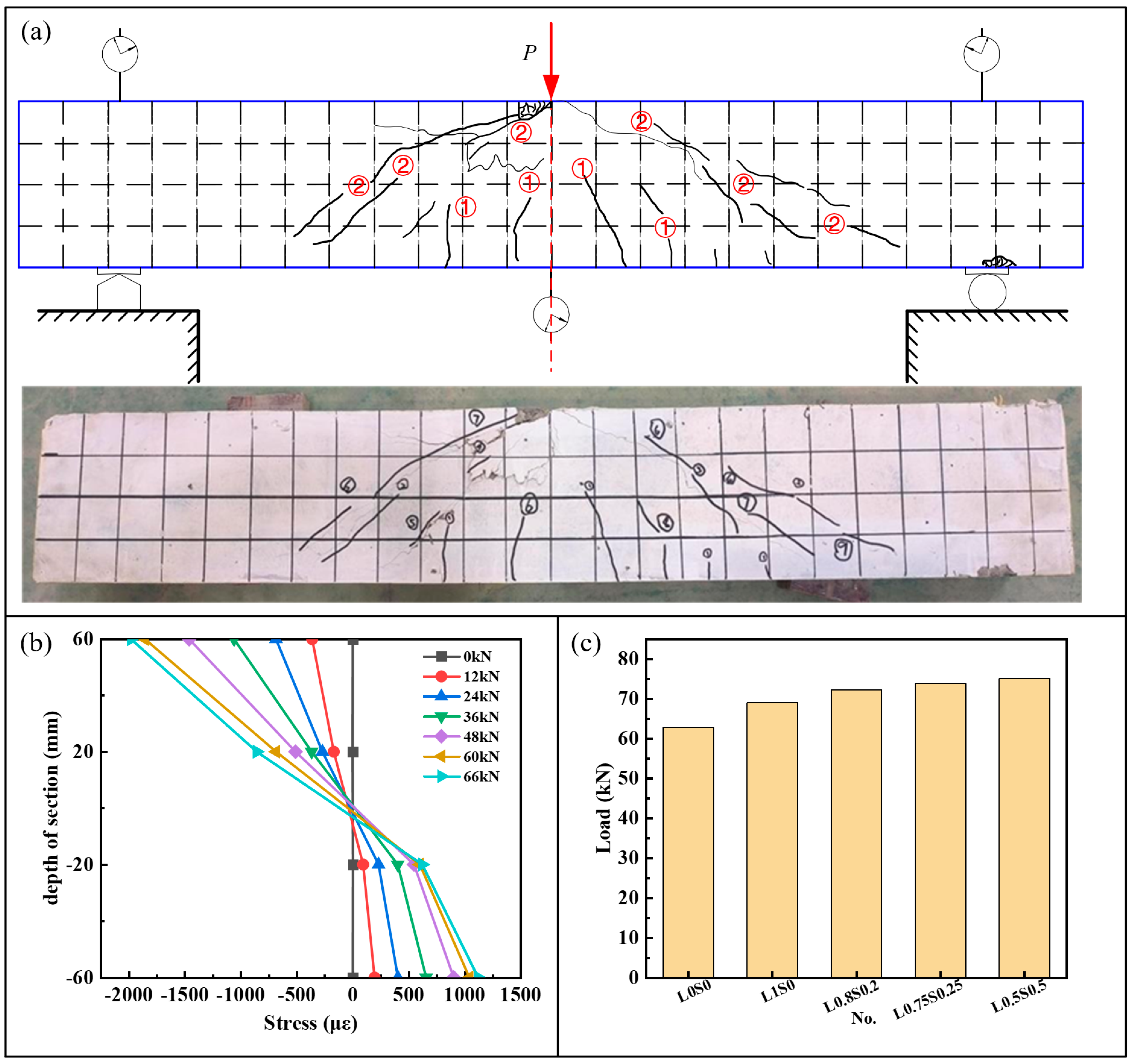
Static testing is an indispensable component in investigating the impact resistance of accelerated non-uniformly corroded HSFRC. It provides a solid foundation and critical support for accurately evaluating impact resistance, deeply understanding material mechanical behaviors, and facilitating structural safety assessments and designs. Furthermore, indices such as the ratio of equivalent impact bearing capacity to static ultimate bearing capacity and the ratio of peak impact force to static ultimate bearing capacity-discussed later in this paper-serve as key indicators reflecting the impact resistance of beams. Figure 4c shows the static ultimate bearing capacity of each concrete beam. During the static test, beam L1S0 exhibited typical shear failure characteristics (Figure 4a). In the early stages of the test, no significant cracking was observed in the concrete beam. However, when the applied load reached 52% of the failure bearing capacity, four straight cracks simultaneously appeared at the midspan of the member, specifically the four Type ① cracks near the beam bottom in Figure 4a, indicating that the elastic deformation capacity of the beam was approaching its limit. As the load increased further, distinct diagonal cracks emerged on the beam surface when the load reached 67% of the failure bearing capacity, specifically the two Type ② cracks shown in Figure 4a, indicating that shear force dominated the load borne by the beam. After adjusting the loading steps, the number of diagonal cracks on the beam gradually increased, with their widths expanding accordingly [47]. Eventually, the concrete beam failed with a sudden drop in bearing capacity. In summary, the failure mode of the concrete beam was a bending-shear failure.
Figure 4.
(a) Beam failure mode (L1S0, Type ①: flexural cracks; Type ②: diagonal shear cracks), (b) Strain distribution of concrete in cross section, and (c) Static ultimate bearing capacity of each concrete beam (mean value of two specimens per configuration).
During loading, the midspan of the beam experiences the maximum bending moment, making it the critical region where plastic deformation first occurs and cracks or failure are most likely to initiate. Its stress state directly reflects the overall load-bearing performance and deformation characteristics of the beam. As shown in Figure 4b, the strain distribution of concrete in the midspan cross-section and the variation in the neutral axis conform to the plane section assumption. Under low loads, the surface strain of the beam exhibited a linear distribution. With increasing load, strain variations in the tensile zone of HSFRC were relatively small, while those in the compressive zone were more pronounced; moreover, strain variations diminished as the measurement point approached the beam bottom. Compared to conventional concrete, steel fibers in HSFRC effectively bear tensile stress, thereby enhancing the tensile strength of the concrete. In practical applications, this characteristic enables SFRC to better resist crack initiation under tensile stress. Additionally, HSFRC demonstrates excellent crack control capabilities. When subjected to tension, steel fibers disperse and absorb part of the tensile stress during their pull-out process, effectively slowing crack propagation on the concrete surface. Even under high tensile stress, the HSFRC structure maintains good overall stability. Based on plane section analysis, therefore, replacing concrete in the tensile zone of the gradient beam with HSFRC effectively disperses the tensile stress borne by longitudinal reinforcement. This reduces the stress and strain in the steel bars, improving structural safety performance. Concurrently, strain in the tensile zone of concrete is reduced, further enhancing structural stability and durability.
In summary, during the loading process of steel fiber-reinforced concrete gradient beams, the incorporation of steel fibers increases the cracking load and overall stiffness of the beam, while significantly inhibiting crack development [48].
3.2. Damage Mode Characteristic
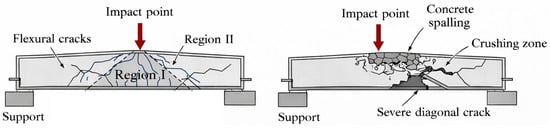
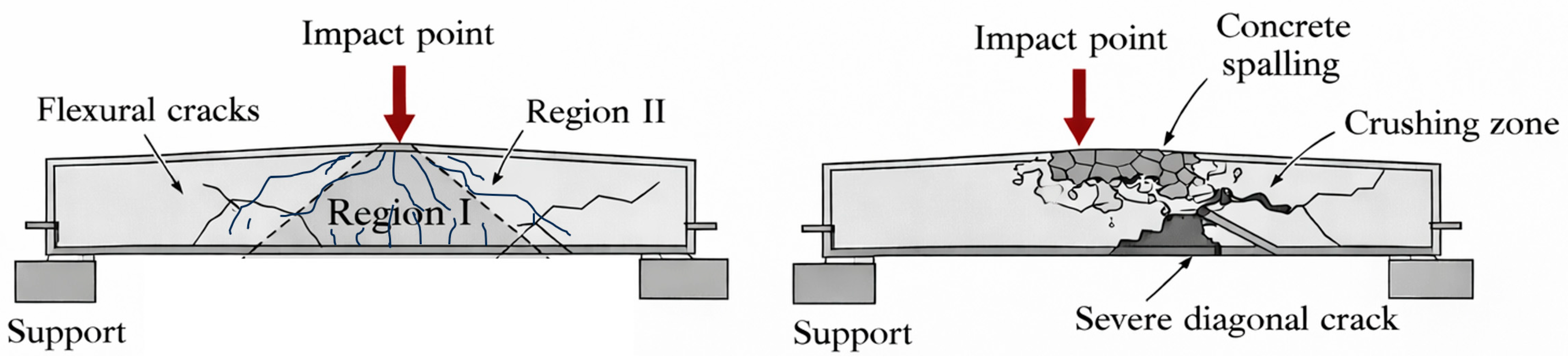
The failure mode of a beam is a core characteristic reflecting its impact resistance, directly related to the structural bearing capacity, deformation laws, and failure mechanisms under impact loading. Thus, the identification and analysis of failure modes constitute one of the key contents of this study. Based on experimental observations, two typical failure modes and one combined failure mode were identified. The two typical failure modes are as follows: (1) Overall failure mode: The beam is divided into two regions: Region I, an isosceles right triangle with the impact point at the vertex in the midspan area, and Region II (the remaining area). Within 2 ms of impact initiation, two diagonal cracks and a few vertical flexural cracks appeared in Region I. Subsequently, multiple diagonal cracks originating from the beam web propagated toward the beam top (e.g., L0.5S0.5 and L0.75S0.25). Eventually, cracks in Region I outnumbered those in Region II, becoming the dominant failure cracks, while crack growth in Region II was insignificant, resulting in a flexural failure mode of the beam. (2) Local failure mode: This mode differs significantly from other failure modes, primarily in the degree of concrete spalling. For instance, beam L0S0 exhibited concrete splashing at the initial moment of impact; as deflection increased, the concrete in the impact zone was crushed under pressure. After the impact test, concrete fragments were observed to fall off, and even exposed top bars were visible in the impact zone. Some concrete beams exhibited characteristics combining the two failure modes. A schematic illustration of the two typical failure modes observed in this study is provided in Figure 5.
Figure 5.
Schematic illustration of two typical failure modes under impact loading: (left) overall failure mode; (right) local failure mode.
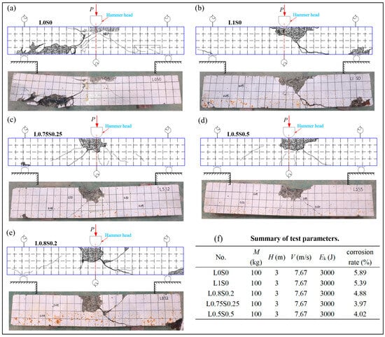
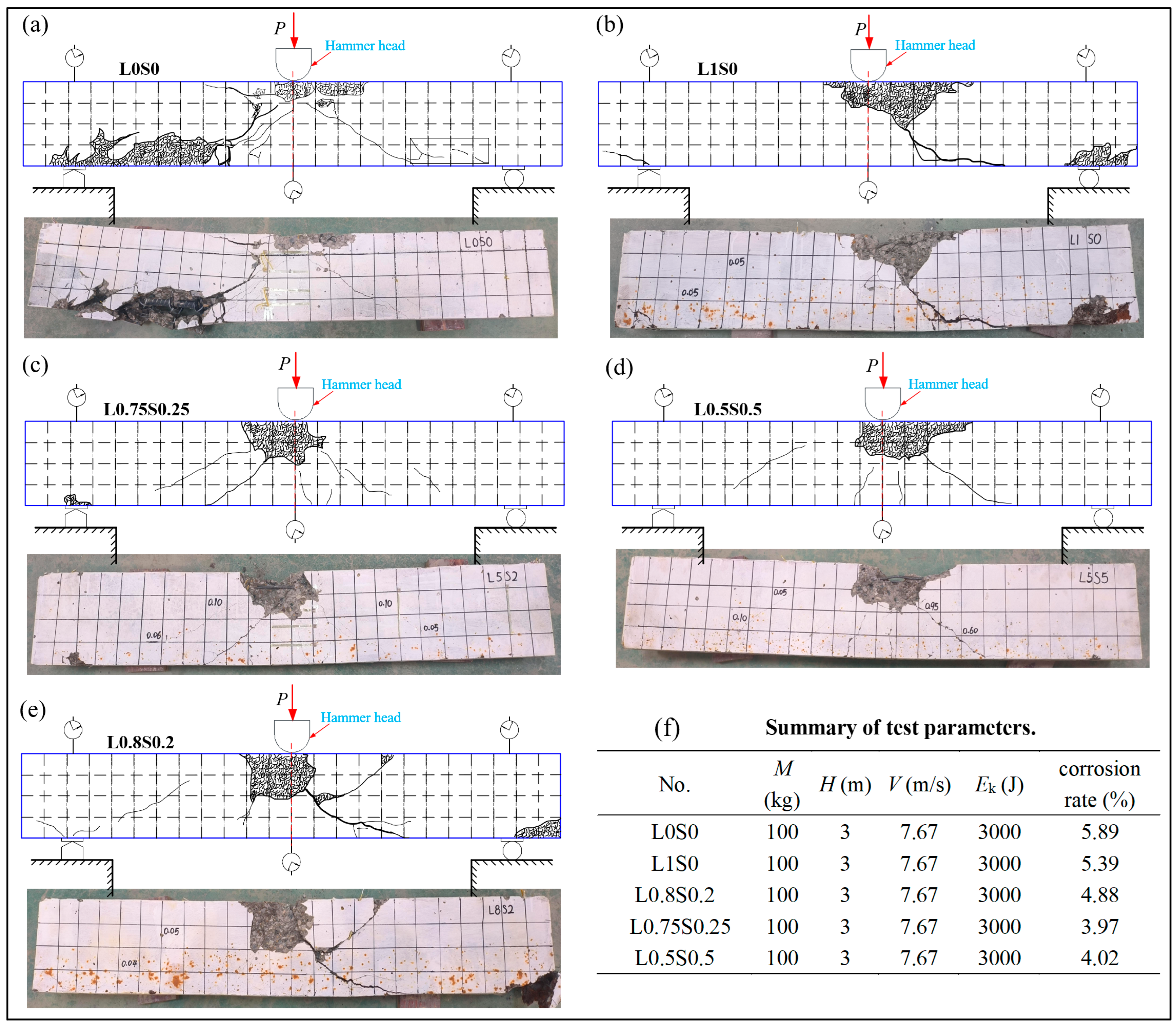
Combining Figure 6a and Figure 3d, taking beam L0S0 as an example, the time to reach maximum deflection after the first impact was t = 14 ms. Before reaching maximum deflection, the drop hammer contacted the upper surface of the concrete beam, with minor concrete debris splashing near the impact point. Immediately afterward, diagonal cracks at 45° outward and towards the supports appeared in the midspan impact zone; these cracks propagated linearly outward, accompanied by concrete spalling around them, and the beam exhibited slight downward deflection overall. At t = 14 ms, cracks fully developed from the top impact zone at a 45° diagonal angle, with increased width; concrete near the knife-edge supports was crushed, and concrete between the supports and adjacent 45° diagonal cracks began to loosen and fall off, with the beam reaching maximum downward deflection. Subsequently, both the drop hammer and the test beam rebounded to some extent. When the rebound velocity of the drop hammer exceeded that of the beam, they separated, the hammer was lifted, and the beam remained fixed in place due to the fixed supports at its ends. At t = 152 ms, the drop hammer collided with the beam a second time, causing further increases in beam deflection. Thereafter, the beam-hammer system underwent several rebound and drop cycles with an 11 ms period, and the vertical harmonic vibration of the beam gradually stabilized. Compared with plain concrete, HSFRC beams exhibited a later secondary collision time, indicating less impact energy absorption by the beam; the excess energy was converted into hammer kinetic energy after becoming deformation energy of the steel fiber beam, which was reflected in the secondary collision time in the impact test. Among HSFRC beams, L0.8S0.2 and L1S0 exhibited the earliest secondary impact times, indicating lower kinetic energy transferred to the hammer; in contrast, L0.5S0.5 and L0.75S0.25 showed later secondary impact times, corresponding to higher kinetic energy of the hammer.
Figure 6.
Image of Reinforced Concrete Beam after Impact and Schematic Diagram of Load-Induced Cracks: (a) L0S0, ηa = 5.89%; (b) L1S0, ηa = 5.36%; (c) L0.75S0.25, ηa = 4.02%; (d) L0.5S0.5C, ηa = 3.97%; (e) L0.8S0.2, ηa = 4.88%; (f) Summary of test parameters.
The impact test images of L0S0 (a plain concrete beam without steel fibers) revealed large corner rotations and significant midspan deflection. The beam failed to return to its original alignment because of plastic deformation of the concrete and reinforcing bars. Severe concrete spalling occurred at the corners, with concrete cover peeling from the midspan to the supports, exposing internal longitudinal bars and rendering them vulnerable to external environmental corrosion. Main cracks initiated below the impact point and extended diagonally at 45° to the lower half of the beam and support positions, forming a triangular pattern with narrowing widths from bottom to top. Transverse cracks appeared near the midspan impact point in the upper half of the beam, where concrete was crushed into powder. For HSFRC gradient beams (L1S0, L0.8S0.2, L0.75S0.25 and L0.5S0.5 as shown in Figure 6a–e), smaller corner rotation angles and less midspan deflection were observed, with minimal corner concrete spalling (only corner concrete peeling of L0.8S0.2 was visible in Figure 6e). These beams exhibited fewer and narrower cracks, with main cracks biased toward one support. As shown in Figure 6d, L0.5S0.5 even exhibited narrower cracks in the lower HSFRC portion compared to the upper plain concrete section. Severe concrete spalling occurred at the impact point, exposing internal distribution bars with significant bending. The upper plain concrete section of the gradient beam suffered severe damage, with extensive concrete peeling on the beam surface forming diagonal cracks, while the lower section with single/double steel fiber reinforcement was less damaged. As shown in Figure 6d, the maximum crack width in the HSFRC portion of L0.75S0.25 was even smaller than that in the plain concrete portion. The underlying reasons are as follows: (1) The lower HSFRC portion had higher stiffness and dissipated less energy through deformation, thus requiring the upper plain concrete portion to dissipate more energy via deformation and spalling. (2) Due to the higher stiffness of the HSFRC beam, the impact hammer experienced greater reaction force upon contact, and the elastic deformation energy of the beam was converted into hammer kinetic energy, enabling the hammer to gain velocity again, separate from the beam, and fall for a secondary impact, thereby exacerbating damage to the impact point.
3.3. Impact Force and Mid-Span Deflection Time History Curves
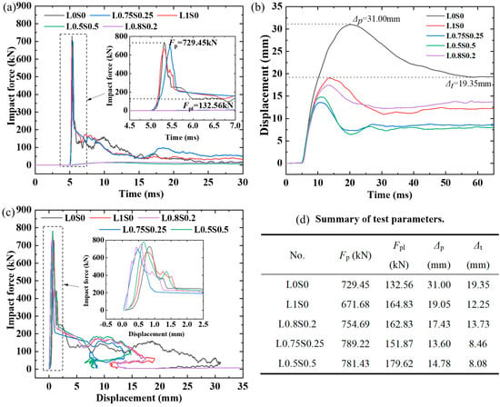
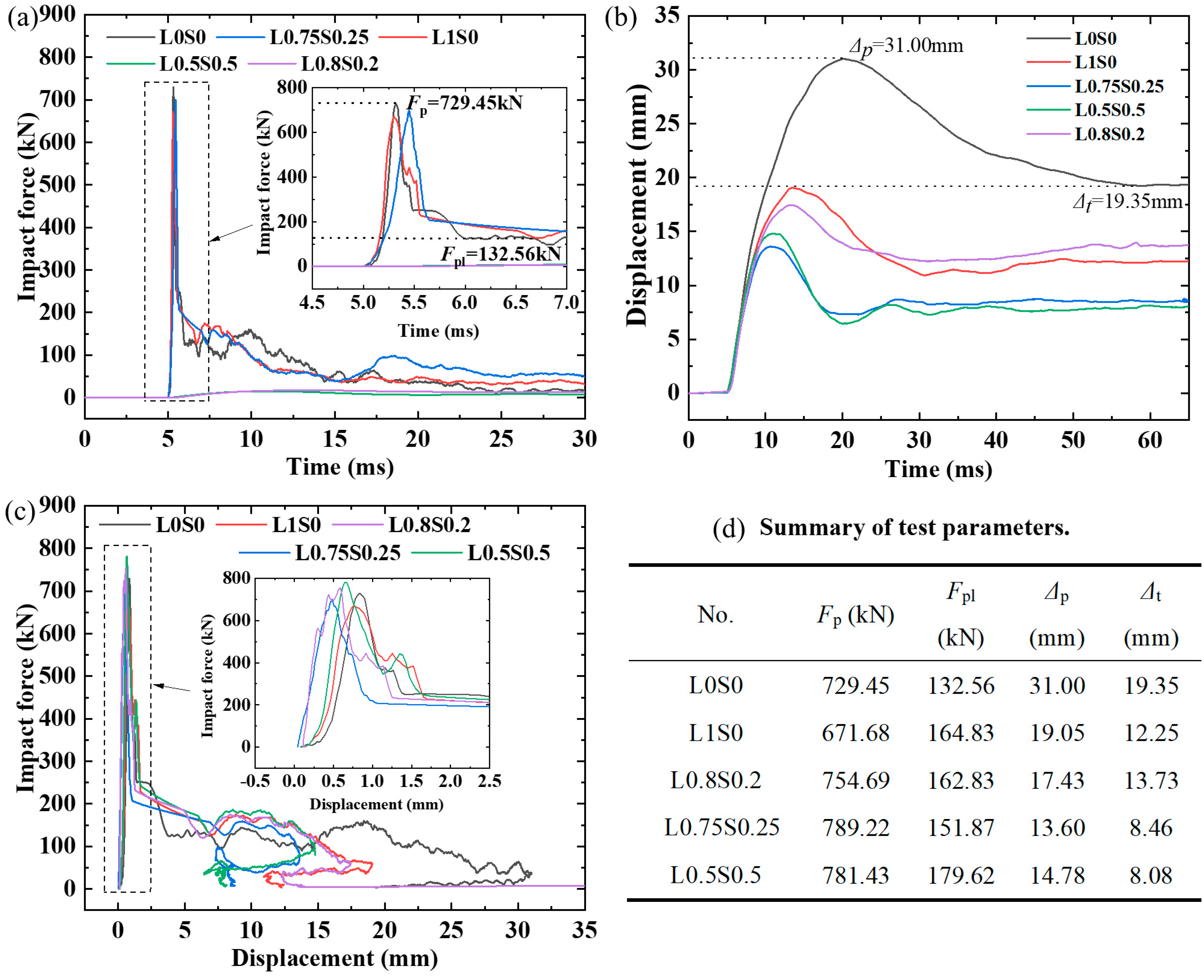
For the tested corroded reinforced concrete simply supported beams, the shapes of their load–time history and midspan displacement–time history curves are roughly similar. As shown in Figure 7a, analysis of the load–time history diagram reveals that the impact load is divided into three stages: the peak stage, the plateau stage, and the unloading stage. Peak stage: Upon impact initiation, the drop hammer contacts the upper surface of the beam, imparting downward acceleration to the beam. The impact force rapidly reaches the first instantaneous peak, defined as , within an extremely short time. Due to the inconsistent velocities of the beam and the drop hammer, a tendency for separation emerges, causing the load to decrease rapidly. Plateau stage: The downward velocities of the beam and the drop hammer become more consistent, and the impact force stabilizes at an approximately constant level; the representative plateau force is denoted as , as illustrated in the inset of Figure 7a. Unloading stage: Since the energy dissipated through beam deformation is insufficient to consume all the potential energy of the hammer, the midspan displacement of the beam reaches its maximum. Subsequently, due to the recovery of elastic deformation and the release of elastic strain energy in the beam, both the beam and the drop hammer begin to move upward, and the impact force decreases until the drop hammer separates from the beam.
Figure 7.
(a) Impact force–time history curve; (b) Mid-span deflection–time history curve; (c) Test beam mid-span displacement–load curve, and (d) Summary of test parameters.
As shown in Figure 7a, the impact force–time history curves of all specimens exhibit an instantaneous peak, which appears in the initial phase of the impact curve. This peak can be defined as the main impact force waveform, with a duration ranging from 0.9 ms to 1.7 ms. Among them, plain concrete beams show a longer waveform duration, single fiber-reinforced concrete beams have a shorter duration, and HSFRC beams (L0.75S0.25 and L0.5S0.5) exhibit the shortest duration. This is because the rising segment of the main impact force waveform is related to the contact stiffness at the impact point: the higher the contact stiffness, the shorter the duration of the main impact force waveform. HSFRC beams have higher stiffness, thus their main waveform duration is shorter. Furthermore, due to the strong ability of short fibers to control microcracks, which effectively suppresses the formation of pores and cracks and slows down the corrosion rate of steel reinforcement [49], specimens L0.75S0.25 and L0.5S0.5 exhibit lower corrosion rates. As a result, the structural damage caused by corrosion is relatively minor, and the flexural stiffness of these beams is greater compared to other HSFRC beams. Secondly, the plausible explanation for this is that the long fibers can be treated as arbitrary boundaries to the short fibers, which can moderately confine the alignment of the short fibers, as well as reduce the clustering of short fibers, thereby preventing stress concentration [50].
As shown in Figure 7b, the maximum deflection of HSFRC gradient beams is significantly lower than that of plain concrete beams. As the kinetic energy of the beam and drop hammer is converted into the elastic strain energy of the beam, the beam displacement reaches a peak, denoted as Δp (see Figure 7d for details). There is a delay of 5 ms to 15 ms between the displacement peak and the load peak: for HSFRC beams, the delay is within 7 ms, and after reaching the displacement peak, the displacement rapidly drops to the residual displacement within 10 ms, with an interval of 3.7 mm to 6.8 mm between the residual displacement and the displacement peak. Among them, HSFRC beams (L0.8S0.2, L0.75S0.25, and L0.5S0.5) show smaller displacement intervals. In contrast, the delay for plain concrete beams without fibers is 15 ms, and after reaching the displacement peak, the time to drop to the residual displacement exceeds 40 ms, with a displacement interval of 11.65 mm. Subsequently, the beam and hammer undergo regular longitudinal harmonic vibrations, and eventually, the kinetic energy diminishes to zero under damping effects, at which point the residual displacement of the beam is denoted as Δt (see Figure 7d for details).
As illustrated in Figure 7c, which depicts the mid-span displacement–load curves, HSFRC beams exhibit more than a 10% enhancement in peak load-bearing capacity. Furthermore, while maintaining a constant total fiber volume fraction, the mechanical properties of the concrete demonstrate a non-monotonic trend, characterized by an initial improvement followed by deterioration, as the proportion of short fibers increases [51]. There are two key stages in the curves shown in Figure 7c: the peak stage and the plateau stage. In the peak stage, the midspan displacement of the beam specimen is still small, approximately 1 mm. This stage is characterized by a rapid increase in load with relatively small displacement changes. After the load reaches the peak, the beam specimen enters the plateau stage, where displacement begins to develop rapidly and the concrete starts to undergo plastic deformation. In the L0S0 specimen, the displacement in the plateau stage is relatively short, but after the plateau, the displacement continues to increase. Compared with the plain concrete beam L0S0, steel fiber-reinforced beam specimens exhibit a longer plateau displacement; however, after the plateau, the displacement decreases rapidly and rebounds quickly as the impact force diminishes. This indicates that during impact loading, HSFRC beams exhibit a relatively slower decrease in displacement and a faster recovery, with smaller residual strains, reflecting their higher flexural stiffness.
3.4. Energy Dissipation and Dynamic Response of Gradient Beams
The ratios of energy dissipation to input energy of beams under various working conditions are detailed in Table 5. The energy dissipation value Ep of the beam was calculated based on the integral area of the midspan displacement–load curve, which approximately reflects the actual energy dissipation state. The input kinetic energy Ek of the impact load was calculated from the gravitational potential energy at the hammer release position, i.e.,. According to the law of energy conservation, the value of Ep/Ek should be between 0 and 1. It is known that impact energy is primarily consumed by the elastic deformation energy stored in the beam itself, crack propagation, and plastic deformation. Among these, the latter two manifest as irreversible plastic damage, which poses greater hazards to the serviceability and integrity of the beam structure, while the former can attenuate through regular harmonic vibrations of the beam until it stabilizes. As shown in Table 5, the energy input–output ratios of all beams range from 0.70 to 0.93, with L0.75S0.25 exhibiting the smallest ratio of 0.70. Post-failure images of the specimens reveal that, except for L0.75S0.25, severe concrete spalling occurred near the impact points of other beams, with extensive concrete peeling and the formation of wide 45° diagonal cracks from the impact points to the beam bottoms.
Table 5.
The ratio of the absorbed energy to the input energy of each beam.
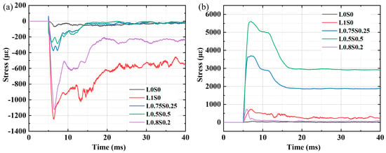
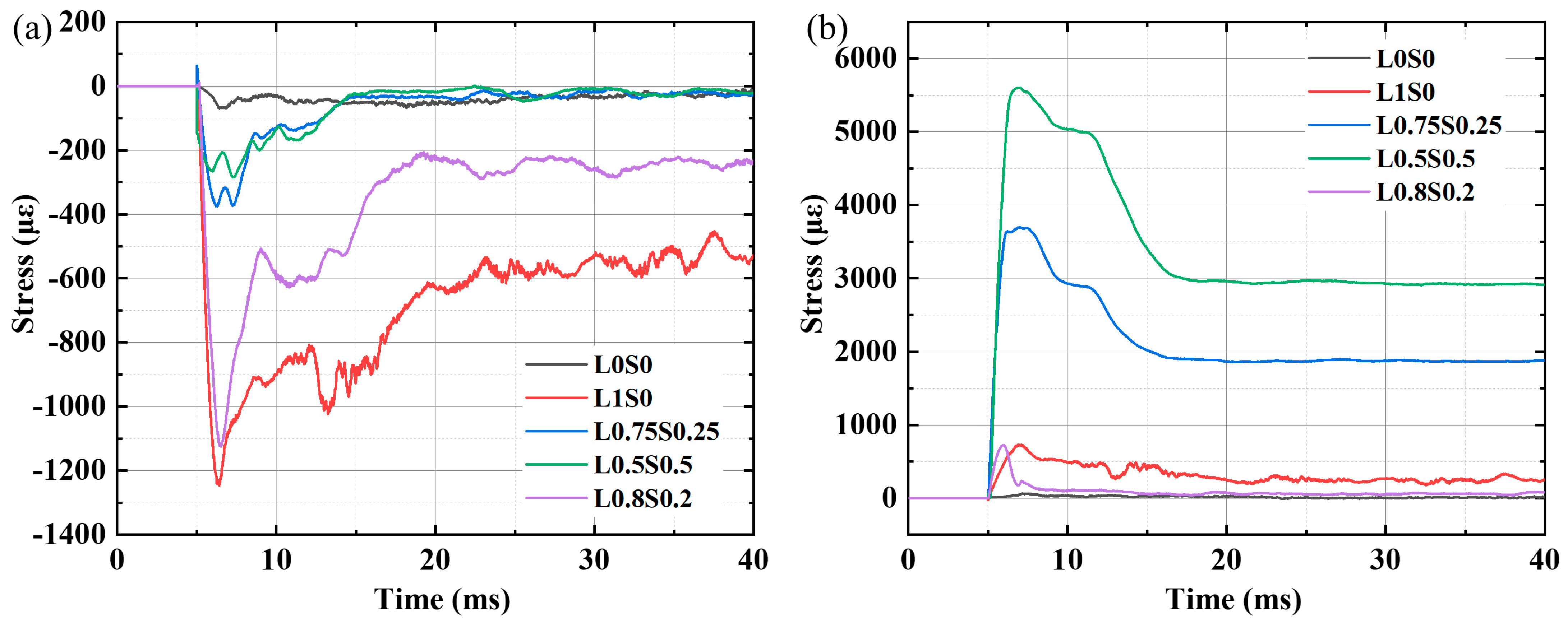
As described in Figure 3a, vertical strain gauges arranged in the flexural–shear segments and at the support ends of the beams captured the free vibration of the test beams after impact, with the resulting curves shown in Figure 8a,b. The amplitudes of different concrete beams varied; however, due to the influence of random crack distribution on strain gauge positions, this study only analyzed the harmonic vibration periods and amplitudes induced by the elastic deformation energy of the beams. HSFRC beams (L0.8S0.2, L0.75S0.25 and L0.5S0.5) exhibited amplitudes of approximately 1000 με, with peak impact forces ranging from 699 kN to 754 kN. These beams showed small peak displacement, small residual displacement, and a small difference between the two, confirming their high impact-resistant stiffness. Additionally, the small gap between wave crests and troughs indicated that elastic strain could be uniformly released through small-range periodic harmonic motion after impact loading. In contrast, L1S0 exhibited the largest amplitude of 4000 με, with a gap of up to 3500 με from the trough, indicating highly uneven release of elastic strain energy. As shown in Figure 7d, its maximum displacement Δp reached 19.05 mm and residual displacement Δt was 12.25 mm, with a large difference between them, reflecting severe beam deformation and poor overall structural stability.
Figure 8.
(a) Strain diagram of beam support end; (b) Strain diagram of beam bending shear end.
Due to the varying mechanical effects of steel fibers with different sizes on concrete beams, increasing the content of long fibers positively enhances energy dissipation under impact loading. A higher long-fiber content enhances the ability of steel fiber-reinforced concrete gradient beams to dissipate energy through plastic deformation, yet at the expense of reduced structural integrity. In contrast, increasing the short-fiber content effectively reduces the extent of plastic deformation for energy dissipation, thereby better preserving the structural integrity of the beam [52]. However, owing to their larger specific surface area and stronger mutual interactions, short fibers tend to form localized fiber-rich zones and interfacial weak regions [53]. Such structural inhomogeneity can easily induce stress concentration and accelerate the coalescence of microcracks during loading, hindering the full utilization of fiber bridging and energy dissipation mechanisms. Consequently, the mechanical performance shifts from enhancement to degradation [50]. Among all specimens, L0.75S0.25 exhibited the smallest maximum displacement and residual displacement, as well as the lowest energy dissipation ratio, indicating less plastic damage from energy absorption and more energy dissipation through elastic deformation after impact. This was specifically reflected in the dissipation of stored elastic deformation energy through free vibration after reaching the peak displacement. The toughness and energy absorption increased by more than 164% compared to those of plain concrete. With the addition of fibers, the energy absorption parameters significantly increase, indicating that toughness and residual bearing capacity have been enhanced [50,54]. However, L1S0 displayed higher energy dissipation, suggesting enhanced energy dissipation through fiber pull-out mechanisms.
3.5. Equivalent Impact Bearing Capacity of Gradient Beams
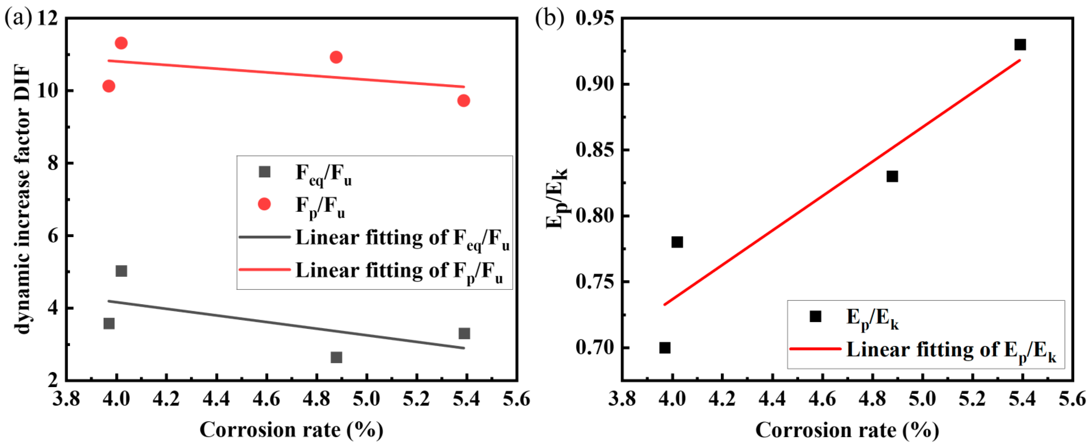
To characterize the influence of various factors on the impact performance of concrete beams, Wei et al. [18] defined the impact performance of concrete beams using the Dynamic Increase Factor (DIF). The calculation methods include the ratio of equivalent impact bearing capacity to static ultimate bearing capacity Feq/Fu, and the ratio of peak impact force to static ultimate bearing capacity Fp/Fu. During impact tests, since the impact effect manifests as a continuously changing load response, the equivalent impact bearing capacity (Feq) is defined as the force exerted on the beam based on impact energy to establish an equivalent relationship with the static bearing capacity of the beam. Its calculation method is given in Equation (3).
where Ea is the energy absorbed by the member during impact; δ is the residual deformation at the impact location of the member. The equivalent impact bearing capacity Feq of each specimen is calculated as shown in Table 6. Ea is taken as the impact energy dissipation value under each working condition, δ is taken as the final midspan residual displacement Δt of each specimen, and the static load data is shown in Figure 4c. As shown in Table 6, under the test conditions, the peak impact force Fp of the specimens reaches 9–11 times the static ultimate bearing capacity, and the equivalent impact bearing capacity of HSFRC gradient beams reaches 2.6–3.6 times the static ultimate bearing capacity. The reason for the relatively large equivalent impact bearing capacity in this test is that HSFRC increases the peak impact force of the beam, while its influence on the static ultimate shear bearing capacity is minimal. Consequently, the calculated equivalent impact bearing capacity is relatively large. Furthermore, the elastoplastic stress–strain relationship of concrete beams is related not only to the concrete itself but also to the loading time. Steel bars and HSFRC exhibit increased strength under rapid loading, which further amplifies the impact load.
Table 6.
The Feq value of each specimen and the comparison between the static and dynamic tests.
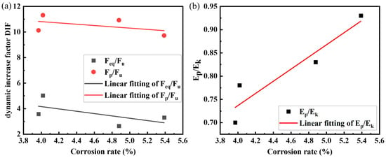
As shown in Figure 9a, the dynamic increase factor (DIF) of impact load for concrete beams shows a decreasing trend with increasing corrosion rates of different specimens, indicating that the residual bearing capacity of the beam after impact loading decreases as the corrosion rate increases [55,56]. This suggests that in practical engineering applications, for structural components susceptible to impact loads, it is not only necessary to enhance their impact resistance by strengthening the cross-section but also to improve their corrosion resistance through certain measures. As shown in Table 6, the HSFRC beams with short fiber contents of 0.75% and 0.25% exhibit lower corrosion rates, indicating their stronger corrosion resistance. This is attributed to the ability of short fibers to effectively control microcracks, suppress the formation of pores and cracks, and slow down the corrosion rate of steel reinforcement, thereby resulting in higher residual load-bearing capacity after impact loading [57]. This indicates that a low proportion of short fibers plays a crucial role in optimizing and controlling the strength performance of concrete [51]. Figure 9b illustrates the relationship between impact load energy dissipation level and corrosion rate of concrete beams under different corrosion rates. The Ep/Ek values of the test beams show an increasing trend with the increase in longitudinal bar corrosion rate [55,56]. It should be emphasized that this increase in Ep/Ek primarily reflects more severe damage and irreversible plastic deformation (e.g., cracking, spalling, and steel yielding) induced by corrosion, rather than an improvement in impact resistance. Dai [55] confirmed this conclusion in the high corrosion rate range (5–18%), while Yang [56] validated it in the low corrosion rate range (below 1%). This study investigates the relationship between corrosion rate and energy dissipation level of reinforced concrete gradient beams with hybrid steel fibers in the 3–5% corrosion range. According to the data in Table 6, the HSFRC gradient beam L0.75S0.25 with 0.25% short fiber content and 0.5% long fiber content exhibits the lowest steel bar corrosion rate. Due to its low corrosion rate, this fiber content ratio results in minimal energy dissipation through deformation, cracking, and concrete spalling, and maximal energy dissipation through elastic deformation. Therefore, the structural integrity under impact loading is better. The above results indicate that, under the condition of a constant total fiber volume fraction, rationally adjusting the proportion and gradation of long and short fibers is a key design factor for fully exploiting the reinforcing efficiency of fibers and achieving superior mechanical performance.
Figure 9.
(a) Relationship between dynamic increase factor DIF and corrosion rate, and (b) Relationship between energy dissipation and corrosion rate.
The combined effect of fiber content and corrosion level on impact resistance can be interpreted as a coupling mechanism between microcrack control and reinforcement degradation. As the corrosion rate increases, the reduction in effective cross-sectional area of longitudinal reinforcement and the development of rust-induced cracks weaken the structural integrity and stiffness of the beam. However, hybrid steel fibers mitigate this deterioration by bridging corrosion-induced microcracks and restraining crack propagation under impact loading. When an appropriate proportion of short and long fibers is adopted (e.g., L0.75S0.25), the synergistic multiscale reinforcement mechanism becomes more effective in compensating for corrosion-induced damage, resulting in relatively higher residual impact capacity and lower displacement. Conversely, when the fiber proportion is suboptimal, the improvement effect diminishes, and the impact resistance becomes more sensitive to corrosion progression.
It should be noted that the accelerated corrosion method adopted in this study may not fully reproduce the long-term cracking characteristics of natural corrosion. However, the purpose of the accelerated technique was to achieve controlled corrosion levels within a reasonable timeframe for systematic performance evaluation. Although differences in crack morphology may exist, the fundamental mechanisms of reinforcement cross-sectional loss and corrosion-induced expansion remain comparable. Therefore, the comparative trends and interaction effects identified herein are considered representative for engineering assessment.
3.6. Relationship Between Maximum Midspan Strain and Energy Consumption
Impact force is characterized by the application of an extremely high peak load within a short time. Concrete beam specimens designed based on static criteria are relatively conservative; thus, components should be allowed to undergo large deformations to dissipate impact energy. For this purpose, a maximum displacement can be adopted as the control index for the allowable displacement in beam design. Specifically, if the maximum displacement of the test beam exceeds , the design is considered unsafe and requires cross-sectional modification. Based on experimental results, Kishi et al. [58] proposed an empirical formula for estimating the maximum deflection of simply supported beams under drop-weight impact:
where is the maximum deflection of the beam; pusd is the static bearing capacity; Ekd is the kinetic energy of the drop hammer; and α is the proportional coefficient derived from fitting experimental data. In Kishi’s [58] experiments, α = 0.6; in Zhao Debo’s [59] experiments, α = 0.585; and in Tachibana’s [60] experiments, α = 0.71. However, the beams in the former studies contained no steel fibers. The calculated α values in this experiment are presented in Table 7. As shown in the table, compared with single fiber-reinforced concrete gradient beams, the proportional coefficient α of hybrid steel fiber gradient beams decreases by 9.1–29.5%, indicating that hybrid steel fiber gradient beams can effectively reduce the maximum displacement under peak impact load and improve the safety of structural design.
Table 7.
Maximum displacement of the test beam and proportionality factor α.
With the extension of energization time and continuous supplementation of chloride ions, pores and cracks form in concrete under rust expansion stress. These pores and cracks accumulate chloride ions, accelerating steel bar corrosion. According to the data in Table 7, the HSFRC gradient beam with a short fiber content of 0.25% and a long fiber content of 0.75% exhibits the smallest deflection. This may also be attributed to its lowest steel corrosion rate, which results in minimal microstructural changes. Consequently, fewer pores and microcracks develop in the early stage, enabling specimen L0.75S0.25 to demonstrate superior impact resistance [61].
It should be acknowledged that the accelerated corrosion method adopted in this study may not fully replicate the long-term electrochemical processes and cracking patterns associated with natural corrosion under field conditions. Accelerated techniques can lead to differences in rust distribution, cracking morphology, and corrosion kinetics due to the imposed current density. However, the primary objective of this study was to achieve controlled corrosion levels and to evaluate the structural response at specified corrosion rates rather than to simulate the exact time-dependent corrosion process. The mechanical degradation of the reinforcement cross-sectional area and the expansion-induced cracking mechanisms remain fundamentally similar in both accelerated and natural corrosion scenarios. Therefore, while differences in crack patterns may exist, the comparative trends and the coupled interaction between corrosion level and hybrid fiber reinforcement identified in this study are considered representative for engineering assessment. Further long-term natural exposure studies are recommended to validate the findings under field conditions.
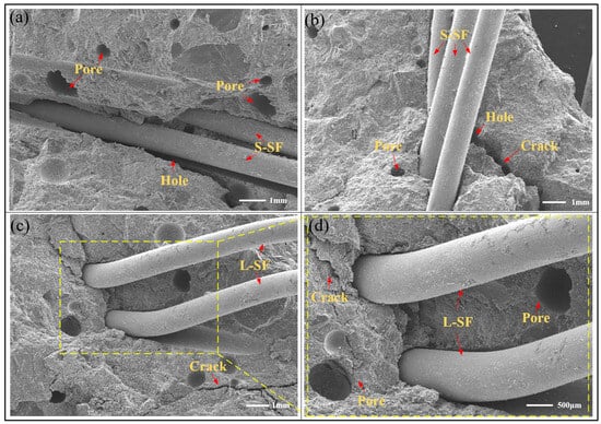
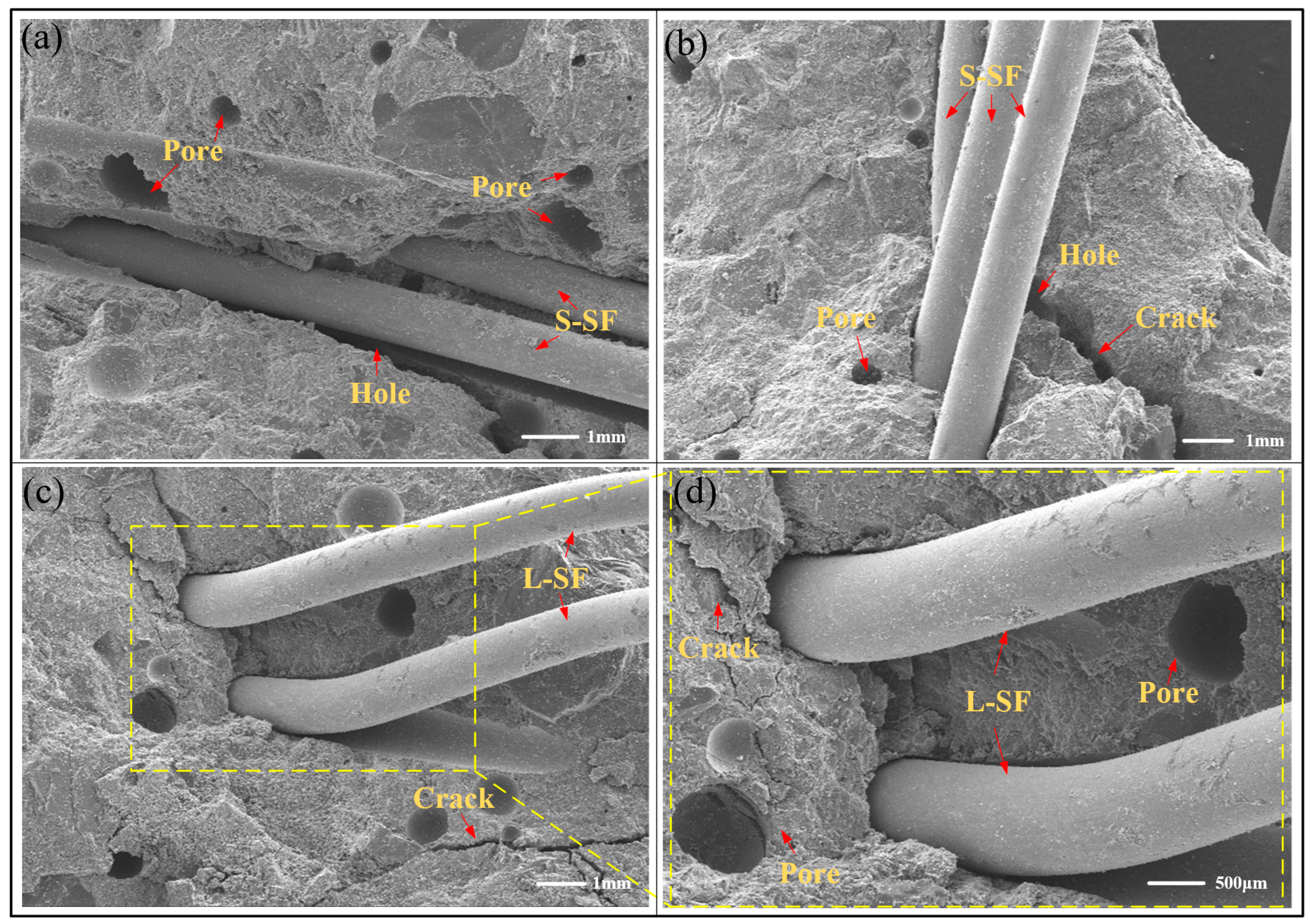
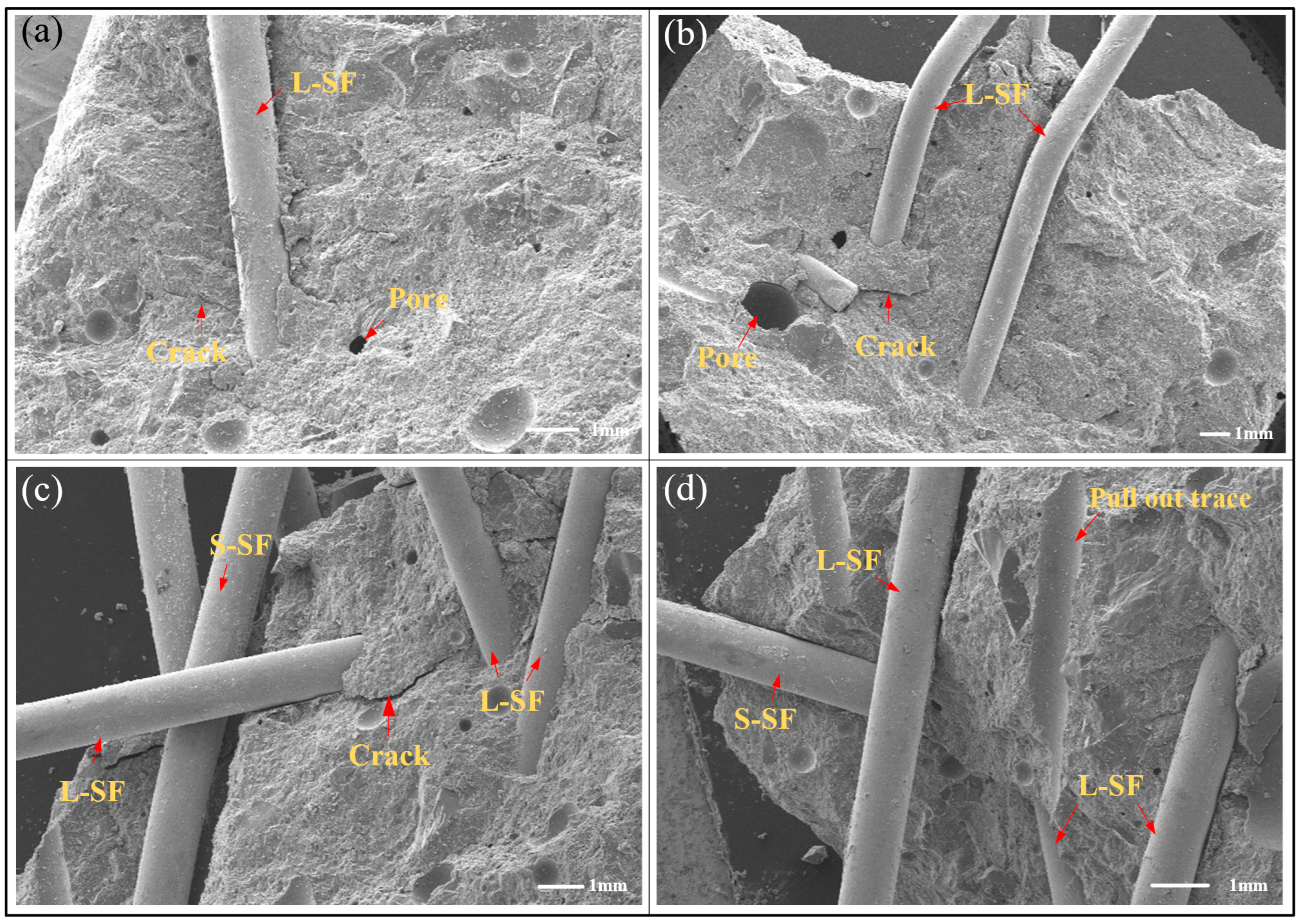
Under the condition of a constant total fiber volume fraction, the impact resistance of the concrete initially improves and then deteriorates as the proportion of short fibers increases. This trend essentially reflects the evolution of the multi-scale synergistic enhancement effect between long and short fibers, transitioning from full utilization to gradual ineffectiveness [51]. When the proportion of long fibers is relatively high, the lower fiber number density per unit volume results in larger interfiber spacing. Their reinforcing effect is thus primarily manifested in the bridging and retardation of macrocrack propagation, while their ability to constrain the initiation of early-stage microcracks is limited. This is corroborated by the observations in Figure 10, which show wider crack widths and a smaller number of effectively bridging fibers. With a moderate increase in the short fiber proportion, the number of short fibers increases significantly, effectively filling the matrix regions between long fibers. This facilitates a rational division of labor among fibers at different scales, establishing a more continuous and dense multi-scale fiber reinforcement network [49]. As shown in Figure 11, the fiber distribution within the matrix becomes more uniform, the fiber–matrix interfacial bonding becomes tighter, and the crack propagation paths become more tortuous. The number and width of microcracks are markedly reduced, thereby promoting more effective stress transfer and enhancing the mechanical performance.
Figure 10.
SEM results: (a) L0.5S0.5; (b) L0.5S0.5; (c) L1S0 and (d) L1S0.
Figure 11.
SEM results: (a) L1S0; (b) L0.8S0.2; (c) L0.75S0.25 and (d) L0.75S0.25.
However, when the short fiber proportion is further increased, their dispersibility declines noticeably due to their larger specific surface area and enhanced mutual interactions, leading to a deterioration in the rheological properties of the fresh mixture and the occurrence of local fiber clustering [53]. As shown in Figure 10a,b, fiber-rich zones and interfacial defects can be observed. These structural inhomogeneities are prone to induce stress concentration during loading and promote the rapid coalescence of cracks [40], hindering the full exertion of fiber bridging and energy dissipation mechanisms. Ultimately, this causes the mechanical performance to shift from enhancement to decline.
It should be noted that the present study is based on small-scale beam specimens, and potential size effects may influence the absolute structural response in full-scale members. In larger structures, variations in crack development patterns, stress redistribution, and strain-rate sensitivity may occur due to geometric scaling. Nevertheless, the fundamental mechanisms identified in this study—particularly the multiscale crack-bridging effect of hybrid fibers and the coupled interaction between fiber gradation and corrosion-induced degradation—are primarily governed by material behavior rather than structural dimensions. Therefore, while quantitative performance indicators may vary with size, the observed trends and optimization principles of hybrid fiber proportion are expected to remain applicable to full-scale structural members. Further full-scale experimental or numerical investigations are recommended to validate the scalability of the present findings.
4. Conclusions
This work investigated the performance degradation of reinforced concrete gradient beams with different sizes and contents of steel fibers under the same corrosion conditions through impact tests and static tests on HSFRC gradient beams. The main conclusions are as follows:
- (1)
- The addition of steel fibers significantly improves the impact resistance of reinforced concrete gradient beams, with up to a 2.5 times enhancement. Steel fibers help maintain structural integrity by reducing concrete spalling in the tensile zone, increasing beam stiffness, and limiting deflection and strain, enabling faster recovery after impact.
- (2)
- HSFRC gradient beams exhibit high impact resistance and only suffer minor flexural damage. Compared to beams with single long fibers, HSFRC beams demonstrate a reduction in maximum and residual deflections ranging from 9.1% to 29.5%, along with approximately 16% higher peak impact force, attributed to the enhanced material modulus under high loading rates.
- (3)
- Within the corrosion range of 3% to 5%, the equivalent impact capacity exhibited a negative correlation with the corrosion rate. In contrast, Ep/Ek increases with corrosion rate, which mainly reflects intensified damage and plastic deformation. Although more energy is dissipated, the residual bearing capacity and structural integrity are reduced. Higher corrosion rates lead to decreased structural integrity, making beams more prone to cracking and concrete spalling under impact loading, thereby significantly reducing the residual bearing capacity.
- (4)
- The combined effect of fiber proportion and reinforcement corrosion governs the impact resistance of HSFRC gradient beams. Within the investigated corrosion range (3–5%), a hybrid fiber ratio of 0.75% long fibers and 0.25% short fibers provides the most effective compensation for corrosion-induced degradation, resulting in reduced displacement and improved residual impact capacity. Optimizing the long–short fiber ratio is therefore critical for maintaining impact performance under corrosive conditions.
- (5)
- From an engineering perspective, a hybrid configuration with a higher proportion of long fibers is recommended for reinforced concrete members exposed to moderate corrosion and potential impact loading. Fiber dosage should be optimized considering workability, durability requirements, and economic efficiency.
Author Contributions
Conceptualization, Z.G.; Methodology, Z.G.; Software, D.L.; Validation, D.L.; Investigation, Y.W.; Resources, X.Z. and G.G.; Data curation, Y.S.; Writing—original draft, S.L.; Writing—review & editing, S.L.; Supervision, X.Z.; Project administration, G.G.; Funding acquisition, G.G. All authors have read and agreed to the published version of the manuscript.
Funding
This work was financially supported by the Continuation Funding Project of the Outstanding Youth Foundation of Zhejiang Provincial Natural Science Foundation (NO. LRG25E080002), National Natural Science Foundations of China (NO. 52378271), and China Postdoctoral Science Foundation (NO. 2024M762913). This work was supported by the Engineering Research Center of the Ministry of Education for Renewable Energy Infrastructure Construction Technology.
Data Availability Statement
Data is contained within the article. Further inquiries can be directed to the corresponding author.
Conflicts of Interest
Author Yezhe Shao was employed by the company China United Engineering Corporation. Author Xuefeng Zhang was employed by the company Zhejiang University of Technology Engineering Design Group Co., Ltd. The remaining authors declare that the research was conducted in the absence of any commercial or financial relationships that could be construed as a potential conflict of interest.
References
- Kazemi, F.; Shafighfard, T.; Yoo, D.Y. Data-Driven Modeling of Mechanical Properties of Fiber-Reinforced Concrete: A Critical Review. Arch. Comput. Methods Eng. 2024, 31, 2049–2078. [Google Scholar] [CrossRef] [Scilit]
- Dong, J.; Liu, Y.; Yuan, S.; Li, K.; Zhang, F.; Guan, Z.; Chai, H.; Wang, Q. Mechanical behavior and impact resistance of rubberized concrete enhanced by basalt fiber-epoxy resin composite. Constr. Build. Mater. 2024, 435, 136836. [Google Scholar] [CrossRef] [Scilit]
- Li, L.; Zong, M.; Li, F.; Wu, J.; Wang, D.; Du, X. Experimental study on the dynamic compression behaviors of steel-polyethylene hybrid fiber reinforced engineered cementitious composites under combined static-dynamic loading. Constr. Build. Mater. 2025, 477, 141234. [Google Scholar] [CrossRef] [Scilit]
- Wu, Z.; Shi, C.; He, W.; Wang, D. Static and dynamic compressive properties of ultra-high performance concrete (UHPC) with hybrid steel fiber reinforcements. Cem. Concr. Compos. 2017, 79, 148–157. [Google Scholar] [CrossRef] [Scilit]
- Shabakhty, N.; Karimi, H.R.; Bakhtiary, A.Y. Statistical evaluation of fracture and mechanical performance of engineered cementitious composites (ECC), containing different percentages of glass, polypropylene, polyvinyl-alcohol fibers, and fly ash. Constr. Build. Mater. 2024, 417, 135247. [Google Scholar] [CrossRef] [Scilit]
- Wu, Z.; Shi, C.; He, W.; Wu, L. Effects of steel fiber content and shape on mechanical properties of ultra high performance concrete. Constr. Build. Mater. 2016, 103, 8–14. [Google Scholar] [CrossRef] [Scilit]
- Yoo, D.Y.; Yoon, Y. Structural performance of ultra-high-performance concrete beams with different steel fibers. Eng. Struct. 2015, 102, 409–423. [Google Scholar] [CrossRef] [Scilit]
- Zhang, H.; He, B.; Chen, W.; Ai, J.; Zhu, X.; Jiang, Z. Investigating the influence of fibre type and content on the toughness and ductility of geopolymer mortar with acoustic emission technology. Cem. Concr. Compos. 2024, 147, 105434. [Google Scholar] [CrossRef] [Scilit]
- Xian, G.; Zhou, P.; Li, C.; Dong, S.; Du, H.; Tian, J.; Guo, R.; Peng, Z.; Zhang, Z.; He, T. Mechanical properties evaluation of glass fiber reinforced thermoplastic composite plate under combined bending loading and water immersion. Constr. Build. Mater. 2024, 440, 137470. [Google Scholar] [CrossRef] [Scilit]
- Harle, S.M. Durability and long-term performance of fiber reinforced polymer (FRP) composites: A review. Structures 2024, 60, 105881. [Google Scholar] [CrossRef] [Scilit]
- Qiang, Y.; Li, L.; He, Z. Test research on the steel fiber reinforced concrete against the acid environment. Concrete 2011, 6, 41–42. [Google Scholar]
- Zhao, J.; Li, H.; Gao, D. Mechanical Performances of Steel Fiber and Steel Fiber Reinforced Concrete after Corrosion. J. Build. Mater. 2015, 18, 409–414. [Google Scholar]
- O’Brien, C.; McBride, A.; Zaghi, A.E.; Burke, K.A.; Hill, A. Mechanical Behavior of Stainless Steel Fiber-Reinforced Composites Exposed to Accelerated Corrosion. Materials 2017, 10, 772. [Google Scholar] [CrossRef] [Scilit]
- Frazão, C.; Barros, J.; Camões, A.; Alves, A.C.; Rocha, L. Corrosion effects on pullout behavior of hooked steel fibers in self-compacting concrete. Cem. Concr. Res. 2016, 79, 112–122. [Google Scholar] [CrossRef] [Scilit]
- Ngo, T.T.; Tran, N.T.; Kim, D.J.; Pham, T.C. Effects of corrosion level and inhibitor on pullout behavior of deformed steel fiber embedded in high performance concrete. Constr. Build. Mater. 2021, 280, 122449. [Google Scholar] [CrossRef] [Scilit]
- Yoo, D.Y.; Jang, Y.S.; Oh, T.; Banthia, N. Use of engineered steel fibers as reinforcements in ultra-high-performance concrete considering corrosion effect. Cem. Concr. Compos. 2022, 133, 104692. [Google Scholar] [CrossRef] [Scilit]
- Tamai, H.; Sonoda, Y.; Bolander, J.E. Impact resistance of RC beams with reinforcement corrosion: Experimental observations. Constr. Build. Mater. 2020, 263, 120638. [Google Scholar] [CrossRef] [Scilit]
- Wei, J.; Li, J.; Wu, C.; Liu, Z.; Li, J. Hybrid fibre reinforced ultra-high performance concrete beams under static and impact loads. Eng. Struct. 2021, 245, 112921. [Google Scholar] [CrossRef] [Scilit]
- Liu, Y.; Wei, Y. Drop-Weight Impact Resistance of Ultrahigh-Performance Concrete and the Corresponding Statistical Analysis. J. Mater. Civ. Eng. 2021, 34, 04021409. [Google Scholar] [CrossRef] [Scilit]
- Bakhshi, M.; Valente, I.; Ramezansefat, H. New model for evaluating the impact response of steel fiber reinforced concrete subjected to the repeated drop-weight. Constr. Build. Mater. 2024, 449, 138459. [Google Scholar] [CrossRef] [Scilit]
- Li, L.; Wang, Z.; Wu, J.; Du, X.; Wang, H.; Liu, W. Comparative analysis of dynamic mechanical properties of steel fiber reinforced concrete under ambient temperature and after exposure to high temperatures. Case Stud. Constr. Mater. 2024, 20, e02778. [Google Scholar] [CrossRef] [Scilit]
- Pham, T. Fibre-reinforced concrete: State-of-the-art-review on bridging mechanism, mechanical properties, durability, and eco-economic analysis. Case Stud. Constr. Mater. 2025, 22, e04574. [Google Scholar] [CrossRef] [Scilit]
- Mangat, P.S.; Elgarf, M.S. Flexural strength of concrete beams with corroding reinforcement. ACI Struct. J. 1999, 96, 149–158. [Google Scholar] [CrossRef] [Scilit]
- Hariche, L.; Ballim, Y.; Bouhicha, M.; Kenai, S. Effects of reinforcement configuration and sustained load on the behaviour of reinforced concrete beams affected by reinforcing steel corrosion. Cem. Concr. Compos. 2012, 34, 1202–1209. [Google Scholar] [CrossRef] [Scilit]
- Li, H.; Li, B.; Jin, R.; Li, S.; Yu, J. Effects of sustained loading and corrosion on the performance of reinforced concrete beams. Constr. Build. Mater. 2018, 169, 179–187. [Google Scholar] [CrossRef] [Scilit]
- Fu, C.; Huang, J.; Dong, Z.; Song, C.; Zhang, Y. Shear behavior of reinforced concrete beams subjected to accelerated non-uniform corrosion. Eng. Struct. 2023, 286, 116081. [Google Scholar] [CrossRef] [Scilit]
- Tapan, M.; Aboutaha, R.S. Effect of steel corrosion and loss of concrete cover on strength of deteriorated RC columns. Constr. Build. Mater. 2011, 25, 2596–2603. [Google Scholar] [CrossRef] [Scilit]
- Vidal, T.; Castel, A.; Francois, R. Corrosion process and structural performance of a 17 year old reinforced concrete beam stored in chloride environment. Cem. Concr. Res. 2007, 37, 1551–1561. [Google Scholar] [CrossRef] [Scilit]
- François, R.; Khan, I.; Dang, V.H. Impact of corrosion on mechanical properties of steel embedded in 27-year-old corroded reinforced concrete beams. Mater. Struct. 2013, 46, 899–910. [Google Scholar] [CrossRef] [Scilit]
- Dai, M.; Yang, O.; Xiao, Y.; Li, F. Influence of longitudinal bar corrosion on impact behavior of RC beams. Mater. Struct. 2016, 49, 3579–3589. [Google Scholar] [CrossRef] [Scilit]
- Ou, Y.; Nguyen, N.D. Influences of location of reinforcement corrosion on seismic performance of corroded reinforced concrete beams. Eng. Struct. 2016, 126, 210–223. [Google Scholar] [CrossRef] [Scilit]
- Li, Q.; Zheng, D.; He, Q.; Fu, C.; Jin, X. Effects of Reinforcement Corrosion and Sustained Load on Mechanical Behavior of Reinforced Concrete Columns. Materials 2022, 15, 3590. [Google Scholar] [CrossRef] [Scilit] [PubMed]
- Cabrera, J.G. Deterioration of concrete due to reinforcement steel corrosion. Cem. Concr. Compos. 1996, 18, 47–59. [Google Scholar] [CrossRef] [Scilit]
- Du, Y.; Cullen, M.; Li, C. Structural performance of RC beams under simultaneous loading and reinforcement corrosion. Constr. Build. Mater. 2013, 38, 472–481. [Google Scholar] [CrossRef] [Scilit]
- Ramkumar, K.B.; Rajkumar, P.R. Impact of hybrid steel fibres on fresh and mechanical properties of Self-compacting concrete. Case Stud. Constr. Mater. 2022, 17, e01274. [Google Scholar] [CrossRef] [Scilit]
- Ramkumar, K.B.; Rajkumar, P.R.; Gunasekaran, K. Performance of hybrid steel fiber-reinforced self-compacting concrete RC beam under flexure. Eng. Sci. Technol. Int. J. 2023, 42, 101432. [Google Scholar]
- Shao, R.; Wu, C.; Li, J.; Liu, Z. Investigation on the mechanical characteristics of multiscale mono/hybrid steel fibre-reinforced dry UHPC. Cem. Concr. Compos. 2022, 133, 104681. [Google Scholar] [CrossRef] [Scilit]
- Wang, Q.; Liang, L.; Shi, Q. Mechanical properties and constitutive model of ultra-high performance concrete with hybrid steel fiber under axial tension. Acta Mater. Compos. Sin. 2024, 41, 383–394. (In Chinese) [Google Scholar]
- Su, J.; Lin, Y.; Chen, B.; Huang, Q. Hydrid effects of steel fibers on the uniaxial tensile properties of ultra-high performance concrete. J. Nanchang Univ. (Eng. Technol.) 2019, 41, 358–364. (In Chinese) [Google Scholar]
- GB/T 50081-2019; Standard for Test Methods of Concrete Physical and Mechanical Properties. Architecture and Building Press: Beijing, China, 2019.
- Zhu, Y.; Zhu, X.; Ge, Y.; Wu, S.; Zhu, X. Evaluation of reinforcement corrosion in reinforced concrete member by half-cell potential method. Hydro Sci. Eng. 2003, 4, 41–44. [Google Scholar]
- Soleymani, H.R.; Ismail, M.E. Comparing corrosion measurement methods to assess the corrosion activity of laboratory OPC and HPC concrete specimens. Cem. Concr. Res. 2004, 34, 2037–2044. [Google Scholar] [CrossRef] [Scilit]
- ASTM C876-22; Standard Test Method for Corrosion Potentials of Uncoated Reinforcing Steel in Concrete. ASTM International: West Conshohocken, PA, USA, 2022.
- Morris, W.; Vico, A.; Vazquez, M.; Sanchez, S.R. Corrosion of reinforcing steel evaluated by means of concrete resistivity measurements. Corros. Sci. 2002, 44, 81–99. [Google Scholar] [CrossRef] [Scilit]
- Holloway, L.; Nairn, K.; Forsyth, M. Concentration monitoring and performance of a migratory corrosion inhibitor in steel-reinforced concrete. Cem. Concr. Res. 2004, 34, 1435–1440. [Google Scholar] [CrossRef] [Scilit]
- GB50010; Code for Design of Concrete Structures. Architecture and Building Press: Beijing, China, 2024.
- Leone, M.; Centonze, G.; Colonna, D.; Micelli, F.; Aiello, M.A. Fiber-reinforced concrete with low content of recycled steel fiber: Shear behaviour. Constr. Build. Mater. 2018, 161, 141–155. [Google Scholar] [CrossRef] [Scilit]
- Nasiri, H.; Pourbaba, M.M.; Yaghin, M. Shear and Flexural Behavior of UHPFRC-NC Composite Beams Reinforced With High-Strength Steel and Steel Fibers Under Static and Cyclic Loading. Struct. Des. Tall Spec. Build. 2025, 34, e70050. [Google Scholar] [CrossRef] [Scilit]
- Bao, X.; Li, Y.; Chen, X.; Yang, H.; Cui, H. Investigation on the flexural behaviour and crack propagation of hybrid steel fibre reinforced concrete with a low fibre content for tunnel structures. Constr. Build. Mater. 2024, 417, 135253. [Google Scholar] [CrossRef] [Scilit]
- Jin, A.; Woo, J.; Yun, H.; Kim, S.; Park, W.; Choi, W. Influence of concrete strength and fiber properties on residual flexural strength of steel fiber-reinforced concrete. Constr. Build. Mater. 2025, 489, 142366. [Google Scholar] [CrossRef] [Scilit]
- Banjara, N.K.; Ramanjaneyulu, K. Experimental and numerical study on behaviour of HSFRC overlay strip strengthened flexural deficient RC beams. Eng. Struct. 2019, 198, 109561. [Google Scholar] [CrossRef] [Scilit]
- Vairagade, V.S.; Dhale, S.A.; Bhandari, P. Experimental and numerical investigation of impact resistance in mixed steel fiber-reinforced concrete: Synergistic effects of short and long fibers with simulation validation. J. Eng. Fibers Fabr. 2025, 20, 15589250251329432. [Google Scholar] [CrossRef] [Scilit]
- Kim, H.; Kim, G.; Nam, J.; Kim, J.; Han, S.; Lee, S. Static mechanical properties and impact resistance of amorphous metallic fiber-reinforced concrete. Compos. Struct. 2015, 134, 831–844. [Google Scholar] [CrossRef] [Scilit]
- Gao, D.; Wang, L.; Ma, W. Flexural tensile property and damage evolution of hooked-end steel fiber reinforced concrete with low fiber dosage and concrete strength. J. Build. Eng. 2025, 99, 111680. [Google Scholar] [CrossRef] [Scilit]
- Dai, M. Study on Impact Resistance of Corroded Reinforced Concrete Beams. Ph.D. Thesis, Hunan University, Changsha, China, 2015. (In Chinese) [Google Scholar]
- Yang, Y. Study on Mechanical Properties of Corroded Reinforced Concrete Beams Under Impact Loading. Ph.D. Thesis, South China University of Technology, Guangzhou, China, 2018. (In Chinese) [Google Scholar]
- Qin, X.; Huang, X.; Kaewunruen, S. Time-dependent reliability assessment and durability analysis of industrial and recycled steel fiber reinforced concrete beams. Eng. Struct. 2025, 336, 120442. [Google Scholar] [CrossRef] [Scilit]
- Kishi, N.; Mikami, H.; Matsuoka, K.G.; Ando, T. Impact behavior of shear-failure-type RC beams without shear rebar. Int. J. Impact Eng. 2002, 27, 955–968. [Google Scholar] [CrossRef] [Scilit]
- Zhao, D.; Yi, W. Study on impact resistance and design method of reinforced concrete beams. Vib. Impact 2015, 34, 139–145. [Google Scholar]
- Tachibana, S.; Masuya, H.; Nakamura, S. Performance based design of reinforced concrete beams under impact. Nat. Hazards Earth Syst. Sci. 2010, 10, 1069–1078. [Google Scholar] [CrossRef] [Scilit]
- He, F.; Biolzi, L.; Carvelli, V. Shear response and fracture processes of hybrid steel fiber reinforced concrete. Eng. Fract. Mech. 2024, 298, 109900. [Google Scholar] [CrossRef] [Scilit]

Disclaimer/Publisher’s Note: The statements, opinions and data contained in all publications are solely those of the individual author(s) and contributor(s) and not of MDPI and/or the editor(s). MDPI and/or the editor(s) disclaim responsibility for any injury to people or property resulting from any ideas, methods, instructions or products referred to in the content. |
© 2026 by the authors. Licensee MDPI, Basel, Switzerland. This article is an open access article distributed under the terms and conditions of the Creative Commons Attribution (CC BY) license.