


Abstract
Concrete-filled steel tubes (CFST) exhibit superior axial performance compared with hollow steel tubes due to the confinement interaction between steel and concrete. Understanding how geometric and material parameters influence this enhancement is essential for rational composite design. In this study, a three-dimensional finite element model is developed in ABAQUS to investigate the monotonic axial behavior of steel tube stub columns with and without concrete infill. The model incorporates geometric imperfections, nonlinear constitutive laws, and a contact-based steel–concrete interface, and is validated against published experimental results. A parametric study is then conducted by varying the diameter-to-thickness ratio, steel yield strength, and concrete infill condition. The axial load–displacement responses, stress evolution, and damage development are examined, and two quantitative indices are introduced to evaluate performance: the load enhancement factor associated with concrete confinement and the deformation capacity ratio. The results show that concrete infill significantly improves axial capacity and deformation stability, while the effectiveness of confinement decreases with increasing section slenderness. Higher steel strength increases peak load but alters the post-peak response depending on tube thickness. The findings provide numerical evidence for optimizing tube geometry and material combinations in CFST stub columns under axial compression.
1. Introduction
Concrete-filled steel tube (CFST) columns have been extensively used in modern building structures because they effectively combine the advantages of steel and concrete into a composite load-bearing system. Under axial compression, the steel tube provides lateral confinement to the concrete core, delaying cracking and crushing, while the concrete infill restrains inward local buckling of the steel shell. This mutual interaction results in enhanced load capacity, improved stiffness retention, and superior deformation stability compared with hollow steel tubes (CHSTs) or reinforced concrete columns. Owing to these advantages, CFST members have attracted continuous attention in both experimental and numerical research over the past decades.
Early foundational work by Schneider [1] and Uy [2] established the fundamental understanding of axial behavior in concrete-filled steel tubes and demonstrated the significance of confinement on ultimate capacity. Subsequent experimental programs expanded the database of CFST stub columns and highlighted the critical influence of section slenderness, tube thickness, and concrete strength on failure modes and load–deformation response [3,4,5,6]. These studies consistently showed that thin-walled tubes are prone to early local buckling, which limits confinement efficiency and accelerates post-peak degradation.
More recent research has focused on refining the understanding of confinement mechanisms and performance evaluation. Han and co-workers conducted extensive experimental and analytical investigations on CFST columns, proposing design-oriented models for strength prediction and stress redistribution [7,8]. Tao et al. [9] emphasized the coupling between steel yielding and concrete crushing, demonstrating that distributed plasticity is essential for stable post-peak behavior. Parallel studies published in Buildings further examined the axial performance of CFST stub columns and confirmed that the diameter-to-thickness ratio (D/t) is a governing parameter controlling instability and confinement efficiency [10,11,12]. These works also suggested that increasing steel strength improves peak resistance but may alter the post-peak response depending on tube thickness.
In recent years, increasing attention has been devoted to sustainable and recycled concrete materials in structural applications. Experimental studies have demonstrated that concretes incorporating waste or recycled components, such as crushed waste glass aggregates and industrial waste fibers, can achieve satisfactory mechanical performance while enhancing environmental sustainability [13,14]. Meanwhile, the structural behavior of recycled or advanced concretes confined within tubular members has also been investigated. For example, recycled or self-compacting concrete-filled aluminum tubular columns, self-compacting concrete-filled elliptical steel tubes, and hybrid double-skin tubular systems incorporating high-performance concretes have been studied under concentric compression [15,16,17]. Although the tube material and concrete composition vary among these systems, the axial load-carrying behavior is consistently governed by the composite confinement mechanism between the outer tube and the infilled core. These findings highlight the broader relevance of confinement effects in concrete-filled tubular members and provide complementary insights for the present numerical investigation of steel tube systems.
Finite element (FE) modeling has become an indispensable tool for exploring CFST behavior beyond the limitations of laboratory testing. Researchers have shown that accurate numerical prediction requires careful consideration of geometric imperfections, nonlinear constitutive models, and steel-concrete interface interaction [6,18,19,20,21]. In particular, contact-based interface formulations have been recommended over fully tied constraints because they allow realistic slip and separation, which are crucial for capturing the transition from elastic composite action to localized failure. Validation studies have demonstrated that properly calibrated FE models can reliably reproduce axial load–displacement curves and failure patterns of CFST stub columns [22,23].
Despite the extensive body of existing research, many studies investigate CFST specimens in isolation without directly comparing them to hollow steel tubes with identical geometry. As a result, the incremental benefit of concrete infill is often described qualitatively rather than quantified through consistent performance indices. For engineering design, it is valuable to explicitly measure how much axial capacity and deformation stability are gained by introducing concrete infill under otherwise unchanged tube parameters.
Therefore, this study develops a validated three-dimensional FE model to investigate paired CHST and CFST stub columns under monotonic axial compression. A systematic parametric study is conducted by varying diameter-to-thickness ratio, steel yield strength, and concrete infill condition. Two quantitative indices are introduced to evaluate performance: a confinement-induced load enhancement factor and a deformation capacity ratio derived from the post-peak response. Through combined analysis of global load–displacement behavior and local stress and damage evolution, this work aims to clarify the confinement mechanism and provide numerical guidance for optimizing composite column design.
2. Finite Element Modeling
2.1. Geometry and Specimen Description
A series of hollow steel tube (CHST) and concrete-filled steel tube (CFST) specimens were designed to investigate the effects of radius–thickness ratio (D/t), steel strength, and concrete infill on the axial compression behavior. The geometric configuration of all specimens was kept consistent to isolate the influence of the selected variables. As summarized in Table 1, all specimens adopt an outer diameter of 159 mm and a constant height of 1000 mm, corresponding to a nearly identical slenderness ratio for all cases. Therefore, global instability effects induced by varying slenderness were minimized, and the comparative evaluation focused on cross-sectional stability and material contributions.
Table 1.
List of basic parameters of specimens.
To examine the role of wall thickness, three levels of diameter–thickness ratio D/t = 24.5, 35.3, and 45.4 were considered, corresponding to tube thicknesses of 6.5 mm, 4.5 mm, and 3.5 mm, respectively. These D/t levels represent thick-walled, medium-walled, and thin-walled steel tubes commonly used in practice. In addition, three grades of steel were adopted fy = 355, 460, and 550 MPa, with selected cases incorporating high-strength steel (fy = 690 MPa)—to assess the sensitivity of the compressive response to variations in steel yielding capacity. The concrete infill, where applicable, was modeled using a nominal compressive strength of fc = 40 MPa. This value represents a typical normal-strength concrete grade commonly used in structural practice and widely adopted in previous CFST studies. To isolate the influence of steel tube parameters (e.g., D/t ratio and yield strength), the concrete strength was kept constant following a single-variable control principle. Although concrete strength affects the magnitude of axial capacity, the fundamental confinement mechanism is primarily governed by the interaction between steel tube stiffness and geometry.
For each combination of D/t and steel grade, both hollow (fc = 0 MPa) and concrete-filled (fc = 40 MPa) configurations were prepared, enabling direct one-to-one comparison between CHST and CFST specimens. This parametric arrangement allows the coupled and individual effects of concrete confinement, steel wall slenderness, and material strength to be systematically evaluated under axial compression. All tubes were modeled as circular with clean-cut ends to ensure uniform load introduction and to replicate typical test setups used in laboratory studies.
In total, twelve primary specimens were analyzed, providing a balanced experimental matrix for decoupling geometric and material parameters while maintaining computational tractability. The geometric and mechanical properties of all specimens are listed in Table 1.
It should be noted that all specimens were subjected to monotonic axial compression until failure. As a result, the axial load ratio naturally approached unity at the ultimate state, and the axial load ratio was not considered as an independent parameter in this study. This treatment ensures that the comparisons among specimens reflect the effects of D/t, steel strength, and concrete infill, rather than variations in the initial axial load level.
2.2. Material Models
Appropriate constitutive models were adopted for the steel tube and core concrete to realistically represent the nonlinear mechanical behavior of CHST and CFST columns subjected to axial compression. The selected models have been widely validated in previous numerical studies and provide a reliable balance between computational efficiency and physical accuracy.
2.2.1. Steel Tube
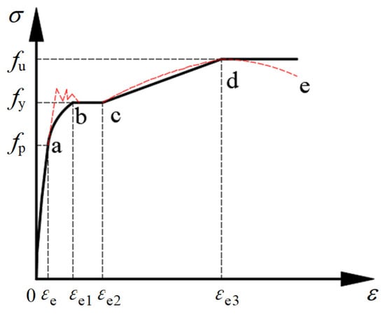
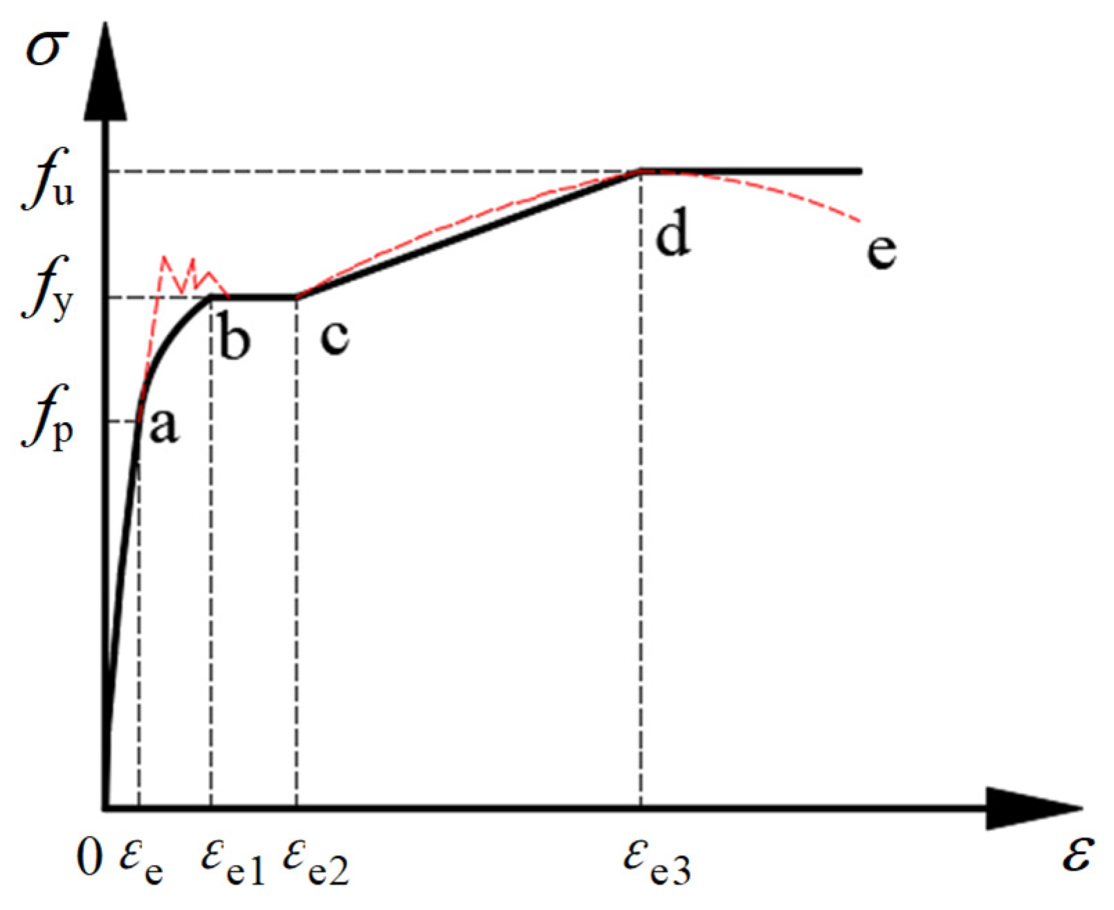
The steel tube was simulated using an elastoplastic constitutive model with isotropic hardening to describe the yielding and post-yield behavior under compression. The stress–strain response was idealized by a bilinear relationship consisting of an initial linear elastic stage followed by strain hardening after yielding. The elastic modulus and Poisson’s ratio of steel were taken as E = 200 GPa and ν = 0.30, respectively. The constitutive model curve was shown in Figure 1.
Figure 1.
Stress–strain curve of engineering low-carbon steel. Points a–e indicate characteristic stages of the tensile response: (a) elastic stage, (b) upper yield point, (c) lower yield point, (d) strain hardening stage, and (e) ultimate stage. The dotted vertical lines denote corresponding characteristic strain values (εₑ, εe1, εe2, εe3). The red dashed line represents the idealized bilinear approximation adopted in the finite element model.
To investigate the influence of steel strength, four yield stress levels were considered, namely fy = 355 MPa, 460 MPa, 550 MPa, and 690 MPa, covering both conventional and high-strength structural steels. After yielding, a strain-hardening modulus equal to 1% of the elastic modulus was assumed. For high-strength structural steels (fy = 550–690 MPa), experimental coupon tests have reported strain-hardening moduli typically ranging from approximately 0.5% to 2% E, depending on steel grade and production process [24,25,26,27]. Therefore, the adoption of 0.01 E represents a mid-range and commonly accepted approximation for numerical simulations when detailed material test data are unavailable.
Moreover, similar bilinear constitutive models with a hardening modulus of 0.01 E have been widely employed in finite element analyses of CFST members and have demonstrated satisfactory agreement with experimental load–displacement responses [28,29]. This modeling strategy has been shown to reasonably capture the post-yield stiffness of steel tubes while maintaining numerical stability in large-deformation analyses.
The steel material was formulated under the finite-strain framework, and geometric nonlinearity was enabled in all analyses to account for large deformation effects and local buckling behavior that may develop during axial compression.
2.2.2. Core Concrete
The concrete infill in CFST specimens was modeled using the Concrete Damaged Plasticity (CDP) model implemented in ABAQUS. The CDP model describes concrete behavior through a combination of isotropic damaged elasticity and plasticity, allowing for stiffness degradation associated with compressive crushing and tensile cracking. This formulation has been extensively adopted for confined concrete in steel tubes and has demonstrated good agreement with experimental observations [30,31].
In the present study, the concrete compressive strength was uniformly taken as fc = 40 MPa, representing a typical strength class used in CFST columns. The uniaxial compressive stress–strain relationship of concrete was defined by a nonlinear curve with an initial elastic response, followed by gradual hardening up to the peak stress and subsequent softening. The elastic modulus of concrete was determined according to empirical relationships recommended in design codes, and a Poisson’s ratio of 0.20 was adopted.
Key CDP parameters were selected based on commonly accepted values reported in the literature to ensure realistic confinement effects and stable numerical convergence. In particular, the dilation angle was set to 30°, reflecting a moderate plastic flow characteristic suitable for concrete confined by steel tubes [32,33]. The flow eccentricity, the ratio of biaxial to uniaxial compressive strength, and the viscosity parameter were assigned following standard recommendations to control the evolution of plastic strain and damage localization.
The constitutive parameters for concrete adopted in the numerical models are summarized in Table 2. To ensure comparability among different specimens, the same material models and parameter values were consistently applied, except for the intentionally varied steel yield strength and the presence or absence of concrete infill. This treatment allows the effects of geometric slenderness (D/t), steel strength, and concrete confinement to be isolated and systematically evaluated.
Table 2.
CDP model parameters.
2.3. Interaction and Boundary Conditions
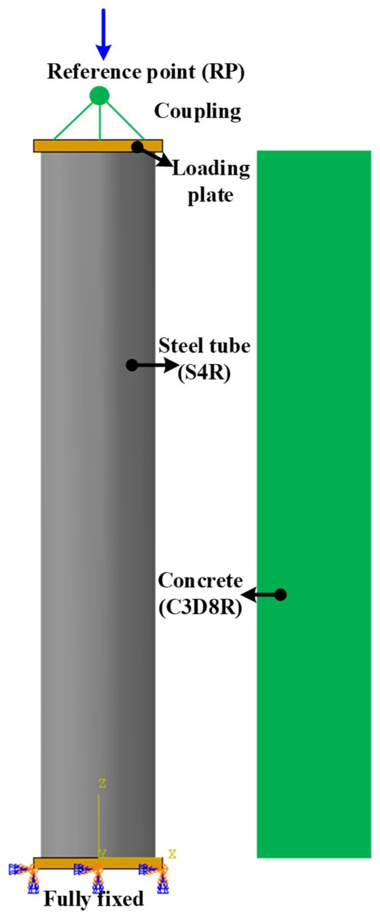
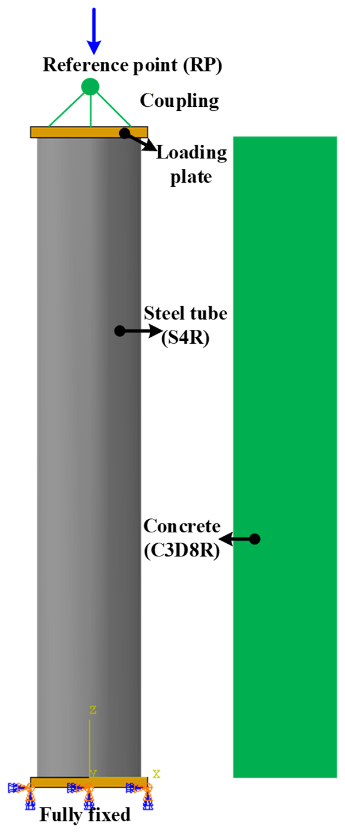
To realistically reproduce the axial compression behavior of CHST and CFST columns, the interaction at the steel–concrete interface, boundary conditions, and geometric imperfections were explicitly considered in the finite element models, as shown in Figure 2. The adopted modeling strategy was aimed at capturing the coupled mechanisms of steel yielding, confinement-induced stress transfer, and instability-driven strength degradation, while maintaining stable numerical performance throughout the nonlinear analyses.
Figure 2.
Finite element model and boundary conditions.
2.3.1. Steel-Concrete Interface Modeling
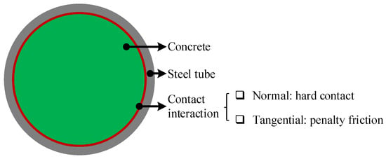
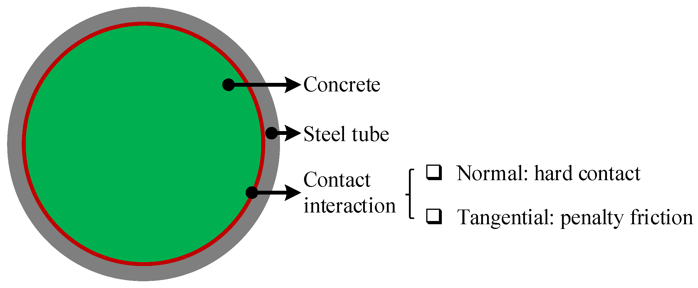
For CFST specimens, the mechanical interaction between the inner surface of the steel tube and the outer surface of the concrete core was represented using a surface-to-surface contact formulation, as shown in Figure 3. In the normal direction, a hard contact relationship was assigned to prevent interpenetration and to allow compressive stress transfer between the steel tube and the infill concrete. In the tangential direction, a penalty-based friction model was employed to describe the potential interface slip and the associated shear transfer mechanism. The friction coefficient was taken as 0.6, which lies within the commonly adopted range (approximately 0.2–0.7) reported for steel–concrete interfaces in CFST numerical simulations, and has been widely used to achieve realistic interaction without enforcing a full bond. This contact-based approach is more physically representative than a fully bonded assumption, as it allows the confinement effect to develop naturally through contact pressure and frictional resistance under axial loading [34,35]. It is noted that the confinement mechanism is dominated by the normal contact pressure (radial restraint), while the friction coefficient mainly affects the extent of tangential slip and local post-peak response; therefore, the primary comparative trends discussed in this study are not expected to be reversed within a reasonable friction range.
Figure 3.
Contact interaction at the steel–concrete interface. The green region represents the concrete core, the gray ring denotes the steel tube, and the red line indicates the contact interface. Arrows illustrate the contact interaction definition between the steel tube and concrete core.
For CHST specimens, the concrete core was omitted and the steel tube was analyzed as a hollow member with identical geometric dimensions.
2.3.2. Boundary Conditions and Loading Method
To ensure a uniform introduction of axial load and to reduce spurious end effects, rigid end plates were attached to both ends of the specimens. The bottom end plate was fully restrained, providing a stable reference boundary condition. At the top end, a reference point (RP) was introduced and coupled to the loading end plate through a kinematic coupling constraint, such that the axial displacement applied at the RP was distributed evenly over the cross-section.
All specimens were subjected to displacement-controlled monotonic compression. The axial shortening was applied along the longitudinal axis of the column, while lateral translations and rotational degrees of freedom at the loading RP were constrained to avoid unintended eccentricity. Geometric nonlinearity was activated in all analyses to account for large displacement and rotation effects, which are essential for capturing post-yield deformation and buckling-related response.
2.3.3. Initial Geometric Imperfections
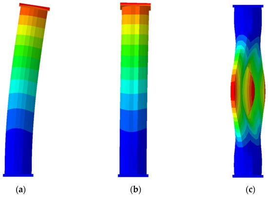
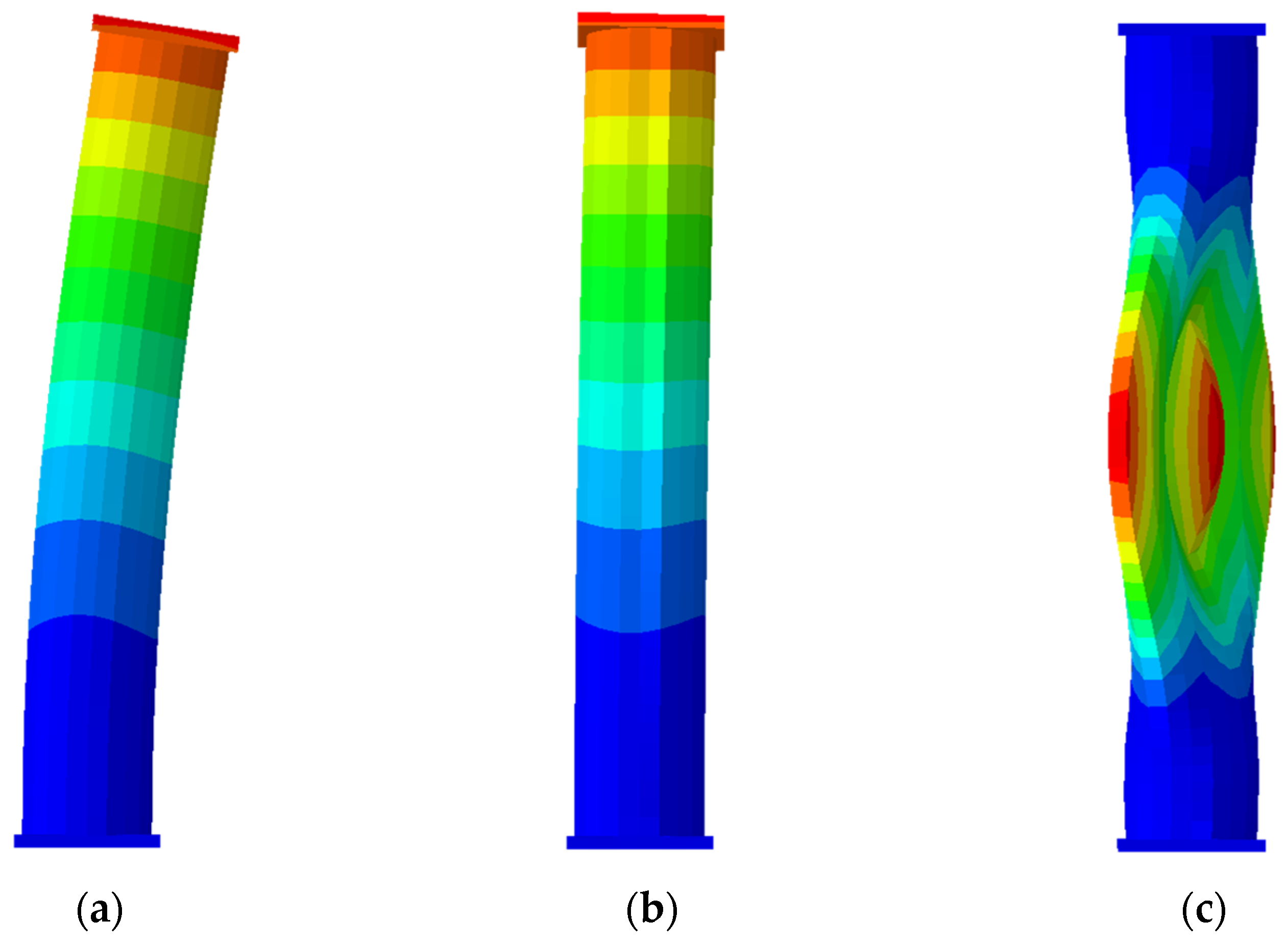
Considering the sensitivity of thin-walled steel tubes to buckling, initial geometric imperfections were introduced to trigger realistic instability patterns. A linear eigenvalue buckling analysis was first conducted to obtain representative mode shapes, as shown in Figure 4, and the resulting eigenmodes were then embedded into the nonlinear model as an initial imperfection field. In this study, the dominant (first) buckling mode was adopted as the imperfection shape, because it provides the lowest-energy global instability pattern and has been widely used in GMNIA of tubular members to ensure stable triggering of post-peak degradation [28,36,37].
Figure 4.
First three eigenvalue buckling mode shapes used to define initial geometric imperfections for specimen S3: (a) 1st global flexural mode; (b) 2nd global flexural mode; (c) 3rd local shell buckling mode (local bulging). The color contours represent the normalized displacement magnitude of each eigenmode, where red indicates the maximum deformation and blue indicates the minimum deformation.
To further quantify the influence of imperfection amplitude, a sensitivity analysis was performed for specimen S3 by varying the amplitude to L/1500, L/1000, and L/500 while keeping the same imperfection shape (1st mode). The predicted peak axial capacity showed only minor variation (Nu = 780, 768, and 753 kN, respectively), with a maximum deviation within approximately ±2% relative to the baseline case (L/1000). The ultimate deformation capacity exhibited a modest change (δu = 4.3–5.2 mm), indicating that larger imperfections slightly accelerate the development of geometric nonlinearity and lead to a smoother post-peak response, while the overall failure mode remains unchanged. The imperfection amplitude was set to L/1000, where L is the specimen length. This magnitude has been widely adopted for tubular members and has been shown to provide a reasonable representation of fabrication-related geometric deviations without artificially exaggerating instability effects [36,37].
Introducing this imperfection enables the simulation to develop progressive local buckling and post-peak degradation in a consistent and physically meaningful manner, particularly for specimens with relatively large diameter-thickness ratios.
2.3.4. Nonlinear Solution and Output Quantities
A nonlinear static analysis procedure was conducted to trace the full axial load–displacement response up to failure. The equilibrium path was obtained using an incremental-iterative solution scheme with automatic step size control, which allows the model to pass through nonlinear stiffness transitions associated with yielding, confinement, and local buckling.
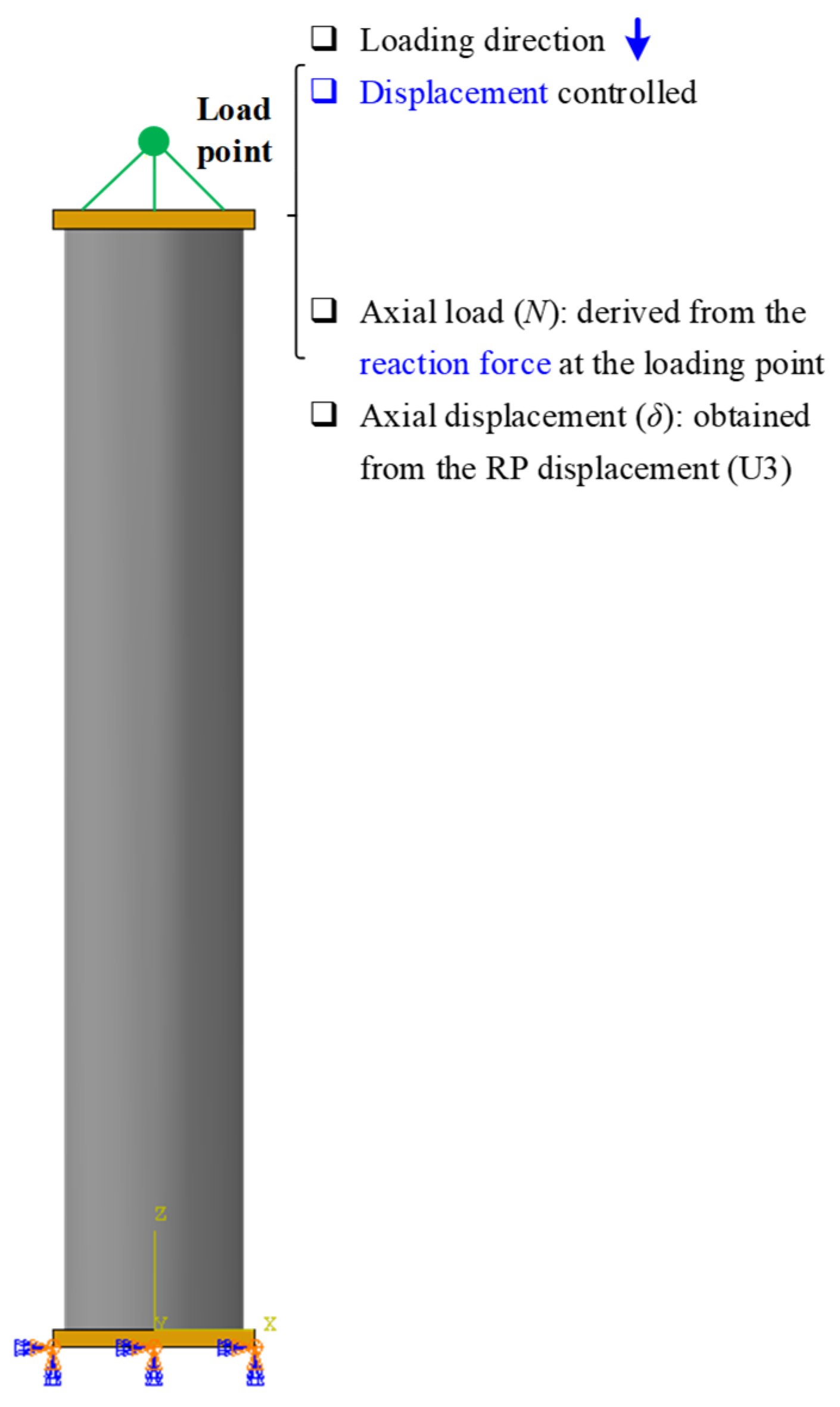
The axial load was extracted from the reaction force at the loading reference point, and the corresponding axial displacement was obtained from the imposed shortening. In addition to the global load–displacement relationship, local response quantities were recorded to support mechanism interpretation, including the von Mises stress in the steel tube, as well as the damage evolution and compressive plastic strain in the concrete core. These outputs provide a basis for identifying the governing failure mode and evaluating the influence of D/t ratio, steel yield strength, and concrete infill.
2.4. Finite Element Discretization and Mesh Sensitivity
The finite element discretization was designed to accurately capture the nonlinear response of both steel tubes and core concrete, including local buckling of thin-walled steel and the confinement-induced stress redistribution in CFST members. A mesh strategy balancing computational efficiency and numerical accuracy was adopted for all specimens.
2.4.1. Element Types and Mesh Strategy
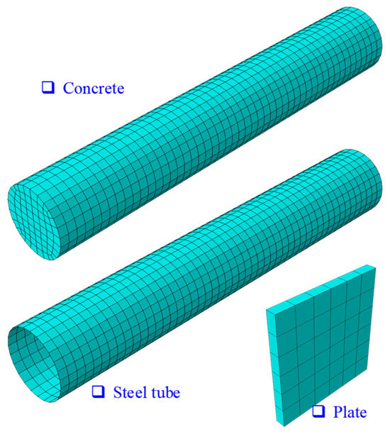
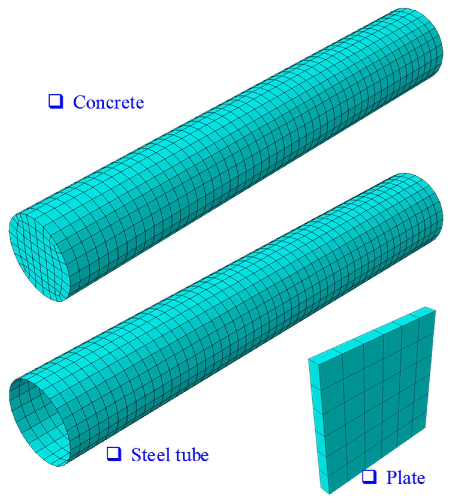
The steel tube was modeled using four-node doubly curved reduced-integration shell elements (S4R), which are well suited for thin-walled tubular members and can efficiently capture large deformation and local buckling behavior, as shown in Figure 5. The concrete core, when present, was discretized using eight-node linear brick elements with reduced integration (C3D8R), which provide a robust representation of three-dimensional stress states and nonlinear damage evolution in concrete under compression.
Figure 5.
Mesh discretization of steel tube and concrete core.
To ensure a consistent comparison across the parametric cases, a structured meshing scheme was employed. The circumferential mesh density of the steel tube was kept identical for specimens with the same diameter, while the mesh size along the axial direction was controlled to properly resolve local buckling waves and plastic hinge development. For the concrete core, the mesh was aligned with the steel tube discretization to facilitate stable contact interaction and avoid excessive mesh distortion near the interface.
2.4.2. Mesh Sensitivity Study
A mesh sensitivity study was conducted to confirm that the predicted axial load–displacement response was not significantly affected by mesh refinement. A representative specimen (D = 159 mm, t = 4.5 mm, with and without concrete infill) was selected, and three mesh levels (coarse, medium, and fine) were compared.
The results indicate that the global response, including the initial stiffness and ultimate axial capacity, converges satisfactorily with mesh refinement. The medium mesh was therefore adopted for the full parametric study, providing a reliable prediction of peak load and post-peak degradation while maintaining reasonable computational cost.
2.4.3. Output Resolution
To support mechanism interpretation and facilitate quantitative comparison among specimens, both global and local response quantities were extracted. The global axial force was obtained from the reaction force at the loading reference point, and the axial shortening was measured from the imposed displacement. Local quantities, including steel von Mises stress, equivalent plastic strain, and concrete damage variables, were recorded to identify the governing failure modes and the evolution of confinement effects.
2.5. Model Validation
To ensure the reliability of the finite element model established in this study, a comparison with available experimental results was conducted for a representative CFST column under axial compression. Such validation against measured load–displacement responses is essential to demonstrate that the adopted material models, interaction definitions, and numerical procedures can accurately capture the physical behavior of concrete-filled steel tube (CFST) columns.
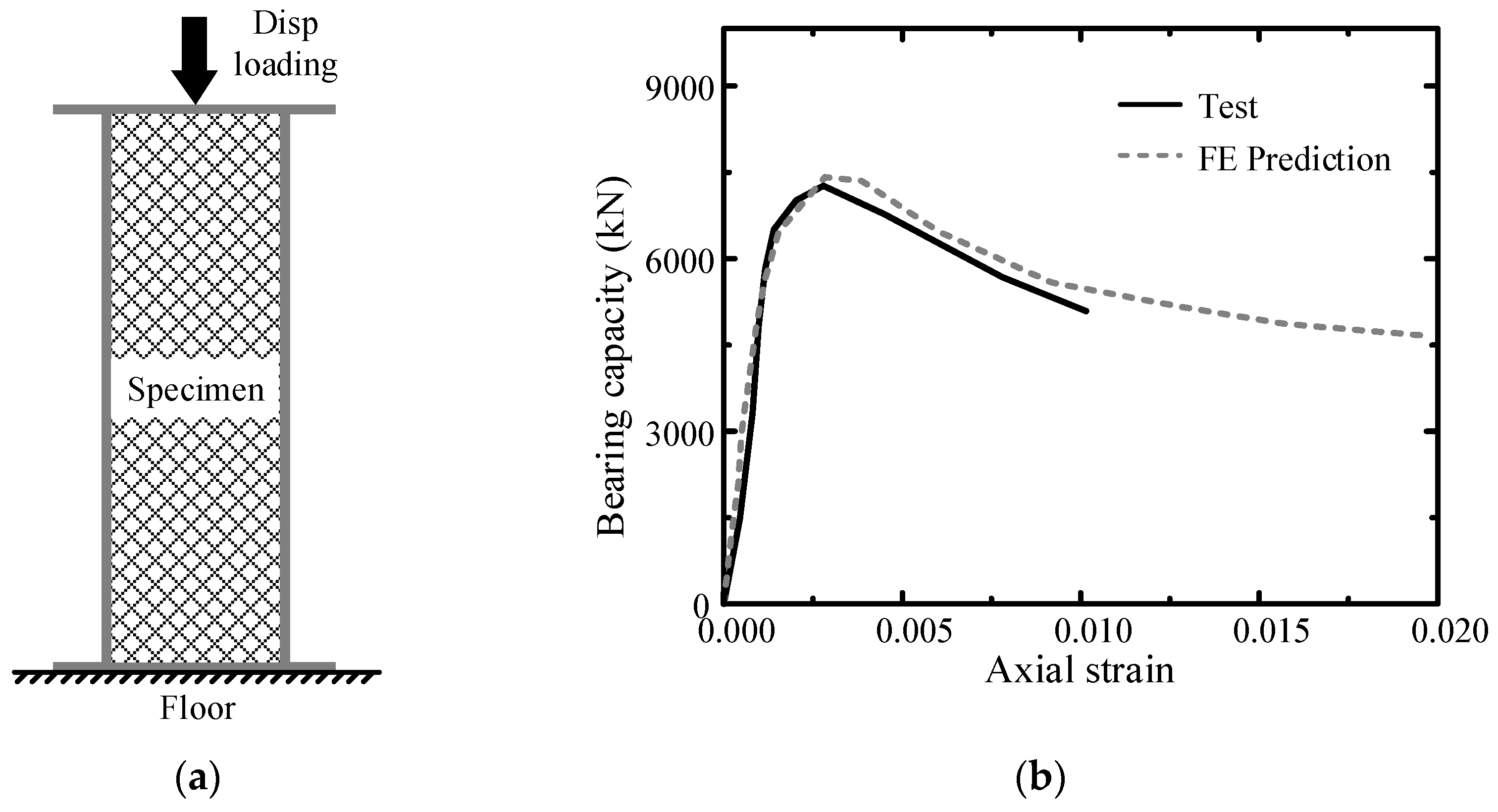
Among the relevant experimental investigations, several studies have systematically examined the axial compressive performance of CFST stub columns with various geometric and material configurations. For instance, Lu et al. carried out axial compression tests on square CFST stub columns with low steel ratio under monotonic loading and provided complete load–displacement curves that can be used for validation purposes [38]. Typical test data from this work, corresponding to a CFST specimen with a core concrete compressive strength of approximately 40 MPa and similar diameter–thickness ratio as the present models, were extracted for comparison.
In the finite element model of the validation case, the specimen geometry, material properties, and boundary conditions were set consistent with the reported test configuration. The CDP concrete model and bilinear steel constitutive model introduced in Section 2.2 and Section 2.3 were applied without additional tuning. The numerical axial load–displacement response was then obtained under displacement-controlled monotonic compression to failure.
Figure 6 presents the comparison between the experimental and numerical axial load–displacement curves. Good agreement is observed in both the initial stiffness and peak load, indicating that the model captures the transition from elastic behavior to yielding and eventual strength degradation. To further quantify the agreement, the percentage error in peak axial load was calculated as Equation (1). The FE model predicts a peak load of 7417 kN, compared with the experimental value of 7268 kN, resulting in a difference of approximately 2.05%. This level of deviation is within the commonly accepted range for nonlinear simulation of confined concrete members, confirming the reliability of the adopted modeling strategy. While minor discrepancies may exist in the post-peak softening branch due to experimental variability and concrete cracking localization, the overall trend and peak capacity are well predicted, demonstrating the ability of the adopted modeling approach to reproduce key features of CFST column behavior. It should be noted that the experimental loading was terminated when the load decreased to approximately 85% of the peak value for safety considerations. The numerical model, however, was allowed to continue without experimental constraints, which explains the longer post-peak tail observed in the FE response.
This validation gives confidence that the finite element framework established herein can serve as a reliable tool for the subsequent parametric studies on the effects of diameter–thickness ratio, steel strength, and concrete infill.
Figure 6.
Validation of ultimate axial capacity for SCFT-1: (a) Loading setup in the experiment (Lu et al.); (b) Comparison between experimental and FE axial load–strain curves.
3. Results and Discussion
3.1. Post-Processing Procedure and Evaluation Metrics
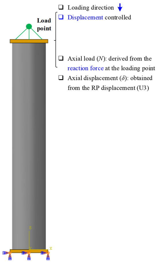
The axial compression response of each specimen was evaluated based on the reaction force and axial shortening extracted from the reference point (RP) at the loading end, as shown in Figure 7. The axial load capacity (N) was obtained by summing the reaction force components along the loading direction, while the axial displacement (δ) was taken as the imposed shortening of the RP. Accordingly, the global axial load–displacement relationship (N–δ) was established for all CHST and CFST specimens.
Figure 7.
Definition of axial load and displacement extraction.
To facilitate a consistent comparison among different parameter combinations, several key performance indicators were defined. The ultimate axial capacity Nu was determined as the peak value of the N–δ curve. The initial axial stiffness K0 was evaluated from the slope of the load–displacement curve within the initial linear range, where the response remained predominantly elastic. In addition, the deformation capacity was quantified by tracking the displacement corresponding to a prescribed strength degradation level after the peak load, allowing the post-peak stability to be compared among specimens with different diameter–thickness ratios and steel strengths.
In addition to the global response, local mechanical behavior was interpreted through the distributions of von Mises stress in the steel tube, as well as the damage evolution in the concrete core for CFST specimens. These quantities were used to identify the governing failure modes and to clarify the role of concrete confinement in delaying local buckling and stabilizing the post-peak response.
3.2. Axial Load–Displacement Curves
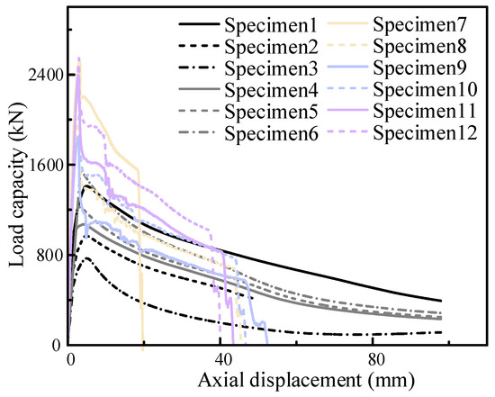
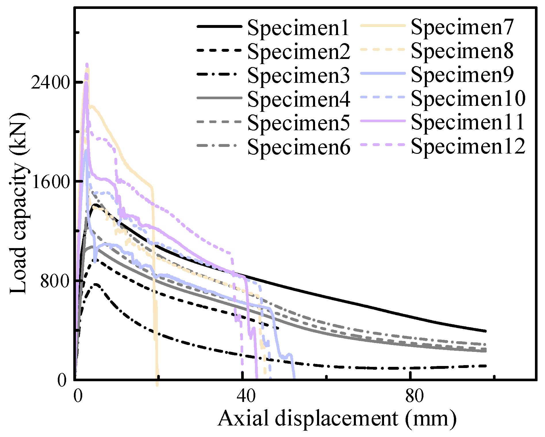
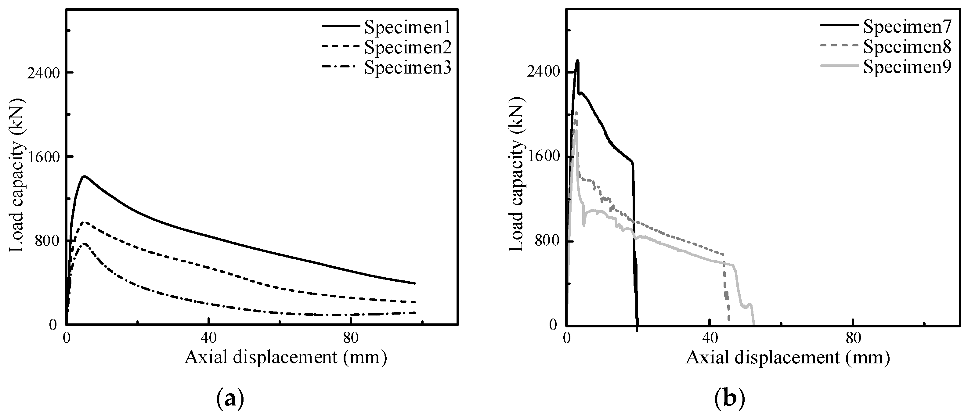
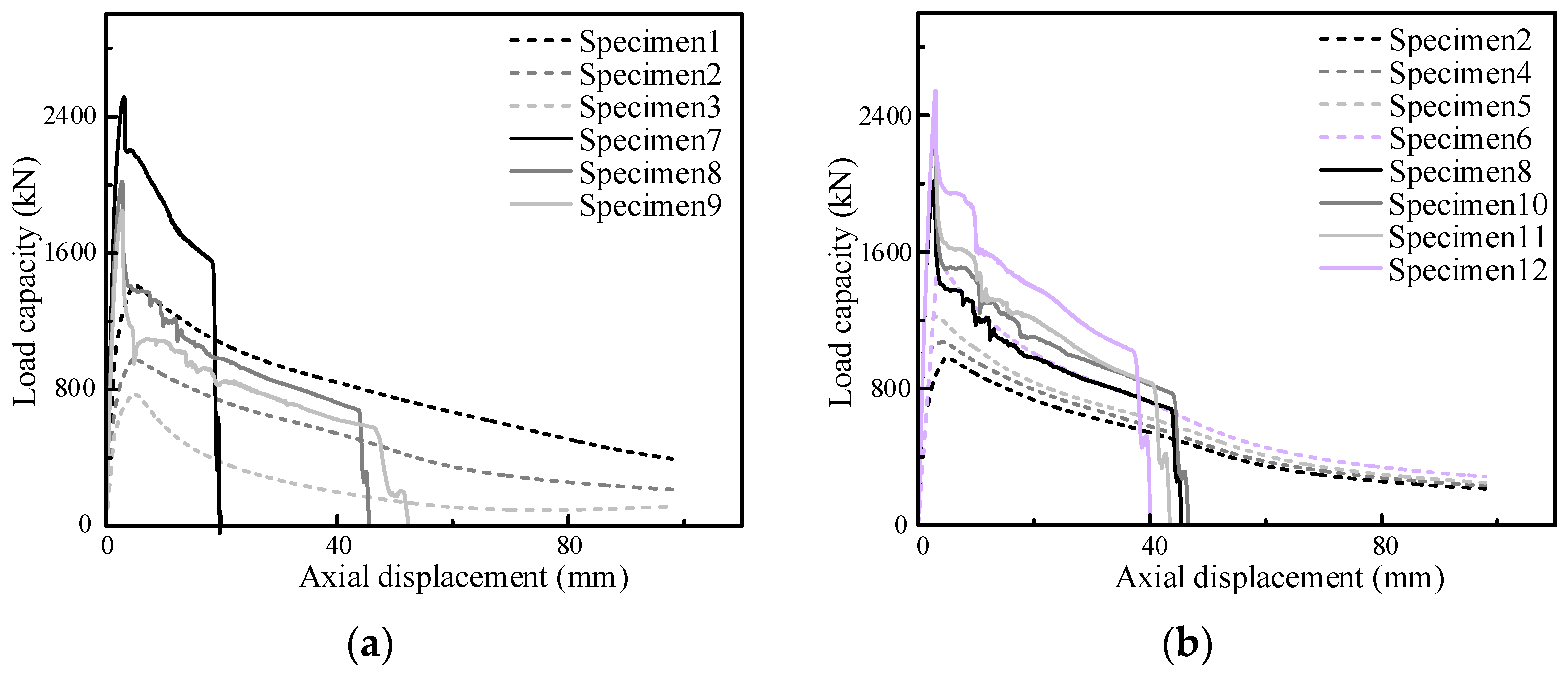
Figure 8 compares the axial load–displacement responses of all specimens under monotonic compression. The curves show a typical nonlinear evolution consisting of an initial elastic stage, a rapid transition to yielding-dominated response, and a post-peak degradation phase governed by local buckling and progressive material damage. Although the overall trend is similar among specimens, the peak load, post-peak stability, and residual capacity are clearly affected by the diameter–thickness ratio, steel yield strength, and the presence of concrete infill.
Figure 8.
Comparison of axial bearing capacity of specimens.
3.2.1. Influence of Diameter–Thickness Ratio (D/t)
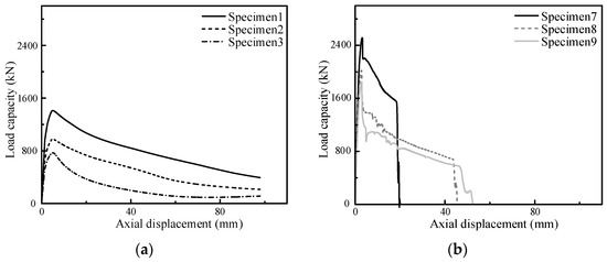
The effect of tube wall slenderness is illustrated in Figure 9, where specimens with different D/t ratios are compared for both CHST and CFST configurations. For hollow tubes (Figure 9a), decreasing D/t (i.e., increasing wall thickness) leads to a higher peak axial capacity and a more stable post-peak response. In contrast, thin-walled specimens with larger D/t exhibit earlier strength degradation and a steeper descending branch, which can be attributed to the premature development of local buckling in the steel tube wall.
Figure 9.
Effect of D/t on axial load–displacement response: (a) CHST; (b) CFST (C40).
When concrete infill is introduced (Figure 9b), the overall response becomes noticeably more stable. Compared with the corresponding CHST specimens, CFST columns exhibit increased peak capacity and delayed post-peak deterioration. This improvement is mainly associated with the confinement provided by the concrete core, which suppresses inward local buckling and promotes a more uniform stress distribution along the steel tube. Notably, the beneficial contribution of concrete infill becomes more pronounced for larger D/t ratios, indicating that concrete confinement plays a critical role in stabilizing thin-walled steel tubes under axial compression.
3.2.2. Influence of Steel Grade
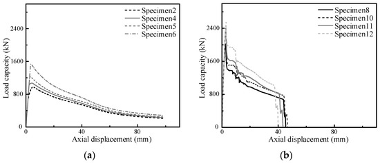
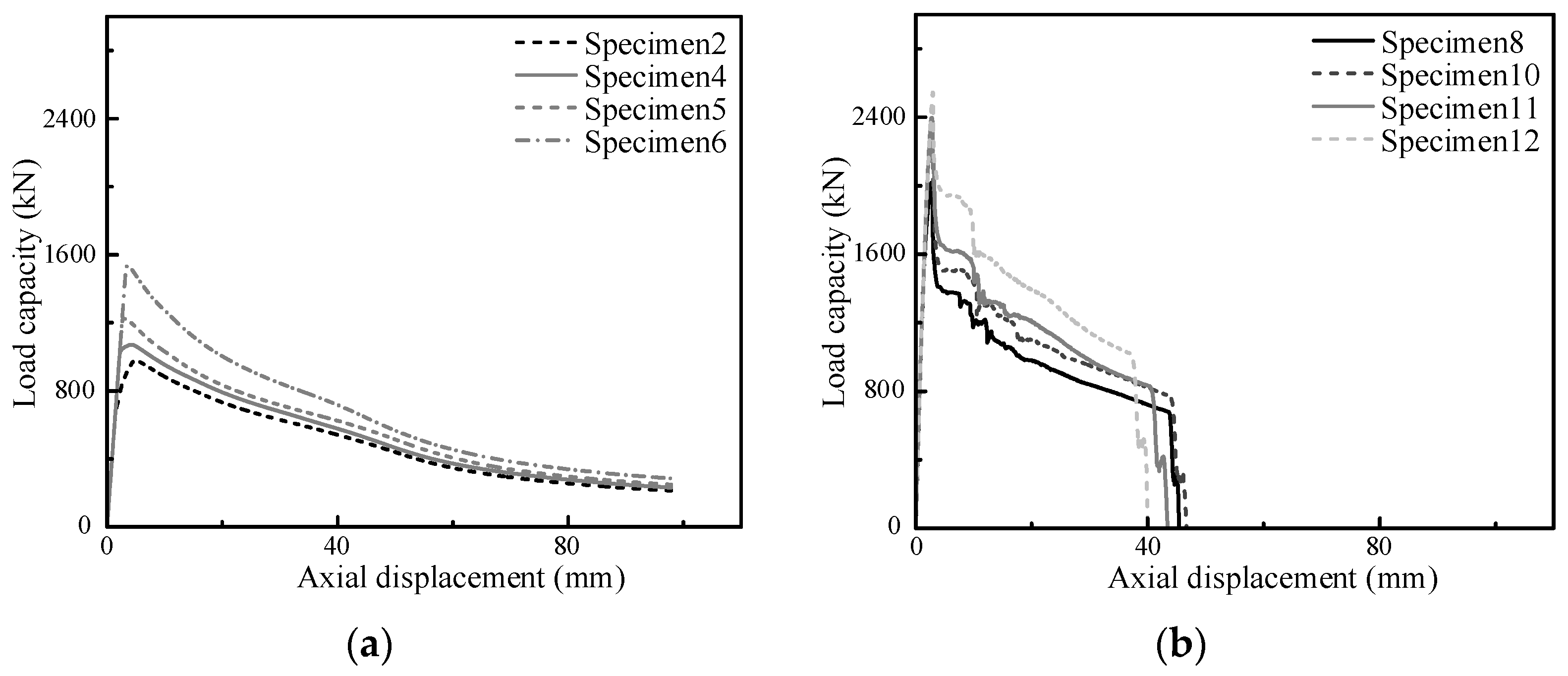
Figure 10 presents the responses of specimens with different steel yield strengths while keeping the geometry unchanged. For CHST specimens (Figure 10a), increasing fy results in a clear enhancement of peak axial capacity. However, the post-peak degradation trends remain comparable, suggesting that the deformation stability is primarily controlled by wall slenderness rather than yield strength alone.
Figure 10.
Effect of steel yield strength on axial response: (a) CHST; (b) CFST (C40).
For CFST specimens (Figure 10b), a similar increase in peak load is observed with higher steel strength. In addition, the descending branches show a relatively smoother reduction in load compared with CHST, reflecting the stabilizing effect of the concrete core. Nevertheless, although higher steel yield strength enhances the peak axial capacity, its influence on post-peak deformation capacity is relatively limited. The overall descending trends remain comparable, suggesting that deformation stability is mainly governed by wall slenderness and confinement effects rather than steel strength alone.
3.2.3. Role of Concrete Infill
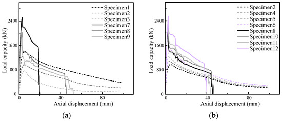
To further highlight the composite action, Figure 11 directly compares CHST and CFST specimens under different steel strength levels. The results demonstrate that concrete infill substantially increases the axial load-bearing capacity and improves the post-peak response. For the normal-strength steel cases (Figure 11a), the enhancement is evident in both peak load and residual strength. For higher-strength steel tubes (Figure 11b), the concrete infill remains effective in stabilizing the response, although the relative gain in peak capacity becomes less pronounced due to the already increased contribution from the steel tube.
Figure 11.
Comparison between CHST and CFST responses: (a) fy = 355 MPa; (b) fy = 355–690 MPa.
Overall, the axial load–displacement curves confirm that the axial compressive behavior of tubular columns is governed by the coupled effects of wall slenderness, steel yielding capacity, and concrete confinement. In the following section, the stress redistribution and damage evolution are examined to clarify the underlying mechanisms responsible for the observed global responses.
3.3. Stress Distribution and Damage Evolution
3.3.1. Steel Tube Stress Evolution (Specimens 1–6)
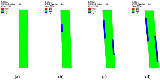
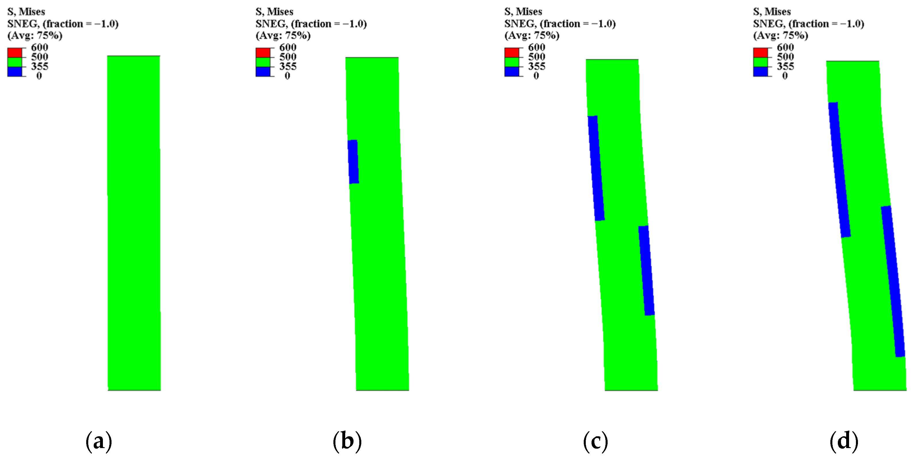
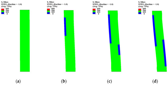
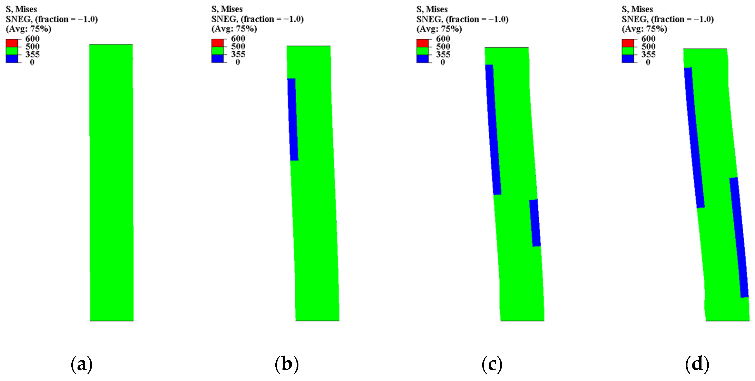
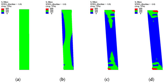
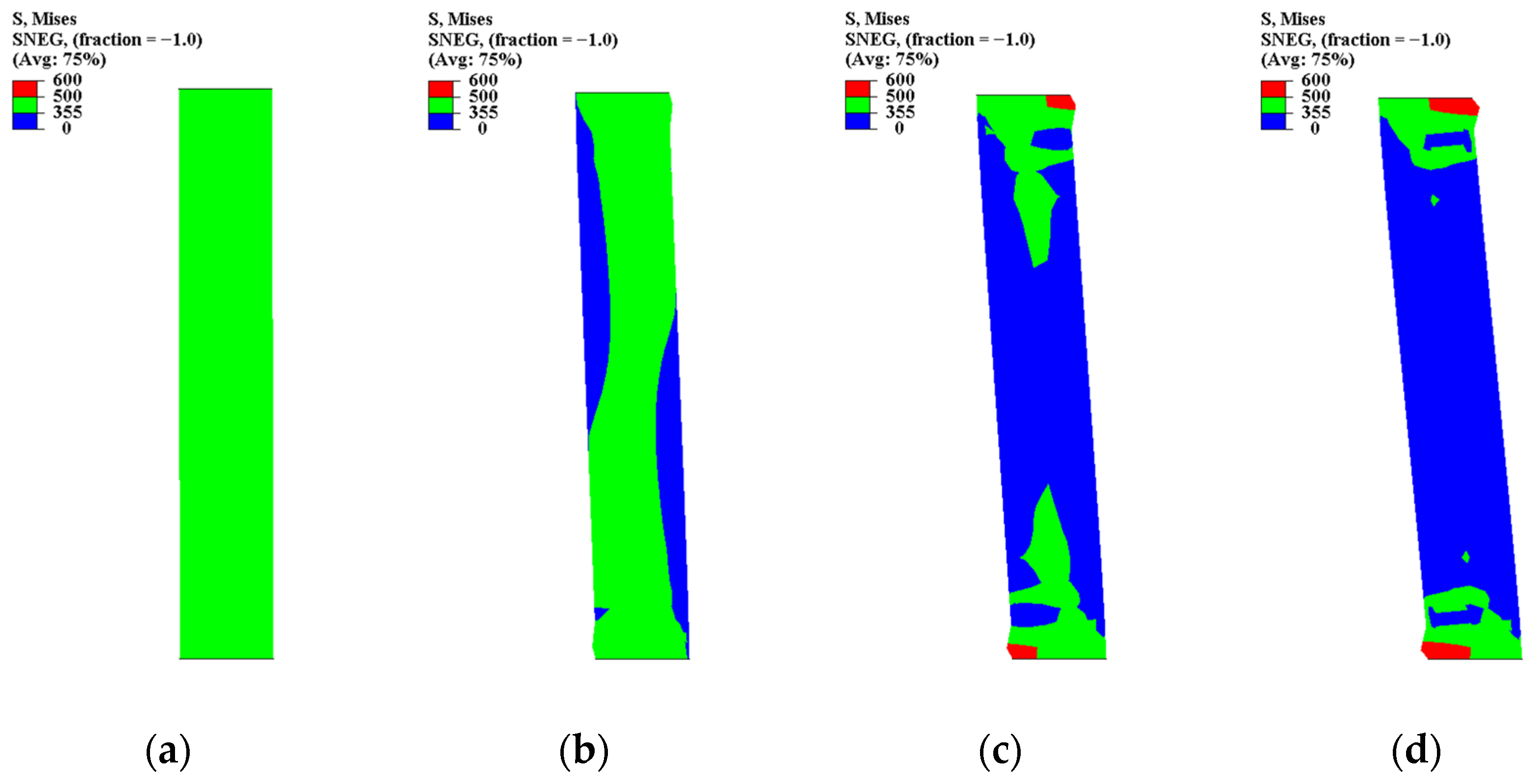
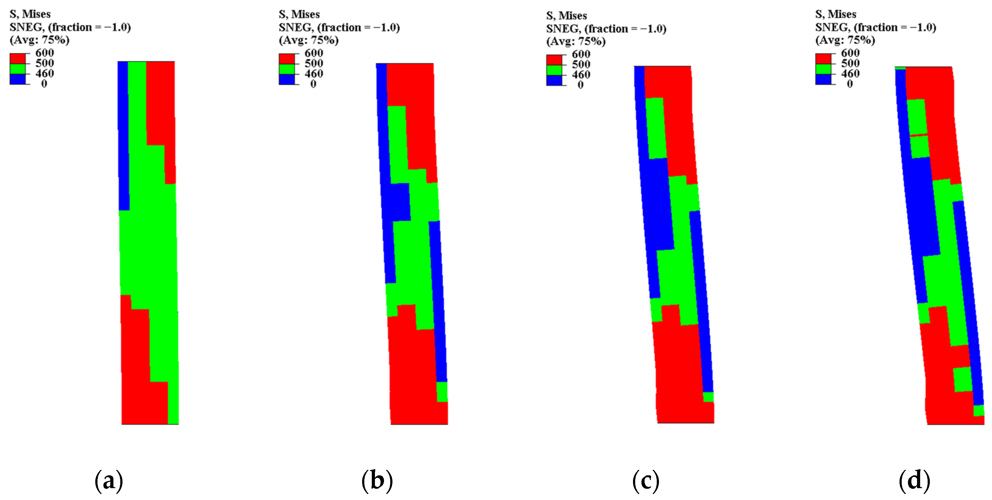
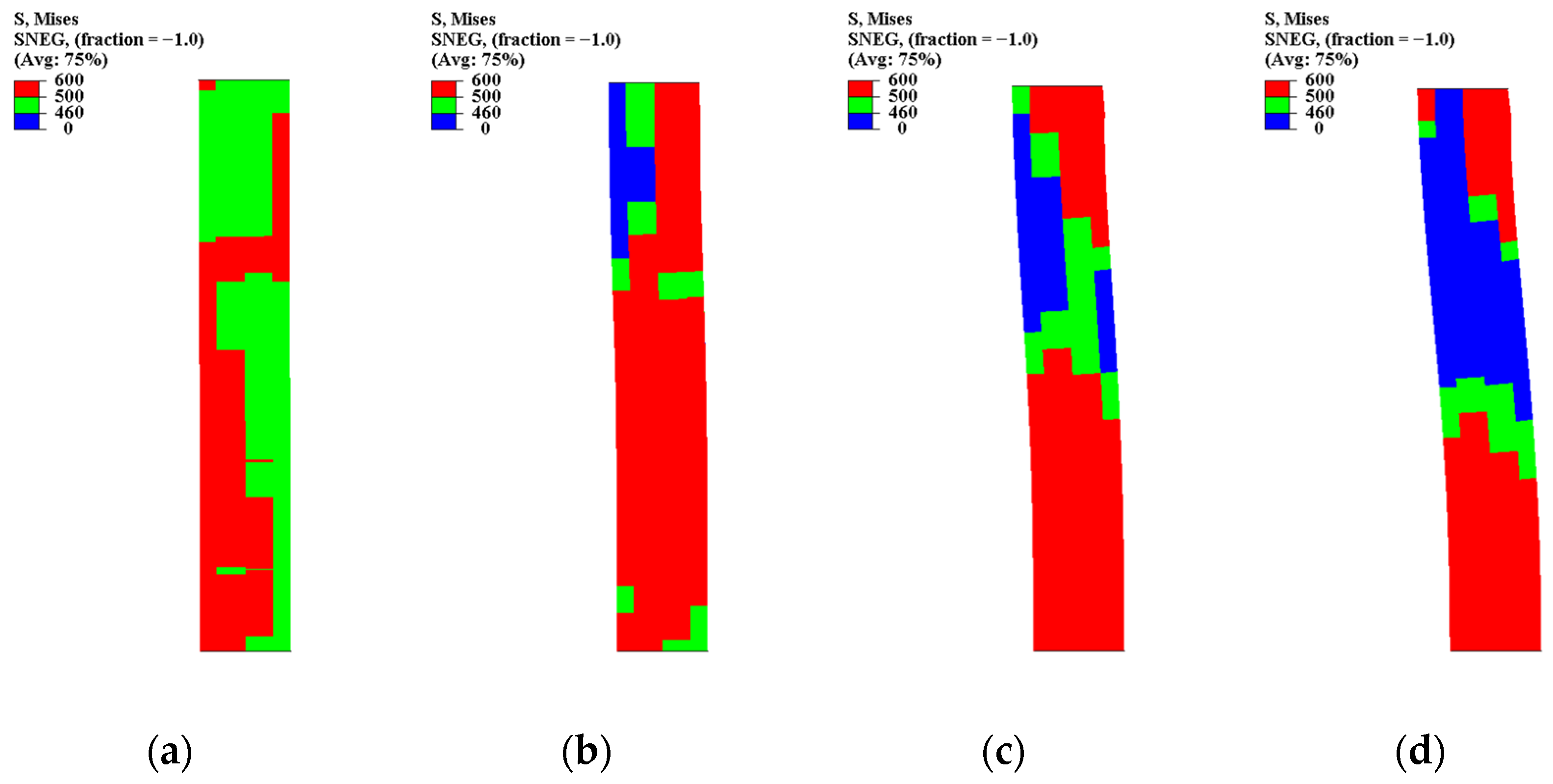
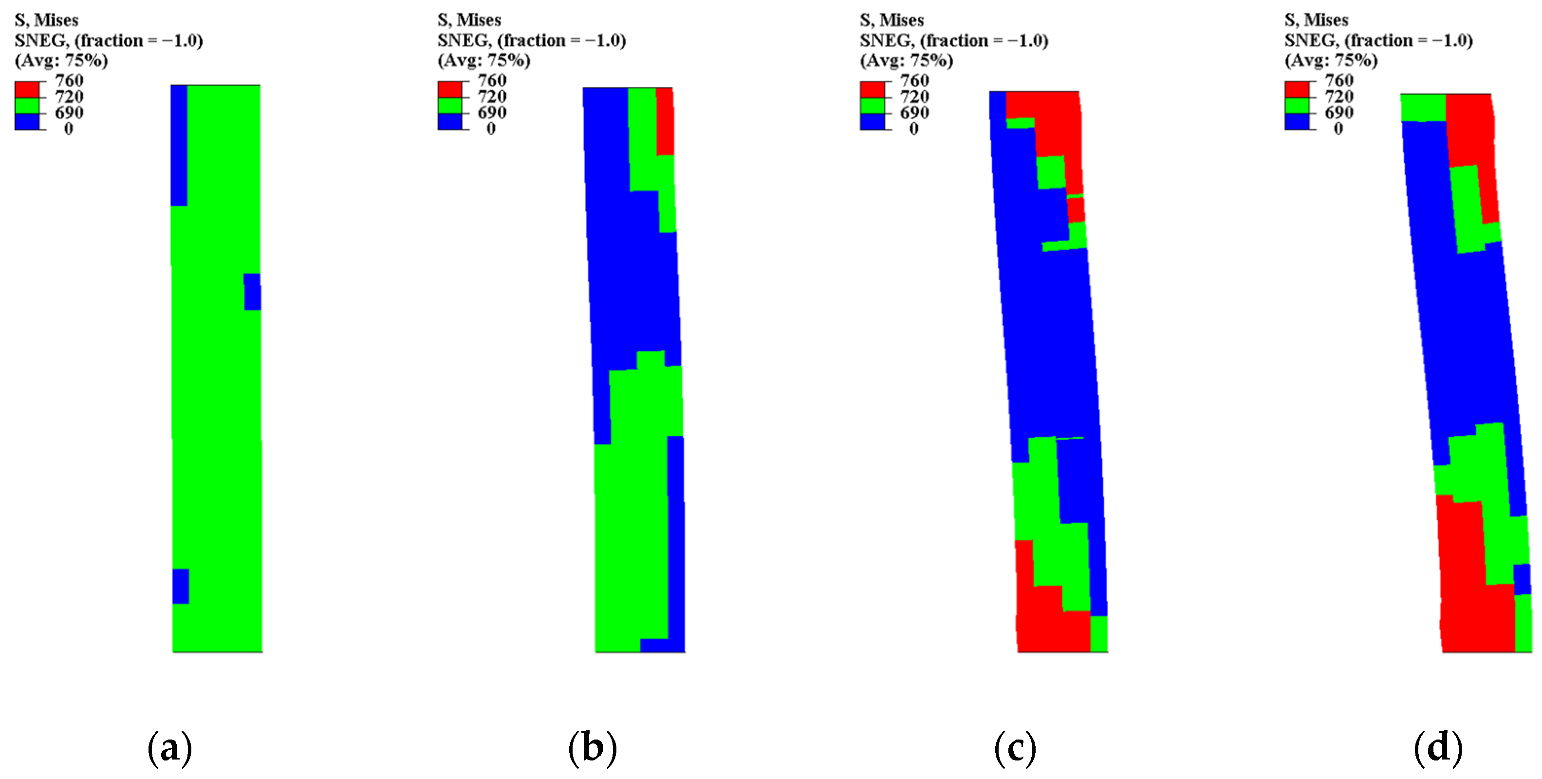
Figure 12, Figure 13, Figure 14, Figure 15, Figure 16 and Figure 17 present the von Mises stress contours of the hollow steel tube specimens at increasing axial displacements. For Specimen 1 (Figure 12), the stress field remained nearly uniform at 5 mm displacement, indicating elastic-dominated behavior. At 10 mm, localized stress concentrations emerged near the mid-height, marking the onset of plastic yielding. With further loading (15–20 mm), an inclined plastic band developed and propagated toward the column ends, accompanied by clear geometric distortion. The final stage was characterized by end-region localization, suggesting local buckling-driven collapse.
Figure 12.
Steel tube Von Mises cloud diagram of Specimen 1: (a) Axial displacement: 5 mm; (b) Axial displacement: 10 mm; (c) Axial displacement: 15 mm; (d) Axial displacement: 20 mm.
Figure 13.
Steel tube Von Mises cloud diagram of Specimen 2: (a) Axial displacement: 5 mm; (b) Axial displacement: 10 mm; (c) Axial displacement: 15 mm; (d) Axial displacement: 20 mm.
Figure 14.
Steel tube Von Mises cloud diagram of Specimen 3: (a) Axial displacement: 5 mm; (b) Axial displacement: 10 mm; (c) Axial displacement: 15 mm; (d) Axial displacement: 20 mm.
Figure 15.
Steel tube Von Mises cloud diagram of Specimen 4: (a) Axial displacement: 5 mm; (b) Axial displacement: 10 mm; (c) Axial displacement: 15 mm; (d) Axial displacement: 20 mm.
Figure 16.
Steel tube Von Mises cloud diagram of Specimen 5: (a) Axial displacement: 5 mm; (b) Axial displacement: 10 mm; (c) Axial displacement: 15 mm; (d) Axial displacement: 20 mm.
Figure 17.
Steel tube Von Mises cloud diagram of Specimen 6: (a) Axial displacement: 5 mm; (b) Axial displacement: 10 mm; (c) Axial displacement: 15 mm; (d) Axial displacement: 20 mm.
A similar evolution pattern was observed in Specimen 2 (Figure 13), although the plastic zones formed earlier and expanded more rapidly. The stress localization became more pronounced at 15 mm, and a continuous plastic strip dominated the compression side at 20 mm. This indicates reduced shell stability compared with Specimen 1.
For Specimen 3 (Figure 14), the stress redistribution was significantly more severe. At 10 mm displacement, large plastic regions already occupied a substantial portion of the tube wall. By 15 mm, the stress field became highly asymmetric, and strong localization occurred at both ends. The rapid expansion of plastic zones reflects a higher susceptibility to local buckling.
Specimens 4–6 (Figure 15, Figure 16 and Figure 17) exhibited increasingly concentrated plastic regions as the diameter–thickness ratio increased and steel strength varied. The stress contours reveal that higher strength steel delayed the initial yielding but resulted in sharper localization once plasticity developed. The post-yield behavior was governed by narrow plastic zones and pronounced end instability, explaining the steep post-peak degradation observed in the global response.
Overall, the hollow specimens demonstrated a consistent failure mechanism dominated by local shell buckling. The plastic zones initiated as localized patches and evolved into inclined bands, eventually collapsing into end-concentrated plastic hinges.
3.3.2. Concrete-Filled Specimens (Specimens 7–9)
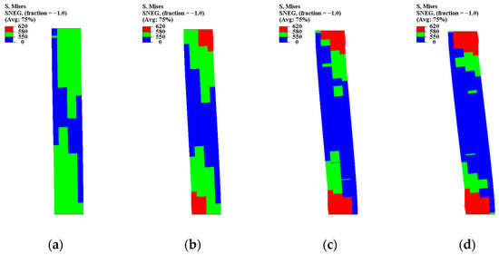
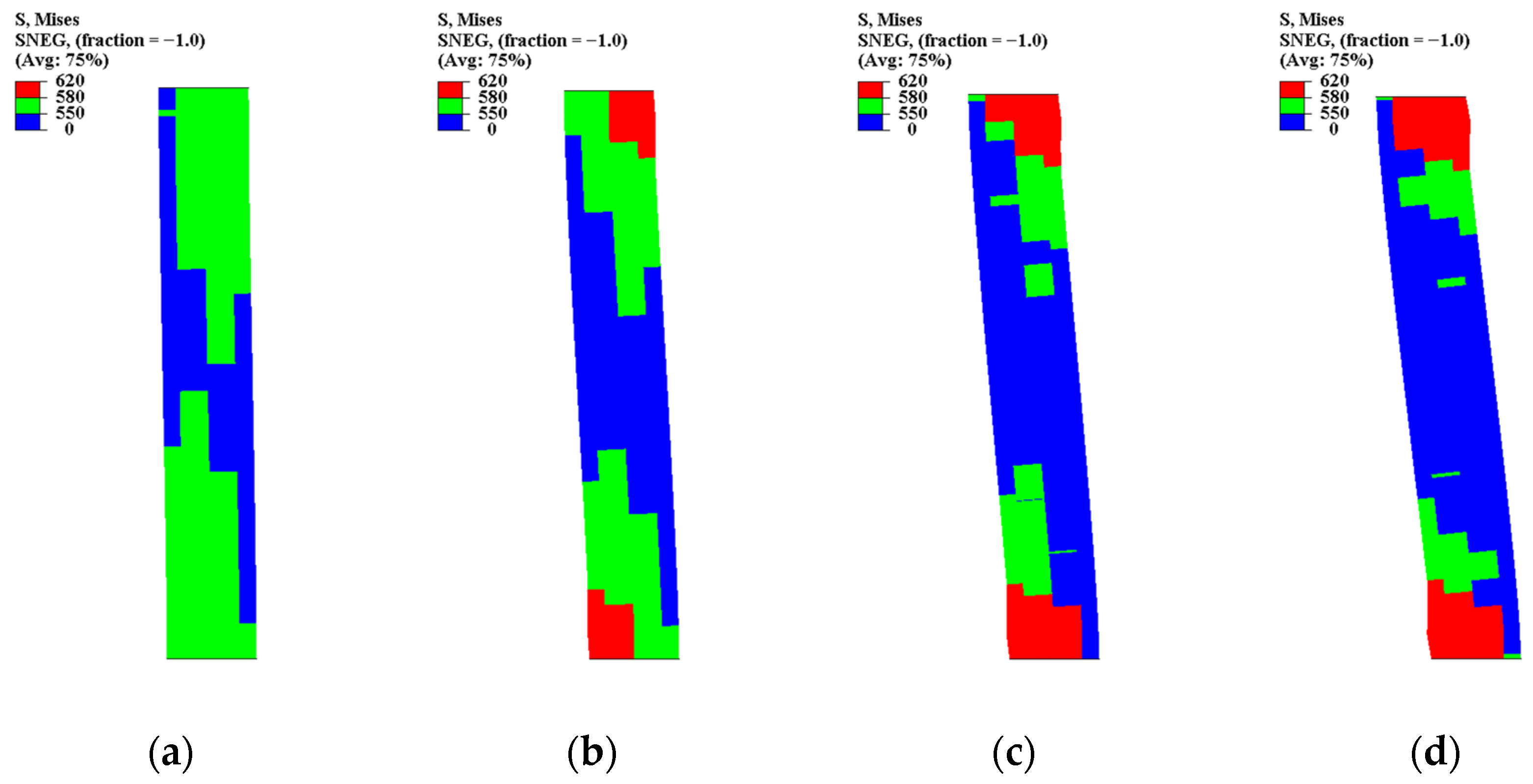
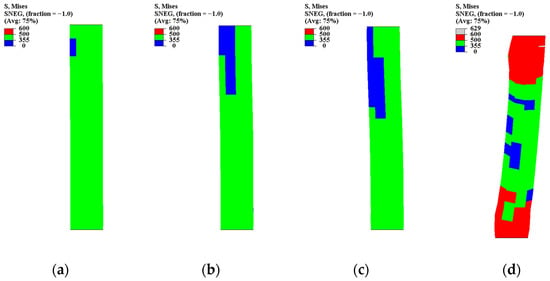
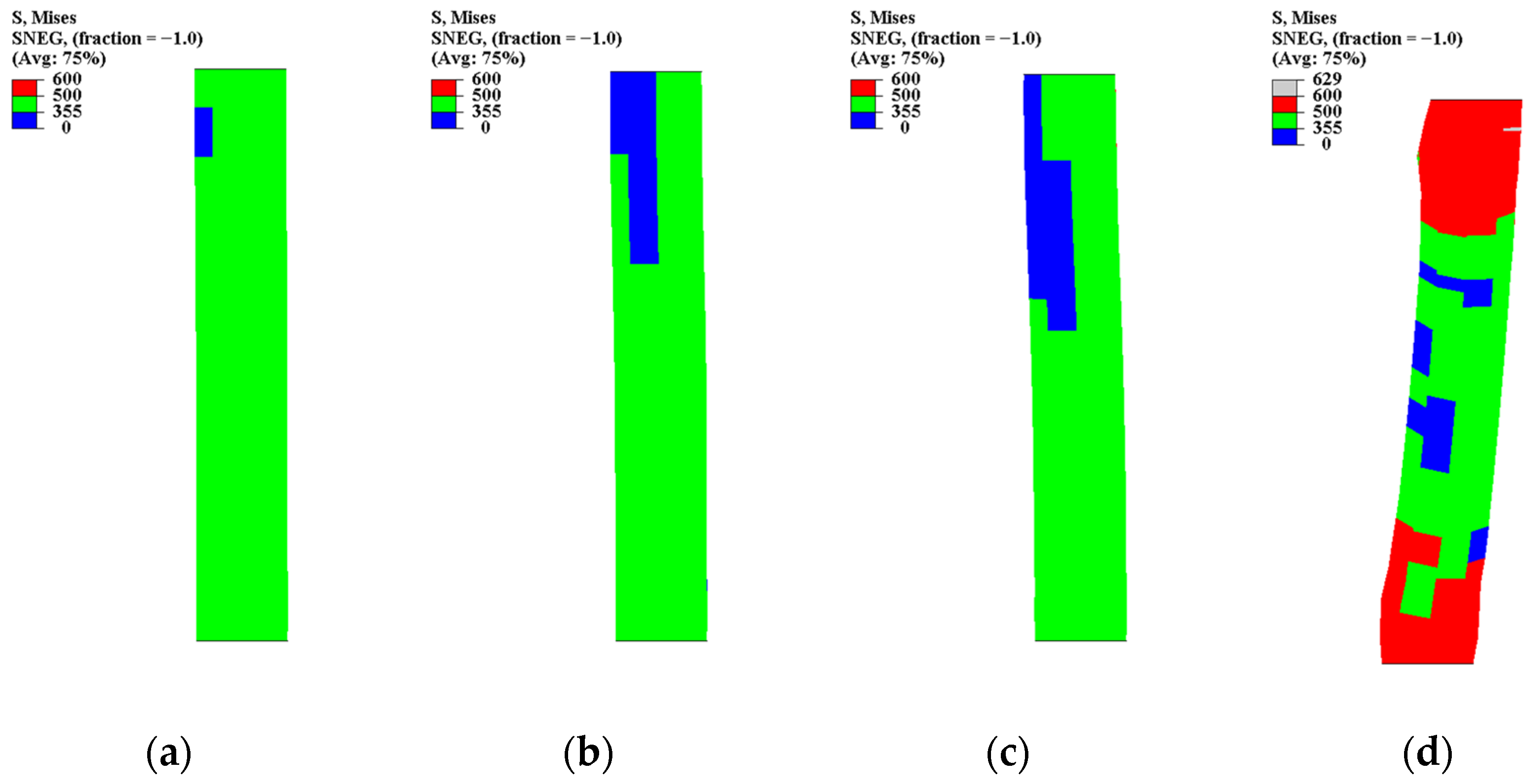
The stress contours of the concrete-filled specimens (Figure 18, Figure 19 and Figure 20) differ markedly from those of the hollow tubes. For Specimen 7 (Figure 18), the stress field remained relatively uniform even at 10 mm displacement, and plastic regions developed gradually. The inclined bands were shorter and less pronounced, indicating that the concrete core effectively restrained inward buckling of the steel tube.
Figure 18.
Steel tube Von Mises cloud diagram of Specimen 7: (a) Axial displacement: 5 mm; (b) Axial displacement: 10 mm; (c) Axial displacement: 15 mm; (d) Axial displacement: 20 mm.
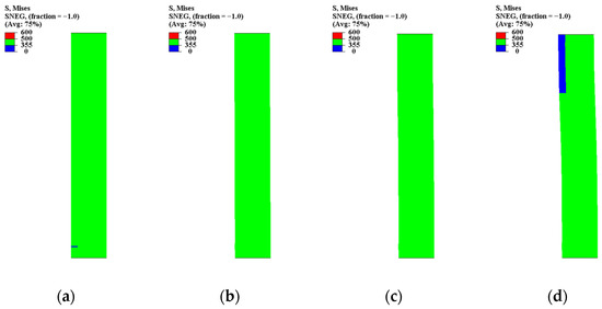
Figure 19.
Steel tube Von Mises cloud diagram of Specimen 8: (a) Axial displacement: 5 mm; (b) Axial displacement: 10 mm; (c) Axial displacement: 15 mm; (d) Axial displacement: 20 mm.
Figure 20.
Steel tube Von Mises cloud diagram of Specimen 9: (a) Axial displacement: 5 mm; (b) Axial displacement: 10 mm; (c) Axial displacement: 15 mm; (d) Axial displacement: 20 mm.
Specimen 8 (Figure 19) exhibited even more stable stress redistribution. Plastic zones appeared as scattered patches rather than continuous bands, suggesting improved load-sharing between steel and concrete. The stress concentration near the ends was significantly reduced compared with the hollow counterparts.
For Specimen 9 (Figure 20), localized yielding was still present but spread over a larger region. The confinement effect allowed the plastic zones to expand without immediate localization. As a result, the deformation remained more stable at 20 mm displacement, demonstrating enhanced ductility and post-peak resistance.
These observations confirm that the concrete infill provides lateral support to the steel tube, delays local buckling, and promotes distributed plasticity.
3.3.3. High-Strength Steel Specimens (Specimens 10–12)
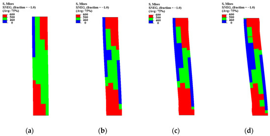
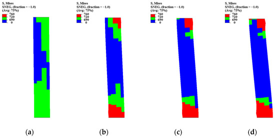
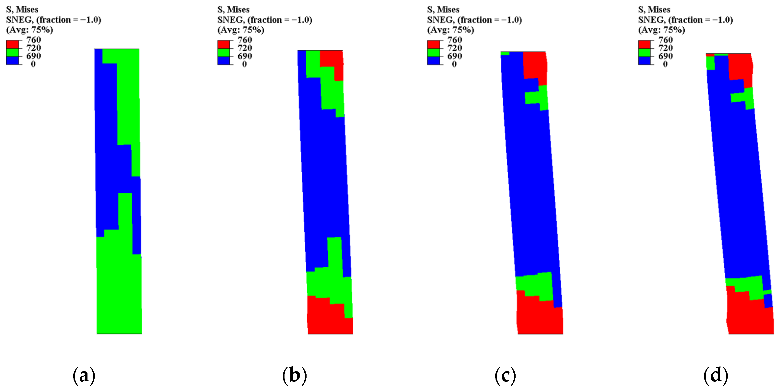
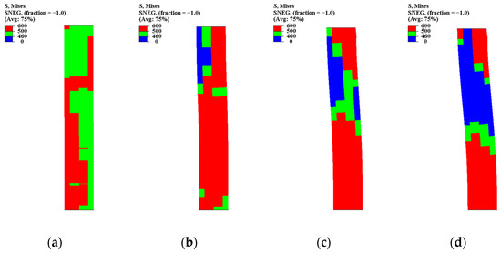
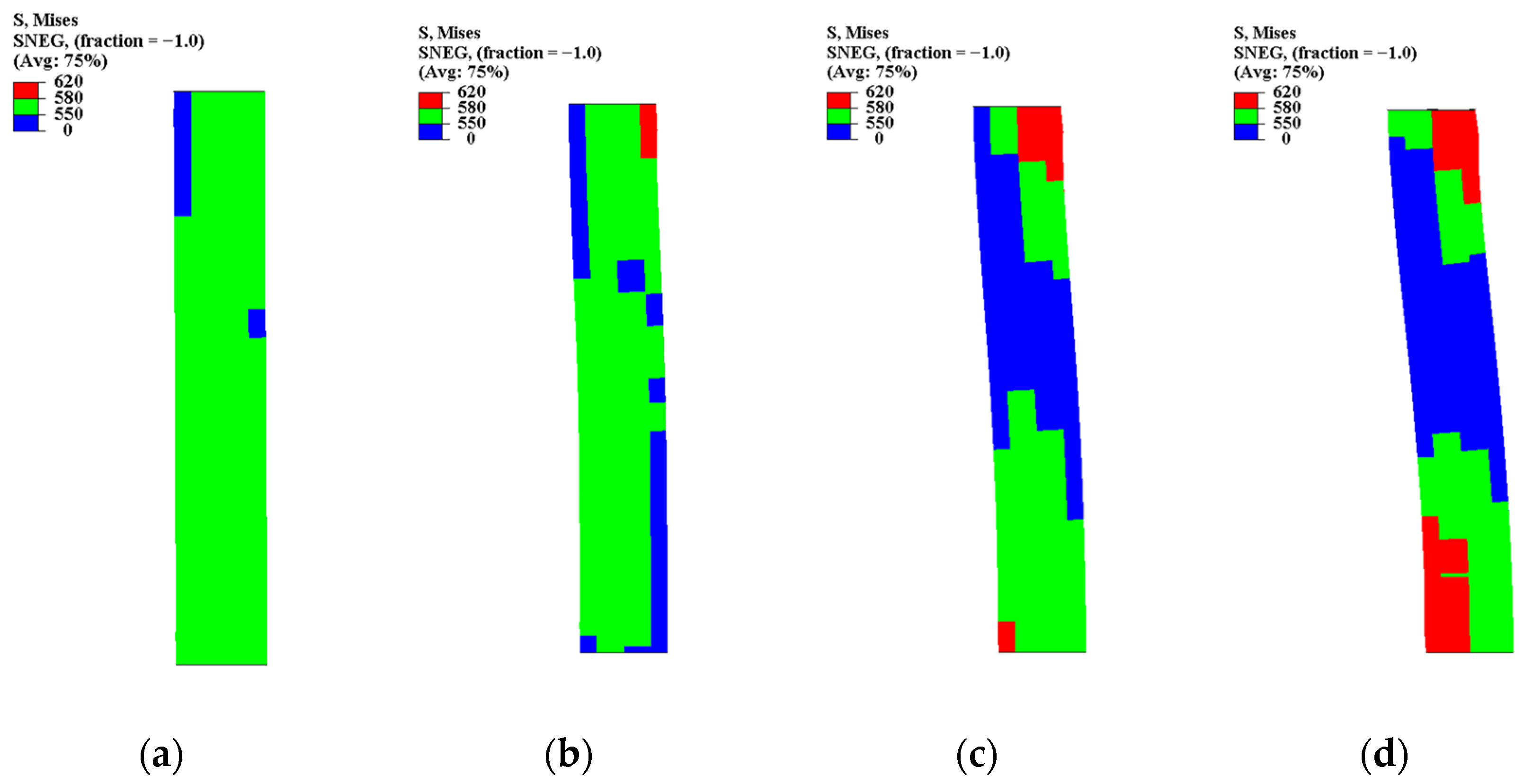
Figure 21, Figure 22 and Figure 23 show the stress evolution of the high-strength steel specimens. In Specimen 10 (Figure 21), plastic zones formed abruptly once yielding was reached. The stress field transitioned rapidly from elastic to localized plasticity, and large red regions appeared at relatively small displacements.
Figure 21.
Steel tube Von Mises cloud diagram of Specimen 10: (a) Axial displacement: 5 mm; (b) Axial displacement: 10 mm; (c) Axial displacement: 15 mm; (d) Axial displacement: 20 mm.
Figure 22.
Steel tube Von Mises cloud diagram of Specimen 11: (a) Axial displacement: 5 mm; (b) Axial displacement: 10 mm; (c) Axial displacement: 15 mm; (d) Axial displacement: 20 mm.
Figure 23.
Steel tube Von Mises cloud diagram of Specimen 12: (a) Axial displacement: 5 mm; (b) Axial displacement: 10 mm; (c) Axial displacement: 15 mm; (d) Axial displacement: 20 mm.
Specimen 11 (Figure 22) displayed similar behavior but with slightly more distributed plastic regions. Nevertheless, the plastic zones remained narrower than those in lower-strength specimens, indicating limited plastic spreading.
Specimen 12 (Figure 23) exhibited the most concentrated stress pattern. Once yielding initiated, the plastic zones propagated quickly toward the ends, forming a distinct plastic hinge. The rapid localization explains the reduced deformation capacity observed in the load–displacement response.
These results indicate that increasing steel yield strength enhances peak load capacity. However, the relative contribution of strain hardening becomes less pronounced, and once local buckling initiates, stress redistribution occurs over a narrower region. Consequently, post-peak degradation is governed primarily by instability development rather than intrinsic material brittleness.
3.3.4. Concrete Compressive and Tensile Damage Evolution
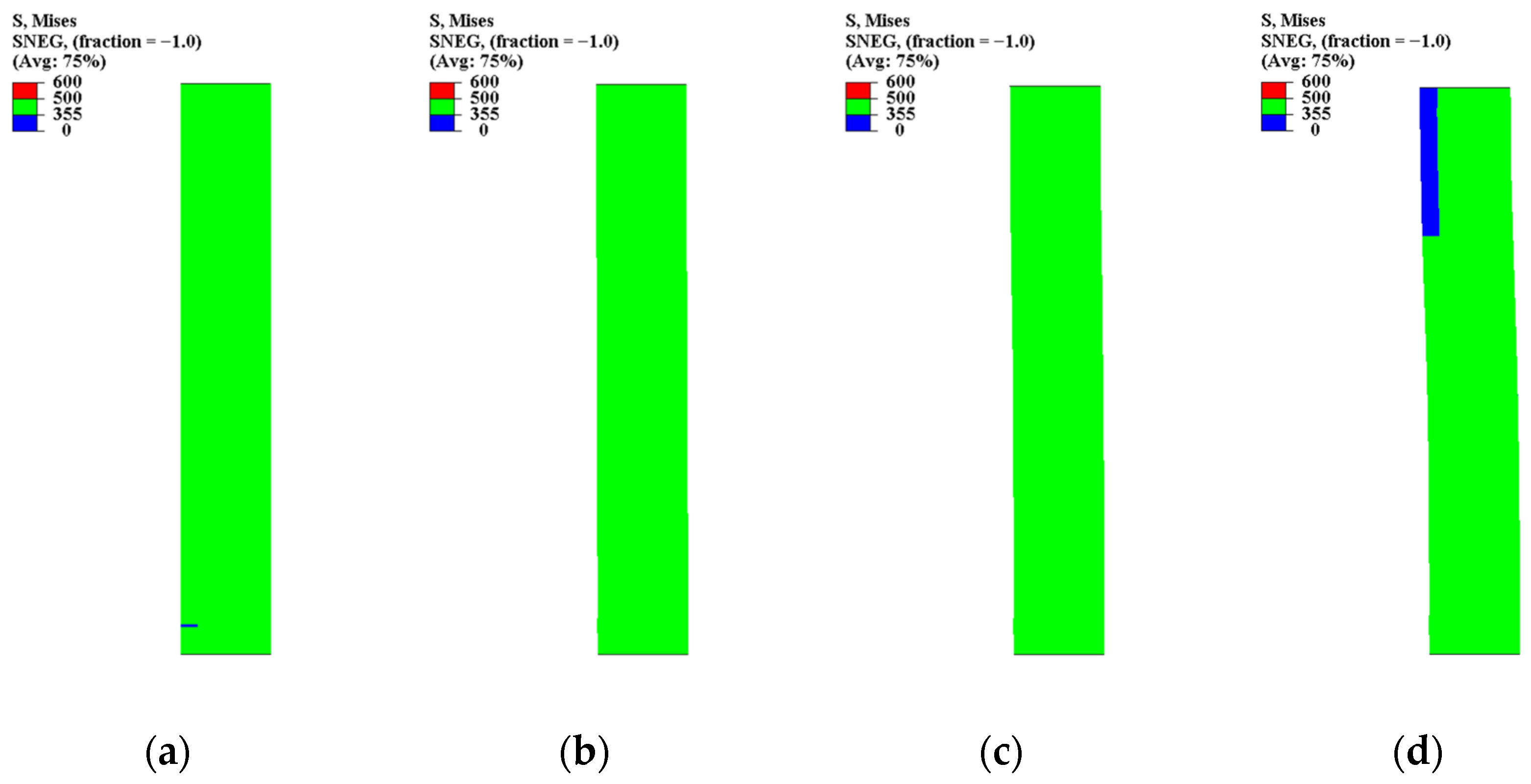
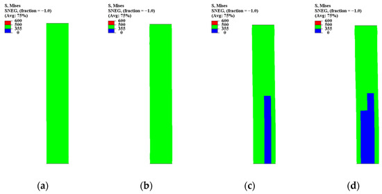
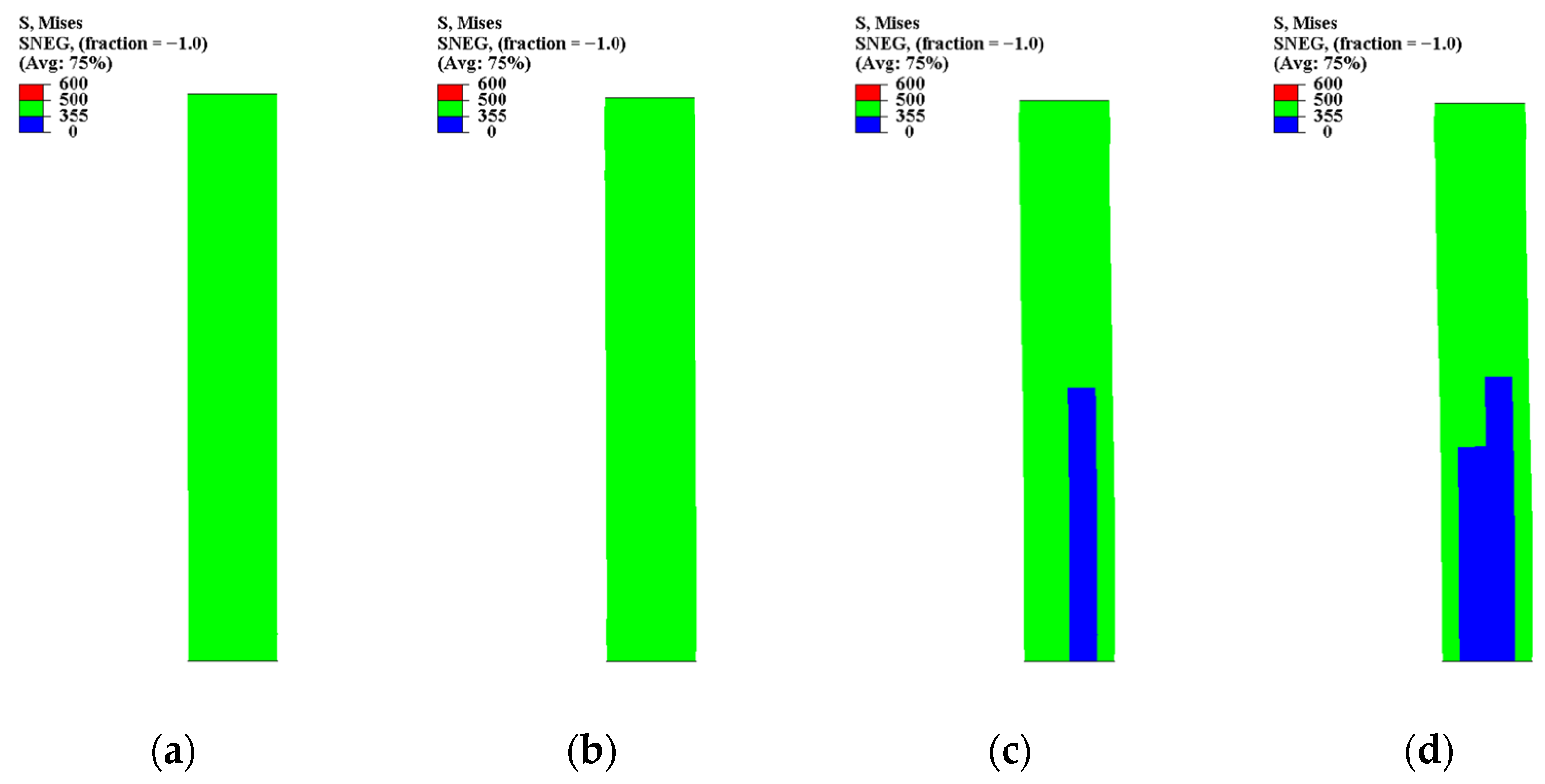
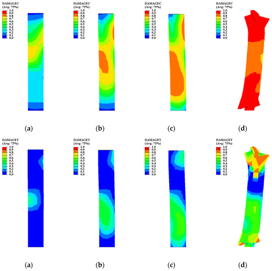
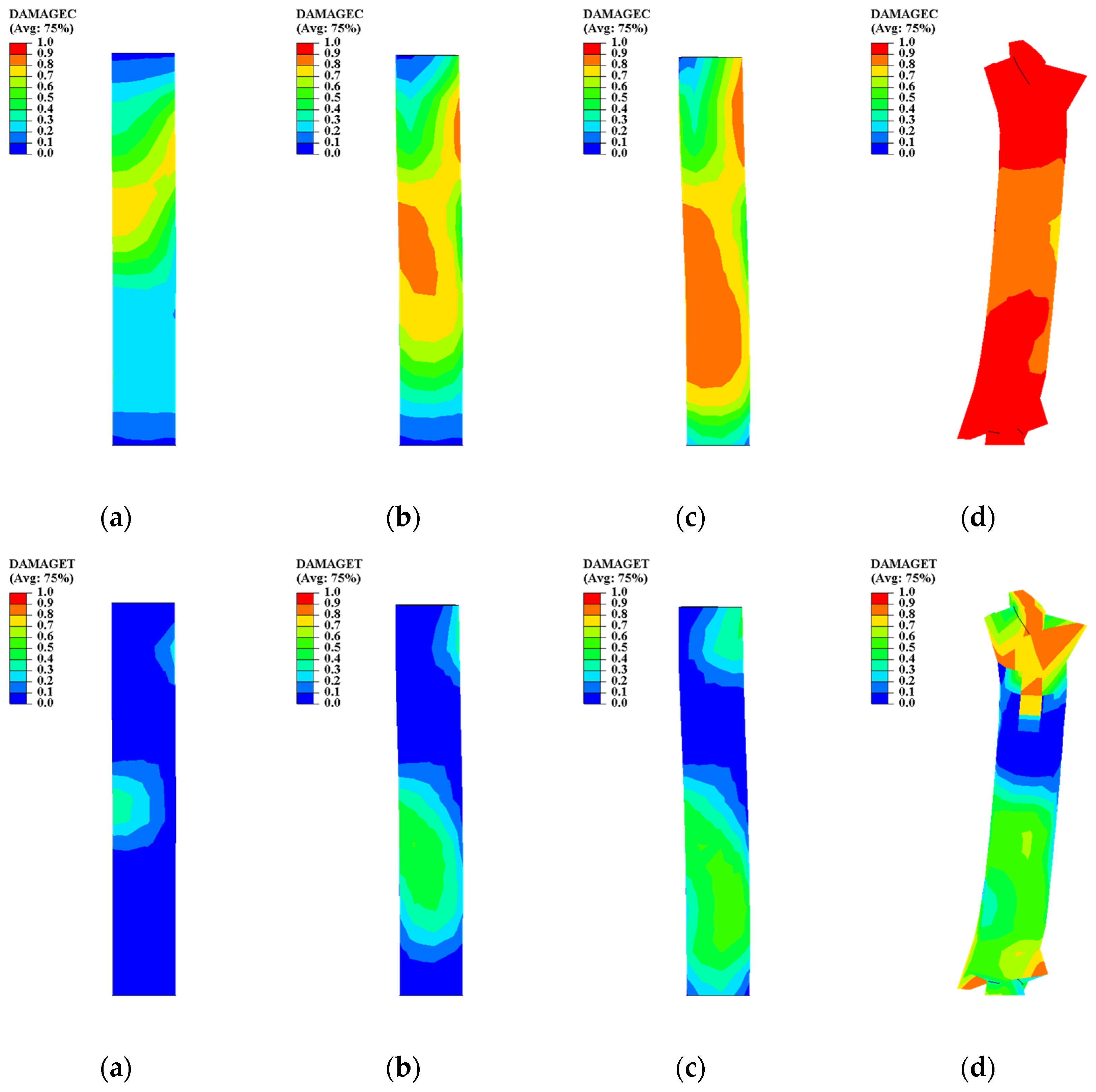
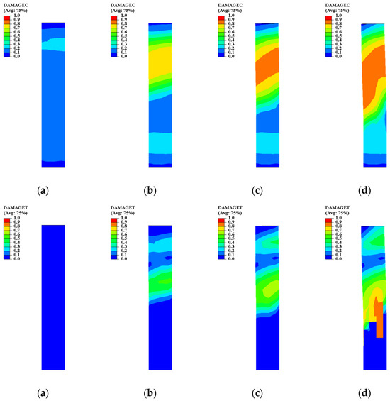
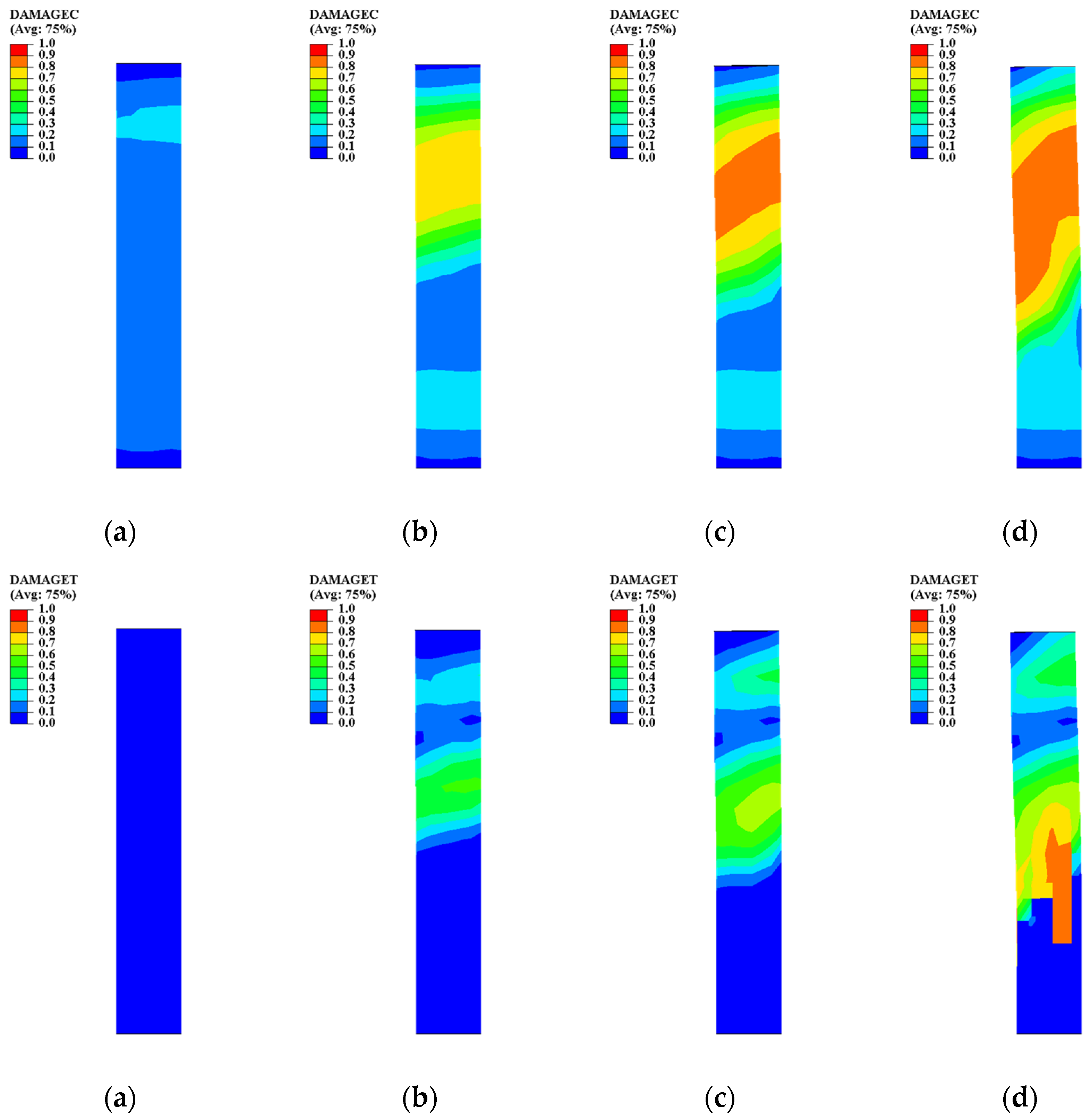
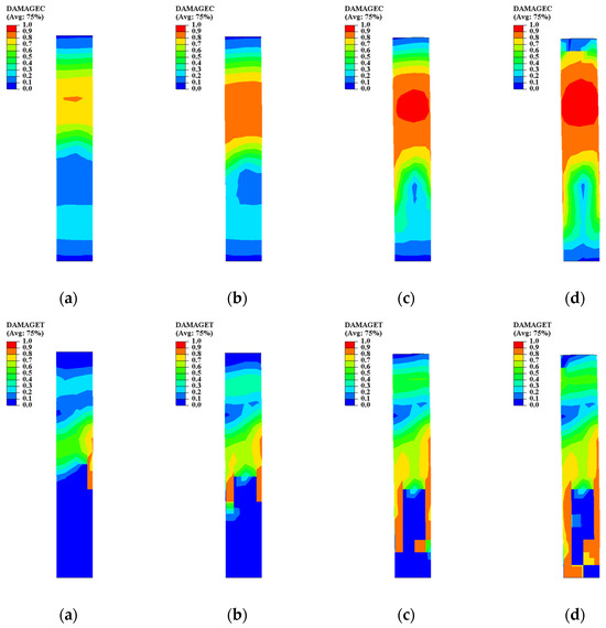
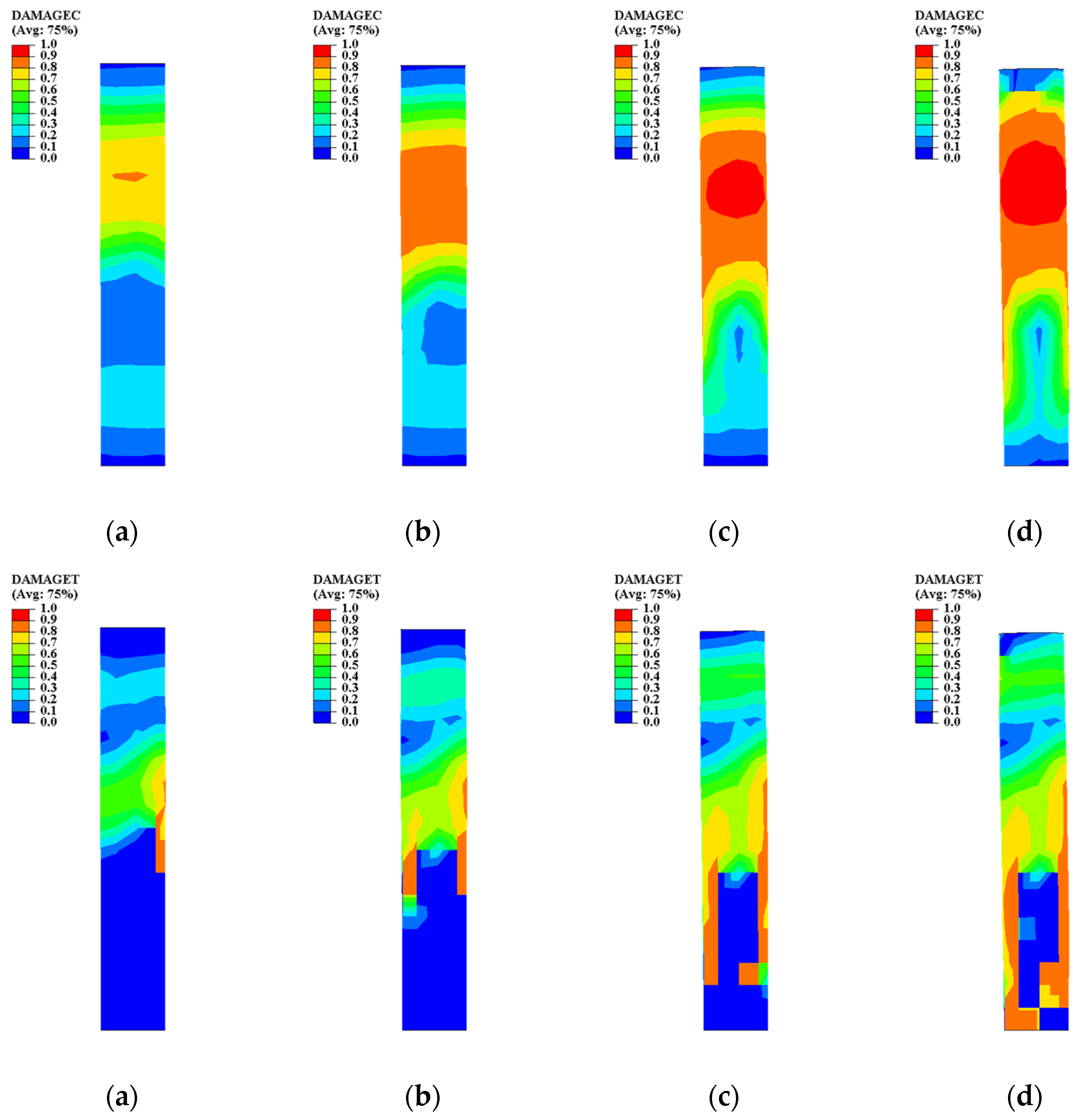
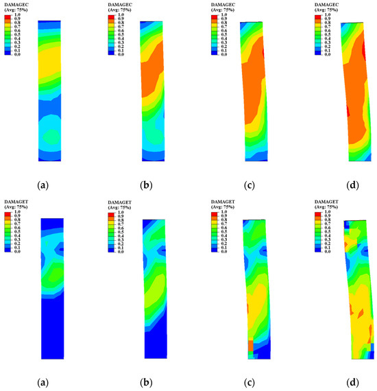
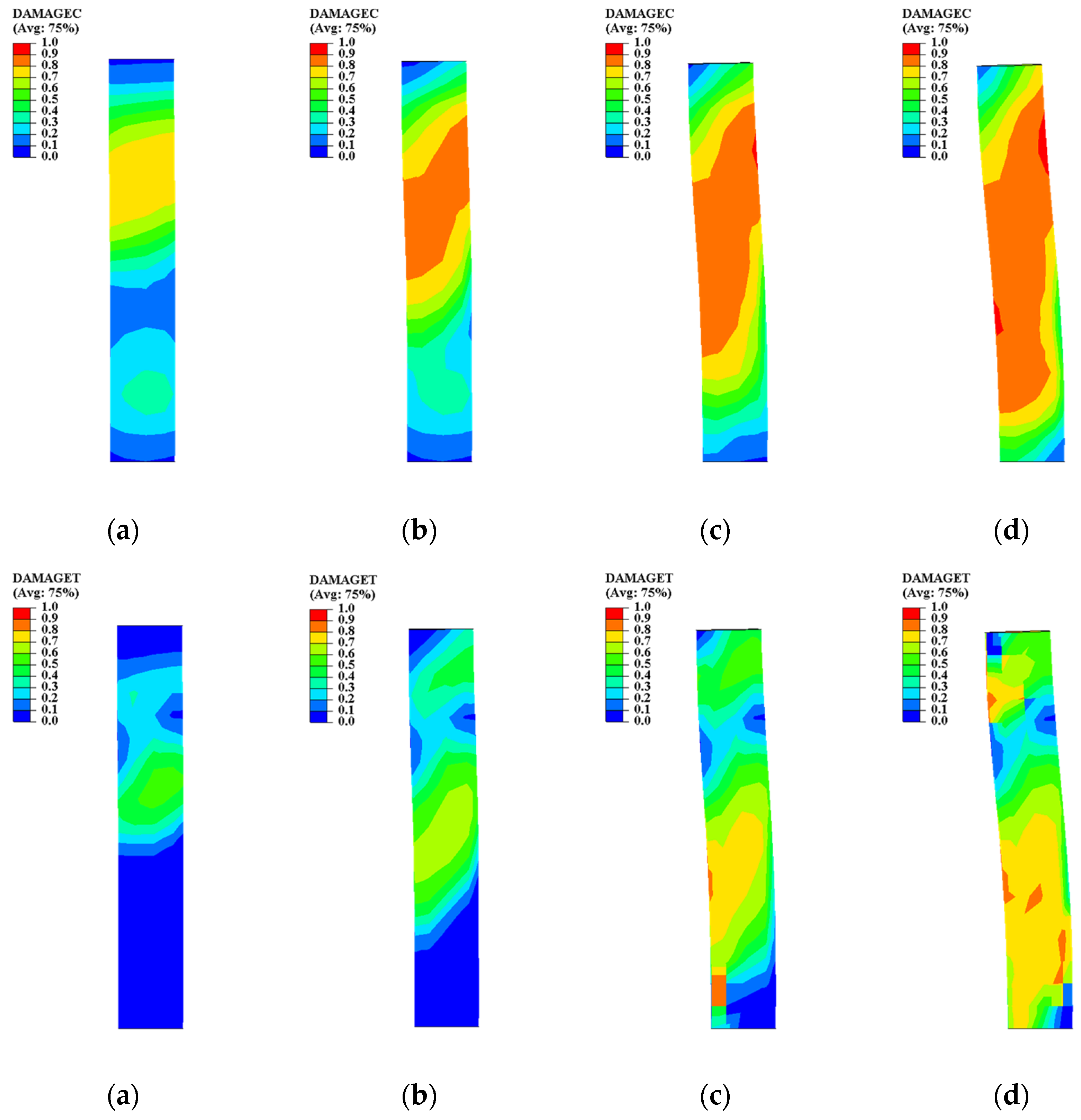
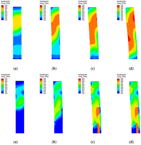
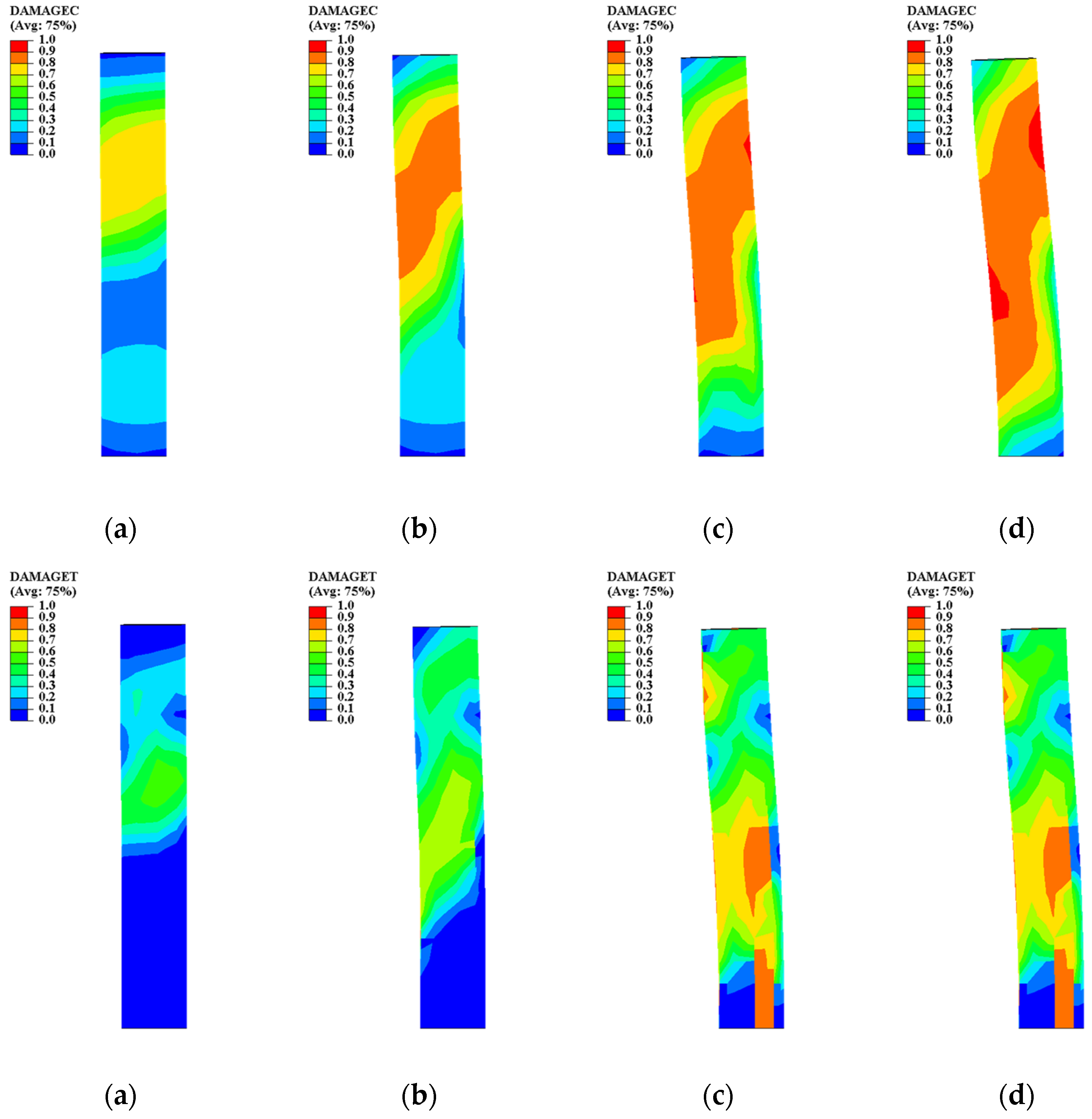
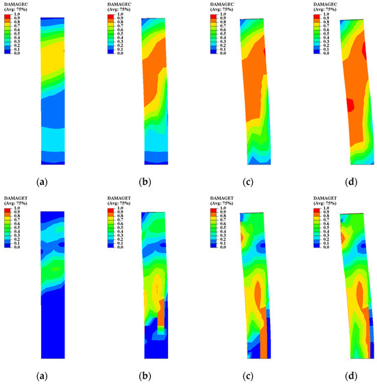
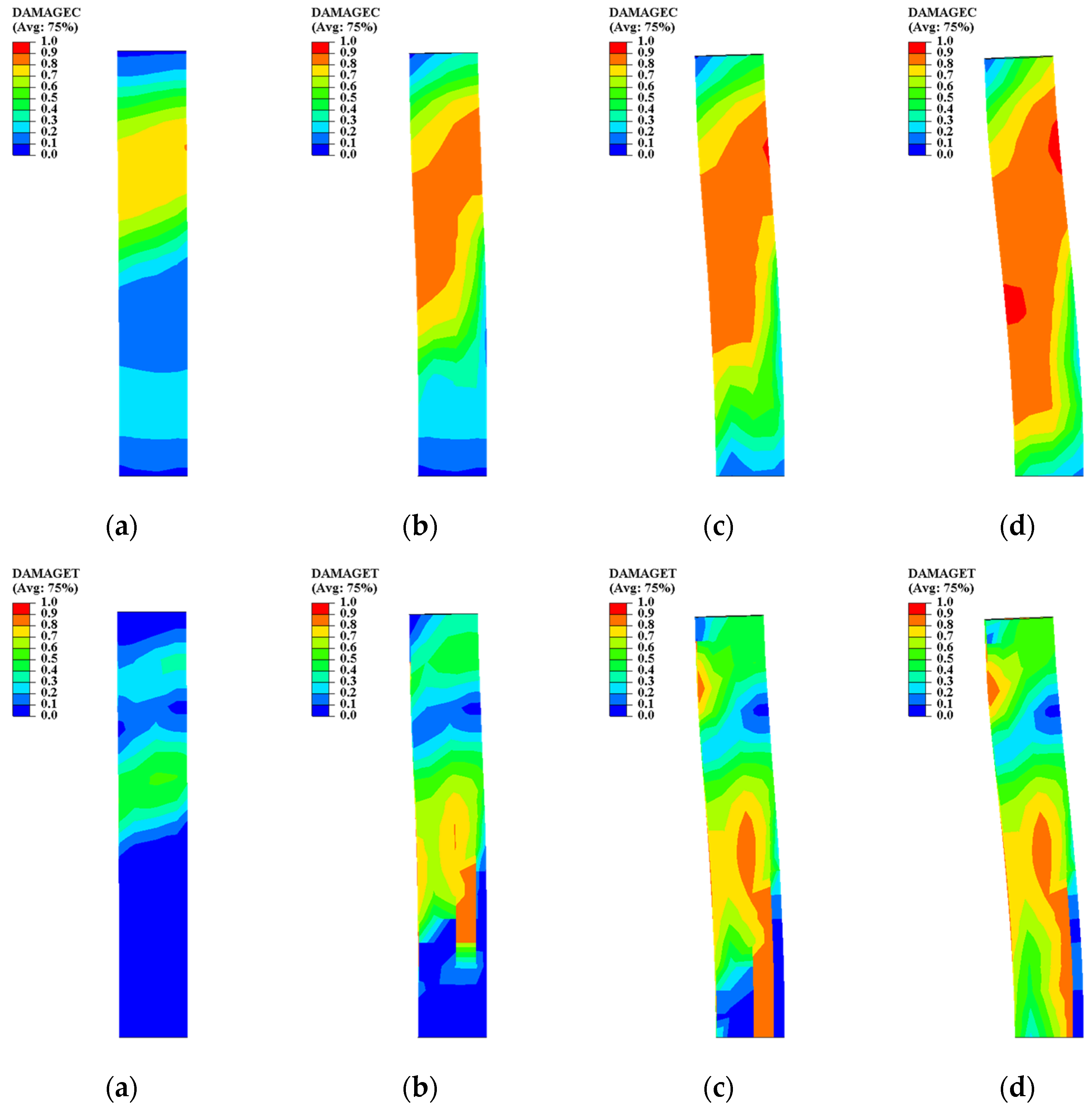
The evolution of concrete damage provides additional insight into the confinement mechanism of the composite columns. Figure 24, Figure 25, Figure 26, Figure 27, Figure 28 and Figure 29 present the tensile damage (DAMAGET) and compressive damage (DAMAGEC) distributions of the concrete core at increasing axial displacements.
Figure 24.
Concrete compressive damage of Specimen 7: (a) Axial displacement: 5 mm; (b) Axial displacement: 10 mm; (c) Axial displacement: 15 mm; (d) Axial displacement: 20 mm.
Figure 25.
Concrete compressive damage of Specimen 8: (a) Axial displacement: 5 mm; (b) Axial displacement: 10 mm; (c) Axial displacement: 15 mm; (d) Axial displacement: 20 mm.
Figure 26.
Concrete compressive damage of Specimen 9: (a) Axial displacement: 5 mm; (b) Axial displacement: 10 mm; (c) Axial displacement: 15 mm; (d) Axial displacement: 20 mm.
Figure 27.
Concrete compressive damage of Specimen 10: (a) Axial displacement: 5 mm; (b) Axial displacement: 10 mm; (c) Axial displacement: 15 mm; (d) Axial displacement: 20 mm.
Figure 28.
Concrete compressive damage of Specimen 11: (a) Axial displacement: 5 mm; (b) Axial displacement: 10 mm; (c) Axial displacement: 15 mm; (d) Axial displacement: 20 mm.
Figure 29.
Concrete compressive damage of Specimen 12: (a) Axial displacement: 5 mm; (b) Axial displacement: 10 mm; (c) Axial displacement: 15 mm; (d) Axial displacement: 20 mm.
At the early loading stage (5 mm), both tensile and compressive damage remained limited and mainly appeared as scattered low-level zones. The damage distribution was relatively uniform, indicating that the concrete core still worked in a largely elastic state and effectively shared the axial load with the steel tube.
As the displacement increased to 10 mm, compressive damage began to concentrate near the mid-height of the column. This region corresponded to the onset of steel tube yielding and local instability observed in the stress contours. The confinement from the steel tube delayed the formation of severe compressive crushing, allowing the damaged zone to expand gradually rather than localizing immediately. Meanwhile, tensile damage remained minor and was primarily associated with lateral dilation of the concrete core.
At 15 mm displacement, the compressive damage evolved into a continuous band, especially in specimens with larger diameter–thickness ratios. The damaged region aligned with the inclined plastic zones of the steel tube, indicating a strong interaction between steel shell buckling and concrete crushing. In the concrete-filled specimens with moderate confinement, the damaged area spread over a wider region instead of forming a single crushing core. This distributed damage pattern suggests improved energy absorption and deformation capacity.
When the displacement reached 20 mm, severe compressive damage dominated the failure region. In some specimens, the damage factor approached unity, indicating near-complete loss of compressive stiffness in localized zones. However, the steel tube confinement prevented catastrophic spalling and maintained overall structural integrity. Tensile damage also became more visible, especially near the outer regions of the concrete core, reflecting dilation-induced cracking during large plastic deformation.
A comparison among specimens shows that stronger confinement (lower diameter–thickness ratio and higher steel strength) resulted in more distributed compressive damage and delayed crushing. In contrast, weakly confined specimens exhibited rapid damage localization and early loss of load-carrying capacity. The interaction between steel yielding and concrete damage governed the post-peak behavior: once the steel tube entered localized buckling, the concrete core experienced accelerated crushing, which in turn intensified steel instability.
3.3.5. Overall Discussion
The evolution of the stress contours demonstrates that the failure behavior of the columns is governed by the interaction between shell stability and material plasticity. Hollow specimens are dominated by local buckling, characterized by inclined plastic bands and end localization. Concrete infill effectively restrains buckling, promotes distributed plasticity, and improves deformation stability. In contrast, higher steel strength increases load capacity but accelerates stress localization once yielding occurs.
The combined influence of diameter–thickness ratio, concrete confinement and steel strength controls the balance between strength and ductility. A moderate diameter–thickness ratio with concrete confinement provides the most stable plastic development and favorable post-peak behavior.
The combined stress and damage analyses reveal a coupled failure mechanism. The steel tube provides lateral confinement that restrains concrete dilation, while the concrete core stabilizes the steel shell and delays local buckling. During loading, plastic deformation in the steel tube transfers additional confinement pressure to the concrete, promoting distributed damage rather than brittle crushing. Once either component loses stability, the other rapidly deteriorates, leading to localized collapse. Therefore, the balance between steel shell stability and concrete confinement is the key factor controlling the strength and ductility of CFST stub columns.
3.4. Structural Performance Evaluation Under Monotonic Compression
3.4.1. Load Enhancement Effect of Concrete Confinement
To evaluate the strengthening effect of the concrete core, the axial load enhancement ratio was defined as
where NCFST and NCHST represent the peak loads of the concrete-filled and hollow steel tube specimens with identical geometric parameters.
The calculated results show that concrete infill significantly increased the axial capacity. The enhancement ratio increased with increasing diameter–thickness ratio, indicating that the relative contribution of the concrete core becomes more significant for more slender steel tubes. This confirms that confinement efficiency is a key parameter governing composite action.
3.4.2. Initial Stiffness Comparison
The initial axial stiffness was evaluated from the slope of the load–displacement curve in the elastic stage. Concrete-filled specimens exhibited noticeably higher stiffness than hollow tubes. The presence of the concrete core increased axial rigidity and delayed the onset of instability.
Specimens with higher steel strength showed only marginal stiffness improvement, suggesting that stiffness is primarily controlled by composite action rather than steel yield strength.
3.4.3. Post-Peak Stability
Post-peak stability was assessed by examining the descending branch of the load–displacement curves. Hollow steel tubes showed rapid strength degradation once local buckling occurred. In contrast, concrete-filled specimens demonstrated a gradual load reduction and sustained resistance over a larger displacement range.
This behavior indicates that the concrete core stabilizes the steel shell and prevents abrupt collapse. Specimens with moderate diameter–thickness ratios achieved the smoothest post-peak response, reflecting a favorable balance between confinement and flexibility.
3.4.4. Deformation Capacity
The deformation capacity was quantified using the displacement ratio
where δy corresponds to peak load and δu is defined at 85% post-peak strength. The 85% post-peak criterion has been commonly adopted in studies of confined concrete and CFST members under monotonic compression as a practical failure definition, ensuring consistency with experimental practice and structural evaluation methods.
Concrete-filled specimens consistently exhibited larger deformation capacity than hollow specimens. Increasing steel strength improved peak load but did not significantly enhance deformation stability. Excessive diameter–thickness ratios reduced ductility due to early shell buckling.
3.4.5. Failure Mode Classification
Based on stress and damage contours, the failure modes can be categorized into:
(1) Local buckling dominated collapse (thin hollow tubes);
(2) Confined plastic crushing (CFST with moderate D/t);
(3) End-localized plastic instability (high-strength steel).
These classifications highlight the interaction between shell stability and concrete confinement.
3.4.6. Comparison with Design Code Predictions
To evaluate the conservatism and engineering relevance of the numerical results, the peak axial capacities obtained from FE analysis were compared with the design-oriented predictions provided by EN 1994-1-1 (EC4) [39] and AISC 360 [40].
According to EC4, the plastic resistance of a composite section under axial compression may be expressed as
where As = cross-sectional area of steel tube, Ac = area of concrete core, fy/γa = design yield strength of steel, and αccfck/γc = design compressive strength of concrete. In the present comparison, γa = 1.0, αcc = 0.85, and γc =1.5 were adopted to obtain a baseline design-level prediction.
According to AISC 360 provisions for composite compression members, the nominal axial resistance may be estimated as follows:
The comparison results between FE predictions and code-based capacities are summarized in Table 3. It can be observed that: (1) for CHST specimens, FE capacities are approximately 1.02–1.28 times the EC4 predictions, and (2) for CFST specimens, FE capacities are 1.33–1.82 times the EC4 predictions and 1.25–1.55 times the AISC nominal predictions.
Table 3.
Summary of structural performance indices under monotonic compression.
The deviation observed in CFST specimens is mainly attributed to the following: (1) the simplified confinement representation in design equations; (2) the inability of code expressions to explicitly capture progressive composite interaction and contact-driven confinement development; and (3) the absence of strain hardening effects in simplified code formulations.
Therefore, the numerical results may be regarded as representing the achievable structural response under idealized material interaction conditions, whereas EC4 and AISC provide conservative design-oriented predictions.
Importantly, although absolute values differ, the parametric trends identified in the FE study—such as the influence of D/t ratio and steel strength—remain compatible with the logic embedded in current design codes.
4. Conclusions
Based on finite element analyses of hollow and concrete-filled steel tube stub columns under monotonic axial compression, the following conclusions can be drawn:
- The collapse of hollow steel tube columns is governed by local shell buckling characterized by inclined plastic bands and end-region localization. In contrast, concrete-filled specimens exhibit distributed plastic development due to confinement, which delays instability and stabilizes the post-peak response.
- The concrete core significantly enhances axial capacity and deformation stability. The confinement effect restrains inward buckling of the steel tube and promotes a more uniform stress redistribution, resulting in improved post-peak performance compared with hollow tubes.
- Increasing the diameter–thickness ratio accelerates local instability and reduces deformation capacity. Specimens with moderate diameter–thickness ratios achieve the most favorable balance between strength and stability, highlighting the importance of shell confinement efficiency.
- Higher steel yield strength increases peak load capacity but does not proportionally enhance deformation capacity. Plastic zones tend to become more localized with increasing strength, and once local buckling initiates, post-peak degradation progresses more rapidly. The response is therefore governed by instability-driven localization rather than material fracture.
- The structural behavior of CFST columns is governed by a coupled mechanism between steel shell stability and concrete damage evolution. Effective confinement enables distributed crushing of the concrete core while stabilizing steel plasticity, which is essential for achieving robust compressive performance.
These findings provide insight into the design of composite steel–concrete columns and emphasize that optimal performance is achieved through balanced confinement rather than strength enhancement alone.
It should be noted that the present study is limited to stub columns subjected to monotonic concentric axial compression, where the structural response is primarily governed by material nonlinearity and local buckling. The findings cannot be directly generalized to slender columns dominated by global instability or to members under eccentric loading involving bending–compression interaction. Future studies will extend the validated numerical framework to investigate stability–confinement interaction and second-order effects in slender and eccentrically loaded CFST members, thereby broadening the applicability of the present conclusions.
Author Contributions
Conceptualization, Y.W., F.Z., M.T. and H.X.; methodology, Y.W.; software, Y.W.; validation, Y.W., S.Z. and M.T.; formal analysis, Y.W.; investigation, Y.W.; resources, F.Z.; data curation, Y.W.; writing—original draft preparation, Y.W.; writing—review and editing, F.Z., S.Z., H.X. and D.L.; visualization, Y.W.; supervision, F.Z. and M.T.; project administration, F.Z.; funding acquisition, D.L. All authors have read and agreed to the published version of the manuscript.
Funding
This research was funded by the China Post-doctoral Science Foundation Funded Project, Grant No. 2024M753652.
Data Availability Statement
The original contributions presented in this study are included in the article. Further inquiries can be directed to the corresponding author.
Conflicts of Interest
Author Yao Wang, Shufeng Zhang, Feng Zhang, Minjie Tu, and Hongguang Xu were employed by CSCEC Strait Construction and Development Co., Ltd., Fuzhou, China. The remaining author declares that the research was conducted in the absence of any commercial or financial relationships that could be construed as a potential conflict of interest. The company had no role in the design of the study; in the collection, analysis, or interpretation of data; in the writing of the manuscript; or in the decision to publish the results.
Abbreviations
The following abbreviations are used in this manuscript:
| CFST | Concrete-filled steel tube |
| CHST | Hollow steel tubes |
| D/t | Diameter-to-thickness ratio |
| FE | Finite element |
| CDP | Concrete Damaged Plasticity |
| RP | Reference point |
| N | The axial load capacity |
| δ | The axial displacement |
| N–δ | Global axial load–displacement relationship |
| DAMAGET | The tensile damage |
| DAMAGEC | The compressive damage |
References
- Schneider, S.P. Axially loaded concrete-filled steel tubes. J. Struct. Eng. 1998, 124, 1125–1138. [Google Scholar] [CrossRef] [Scilit]
- Uy, B. Strength of concrete filled steel box columns incorporating local buckling. J. Struct. Eng. 2000, 126, 341–352. [Google Scholar] [CrossRef] [Scilit]
- Hong, H.P.; Yuan, H.; Deng, L.; Bai, Y. Axial capacity of steel tube-reinforced concrete stub columns. Eng. Struct. 2019, 183, 523–532. [Google Scholar] [CrossRef] [Scilit]
- Lu, H.; Han, L.H.; Zhao, X.L. Analytical behavior of circular concrete-filled thin-walled steel tubes subjected to bending. Thin Walled Struct. 2009, 47, 346–358. [Google Scholar] [CrossRef] [Scilit]
- Theofanous, M.; Gardner, L. Testing and numerical modelling of lean duplex stainless steel hollow section columns. Eng. Struct. 2009, 31, 3047–3058. [Google Scholar] [CrossRef] [Scilit]
- Katwal, U.; Tao, Z.; Hassan, M.K.; Wang, W.-D. Simplified numerical modeling of axially loaded circular concrete-filled steel stub columns. J. Struct. Eng. 2017, 143, 04017169. [Google Scholar] [CrossRef] [Scilit]
- Han, L.H.; Yao, G.H.; Tao, Z. Behaviors of concrete-filled steel tubular members subjected to combined loading. Thin Walled Struct. 2007, 45, 600–619. [Google Scholar] [CrossRef] [Scilit]
- Han, L.H.; Ren, Q.X.; Li, W. Tests on inclined, tapered and STS concrete-filled steel tubular (CFST) stub columns. J. Constr. Steel Res. 2010, 66, 1186–1195. [Google Scholar] [CrossRef] [Scilit]
- Tao, Z.; Han, L.H.; Wang, D.Y. Strength and ductility of stiffened thin-walled hollow steel structural stub columns filled with concrete. Thin Walled Struct. 2008, 46, 1113–1128. [Google Scholar] [CrossRef] [Scilit]
- Li, X.; Cao, R.; Meng, Y. Hysteretic Behavior and Ductility Analysis of Circular Recycled Concrete-Filled Steel Tube Columns Under Low-Cycle Loading. Coatings 2025, 15, 1456. [Google Scholar] [CrossRef] [Scilit]
- Yu, M.; Yao, X.; Xie, K.; Hao, T.; Wang, X. Analysis Method for the Pouring Stage of Concrete-Filled Steel Tube (CFST) Arch Bridges Considering Time-Varying Heat of Hydration and Elastic Modulus. Buildings 2025, 15, 1711. [Google Scholar] [CrossRef] [Scilit]
- Nakahara, H.; Uchida, K.; Yanai, Y. Test and analysis for shearing behavior of circular CFST columns. Buildings 2024, 14, 3871. [Google Scholar] [CrossRef] [Scilit]
- Çelik, A.İ.; Özkılıç, Y.O.; Zeybek, Ö.; Karalar, M.; Qaidi, S.; Ahmad, J.; Burduhos-Nergis, D.D.; Bejinariu, C. Mechanical behavior of crushed waste glass as replacement of aggregates. Materials 2022, 15, 8093. [Google Scholar] [CrossRef] [Scilit]
- Çelik, A.İ.; Özkılıç, Y.O.; Zeybek, Ö.; Özdöner, N.; Tayeh, B.A. Performance assessment of fiber-reinforced concrete produced with waste lathe fibers. Sustainability 2022, 14, 11817. [Google Scholar] [CrossRef] [Scilit]
- Mahgub, M.; Ashour, A.; Lam, D.; Dai, X. Tests of self-compacting concrete filled elliptical steel tube columns. Thin Walled Struct. 2017, 110, 27–34. [Google Scholar] [CrossRef] [Scilit]
- Hamoda, A.; Abdelazeem, F.; Emara, M. Concentric compressive behavior of hybrid concrete–stainless steel double-skin tubular columns incorporating high performance concretes. Thin Walled Struct. 2021, 159, 107297. [Google Scholar] [CrossRef] [Scilit]
- Ozkilic, Y.O.; Madenci, E.; Mansour, W.; Sharaky, I.A.; Fayed, S. Behavior of self-compacting recycled concrete filled aluminum tubular columns under concentric compressive load. Steel Compos. Struct. 2024, 51, 243–260. [Google Scholar] [CrossRef]
- Megahed, K.; Mahmoud, N.S.; Abd-Rabou, S.E.M. Finite Element Modeling for Concrete-Filled Steel Tube Stub Columns under Axial Compression. Int. J. Steel Struct. 2024, 24, 1229–1250. [Google Scholar] [CrossRef] [Scilit]
- Simoncelli, M.; Pisani, M.A.; Bernuzzi, C.; Zucca, M.; Alibeigibeni, A.; Stochino, F. Finite element simulation of composite slabs with recycled concrete aggregates: Collapse mechanisms and interface behaviour. Mater. Struct. 2026, 59, 17. [Google Scholar] [CrossRef] [Scilit]
- Guo, Y.; Wang, M. Experimental study on mechanical behavior and resilient performance of steel frame connection with low-yield-point steel fuses. Eng. Struct. 2022, 266, 114599. [Google Scholar] [CrossRef] [Scilit]
- Hu, X.; Albareda, A.; Bu, X.; López-Almansa, F. Numerical analysis of the axial-flexural behavior of CFST columns with active transverse prestressing. Buildings 2023, 13, 2411. [Google Scholar] [CrossRef] [Scilit]
- Wang, M.; Guo, Y.; Yang, L. Damage indices and fragility assessment of coupled low-yield-point steel plate shear walls. J. Build. Eng. 2021, 42, 103010. [Google Scholar] [CrossRef] [Scilit]
- Lu, D.; Chen, Z.; Ding, F.; Chen, Z.; Sun, P. Prediction of mechanical properties of the stirrup-confined rectangular CFST stub columns using FEM and machine learning. Mathematics 2021, 9, 1643. [Google Scholar] [CrossRef] [Scilit]
- Jones, N. Structural Impact, 2nd ed.; Cambridge University Press: Cambridge, UK, 2012. [Google Scholar]
- Abramowicz, W.; Jones, N. Dynamic axial crushing of square tubes. Int. J. Impact Eng. 1984, 2, 179–208. [Google Scholar] [CrossRef] [Scilit]
- Ban, H.Y.; Shi, G.; Shi, Y.J.; Wang, Y.Q. Research progress on the mechanical property of high strength structural steels. Adv. Mater. Res. 2011, 250, 640–648. [Google Scholar] [CrossRef] [Scilit]
- Shi, G.; Wang, M.; Bai, Y.; Wang, F.; Shi, Y.; Wang, Y. Experimental and modeling study of high-strength structural steel under cyclic loading. Eng. Struct. 2012, 37, 1–13. [Google Scholar] [CrossRef] [Scilit]
- Ellobody, E.; Young, B.; Lam, D. Behaviour of normal and high strength concrete-filled compact steel tube circular stub columns. J. Constr. Steel Res. 2006, 62, 706–715. [Google Scholar] [CrossRef] [Scilit]
- Tao, Z.; Han, L.H.; Wang, D.Y. Experimental behaviour of concrete-filled stiffened thin-walled steel tubular columns. Thin Walled Struct. 2007, 45, 517–527. [Google Scholar] [CrossRef] [Scilit]
- Han, L.H.; Yao, G.H.; Tao, Z. Performance of concrete-filled thin-walled steel tubes under pure torsion. Thin Walled Struct. 2007, 45, 24–36. [Google Scholar] [CrossRef] [Scilit]
- Hou, C.C.; Han, L.H. Life-cycle performance of deteriorated concrete-filled steel tubular (CFST) structures subject to lateral impact. Thin Walled Struct. 2018, 132, 362–374. [Google Scholar] [CrossRef] [Scilit]
- Zhao, H.; Wang, R.; Hou, C.C.; Lam, D. Performance of circular CFDST members with external stainless steel tube under transverse impact loading. Thin Walled Struct. 2019, 145, 106380. [Google Scholar] [CrossRef] [Scilit]
- Guo, Y.; Wang, M. Resilient performance of steel connections with low yield point fuses considering the effect of RC floor slab. Structures 2023, 57, 105219. [Google Scholar] [CrossRef] [Scilit]
- Yang, Y.F.; Zhang, Z.C.; Fu, F. Experimental and numerical study on square RACFST members under lateral impact loading. J. Constr. Steel Res. 2015, 111, 43–56. [Google Scholar] [CrossRef] [Scilit]
- Kang, L.; Fan, W.; Liu, B.; Liu, Y. Numerically efficient analysis of concrete-filled steel tubular columns under lateral impact loading. J. Constr. Steel Res. 2021, 179, 106564. [Google Scholar] [CrossRef] [Scilit]
- Yu, P.; Ren, Z.; Yun, W.; Zhao, Y.; Xu, J. Performance of bolt-welded CFST short columns with different initial imperfections: Experimental and numerical studies. Buildings 2022, 12, 1352. [Google Scholar] [CrossRef] [Scilit]
- Da Silva, L.S.; Simões, R.; Gervásio, H. Design of Steel Structures: Eurocode 3: Design of Steel Structures, Part 1-1: General Rules and Rules for Buildings; John Wiley & Sons: Hoboken, NJ, USA, 2012. [Google Scholar]
- Lu, D.; Gong, Y.; Ding, F.; Wang, L.; Deng, C.; Yuan, T.; Luo, C.; Ren, E. Experimental study of square CFST stub columns with a low steel ratio under axial loading. Front. Mater. 2021, 8, 629819. [Google Scholar] [CrossRef] [Scilit]
- ENBS 1-1: 2004; Eurocode 4-Design of Composite Steel and Concrete Structures-Part 1-1: General Rules and Rules for Buildings. British Standards Institution: London, UK, 1994.
- AISC 360-16; Specification for Structural Steel Buildings. AISC: Chicago, IL, USA, 2016.

Disclaimer/Publisher’s Note: The statements, opinions and data contained in all publications are solely those of the individual author(s) and contributor(s) and not of MDPI and/or the editor(s). MDPI and/or the editor(s) disclaim responsibility for any injury to people or property resulting from any ideas, methods, instructions or products referred to in the content. |
© 2026 by the authors. Licensee MDPI, Basel, Switzerland. This article is an open access article distributed under the terms and conditions of the Creative Commons Attribution (CC BY) license.