


Abstract
High-platform timber structures represent a typical structural form in ancient Chinese architecture, where the platform and the upper timber structure constitute a mechanically coupled system with interacting mechanical properties and response behaviors. However, a systematic understanding of their global coupling mechanism and its impact on structural response remains unclear. This study investigates a representative high-platform timber structure, i.e., Xi’an Bell Tower, to analyze the static and dynamic response characteristics of the platform–superstructure system using in situ dynamic testing and finite element simulation. The results indicate that the simulated first two natural frequencies align well with in situ measurements, validating the model’s rationality. The global coupling effect alters the system’s mass and stiffness distribution, leading to an overall lengthening of the structural natural periods. Structural self-weight is identified as the dominant factor inducing vertical deformation under serviceability conditions, with significant deformation observed at the platform’s edges and corners. Under lateral loads, deformations concentrate in the second story of the timber superstructure, with seismic actions exerting a more pronounced influence than wind loads. Under rare earthquake conditions, the maximum inter-story drift ratio reaches 1/70. Local tensile stresses at the joints, architrave ends, and the Dou-Gong layer exceed the timber’s tensile strength parallel to the grain, identifying these components as the weak links in the structure’s seismic performance.
1. Introduction
High-platform timber structures constitute a distinct architectural typology within ancient Chinese construction, widely prevalent in city towers, bell and drum towers, and palace complexes. The Xi’an Bell Tower serves as a quintessential representative of this structural form [1,2]. However, having endured centuries of environmental weathering and continuous service loading, these historical structures inevitably face multiple threats, including material degradation, loosening of joints, and cumulative damage. Consequently, their structural performance has been significantly altered [3,4,5]. In particular, under natural hazards such as seismic excitations and extreme wind loads, the structural safety is severely challenged. Therefore, an in-depth investigation into the dynamic response of such high-platform timber structures under various hazard environments is of great significance for the preventive conservation of ancient architecture [6,7].
With the advancement of finite element (FE) technology, numerical simulation has emerged as a primary approach for evaluating the structural performance of ancient architecture [8]. Currently, refined modeling methodologies for key components—such as mortise-tenon joints [9], Dou-Gong brackets [10,11] and column bases [12]—have been extensively applied to the seismic performance assessment of global structures. Researchers have effectively evaluated the structural performance of ancient architectures, such as Ming Dynasty limestone halls [13] and ancient masonry pagodas [14], by employing in situ investigations and numerical simulations. Furthermore, researchers have analyzed the dynamic response of structures by establishing three-dimensional finite element models of global timber structures, investigating the global deformation patterns and collapse mechanisms under seismic actions, and assessing their damage characteristics under earthquake loading [15,16]. These studies provide a scientific basis for the protection of existing traditional timber structures.
Previous studies on the coupling interaction between the platform (specifically the internal soil core) and the superstructure have revealed that the behavior of the superstructure is significantly influenced by the underlying platform. In particular, the high-platform exerts a substantial impact on the higher-order frequencies of the upper timber structure and leads to an amplification of its seismic response [17,18]. While the mechanical behaviors of timber superstructures have been extensively characterized, the research on the composite ‘high-platform–timber structure’ system lacks a holistic perspective. A synthesis of existing literature reveals a prevalent methodological limitation: most studies decouple the superstructure from the substructure, treating the platform merely as a rigid boundary condition [19,20]. This assumption fundamentally ignores the soil-structure interaction (SSI) and the amplification effects inherent to the high platform. By neglecting the deformation compatibility between the masonry-rammed earth platform and the timber frame, such simplified models tend to underestimate lateral displacements and overlook differential settlements that are critical for structural safety. Specifically, while the independent behaviors of the timber frame and the masonry high-platform are reasonably understood, a gap remains in the quantitative understanding of their dynamic coupling mechanism—particularly regarding how the flexibility of the high-platform induces period elongation and alters the vibration modes of the superstructure. Furthermore, existing literature predominantly focuses on seismic scenarios. However, tall timber structures are also highly sensitive to wind loads [21,22]. There is currently a lack of comprehensive comparative assessment regarding structural responses under wind loads and other combined loading conditions, which limits the complete understanding of their response characteristics.
In this study, the Xi’an Bell Tower is taken as the research object. Unlike previous studies that simplified the high-platform as a rigid base, this paper investigates the overall dynamic interaction through a systematic research workflow. First, field testing data and existing literature were synthesized to determine material parameters. Second, a holistic FE model was developed, incorporating the internal rammed earth core, the external masonry platform, and the upper timber superstructure. Third, model validation was conducted to ensure numerical accuracy. Finally, comprehensive static, wind, and seismic analyses were performed to identify vulnerable zones under various load combinations and to comparatively evaluate the effects on lateral stiffness and structural stability.
2. Structural Description and Dynamic Testing
2.1. Description of the Xi’an Bell Tower
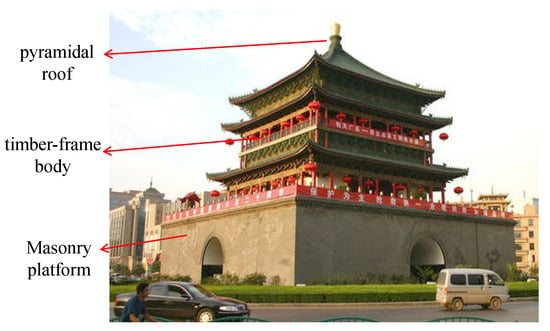
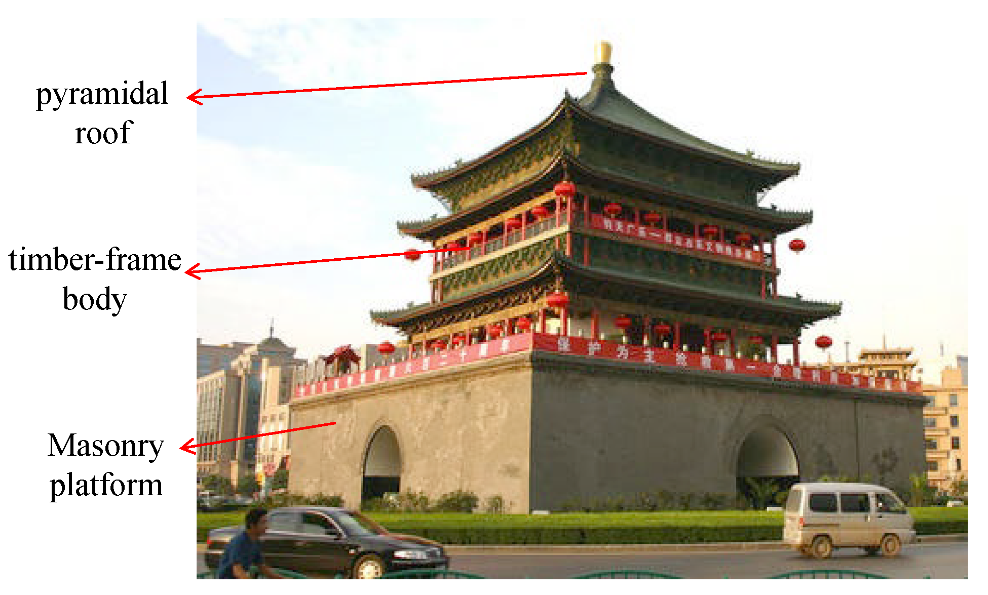
Originally constructed in the 17th year of the Hongwu reign (1384) and relocated to its current site in the 10th year of the Wanli reign (1582), the Xi’an Bell Tower stands as one of the largest and best-preserved ancient timber structures from the Ming Dynasty in China. As illustrated in Figure 1, the rammed earth tunnels at the base of the Bell Tower feature a symmetrical cruciform layout, while the upper timber superstructure consists of two stories. The structure has a total height of 36.0 m and comprises three distinct components: a masonry platform at the base, a two-story timber frame body in the middle, and a pyramidal roof at the top. The overall configuration exhibits a typical Ming architectural style characterized by “triple eaves and a four-corner pyramidal roof”. The Bell Tower features a symmetric plan layout. The bottom platform is square in plan, with a side length of 35.5 m and a height of 8.6 m. The platform consists of an internal rammed earth core encapsulated by external gray masonry brickwork. A cross-shaped arched tunnel, with both height and width measuring 6.0 m, penetrates the center of the platform. The upper body utilizes a traditional timber frame, forming a composite structural system described as a “high-platform timber tower.”.
Figure 1.
The Xi’an Bell Tower.
Structural loads are primarily transferred through load-bearing timber columns. These columns are interconnected longitudinally and transversely by beams and tie beams with large depth-to-span ratios, creating a spatial framework with significant lateral stiffness. Furthermore, the column bases are inserted into stone plinths equipped with mortises (commonly referred to as “sea eyes”) via tube-foot tenons. This semi-rigid connection restricts horizontal sliding at the column base while permitting slight rocking motions of the column body under strong seismic excitations. Mortise-tenon joints are employed at beam-column intersections. These semi-rigid connections facilitate a certain degree of rotational and compressive deformation between components. Additionally, the dense arrangement of Dou-Gong brackets beneath the eaves not only serves to cantilever the eaves and transfer roof loads but also contributes to seismic energy dissipation through frictional sliding between the interlocking components.
2.2. Dynamic Characteristics Testing
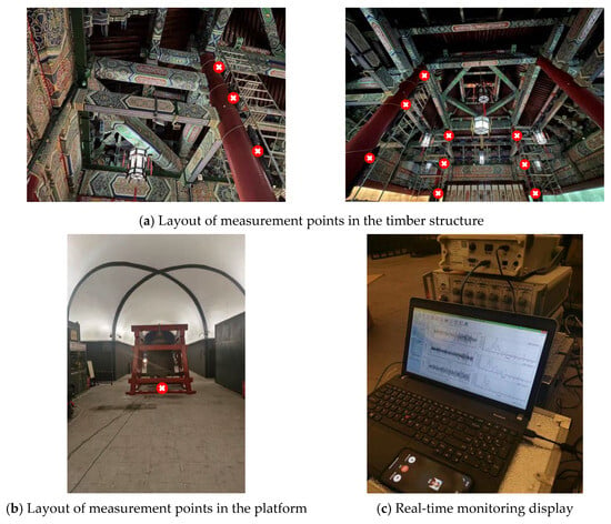
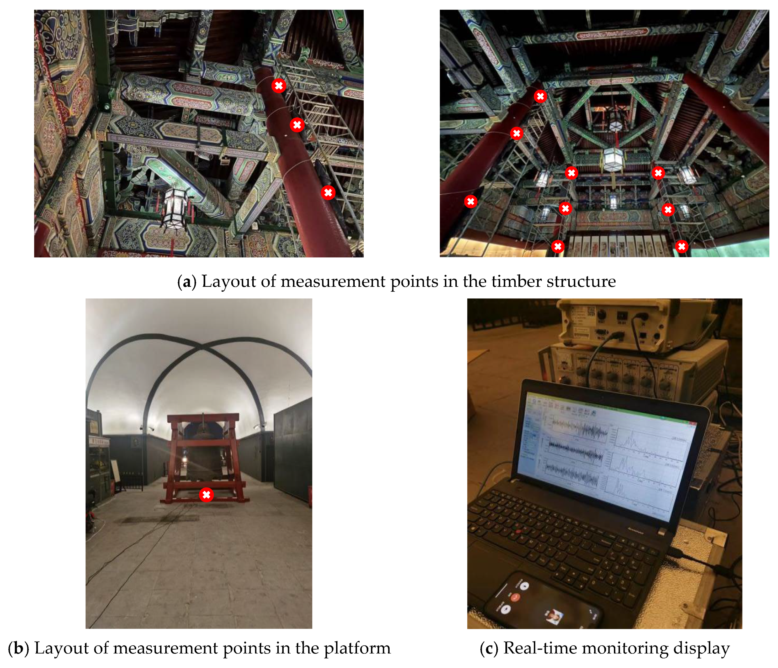
To provide a basis for structural seismic performance assessment and vibration evaluation, in situ dynamic testing was conducted on the Bell Tower, as shown in Figure 2. Figure 2a illustrates the monitoring distribution across the two levels of the upper timber superstructure. Figure 2b displays the distribution of monitoring positions at the base of the internal rammed earth tunnels. By monitoring these critical points, vibration data for various parts of the Bell Tower was obtained, laying the foundation for subsequent model comparison. A 941B ultra-low frequency vibration measurement system and a DA1001 dynamic signal acquisition system were employed. Using the structure’s response to random vibration sources (extremely weak ground vibrations caused by human activities like machinery and vehicles, and natural causes like wind and air pressure), the dynamic characteristics were analyzed based on random vibration theory. The testing process was conducted when construction work had ceased and there were no other vibration sources within a 100 m radius. Measurement points were arranged on the platform and the upper timber structure to test dynamic characteristics in the East–West and North–South directions. After low-pass filtering (upper limit: 20 Hz) the signals and applying an exponential window to the vibration recording signals, auto-spectral analysis was performed. The frequencies corresponding to the auto-spectral peaks of each measurement point were averaged to obtain the first two natural frequencies in the East–West and North–South directions, as shown in Table 1.
Figure 2.
In situ testing site.
Table 1.
Frequency testing results of the platform and timber structure.
3. Finite Element Modeling
3.1. Model Establishment
Based on the geometric dimensions obtained from in situ mapping, a finite element model of the Xi’an Bell Tower was established using the SAP2000 V21 software. The model comprises three distinct components:
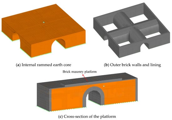
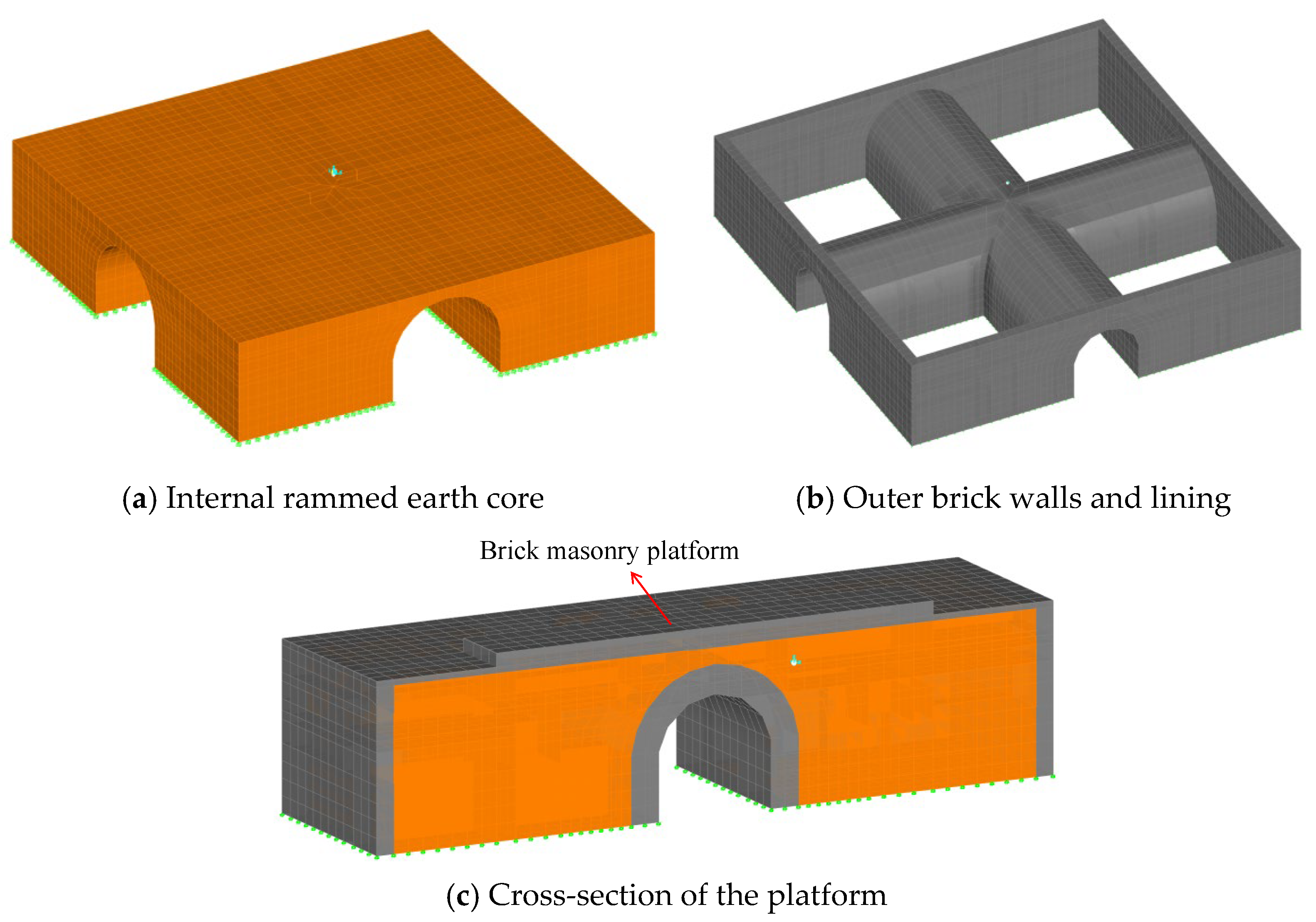
- The lower platform: As illustrated in Figure 3, this component was simulated using 8-node hexahedral solid elements. The core of the platform consists of rammed earth with dimensions of 33,500 mm × 33,500 mm × 8600 mm. Arched tunnels, each measuring 6000 mm in both height and width, penetrate the center of each of the four sides, as shown in Figure 3a. The exterior of the platform and the tunnel linings are constructed of brick masonry, as depicted in Figure 3b. The thickness of the external wall is 900 mm, while the lining thickness is 1450 mm. The interaction between the internal rammed earth core and the surrounding masonry was simulated using node coupling constraints. A 300 mm-thick brick pavement was modeled on top of the rammed earth. On this pavement, a central brick plinth (23,280 mm × 23,280 mm × 680 mm) was established. The cross-section of the platform is presented in Figure 3c.Figure 3. Model of the Xi’an Bell Tower platform.
- 2.
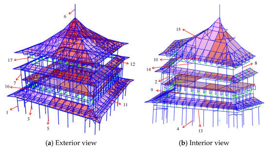
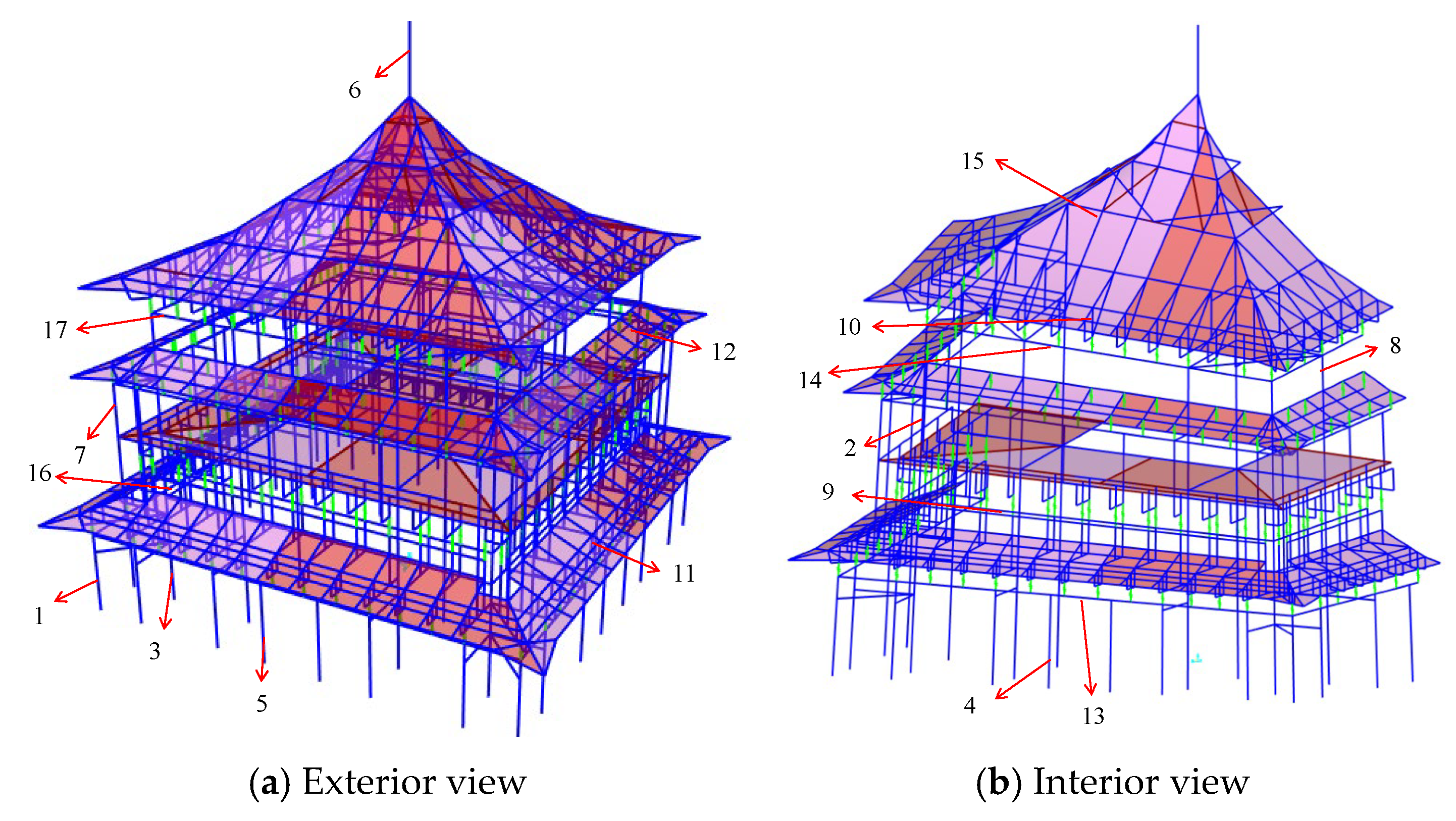
- The timber superstructure: The cross-sectional dimensions of the primary structural members are detailed in Table 2. Structural members such as beams, rafters, tie beams (Fang), and columns were simulated using 2-node beam elements. The Dou-Gong brackets were modeled using spring elements to represent their stiffness characteristics. The roof sheathing and the floor slabs of the second story were simulated using 3-node or 4-node shell elements. The finite element model and the component numbering are illustrated in Figure 4.Table 2. Cross-sectional dimensions of main timber components.Figure 4. Timber structure model of the Bell Tower.
- 3.
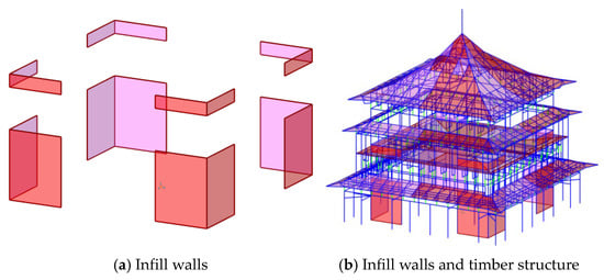
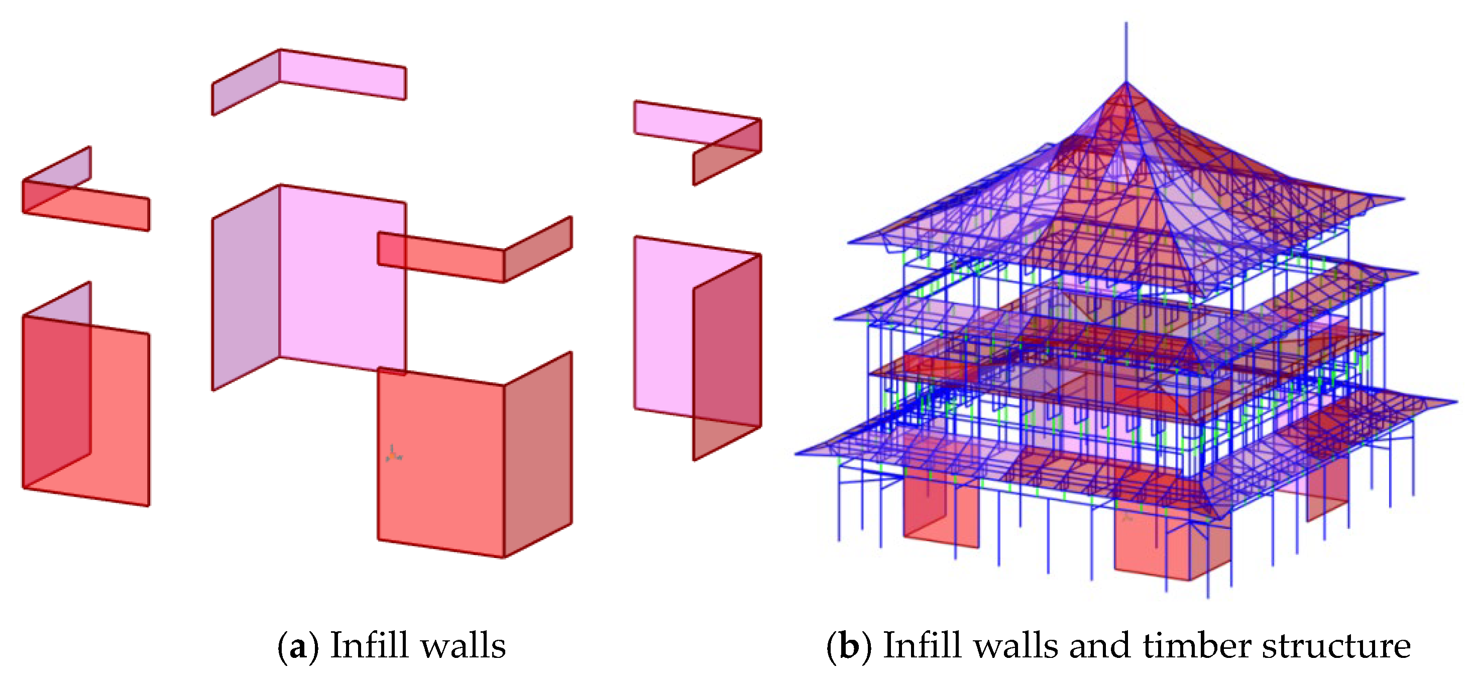
- Non-structural components: As shown in Figure 5. Given the presence of numerous complex non-structural components in ancient timber structures, the masonry infill walls were identified as having the most significant impact on lateral stiffness and mass. Therefore, the modeling of non-structural components in this study primarily focuses on these walls, while other components with minor structural influence were simplified as distributed mass loads applied to the floor slabs. These walls were modeled using 4-node shell elements and are distributed at the four corners of the first and second floors; the wall thickness is 1000 mm on the first floor and 300 mm on the second floor.Figure 5. Masonry infill wall model.
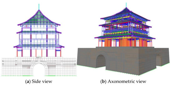
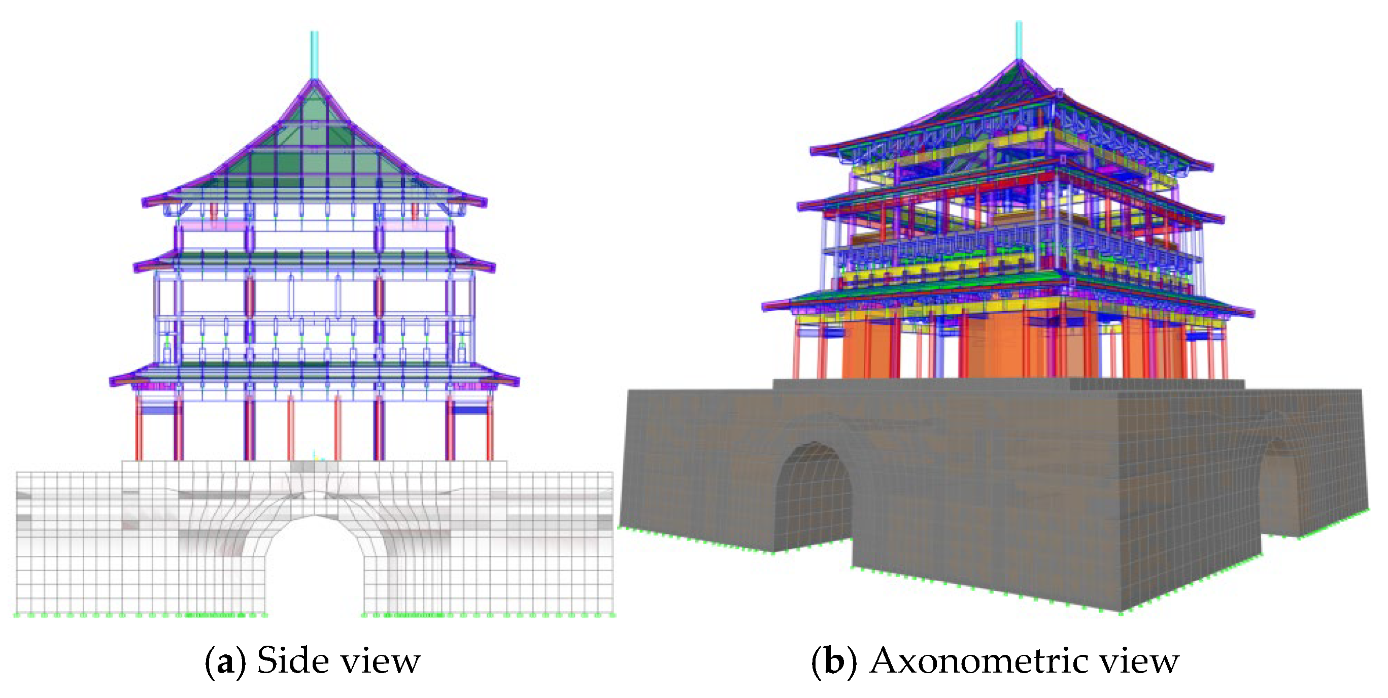
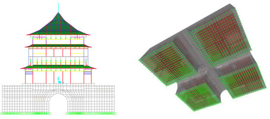
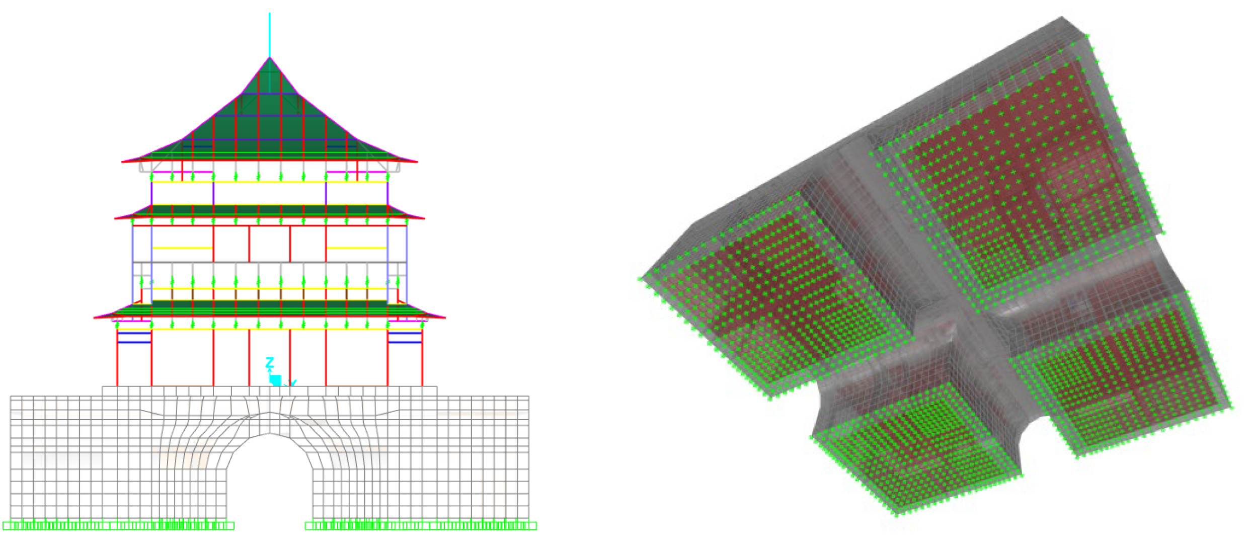
By integrating the models of the platform, the timber superstructure, and the masonry components, the global finite element model of the Xi’an Bell Tower was established, as illustrated in Figure 6.
Figure 6.
Finite element model of the Xi’an Bell Tower.
3.2. Material Parameters
The material properties of the Xi’an Bell Tower were based on in situ research data from the Xi’an East Gate Tower and the Arrow Tower of the North Gate [23,24]. Both towers are located in Xi’an and, like the Bell Tower, are Ming Dynasty structures sharing similar architectural styles and material types. Therefore, the in situ testing results effectively reflect the material degradation properties of this material type and serve as a reliable reference for the model parameters. The specific material parameters are presented in Table 3, where timber was modeled as an orthotropic material.
Table 3.
Material properties.
Extensive Dou-Gong brackets are distributed at the tops of the eave columns and hypostyle columns on both the first and second stories. To facilitate the modeling process, the brackets were classified into two categories: eave column Dou-Gong and hypostyle column Dou-Gong. The actual stiffness of the brackets in the prototype structure was derived based on similitude laws. In the model, the Dou-Gong brackets were simulated using spring connection elements [25], the stiffness parameters of which are listed in Table 4. Since the stiffness values derived from experimental measurements represent the current structural stiffness of the Bell Tower, adopting this measured equivalent stiffness for finite element modeling effectively accounts for the existing conditions at the joints (such as looseness and aging), thereby laying a solid foundation for the accuracy of the model. Their corresponding stiffness parameters are listed in Table 4.
Table 4.
Similarity relationship and stiffness conversion of Dou-Gong joints.
In the timber structure of the Bell Tower, mortise-tenon joints are employed for beam-column connections. Given the complexity of the actual joint configurations, they were categorized into two primary types to facilitate the analysis: (1) Straight tenon: Used for connections between inner and outer columns (i.e., radial beams), primarily consisting of penetrating tie beams (Chuancha Fang). (2) Dovetail tenon: Used for beam-column connections distributed along the structural perimeter (i.e., circumferential beams), mainly including architraves (E Fang).
Mortise-tenon joints exhibit semi-rigid behavior. The stiffness similarity ratio for the joints in the prototype structure was calculated based on the geometric similitude of the beam cross-sections. Since it is challenging to explicitly define the complex moment-rotation relationship to capture the semi-rigid characteristics of each joint, equivalent rotational stiffness parameters were assigned to the beam ends in the model. These parameters are listed in Table 5.
Table 5.
Similarity relationship and stiffness conversion of Mortise-Tenon joints.
3.3. Boundary Conditions
In the model, to simplify computations and avoid overestimating stiffness, based on previous studies [19], the connection between the bottom nodes of the upper timber columns and the top nodes of the lower high-platform was established via node coupling. Specifically, rotational degrees of freedom were released at the column bases, utilizing hinged constraints to simulate the interaction between the timber columns and the stone plinths. A fixed boundary condition was applied to the bottom of the high-platform, as illustrated in Figure 7.
Figure 7.
Bottom boundary conditions.
4. Dynamic Characteristics
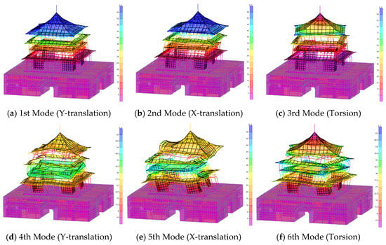
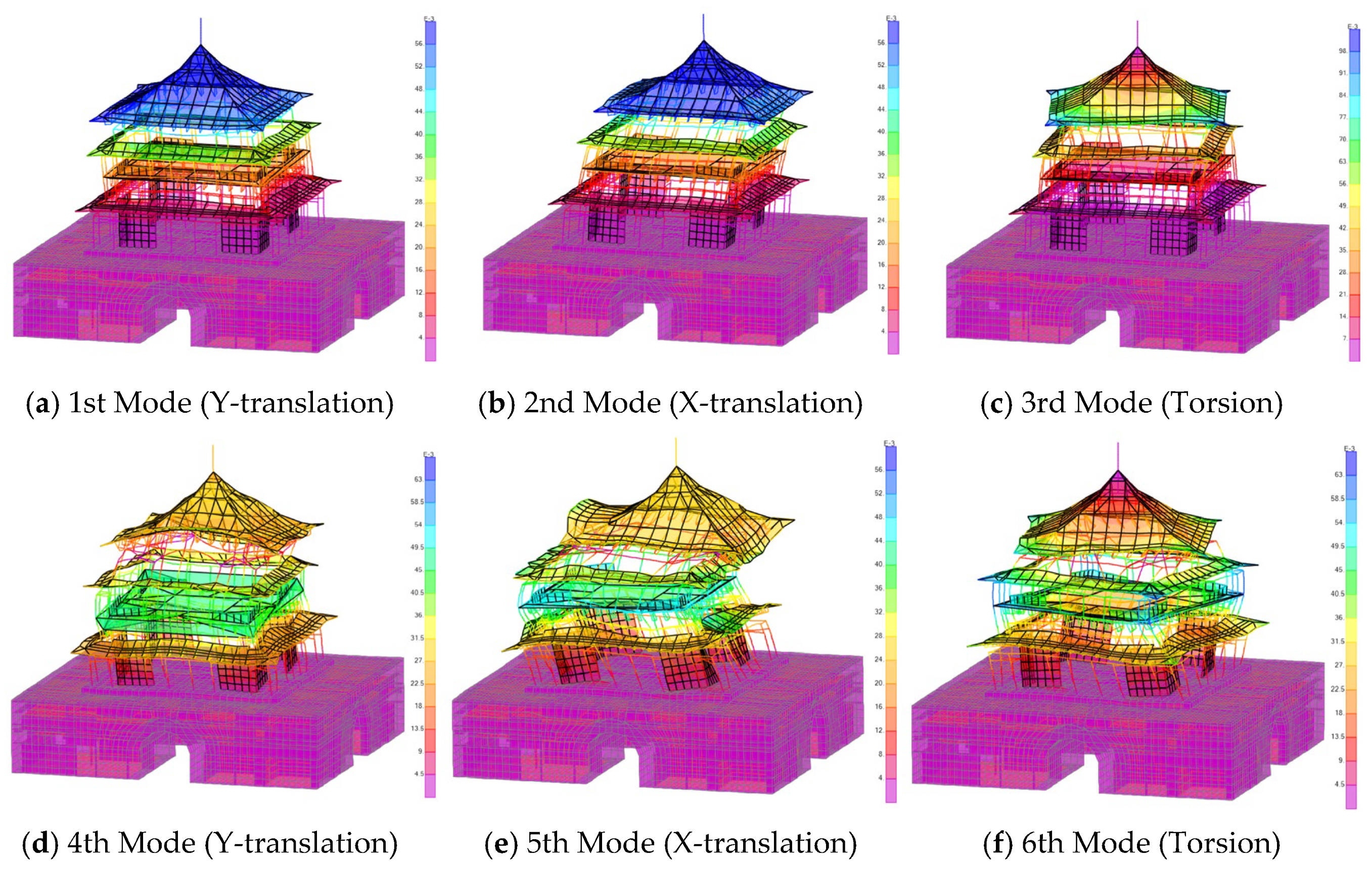
Modal analysis of the global structure was conducted using the eigenvector method. The representative gravity load, defined as Dead Load and half of the Live Load, was converted into structural mass for the calculation. The first six mode shapes of the global Xi’an Bell Tower model were extracted and are illustrated in Figure 8.
Figure 8.
Mode shapes of the global structural model.
Based on the first 60 modes, the cumulative mass participation ratios were obtained: 93.2% in the X-direction (North–South), 93.2% in the Y-direction (East–West), and 82% in the Z-direction. Detailed parameters regarding the initial modes are listed in Table 6.
Table 6.
Main structural periods.
The fundamental frequency of the overall structure is 1.46 Hz. Specifically, the first and second natural frequencies of the high-platform model are 5.3 Hz and 6.69 Hz, respectively; while those of the timber superstructure model are 1.60 Hz and 4.65 Hz, respectively.
When compared with the in situ frequency test results presented in Table 1 of Section 2, the relative errors range from 1.6% to 3.8%. In contrast, reference studies on similar ancient towers report a minimum discrepancy of 8.8% between experimental and finite element results [19]. Therefore, the error margins obtained in this study are considered well within the acceptable range.
Specifically, the 1st and 2nd modes correspond to translational modes along the Y-axis and X-axis, respectively. Due to the cruciform symmetric layout of the Bell Tower’s archways and the close proximity of the natural frequencies along the X and Y axes, it is evident that the distribution of mass and stiffness within the horizontal plane is highly symmetric and uniform. This dynamic symmetry is advantageous for preventing the emergence of directional weak links in the structure under multi-directional seismic excitation. The third mode exhibits pure torsional vibration around the vertical axis (Z-axis). The ratio of the first torsional period to the first translational period is calculated to be 0.75. This value is significantly lower than the limit of 0.9 recommended by seismic design codes, indicating that the structure possesses substantial torsional stiffness.
A comparison between the timber superstructure-only model and the global model reveals that the incorporation of the masonry platform results in a slight elongation of the natural periods. This suggests that the deformation of the high platform contributes to an increase in the global flexibility of the system.
5. Static Analysis Under Vertical Loads
5.1. Calculation and Analysis of Vertical Deformation
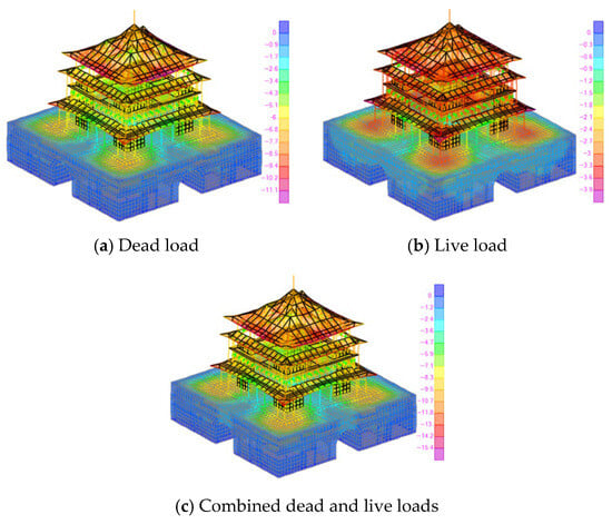
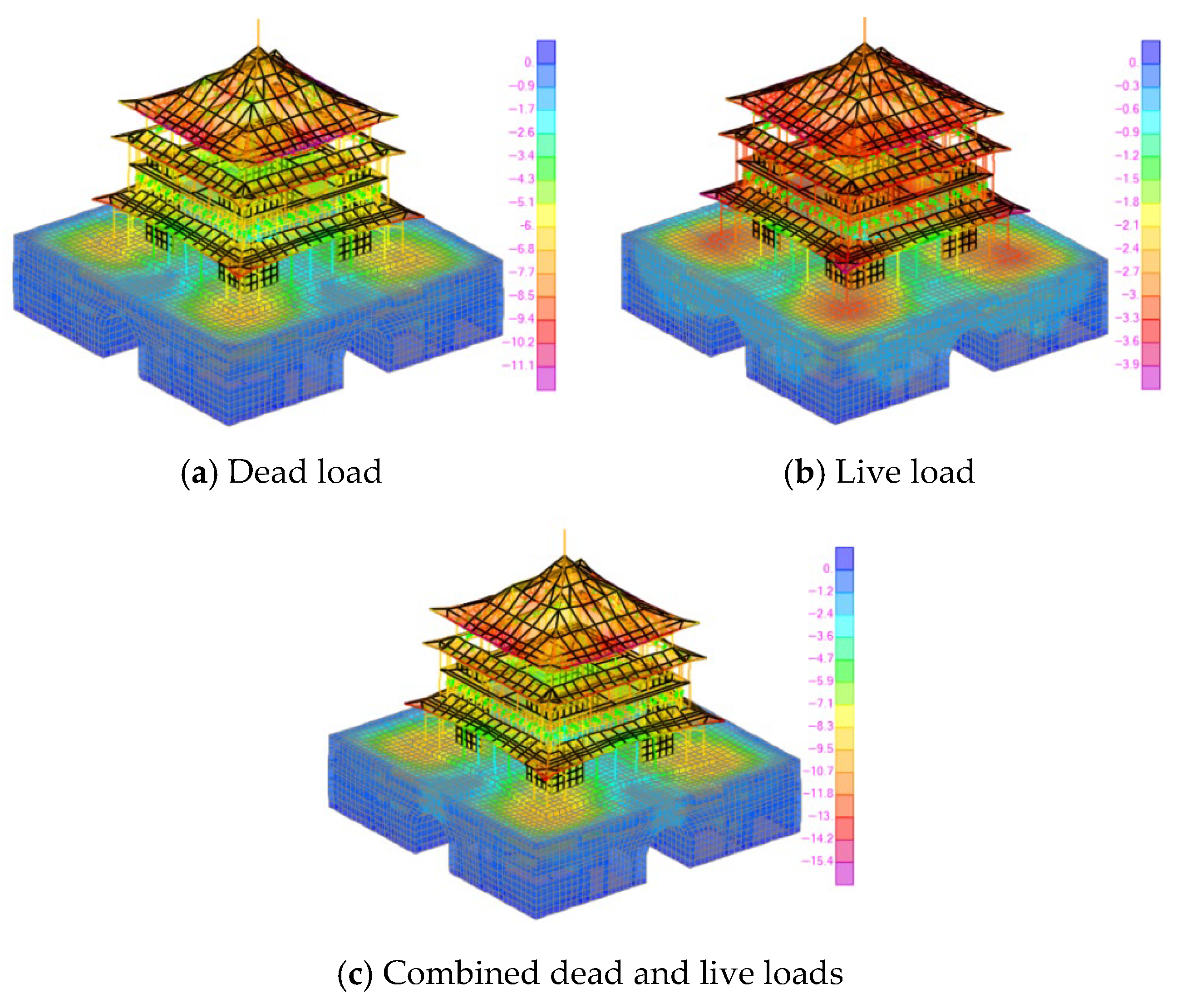
The static loads acting on the structure primarily consist of vertical loads under serviceability conditions, categorized into dead loads and live loads. To facilitate a comparative analysis, the structural deformations induced by dead loads and live loads were calculated separately. The calculation results regarding vertical deformations are illustrated in Figure 9.
Figure 9.
Calculation results of vertical deformation (Unit: mm).
Specifically, the dead load accounts for the self-weight of both structural and non-structural components. The self-weight of the roof system was taken as 4.096 kN/m2. For the timber floor slabs on the second story, a load of 2.0 kN/m2 was adopted to account for the weight of the slabs themselves, as well as superimposed loads such as partition walls and display cabinets. The structural deformation under the dead load is depicted in Figure 9a.
Regarding live loads, a value of 3.5 kN/m2 was applied to the floors of the first and second stories, in accordance with Item 4, Table 5.1.1 of the Load Code for the Design of Building Structures (GB 50009-2012) [26]. For the main roof and overhanging eaves, a snow load with a 100-year recurrence interval was initially set at 0.3 kN/m2 based on GB 50009-2012. This value was subsequently modified to 0.36 kN/m2 according to the Technical Standard for Maintenance and Strengthening of Ancient Timber Buildings (GB/T 50165-2020) [27]. The calculated deformation under live loads is shown in Figure 9b. Furthermore, the structural deformation under the load combination for the serviceability limit state (Sk = 1.0 × Dead Load + 1.0 × Live Load) was calculated and is illustrated in Figure 9c. The application of full-span dead and live loads across the entire floor area is intended to simulate the most unfavorable conditions for subsequent static and dynamic analyses, thereby explicitly revealing the failure characteristics of the structural components.
As observed in Figure 9, the global deformation of the Bell Tower under serviceability load conditions exhibits a symmetric and uniform pattern. Notably, the deformation induced by dead loads exceeds that caused by live loads. Due to the presence of the rammed earth core within the platform -which possesses a lower elastic modulus compared to the surrounding masonry -larger vertical deformations were observed at the corners of the superstructure under serviceability loads. The deformation values at representative locations within the Xi’an Bell Tower were extracted and are summarized in Table 7.
Table 7.
Structural deformation under serviceability conditions (Unit: mm).
As indicated in Table 7, the deformation values of all components under dead loads were significantly larger than those under live loads (approximately 2.0 to 2.5 times). This indicates that the structural self-weight is the dominant factor contributing to the vertical deformation of the Bell Tower under serviceability conditions. Notably, the vertical deformation at the column bases located on top of the platform reached −9.34 mm, accounting for more than 90% of the total displacement at the top of the structure. This suggests that the global vertical deformation of the Bell Tower primarily originates from the vertical compressive deformation of the platform induced by the timber superstructure. In contrast, the elastic compressive deformation of the timber superstructure itself is negligible, demonstrating the substantial vertical stiffness of the timber frame.
Furthermore, at the same elevation, the deformation of corner components was significantly greater than that of central components. Specifically, at the top of the platform, the vertical deformation at the corners (−9.34 mm) far exceeded that at the geometric center (−3.44 mm). This discrepancy highlights the relatively lower stiffness at the edges and corners of the platform, revealing distinct characteristics of non-uniform vertical deformation.
5.2. Stress Analysis
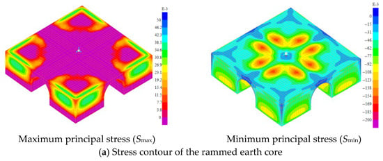
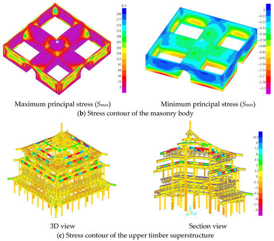
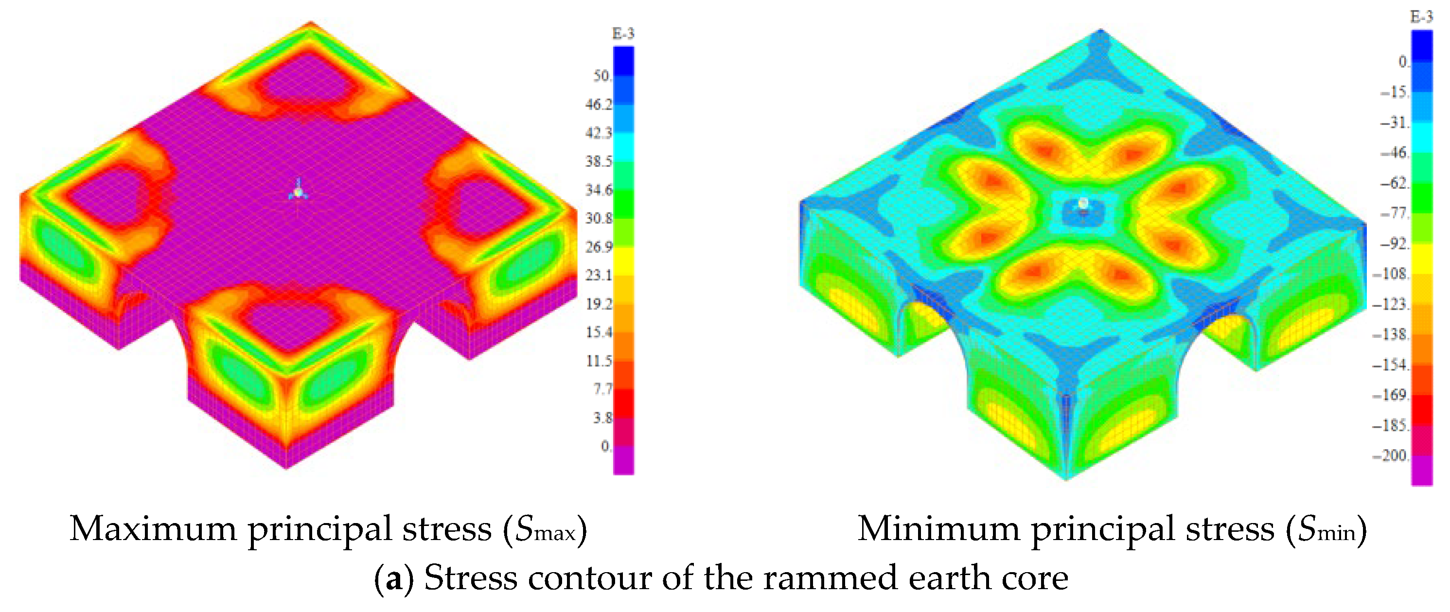
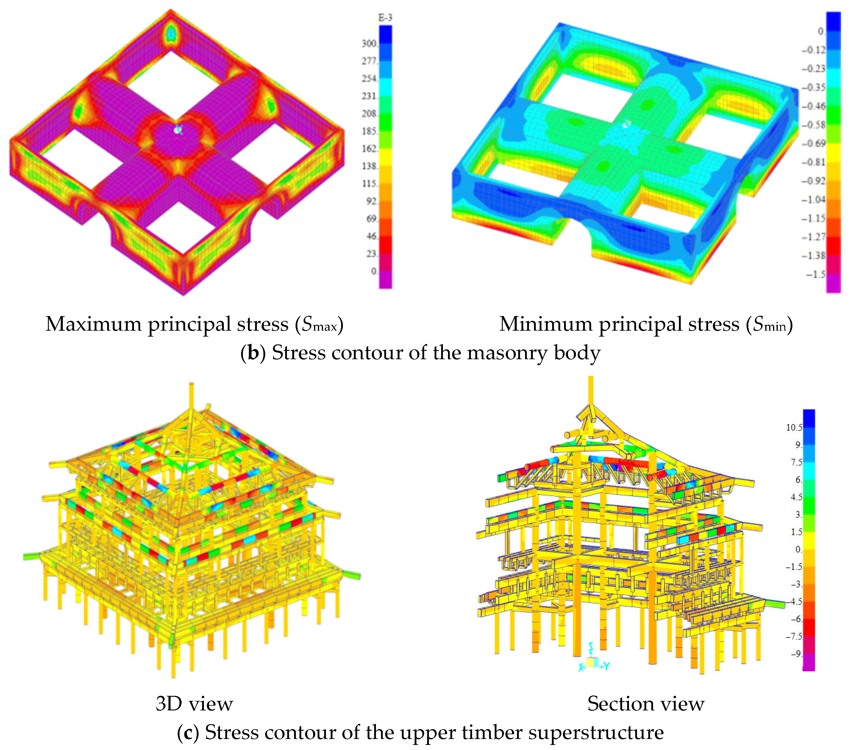
The stress distribution contours of the rammed earth core, the masonry body of the platform, and the upper timber superstructure under combined loading conditions are illustrated in Figure 10. As observed in Figure 10a, regarding the rammed earth core, the maximum principal stress (0.05 MPa) occurred at the sidewalls of the arched tunnel. Conversely, the minimum principal stress (−0.2 MPa) appeared at the bottom of the platform. Analysis of Figure 10b reveals that for the masonry component, the maximum principal stress was concentrated at the corner connections of the walls, peaking at 0.30 MPa. The minimum principal stress reached −1.5 MPa and was located at the bottom of the external walls. For the timber superstructure shown in Figure 10c, the maximum principal stress was identified at the bottom edges (soffits) of the beams and architraves, as well as in the tension zones of the mortise-tenon joints. Under combined loading, the peak tensile stress reached 10.5 MPa. The minimum principal stress was −9.0 MPa, occurring in the compression zones of the beams and architraves, and at the column bases.
Figure 10.
Stress analysis of the structural model under combined loads (Unit: MPa).
The results of the vertical deformation and stress analysis clearly indicate that the upper timber superstructure exerts an influence on the deformation of the high-platform itself. Furthermore, in practice, the stiffness characteristics of the internal rammed earth core directly result in non-uniform vertical stiffness across the overall structure. This induces significant settlement in the upper timber structure, which subsequently alters its dynamic response characteristics. This implies that retrofitting measures must address the interaction between the high-platform and the superstructure; enhancing the stiffness of the high-platform boundaries and monitoring differential settlement are therefore just as critical as repairing the timber frame itself.
6. Lateral Load Analysis
In the dynamic analysis of the Bell Tower structure, the primary environmental actions considered were wind loads and seismic excitations.
6.1. Wind Load Analysis
6.1.1. Determination and Application of Wind Loads
The reference wind pressure for the Xi’an region is taken as 0.35 kN/m2 for a 50-year return period and 0.40 kN/m2 for a 100-year return period. The terrain roughness was classified as Category B, and the shape coefficient was set to 1.40. Given that the height of the main roof exceeds 30 m, the wind vibration effects were accounted for in the calculation. Regarding the load application, wind loads for the platform section were applied to the top surface of the platform. For the timber superstructure, loads were applied to the outer eaves, timber floor slabs, and the roof system. For the pyramidal roof, the effective windward area was taken as 0.5 times the gross projected area. The specific application locations and the characteristic values of the wind loads are summarized in Table 8.
Table 8.
Application positions and standard values of wind loads.
6.1.2. Inter-Story Drift Analysis
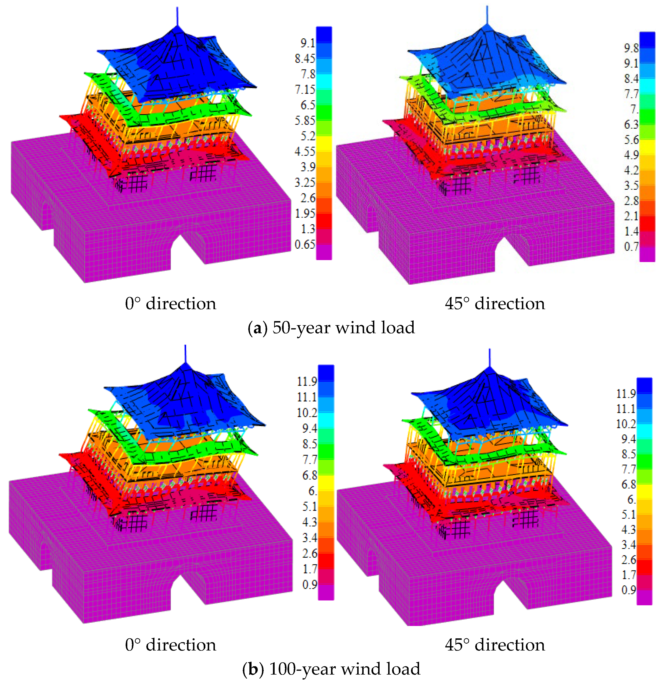
Given the symmetry of the Xi’an Bell Tower’s facade and geometric configuration in the X and Y directions, wind loads were applied at incidence angles of 0° and 45° relative to the X-axis. The structural deformations were calculated for both 50-year and 100-year return periods. The resulting displacement contours are presented in Figure 11.
Figure 11.
Structural deformation contour under wind loads (Unit: mm).
The horizontal displacements in the X-direction at critical locations were extracted under wind loads at 0° and 45° incidence angles. The inter-story drift ratios of the superstructure were calculated using the average displacement values of each floor. Specifically, the story height for the second story is defined from the second-story timber floor to the tops of the outer hypo style columns. The story height for the roof level extends from the tops of these columns to the pyramidal roof. The detailed inter-story drift ratios for each load case are listed in Table 9.
Table 9.
Inter-story drift ratio of the structure under wind loads (Unit: rad).
Analysis of the tabulated data reveals that the structural responses under 0° and 45° wind directions are substantially consistent. This further corroborates the uniform distribution of mass and lateral stiffness within the horizontal plane of the Bell Tower. A comparison of the response across different stories indicates that the inter-story drift ratio of the second story is significantly larger than that of the first story. Under the extreme wind load (100-year recurrence interval), the maximum drift ratio of the second story reaches 1/583, identifying it as the zone with the most significant deformation. This behavior is primarily attributed to the substantial stiffness of the first story, provided by the restraint of masonry infill walls and the column grid, whereas the second story exhibits relatively higher flexibility.
Even under the 100-year wind load, the maximum inter-story drift ratio remains far below the conventional allowable limit of 1/250 for timber structures. This demonstrates that the Xi’an Bell Tower possesses sufficient lateral stiffness. The structure remains within the elastic range under extreme wind loads, ensuring a high level of structural safety.
6.1.3. Stress Analysis
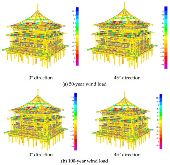
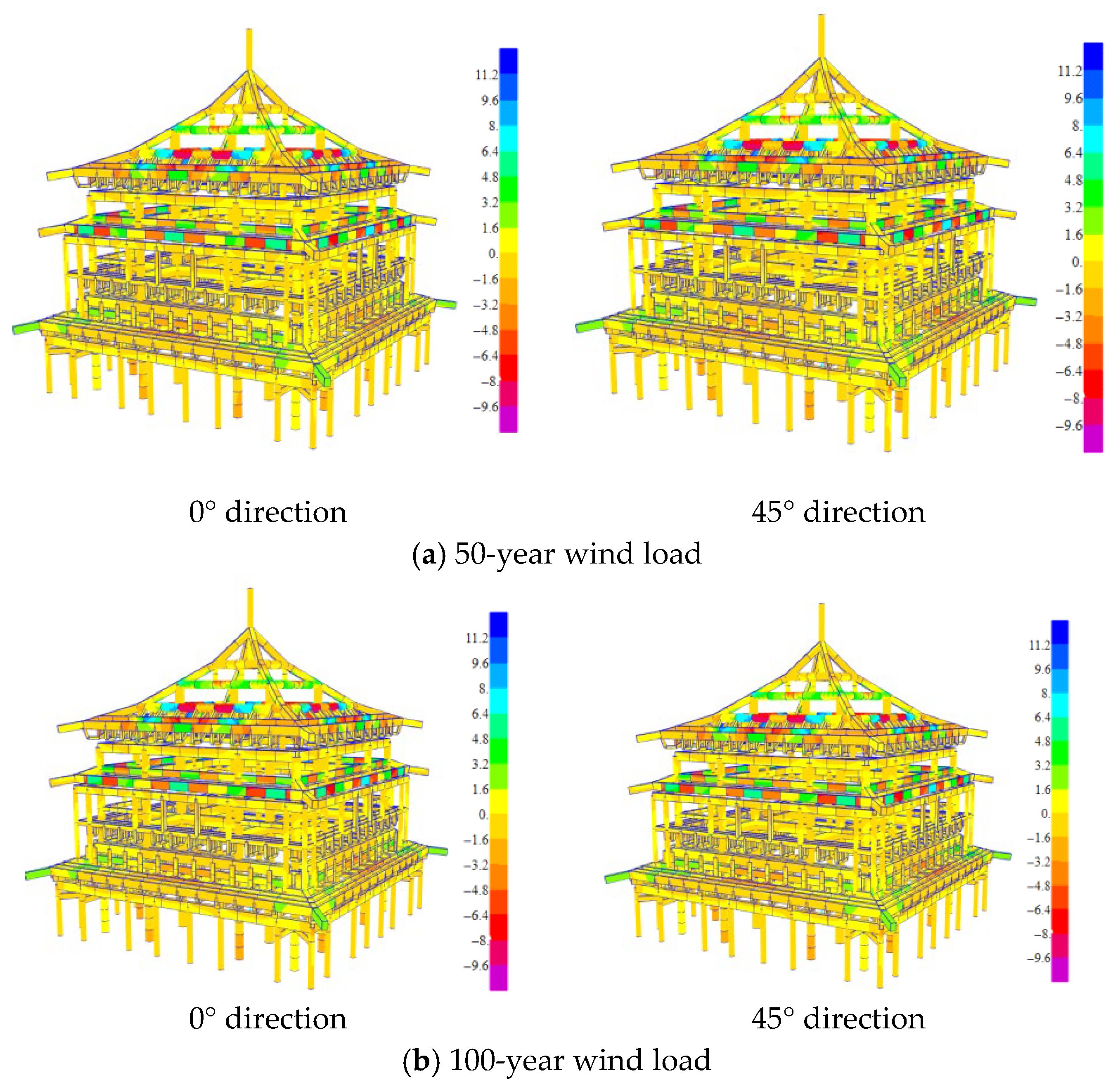
Given that the deformation of the platform under wind loads is negligible, this section focuses primarily on the stress analysis of the timber superstructure. The stress distributions within the structure were extracted based on the load combination: Dead Load + Live Load + wind load, as illustrated in Figure 12.
Figure 12.
Stress contour of the timber structure under combined wind loads.
As shown in Figure 12a, under the wind load with a 50-year return period, the maximum and minimum stresses in the timber superstructure are 11.17 MPa and −9.41 MPa, respectively. Conversely, under the wind load with a 100-year return period (Figure 12b), the maximum and minimum stresses increase to 11.61 MPa and −9.60 MPa, respectively. A comparison with the static analysis results (Section 5) indicates that wind loads have a limited influence on the stress state of the timber superstructure of the Xi’an Bell Tower.
6.2. Seismic Action Analysis
6.2.1. Selection of Seismic Action Parameters
According to the Seismic Ground Motion Parameters Zonation Map of China (GB 18306-2015) [28], the Xi’an Bell Tower is located in a region with a seismic fortification intensity 8. Consequently, seismic actions were evaluated at two levels: (1) Frequent earthquakes (Peak Ground Acceleration, PGA = 70 gal): The acceleration response spectrum was defined based on the criteria for frequent earthquakes in an 8-degree zone. The characteristic site period (Tg) was set to 0.40 s. The maximum seismic influence coefficients were 0.1776 g for the horizontal direction and 0.1154 g for the vertical direction. (2) Rare earthquakes (PGA = 400 gal): The response spectrum was defined for rare earthquakes in an 8-degree zone. The Tg was taken as 0.45 s. The maximum seismic influence coefficients were increased to 0.90 g (horizontal) and 0.585 g (vertical).
The seismic response was calculated using the mode-superposition response spectrum method. The first 60 vibration modes were combined, achieving cumulative mass participation ratios of 93.2% in the X-direction, 93.2% in the Y-direction, and 82% in the Z-direction. The damping ratios of the structural model were selected based on the shake table test data of the Xi’an Andingmen Gate Tower [25], which bears significant structural similarity to the Bell Tower. Specifically, the damping ratio was set to 3.5% under frequent earthquakes; under rare earthquakes, the structural damping is expected to increase and was therefore set to 5%.
6.2.2. Structural Deformation
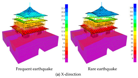
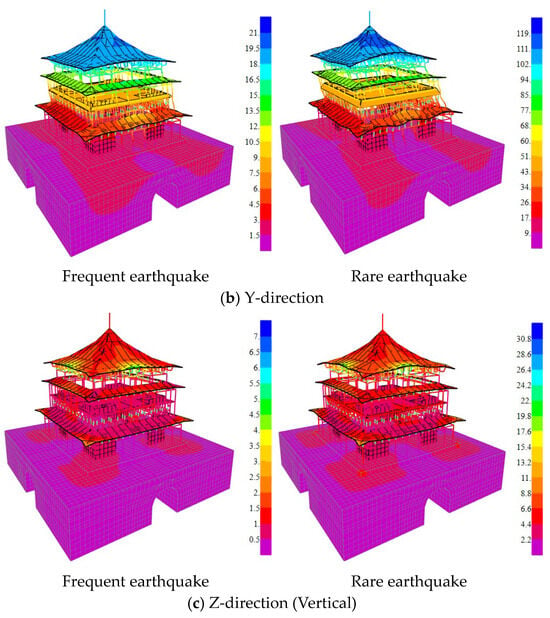
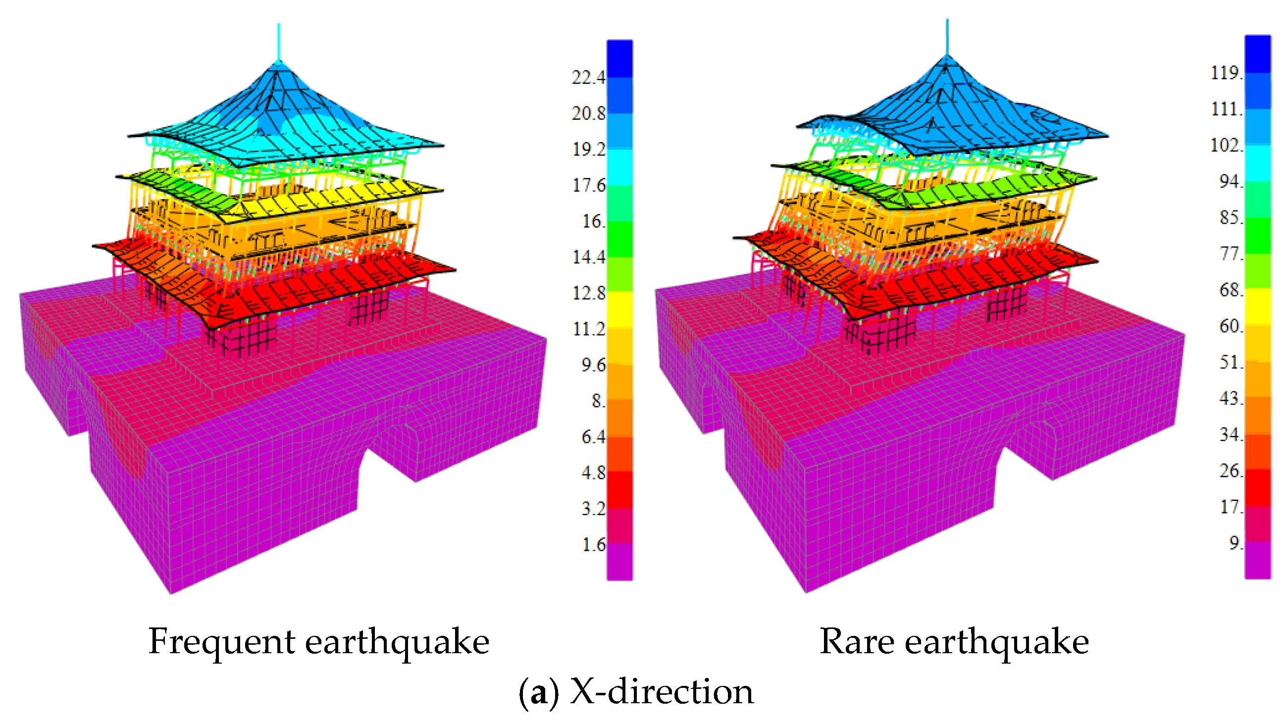
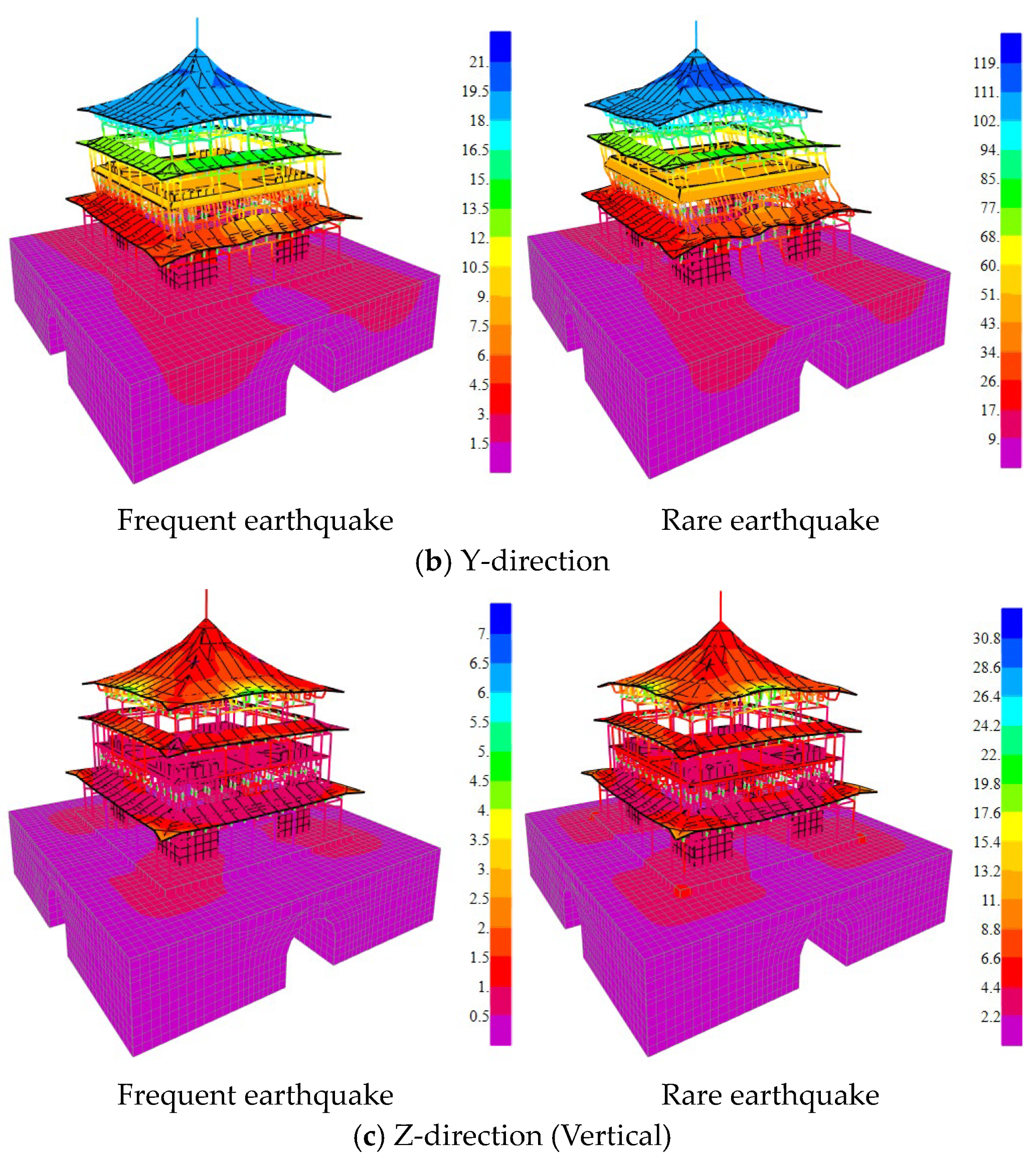
Based on the seismic response analysis, the structural deformations in the X, Y, and Z directions were obtained, as illustrated in Figure 13. It is observed that the horizontal displacement amplitudes under seismic actions in the X and Y directions are substantially consistent. The maximum displacement consistently occurs at the apex of the pyramidal roof. Specifically, under frequent earthquakes, the peak displacement at the apex is 19.16 mm, whereas under rare earthquakes, it reaches 108.98 mm.
Figure 13.
Structural deformation contour under seismic loads (Unit: mm).
Furthermore, as depicted in Figure 13c, the structural deformation under vertical seismic actions is relatively minor. The maximum vertical displacement is localized at the mid-span region of the main roof’s bottom eave. At the apex of the pyramidal roof, the vertical displacement is merely 1.09 mm under frequent earthquakes and 6.18 mm under rare earthquakes. The minimal vertical displacement indicates that the vertical seismic excitation has a limited impact on the overall response of the Xi’an Bell Tower.
The inter-story drift ratios of the superstructure were calculated based on the average displacement of each floor and are summarized in Table 10. It is observed that under both frequent and rare earthquake scenarios, the inter-story drift ratios of the platform are significantly smaller than those of the timber superstructure. This implies that the deformation of the Bell Tower is primarily concentrated within the upper timber superstructure. Specifically, under frequent earthquakes, the maximum inter-story drift ratio of the timber superstructure is 1/394, which satisfies the limit requirement of 1/250. Under rare earthquakes, the maximum drift ratio reaches 1/70, which remains well within the allowable limit of 1/30 for ancient timber structures. This demonstrates that the Xi’an Bell Tower possesses a sufficient margin of collapse resistance under major earthquakes, attributed to the superior flexibility and deformation capacity of the timber structure.
Table 10.
Inter-story drift ratio of the structure under seismic loads (Unit: rad).
6.2.3. Stress Results
- (1)
- Unidirectional Seismic Action
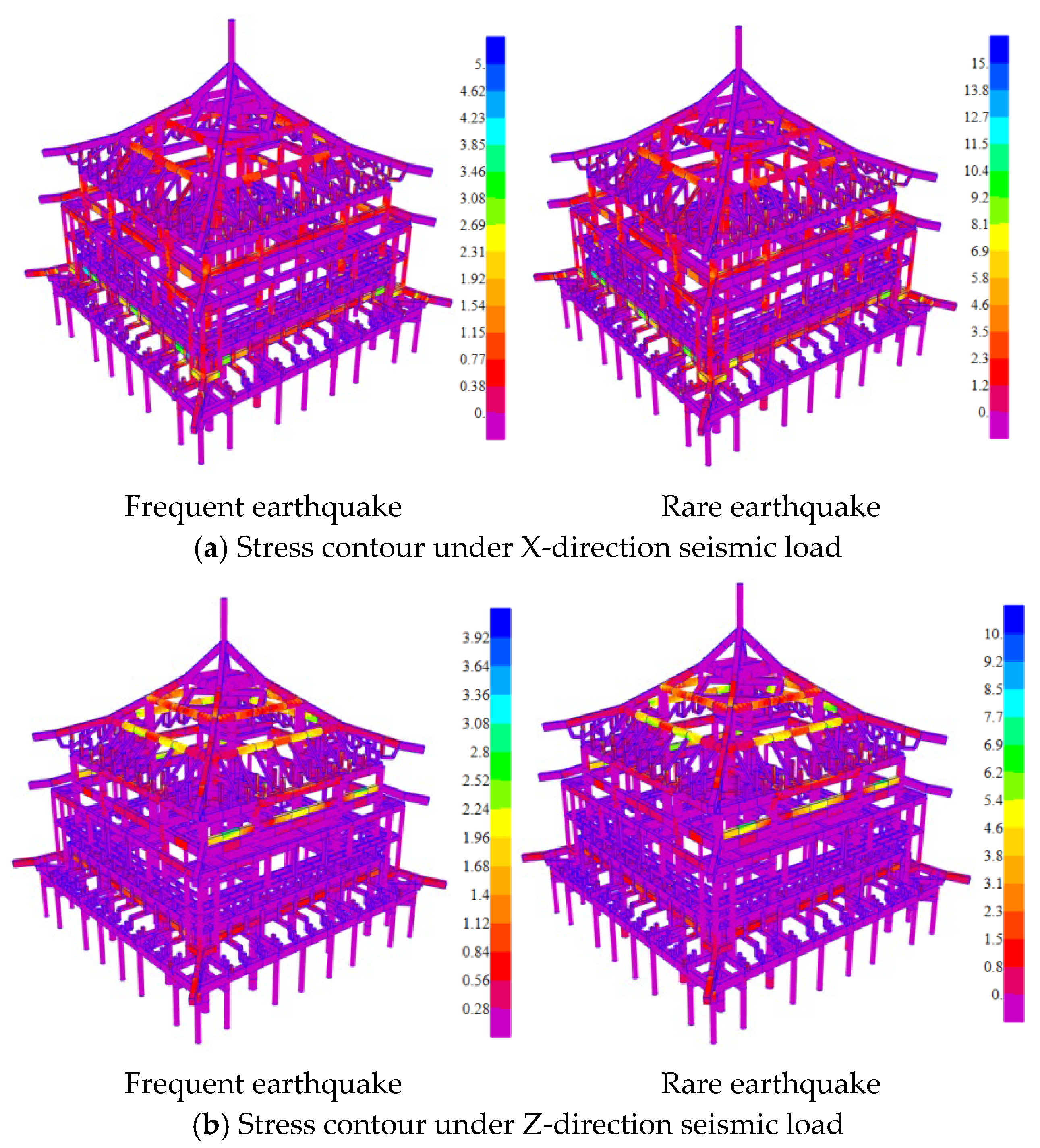
Given the structural symmetry of the Xi’an Bell Tower along the X and Y axes, the X-direction and Z-direction seismic excitations were selected as representative cases to investigate the structural response under horizontal and vertical earthquakes, respectively. The resulting stress distributions of the timber superstructure are illustrated in Figure 14.
Figure 14.
Stress contour of the structure under unidirectional seismic loads (Unit: MPa).
As observed in Figure 14a, the horizontal seismic action primarily affects the beams on the first story. Under frequent earthquakes, the maximum stress in the timber superstructure is 4.85 MPa. Under rare earthquakes, the maximum stress increases to 14.35 MPa.
Conversely, as indicated in Figure 14b, the vertical seismic action exerts a significant influence on the beams of the main roof. The maximum stress in the timber superstructure reaches 3.92 MPa under frequent earthquakes and 9.60 MPa under rare earthquakes.
- (2)
- Combined Seismic Action
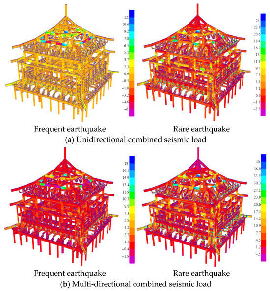
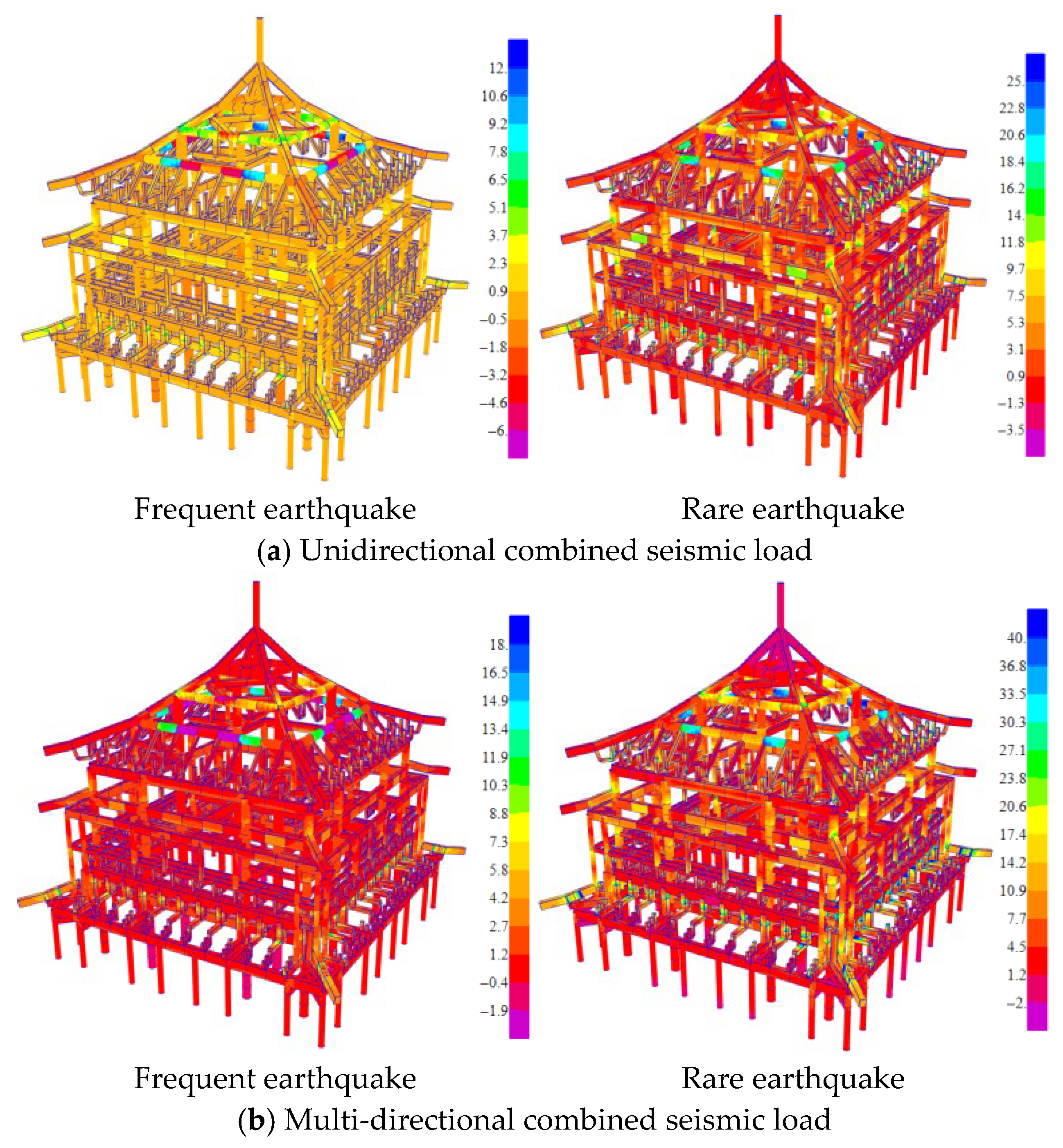
Seismic load combinations were categorized into two cases: unidirectional horizontal seismic combination and multi-directional seismic combination. Unidirectional combination: This case considers the representative gravity load combined with the unidirectional horizontal seismic action (Dead Load + 0.5 × Live Load + X-direction Seismic Effect). The corresponding stress distribution contours are presented in Figure 15a. Under frequent earthquakes, the maximum stress within the timber superstructure is 12 MPa. Under rare earthquakes, the maximum stress in vertical components reaches 18.5 MPa, localized at the beam-column joints. The global maximum stress of the timber structure peaks at 25 MPa, with high-stress zones concentrated in the roof system.
Figure 15.
Stress contour of the structure under combined seismic loads (Unit: MPa).
Multi-directional combination: This case accounts for the coupling of the representative gravity load and multi-directional seismic actions (Dead Load + 0.5 × Live Load + Combined Seismic Effect). The combined seismic action is defined as X-EQ + 0.85 × Y-EQ + 0.65 × Z-EQ. The resulting stress contours are shown in Figure 15b.
As observed in the figures, high-stress concentration zones are located at the mortise-tenon joints of beam-column intersections, the ends of architraves, and the Dou-Gong layer. In contrast, the columns generally exhibit a low-stress state. This indicates that under multi-directional coupled seismic actions, the joints serve as core regions for internal force redistribution and energy dissipation. Subjected to significant bending moments and shear forces, these joints constitute the weak links in the structure’s seismic resistance. Furthermore, under rare earthquake conditions, the maximum structural stress increases to 40 MPa, which exceeds the tensile limit of the timber parallel to the grain. This demonstrates that as seismic intensity increases, the joints of this timber structure face a distinct risk of splitting failure and plastic damage.
7. Conclusions
In this study, the Xi’an Bell Tower was selected as the case study. A three-dimensional finite element model comprising the internal rammed earth core, the masonry body, and the upper timber superstructure was established to investigate the structural responses of this high-platform timber structure system under various loading conditions. The main conclusions are drawn as follows:
- The simulated first two natural frequencies of the platform and the timber superstructure correlate well with the in situ dynamic testing results, validating the accuracy of the FE model. The structure exhibits symmetric dynamic characteristics, and the ratio of the first torsional period to the first translational period is 0.75, indicating substantial torsional stiffness. Furthermore, the incorporation of the platform into the model significantly prolongs the natural periods of the global structure compared to the timber superstructure alone.
- Dead loads are the dominant factor governing the structural vertical deformation. The deformation at the top of the platform exhibits a non-uniform distribution pattern characterized by “larger deformations at the corners and smaller deformations at the center,” with the vertical displacement at the corners being approximately 2.7 times that at the geometric center. This phenomenon results from the deformation of the underlying platform under the load of the timber superstructure, suggesting that special attention should be paid to the settlement at the edges of the platform in the conservation of ancient architecture.
- Under lateral actions induced by wind and seismic loads, structural deformations are primarily concentrated in the second story of the timber superstructure, identifying it as a zone with relatively weak lateral stiffness. The maximum inter-story drift ratio reaches 1/583 under the wind load with a 100-year return period, whereas it increases to 1/70 under rare earthquakes. This indicates that the structure is significantly more sensitive to seismic excitations than to wind loads.
- Under multi-directional seismic actions, high-stress zones are primarily concentrated at the mortise-tenon joints within beam-column intersections and the Dou-Gong (bracket set) layer at the ends of the architraves. In particular, the local maximum stress at the joints can reach 40 MPa, exceeding the elastic limit of the timber. This indicates a significant risk of splitting failure and plastic damage. Consequently, these areas constitute the weak links in the structure’s seismic resistance, necessitating prioritized protection and preventive measures for these high-stress regions.
Author Contributions
P.W.: Conceptualization, Writing and Software. Y.D.: Supervision, Conceptualization, Writing—review and editing. All authors have read and agreed to the published version of the manuscript.
Funding
This research received no external funding.
Data Availability Statement
The original contributions presented in this study are included in the article. Further inquiries can be directed to the corresponding author.
Conflicts of Interest
The authors declare no conflict of interest.
References
- Shen, F. Architecture in Ming and Qing Dynasties (Section 2). In A History of Chinese Architecture; Palgrave Macmillan: Singapore, 2025; pp. 179–222. [Google Scholar]
- Wang, X.; Hu, W.B.; Meng, Z.B. Damage alarming analysis for ancient wood structures based on wavelet packet energy spectrum. Multidiscip. Model. Mater. Struct. 2014, 10, 593–610. [Google Scholar] [CrossRef] [Scilit]
- Li, S.; Zhou, Z.; Luo, H.; Milani, G.; Abruzzese, D. Behavior of traditional Chinese mortise-tenon joints: Experimental and numerical insight for coupled vertical and reversed cyclic horizontal loads. J. Build. Eng. 2020, 30, 101257. [Google Scholar] [CrossRef] [Scilit]
- Zhang, X.; Cui, L.; Qi, H.; Wang, H.; Lin, L. Seismic fragility analysis of traditional Chinese timber structures based on a simplified lumped mass model considering joint damage. Structures 2024, 70, 107863. [Google Scholar] [CrossRef] [Scilit]
- He, J.; Yu, P.; Wang, J.; Yang, Q.; Han, M.; Xie, L. Theoretical model of bending moment for the penetrated mortise-tenon joint involving gaps in traditional timber structure. J. Build. Eng. 2021, 42, 103102. [Google Scholar] [CrossRef] [Scilit]
- Zhou, Q.; Yan, W. Aseismic behaviors of ancient Chinese structures strengthened by different methods. Stud. Conserv. 2014, 60, 384–392. [Google Scholar] [CrossRef] [Scilit]
- Shabani, A.; Kioumarsi, M.; Plevris, V.; Stamatopoulos, H. Structural Vulnerability Assessment of Heritage Timber Buildings: A Methodological Proposal. Forests 2020, 11, 881. [Google Scholar] [CrossRef] [Scilit]
- Chen, M.; Wu, Z.; Dong, J. Dynamic Performance and Seismic Response Analysis of Ming Dynasty Masonry Pagodas in the Jiangnan Region: A Case Study of the Great Wenfeng Pagoda. Buildings 2025, 15, 3994. [Google Scholar] [CrossRef] [Scilit]
- Wu, C.; Xue, J.; Song, D. Hysteretic behaviors reinforcement of Dou-Gong brackets: Experimental and numerical study. Structures 2022, 46, 299–321. [Google Scholar] [CrossRef] [Scilit]
- Song, D.; Xue, J.; Wu, C. Experimental and numerical analysis on seismic behavior of corner Dou-Gong bracket in ancient timber buildings. Soil Dyn. Earthq. Eng. 2024, 182, 108749. [Google Scholar] [CrossRef] [Scilit]
- Yang, R.; Mapesela, S.; Li, H.; Lorenzo, R. Mechanical properties of Dougong bracket in Chinese traditional timber structure under vertical loads: A systematic review. J. Build. Eng. 2023, 68, 106125. [Google Scholar] [CrossRef] [Scilit]
- Liu, K.; Liao, H.; Xue, B.; Wu, C.; Xue, J.; Song, D.; Xue, H. Analysis of Dynamic Characteristics and Seismic Response of Chen Xiang Pavilion in Xi’an Considering the Lower Stylobate. Buildings 2024, 14, 3742. [Google Scholar] [CrossRef] [Scilit]
- Chen, S.; Wang, S.; Li, C.; Hu, Q.; Yang, H. A Seismic Capacity Evaluation Approach for Architectural Heritage Using Finite Element Analysis of Three-Dimensional Model: A Case Study of the Limestone Hall in the Ming Dynasty. Remote Sens. 2018, 10, 963. [Google Scholar]
- Lu, J.; Han, X.; Wang, Z.; Li, C. Research on Dynamic Properties of Ancient Masonry Pagoda with Solid Structure in China. Int. J. Archit. Herit. 2020, 16, 746–766. [Google Scholar]
- Zhou, J.; Hu, J.; Zhang, B.; Sun, M.; Wang, S. Dynamic Characteristics Analysis and Finite Element Simulation of an Ancient Timber Building under Environmental Excitation. Buildings 2024, 14, 771. [Google Scholar] [CrossRef] [Scilit]
- Ayala, D.F.D.; Tsai, P.H. Seismic vulnerability of historic Dieh–Dou timber structures in Taiwan. Eng. Struct. 2008, 30, 2101–2113. [Google Scholar] [CrossRef] [Scilit]
- Ishibashi, S.; Hayashi, K. Effects of Ground Displacement on the Ultimate Response of Soil–Pile–Superstructure Interaction Systems under Huge Earthquakes. Struct. Eng. Int. 2025, 1–6. [Google Scholar] [CrossRef] [Scilit]
- Hong, N.; Ling, Y.; Yang, Z.; Ha, X.; Xu, B. Shaking Table Test of a Subway Station–Soil–Aboveground Structures Interaction System: Structural Impact on the Field. Buildings 2025, 15, 2223. [Google Scholar]
- Xue, H.; Xue, J.; Song, D.; Li, M.; Xue, B.; Wu, C.; Sui, Y. Dynamic Characteristics and Seismic Response of Multi-Story Wooden Tower Considering the Influence of a High Stylobate. Buildings 2025, 15, 269. [Google Scholar] [CrossRef] [Scilit]
- Zhang, X.; Ma, H.; Zhao, Y.; Zhao, H. Dynamic responses on traditional Chinese timber multi-story building with high platform base under earthquake excitations. Earthq Struct. 2020, 19, 331–345. [Google Scholar] [CrossRef]
- Han, Y.; Chun, Q.; Xu, X.; Teng, Q.; Dong, Y.; Lin, Y. Wind effects on Chinese traditional timber buildings in complex terrain: The case of Baoguo Temple. J. Build. Eng. 2022, 59, 105088. [Google Scholar] [CrossRef] [Scilit]
- Han, Y.; Chun, Q.; Jin, H. Wind-induced vibration performance of early Chinese hall-style timber buildings. J. Wood Sci. 2021, 67, 4. [Google Scholar]
- Zhao, J.; Yang, S.; Yu, M.; Sun, J. Elastoplastic Analysis for the Wall of the East Gate in Xi’an City by Finite Element Method. J. Northwest. Inst. Archit. Eng. 1998, 15, 1–7. [Google Scholar]
- Yu, M.; Liu, X.; Fang, D.; Zhang, X. An Experimental Study of Static and Dynamic Characteristics on the Front Tower Over the Ancient Xi’an City Wall. J. Xi’an Jiaotong Univ. 1991, 25, 55–62. [Google Scholar]
- Xue, J.; Wu, C.; Zhou, S.; Zhang, F. Analysis on dynamic characteristics and seismic response of the Anding Gate Tower in Xi’an considering high stylobate. J. Build. Struct. 2021, 42, 12–21. [Google Scholar] [CrossRef]
- GB 50009-2012; Load Code for the Design of Building Structures. China Architecture & Building Press: Beijing, China, 2012.
- GB/T 50165-2020; Technical Standard for Maintenance and Reinforcement of Ancient Timber Buildings. China Architecture & Building Press: Beijing, China, 2020.
- GB 18306-2015; Seismic Ground Motion Parameter Zonation Map of China. China Standards Press: Beijing, China, 2015.

Disclaimer/Publisher’s Note: The statements, opinions and data contained in all publications are solely those of the individual author(s) and contributor(s) and not of MDPI and/or the editor(s). MDPI and/or the editor(s) disclaim responsibility for any injury to people or property resulting from any ideas, methods, instructions or products referred to in the content. |
© 2026 by the authors. Licensee MDPI, Basel, Switzerland. This article is an open access article distributed under the terms and conditions of the Creative Commons Attribution (CC BY) license.