


Abstract
The shear design of concrete members reinforced with Carbon Fiber Reinforced Polymer (CFRP) bars remains a key hurdle for engineers. This study experimentally investigates the shear behavior of normal-strength concrete members reinforced with CFRP bars without shear reinforcement subjected to monotonic loading. Specifically, this research investigates the effect of anchorage length on shear-dominated behavior, aiming to provide a novel assessment of the interaction between shear and anchorage design—two aspects that have traditionally been treated in isolation in existing studies. The experimental results revealed that all test members, regardless of reinforcement type or anchorage length, exhibited a shear strength ranging from 1.1 to 5.63 times the code-predicted values, confirming the conservatism of current design standards. This pronounced difference in the shear strength of reinforced members is attributed to (1) the unexpectedly significant contribution of dowel action because of the high tensile strength and over-reinforcement ratio, and (2) the inherent conservatism in current code equations for shear capacity. Unlike prior studies that noted conservative shear prediction, this research demonstrated that anchorage length requirements, which are typically linked to flexural design, can be significantly relaxed in shear-dominated members with safety secured. This research highlights the need to refine shear prediction models for CFRP members by incorporating parameters that account for the reinforcement ratio and the unique contribution of dowel action. Furthermore, a revision of anchorage length design standards is justified to develop a more rational and economical design for shear-dominated members.
1. Introduction
Fiber-reinforced polymers (FRP) have emerged as a promising alternative for reinforcement in civil engineering over recent decades because of their exceptional mechanical properties and resistance to corrosion, making them ideal for both new construction and the strengthening of existing structures [1]. For instance, significant progress has been made not only in research on the behavior of concrete members reinforced with carbon fiber-reinforced polymer (CFRP) bars but also in applications involving slabs, tunnel concrete linings, and precast girder connections [2]. However, the shear design of these members remains a critical issue. As shear strength prediction models for CFRP members have been proposed by modifying those for RC members, the existing design standards tend to adopt a conservative approach when evaluating the shear strength of CFRP members based on RC models. Consequently, shear strength calculations based on ACI 440-03 and 06, CSA-S806-2, and CSA-S6-14 have also been reported to conservatively estimate the shear strength of CFRP members without stirrups [3,4,5].
This conservatism stems from uncertainties in how CFRP’s material properties affect established shear transfer mechanisms, particularly in members designed without shear reinforcement. According to the design standards for concrete structures, if it is confirmed that the bending moment and shear force can be adequately resisted without shear reinforcement, then the minimum shear reinforcement is not required for elements such as slabs and foundations. Additionally, deep beams (a/d ≤ 2.5) can transfer greater shear forces compared with slender beams, and are therefore used as transfer girders in buildings, cap beams in bridge bents, pile caps in foundations, and other heavily loaded structural members [5]. In previous studies, most shear strength prediction models applied to members without stirrups, regardless of the RC member type, tended to provide conservative estimates because of the uncertainty associated with shear failure [6,7].
The shear resistance of concrete without stirrups (Vc) comprises three components:
- (1)
- Resistance from uncracked concrete, which is closely related to the compressive and tensile strength (approx. 20–40% of the total shear resistance).
- (2)
- Resistance from aggregate interlocking, influenced by particle size and grading (approx. 33–50% of the total shear resistance).
- (3)
- Resistance from dowel action, which is further enhanced by the thickness of the concrete cover and presence of stirrups (approx. 15–25% of the total shear resistance).
While the shear transfer mechanism of CFRP members is similar to that of RC members, their material properties introduce critical differences. For instance, the relatively low elastic modulus of CFRP typically leads to wider and deeper cracks, which can reduce shear resistance by diminishing aggregate interlock [8]. Furthermore, the contribution of dowel action in CFRP members is frequently debated. Some studies suggest that the shear resistance transferred through dowel action tends to decrease owing to differences in the material properties compared with rebars [9]. Conversely, other research indicates that, under certain conditions—such as high reinforcement ratios or specific layout configurations—dowel action can contribute significantly to shear resistance [10,11]. Specifically, when a large amount of longitudinal reinforcement is present, especially in multiple layers throughout the tension zone, dowel action can account for a substantial portion [10,12]. This creates a seemingly contradictory behavior where the linear–elastic nature and high tensile strength of CFRP might actually enhance the shear resistance in ways not fully captured by the current models.
This uncertainty is compounded by regulations for anchorage length, particularly in members governed by a shear failure mode. All design standards recommend securing an anchorage length sufficient to prevent anchorage failure before the reinforcement yields. However, the regulations for cases where shear failure precedes flexural failure remain ambiguous. Determining the anchorage length based solely on flexural design raises concerns regarding excessive member size or over-reinforcement, issues that are particularly critical for CFRP members. While the existing studies have reported on the conservatism of shear strength predictions for FRP reinforcement and the significance of dowel action, there remains a scarcity of research exploring the influence of anchorage length on shear behavior. By evaluating these two factors—shear capacity and anchorage—in conjunction, this study offers a novel perspective on the potential for unnecessarily conservative anchorage length requirements in shear-dominated members. Furthermore, this research makes both academic and practical contributions by proposing improved design methodologies specific to CFRP-reinforced members.
To investigate the potential overdesign stemming from these interconnected issues, this study was conducted. Shear failure is induced in over-reinforced test members, with the flexural reinforcement type and anchorage length as the experimental variables. This research was conducted with the following objectives:
- (1)
- To compare the experimental test results with shear design calculations to verify the actual shear strength of the members.
- (2)
- To examine how the provided anchorage length (shorter than code requirements) performs in shear-dominated members, and whether current anchorage length equations are overly conservative in such cases.
- (3)
- To provide fundamental data for the development of a more accurate analytical model that overcomes the limitations of current conservative approaches.
2. Materials and Methods
2.1. Materials
2.1.1. Reinforcement
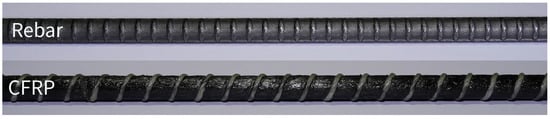
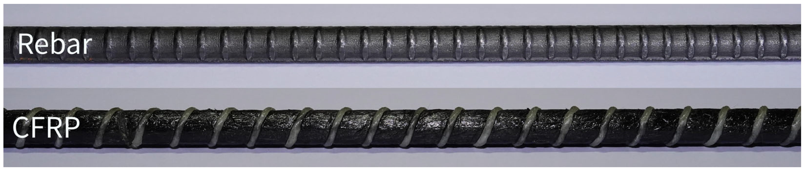
The main reinforcements used in this study are Carbon Fiber Reinforcement Polymer (CFRP) and rebar. Steel-reinforced concrete members (hereinafter referred to as RC members) were used as comparative members to compare with CFRP-reinforced members (hereinafter referred to as CFRP members). CFRP bars with thread-wrapped surfaces were used (Figure 1), as this deformation pattern provided a better mechanical interlock and bond performance than smooth bars. Such high bond strength can delay crack initiation, indicating an enhanced energy dissipation capacity [13].
Figure 1.
Reinforcements used in members.
The mechanical properties of the main reinforcement used in this study are shown in Table 1. The tensile strength of CFRP bars was prepared according to ASTM D 7205 [14], and their tensile strengths were measured when all the members were made. The tensile strength of rebar was evaluated according to ASTM E8/E8M-24 [15]. Regardless of the type of flexural reinforcement, stirrups were not placed in any of the members.
Table 1.
Mechanical properties of CFRP and steel reinforcement.
2.1.2. Concrete
The concrete used in this study was a ready-mixed product from a concrete plant. The air content was 4.5%, and the target slump was 150 mm. Both the members and cylindrical specimens (Ø100 × 200 mm) underwent air curing under the same conditions to achieve a consistent level of strength. The cylindrical specimens of compressive strengths were measured when all the member experiments were completed [16]. Additionally, each compressive strength value was the average of three specimens. At this point, to evaluate the elastic modulus of concrete specimens according to ASTM C469/C469M, a Linear variable differential transformer (LVDT) was installed, and the elastic modulus was calculated [17]. The measured compressive strength and modulus of elasticity were 31.7 MPa (standard deviation (SD) of 1.52 MPa) and 27.8 GPa (SD = 0.2 GPa), respectively. The concrete mix design used in this study is shown in Table 2.
Table 2.
Mix proportions.
2.2. Test Variables
This study designed an experiment to investigate the effect of anchorage length on the shear-dominated behavior of over-reinforced members without stirrups. The primary variables were the reinforcement type and the anchorage length, noting that a variation in anchorage length resulted in a corresponding change to the a/d. In this study, six simply supported members were constructed with a cross-section of 150 (b) × 200 (h) mm, having an effective depth (d) of 147.5 mm. Four members were reinforced with CFRP bars (denoted C-series) and two with conventional steel rebars (denoted S-series), as summarized in Table 3. The primary variables were (1) the type of flexural reinforcement (CFRP vs. rebar) and (2) the anchorage length of the reinforcement beyond the support (either 600 mm or 750 mm). In this paper, ‘Provided anchorage length’ refers to the length of the straight bar embedded in the end of the members (except for the 150 mm extension for LVDT installation), while ‘Required anchorage length’ denotes the theoretical length required by design codes. Meanwhile, Vc represents the shear strength of concrete without shear reinforcement (concrete contribution), and Vu denotes the ultimate shear strength of the member (shear capacity at failure).
Table 3.
Test variables for the beams.
For the 600 mm anchorage case, the total member length (end-to-end) was 1200 mm, whereas for the 750 mm anchorage it was 1500 mm. All members contained six 10 mm diameter tensile reinforcement bars (reinforcement ratio: 1.93%), regardless of reinforcement type. All members had no stirrups to enforce a shear failure mode. These variables are summarized in Table 3. It should be noted that the variation in anchorage length inherently altered the clear span and, consequently, the a/d. Specifically, members with a 600 mm anchorage length had a shear span of approximately 400 mm (a/d of 2.7), whereas those with a 750 mm anchorage length had a longer span of approximately 550 mm (a/d of 3.7). The rationale for selecting 600 mm and 750 mm was twofold: 600 mm corresponds to 60 times the bar diameter (60db), representing a short and potential unconservative anchorage length, while 750 mm is closer to code requirements. Thus, by comparing these two cases, the effect of a reduced anchorage length on shear performance can be evaluated.
2.3. Test Setup and Loading Procedure
CFRP bars cannot be bent into hooks and have unique bond characteristics. Therefore, CFRP bars were straightly extended to the outside by 150 mm. The support region—the distance from the support to the member’s end—was set equal to the members’ depth (200 mm) to accommodate the needed anchorage length. To check for any potential slip in all specimens, the displacement at both ends of the exposed CFRP bars was monitored.
A strain gauge was installed at the center of the reinforcement to measure the strain under the load. Considering the neutral axis depth, the concrete strain gauge was attached 20 and 40 mm from the edge of the compression zone for all members.
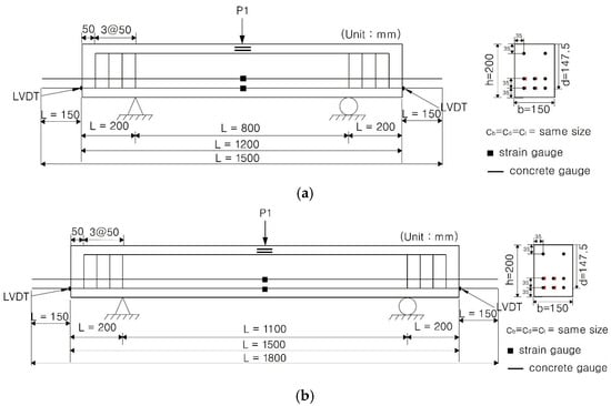
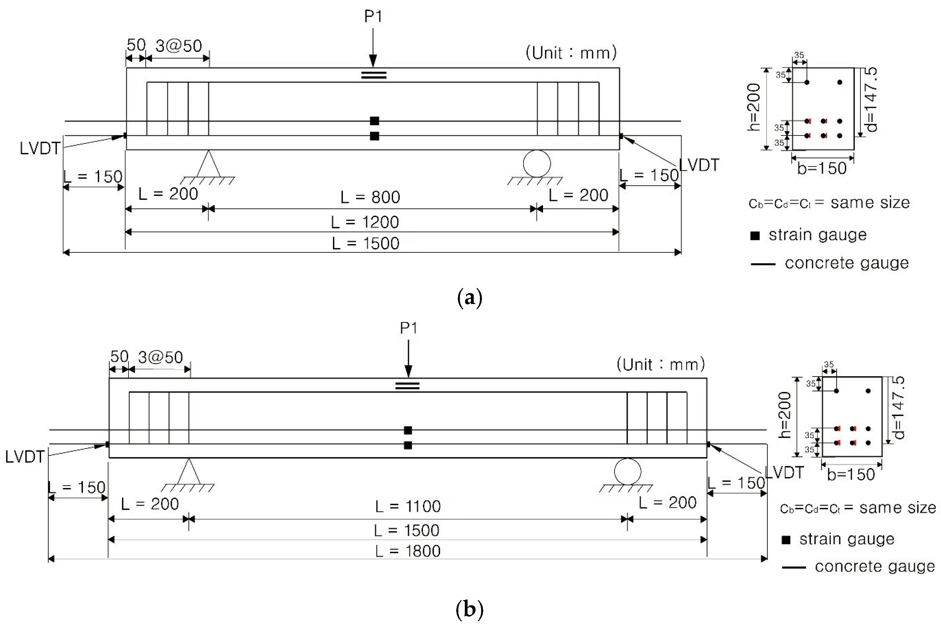
A three-point deflection-controlled loading method, as shown in Figure 2, was applied in this study. Moreover, the load on the members was applied using a monotonic loading method at a rate of 0.2 mm/min. Vertical loads were applied using a hydraulic servo-actuator with a capacity of 500 kN. To obtain vertical displacement with increasing load, two LVDTs were installed vertically at the bottom of the center section. Throughout the experiments, horizontal LVDTs were installed and placed in direct contact with the ends of the CFRP bar to measure slippage. After the experiment, the crack characteristics were investigated by measuring the cracks.
Figure 2.
Reinforcement details and cross-section of the beams: (a) anchorage length: 600 mm (a/d of 2.7); (b) anchorage length: 750 mm (a/d of 3.7) (dimension in mm).
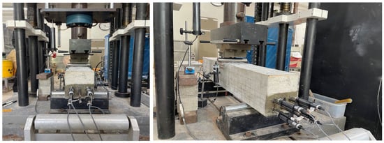
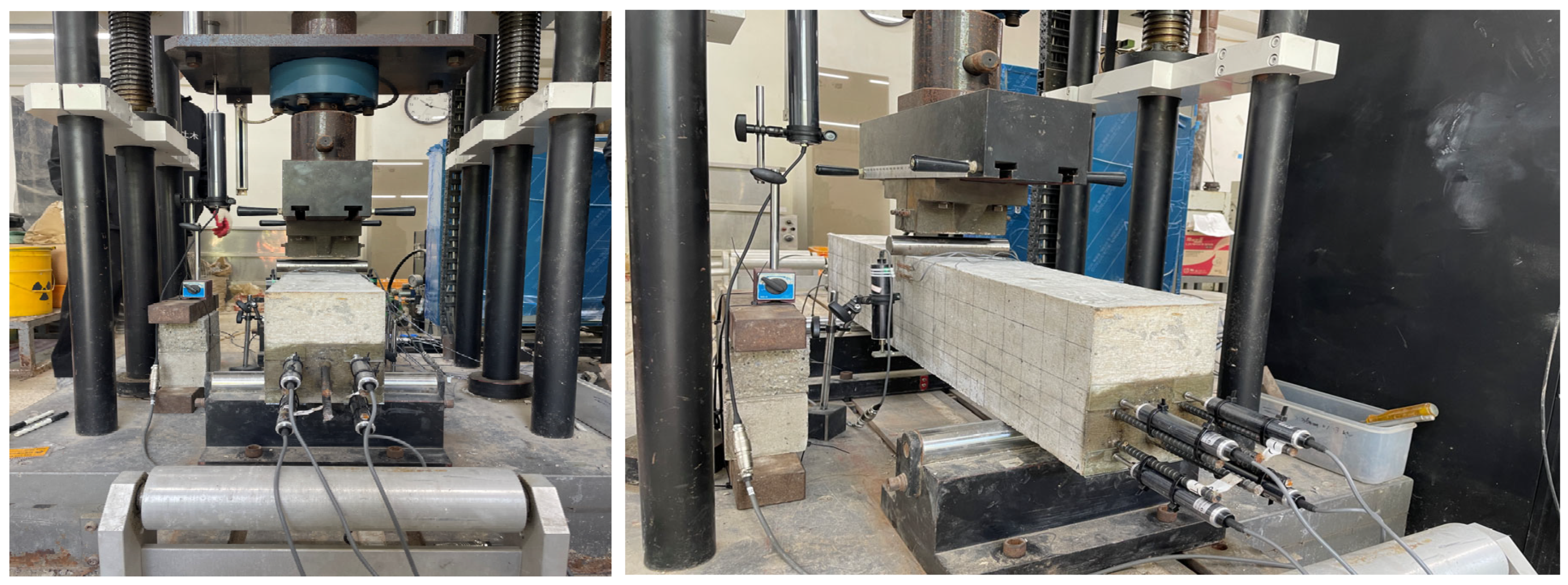
Figure 3 shows the actual experimental setup, including the straight anchorage of the CFRP bars, the support region, and the instrumentation for displacement and strain measurements.
Figure 3.
Shear-dominated member test setup and arrangement of horizontal LVDTs for test members.
3. Test Results
3.1. Deflection Behavior
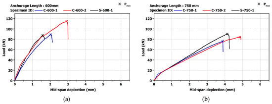
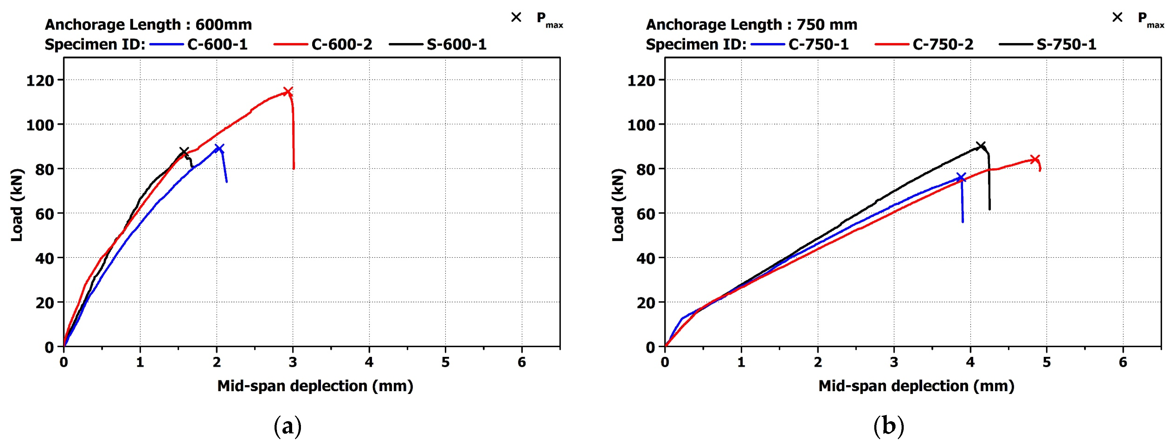
Figure 4 shows the experimental load–deflection curves determined using the LVDT measurements obtained at the midspan of all members. Figure 4a presents the case where the anchorage length is 600 mm, while Figure 4b shows the case where the anchorage length is 750 mm.
Figure 4.
Load–deflection curve: (a) anchorage length: 600 mm; (b) anchorage length: 750 mm.
As shown in Figure 4, regardless of the type of reinforcement, all members exhibited a slight change in flexural rigidity immediately after the initial crack occurred, followed by an increase in load without a significant change in slope until the maximum load was reached. Additionally, since there was no shear reinforcement, the members failed immediately after diagonal cracks formed, and the failure progressed rapidly under a relatively low load.
Meanwhile, among the 600 mm anchorage members, one CFRP member (C-600-2) achieved a notably higher ultimate load (114.7 kN) compared to its twin C-600-1 (89 kN) and the S-600-1 (86.7 kN). This variability underscores the inherent scatter in shear tests.
Nevertheless, both CFRP members exceeded the predicted shear capacity by a wide margin. The exceptionally high capacity of C-600-2 can be attributed to a combination of normal experimental scatter and the enhanced dowel action provided by the CFRP bars, which effectively bridged the shear cracks.
For RC members, regardless of anchorage length, a higher flexural rigidity was observed compared to CFRP members. This appears to be due to the superior elastic modulus of the rebar compared to CFRP. Meanwhile, in all test members, no significant yielding or sudden slip was observed, and no slip of the rebars was observed based on the LVDT measurements taken at both ends of the member. In other words, it was confirmed that shear failure occurred before slip, and that the failure followed the intended shear failure mode.
Table 4 shows the initial cracking load and maximum load and displacement for all members. It was observed that both the initial cracking load and ultimate load decreased, despite the increase in a/d from 2.7 to 3.7. Part of this reduction is attributed to the increased shear span (a), which leads to a larger a/d and thus a lower shear capacity. In other words, the a/d of 3.7 could not develop the same arching action as the a/d of 2.7. This likely contributed to their lower shear strength. This observation is consistent with the shear span effects noted in the literature—shorter spans (lower a/d) exhibit higher shear strength due to a partial arching action [18,19].
Table 4.
Comparison of experimental results of the members.
The ultimate loads of the CFRP members were of the same order as those of the RC members. This indicates that the tensile strength of the longitudinal reinforcement did not govern the failure in shear failures; the concrete mechanism dominate, so even an extremely high-strength bar like CFRP does not substantially increase the shear failure load relative to steel.
3.2. Relationship Between Load and Strain
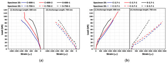
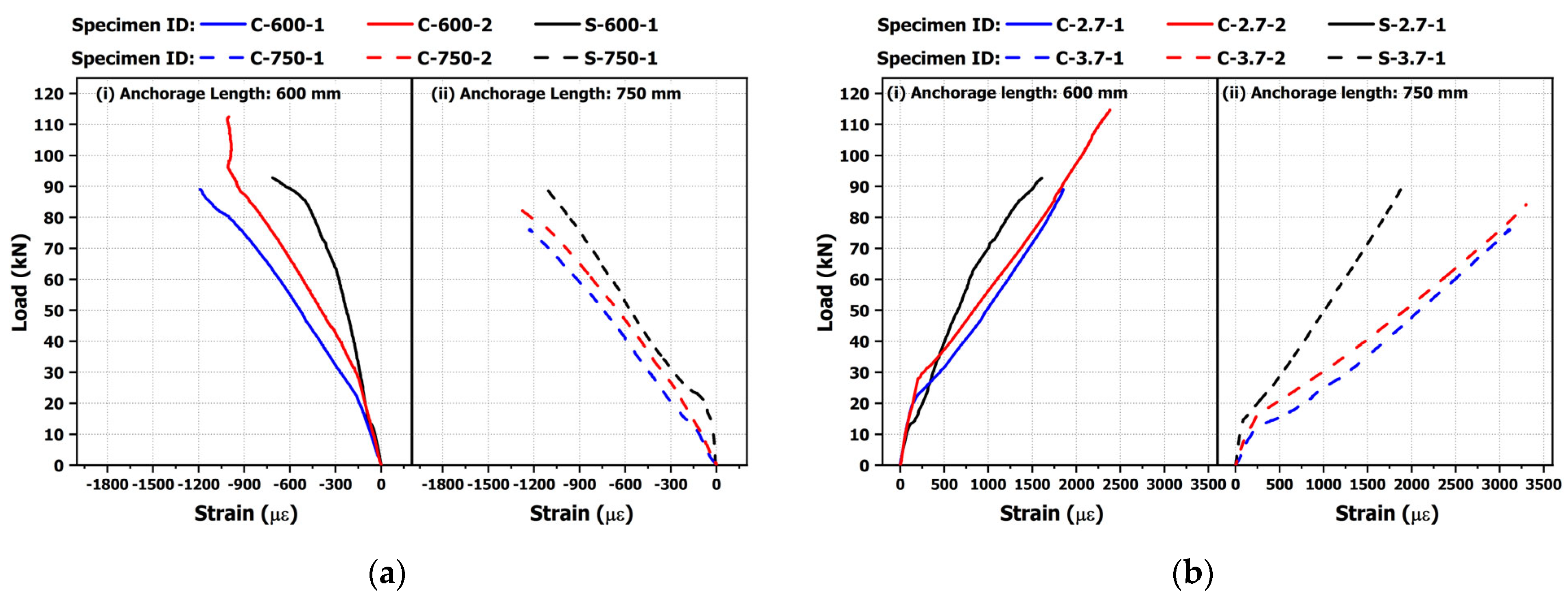
A concrete strain gauge placed 20 mm from the edge of the compressive zone in all members was used to measure the concrete strain. Additionally, a gauge was installed at the center of the main reinforcement to measure strain. The load–strain curves corresponding to the applied load levels of the members are shown in Figure 5.
Figure 5.
Load–strain curve: (a) concrete strain; (b) reinforcement strain.
The concrete strain is presented in Figure 5a. The strain increased linearly with the load, regardless of the type of reinforcement. Although there was a slight change in the slope after the initial crack occurred, the concrete strain in the CFRP members increased more than in RC members. This trend was not influenced by the change in the anchorage length. Additionally, the concrete strain was found to range from 1000 to 1500 με, which is less than half of 3300 με, despite the failure of the member, indicating a very high possibility of shear failure.
Moreover, the load–reinforcement strains shown in Figure 5b exhibit the same behavior observed in the load–deflection curves, with strain increasing linearly with the load. Furthermore, regardless of the anchorage length, all rebar strains remained below the yield strain, even at a maximum load. This trend was also observed when CFRP was used, indicating that the member exhibited shear behavior, as confirmed in the load–deflection curves.
3.3. Characteristics of Crack Pattern and Failure Mode
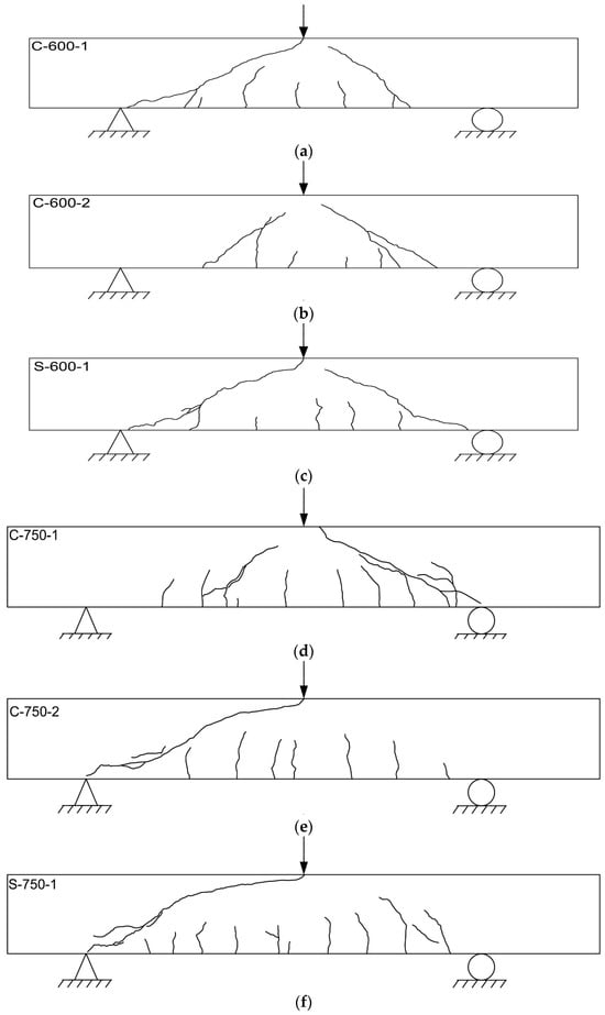
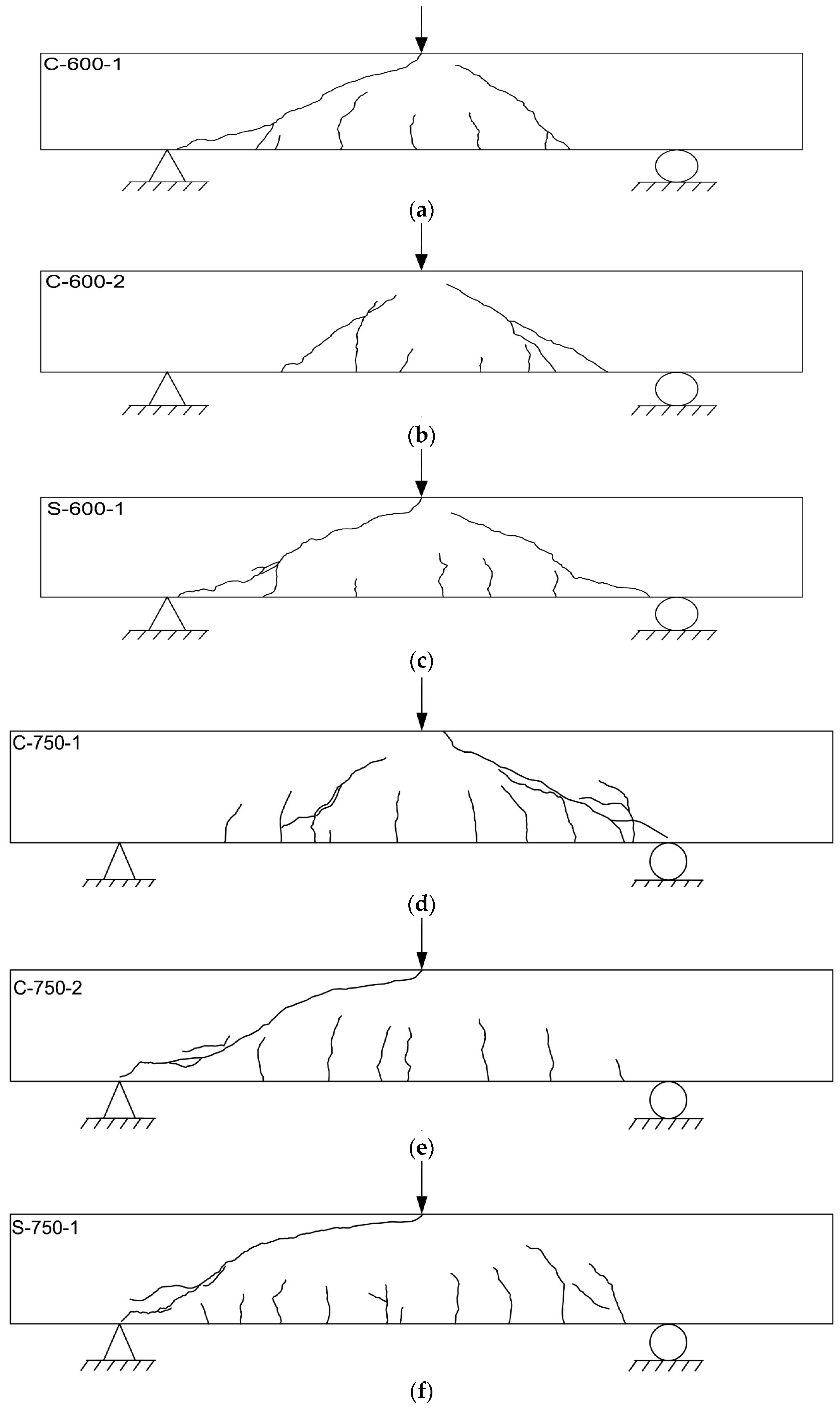
To evaluate the crack pattern, a crack map was drawn after the flexural test. Figure 6 shows a typical crack occurrence pattern observed in this test. From the results, cracking in all members began with the formation of flexural cracks, initiated by crack opening at the bottom center of the member, which then grew vertically. The load at this stage exhibited a similar trend to that shown in Table 4.
Figure 6.
Typical crack occurrence patterns: (a) C-600-1; (b) C-600-2; (c) S-600-1; (d) C-750-1; (e) C-750-2; (f) S-750-1.
Furthermore, the flexural cracks tended to progress toward the edge of the concrete in the compression zone. However, additional flexural shear cracks developed within the shear region, and, due to the dominance of shear stress, the cracks became increasingly inclined and propagated toward the loading point, eventually leading to diagonal cracks. Meanwhile, the flexural cracks that developed near the center of the member did not extend into the compressive zone as the load increased and ultimately led to failure. This indicated that the failure mode of the member was primarily governed by shear stress.
RC members (S-600-1, S-750-1) showed a tendency for the flexural cracks at the bottom center of the member to slightly increase compared to the CFRP members (C-600-1, C-600-2, C-750-1 and C-750-2).
4. Discussion
4.1. Shear Capacity
The failure load, the contribution of concrete to shear resistance (Vc,exp), and the normalized shear strength obtained from the experimental results are presented in Table 5. From the results, in CFRP members, the normalized shear strength () slightly decreased despite the anchorage length increase from 600 to 750 mm. As aforementioned, the increased anchorage length entailed an increase in the a/d; thus, the results were affected by this change. This reduction appears to be due to a decrease in the width of the concrete compression zone as a/d increased, which reduced the shear resistance. As described in the introduction, CFRP members appear to be slightly more affected by this reduction than those using rebar, likely due to the brittle material properties of CFRP compared to rebar.
Table 5.
Summary of test results.
Table 6 presents the calculation for the contribution of concrete to the shear resistance (Vc,cal) according to various design standards [20,21,22,23,24,25,26,27,28,29]. The parameters affecting the Vc—compressive strength, cross-sectional dimension, and so on—are generally included in these standards, irrespective of the reinforcement type. However, each design code exhibits distinct characteristics in determining the value of Vc. The characteristics of each model can be described as follows:
Table 6.
Parameter ranges of the concrete shear strength equations.
For CFRP, the ACI 440.1R-15 code determines Vc based on the compressive strength, reinforcement ratio, and strain of FRP; however, the size effects and a/d are not directly considered. Consequently, the accuracy of the predictive values is reduced under high compressive strength or special conditions, and the predictive results tend to be conservative [30].
The CSA-S806-12 code incorporates the reinforcement ratio and elastic modulus of FRP, but does not consider the size effects. It also underestimates the contribution of compressive strength (). Notably, it is the only code that accounts for the influence of the a/d in its predictive models for the Vc of CFRP members. Nevertheless, this code provides upper and lower limit criteria, and in this study the result was calculated based on the lower values.
CSA-S6-19 is a bridge design standard that can be applied when using rebar and CFRP bars. This model reflects size effects; however, despite the distinct mechanical properties between rebar and FRP, it does not include parameters that reflect these differences.
EC 2 reflects the size effects, reinforcement ratio, elastic modulus, and strain and elastic modulus ratios between rebar and CFRP to calculate the shear strength.
ISE (1999) reflects various parameters, such as the compressive strength, cross-section dimension, size effect, reinforcement ratio, and elastic modulus of CFRP, and the elastic modulus ratio between rebar and CFRP, to predict shear strength.
JSCE (1998) incorporates the empirical design equation that includes compressive strength, reinforcement ratio, size effects, and the ratio of the design flexural moment (Md) and real flexural moment (Mo) for predicting shear strength.
Among the standards, the Vc,cal for CFRP members calculated using CSA-S806-12 was the most conservative. This conservatism appears to be due to the limited consideration of the relationship between the ultimate shear force (Vu) and the bending moment, as well as the underrepresentation of concrete compressive strength. Additionally, CSA-S6-19 was similar to ACI 440.1R-15, so the results did not show a significant difference.
Additionally, the European code (EC2 and ISE) predicted a larger Vc,cal compared to ACI and Canada codes, as they considered the size effect. Specifically, EC2 predicted the highest Vc,cal value because it also factored in the effect of over-reinforcement. On the other hand, the JSCE (1998) model, unlike other prediction models, appears to provide a larger margin for Vc,cal by offering a calculation method specifically for cases where stirrups are not used. Moreover, the JSCE (1998) model did not account for the effect of anchorage length; however, the calculation results vary depending on the anchorage length because they reflect the influence of the design flexural strength (Md) and actual flexural strength (Mo), including Vc,cal for members without stirrups, which resulted in predicting a larger Vc,cal compared to other models.
For rebar, ACI 318-19 calculates Vc based on an empirical expression, with compressive strength, width, effective depth, and size effects as variables. However, it does not directly consider the a/d. Furthermore, there is no clear distinction between beam action and arch action. Due to these characteristics, ACI 318-19’s model is known for being simple and practical. However, it may diminish accuracy for high-strength concrete or deep beams and tends to provide conservative results [31,32].
CSA-A23.3-19 is based on the Modified Compression Field Theory (MCFT) proposed by Vecchio and Collins for calculating Vc [33]. Furthermore, β not only reflects the effects of the maximum size of coarse aggregate and cracks but also incorporates the size effects. The a/d is indirectly considered, distinguishing between deep beams and slender beams [34]. The predictive models of CSA-S6-19 and CSA-A23.3-19 have similar forms, and the design criteria provide an equation that can be applied to both rebar and FRP.
EC 2 for FRP also utilizes the strut-and-tied model to calculate the shear strength. As with the ACI 318-19 model, this model incorporates the reinforcement ratio for longitudinal reinforcement and the size effect. It explicitly accounts for emphasizing applicability to high-strength concrete [35]. Moreover, it should be noted that this shear strength is associated with the reinforcement concrete cross-section as a whole; thus, it differs from the shear strength of concrete alone [35].
The BS 8110 model is similar to ISE (1999). Additionally, it includes the factor , to consider the influence of a higher compressive strength on the shear strength. For deep beams (with a/d between 2 and 2.5), the increase in shear strength due to arching action is incorporated by multiplying the calculated shear strength by [36,37].
JSCE (2007) reflects empirical design equations with coefficients reflecting compressive strength, size effects, the reinforcement ratio, and axial force. This model emphasizes the arching action in deep beams, indirectly considering the a/d. This reflects the fact that the arching action serves as the primary failure mechanism in deep beams [38].
The prediction model of ACI 318-19 estimated Vc,cal to be larger than that of the Canadian code because it included a coefficient reflecting the size effect where stirrups were not used. Similarly, the European codes also reflected the size effect, as with CFRP, leading to relatively larger predictions. However, it was found that there was no significant difference between the prediction models, such as CFRP members.
Table 7 shows the results comparing the Vc,exp obtained from the experiments with the Vc,cal calculated according to the design standards. As a result, the Vc,cal obtained from the experiments are all higher than those predicted through the design criteria, indicating that the current prediction models are overly conservative. Overall, all CFRP members in our study showed a higher shear strength than was predicted by codes, but the degree of increase varied. Thus, while the enhanced dowel action appears to play a role, it should be investigated further.
Table 7.
Comparison of test results with the difference code predictions.
For CFRP members, the difference between the experimental results and the predicted results decreased in the following order, CSA-S806-12, ACI 440.1R-15, CSA-S6-19, ISE, JSCE (1998), and EC 2, regardless of anchorage length. The reason the experimental values were larger than the predicted values is that the contribution of concrete to the shear resistance in the prediction model was developed based on the assumption that stirrups are placed to secure shear resistance and continue contributing to the shear resistance even after cracking occurs. However, since stirrups were not placed in this study, it appears that the current design standards predict significantly lower shear resistance by excluding the contribution of stirrups, as well as the dowel action and aggregate interlocking.
In EC2, JSCE, and ISE, where the difference between Vc,cal and Vc,exp is relatively small, it was found that these models were developed based on the RC prediction model, along with the interaction between FRP and reinforcing bars (), and include a longitudinal reinforcement ratio that accounts for the effect of dowel action when estimating the shear strength of concrete (Vc). Therefore, to mitigate the difference between Vc,exp and Vc,cal, it is necessary to consider a longitudinal reinforcement ratio that reflects the effect of dowel action in other prediction models as well.
Nevertheless, the actual shear resistance of members is believed to be higher than the values predicted by the models. This is because shear resistance mechanisms, such as dowel action and aggregate interlocking, continue to contribute up to a certain level of load, even after cracking occurs. In addition, in this study, the actual reinforcement ratio was intentionally over-reinforced to induce shear failure, reaching 1.934%. Similarly, the CFRP members were reinforced beyond the balanced reinforcement ratio to induce brittle failure. It is therefore considered that most of the actual experimental results exceeded the predicted values due to the enhanced shear resistance effect from dowel action, as the over-reinforced reinforcement improved the dowel action contribution.
4.2. Characteristics of Anchorage Length
Table 8 presents the calculated required anchorage lengths based on the design standards used in the Vc prediction models [5,20,21,22,26,27]. Exceptions include the European models (EC 2, ISE), which do not clearly provide anchorage length requirements for CFRP members; the ISE model, which provides an anchorage length for RC members only; and the JSCE model, which provides anchorage length calculations only for cases where stirrups are used.
Table 8.
Parameter ranges of the anchorage length equation.
When CFRP is used as the main reinforcement, the anchorage lengths calculated using ACI 440.1R-15 range from 25.2% to 38.1% of the required anchorage lengths calculated using the other prediction models. This discrepancy may be influenced by the fact that the model does not reflect the specified tensile strength (ffr) of the reinforcement used in the prediction model (1800 MPa) but instead uses the modulus of elasticity and strain, leading to a lower specific ffr than 1800 MPa.
In contrast, the required anchorage length calculated using the Canadian model CSA-S6-19 was approximately 67% of the value calculated using CSA-S806-12. This difference is considered to be an underprediction, as the design code of CSA-S6-19 accounts for the effect of the elastic modulus, unlike CSA-S806-12.
When rebar was used as the main reinforcement, the anchorage length predicted using ACI 318-19 was approximately 30% of the anchorage length calculated using CSA-A23.3-14 and CSA-S6-19. It showed a similar trend to the required anchorage length calculations for CFRP members. The difference between the required anchorage lengths calculated using CSA-A23.3-19 and CSA-S6-19 was approximately 29 mm, suggesting that the Canadian models do not show a significant difference in the required anchorage length when the material properties of the reinforcement are the same. However, the large difference between the calculated results of the ACI and Canadian models is likely influenced by the inclusion of the tensile strength of CFRP in the design equations.
Table 9 compares the required anchorage lengths with the provided anchorage lengths of all members, where the values in parentheses below the required anchorage lengths indicate the ratio of the provided anchorage length to the required anchorage length.
Table 9.
Comparison of required anchorage length and provided anchorage length of members. (Note: N/A indicates that the corresponding code provision is not applicable to the specimen type).
For CFRP members, the required anchorage length calculated using ACI 440.1R-15 ranged from 132% to 166% of the provided anchorage length, indicating that the provided anchorage length satisfied the requirements of ACI 440.1R-15 regardless of the anchorage length-dependent a/d. However, the required anchorage length calculated based on Canadian standards was approximately 33% to 63% of the provided anchorage length. Generally, when a sufficient anchorage length is not secured, there is a high possibility of slip. However, in the CFRP member tests, no slip was observed even when the anchorage length required by the Canadian models was not fully satisfied. This result is attributed to the occurrence of shear failure before the flexural failure load was reached. Therefore, for shear-dominated members, the Canadian models appear to be overly conservative for the required anchorage length.
For RC members, the required anchorage length calculated using ACI 318-19 was approximately 142% to 177% of the provided anchorage length, satisfying the required anchorage length criteria. However, the required anchorage lengths calculated using the Canadian standards CSA-A23.3-14 and CSA-S6-19 were approximately 43% to 55% of the provided anchorage length. Despite this, no slip was observed in the RC members, indicating that, for shear-dominated behavior, the Canadian models may also impose an excessively conservative required anchorage length.
Meanwhile, Table 10 compares the provided anchorage lengths with the required anchorage lengths to develop the theoretical flexural capacity of each member. The results showed that, regardless of the type of reinforcement, the required anchorage lengths calculated using the U.S. design standards (ACI 440.1R-15 and ACI 318-19) underestimated the required anchorage length for shear failure, while the Canadian models overestimated the required anchorage length for shear failure, regardless of the reinforcement type.
Table 10.
Comparison of required development length and provided development length of members.
However, in all members, no slip was observed, even when the required anchorage lengths for shear failure specified by the Canadian models were not satisfied.
Therefore, since the prediction models commonly used for anchorage length estimation are based on flexural design to ensure sufficient flexural performance, it is considered that a sufficient resistance to anchorage failure can be provided even with a shorter anchorage length when the structural behavior is shear-dominated, regardless of the type of reinforcement.
The findings regarding shear capacity and the characteristics of anchorage length are interconnected. The improved shear capacity observed in the CFRP members, attributed to an enhanced dowel action, was possible because a sufficient anchorage length was maintained throughout the loading process. Although the provided anchorage lengths were shorter than the conservative requirements of the Canadian codes, they were adequate for preventing bond failure. This allowed the non-yielding CFRP bars to remain fully engaged with the surrounding concrete, enabling them to function as effective dowels and resist the diagonal cracks.
However, it is crucial to acknowledge that our findings are based on lab-scale, over-reinforced members under monotonic loading. Larger-scale elements often exhibit the well-known size effect [39,40,41], where the shear stress capacity decreases as the member depth increases. In FRP reinforced elements, the size effect can be pronounced because wider cracks and a lack of dowel yielding can reduce the aggregate interlock efficiency in larger members. Therefore, the conservatism observed in our study might not directly translate to full-scale bridge girders. In a larger member, the shear strength may decrease as the contribution of arching and dowel actions diminishes due to the size effect; therefore, relaxing anchorage length requirements in design standards based on the conservatism observed in lab-scale experiments requires a cautious approach and additional safety verification.
5. Conclusions
This study investigated the shear behavior of normal-strength concrete members reinforced with thread-wrapped CFRP bars without shear reinforcement subjected to monotonic loading. The experimental results were compared with theoretical predictions based on current design standards. The key conclusions are as follows:
- (1)
- All members, regardless of the reinforcement type and anchorage length, exhibited a higher ultimate shear strength (Vu) than the predicted concrete shear strength (Vc). This outcome is primarily attributed to the enhanced dowel action resulting from the over-reinforcement in the CFRP members, an effect that is conservatively neglected in the current design standards.
- (2)
- The anchorage length provisions based on flexural failure modes are overly conservative and inefficient for shear-dominated members. This was demonstrated by the fact that no slip or anchorage failure was observed in any member, even with provided anchorage lengths shorter than the code requirements.
- (3)
- For shear-dominated members, it was found that the main factors considered in calculated concrete shear strength (Vc,cal) differ among the design standards of various countries. Therefore, it is necessary to identify the key factors that significantly influence shear behavior and apply appropriate design standards to accurately reflect them.
- (4)
- Therefore, Vc prediction models, such as ACI 440.1R-15, CSA-S806-12, and CSA-S6-19, could be improved by incorporating factors that reflect the enhanced dowel action and residual shear mechanisms in members without stirrups. In particular, parameters like the longitudinal reinforcement ratio, bar diameter, and concrete strength (which influence dowel action and interlock action) should be included in shear capacity formulations to reduce over-conservatism.
Author Contributions
Data curation, S.Y.C.; formal analysis, S.Y.C.; writing—original draft, S.Y.C.; methodology, I.S.K.; investigation, I.S.K.; funding acquisition, E.I.Y.; supervision, E.I.Y.; writing—review and editing, E.I.Y. All authors have read and agreed to the published version of the manuscript.
Funding
This research was supported by Basic Science Research Program through the National Research Foundation of Korea (NRF) funded by the Ministry of Education (2021R1A6A1A03044326).
Data Availability Statement
Data sharing does not apply to this article as no datasets were generated or analyzed during the current study.
Conflicts of Interest
The authors declare no conflicts of interest.
References
- Basaran, B.; Donmez, E.T. Effects of fibre wrapping degree and ratio on the tensile properties of carbon FRP-steel hybrid reinforcements. J. Build. Eng. 2023, 76, 107189. [Google Scholar] [CrossRef] [Scilit]
- Liang, L.; Ke, L.; Feng, Z.; Li, C.; Yan, B.; Guo, J. Experimental and theoretical study on the shear behavior of CFRP bar-reinforced UHPFRC beams considering orientation and volume fraction of steel fibers. Arch. Civ. Mech. Eng. 2023, 24, 1. [Google Scholar] [CrossRef] [Scilit]
- Jung, S.; Kim, K.S. Knowledge-based prediction of shear strength of concrete beams without shear reinforcement. Eng. Struct. 2008, 30, 1515–1525. [Google Scholar] [CrossRef] [Scilit]
- Ahmad, S.; Bhargava, P. Shear Strength Models for Reinforced Concrete Slender Beams: A Comparative Study. Structures 2018, 16, 119–128. [Google Scholar] [CrossRef] [Scilit]
- CAN/CSA S6-14; Canadian Highway Bridge Design Code. Canadian Standard Association: Toronto, ON, Canada, 2014.
- Liu, J.; Mihaylov, B.I. A comparative study of models for shear strength of reinforced concrete deep beams. Eng. Struct. 2016, 112, 81–89. [Google Scholar] [CrossRef] [Scilit]
- Dinh, N.H.; Roh, Y.-S.; Truong, G.T. Shear strength model of FRP-reinforced concrete beams without shear reinforcement. Structures 2024, 64, 106520. [Google Scholar] [CrossRef] [Scilit]
- Elghandour, B.; Eltahawy, R.; Shedid, M.; Abdelrahman, A. Prediction of shear strength for CFRP reinforced concrete beams without stirrups. Eng. Struct. 2023, 284, 115946. [Google Scholar] [CrossRef] [Scilit]
- Zhang, Y.-X.; Hu, K.-Y.; Zeng, J.-J.; Hou, W. Long-term bond performance of fiber-reinforced polymer (FRP) bars to concrete in marine environments: A comprehensive review. Arch. Civ. Mech. Eng. 2025, 25, 118. [Google Scholar] [CrossRef] [Scilit]
- Oukaili, N.; Allawi, A.A.; Issa, M.A.; Said, A.I.; AlBayati, A.; Ibrahim, T.H.; Wardeh, G. On the effectiveness of shear reinforcement type in GFRP-reinforced concrete beams: Experimental study. Struct. Concr. 2025, 26, 6547–6575. [Google Scholar] [CrossRef] [Scilit]
- Abdallah, W.; Farrag, A.M.; Deifalla, A.F.; Ibrahim, A.H.; Mohamed, H.M.; Ali, A.H. Shear Performance of GFRP Reinforced Concrete Beams with Seawater and Chopped Fiber. Civ. Eng. J. 2023, 9, 835–848. [Google Scholar] [CrossRef] [Scilit]
- ASCE-ACI Committee 445 on Shear and Torsion. Recent Approaches to Shear Design of Structural Concrete. J. Struct. Eng. 1998, 124, 1375–1417. [Google Scholar] [CrossRef] [Scilit]
- Yoo, S.-J.; Hong, S.-H.; Yoon, Y.-S. Bonding behavior and prediction of helically ribbed CFRP bar embedded in ultra high-performance concrete (UHPC). Case Stud. Constr. Mater. 2023, 19, e02253. [Google Scholar] [CrossRef] [Scilit]
- ASTM D7205/D7205M-21; Standard Test Method for Tensile Properties of Fiber Reinforced Polymer Matrix Composite Bars. ASTM International: West Conshohocken, PA, USA, 2021.
- ASTM E8/E8M-24; Standard Test Methods for Tension Testing of Metallic Materials. ASTM International: West Conshohocken, PA, USA, 2024.
- ASTM C39/C39M-24; Standard Test Method for Compressive Strength of Cylindrical Concrete Specimens. ASTM International: West Conshohocken, PA, USA, 2024.
- ASTM C469/C469M-22; Standard Test Method for Static Modulus of Elasticity and Poisson’s Ratio of Concrete in Compression. ASTM International: West Conshohocken, PA, USA, 2022.
- Sagaseta, J.; Vollum, R.L. Shear design of short-span beams. Mag. Concr. Res. 2010, 62, 267–282. [Google Scholar] [CrossRef] [Scilit]
- Hu, B.; Wu, Y.-F. Effect of shear span-to-depth ratio on shear strength components of RC beams. Eng. Struct. 2018, 168, 770–783. [Google Scholar] [CrossRef] [Scilit]
- ACI 440.1R-15; Guide for the Design and Construction of Structural Concrete Reinforced with Fiber-Reinforced Polymer Bars. American Concrete Institute: Detroit, MI, USA, 2015.
- CAN/CSA S806–12; Design and Construction of Building Structures with Fiber Reinforced Polymers. Canadian Standard Association: Toronto, ON, Canada, 2012.
- CAN/CSA S6-19; Canadian Highway Bridge Design Code. Canadian Standard Association: Toronto, ON, Canada, 2019.
- EN 1992-1-1; Eurocode 2: Design of Concrete Structures—Part 1-1: General Rules and Rules For Building. CEN: Brussels, Belgium, 2004.
- ISE-1999; Interim Guidance on the Design of Reinforced Concrete Structures Using Fiber Composite Reinforcement. Institution of Structural Engineers: London, UK, 1999.
- JSCE. Recommendation for Design and Construction of Concrete Structures Using Continuous Fiber Reinforcing Materials; Japan Society of Civil Engineers: Tokyo, Japan, 1998. [Google Scholar]
- ACI 318-19(22); Building Code Requirements for Structural Concrete and Commentary (Reapproved 2022). American Concrete Institute: Farmington Hills, MI, USA, 2019.
- CSA-A23.3-19; Design of Concrete Structures. Canadian Standard Association: Toronto, ON, Canada, 2019.
- BS 8110; Structural Use of Concrete. Part I: Code of Practice for Design and Construction. British Standards Institution: London, UK, 1997.
- JSCE. Standard Specifications for Concrete Structures “Design”; Japan Society of Civil Engineers: Tokyo, Japan, 2007. [Google Scholar]
- Tarawneh, A.N.; Saleh, E.F.; Alghossoon, A.M.; Almasabha, G.S.; Alajarmeh, O.S.; Manalo, A.; Benmokrane, B. Modified Shear Design Model for Steel- and Fiber- Reinforced Polymer-Reinforced Concrete Beams. ACI Struct. J. 2024, 121, 147–158. [Google Scholar] [CrossRef] [Scilit]
- Rasheed, M. Shear Behaviour in Reinforced Concrete Beams: Mechanisms, Failure Modes, and Predictive Models: A Review. Al Rafidain J. Eng. Sci. 2024, 2, 210–227. [Google Scholar] [CrossRef] [Scilit]
- Abdullah, M.; Qazi, A.U.; Khan, Q.S.; Kazmi, S.M.S.; Munir, M.J. Comparative Assessment of Shear Strength Equations for Reinforced Concrete. J. Struct. Des. Constr. Pract. 2022, 27, 04021082. [Google Scholar]
- Shaoyun, S.; Kuchma, D.A. Shear Behavior and Capacity of Large-Scale Prestressed High-Strength Concrete Bulb-Tee Girders (NSEL-002); Department of Civil and Environment Engineering; University of Illinois Urbana-Champaign: Champaign, IL, USA, 2007. [Google Scholar]
- Li, S.; Wu, Z.; Zhang, J.; Xie, W. Experimental Study and Calculation Methods of Shear Capacity for High-Strength Reinforced Concrete Full-Scale Deep Beams. Materials 2022, 15, 6017. [Google Scholar] [CrossRef] [Scilit]
- Bogdandy, B. The shear resistance of a member without shear reinforcement according to Eurocode 2; the error of the calculated value and the mechanical explanation of the problem. Int. Rev. Appl. Sci. Eng. 2021, 12, 222–229. [Google Scholar] [CrossRef] [Scilit]
- Harry, O.A.; Ekop, I.E. A Comparative Analysis of Codes Prediction of Shear Resistance in Beams without Shear Reinforcement. Am. J. Civ. Eng. Archit. 2016, 4, 39–43. [Google Scholar]
- Vollum, R.L.; Fang, L. Shear enhancement near supports in RC beams. Mag. Concr. Res. 2015, 67, 443–458. [Google Scholar] [CrossRef] [Scilit]
- Nakamura, H.; Iwamoto, T.; Fu, L.; Yamamoto, Y.; Miura, T.; Gedik, Y.H. Shear Resistance Mechanism Evaluation of RC Beams Based on Arch and Beam Actions. J. Adv. Concr. Technol. 2018, 16, 563–576. [Google Scholar] [CrossRef] [Scilit]
- Ashour, A.F.; Kara, I.F. Size effect on shear strength of FRP reinforced concrete beams. Compos. Part B Eng. 2014, 60, 612–620. [Google Scholar] [CrossRef] [Scilit]
- Alam, M.S.; Hussein, A. Size effect on shear strength of FRP reinforced concrete beams without stirrups. J. Compos. Constr. 2013, 17, 507–516. [Google Scholar] [CrossRef] [Scilit]
- Di, B.; Zheng, Y.; Zhou, L.; Tang, Y.; Zeng, J.; Wang, H. Shear behaviour of SWSS-SCC deep beams reinforced with GFRP longitudinal bars and CFRP strip stirrups. Eng. Struct. 2026, 346, 121692. [Google Scholar] [CrossRef] [Scilit]

Disclaimer/Publisher’s Note: The statements, opinions and data contained in all publications are solely those of the individual author(s) and contributor(s) and not of MDPI and/or the editor(s). MDPI and/or the editor(s) disclaim responsibility for any injury to people or property resulting from any ideas, methods, instructions or products referred to in the content. |
© 2026 by the authors. Licensee MDPI, Basel, Switzerland. This article is an open access article distributed under the terms and conditions of the Creative Commons Attribution (CC BY) license.