


Abstract
Origami is frequently used in the design of deployable structures due to its large storage ratio and simple structure. A bistable characteristic is a common feature of origami-inspired structures. In this paper, a new configuration is designed with a bistable characteristic; the forming behavior and restoration process were investigated by experimental and finite element methods. The rod system was used to prove the bistable characteristic of the configuration; meanwhile, the geometric parameter analysis was used to analyze the bistable characteristic under different geometry parameters, including external border, initial angle, and displacement, respectively. An experimental test and finite element simulation for morphological changes and force–displacement curve characteristics were investigated during the forming and recovery process. The results show that the designed configuration has a bistable characteristic: it can be formed and recovered actively, and the finite element simulation and experimental results are consistent.
1. Introduction
Origami [1,2,3,4], the art of paper folding, has many advantages compared with traditional mechanisms [5,6,7,8], such as strong mobility and storability, which were widely used in vibration isolator [9,10], medical instruments [11,12,13], aerospace [14,15,16], intelligent robots [17,18,19], metamaterials [20,21,22,23], and other fields [24,25,26,27]. Different from origami, kirigami allows the introduction of a cutting line in the design, thus further enhancing the variability of obtainable shapes [28]. Compared to origami structures, designs inspired by kirigami could achieve a greater deformation and enhance ductility properties, increasing the variability and diversity of achievable design configurations [29,30]. Deng et al. [31] studied a laser-magnetic-edited composite film. With the help of a laser and magnetic field, the direction of magnetic particles in the configuration is preset, so as to realize the reconstruction characteristics and show the application of multistate electrical switches and magnetic soft robots. Therefore, it is of great significance to study the reconfiguration of kirigami and apply its unique advantages to advanced fields.
Rotational Erection System (RES), a kirigami structure, is proposed by the Japanese scholar Miyamoto [32], which consists of the center hub, the arm, and the tab through a reasonable creases-and-cuts arrangement, forming a three-dimensional structure by rotating and rising. Lee et al. [33] designed a frequency-reconfigurable triple-tower monopole antenna that is similar to the RES structure using a PET (Polyethylene Terephthalate) film material engineered in a kirigami structure. Duan et al. [34] proposed a rotating erection kirigami structure (REKS) that can improve the energy absorption efficiency. The finite element model was developed to investigate the effects of structural parameters on mechanical performance. Yoneda et al. [35] investigated the mechanical properties of a threefold symmetric elastic RES by combining finite element analysis and a physical experiment. The energy barrier for the bistability is quantified, which indicates that it is independent of the entire structure’s span but depends solely on its aspect ratio.
The active forming and shape recovery [36] of kirigami structures could be applied to obtain complex geometries by means of reversible structural deformations. To form the kirigami configuration from the planar to the three-dimensional state, three different forming methods are generally adopted: (i) Based on large deflections and post-buckling [37] deformation principles, the two-dimensional configuration is transformed into three-dimensional by torsion [38]. (ii) A tensile force [39] is applied to the planar kirigami to induce its out-of-plane buckling and yield a three-dimensional structure. (iii) The self-assembly of a three-dimensional configuration is realized by applying pre-strain [40,41] on the matrix of planar kirigami and buckling deformation of the configuration by pre-strain driving. Furthermore, researchers have explored a new approach that makes use of physical field changes, such as electric field [42], magnetic field, and temperature field [43], to drive the configuration transformations from planar sheets to 3D structures.
Bistability or multistability is a common feature of origami patterns and origami-inspired structures [44]. The structure may shift away from one stable state to another under the application of load or external mechanical perturbations, together with shape and energy changes [45]. Sharma et al. [46] investigated the mathematical and experimental investigations of the bistable behavior of the conical Kresling pattern. A systematic experimental methodology is introduced to investigate the quasistatic behavior, and a mathematical investigation based on the energy approach was introduced to develop quantitative stability maps for conical Kresling structures. Zhang et al. [47] designed a shape-reconfigurable metamaterial with high bearing force and low switching force. These features make the multistable structure an ideal platform for applications like soft robotics, energy adsorption, energy harvesting, vibration control, mechanical switches, and many more [48,49,50]. In order to design such systems, a proper investigation of the deployment behavior, including the number and position of stable states, is necessary.
In this paper, a new configuration is designed with a bistable characteristic; the forming behavior and restoration process were investigated by experimental and finite element methods. In Section 2, a rod-system model (an analysis method that simplifies the model into several rods, with no relative linear displacement in their intersection) was used to prove the bistable characteristics of the configuration. Meanwhile, the bistable characteristic was investigated under different geometry parameters, including external border, initial angle, and displacement, respectively. In Section 3, the stretching forming process and recovery process were investigated experimentally. In Section 4, the finite element method was used to simulate the stretching forming process and recovery process, which contrast with the experimental results. Finally, we discuss the geometric analysis and conclude the whole research.
2. Configuration Analysis
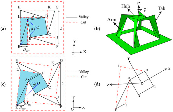
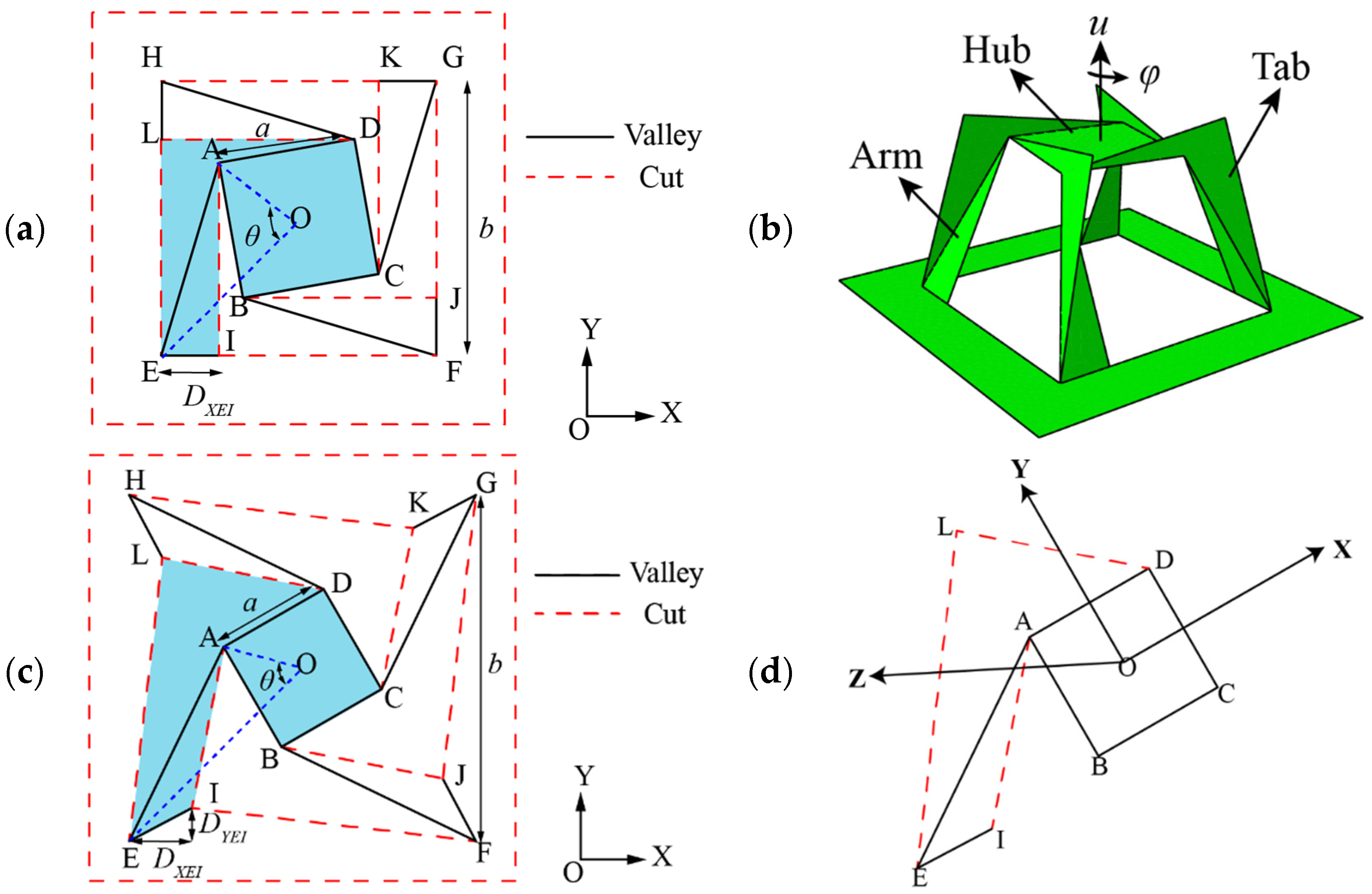
The classic Rotational Erection System (RES) configuration is shown in Figure 1a. The solid black line is the valley crease, the red dotted line is the cutting line, and the basic components of the configuration are the center hub, the tab, and the arm. The motion of the configuration is that the arm rotates upright; the center hub rotates and rises in the deployment process. Therefore, the motion parameters are rising displacement u and rotation angle φ of the center hub, as shown in Figure 1b.
Figure 1.
(a) RES configuration plane state; (b) RES configuration-unfolded state; (c) the designed configuration plane state; (d) a quarter of the designed configuration.
With RES as a reference, this paper designs a new configuration by changing the positions of I, J, K, and L. The geometric parameters of the configuration are the center hub length a, external border b, initial angle θ, and displacement DYEI and DYEI, which are marked in Figure 1c. In order to take convenience for analysis, a quarter of the configuration was removed and the coordinate system was established. The plane ABCD is the XOY plane, with the Z direction is out of the XOY plane and perpendicular to the XOY plane, as shown in Figure 1d.
2.1. Bistable Analysis
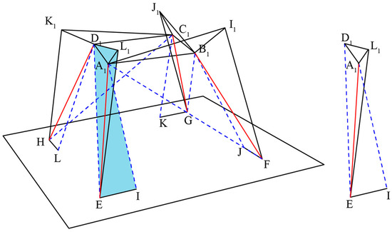
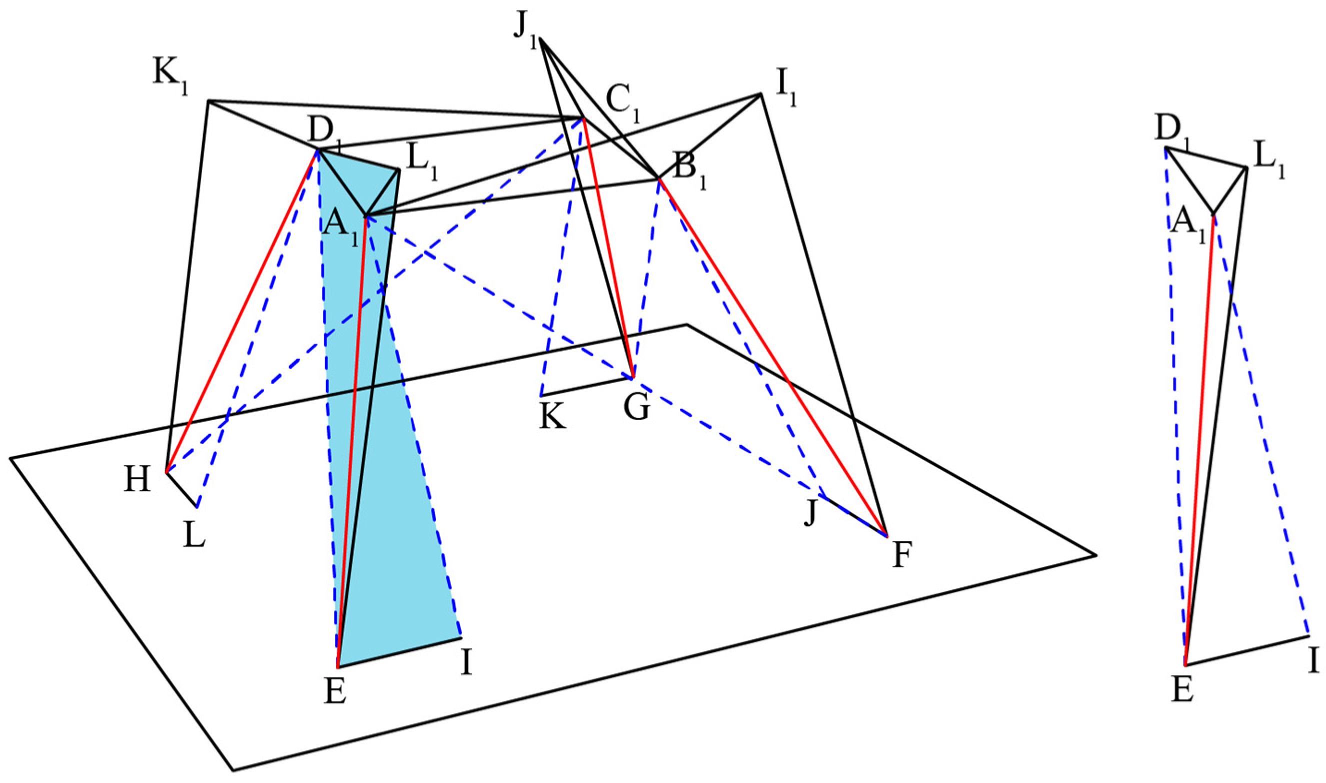
Based on the rod-system method, the designed configuration was simplified as Figure 2, and the right picture is a quarter of the rod-system method of the designed configuration. To simplify the analysis, it is common to assume that certain edge lengths remain constant and to evaluate the incompatibility of other assumed members during motion [51,52,53]. Their length changes can be regarded as a simplified surrogate measure of the overall panel deformation. The research hypothesis is that the length of the rod, represented by the solid line, is constant during the motion, so the deformation of the arm and the tab can be depicted as the deformation of the rod AI and rod ED, which are ΔLAI and ΔLED, respectively. In the motion process, the total energy of the configuration is related by ΔLAI2 + ΔLED2, and the initial vectors are
Figure 2.
The rod-system model of the RES configuration.
The point D is obtained by the point A rotating 90° clockwise around the origin, and the rotation matrix T1 is
and the vector and can be written as
The point L is obtained by the point I rotating 90° clockwise around the origin, and the vector is
In the motion process, with the center hub rotating and rising, the point A is changed to A1, while the point D is changed to D1,
where Tφ is the counterclockwise rotation matrix
Because of the hypothesis we mentioned earlier, the length of rod AE is a constant; meanwhile, assuming that LAE = LA1E, the relationship between u and φ can be obtained. So,
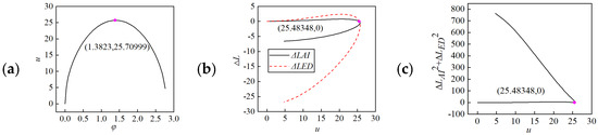
Given the geometric parameters are a = 20 mm, b = 40 mm, θ = −80° (clockwise is positive), DXEI = 8.45 mm, and DYEI = 0 mm, the relationship of φ-u, u-ΔL, and u-ΔLAI2 + ΔLED2 is shown in Figure 3.
Figure 3.
Parameter relationships: (a) φ-u; (b) u-ΔL; (c) u-ΔLAI2 + ΔLED2.
The rising displacement u of the center hub increases first and then decreases with a maximum value, which indicates that the configuration is fully expanded at the maximum value. The deformation of the rod AI and AE is not always equal to zero; it is explained that the arm and the tab are both non-rigid panels, and there are some plane deformations in the motion process. When u increases to the maximum value, ΔLAI2 + ΔLED2 decreases to zero, which implies the total energy of the configuration is zero, the configuration is in a stable state, and it is proven that the RES is a bistable configuration.
2.2. Geometric Parameter Analysis
In this section, on the basis of the geometric parameters mentioned in Section 2.1, the geometric parameters a/b, θ, DXEI, and DYEI were changed for analysis. The single variable method is used to explore the relationship between geometric parameters and configuration deformation.
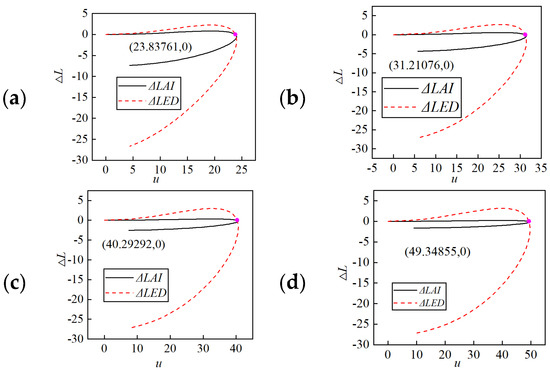
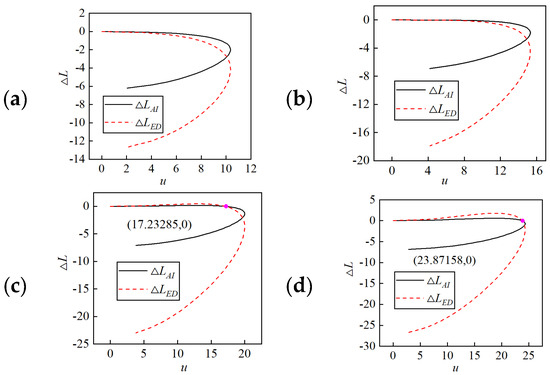
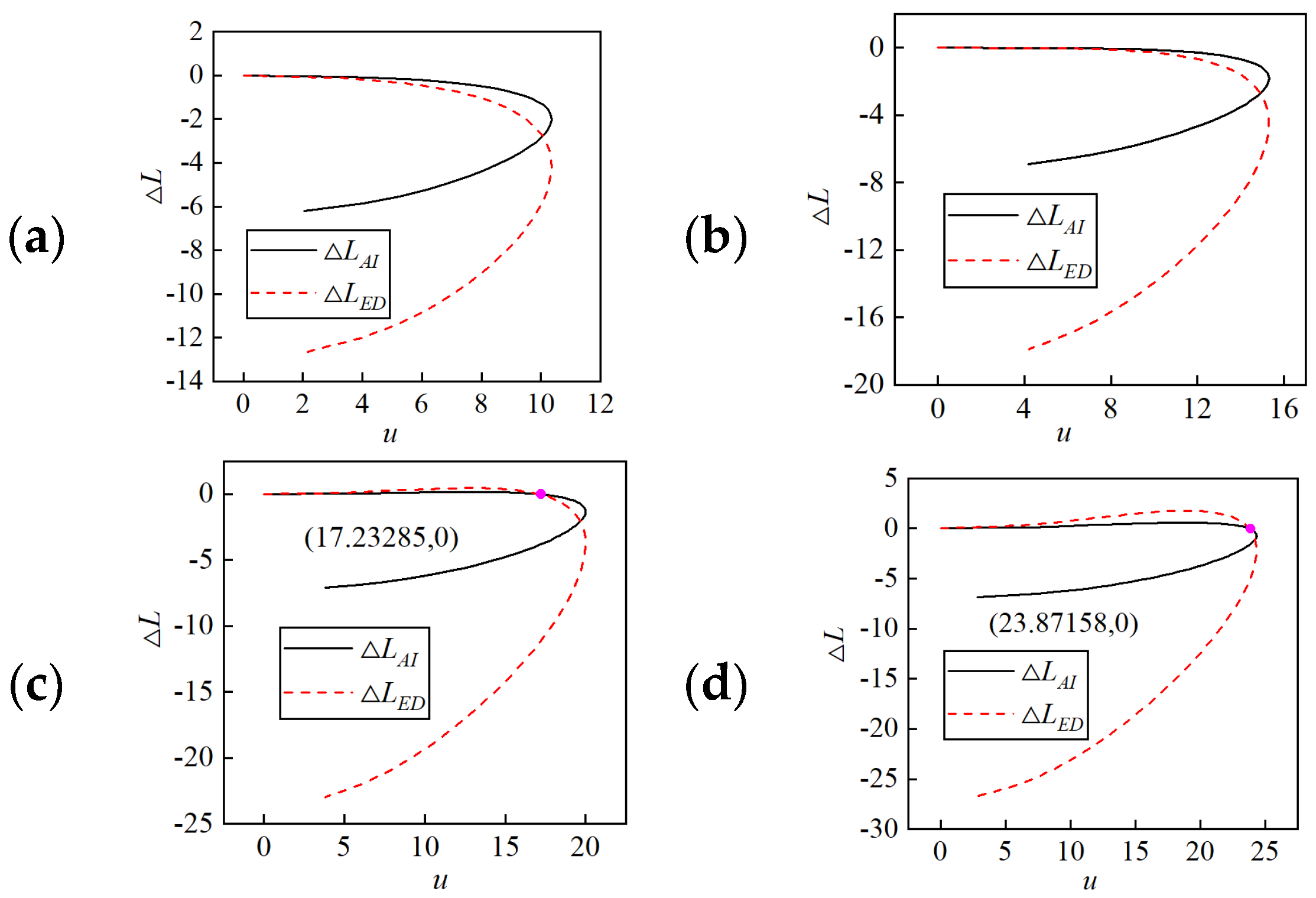
Firstly, taking the a/b as a variable, we just change the b to investigate the relationship of u-ΔL, as shown in Figure 4. We can find that as the external border increases, the maximum value of u increases, the slope increases in the curve of ΔLAI, and the opening becomes smaller. Both curves have an intersection point, and the ordinate is zero. It is indicated that the configuration has bistable characteristics. Then, taking the θ as a variable, it is found that the maximum value of ΔLED decreases to zero as the initial angle increases, and in the curve of ΔLAI, the slope increases and the opening becomes smaller, as shown in Figure 5. The two curves have intersection points and the ordinate is zero, which indicates the configuration has bistable characteristics while θ = 60° and θ = 75°.
Figure 4.
Relationship of u-ΔL under different external border values: (a) b = 35 mm; (b) b = 60 mm; (c) b = 100 mm; (d) b = 150 mm.
Figure 5.
Relationship of u-ΔL under different initial angle values: (a) θ = 30°; (b) θ = 45°; (c) θ = 60°; (d) θ = 75°.
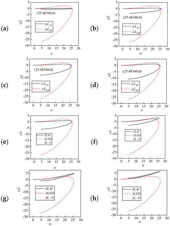
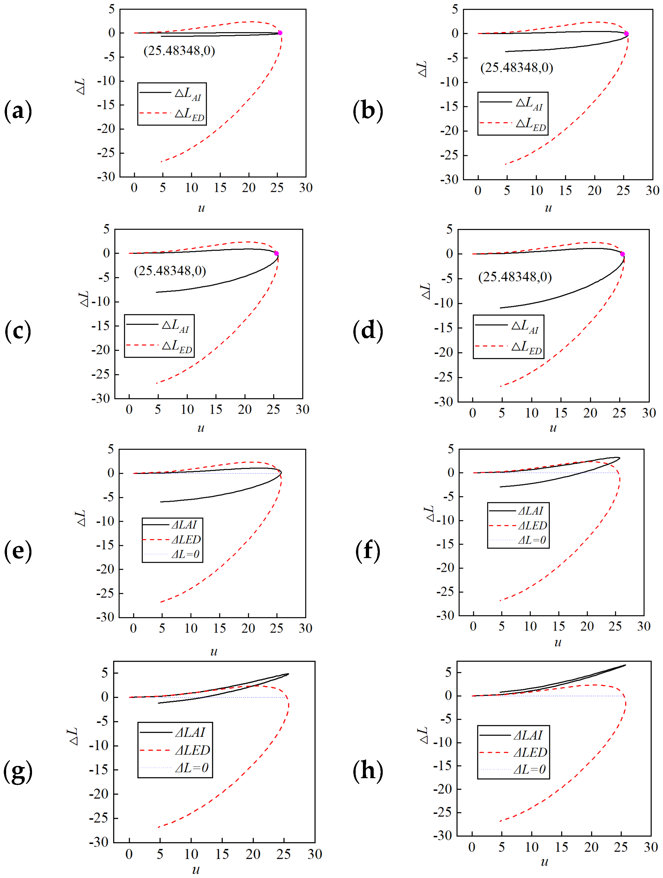
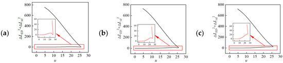
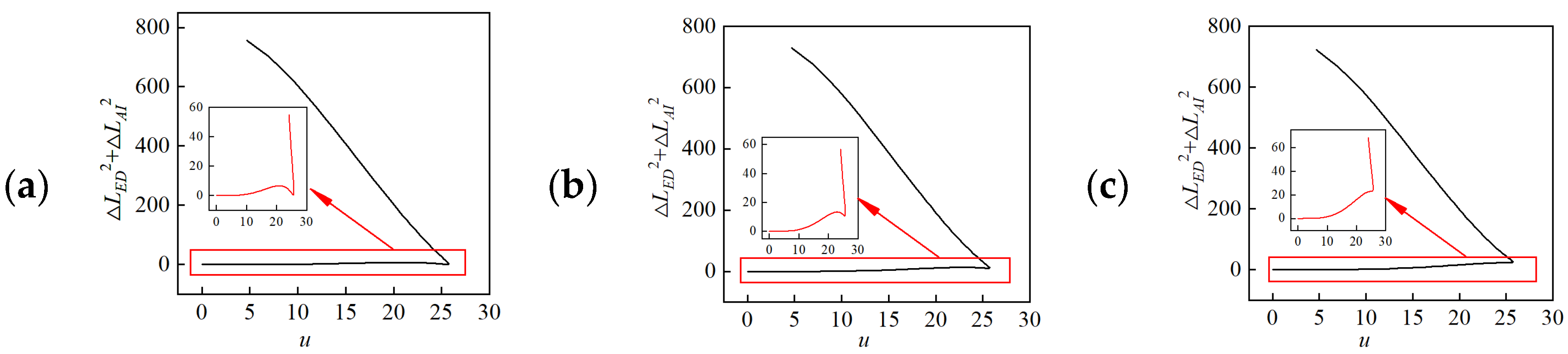
Thirdly, taking the DXEI as a variable, it is found that as the displacement increases, the curve of ΔLED remains almost unchanged, and in the curve of ΔLAI, the slope decreases and the opening becomes bigger, as shown in Figure 6. Both the two curves have an intersection point, and the ordinate is zero. It is indicated that the configuration has bistable characteristics. And finally, taking the DYEI as a variable, it is found that as the displacement increases, the curve of ΔLED remains almost unchanged, and the curve of ΔLAI rises gradually, the slope increases, and the opening becomes smaller. The two curves have intersection points, and the ordinate is more than zero, which needs further determination from the total energy while DYEI = 1, DYEI = 5, and DYEI = 7. It can be seen from the energy curve that there are obvious minimum points that indicate the configuration has bistable characteristics while DYEI = 1 and DYEI = 5, as shown in Figure 7.
Figure 6.
Relationship of u-ΔL under different displacement values: (a) DXEI = 1; (b) DXEI = 5; (c) DXEI = 10; (d) DXEI = 13; (e) DYEI = 1; (f) DYEI = 5; (g) DYEI = 7; (h) DYEI = 9.
Figure 7.
Relationship of u-ΔLAI2 + ΔLED2 under different displacement values: (a) DYEI = 1; (b) DYEI = 5; (c) DYEI = 7.
3. Experimental Analysis
In this section, the experimental forming process and recovery process were investigated. The forming process is divided into top stretch forming, which exerts the force on the top of the model, and diagonal stretch forming, which exerts the force on the diagonal of the model. The recovery process is divided into general recovery, which exerts the force on the top of the model, and arching recovery, which exerts the force out of plane to make the model buckle into an arch. Due to difficulty in exerting the load on the model in arching recovery, this section does not contain the arching recovery process.
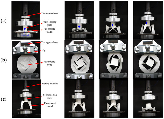
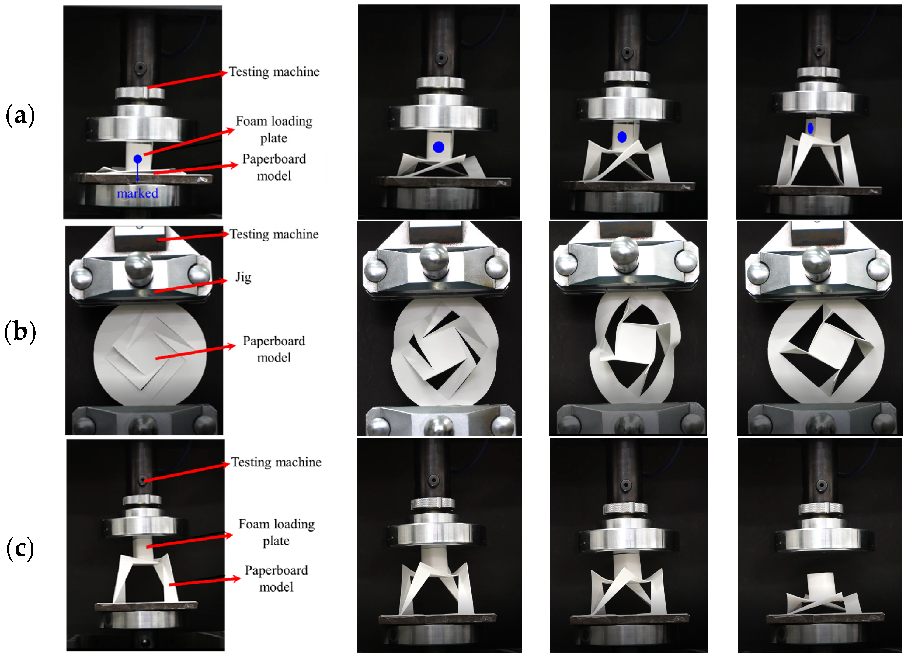
The paper model was tested by a stretch forming experiment, which was subdivided into top stretch forming and diagonal stretch forming experiments, as well as a general recovery experiment, as shown in Figure 8a–c, respectively. The model is made of YUPO QJJ500 synthetic paper with a thickness of 0.5 mm. The geometric parameters are a = 30 mm, b = 60 mm, θ = −80°, DXEI = 14 mm, and DYEI = 0. A universal testing machine was used to carry out the test, a lightweight foam loading plate was added at the center hub, and a pair of jigs was used for loading. The displacement loading method is adopted.
Figure 8.
(a) Top stretch forming experiment; (b) diagonal stretch forming experiment; (c) general recovery experiment.
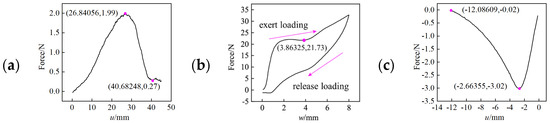
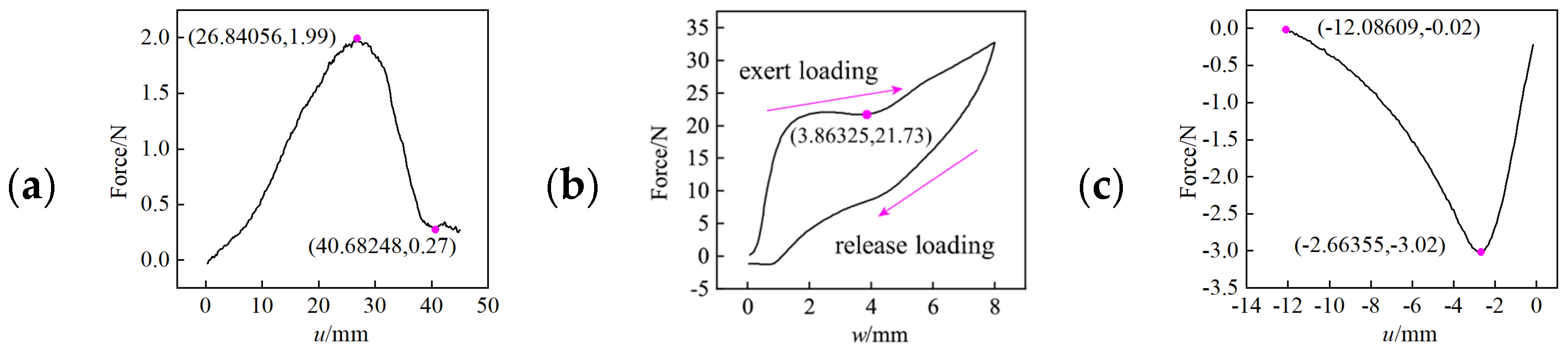
In the top stretch forming experiment process, a vertical upward displacement u = 45 mm is applied to the central hub of the configuration to shift it from the plane state to forming state. The morphological changes in the paper model and the curve of load–displacement during loading are shown in Figure 8a and Figure 9a, respectively. During the loading process, the model is gradually formed from a plane into three dimensions, and the center hub rotation can be seen from the blue-marked plane. It can be seen from Figure 9a that the maximum tensile force is 1.99 N. It is indicated that the model can be stretched when a force greater than 1.99 N is applied to the top of the model. The stiffness of the model at u = 40.68 mm drops to the minimum value, indicating that the configuration is already formed and in a stable state after the displacement load is released.
Figure 9.
(a) Force–displacement curve undergoing top stretch forming; (b) force–displacement curve undergoing diagonal stretch forming; (c) force–displacement curve undergoing general recovery.
In the diagonal stretch forming experiment process, the radius of the outer circle is 50 mm in the model. Firstly, the tensile displacement w = 8 mm is applied diagonally to realize the model buckle out of plane, and then the compressive displacement w = −8 mm is applied to release the applied load, which makes the model deform freely. The morphological changes in the paper model and the curve of load–displacement during loading are shown in Figure 8b and Figure 9b, respectively. During the loading process, the deformation of the model gradually increases, the center hub rotates, the arms and the tabs become upright. With the load release, the model deforms freely to a three-dimensional state and remains stable. It can be seen from Figure 9b that the exert loading curve has a minimum value, which indicates that the model is formed in a three-dimensional state. The release loading curve drops smoothly, which means that the shape of the model does not change and maintains a three-dimensional steady state.
In the general recovery experiment process, a vertical downward displacement u = −40 mm is applied to the central hub of the configuration to make it recover from the forming state to the plane state. The morphological changes in the paper model and the curve of load–displacement during loading are shown in Figure 8c and Figure 9c, respectively. During the loading process, the model changes from a three-dimensional stable state to a plane state, and there is residual deformation after the loading is released. It can be seen from Figure 9c that the maximum force is −3.02 N, indicating that the loading can break the three-dimensional steady state while a pressure greater than 3.02 N is applied. The stiffness of the model decreases to zero at u = −12.09 mm, indicating that all creases of the configuration have disappeared at this time, and the model is in a stress-free state.
4. Finite Element Analysis
In this study, the FEM was used to analyze the forming and recovery process in Abaqus. The geometric parameters of the FEM model were a = 20 mm, b = 40 mm, θ = −80°, DXEI = 8.45 mm, DYEI = 0, and a thickness of 0.2 mm. The material is polyethylene glycol terephthalate (PET) with Young’s modulus of 3.2 GPa, Poisson’s ratio of 0.43, and density of 1380 kg/m3. The mesh type is an S4R shell element, and the static calculation method is adopted. The boundary condition is set as the edge panel is hinged to the ground, and the creases was simulated by a hinge that constrained relative motion components Ux, Uy, Uz, URy, and URz. Different local coordinate systems need to be defined for creases in different directions to ensure that the released motion component is URx. The displacement load is applied to the model at different positions according to different conditions. The position for stretching, forming, and recovery is the center hub; for diagonal stretch forming, the position is the model edge.
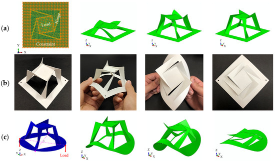
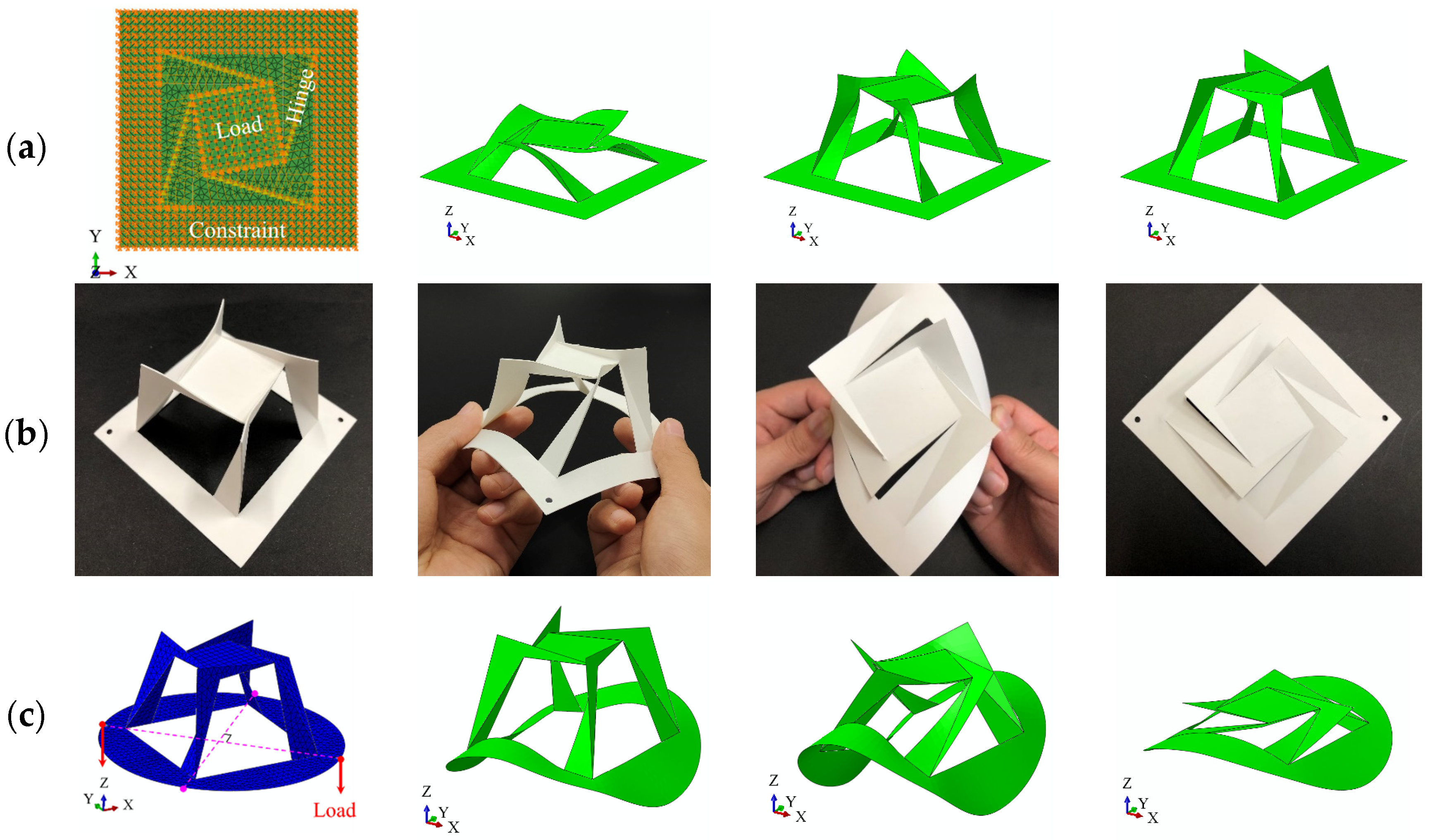
In the top stretch forming motion process of finite element simulation, the vertical displacement load u = 26 mm is applied to the center hub plane to make the configuration move from the plane state to the three-dimensional state. The morphological changes in configuration are shown in Figure 10a; the center hub rotates counterclockwise, the arm and the tab gradually become upright, indicating that the finite element process fits well with the experimental phenomena, and the general recovery is the inverse process of the top stretch forming motion process.
Figure 10.
(a) FEM model of stretching forming; (b) physical model of initiative recovery; (c) FEM model of initiative recovery.
Now, we introduce a new recovery method named arching recovery, which makes the model change from the upright state to the plane state by applying the out-of-plane load. The arching recovery process is shown in Figure 10b. The FEM model is shown in Figure 10c, with the material and geometric parameters the same as before, except that external border b is replaced by external radius r = 35 mm, the out-of-plane displacement load v = 20 mm is applied on the edge of the model, and the displacement Uz of the two points, which are perpendicular to the line of loading point and intersect at the edge of the model, are constrained.
The arm gradually changes from an upright state to a flat state, driving the vertical displacement of the tab to decrease. The center hub connected with the tab rotates and decreases simultaneously, and the creases disappear from the second picture to the third picture of Figure 10c, which indicates that the model completes the morphological transformation. Finally, the model is changed to a plane state with the load release.
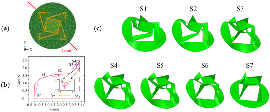
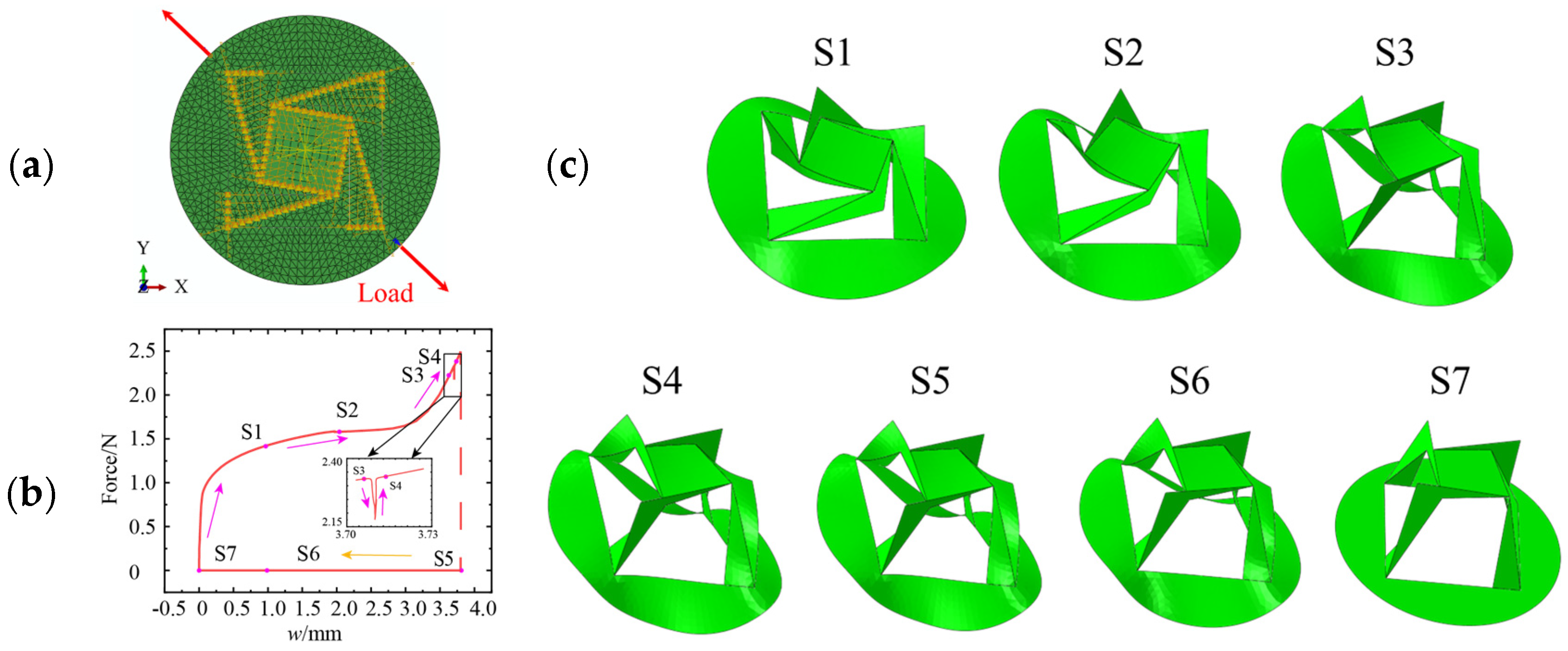
Diagonal stretch forming, as an initiative forming method, can realize modular construction and arrangement design. The FEM model of diagonal stretch forming is shown in Figure 11a. A displacement load w = 3.8 mm is applied along the loading direction and constrains the displacement Uz of the loading point. The relationship between force and displacement is shown in Figure 11b, and the morphological changes are shown in Figure 11c.
Figure 11.
(a) FEM model of diagonal stretch forming; (b) force–displacement curve in diagonal stretch forming process; (c) morphological changes in diagonal stretch forming process.
In the diagonal stretch forming motion process of finite element simulation, the arm and center hub rise and rotate with the loading increase, and the external radius panel buckles. While the morphology switches from S3 to S4, there is a significant mutation at the force–displacement curve, indicating that the model realizes the entire transformation from the plane state to a three-dimensional state forming with a steady state. The creases between the central hub and the tab, as well as the tab and the arm, are obviously produced. At this moment, the displacement load increases from 3.70 mm to 3.73 mm, which shows that the configuration can form with a diagonal stretch load when the load is greater than 3.73 mm. While the load was released, the morphology changed from S5 to S7, the external radius panel deformed freely, and the finial became flattened. The difference between diagonal stretch forming and top stretching forming is the position of the load and whether the external panel has buckling deformation. In the loading process, the load displacement curve of the diagonal stretch forming is in good agreement with the force displacement curve of the experiment.
5. Discussion
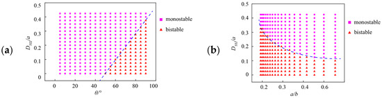
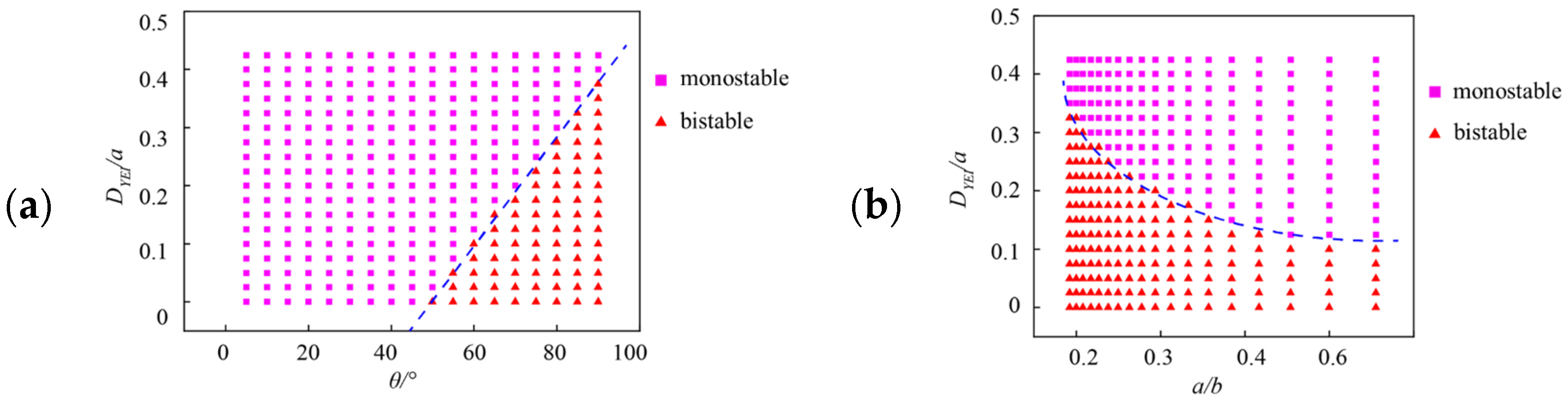
In the previous section, the single variable method was used to analyze the bistable state of the model. If it is a multi-variable, what will be the bistable characteristics of the configuration? Next, we expand the calculated samples and use dimensionless quantities for variable analysis to obtain the bistable parameter discrimination diagram of the configuration, as shown in Figure 12. It can be seen that the value of DYEI/a and a/b become smaller, θ becomes larger, and the configuration tends to a bistable characteristic.
Figure 12.
The bistable characteristic under different parameters: (a) DYEI/a-θ; (b) DYEI/a-a/b.
Therefore, compared with the traditional RES configuration, the designed configuration has critical boundaries between monostable and bistable, which can provide a design basis of reconfigurable system. Moreover, the designed configuration can be recovered by induced buckling, which is a new active shape control.
Finally, the shape changes in all the tested models in the forming process and the recovery process are consistent with the corresponding finite element simulation results, which shows that the finite element results have good reliability.
6. Conclusions
This research mainly aimed at the bistable characteristic of the RES configuration. The geometric, experimental, and finite element analyses were investigated, and the conclusion is that the designed configuration has bistable characteristics, it can be formed and recovered actively, and the finite element simulation and experimental results are consistent.
Author Contributions
Conceptualization, N.P.; Methodology, N.P.; Software, S.L.; Investigation, S.L. and N.P.; Data curation, N.P.; Writing—original draft, S.L.; Writing—review & editing, S.L.; Supervision, J.F. and J.C.; Funding acquisition, J.F. and J.C. All authors have read and agreed to the published version of the manuscript.
Funding
This paper was supported by the National Natural Science Foundation of China (NOs. 52478306, 52478145).
Data Availability Statement
The data presented in this study are available on request from the corresponding author on reasonable request.
Conflicts of Interest
The authors declare no conflict of interest.
References
- Turco, E.; Barchiesi, E.; Dell Isola, F. The long and winding road that leads to homogenisation of Kresling origami. Int. J. Non-Linear Mech. 2024, 163, 104756. [Google Scholar] [CrossRef] [Scilit]
- Zhou, Y.; Zhang, Y.; Feng, J.; Cai, J. Numerical study of the hysteretic behavior of energy dissipation braces based on Miura origami. Int. J. Non-Linear Mech. 2023, 157, 104523. [Google Scholar] [CrossRef] [Scilit]
- Fonseca, L.M.; Savi, M.A. Nonlinear dynamics of an autonomous robot with deformable origami wheels. Int. J. Non-Linear Mech. 2020, 125, 103533. [Google Scholar] [CrossRef] [Scilit]
- Cai, J.; Zhong, Q.; Pan, L.; Meloni, M.; Zhang, Q.; Feng, J. Nonlinear wrap-folding of membranes with predefined creases and seams. Int. J. Non-Linear Mech. 2023, 156, 104519. [Google Scholar] [CrossRef] [Scilit]
- Cai, J.; Li, M.; Li, Y.; Ding, Y.; Feng, J. Deployment simulation of a scalable planar gossamer space structure based on Miura-ori pattern. Adv. Space Res. 2021, 67, 3343–3353. [Google Scholar] [CrossRef] [Scilit]
- Zhang, Q.; Wang, X.; Lee, D.S.-H.; Cai, J.; Ren, Z.; Feng, J. Development of kinetic origami canopy using Arc Miura folding patterns. J. Build. Eng. 2021, 43, 103116. [Google Scholar] [CrossRef] [Scilit]
- Zhou, Y.; Zhang, Q.; Cai, J.; Zhang, Y.; Yang, R.; Feng, J. Experimental study of the hysteretic behavior of energy dissipation braces based on Miura origami. Thin-Walled Struct. 2021, 167, 108196. [Google Scholar] [CrossRef] [Scilit]
- Cai, J.; Ren, Z.; Ding, Y.; Deng, X.; Xu, Y.; Feng, J. Deployment simulation of foldable origami membrane structures. Aerosp. Sci. Technol. 2017, 67, 343–353. [Google Scholar] [CrossRef] [Scilit]
- Ye, K.; Ji, J.C.; Fitch, R. Further investigation and experimental study of an origami structure-based quasi-zero-stiffness vibration isolator. Int. J. Non-Linear Mech. 2023, 157, 104554. [Google Scholar] [CrossRef] [Scilit]
- Sun, X.; Lv, Q.; Qian, J.; Xu, J. Vibration isolation platform for large-amplitude-low-frequency excitation by parallel-stack-assembly design of Miura origamis. Int. J. Non-Linear Mech. 2024, 166, 104831. [Google Scholar] [CrossRef] [Scilit]
- Babaee, S.; Shi, Y.; Abbasalizadeh, S.; Tamang, S.; Hess, K.; Collins, J.E.; Ishida, K.; Lopes, A.; Williams, M.; Albaghdadi, M.; et al. Kirigami-inspired stents for sustained local delivery of therapeutics. Nat. Mater. 2021, 20, 1085–1092. [Google Scholar] [CrossRef] [Scilit]
- Wang, Y.; Huang, X.; Zhang, X. Ultrarobust, tough and highly stretchable self-healing materials based on cartilage-inspired noncovalent assembly nanostructure. Nat. Commun. 2021, 12, 1291. [Google Scholar] [CrossRef] [Scilit]
- Knappe, G.A.; Wamhoff, E.; Bathe, M. Functionalizing DNA origami to investigate and interact with biological systems. Nat. Rev. Mater. 2023, 8, 123–138. [Google Scholar] [CrossRef] [Scilit]
- Meloni, M.; Cai, J.; Zhang, Q.; Sang-Hoon Lee, D.; Li, M.; Ma, R.; Parashkevov, T.E.; Feng, J. Engineering origami: A comprehensive review of recent applications, design methods, and tools. Adv. Sci. 2021, 8, 2000636. [Google Scholar] [CrossRef] [Scilit]
- Lamoureux, A.; Lee, K.; Shlian, M.; Forrest, S.R.; Shtein, M. Dynamic kirigami structures for integrated solar tracking. Nat. Commun. 2015, 6, 8092. [Google Scholar] [CrossRef] [Scilit]
- Zhang, X.; Gao, C.; Chen, W.; Yang, T.; Yang, S.; Fang, G. Design of thick-panel origami-inspired deployable protective shields for spacecraft. Thin-Walled Struct. 2024, 202, 112069. [Google Scholar] [CrossRef] [Scilit]
- Ze, Q.; Wu, S.; Nishikawa, J.; Dai, J.; Sun, Y.; Leanza, S.; Zemelka, C.; Novelino, L.S.; Paulino, G.H.; Zhao, R.R. Soft robotic origami crawler. Sci. Adv. 2022, 8, eabm7834. [Google Scholar] [CrossRef] [Scilit]
- Han, M.; Wang, H.; Yang, Y.; Liang, C.; Bai, W.; Yan, Z.; Li, H.; Xue, Y.; Wang, X.; Akar, B.; et al. Three-dimensional piezoelectric polymer microsystems for vibrational energy harvesting, robotic interfaces and biomedical implants. Nat. Electron. 2019, 2, 26–35. [Google Scholar] [CrossRef] [Scilit]
- Felton, S.; Tolley, M.; Demaine, E.; Rus, D.; Wood, R. Applied origami: A method for building self-folding machines. Science 2014, 345, 644–646. [Google Scholar] [CrossRef] [Scilit] [PubMed]
- Ye, H.; Liu, Q.; Cheng, J.; Li, H.; Jian, B.; Wang, R.; Sun, Z.; Lu, Y.; Ge, Q. Multimaterial 3D printed self-locking thick-panel origami metamaterials. Nat. Commun. 2023, 14, 1607. [Google Scholar] [CrossRef] [Scilit] [PubMed]
- Liu, T.; Deng, R.; Jin, L.; Cai, J. Rate-dependent and delayed snap-through behaviors of viscoelastic metamaterials. Int. J. Mech. Sci. 2024, 283, 109664. [Google Scholar] [CrossRef] [Scilit]
- Cai, J.; Akbarzadeh, A. Hierarchical kirigami-inspired graphene and carbon nanotube metamaterials: Tunability of thermo-mechanic properties. Mater. Des. 2021, 206, 109811. [Google Scholar] [CrossRef] [Scilit]
- Liu, W.; Jiang, H.; Chen, Y. 3D Programmable metamaterials based on reconfigurable mechanism modules. Adv. Funct. Mater. 2022, 32, 2109865. [Google Scholar] [CrossRef] [Scilit]
- Lu, R.; Zhang, Q.; Zhang, H.; Meloni, M.; Feng, J.; Cai, J. Quasi-static crushing response of a novel triaxial isotropy mechanical metamaterial with dual-platform property. Thin-Walled Struct. 2025, 206, 112630. [Google Scholar] [CrossRef] [Scilit]
- Wang, Y.; Zhang, Q.; Pan, N.; Xu, Y.; Lu, D.; Cai, J.; Feng, J. Mechanical properties of hoberman radially retractable roof structures. Thin-Walled Struct. 2024, 203, 112176. [Google Scholar] [CrossRef] [Scilit]
- Wang, Y.; Zhang, Q.; Jiang, C.; Kueh, A.B.; Feng, J.; Cai, J. Packing optimization and design of the deployable parabolic rigid antenna based on origami. Adv. Space Res. 2024, 73, 6226–6240. [Google Scholar] [CrossRef] [Scilit]
- Zhang, Q.; Shi, C.; Zhang, X.; Feng, J.; Cai, J. Interleaved assembly and compressive behavior of non-Euclidean origami structures. Thin-Walled Struct. 2026, 218, 113994. [Google Scholar] [CrossRef] [Scilit]
- Choi, G.P.T.; Dudte, L.H.; Mahadevan, L. Programming shape using kirigami tessellations. Nat. Mater. 2019, 18, 999–1004. [Google Scholar] [CrossRef] [Scilit] [PubMed]
- Zhang, X.; Medina, L.; Cai, H.; Aksyuk, V.; Espinosa, H.D.; Lopez, D. Kirigami engineering-nanoscale structures exhibiting a range of controllable 3D configurations. Adv. Mater. 2021, 33, 2005275. [Google Scholar] [CrossRef] [Scilit]
- Shi, C.; Zhang, Q.; Feng, J.; Kim, S.; Cai, J. Tensile self-locking behavior of reconfigurable origami structure. Eng. Struct. 2025, 335, 120362. [Google Scholar] [CrossRef] [Scilit]
- Deng, H.; Sattari, K.; Xie, Y.; Liao, P.; Yan, Z.; Lin, J. Laser reprogramming magnetic anisotropy in soft composites for reconfigurable 3D shaping. Nat. Commun. 2020, 11, 6325. [Google Scholar] [CrossRef] [Scilit]
- Yoshinobu, M. Rotational Erection System (RES): Origami extended with cuts. In Origami 6: Proceedings of the Sixth International Meeting on Origami Science, Mathematics, and Education; AMS: Providence, RI, USA, 2015; Volume 2, pp. 537–544. [Google Scholar]
- Lee, S.; Lee, M.; Lim, S. Frequency reconfigurable antenna actuated by three-storey tower kirigami. Extrem. Mech. Lett. 2020, 39, 100833. [Google Scholar] [CrossRef] [Scilit]
- Duan, Y.; Li, R.; Tie, Y.; Wang, T. Research on the cushioning and springback properties of rotational erection kirigami structure. Thin-Walled Struct. 2025, 215, 113455. [Google Scholar] [CrossRef] [Scilit]
- Yoneda, T.; Miyamoto, Y.; Wada, H. Structure, design, and mechanics of a pop-up origami with cuts. Phys. Rev. Appl. 2022, 17, l021004. [Google Scholar] [CrossRef] [Scilit]
- Zhang, Q.; Pan, N.; Liu, S.; Feng, J.; Cai, J. Self-locking Kirigami surfaces via controlled stretching. Commun. Eng. 2024, 3, 26–29. [Google Scholar] [CrossRef] [Scilit]
- Cheng, X.; Zhang, Y. Micro/Nanoscale 3D assembly by rolling, folding, curving, and buckling approaches. Adv. Mater. 2019, 31, 1901895. [Google Scholar] [CrossRef] [Scilit]
- Hunt, G.W.; Ario, I. Twist buckling and the foldable cylinder: An exercise in origami. Int. J. Non-Linear Mech. 2005, 40, 833–843. [Google Scholar] [CrossRef] [Scilit]
- Rajak, P.; Wang, B.; Nomura, K.-I.; Luo, Y.; Nakano, A.; Kalia, R.; Vashishta, P. Autonomous reinforcement learning agent for stretchable kirigami design of 2D materials. npj Comput. Mater. 2021, 7, 102. [Google Scholar] [CrossRef] [Scilit]
- Yan, Z.; Zhang, F.; Wang, J.; Liu, F.; Guo, X.; Nan, K.; Lin, Q.; Gao, M.; Xiao, D.; Shi, Y.; et al. Controlled mechanical buckling for origami-inspired construction of 3d microstructures in advanced materials. Adv. Funct. Mater. 2016, 26, 2629–2639. [Google Scholar] [CrossRef] [Scilit] [PubMed]
- Zhang, Y.; Yan, Z.; Nan, K.; Xiao, D.; Liu, Y.; Luan, H.; Fu, H.; Wang, X.; Yang, Q.; Wang, J.; et al. A mechanically driven form of Kirigami as a route to 3D mesostructures in micro/nanomembranes. Proc. Natl. Acad. Sci. USA 2015, 112, 11757–11764. [Google Scholar] [CrossRef] [Scilit]
- Chen, S.; Liu, Z.; Du, H.; Tang, C.; Ji, C.-Y.; Quan, B.; Pan, R.; Yang, L.; Li, X.; Gu, C.; et al. Electromechanically reconfigurable optical nano-kirigami. Nat. Commun. 2021, 12, 1299. [Google Scholar] [CrossRef] [Scilit]
- Jin, B.; Liu, J.; Shi, Y.; Chen, G.; Zhao, Q.; Yang, S. Solvent-assisted 4D programming and reprogramming of liquid crystalline organogels. Adv. Mater. 2022, 34, 2107855. [Google Scholar] [CrossRef] [Scilit] [PubMed]
- Li, X.; Huang, H.; Yan, P.; Wang, W. Design and analysis of rigid-elastic coupling origami flashers with bistable characteristics. Int. J. Mech. Sci. 2024, 282, 109602. [Google Scholar] [CrossRef] [Scilit]
- Masana, R.; Daqaq, M.F. Equilibria and bifurcations of a foldable paper-based spring inspired by Kresling-pattern origami. Phys. Rev. E 2019, 100, 63001. [Google Scholar] [CrossRef] [Scilit] [PubMed]
- Sharma, H.; Chaudhary, A.; Upadhyay, S.H. Experimental verification of the bistable behavior of conical Kresling origami. Thin-Walled Struct. 2023, 190, 110980. [Google Scholar] [CrossRef] [Scilit]
- Zhang, L.; Pan, F.; Ma, Y.; Yang, K.; Guo, S.; Chen, Y. Bistable reconfigurable origami metamaterials with high load-bearing and low state-switching forces. Extrem. Mech. Lett. 2023, 63, 102064. [Google Scholar] [CrossRef] [Scilit]
- Masana, R.; Khazaaleh, S.; Alhussein, H.; Crespo, R.S.; Daqaq, M.F. An origami-inspired dynamically actuated binary switch. Appl. Phys. Lett. 2020, 117, 081901. [Google Scholar] [CrossRef] [Scilit]
- Pagano, A.; Yan, T.; Chien, B.; Wissa, A.; Tawfick, S. A crawling robot driven by multi-stable origami. Smart Mater. Struct. 2017, 26, 94007. [Google Scholar] [CrossRef] [Scilit]
- Ishida, S.; Uchida, H.; Shimosaka, H.; Hagiwara, I. Design and numerical analysis of vibration isolators with quasi-zero-stiffness characteristics using bistable foldable structures. J. Vib. Acoust. 2017, 139, 031015. [Google Scholar] [CrossRef] [Scilit]
- De Focatiis, D.S.A.; Guest, S.D. Deployable membranes designed from folding tree leaves. Philos. Trans. A Math. Phys. Eng. Sci. 2002, 360, 227–238. [Google Scholar] [CrossRef] [Scilit]
- Cai, J.; Deng, X.; Zhou, Y.; Feng, J.; Tu, Y. Bistable Behavior of the Cylindrical Origami Structure with Kresling Pattern. J. Mech. Des. 2015, 137, 061406. [Google Scholar] [CrossRef] [Scilit]
- Zhai, Z.; Wang, Y.; Jiang, H. Origami-inspired, on-demand deployable and collapsible mechanical metamaterials with tunable stiffness. Proc. Natl. Acad. Sci. USA 2018, 115, 2032–2037. [Google Scholar] [CrossRef] [Scilit] [PubMed]
Disclaimer/Publisher’s Note: The statements, opinions and data contained in all publications are solely those of the individual author(s) and contributor(s) and not of MDPI and/or the editor(s). MDPI and/or the editor(s) disclaim responsibility for any injury to people or property resulting from any ideas, methods, instructions or products referred to in the content. |
© 2026 by the authors. Licensee MDPI, Basel, Switzerland. This article is an open access article distributed under the terms and conditions of the Creative Commons Attribution (CC BY) license.