


Abstract
The building sector accounts for a large percentage of global greenhouse gas emissions, largely from the embodied carbon in common building materials like concrete and steel. Embodied carbon (EC) refers to the greenhouse gases released during the manufacturing, transportation, installation, maintenance, and disposal of building materials. Although growing in popularity, mass timber is still not nearly as common as other building materials. During the early building design stages, engineers often do not have the time or resources to holistically optimize material selection; consequently, concrete and steel remain the materials of choice. This research focused on the development of a fully automated parametric design tool, APDT, to showcase the viability of evaluating and optimizing mass timber in building construction. The APDT was developed using Autodesk’s Revit 2022 and the visual-based programming tool housed within Revit: Dynamo. The automated designer uses parametric inputs of a building, including size, number of stories, and loading, to create a model of a mass timber building with designed glulam columns and beams and cross-laminated timber floor panels. The designer calculates overall material quantities, which are then used to determine the building’s overall embodied carbon impact. Discussed herein is the development of a building design tool that highlights the benefits of optimized mass timber using existing software and databases. The tool allows the designer to expediently provide an estimate of the amount of material and embodied carbon values, thereby making it easier to consider mass timber when determining the structural system at the infancy stage of the project. The methodology outlined herein provides a replicable methodology for creating an APDT that bridges a critical gap in early-stage design, enabling rapid embodied carbon comparisons and fostering consideration of mass timber as a viable low-carbon alternative.
1. Introduction
Material selection is an essential aspect of any structure and is typically constrained by the goals of the project. The materials a structure is built with will define its physical properties, like strength and durability. A variety of factors such as the building’s intended purpose, location, size, height, and the goals of the developer influence the materials that are chosen for the structural system of a building. Until recently, the carbon footprint and sustainability of materials were not often considered. The motivation behind this project was to understand how different materials affect a building’s overall carbon footprint and to determine the feasibility of using mass timber as the primary structural system. An understanding of different materials and their carbon footprint properties was gained through the literature review. This review also provided a foundation of knowledge on current embodied carbon reduction strategies and advances in BIM and parametric LCA optimization. The goal of this project was to use the knowledge gained from this review to find ways to make sustainable, low-carbon building choices more attainable. This goal led to the development of a fully automated parametric mass timber designer. The targeted capabilities of this tool include the following:
- Parametric inputs for building characteristics such as bay size, number of stories, and loading;
- Ability to create a variable building grid;
- Ability to accurately design glulam columns;
- Ability to accurately design glulam beams;
- Ability to select CLT floor panel thickness;
- Creation of a 3D model with the designed structural elements;
- Material takeoff calculation;
- Embodied carbon calculation.
The main goal of this APDT is to show how commercially available software can be used to efficiently compare mass timber to other materials for building design in terms of embodied carbon. Such a tool can place mass timber at the forefront during conversations on building materials. As demonstrated herein, existing software enables easy programming and provides a mechanism for determining material volumes and their associated carbon costs, making this tool extremely useful for assessing the viability of mass timber as the primary structural system.
The building sector accounts for approximately one-third of global greenhouse gas emissions (United Nations, 2024) [1]. The materials used to construct buildings account for most of their embodied carbon. Concrete and steel, two of the best building materials, also have incredibly high carbon footprints. Both materials, especially concrete, emit large amounts of carbon during their manufacturing process [2].
Carbon emissions from buildings are classified into two designations: operational carbon and embodied carbon. Operational carbon is the carbon that is released during the building’s active life of use. Examples of operational carbon include emissions from heating or cooling, electricity use, and water use. The Carbon Leadership Forum defines embodied carbon in the building industry as “the greenhouse gas emission arising from the manufacturing, transportation, installation, maintenance, and disposal of building materials” [3].
Multiple studies and literature reviews have been conducted to address embodied carbon reduction strategies that are already working, as well as to propose new techniques that may help on their own or that can be used in conjunction with existing strategies to provide meaningful reductions in embodied carbon. A study performed by Hu explored existing publications and identified 19 mitigation strategies, which were put into four categories: design optimization, material optimization, construction optimization, and infrastructure optimization [4]. Some of the strategies outlined include limiting building sizes and optimizing layouts, using low-carbon and alternative materials, reusing and recycling materials, and repurposing existing buildings instead of building new. A similar study had been conducted by Pomponi and Moncaster in 2016 [5] and resulted in a list of 17 embodied carbon mitigation strategies. Some of the strategies outlined in this research included increasing the use of local materials, improving policy and regulation, reducing, reusing, and recovering carbon-intensive materials, and developing practice guidelines for wider use of low-carbon materials [5].
Other research has shown that carbon sequestration and offsets [6], carbon accounting using building information management (BIM) technology [7], and life-cycle analysis [8] can all be effective in reducing and managing a building’s carbon footprint. Significant advances in BIM and LCA software have occurred that aid in identifying the environmental impact of material selection. Recent work has moved beyond manual LCA toward parametric LCA and optimization loops (generative design/structural optimization) that search for environmentally sensitive design solutions.
Al-Obaidy et al. [9] utilized parametric modeling (21 alternate designs, 630 iterations) with LCA software and demonstrated how parametric variation in structural systems and materials can significantly reduce embodied carbon. “The focus of the whole life cycle assessment was mainly on carbon neutrality. Results indicate that using local bio-sourced materials, including timber, can remarkably reduce buildings’ environmental impact” [9].
Mohamed et al. [10] proposed a framework/tool for automating EC calculations within BIM. Their approach utilized literature reviews and “hands-on exploration” to create a BIM-integrated LCA tool intended to provide information during the design process to create low-carbon buildings. Within a UK context, the authors developed a Dynamo-based model to automate the LCA process with the hopes of transforming the integration of LCA in the building design process. Ma et al. [11] provides a US case study of a hybrid concrete steel high-rise to highlight how building information modeling (BIM) based life cycle assessment (LCA) in Revit can be used to examine embodied carbon and environmental impacts. The results show that the embodied carbon and environmental impacts of the high-rise building structure are dominated by the impacts of the product stage in the building life cycle, and concrete is the main structural material. It was determined that concrete accounts for 91% of the building structure’s mass and 74% of its life-cycle global warming potential, while steel accounts for 9% of the building structure’s mass and 26% of its global warming potential [11]. An alternative to mass timber was not investigated.
Parece et al. [12] provide a method for automating embodied carbon assessment via classification mapping to support early design decisions. The advantages of the proposed tool include data control, continuous LCA study during the design process, integration with finish maps and quantities, and availability for free use. Parece et al. [13] followed up on this study with a systematic literature review of recent studies to address how BIM-LCA supports decision-making or how decision-making methods can enhance its adoption and use. A total of 115 research articles between 2019 and 2024 were reviewed. Advancements in the integration of BIM and LCA were noted, and limitations and suggested paths forward were provided.
Szalay noted that several European countries are in the process of incorporating whole-life-cycle considerations into building design, and three already have CO2 limits [14]. Furthermore, it was predicted that by 2030, life-cycle assessment would be a mandatory calculation method for new buildings across all European states. A methodology for developing benchmark reference values for the environmental impact of buildings was presented. The methodology proved suitable for estimating the environmental impact of typical buildings and generating embodied carbon reference values. Additionally, the sensitivity of many design variables was highlighted [14].
Huang et al. [15] integrated parametric BIM with multi-objective optimization in order to assess mechanical carbon emissions related to deconstruction. The project highlighted trade-offs between the deconstruction period, efficiency, and mechanical carbon emissions. Mass timber was not investigated.
Keyhani et al. [16] explored the integration of BIM and LCA to improve the assessment of EC in building design. The research compared traditional manual LCA with an automated BIM-LCA approach, utilizing Autodesk Revit and Python 3.12 programming for enhanced accuracy and efficiency. Results of a case study highlighted that the automated approach significantly reduced assessment time while maintaining nearly the same accuracy. This automation approach allowed for expedited EC assessments early in the design process and optimized material choices to reduce carbon emissions [16].
Bacheva and Grau [17] examined how embodied carbon and life cycle coverage are addressed across many disciplines and stakeholders. A sequenced framework of seven interlinked barriers, ranging from data availability and methodological standardization to innovation diffusion and cost integration, was proposed. The study identified geographic concentration, limited social sustainability integration, and fragmented stakeholder involvement as major current limitations. Ferreira et al. [18] highlighted an existing gap in the optimization of LCA design. A BIM plug-in was used in conjunction with benchmark studies from the literature to evaluate numerous environmental impacts in real-time.
Huang et al. [19] provide an excellent review of the literature related to BIM-based embodied carbon evaluation during the building’s early design stage. The review concluded by noting many research gaps and limitations in this field. Zhang et al. [20] present an overview, within the U.S. context, of the methodologies used to assess EC emissions at each life-cycle stage of building design. An excellent review of the LCA tools available is presented, including a summary of recent case studies on embodied carbon assessment and reduction [21,22,23,24,25,26,27]. Additionally, an overview of international standards and building codes related to the embodied carbon of buildings is provided. The report concludes by highlighting future research needs in LCA practice, methodology, and applications [20].
Advancements in structural design software and BIM have made it relatively easy to model and design structures using a computer. These technologies allow for quicker design of more complex structures that, at times, may not even be possible to do entirely by hand. However, there is a significant gap between what can be achieved with computer software and concrete and steel and what can be achieved with wood and mass timber. There is a lack of tools that designers can utilize to receive early guidance on design decisions and to compare possibilities/layouts of a mass timber structure.
Leonard and Solnosky [28] used Grasshopper/Rhino in conjunction with a spreadsheet-based model with a parametric modeling approach to develop a dataset to assist designers’ decision-making in the early stages of a mass timber project. The goal of the tool was to combine structural design with embodied carbon data, with a wide range of variables and floor systems to provide designers with the best information to guide their decisions. A parametric model was used to investigate multiple floor systems and configurations for both structural design and embodied carbon goals. Systems with rectangular, regularly spaced bays were investigated with timber floors, timber girders, timber beams, steel girders, steel beams, and timber-concrete composite floors. Other variables included in this study were bay length, framing material, number of infill beams, fireproofing, and wood species [28].
Custom Python code was created to size structural members within each floor system using Allowable Stress Design. These code components select an initial element size from a database based on initial load assumptions, then resize it as needed until it meets the criteria demanded by the applicable loading. This model was currently programmed to select the lightest elements with the lowest EC elements (2023) [28]. Embodied carbon data for the structural materials were obtained from a database focusing on stages A1–A3 of the building’s life. For nonstructural elements, EC data was obtained from publicly available EPDs. Once the total volume of materials was determined, the embodied carbon totals were calculated by multiplying the material take-off values by their corresponding EPDs [28].
This research demonstrates that parametric design for mass timber is possible in a variety of ways. The research outcome appears to be a promising tool to guide designers in the early stages of projects on both optimum floor systems and different mass timber possibilities, as well as providing valuable embodied carbon data early in the project.
2. Methodology and Design Tools
The development of the model described herein was aided by multiple tools. Revit was used to visualize the 3D model. Revit also houses Dynamo, a visual-based coding language used to create the script that executes the design and modeling. Finally, Microsoft Excel was used to create the mass timber section databases necessary to design the beams, columns, and floor panels.
Revit is a building information modeling (BIM) software product by Autodesk Inc. BIM software is incredibly useful within the structural engineering industry. Software like Revit is used to create 3D models and build 2D drawings, and plan sets that illustrate all aspects of the project, including architectural details, MEP information, and structural/construction details. This project primarily uses the Revit 3D viewer to visualize the models designed by the Dynamo script (Autodesk® Revit 2022) [29].
Dynamo is a visual-based programming application that utilizes nodes connected together to execute functions. Dynamo has an expansive library of nodes and functions that can be used to automate tasks, process data, create geometry, and more. Dynamo can be useful to anyone who regularly uses Revit due to its powerful ability to add customized functionality to any Revit model. Dynamo also allows a user to create their own functions using Python coding. The automated designer created in this project is powered entirely by Dynamo and sections of Python code (Autodesk® Dynamo 2022) [30]. Microsoft Excel was utilized to create section databases for the Dynamo script to read when designing the structural elements for the model (Microsoft® Excel® for Microsoft 365 MSO (Version 2403 Build 16.0.17425.20124)) [31].
3. Script Setup and Modeling
3.1. Introduction to the Script Process
The scripting process involves adding and connecting Dynamo nodes to execute functions. The development of the script began with the creation of mass timber section databases in Excel. The script was built starting with the parametric inputs and the initial geometry of the building, and then the sections of the script responsible for modeling and designing the structural elements were added. Finally, the material takeoff and embodied carbon calculations were programmed. The script consists of over 430 individual Dynamo nodes. Each node executes a small function such as adding two numbers, placing a point, or translating geometry. Many nodes store data as lists, from which data points can be extracted, combined, or rearranged to create a desired result. Within the script, nodes are grouped together to perform larger functions such as the creation of gridlines, building the overall geometry of beams, columns, and floors, or calculating loads and embodied carbon values.
3.2. Section Database
The first element of the script developed was the mass timber section database built in Excel. These databases are based on data from Nordic Structures, a mass timber manufacturer based in Canada [32,33]. For their glulam columns, Nordic tabulates allowable compressive loads based on column dimensions and height, like the AISC Steel Manual Table 4-1 [34]. They also developed tables showing allowable bending moments for different sizes of glulam beams, as well as a table that governs the selection of CLT floor panels based on span and floor loading. The allowable capacities are also adjusted for 30, 60, 90, and 120 min fire ratings. Fire rating is an important part of mass timber design. In the event of a fire, exposed mass timber elements will form a char layer over time. This char layer serves as insulation and protection for the rest of the elements’ cross-section. It is imperative that exposed mass timber elements are designed correctly for the event of a fire. The information from these tables was rearranged and manually entered into Excel sheets so it could be efficiently integrated into the script. These tables were a valuable resource in the creation of the script because they allowed the script to turn the input loading data into real, adequately designed sections.
3.3. Elements of the Script
The starting point for this script is the parametric input options. The building characteristic inputs include the number of bays in both directions, the bay size in both directions, the story height/column length, and the number of stories. The load inputs include a live and dead load for both the floors and the roof, as well as the required fire rating. There are also two inputs for the embodied carbon data of glulam and CLT. These inputs are the basis for everything the script does and are what make it a parametric model.
3.4. Parametric Inputs
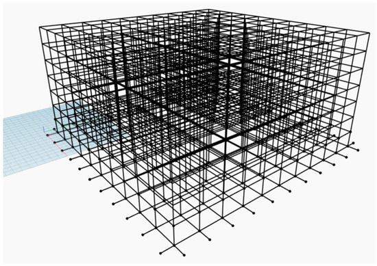
The first section of the script is based on the parameters of bay size and the total number of bays in each direction. This is one of the most essential parts of the script, as it is the foundation for the rest of the model’s geometry. The initial input for the number of bays is converted to points spaced according to the bay size. The number of bays is an N-1 parameter. For example, an input of six bays with a size of ten meters will create six points spaced at ten meters, which creates five ten-meter bays. The number and size of bays can be varied in both directions to allow for different building configurations. An additional set of points is also created directly across from these initial points. These points are connected with lines which ultimately form the grid, as shown in Figure 1. The gridlines also feature a setback for ease of viewing and consistency with typical modeling guidelines. The points that extend beyond the edges are not relevant to the structure.
Figure 1.
Grid lines used for column and beam layout.
The geometry for the beams, columns, and floors is built off the gridlines. The corner points of the grid generate a polygon. This polygon creates a rectangular outline of the floor, visually identical to the edge of the grid but functionally different. This polygon is translated vertically to create any number of floors. The geometry of the polygon is used to generate the floor within the 3D model. The horizontal and vertical gridlines become the beams, and the entire geometry is translated vertically based on the parametric input of story height. The gridline intersection points are connected with lines, which become the columns in the 3D model.
3.5. Design of Structural Elements
With all geometry established, the groundwork for the model is complete. The design of the structural members occurs in the following sections of the script. As previously stated, databases utilizing information from Nordic Structures were created to establish a robust section database of columns, beams, and floor panels (Nordic Structures, 2022) [32].
The script reads the database and turns it into a list that can function like the other datasets in the script. Each structural element is designed separately using a group of nodes and its respective section database. For the beams, span length, maximum moment, and required fire rating are considered. The span length and fire rating are derived from initial parametric inputs, and the maximum moment is calculated using the tributary width of the beam and the dead and live loads. The beam database is set up with rows for beam width, depth, fire rating, and moment capacity. It is also sorted by lowest to highest cross-sectional area to ensure the lightest, most efficient section is selected. At this point, Dynamo had limited options for efficiently searching the database for the correct section. Python coding was used to expand the capabilities of the Dynamo script. Using the Python programming language to code for loops enabled the return of the correct section. The Python script node is where the Python code is contained and uses inputs from Dynamo nodes in the code.
These loops search the database for a beam width and depth that exceeds the required moment and has a fire rating that at least matches the required. The design of glulam beams also involves the calculation of a CV volume factor. This factor, a function of the beam’s length, width, and depth, reduces the beam’s moment capacity. The inclusion of this factor involved a more complicated Python loop that can calculate CV for each beam size and find a beam with an adjusted capacity that exceeds the moment demand. If the loop cannot find a section that has adequate moment capacity and fire rating, it will return the string “No suitable beam found”.
The design of the columns is like the design of the beams but without the addition of the volume factor. Glulam columns do have applicable reduction factors, but these are built into the design table values. The column database consists of rows for column length, fire rating, width, depth, and allowable compressive load. A Python loop was once again required to effectively parse the database for the correct section. The column loop searches for a column size that has the correct column length and fire rating and exceeds the required compressive load. If the loop cannot find a section with enough capacity, it will return the string “inadequate column strength”. This calculation is performed for corner, edge, and interior columns.
The floor panel design also uses a Python loop with a database that was set up slightly differently. The CLT tables from Nordic were organized by dead and live load, panel span, and fire rating. These tables also consider a live-load deflection limit of L/360 and a total-load deflection limit of L/240. The floor panel design loop takes the live load, dead load, panel span, and fire rating and determines the correct CLT layup/number of plays.
3.6. Three-Dimensional Modeling in Revit
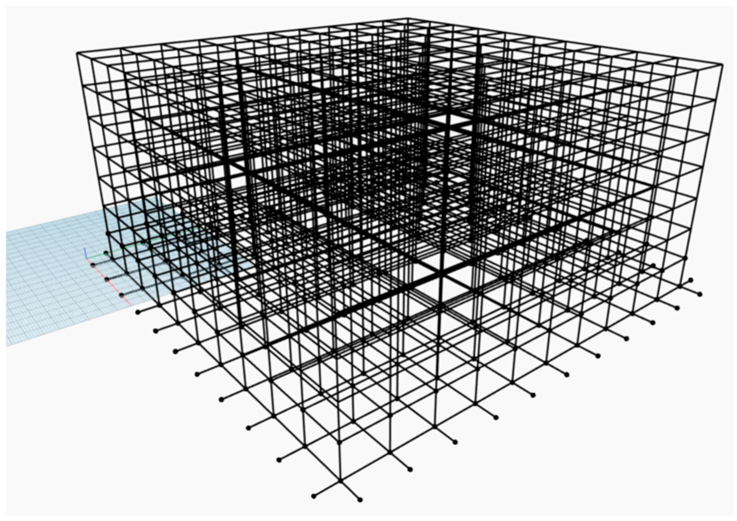
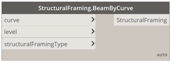
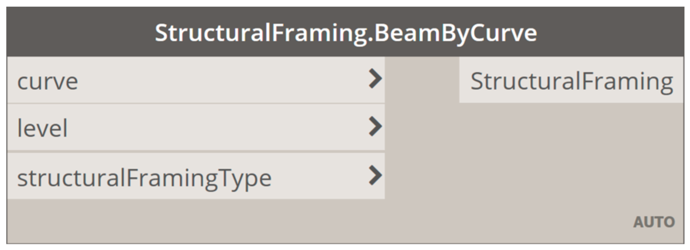
The design portion of the script is a powerful tool and can provide all the necessary results based on the parametric inputs, but a 3D model makes visualizing the building much easier. The Dynamo script builds a wireframe model of the grid and geometry, shown in Figure 2. The StructuralFraming.BeamByCurve nodes, presented in Figure 3, convert these lines into beams and columns, and the floor by outline node converts the polygonal outline into a CLT floor.
Figure 2.
Wire frame three-dimensional model.
Figure 3.
StructuralFraming.BeamByCurve node.
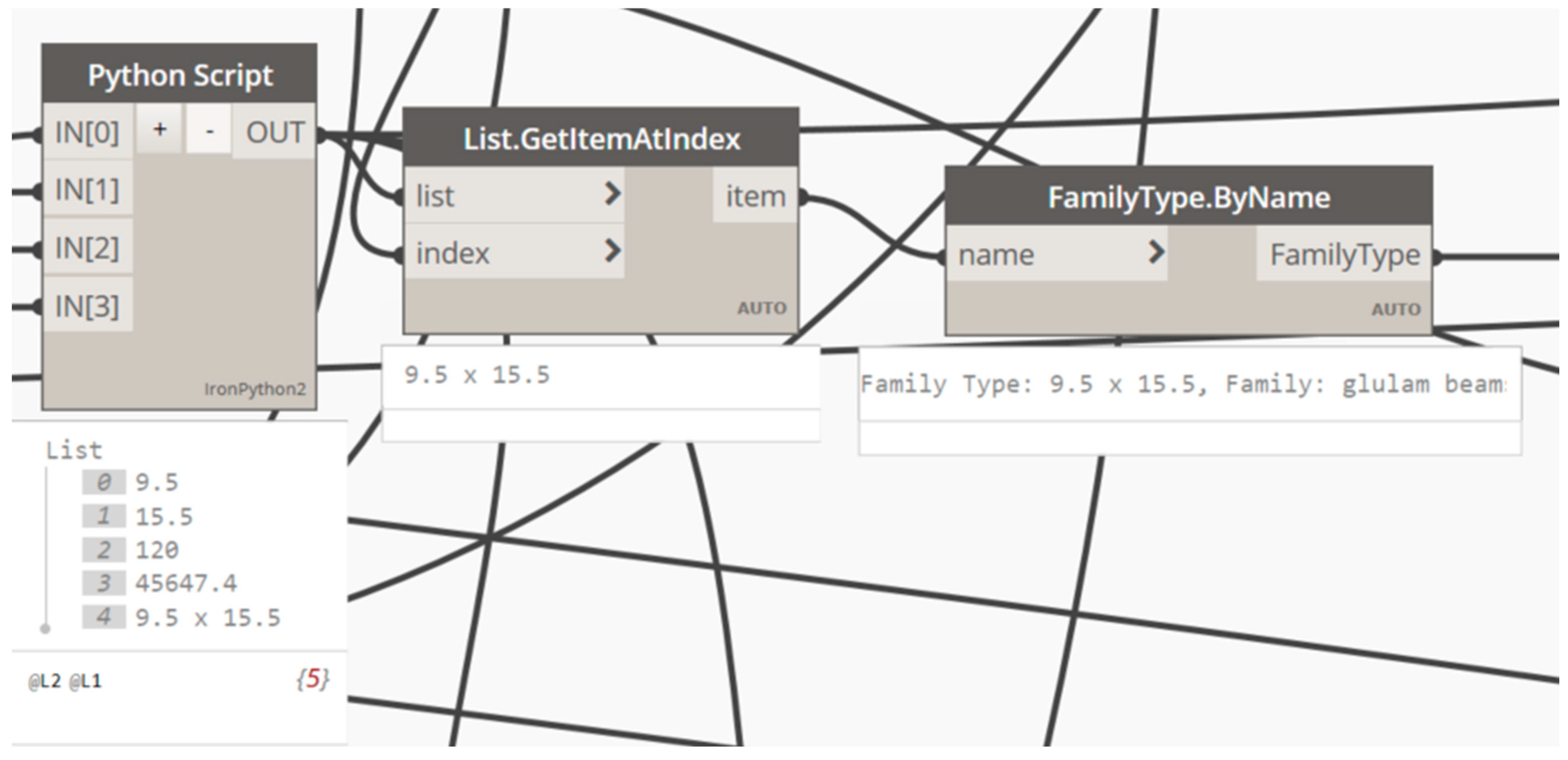
An important part in the development of the script was converting the design results from the Python loops into an input that the structural framing by curve node could use to place the structural elements in the model. Figure 4 demonstrates the solution to this problem. The outputs from the Python script are presented in a list and the List.GetItemAtIndex node can take a single item from the list, in this case, the determined beam/column dimensions. Then, with the dimensions, the FamilyType.ByName node converts this piece of data into an item from a Revit Family. A Revit Family is simply a group of objects that Revit recognizes and can use in models. The families for the beams and columns were developed in the Revit family editor. This tool allows a user to set up an initial geometry with variable dimensions and add as many objects as needed with their required dimensions. The established families create an input that the structural framing by curve node can use to place a beam or column in the model.
Figure 4.
Nodes converting Python outputs into Revit family data.
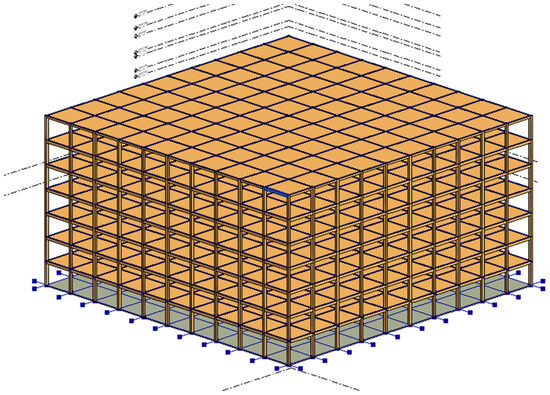
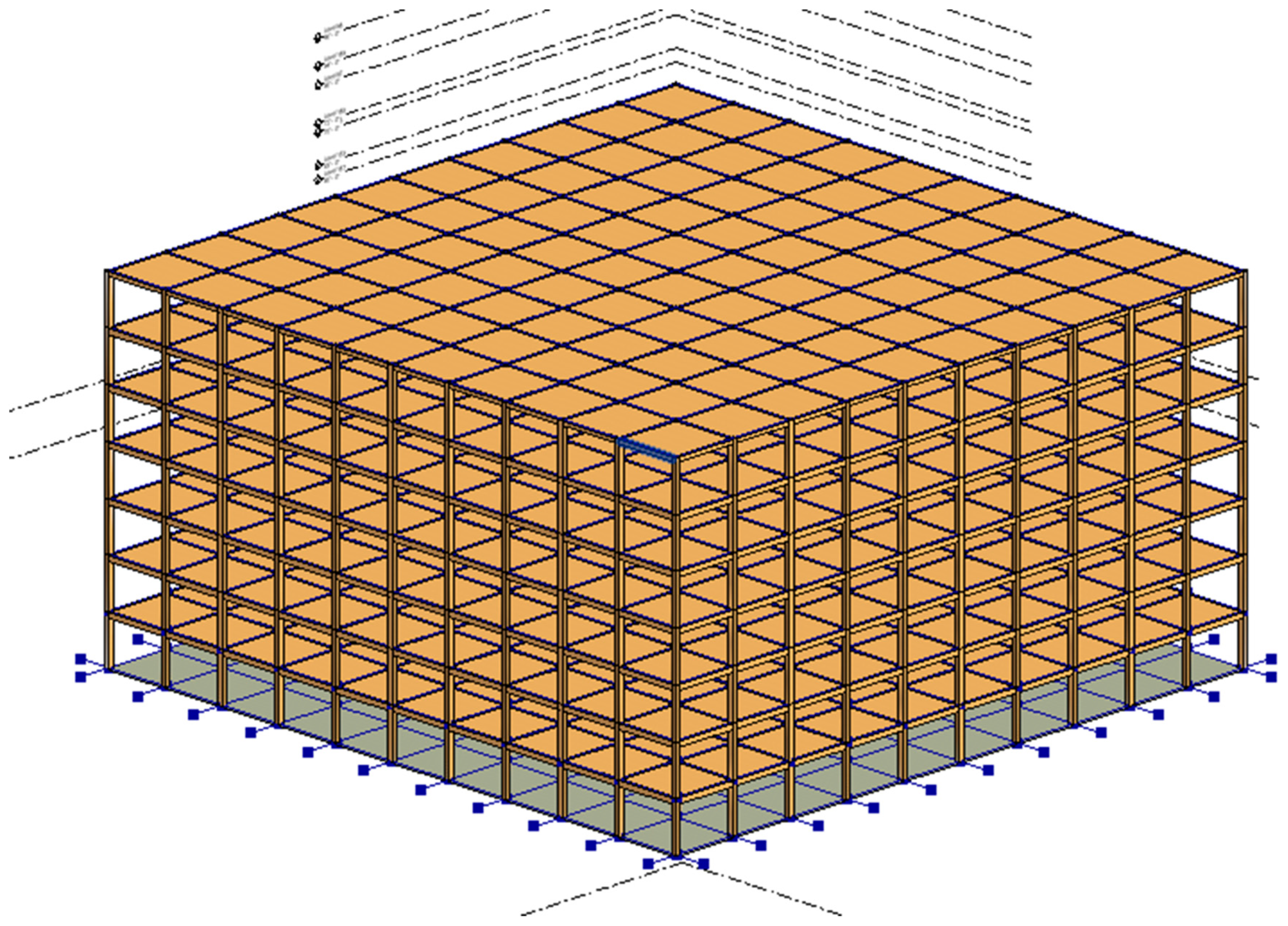
A similar section of code was developed for the floor beams, roof beams, columns, and floor panels. With families created and the code successfully converting its outputs to a data format that Revit can use, the 3D model is generated. Figure 5 is an example of these models. The model will update member sizes after each run of the script.
Figure 5.
Seven-story, ten-bay square, three-dimensional Revit model.
The model always depicts a concrete slab on grade at the lowest level, with the remaining floors shown as the correct CLT thickness. The beams and columns show evident changes when their dimensions change, and by clicking an individual element, the user can see the size of that member. The model is an interactive view of the results of the design.
3.7. Material Takeoff and Carbon Accounting
One of the primary goals of this script was to quickly calculate an estimate of the embodied carbon for a given building layout. An accurate accounting of carbon requires a measure of how much material will be used in the building. For this script, the material take-off calculates the volume of glulam as well as the volume of CLT. The volume of a single column was calculated and then multiplied by the total number of columns. The same was performed for the beams and then added to the column total to receive the total volume of glulam. The volume of CLT was determined by taking the panel thickness times the total square meterage. An environmental product declaration is a document that outlines the environmental impact of a product or material. These documents include information on the global warming potential and a variety of other important environmental factors. Global warming potential (GWP) is a measure of how much carbon dioxide is released per unit volume or weight of material. The script allows the user to input a GWP from an EPD of their choosing. Currently, the script utilizes the EPDs supplied by Nordic on their mass timber products. These EPDs state a 122 kg CO2 e/m2 for CLT and a 100 kg CO2 e/m2 for glulam. With both volumes calculated, it is a simple multiplication to determine the GWP for both materials, which can then be added to obtain the overall embodied carbon for the given model. A common way to display the GWP or embodied carbon intensity of a project is in terms of embodied carbon per square meter of floor. The script returns this value as well as a ratio of volume of mass timber to total square meterage, which is a useful indicator of project feasibility. It should be noted that the APDT does not account for EC from later life-cycle stages such as construction, use/maintenance, and end-of-life.
4. Results, Applications, and Examples
4.1. Script in Dynamo Player
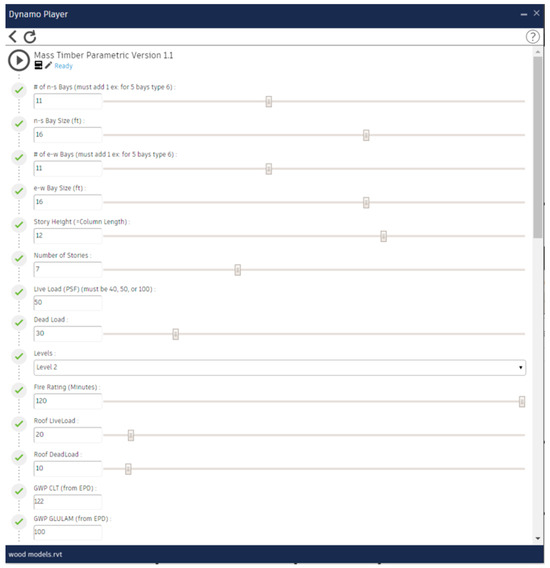
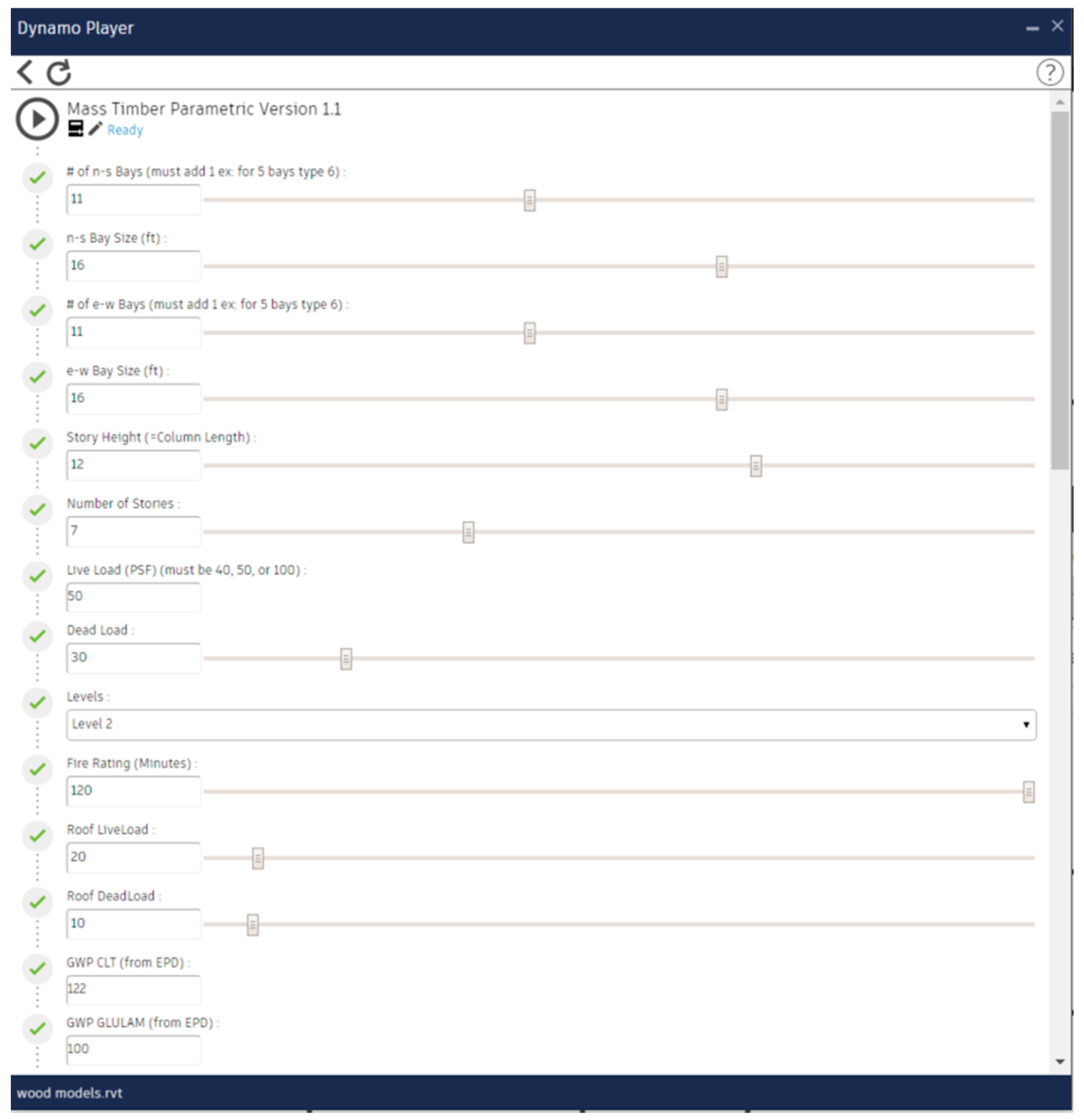
The completed script can be run in any Revit model if the Excel database file is correctly pathed and the beam and column families are imported into the model. For ease of use, the Dynamo file, Excel database, families, and a working Revit model can all be saved in one folder. This creates a system that allows anyone with access to this folder to run the script without the need to re-path the Excel file or load the Revit families. If the Excel file is moved, a new Revit model is created, or the script is being run on a device outside of the ecosystem containing the folder with all the necessary files, it will be necessary to check that these items are imported correctly. Assuming the setup is correct, the script can easily be run using Dynamo Player. Dynamo Player is the interface that Revit uses to run Dynamo Scripts without having to open the script itself. The interface allows the user to adjust the inputs, run the script, and see the results and outputs all in the same place. Figure 6 shows how the script is represented in Dynamo Player.
Figure 6.
Dynamo Player with design input parameters.
Most inputs are programmed as sliders that can be adjusted up or down based on what the user is trying to achieve. The inputs can also simply be edited by typing a number in the respective box. Some of the inputs, such as live load and fire rating, are restricted to a few values. Live load must be either 1.9, 2.4, or 4.8 kN/m2 due to the way the CLT design table was set up. The fire rating is restricted to 30 min intervals up to 2 h, which encapsulates all the typical fire ratings that may be required in mass timber design. The dead load slider has a range of 1–4.5 kN/m2, but is limited to increments of 0.5, once again due to how the CLT design table was set up. The number of stories is not limited in the script, but limits are imposed on the maximum mass timber building height by the international building code and other applicable design codes. Bay size can currently range from 1.8 to 6.7 m, and the maximum story height is 4.5 m. When all the inputs are set, the play button will run the script, which will generate the model and display the other results, like the material take off and embodied carbon values. The results are displayed directly in Dynamo Player, but an Excel spreadsheet was also built that displays the results and outputs in a more organized manner.
4.2. Applications
The goal for this tool is to make it easier to assess the viability of mass timber as a structural system. The tool accomplishes this by presenting preliminary data about the mass timber system almost immediately. The parametric nature of the tool allows for different design ideas to be tested and the member sizes, material quantities, and embodied carbon data to be compared. These features are especially helpful in a scenario where a building is being proposed, and only concrete and steel systems are being considered. Mass timber can quickly be thrown into the conversation using this tool and may show the engineer/architect/owner that mass timber is feasible and comes with the added benefit of being low-carbon. This tool was created for the preliminary and conceptual phases of project design when structural systems are being considered. Once mass timber is deemed feasible, additional detailed design will be required.
4.3. Limitations
It must be noted that the APDT presented calculates cradle-to-gate (A1–A3) embodied carbon using generic manufacturer EPDs and does not include a full life cycle assessment. The script has a few limitations in terms of modeling and design. Calculations are conducted for corner columns, edge columns, and interior columns, but it is not possible to visually model the three different column types, so all columns visually appear as interior columns. Another conservative element of the column design is that all columns are designed and sized for the maximum load on the first floor. This creates columns that are adequately designed on the lower floors but over-designed on the upper floors. It is difficult to account for the differing column loads in the parametric models since the number of floors is always changing. This conservativeness yields a feasible design but involves more material; consequently, the embodied carbon values are conservative. Assuming no special design considerations, this simplification likely leads to a material overestimation of approximately two to five percent for the upper floors in a typical seven-story building.
Another limitation in this script is in the beam layout. The load path consists of a cross-laminated timber (CLT) panel spanning a maximum of 6.7 m, framing into four beams and four columns to create one bay. If spans larger than 6.7 m are desired, infill beams would be required to keep the CLT span at a maximum of 6.7 m. Additionally, the script is based on the 2018 version of the AWC NDS and Nordic Structures [32] tabulated data from 2022. When there are code changes in the future, the script must be updated to reflect these changes. Additionally, this APTD does not consider other building elements (reinforcing steel, HVAC elements, building envelope systems) that could contribute to the EC total.
4.4. Expanded Bays and Warehouse Modeling
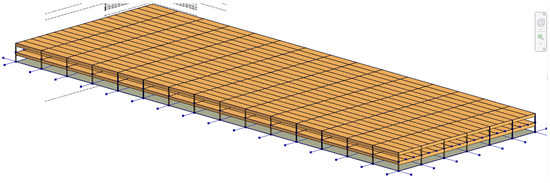
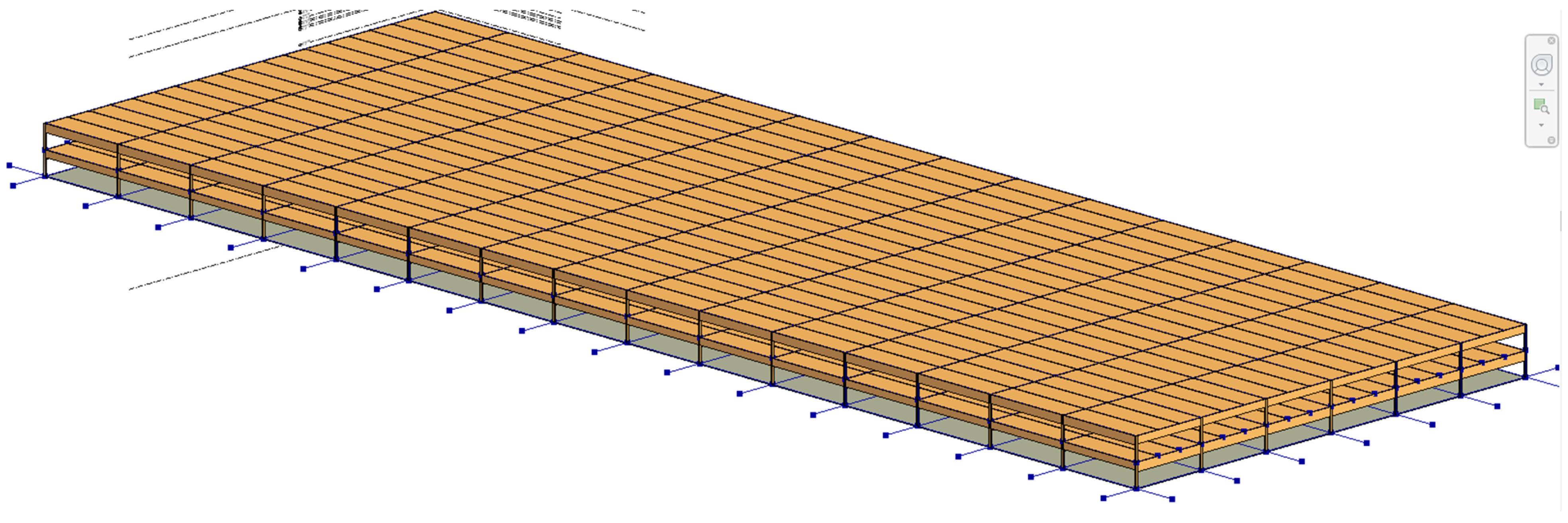
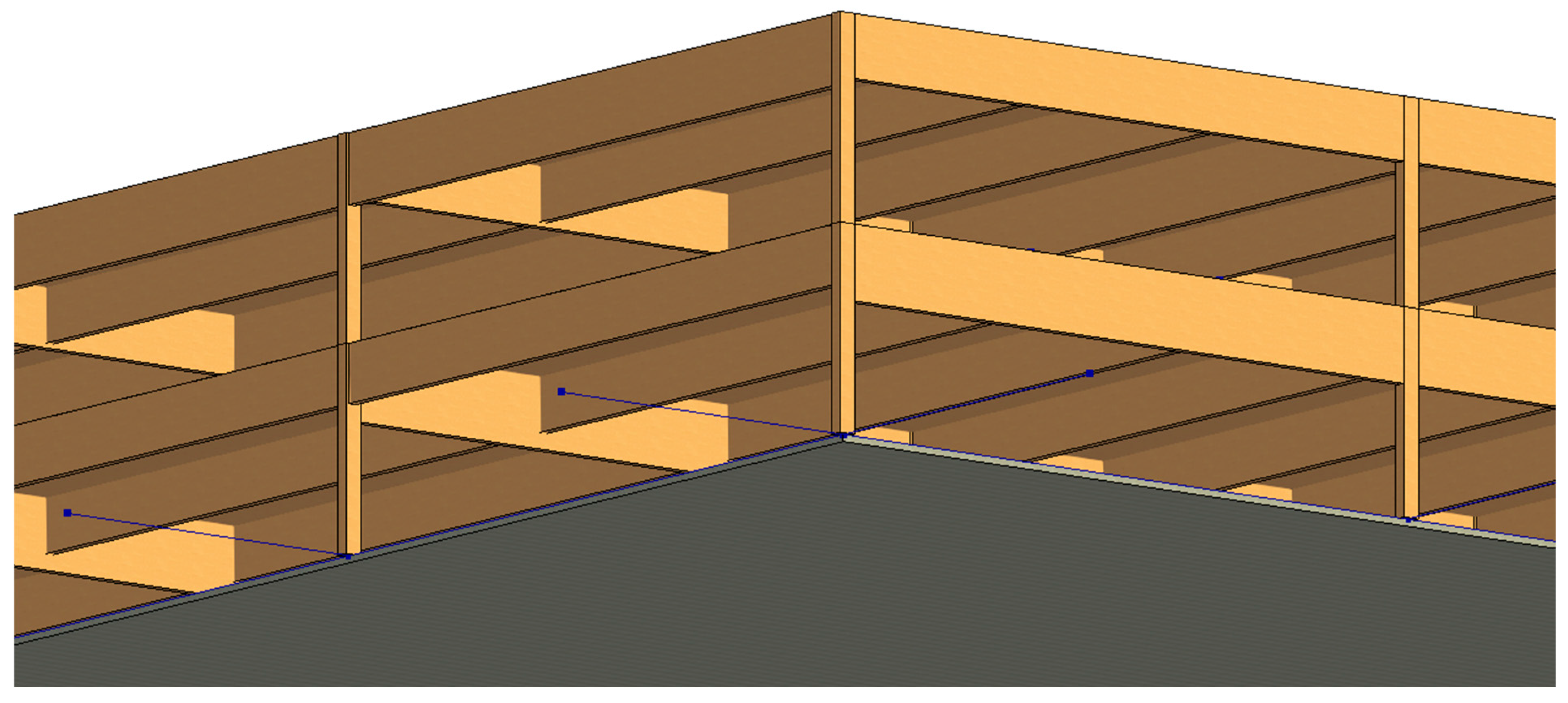
The maximum span of Nordic’s tabulated CLT panels is 6.7 m. The need for additional span arose as the idea of a mass timber warehouse was brought up. The warehouse would ideally have a bay size of around 15 m in both directions. Infill beams were required to limit the span of the CLT panels while allowing for a significantly increased bay size without additional columns. The same grid was used in this version, but additional beam lines were added. Currently, the script can handle up to three infill beams. The number of infill beams selected will be spaced evenly throughout the bay. The infill beams will take the load from the floor panels and transfer it into a long-span girder, which will transfer the load into the columns. The design of these members follows the same process as the original version, with the only difference being the load they are experiencing. The addition of infill beams and the ability to use up to three allows for a much wider range of building sizes and layouts. Using two or three infill beams can create a warehouse-type model with bay sizes over 18 m in either direction. Using one infill can allow for expanding the bay sizes from 6.7 m up to nine meters, which works well for an office or mixed-use building. Limiting the span of the CLT can also reduce the CLT thickness. The longer spans often require seven or sometimes nine ply CLT. This additional thickness increases the volume of mass timber/total square footage ratio. Limiting the span to approximately five meters keeps the CLT at three or five plies, with shorter spans or lower loads, which keeps the volume of mass timber down. Figure 7 depicts a model using two infill beams per bay for bays that span 15 m in the east-west direction (girder span) and 17 m in the north–south direction (infill span). The use of infill beams limits the one-way span of the panels to five meters, which allows them to remain five ply. The infill beams are evident in the view from below, shown in Figure 8. This expanded bay version greatly improves the range of functionality of the script. Both versions are available for use, and options exist to model many more building arrangements.
Figure 7.
Mass timber model of a 225 m (15 bay) × 102 m (6 bay) warehouse.
Figure 8.
Layout of infill beams spanning 15 m, viewed from below.
5. Conclusions and Future Work
This research presents a methodology for creating an APDT using commercially available software, elemental programming, Excel, and existing databases, that allows engineers to evaluate and optimize material selection in building design. The tool provides estimates of material quantities and EC values, thereby making it easier for engineers and owners to consider mass timber when determining the structural system at the infancy stage of the project. The methodology presented can be used to create customized APDTs to support design priorities other than EC. This APDT reduces time and resource barriers to preliminary mass timber analysis, thereby placing material selection at the forefront of the design process and potentially influencing selections toward lower-carbon and sustainable mass timber options.
The methodology presented was used to produce two fully functional parametric mass timber designers. The residential version uses a load path without infill beams and is ideal for modeling residential and smaller office-type layouts. The warehouse and expanded bays version makes use of up to three infill beams. The introduction of infill beams allows for expanded bay sizes up to 18 m. The expanded models are ideal for larger offices and mixed-use buildings up to large warehouses. The tools were built using Autodesk’s Revit and Dynamo, along with Python code. The completed designers take the parametric building characteristics along with the required load and return designed beams, columns, and floor panels that meet both strength and fire rating requirements. The calculations were verified with an example performed by hand and prove that the designer is accurate and follows NDS requirements for mass timber design. The goal of these tools is to provide the information needed to optimize material selection based on embodied carbon. Providing an optimized design to the engineer can demonstrate mass timber’s feasibility for a given project layout, which will be helpful when discussing possible material systems. These optimized designs should encourage the selection of mass timber for structural systems.
The use of additional wood product manufacturer databases may provide the designer with more options. A significant upgrade that can be made to these scripts is the addition of mass timber cost data from manufacturers. Relevant local cost data was not yet available, but the script does a material take-off to calculate the embodied carbon values, so cost data can easily be implemented once available. Knowing the amount of material and its associated cost can quickly provide an estimate of the total cost of the project. This will only enhance the usefulness of this tool because it can demonstrate mass timber’s overall feasibility, calculate embodied carbon levels, and provide a rough cost estimate. Adding a script that allows designers to conduct side-by-side comparisons of total EC and EC per m2 for multiple designs would be of significant value.
Author Contributions
Conceptualization, S.M.A.; Methodology, E.A.B., D.W.D. and S.M.A.; Software, E.A.B.; Validation, E.A.B. and S.M.A.; Formal analysis, E.A.B.; Investigation, E.A.B. and D.W.D.; Resources, S.M.A.; Data curation, E.A.B.; Writing—original draft, E.A.B. and D.W.D.; Writing—review & editing, S.M.A.; Visualization, E.A.B.; Supervision, D.W.D. and S.M.A.; Project administration, D.W.D.; Funding acquisition, D.W.D. and S.M.A. All authors have read and agreed to the published version of the manuscript.
Funding
This research was funded by Bala Consulting Engineers, Inc., VU index 529972-202. Tuition funding was provided by Villanova University.
Data Availability Statement
The original contributions presented in this study are included in the article. Further inquiries can be directed to the author S.M.A.
Acknowledgments
The authors are grateful for the participation and financial support of Bala Consulting Engineers, Inc. During this study, the authors used Autodesk’s Revit: Dynamo, 2022, for the purposes described. The authors have reviewed and edited the output and take responsibility for the content of this publication.
Conflicts of Interest
Author Edward A. Barnett is currently employed at Worley Ltd. Author Edward A. Barnett was a graduate student intern and author Steven M. Anastasio is employed at Bala Consulting Engineers, Inc. The remaining author declares that the research was conducted in the absence of any commercial or financial relationships that could be construed as a potential conflict of interest. The authors declare that this study received funding from Bala Consulting Engineers, Inc. The funder was not involved in the study design, collection, analysis, interpretation of data, the writing of this article or the decision to submit it for publication.
Abbreviations
The following abbreviations are used in this manuscript:
| AISC | American Institute of Steel Construction |
| AS | Allowable Stress Design |
| APDT | Automated Parametric Design Tool |
| BIM | Building Information Modeling |
| CLT | Cross Laminated Timber |
| CV | Volume Factor for Glulam Beams |
| DSE | Design Space Exploration |
| EC | Embodied Carbon |
| EPD | Environmental Product Declaration |
| LCA | Life Cycle Assessment |
| MEP | Mechanical, Electrical, and Plumbing |
| NDS | National Design Specification |
References
- U.N. Environment Programme. Global Status Report for Buildings and Construction; U.N. Environment Programme: Nairobi, Kenya, 2024; Available online: http://www.unep.org/resources/report/global-status-report-buildings-and-construction (accessed on 17 December 2025).
- Monteiro, P.J.M.; Miller, S.A.; Horvath, A. Towards sustainable concrete. Nat. Mater. 2017, 16, 698–699. [Google Scholar] [CrossRef] [Scilit]
- Carbon Leadership Forum. 2025. Available online: https://carbonleadershipforum.org/ (accessed on 17 December 2025).
- Hu, M. Strategies and Techniques of Life Cycle–Embodied Carbon Reduction from the Building and Construction Sector: A Review. J. Archit. Eng. 2023, 29, 04023017. [Google Scholar] [CrossRef] [Scilit]
- Pomponi, F.; Moncaster, A. Embodied carbon mitigation and reduction in the built environment—What does the evidence say? J. Environ. Manag. 2016, 181, 687–700. [Google Scholar] [CrossRef] [Scilit]
- Newmarch, E.; Donn, M.; Twose, S.; Dowdell, D.; Short, F. An Urban Feasibility Study into Balancing Upfront Embodied Carbon Emissions Through Integrated Green Areas as Carbon Offsets. In Proceedings of the 2022 Annual Modeling and Simulation Conference (ANNSIM), San Diego, CA, USA, 18–20 July 2022; pp. 631–643. [Google Scholar]
- Eleftheriadis, S.; Duffour, P.; Mumovic, D. BIM-embedded life cycle carbon assessment of RC buildings using optimised structural design alternatives. Energy Build. 2018, 173, 587–600. [Google Scholar] [CrossRef] [Scilit]
- Morris, F.; Allen, S.; Hawkins, W. On the embodied carbon of structural timber versus steel, and the influence of LCA methodology. Build. Environ. 2021, 206, 108285. [Google Scholar] [CrossRef] [Scilit]
- Al-Obaidy, M.; Courard, L.; Attia, S. A Parametric Approach to Optimizing Building Construction Systems and Carbon Footprint: A Case Study Inspired by Circularity Principles. Sustainability 2022, 14, 3370. [Google Scholar] [CrossRef] [Scilit]
- Mohamed, R.A.; Alwan, Z.; Salem, M.; McIntyre, L. Automation of embodied carbon calculation in digital built environment- tool utilizing UK LCI database. Energy Build. 2023, 29, 113528. [Google Scholar] [CrossRef] [Scilit]
- Ma, L.; Azari, R.; Elnimeiri, M. A Building Information Modeling-Based Life Cycle Assessment of the Embodied Carbon and Environmental Impacts of High-Rise Building Structures: A Case Study. Sustainability 2024, 16, 569. [Google Scholar] [CrossRef] [Scilit]
- Parece, S.; Resende, R.; Rato, V. A BIM-based tool for embodied carbon assessment using a Construction Classification System. Dev. Built Environ. 2024, 19, 100467. [Google Scholar] [CrossRef] [Scilit]
- Parece, S.; Resende, R.; Rato, V. BIM-based life cycle assessment: A systematic review on automation and decision-making during design. Build. Environ. 2025, 282, 113248. [Google Scholar] [CrossRef] [Scilit]
- Szalay, Z. A parametric approach for developing embodied environmental benchmark values for buildings. Int. J. Life Cycle Assess. 2024, 29, 1563–1581. [Google Scholar] [CrossRef] [Scilit]
- Huang, B.; Zhang, H.; Yang, W.; Ye, H.; Jiang, B. Mechanical carbon emission assessment during prefabricated building deconstruction based on BIM and multi-objective optimization. Sci. Rep. 2024, 14, 27103. [Google Scholar] [CrossRef] [Scilit]
- Keyhani, M.; Bahadori-Jahromi, A.; Godfrey, P.B. A Comparative Study of Traditional vs. Automated BIM-LCA Methods for Embodied Carbon Assessment. Eng. Future Sustain. 2024, 1. [Google Scholar] [CrossRef] [Scilit]
- Bacheva, T.S.; Grau, J.F.R. Embodied Impacts in Buildings: A Systematic Review of Life Cycle Gaps and Sectoral Integration Strategies. Buildings 2025, 15, 1661. [Google Scholar] [CrossRef] [Scilit]
- Ferreira, M.T.H.A.; Costa, A.A.; Silvestre, J.D. Environmental optimization and benchmarking of walls through a BIM plugin. Archit. Eng. Des. Manag. 2025, 1–30. [Google Scholar] [CrossRef] [Scilit]
- Huang, B.; Zhang, H.; Ullah, H.; Lv, Y. BIM-based embodied carbon evaluation during building early-design stage: A systematic literature review. Environ. Impact Assess. Rev. 2025, 112, 107768. [Google Scholar] [CrossRef] [Scilit]
- Zhang, Y.; Sattar, S.; Cook, D.T.; Johnson, K.J.; Fung, J.F. Systematic Review of Embodied Carbon Assessment and Reduction in Building Life Cycles: An Integrated Approach to Resilience and Sustainability. NIST Special Publication 1324. 2024. Available online: https://nvlpubs.nist.gov/nistpubs/SpecialPublications/NIST.SP.1324.pdf (accessed on 14 December 2025).
- Helal, J.; Stephan, A.; Crawford, R.H. Integrating embodied greenhouse gas emissions assessment into the structural design of tall buildings: A framework and software tool for design decision-making. Energy Build. 2023, 297, 113462. [Google Scholar] [CrossRef] [Scilit]
- Dicko, A.H.; Roux, C.; Peuportier, B. Achieving Net Zero Carbon Performance in a French Apartment Building? Energies 2023, 16, 7608. [Google Scholar] [CrossRef] [Scilit]
- Morales-Beltran, M.; Engür, P.; Şişman, Ö.A.; Aykar, G.N. Redesigning for Disassembly and Carbon Footprint Reduction: Shifting from Reinforced Concrete to Hybrid Timber–Steel Multi-Story Building. Sustainability 2023, 15, 7273. [Google Scholar] [CrossRef] [Scilit]
- Zhang, X.; Huang, W.; Khajehpour, M.; Asgari, M.; Tannert, T. Seismic Performance and LCA Comparison between Concrete and Timber–Concrete Hybrid Buildings. Buildings 2023, 13, 1714. [Google Scholar] [CrossRef] [Scilit]
- Huang, B.; Xing, K.; Rameezdeen, R. Exploring Embodied Carbon Comparison in Lightweight Building Structure Frames: A Case Study. Sustainability 2023, 15, 15167. [Google Scholar] [CrossRef] [Scilit]
- Greene, J.M.; Hosanna, H.R.; Willson, B.; Quinn, J.C. Whole life embodied emissions and net-zero emissions potential for a mid-rise office building constructed with mass timber. Sustain. Mater. Technol. 2023, 35, e00528. [Google Scholar] [CrossRef] [Scilit]
- Almulhim, M.S.M.; Taher, R. Environmental impact assessment of residential building structural systems: A case study in Saudi Arabia. J. Build. Eng. 2023, 72, 106644. [Google Scholar] [CrossRef] [Scilit]
- Leonard, S.J.; Solnosky, R. Guiding Mass Timber Design and Research: A Parametric Modeling Approach to Understanding Impacts. In Proceedings of the Structures Congress 2023, New Orleans, LA, USA, 3–6 May 2023. [Google Scholar]
- Autodesk. Autodesk Revit 2022; Autodesk, Inc.: San Francisco, CA, USA, 2022. [Google Scholar]
- Autodesk. Autodesk Dynamo 2022; Autodesk, Inc.: San Francisco, CA, USA, 2022. [Google Scholar]
- Microsoft Corporation. Microsoft® Excel® for Microsoft 365 MSO; Version 2403 Build 16.0.17425.20124; Microsoft Corporation: Redmond, WA, USA, 2024. [Google Scholar]
- Nordic Structures|Nordic.ca|Engineered Wood|Products|Nordic X-Lam Cross-Laminated Timber (CLT). Available online: https://www.nordic.ca/en/products/nordic-x-lam-cross-laminated-timber-clt (accessed on 1 February 2022).
- Nordic Structures|Nordic. Ca|Engineered Wood|Products|Nordic Lam+ Glued-Laminated Timber (Glulam). Available online: https://www.nordic.ca/en/products/nordic-lam-plus-glued-laminated-timber-glulam (accessed on 21 April 2022).
- AISC. Steel Construction Manual, 15th ed.; AISC: Chicago, IL, USA, 2017. [Google Scholar]


Disclaimer/Publisher’s Note: The statements, opinions and data contained in all publications are solely those of the individual author(s) and contributor(s) and not of MDPI and/or the editor(s). MDPI and/or the editor(s) disclaim responsibility for any injury to people or property resulting from any ideas, methods, instructions or products referred to in the content. |
© 2026 by the authors. Licensee MDPI, Basel, Switzerland. This article is an open access article distributed under the terms and conditions of the Creative Commons Attribution (CC BY) license.