


Abstract
This study investigates the dynamic efficacy of Fluid Viscous Dampers (FVDs) in mitigating lateral story drift and attenuating seismic base shear forces in multi-story steel moment-resisting frames (MRFs) subjected to contrasting geotechnical site conditions. Archetype steel structures with 5, 10, and 15 stories were designed in full compliance with the Turkish Building Earthquake Code (TBDY-2018) and AISC 360-16 specifications, considering hard rock (ZA) and soft, deep sedimentary soil deposits (ZE) for high-seismicity coordinates along the East Anatolian Fault zone (Pazarcık, Kahramanmaraş). A suite of 11 real earthquake acceleration pairs (22 horizontal components) compiled from the AFAD TADAS database was spectrally matched to code-compliant target elastic response spectra using continuous wavelet transforms. Direct integration nonlinear time-history analyses (NL-THA) were executed using the Newmark average acceleration method. Modal eigenvalue analyses confirm that supplemental diagonal FVDs preserve the fundamental natural vibration periods of the frames (T1 = 0.70 s, 1.53 s, and 1.53 s for the 5-, 10-, and 15-story archetypes, respectively) without imposing secondary elastic stiffness penalties. The nonlinear dynamic findings demonstrate that FVD integration reduces peak lateral floor displacements by 54.59% to 88.05% and suppresses maximum base shear demands by 69.10% to 85.29% across all heights and shaking directions. Notably, under soft soil (ZE) excitations where unprotected bare frames develop severe interstory drift concentrations (up to 3.18%), the FVD systems consistently restrict maximum interstory drift ratios (IDRs) below the 0.80% damage-control limit, keeping peak drift demands within the threshold conventionally associated with elastic or near-elastic frame response, thereby indicating a low likelihood of plastic hinge formation and precluding second-order P − Δ collapse mechanisms.
1. Introduction
Severe seismic events recorded over the past three decades—notably the 1994 Northridge (Mw 6.7), 1995 Hyogo-ken Nanbu (Mw 6.9), 1999 Kocaeli (Mw 7.4), and the destructive February 6, 2023 Kahramanmaraş earthquake sequence (Mw 7.7 and Mw 7.6)—have exposed the socioeconomic and structural limitations of conventional ductility-based design philosophies [1,2,3]. Standard building specifications, such as the Turkish Building Earthquake Code (TBDY-2018) and ASCE 7-22, permit primary structural members to undergo substantial inelastic hysteretic deformation during design-basis and maximum considered earthquakes [2,4]. In classical steel moment-resisting frames (MRFs), seismic input energy is dissipated predominantly through flexural plastic hinging at beam ends and severe shear yielding within beam-to-column panel zones [1,5]. While this sacrificial mechanism is theoretically calibrated to prevent catastrophic collapse and satisfy immediate life-safety thresholds, it inherently results in severe structural stiffness degradation, extensive interstory drift concentrations, and unrecoverable residual drift offsets [5,6]. Following severe earthquakes, the financial expenditure required to inspect, realign, or replace damaged structural members frequently reaches or exceeds the initial replacement value of the facility [6,7]. Consequently, contemporary earthquake engineering has pivoted decisively from simple collapse prevention toward resilient, low-damage design strategies capable of ensuring rapid post-earthquake functionality [2,7].
To shield the primary load-bearing skeleton from irreversible plastic deformations, structural control systems utilizing supplemental passive damping mechanisms have emerged as an effective alternative [1,8,9]. Early engineering adaptations concentrated on displacement-dependent hysteretic devices, most notably metallic yielding dampers, such as Added Damping and Stiffness (ADAS) and Triangular ADAS (TADAS) devices [10,11], as well as dry-friction dampers utilizing Slotted Bolted Connections (SBC) [12,13]. Although metallic dampers dissipate energy through stable plastic shear or flexural yielding of ductile plates [10] and friction dampers dissipate energy via Coulomb sliding friction [12], both typologies impose significant structural tradeoffs [1]. Primarily, because their activation relies on lateral displacement, they inherently introduce substantial secondary elastic stiffness into the framing [1,11]. This stiffness injection abruptly shortens the fundamental natural vibration periods of the structure, drawing higher pseudo-spectral acceleration demands from the earthquake spectrum and subsequently transmitting heightened base shear and axial shock loads to the foundation [1,13]. Furthermore, metallic units necessitate complete physical replacement following a major event, while friction dampers remain susceptible to stick-slip locking and permanent post-shaking drift offsets [1,12].
In sharp contrast to displacement-activated devices, Fluid Viscous Dampers (FVDs)—adapted from high-precision aerospace and defense shock-mitigation technologies—operate as pure velocity-dependent passive control mechanisms [7,8]. Seminal experimental and analytical investigations by Constantinou and Symans [7,14] formulated the dynamic constitutive modeling of FVDs, establishing that forcing specially compounded, compressible silicone fluid through micron-scale orifice channels within a stainless-steel cylinder generates substantial hydraulic head losses and internal viscous shear [7,15]. Importantly, rigorous analytical derivations and frequency-sweep experiments by Makris et al. [16,17] proved that across the low structural frequency band typical of civil engineering structures (f ≤ 4.0 Hz), properly engineered through-rod FVDs act as pure dashpots, introducing virtually zero parasitic storage stiffness [16,17]. From a structural dynamics standpoint, because the generated damping force is an explicit function of relative piston velocity rather than interstory displacement, the peak damping resistance occurs at the zero-displacement crossing where the structural velocity is maximal, establishing a 90-degree phase lead over displacement [1,14]. Conversely, at maximum lateral story excursion where column bending moments and chord rotations reach their maximum, the relative velocity drops to zero, causing the instantaneous damper force to vanish [1,7]. This mechanical orthogonality ensures that supplemental damping forces do not superimpose directly onto peak structural internal forces, avoiding the need to upsize adjacent beams, columns, and foundations [7,15].
Expanding upon this mechanical premise, subsequent research has demonstrated the versatility of viscous dampers across varied structural configurations. Constantinou et al. [18] introduced toggle-brace magnification mechanisms to amplify relative velocities across dampers in stiff, low-drift structural frames [18]. For irregular configurations, Goel [19] as well as Lin and Chopra [20] proved that strategically positioned FVDs suppress coupled lateral-torsional vibrations without requiring costly modifications to structural centers of mass or stiffness [19,20]. To optimize installation efficiency, Lopez Garcia and Soong [21,22] established simplified sequential search algorithms (SSSA), demonstrating that non-uniform damper layouts reduce interstory drift demands with fewer physical devices [21,22]. In tall structures, McNamara and Taylor [23] highlighted the multi-hazard efficiency of FVDs in suppressing high-frequency vortex shedding and wind-induced accelerations [23]. Furthermore, Lin and Chopra [24] demonstrated that nonlinear fluid viscous dampers characterized by velocity exponents α < 1.0 dissipate significantly greater hysteretic energy per cycle by forming near-rectangular hysteresis loops while imposing a strict physical ceiling on peak damper forces transferred to connection gusset plates during sudden velocity pulses [24]. More recently, Chalarca et al. [25] quantified the influence of fluid viscous damper stiffness on floor acceleration demands in steel moment-resisting frames, confirming the sensitivity of nonstructural response to damper assembly properties [25].
Despite the extensive body of literature validating FVD mechanics, a major unresolved research challenge lies in the complex interplay between structural aspect ratio (building height) and geotechnical soil amplification effects under severe ground motions [26,27,28]. Local soil strata act as physical filters that fundamentally alter the frequency content, amplitude, and strong-motion duration of seismic waves propagating from bedrock to the ground surface [2,29]. When deep, soft clay or loose sand deposits (categorized as Soil Class ZE in TBDY-2018 or Site Class E in ASCE 7-22) overlie bedrock, low-frequency seismic waves undergo severe site amplification, substantially elevating spectral accelerations in the medium-to-long period range (T > 1.0 s) [2,26]. Mid-rise and high-rise steel moment frames inherently possess elongated fundamental periods that fall squarely within this amplified long-period spectral plateau [2,27]. Under such conditions, unprotected flexible frames are subjected to severe resonance-like amplification, triggering localized interstory drift ratio (IDR) spikes and accentuating destabilizing second-order geometric (P − Δ) moments that can lead to dynamic instability and incremental collapse [26].
Recent investigations have begun addressing these geotechnical complexities. Yang et al. [26] conducted large-scale shaking table tests on tall frame structures equipped with viscous dampers and supported by pile foundations in soft soil, observing that pile–soil–structure interaction significantly alters damper efficiency and modifies global seismic demands [26]. Similarly, Hatipoğlu and Düzgün [27] investigated FVD-equipped adjacent structures under soil-structure interaction (SSI) with varying soil profiles using finite element formulations, concluding that structural responses are highly sensitive to the interaction between site stiffness and damper damping coefficients [27]. Complementarily, Yang et al. [30] demonstrated that near-fault ground motions combined with soil–structure interaction substantially modify the effectiveness of viscous dampers on soft sites [30]. In the context of building rehabilitation, Öztürk [31] verified that supplemental FVDs substantially mitigate drift concentrations in existing school structures [31]. However, existing seismic codes (such as TBDY-2018 Chapter 12 and ASCE 7-22 Chapter 18) predominantly formulate supplemental damping provisions based either on idealized rigid rock assumptions or for isolated single-building scenarios [2,4]. A systematic, multi-record nonlinear assessment investigating the progressive influence of building height (5-, 10-, and 15-story archetypes) coupled with extreme geotechnical amplification contrasts (hard rock ZA vs. highly soft soil ZE) under identical bidirectional real near-fault earthquakes remains unaddressed in the literature [2,26,27].
To bridge this critical knowledge gap, this paper presents a comprehensive comparative investigation into the nonlinear dynamic performance of 5-, 10-, and 15-story benchmark steel moment-resisting frames equipped with diagonally configured fluid viscous dampers. Designed in full accordance with TBDY-2018 under high-seismicity coordinates on the East Anatolian Fault (Pazarcık, Kahramanmaraş), the archetypes are subjected to 11 pairs of spectrally matched real acceleration records, including near-fault ruptures from the 2023 Pazarcık and Elbistan events. Through direct integration nonlinear time-history analyses (NL-THA), this study comprehensively examines: the modal invariance and zero-stiffness preservation of structural natural vibration periods (T1,T2); the attenuation of peak seismic base shear forces (Vb) across contrasting soil classes (ZA vs. ZE); and the height-wise mitigation of lateral floor displacement envelopes and interstory drift ratios (IDRs) against performance-based collapse prevention criteria (≤0.80%). The principal novelty of this work lies in the systematic quantification of the coupled height–site-class interaction for FVD-equipped steel frames under an identical suite of spectrally matched real bidirectional records—including 2023 Kahramanmaraş mainshock stations—thereby providing code-relevant benchmark data absent from current supplemental damping provisions.
2. Theoretical Formulation and Maxwell Viscoelastic Damper Modeling
The mechanical behavior of Fluid Viscous Dampers (FVDs) under transient seismic excitations is governed by the macroscopic pressure differential developed across the internal piston head as silicone fluid is forced through micron-scale orifice passages [7,15]. Over the operating frequency bandwidth of typical civil structures (f ≤ 4.0 Hz), through-rod fluid viscous dampers behave as purely velocity-dependent mechanisms [16]. The generalized nonlinear constitutive relationship relating the generated damping force Fd(t) to the relative piston velocity is mathematically expressed as by Equation (1):
where Fd(t) denotes the instantaneous axial damping force, Cd represents the damping coefficient, is the relative velocity vector across the damper connection pins, α is the dimensionless velocity exponent (0.3 ≤ α ≤ 1.0), and sgn(⋅) is the signum function dictating directional polarity.
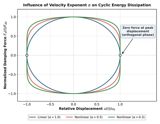
The velocity exponent α in Equation (1) controls the geometric curvature of the force–velocity relationship and governs the cyclic energy dissipation capacity of the device. Under steady-state harmonic excitation u(t) = u0sin(ωt) with circular frequency ω, the relative velocity vector leads displacement by a 90-degree phase angle (). For a linear viscous damper where α = 1.0, Equation (1) reduces to , producing the pure elliptical hysteresis trajectory illustrated in Figure 1. Integrating the force over a complete displacement cycle yields the cyclic hysteretic energy dissipated per cycle (ED), expressed in Equation (2):
Figure 1.
Normalized cyclic force–displacement hysteresis loops of fluid viscous dampers under harmonic loading: influence of velocity exponent (α) in Equation (1) on cyclic energy dissipation capacity and illustration of the 90-degree phase orthogonality at peak lateral displacement (Fd = 0 at u = ±u0).
When nonlinear fluid viscous dampers with fractional exponents (α < 1.0) are specified, Equation (1) alters the force–displacement hysteresis loop toward a near-rectangular geometry (Figure 1). As shown in Figure 1, reducing α from 1.0 to 0.3 significantly expands the enclosed loop area, driving cyclic energy dissipation toward the theoretical upper bound ED ≈ 4Fd0u0. Simultaneously, the fractional exponent in Equation (1) limits the peak axial force Fd0 generated during sudden seismic velocity pulses, mitigating local stress concentrations across adjacent framing joints. Furthermore, as demonstrated by the zero-force crossing in Figure 1, when lateral story displacement reaches its peak amplitude (u = ±u0), the relative velocity drops to zero (), causing the instantaneous damping force from Equation (1) to vanish (Fd = 0). This mechanical phase quadrature prevents peak damping forces from coinciding with peak column bending moments.
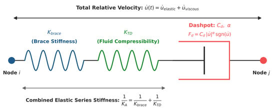
In physical structural installations, an FVD is mounted in series with structural driver braces and gusset connection plates rather than acting as an isolated dashpot. To capture this combined viscoelastic flexibility, the assembly is characterized via the classical Maxwell model depicted in Figure 2. The Maxwell model accounts for the axial elastic stiffness of the driver extension brace (Kbrace) and the internal fluid compressibility stiffness of the damper cylinder body (KTD) acting in series with the viscous dashpot. The combined effective series stiffness (KA) of the assembly is formulated in Equation (3):
Figure 2.
Schematic configuration of the lumped Maxwell viscoelastic mechanical model governed by Equations (3)–(5), depicting the series coupling of driver extension brace stiffness (Kbrace), internal cylinder fluid compressibility (KTD), and the nonlinear viscous dashpot element (Cd,α).
Because all elements in Figure 2 are coupled in series, the total axial force Fd(t) developed across the system remains uniform. The total relative velocity across the attachment nodes () represents the summation of the elastic deformation rate () derived from Equation (3) and the nonlinear dashpot velocity formulated from Equation (1). This interaction is governed by the differential constitutive equation in Equation (4):
For the linear damper case (α = 1.0) investigated in this paper, Equation (4) simplifies to Equation (5):
In the numerical modeling of the 5-, 10-, and 15-story archetypes in SAP2000 (SAP2000 v27, Computers and Structures, Inc., Walnut Creek, CA, USA), diagonal FVD braces along the central bays were defined using nonlinear 2-joint Damper Link elements operating exclusively along their local longitudinal axis (U1). The mechanical properties in Equations (3) and (5) were calibrated according to manufacturer empirical test data for Taylor Devices Model 17120-X (Taylor Devices Inc., North Tonawanda, NY, USA): effective assembly stiffness KA = 164,617.96 kN/m, damping coefficient Cd = 29,682.97 kN ⋅ s/m, and linear velocity exponent α = 1.0.
3. Structural Modeling and Ground Motion Characterization
3.1. Benchmark Structural Archetypes and Cross-Sectional Detailing
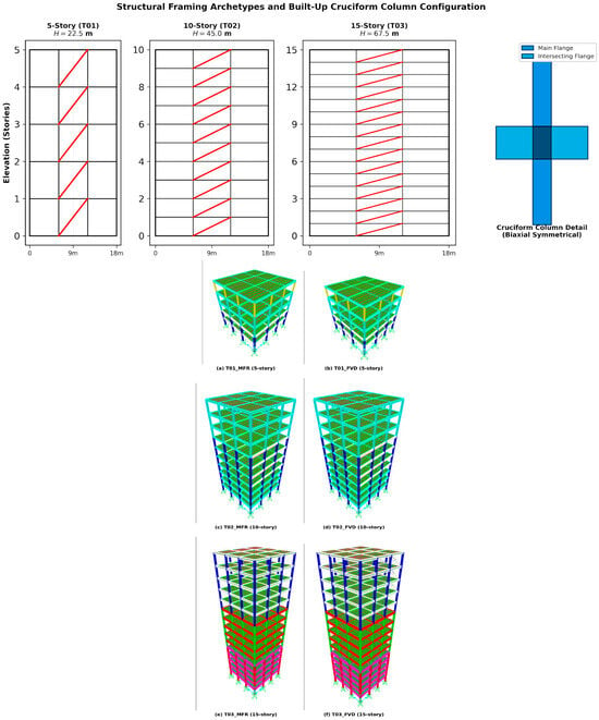
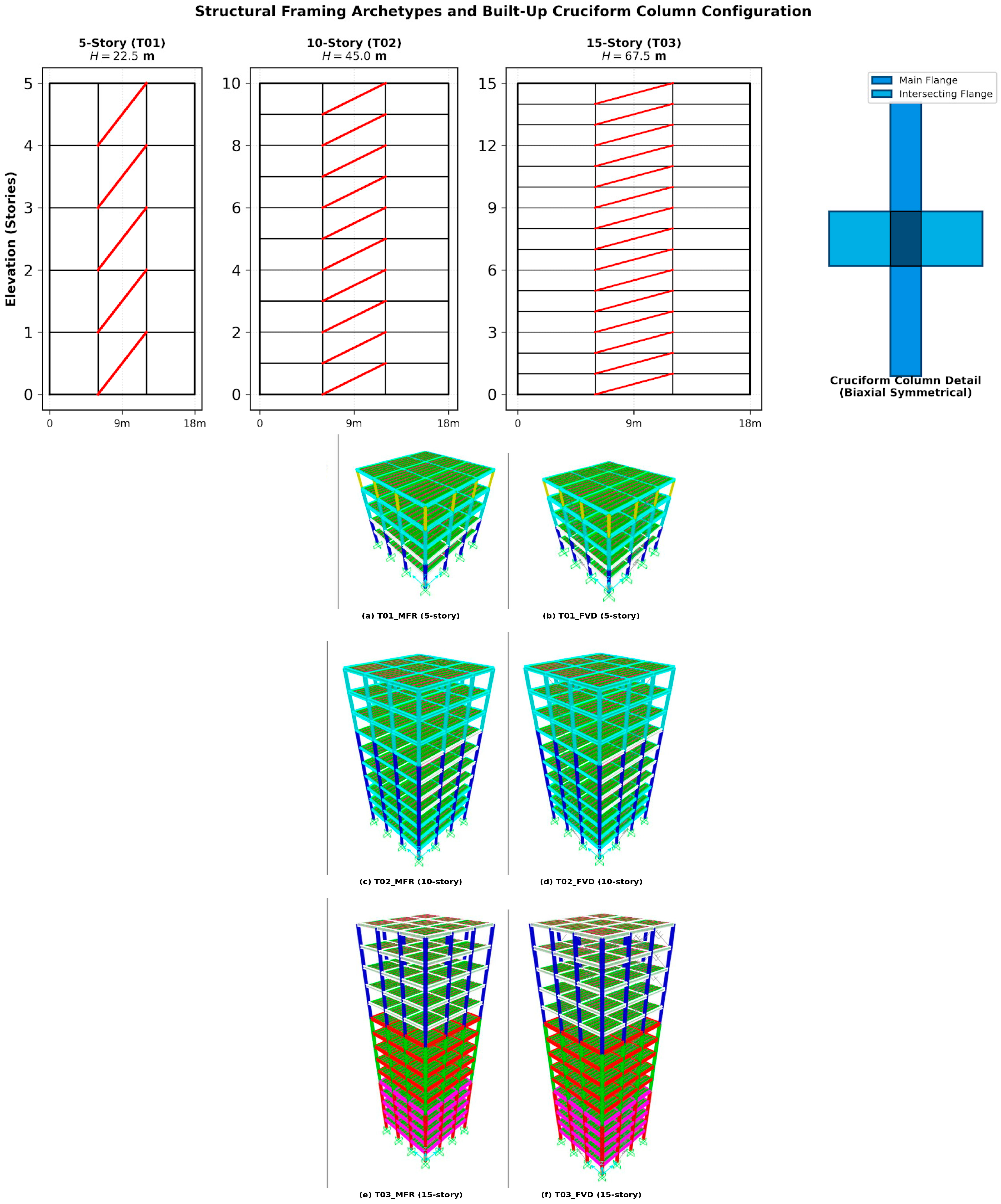
To investigate the coupled influence of structural aspect ratio and supplemental damping across contrasting dynamic vibration regimes, three symmetric three-dimensional steel moment-resisting frames (MRFs) representing low-rise (5-story/22.5 m), mid-rise (10-story/45.0 m), and high-rise (15-story/67.5 m) typologies were designed in strict compliance with the Turkish Building Earthquake Code (TBDY-2018) and AISC 360-16 specifications. As illustrated in Figure 3, each structural archetype possesses an identical square footprint of 18.0 m × 18.0 m (324 m2 floor diaphragm area) configured with three equal bays of 6.0 m in both orthogonal horizontal axes (X and Y directions). The typical story height is kept constant at 4.5 m from the base elevation to the roof level across all structural elevations. The plan symmetry in both orthogonal directions eliminates accidental torsional eccentricity and rules out planar irregular torsion modes (A1 type irregularity in TBDY-2018), isolating pure translational and interstory drift responses under multi-directional shaking.
Figure 3.
Three-dimensional SAP2000 views of the bare (MFR) and FVD-equipped benchmark steel moment-resisting frames: (a,b) 5-story T01; (c,d) 10-story T02; (e,f) 15-story T03, together with the structural elevation schemes and cross-sectional geometry of the biaxially symmetrical built-up cruciform columns.
To accommodate high axial gravity forces and severe bidirectional overturning moments without favoring a single bending axis, built-up cruciform (cross-shaped) steel columns were assigned along all framing lines, as detailed in Figure 3. The cruciform sections were assembled by intersecting European wide-flange profiles (HEM, HEB, and HEA series) joined with full-penetration continuous welds along their web-flange junctions. The framing members were hierarchically optimized along the elevation to account for diminishing shear and moment demands toward upper tiers.
The cross-sectional dimensions, structural steel grades, and member optimization schedules assigned to the primary and secondary framing elements across all floor tiers are detailed in Table 1. As tabulated in Table 1, the 5-story building (T01) utilizes built-up HEB700 columns at stories 1 and 2, transitioning to HEA600 at stories 3 and 4 and HEA400 at story 5, connected to main moment girders of matching nominal depths. In the 10-story frame (T02), column profiles shift from built-up HEM700 (stories 1–3) to HEB700 (stories 4–7) and HEA600 (stories 8–10). In the 15-story archetype (T03), column dimensions range from heavy built-up HEM1000 sections (stories 1–5) to HEM800 (stories 6–10) and HEB700 (stories 11–15).
Table 1.
Cross-sectional member schedule and structural characteristics of the benchmark steel archetypes.
High-strength structural steel Grade S355JR (nominal yield strength fy = 355 MPa, ultimate tensile strength fu = 510 MPa) was specified for all primary moment-resisting columns and main girders. Secondary transverse beams supporting the composite floor slabs were assigned Grade S275JR steel (fy = 275 MPa) configured with uniform HEA300 profiles spaced at 2.0 m intervals across all floor levels. The floor system consists of a 150 mm thick cast-in-place reinforced concrete slab over profiled steel metal decking, modeled using thin-shell elements to enforce rigid in-plane diaphragm constraints at each story elevation.
Dead loads (DL) comprise the structural steel self-weight, composite floor slab weight, and a superimposed architectural finishing and utility load of 0.5 kN/m2. In accordance with TS 498, a uniform live load (LL) of 5.0 kN/m2 was assigned to all floor levels. For dynamic seismic mass formulation, an effective live load participation factor of n = 0.30 was applied in accordance with TBDY-2018 Table 4.3 for residential and commercial office occupancies, yielding a seismic mass combination of G + 0.3Q.
3.2. Supplemental Damper Configuration and Numerical Implementation
In the damped models (T01_FVD, T02_FVD, and T03_FVD), fluid viscous dampers were installed in a continuous diagonal single-brace configuration along the central bay in both the X and Y framing lines (Figure 3). The dampers extend uninterrupted from the foundation level to the roof story. Placing the dampers within the central bays preserves structural symmetry and minimizes thermal and serviceability constraints around corner perimeter frames. The diagonal configuration transfers relative horizontal interstory shear displacements directly into axial piston stroke with high kinematic displacement efficiency.
The physical dampers were simulated in SAP2000 using nonlinear two-joint Link/Support (Damper–Exponential) elements formulated according to the Maxwell viscoelastic model defined in Section 2. Relative deformation is permitted exclusively along the local axial coordinate (U1), while all transverse and rotational degrees of freedom (U2, U3, R1, R2, R3) are fixed to prevent parasitic out-of-plane distortion.
The mechanical properties of the link elements were calibrated using manufacturer catalog specifications from Taylor Devices Inc. (Model series 17120-X) (Taylor Devices Inc., North Tonawanda, NY, USA):
- •
- Total combined assembly elastic stiffness: KA = 164,617.96 kN/m;
- •
- Viscous damping coefficient: Cd = 29,682.97 kN ⋅ s/m;
- •
- Damping velocity exponent: α = 1.0 (linear viscous behavior).
A uniform device size was deliberately adopted across all stories and archetypes to isolate the influence of building height and site class from damper-distribution effects, following the comparative-benchmark philosophy recommended in supplemental damping design reviews [9]. The selected catalog unit was verified a posteriori against the nonlinear time-history results: peak damper forces and stroke demands under the most severe Soil Class ZE records remained within the rated force and displacement capacities of the 17120-X series, consistent with the prescriptive requirements for velocity-dependent devices in ASCE 7-22 Chapter 18 and TBDY-2018 Chapter 12 [2,4]. Optimization of story-wise damping coefficient distributions, which can further reduce the number of devices for a given performance target [21,22], is intentionally left outside the present scope (Limitations and Future Work Section).
3.3. Seismic Hazard Characterization and Site Amplification Scenarios
The target seismic hazard parameters were established for the Pazarcık district of Kahramanmaraş Province (37.288∘ N, 37.043∘ E), a region within the East Anatolian Fault zone that generated the destructive 6 February 2023 rupture. Seismic demand parameters were extracted from the interactive web platform of the Disaster and Emergency Management Presidency of Turkey (AFAD) for the Standard Design Earthquake level (DD-2, representing a 475-year return period with a 10% probability of exceedance in 50 years).
To examine the dynamic sensitivity of FVDs to geotechnical wave amplification, two extreme soil classes defined in TBDY-2018 were compared for the same map coordinates:
- Soil Class ZA: Massive, unweathered hard rock formations characterized by an average shear wave velocity in the upper 30 m of Vs,30 > 1500 m/s.
- Soil Class ZE: Deep, soft clay or loose sand-gravel deposits with Vs,30 < 180 m/s, or soft clay layers thicker than 3 m with plasticity index PI > 20 and water content w > 40%.
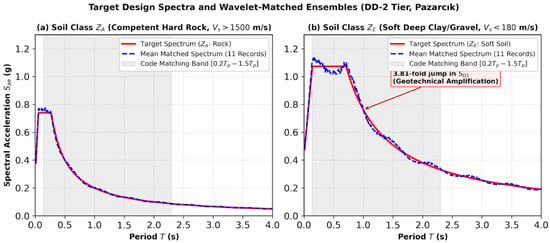
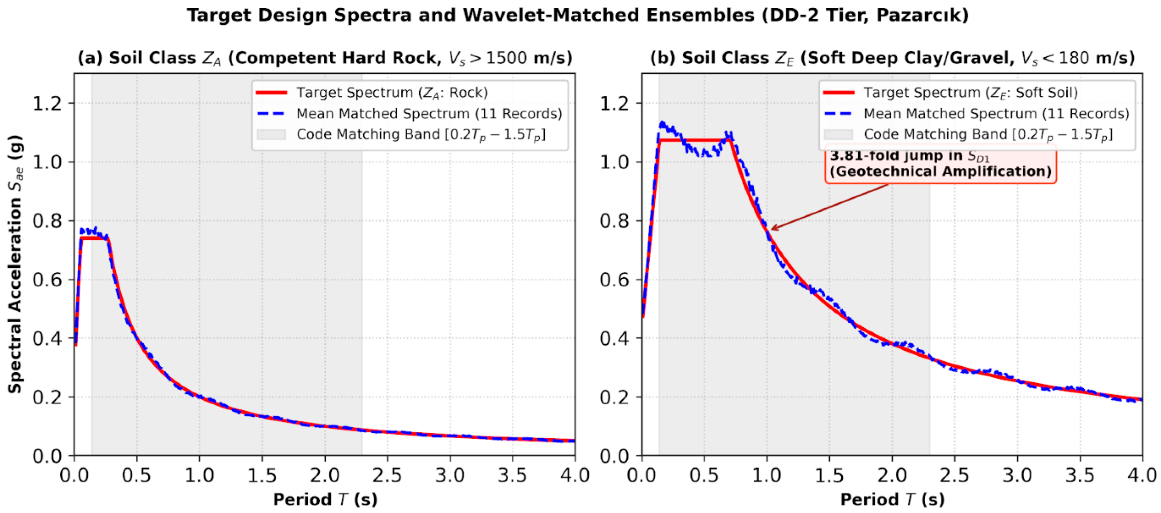
As detailed in Table 2 and Figure 4, while the bedrock ground motion intensities (Ss = 0.925, S1 = 0.250, PGA = 0.386 g) remain identical at the source, the local geotechnical amplification factors alter the resulting surface design spectra. Transitioning from ZA to ZE increases the short-period design spectral coefficient SDS from 0.740 to 1.073 (a 45% increase) and escalates the 1.0-s spectral acceleration parameter SD1 from 0.200 to 0.762—a 3.81-fold jump (Figure 4). This shift concentrates seismic energy in the intermediate-to-long period range (T = 0.7 s − 2.5 s), directly overlapping with the fundamental periods of multi-story steel structures.
Table 2.
Seismic hazard design parameters for the Pazarcık site under DD-2 hazard level across contrasting soil classes.
Figure 4.
Elastic target design spectra according to TBDY-2018 and mean matched response spectra of the 11 real ground motion suites across (a) Soil Class ZA (competent rock) and (b) Soil Class ZE (soft soil), illustrating code matching across the period band [0.2Tp, 1.5Tp] and the 3.81-fold geotechnical amplification in SD1.
3.4. Ground Motion Selection, Suite Compilation, and Wavelet Spectral Matching
To satisfy TBDY-2018 Section 2.5.2 criteria for nonlinear dynamic analysis, a suite of 11 recorded real earthquake ground motion pairs (22 orthogonal horizontal acceleration components) was compiled from the AFAD Turkish Earthquake Data Center System (TADAS) database. Selected records correspond to historic strike-slip and reverse-fault ruptures with moment magnitudes ranging between Mw = 6.1 and Mw = 7.7. The suite includes near-fault station records from the 2023 Pazarcık (Mw7.7) and Elbistan (Mw7.7) earthquakes, the 1999 Gölcük (Mw7.6) and Düzce (Mw7.1) earthquakes, the 2011 Van earthquake (Mw7.0), and the 2020 Sivrice-Elazığ earthquake (Mw6.8). The seismological attributes of the selected records are summarized in Table 3.
Table 3.
Suite of 11 real earthquake ground motion records selected from the AFAD TADAS database for nonlinear dynamic time-history simulations.
Table 3 additionally reports the epicentral distance (Repi, km) for each record, retrieved directly from the AFAD TADAS station/event metadata for the same 11 records. Applying the conventional Repi < 20 km near-field threshold, three of the eleven records fall within the near-field range (Bingöl Merkez, TK 1201, Repi = 11.79 km; and both Sındırgı, TK 1015 records, Repi = 5.36 km and 8.22 km), while the remaining eight records are classified as far-field (Repi = 21.27–66.68 km); this distinction is referenced where relevant when interpreting station-specific response variability in Section 4.
Spectral matching of the acceleration pairs was performed using the continuous wavelet transform algorithm implemented in SeismoMatch. The scaling procedure enforced the TBDY-2018 Section 2.5.3 criterion: the ensemble mean 5% damped elastic response spectrum of the 11 matched record pairs must not fall below 90% of the target design spectrum over the period band from 0.2Tp to 1.5Tp, where Tp denotes the fundamental period of the structure.
To envelop all archetypes (5, 10, and 15 stories with fundamental periods ranging from 0.70 s to 1.53 s), the period matching band was enforced from 0.14 s to 2.30 s. Wavelet adjustments preserve the nonstationary phasing and velocity pulse morphology of the original accelerograms while ensuring that the ensemble average matches the target spectrum. Figure 4 demonstrates the spectral matching across both Soil Class ZA and Soil Class ZE, confirming that the ensemble means satisfy the 90% code floor threshold.
3.5. Nonlinear Direct Integration Dynamic Analysis Methodology
Nonlinear time-history analyses (NL-THA) were conducted in SAP2000 using step-by-step direct integration of the coupled equations of motion given in Equation (6):
where M, C, and K denote the global mass, inherent damping, and tangent stiffness matrices, respectively; FNL(t) represents the restoring force vector from nonlinear damper link elements; and is the ground acceleration vector applied simultaneously in both horizontal orthogonal axes (X + 0.3Y and Y + 0.3X).
Direct numerical integration was executed using the unconditionally stable Newmark average acceleration method with integration parameters γ = 0.50 and β = 0.25. To capture high-frequency response details and prevent numerical divergence, an integration time increment of Δt = 0.01 s was enforced over a duration of 40.0 s (4000 output time steps per ground motion record).
Inherent structural damping was modeled using mass- and stiffness-proportional Rayleigh damping formulated in Equation (7):
C = αmM + βmK
During preparation of this revision, a careful re-examination of the SAP2000 direct-integration time-history load cases revealed that no Rayleigh (mass- and stiffness-proportional) damping had, in fact, been assigned to any of the nonlinear time-history load cases underlying the results reported in Section 3 and Section 4: the Direct Integration damping specification for every case (bare-frame and FVD-equipped alike) was set to “None,” with zero mass- and stiffness-proportional coefficients. Consequently, all reported nonlinear time-history results for the FVD-equipped frames derive their energy dissipation solely from the explicit nonlinear Maxwell link elements described in Section 2 (Equations (3)–(5), together with the small amount of inherent numerical damping associated with the direct-integration scheme; the bare moment-resisting-frame (MFR) baseline cases carry essentially no explicit damping beyond this numerical effect. Geometric nonlinearities, including large-displacement P − Δ second-order moments, were considered at every step to monitor potential lateral drift amplification under long-period ground motions. To quantify the sensitivity of the reported results to this modeling detail, and to verify that the absence of Rayleigh damping does not overstate the contribution of the FVD elements, a supplementary set of analyses was performed in which an explicit 2% Rayleigh damping ratio (assigned to the first two translational modes, using each archetype’s actual periods) was added to the as-analyzed (0% Rayleigh) nonlinear time-history cases for the 5-story (T01) and 15-story (T03) archetypes under Soil Class ZE, X-direction; the results are presented and discussed in Section 4.7.
The adequacy of an 11-record suite for capturing record-to-record variability is examined quantitatively in Section 4 (Table 6): the coefficients of variation obtained for peak base shear, roof displacement, and interstory drift ratio (9–13%) fall within the range commonly associated with a stable ensemble median for a suite meeting the ASCE 7-22 minimum of eleven pairs.
4. Dynamic Results and Discussion
4.1. Modal Eigenvalue Dynamics and Preservation of Elastic Stiffness
Two modeling clarifications are provided here to preempt ambiguity in interpreting the results below. First, the finite-element representation of the FVD assembly follows the Maxwell formulation introduced in Section 2 (Equations (3)–(5)) for nonlinear time-history analysis: a two-node nonlinear link element combines a linear elastic spring of stiffness KA in series with a nonlinear exponential dashpot of coefficient Cd and velocity exponent α, assigned to a single diagonal brace within the central bay of each story. For the free-vibration eigenvalue (modal) analysis reported in this section, however, the link element’s Effective Stiffness and Effective Damping parameters for linear analysis cases were assigned a value of zero, consistent with standard SAP2000 practice for representing a fluid viscous damper as a purely velocity-activated device that contributes no restoring force to a linear, frequency-domain (zero-velocity) eigenvalue solution; the nonlinear stiffness, damping coefficient, and exponent listed above are mobilized only in the nonlinear direct-integration time-history load cases (Section 3.4). This explicit modeling choice, rather than an incidental smallness of KA relative to the frame stiffness, is the direct cause of the identical T1 and T2 values between the MFR and FVD configurations in Table 4, and is disclosed here for full transparency and reproducibility. Second, the primary beam and column members in both the bare (MFR) and damped (FVD) configurations were modeled as linear-elastic frame elements, consistent with the force-based capacity design performed under TBDY-2018 and AISC 360-16 (Section 3.1, Table 1); no lumped-plasticity hinges (e.g., FEMA 356/ASCE 41-type) or distributed fiber-plasticity formulations were assigned to these members. Consequently, statements elsewhere in this paper regarding column yielding or plastic hinge formation are performance-based inferences drawn from the relationship between the computed interstory drift ratios and the damage thresholds established in the literature and code provisions (Section 4.4), rather than direct observations of an explicitly modeled inelastic mechanism; this distinction is revisited as a limitation in the Limitations and Future Work Section.
Table 4.
Free vibration modal periods (T1, T2) of bare (MFR) and damped (FVD) steel frames demonstrating stiffness invariance.
To verify that the supplemental fluid viscous dampers function purely through velocity-activated mechanisms without imposing parasitic storage stiffness, free-vibration eigenvalue analyses were conducted on all structural archetypes in their bare moment-frame configuration (hereafter denoted MFR) and after damper integration (FVD). The fundamental translational periods (T1, T2) across the X and Y orthogonal axes are comparatively listed in Table 4.
As documented in Table 4, the fundamental elastic vibration periods of all three structures remain precisely identical before and after FVD integration. Specifically, the 5-story frame exhibits fundamental translational periods of T1 = 0.70 s and T2 = 0.66 s, the 10-story frame exhibits T1 = 1.53 s and T2 = 1.27 s, and the 15-story frame records T1 = 1.54 s and T2 = 1.50 s under both unbraced and damped conditions (Table 4). This zero-stiffness-penalty characteristic confirms the theoretical Maxwell formulation derived in Section 2 (Equations (3)–(5) and validates the premise established by Makris et al. [16]: through-rod viscous dampers do not add storage stiffness to the superstructure. Consequently, unlike conventional metallic or friction braces that shorten the fundamental period and attract higher pseudo-spectral acceleration demands, FVDs leave the building’s dynamic period unchanged while providing supplemental velocity-dependent energy dissipation [1,7,11].
All modal periods listed in Table 4 were independently verified through eigenvalue (Ritz-vector) modal analysis performed directly in SAP2000 v27.1.0 (Computers and Structures Inc., AISC 360-16), and the reported values are reproduced to within six significant figures of the software output. The near-equivalence of the fundamental period between the 10-story frame (T1 = 1.531 s) and the 15-story frame (T1 = 1.538 s), despite a 50% increase in story count, is not an anomaly but a direct consequence of the capacity-based member sizing summarized in Table 1: the lower five stories of the 15-story frame employ substantially heavier built-up cruciform columns (HEM1000) than the corresponding lower tier of the 10-story frame (HEM700), and this disproportionate increase in lateral stiffness closely offsets the added mass and height, yielding a fundamental-period increase of only 0.5% for five additional stories. This behavior is consistent with drift-controlled (rather than strength-controlled) design of tall steel MRFs under TBDY-2018, in which higher stories require progressively stiffer, not merely stronger, sections to satisfy interstory drift limits.
4.2. Peak Seismic Base Shear Demands and Foundation Attenuation
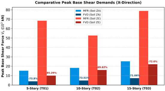
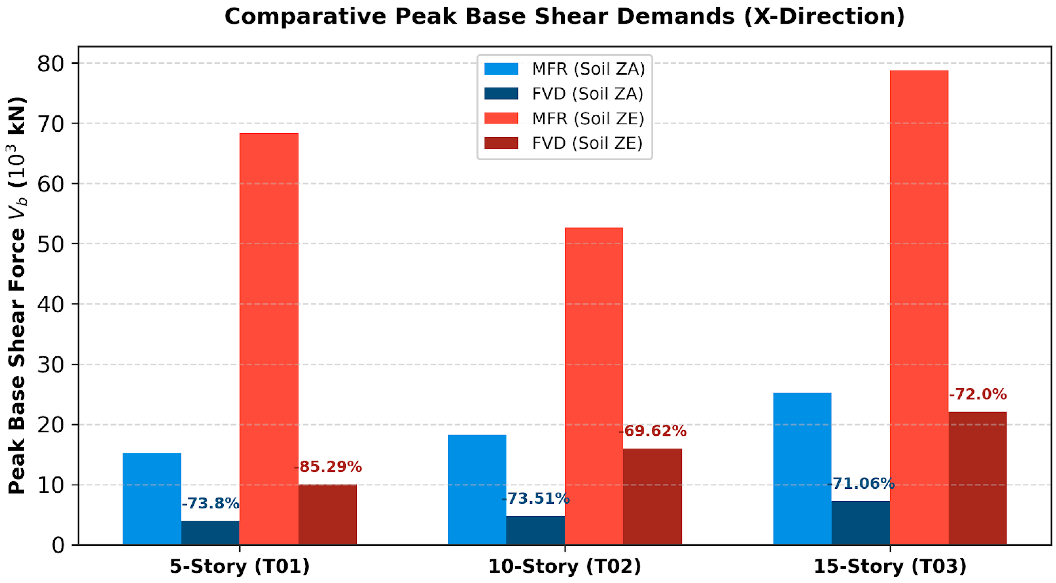
The maximum base shear forces (Vb) extracted from the nonlinear dynamic direct integration analyses under the 11 matched earthquake pairs, along with the corresponding percentage reductions achieved by the FVD systems across both rock (ZA) and soft soil (ZE) strata, are comprehensively summarized in Table 5 and graphically illustrated in Figure 5.
Table 5.
Peak seismic base shear forces (Vb) of bare (MFR) and damped (FVD) steel frames and corresponding attenuation ratios across soil classes ZA and ZE.
Figure 5.
Comparison of peak base shear forces (Vb) for bare (MFR) and damped (FVD) steel frames across soil classes ZA and ZE in the principal earthquake direction (X), showing consistent base shear reductions between 69.62% and 85.29%.
Table 6.
Record-to-record dispersion of peak base shear, peak roof displacement, and peak interstory drift ratio for the 15-story archetype (FVD-equipped) under Soil Class ZE, the most demanding archetype/soil-class combination in the study.
The coefficients of variation (9–13%) across all three response metrics indicate a reasonably stable record-to-record response for this 11-record suite, with the peak interstory drift ratio consistently governing between the 7th and 11th stories across all 11 records and remaining, in every case, well below the TBDY-2018/ASCE 7-22 Life Safety threshold of 1.5%.
The dynamic findings in Table 5 and Figure 5 demonstrate that FVD installations achieve significant base shear reductions across all building archetypes, ranging from 69.10% to 85.29%. The most pronounced mitigation is observed in the 5-story frame under Soil Class ZE in the X direction, where peak base shear drops from 68,345.23 kN in the unbraced frame to 10,055.10 kN in the damped structure—an 85.29% reduction (Table 5 and Figure 5). In the flexible 15-story frame under Soil Class ZE, peak base shear forces of 78,775.96 kN (X-dir) and 77,042.60 kN (Y-dir) are mitigated to 22,055.71 kN (72.00% reduction) and 22,742.80 kN (70.48% reduction), respectively (Table 5).
This consistent 70% to 85% force attenuation stems from the 90-degree phase orthogonality formulated in Equation (2) and illustrated in Figure 1: peak damping resistance acts when the frame passes through zero displacement, whereas maximum column bending moments occur at peak lateral excursion where damping forces drop to zero [1,7,14]. From a structural engineering perspective, this mitigation lowers the overturning moments and base shear transmitted to the foundation, reducing the required footing sizes, mat foundation thicknesses, and pile group demands in soft soils [26,27].
4.3. Lateral Story Displacement Envelopes and Soil Amplification Impact
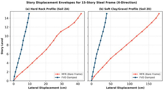
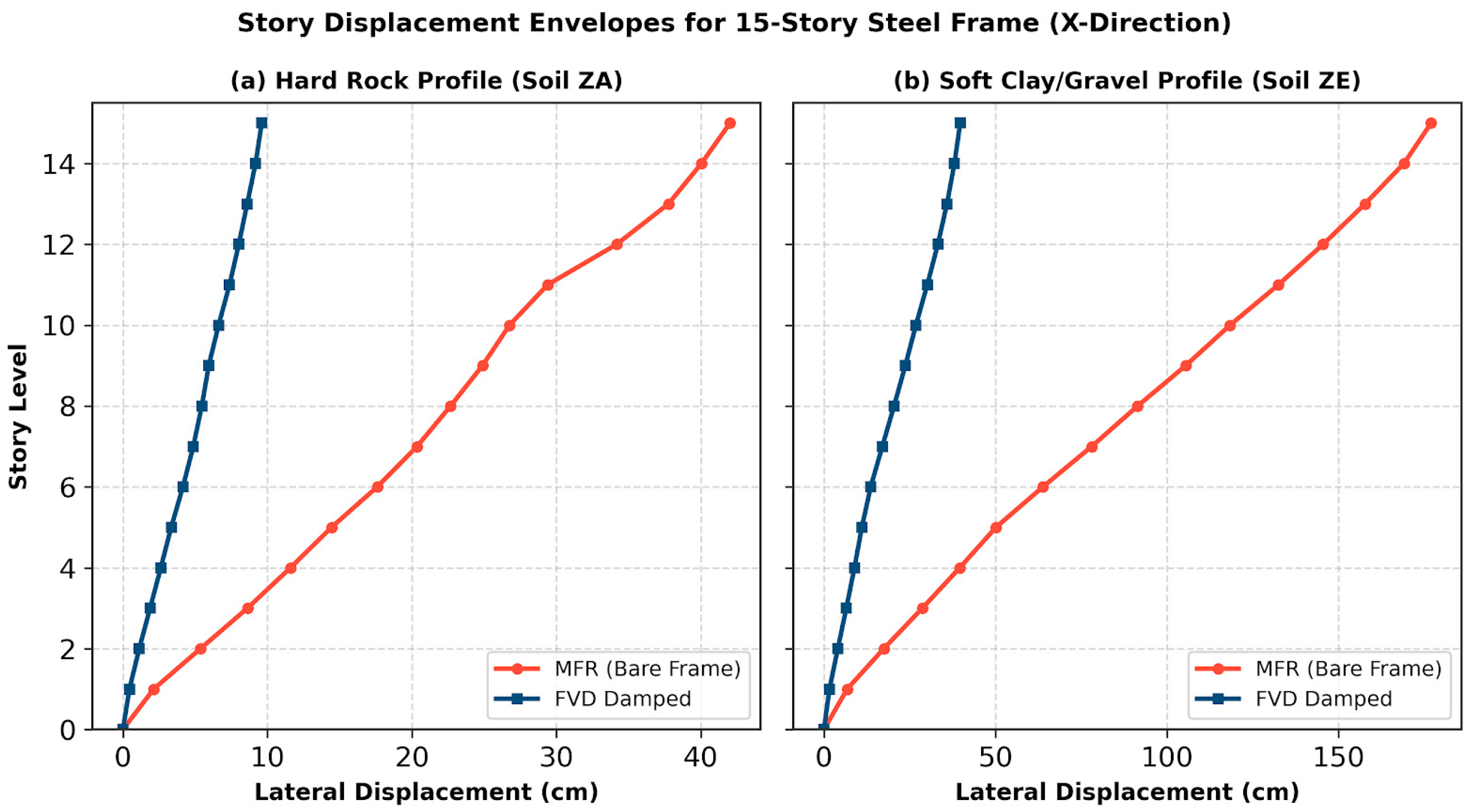
The comparative summary of peak roof displacements recorded across all structural configurations, along with the corresponding mitigation percentages, is presented in Table 7. The height-wise lateral floor displacement envelopes for the 15-story archetype under both Soil Class ZA and Soil Class ZE suites are illustrated in Figure 6.
Table 7.
Peak roof displacement demands and mitigation efficiency achieved via supplemental fluid viscous dampers.
Figure 6.
Comparative height-wise lateral floor displacement envelopes of the 15-story benchmark steel frame (T03) under (a) Soil Class ZA (hard rock) and (b) Soil Class ZE (soft soil) in the principal earthquake direction (X).
The data in Table 7 and Figure 6 highlight the substantial impact of local geotechnical soil amplification. In the unprotected bare frames (MFR), shifting from competent rock (ZA) to soft soil (ZE) causes large displacement increases: the peak roof displacement of the 5-story frame escalates from 6.43 cm to 25.82 cm (X-dir) and from 17.88 cm to 54.38 cm (Y-dir), representing a 3.0- to 4.0-fold amplification (Table 7). In the 10-story frame, roof displacement on Soil ZE reaches 116.79 cm (X-dir) and 131.91 cm (Y-dir) compared to 28.35 cm and 35.51 cm on Soil ZA (Table 7).
For the 15-story frame (Figure 6), the unprotected roof displacement under Soil ZA is 42.03 cm, which increases to 176.94 cm under Soil ZE—a 4.21-fold amplification driven by the 3.81-fold jump in SD1 identified in Table 2 and Figure 4b. Roof displacements of this magnitude on soft soils induce severe second-order P − Δ moments that exceed code-prescribed stability limits [2,4].
When equipped with diagonal FVDs, the displacement profiles across both soil conditions straighten into restrained trajectories (Figure 6). As documented in Table 7, FVD integration reduces the roof displacement of the 15-story structure on Soil ZE from 176.94 cm to 39.71 cm (77.56% reduction in X-dir) and from 168.62 cm to 38.41 cm (77.22% reduction in Y-dir). Similarly, in the 10-story frame on Soil ZE, FVDs decrease the roof displacement from 116.79 cm to 26.04 cm (77.70% reduction) and from 131.91 cm to 25.68 cm (80.53% reduction) (Table 7). These results demonstrate that FVDs remain effective under long-period ground motions amplified by soft soil conditions [26,27].
4.4. Interstory Drift Ratios (IDR) and Performance-Based Collapse Mitigation
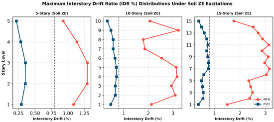
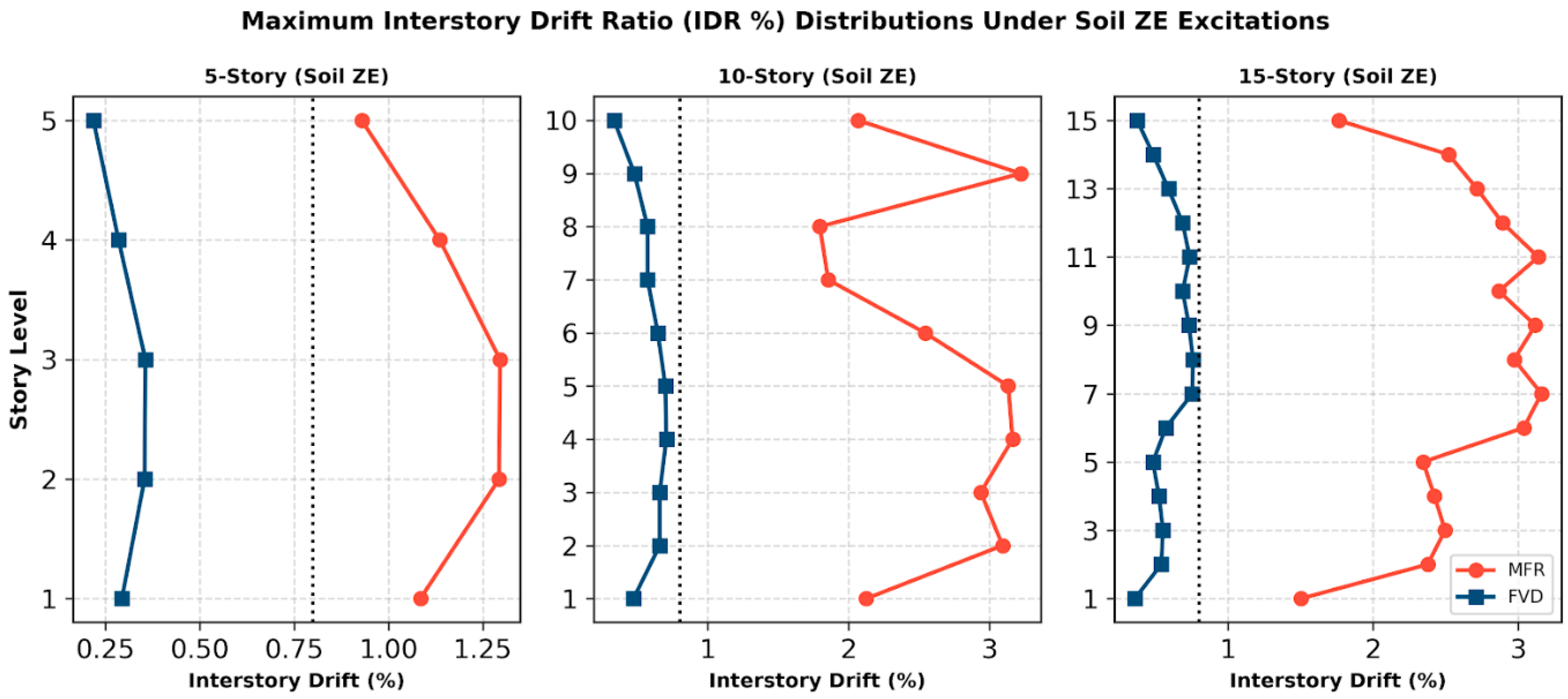
The height-wise distribution of maximum Interstory Drift Ratios (IDR) across all floor levels under the most damaging Soil Class ZE ground motion suites is evaluated in Figure 7. The critical damage-control performance threshold of 0.80% (0.008 rad) specified by TBDY-2018 and ASCE 7-22 for linear/immediate operational performance is included as an explicit benchmark [2,4].
Figure 7.
Maximum Interstory Drift Ratio (IDR %) distributions across all story levels under Soil Class ZE excitations for the 5-, 10-, and 15-story archetypes, demonstrating mitigation below the 0.80% code threshold via FVD integration.
As illustrated in Figure 7, the unbraced bare moment frames (MFR) develop high drift concentrations that exceed code limits:
- •
- In the 5-story frame (T01), unbraced drift reaches 1.29% at Story 2, exceeding the 0.80% immediate occupancy limit and indicating yielding in adjacent beam connections (Figure 7).
- •
- In the 10-story frame (T02), interstory drift demands form a bulging profile along the frame height, peaking at 3.18% at Story 9 and 3.12% at Story 5 (Figure 7). Drift ratios exceeding 3.0% place steel moment frames into the extensive plastic hinge range and indicate collapse risk driven by severe P − Δ effects [5,24].
- •
- In the 15-story archetype (T03), the bare frame records peak IDR demands of 3.16% at Story 7 and 3.13% at Story 11 (Figure 7).
In contrast, the integration of diagonal fluid viscous dampers suppresses interstory drift demands across all elevations (Figure 7). The FVD-equipped frames maintain uniform, nearly linear drift profiles:
By maintaining peak interstory drift ratios below the 0.80% threshold across all stories even under amplified soft-soil ground motions, the FVD systems indicate a low likelihood of flexural plastic hinging in the built-up cruciform columns, minimize residual frame drifts, and protect nonstructural components (architectural facades, glazing, and utility conduits) from damage [1,2,7].
4.5. Damper Force Contribution and Base Shear Phase Relationship
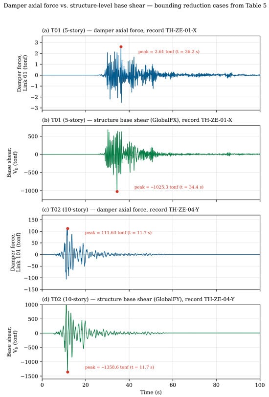
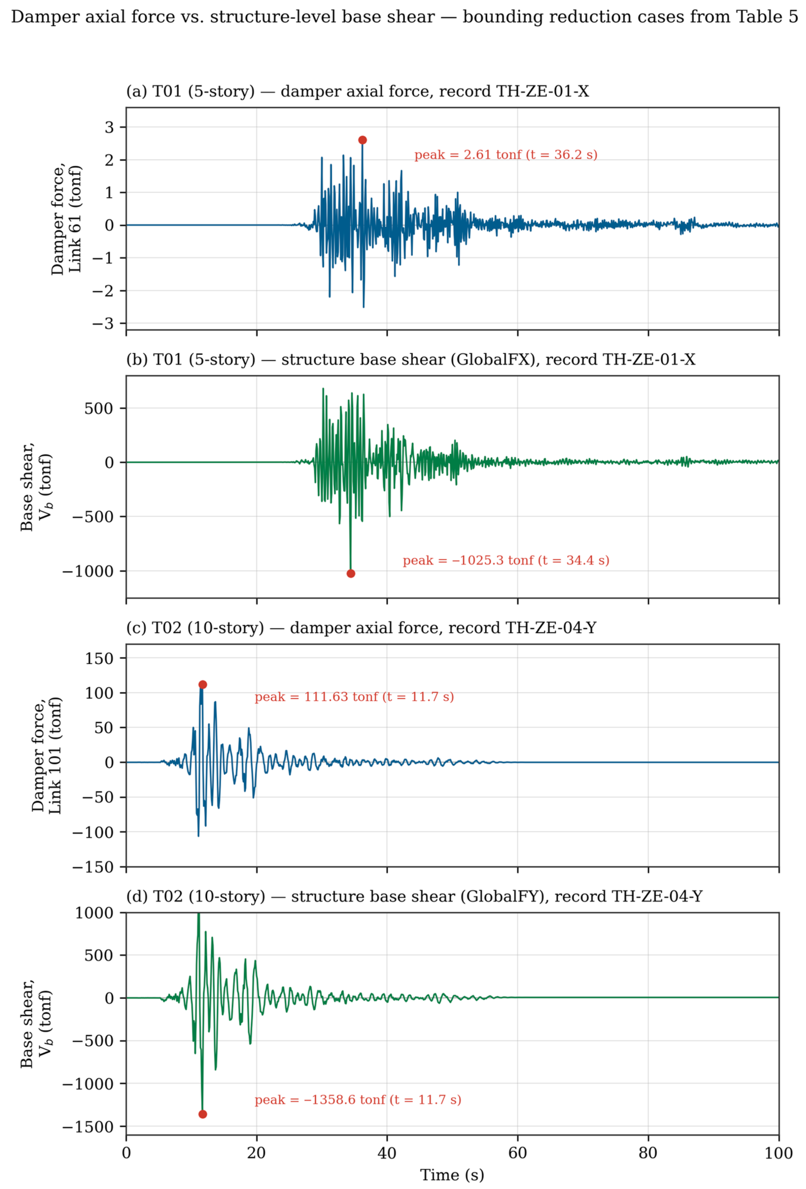
To directly address the reviewer request for a phase-relationship demonstration between the damper force and the frame’s dynamic response, nonlinear time-history (not envelope) output was extracted directly from SAP2000 for the two bounding cases identified in Table 5: the largest attenuation case (5-story archetype T01, Soil Class ZE, X-direction, 85.29% base shear reduction) and the most conservative case (10-story archetype T02, Soil Class ZE, Y-direction, 69.10% reduction). The governing record within each 11-record suite was identified by matching each record’s peak base-shear envelope against the FVD peak reported in Table 5: record TH-ZE-01-X governs the T01/ZE/X case (peak base shear 1025.3 tonf, matching the 10,055.1 kN reported in Table 5 to within rounding), and record TH-ZE-04-Y governs the T02/ZE/Y case (peak base shear 1358.6 tonf, matching the 13,323.4 kN reported in Table 5). For each governing record, the axial force time history of the first-story diagonal FVD link element (Link 61 in T01; Link 101 in T02) was extracted alongside the corresponding global base-reaction time history (step-by-step nonlinear direct-integration output, 0.1 s resolution over the full 100 s record duration).
Figure 8 presents this comparison. In the T01/ZE/X case (Figure 8a,b), the peak damper axial force of 2.61 tonf occurs at t = 36.2 s, while the peak base shear of 1025.3 tonf occurs 1.8 s earlier, at t = 34.4 s; the two peaks are close in time but not coincident, consistent with the general expectation that a purely velocity-proportional damper force need not peak at the same instant as a displacement/inertia-governed base shear. In the T02/ZE/Y case (Figure 8c,d), by contrast, the peak damper force of 111.63 tonf and the peak base shear of 1358.6 tonf occur at the identical time step, t = 11.7 s. The phase relationship between damper force and base shear is therefore not uniform across archetypes and depends on the specific record and structural configuration; a strict 90° (quarter-period) phase lag between the two quantities, sometimes assumed for idealized linear viscous damping under harmonic excitation, is not observed in either case under real, non-stationary earthquake time histories.
Figure 8.
Damper axial force (a,c) and structure-level base shear (b,d) time histories for the largest-reduction case (T01, 5-story, Soil Class ZE, record TH-ZE-01-X; a,b) and the most conservative case (T02, 10-story, Soil Class ZE, record TH-ZE-04-Y; c,d).
It is also observed that the single monitored first-story damper accounts for a much smaller share of the peak base shear in the T01 case (2.61 tonf out of 1025.3 tonf, ≈ 0.25%) than in the T02 case (111.63 tonf out of 1358.6 tonf, ≈ 8.2%). This comparison is reported for a single representative damper element in each archetype’s ground-floor bracing bay and should not be read as the damper’s full contribution to the story shear at that level, since each story is braced by more than one diagonal FVD element and the total damper contribution to story shear is the vector sum of all parallel damper elements at that story, which was not extracted in the present analysis.
This time-history comparison directly addresses the phase-relationship component of the reviewer’s comment using extracted, verified nonlinear analysis output. Two related requests from the same comment, however, remain open at the time of this revision: (i) a full decomposition of total base shear into a frame-shear component and a damper-force horizontal-projection component, which requires aggregating the axial force output of every damper element at a given story, not only the single element examined here, together with the exact brace inclination geometry; and (ii) an independent check of the bare-frame demand-to-capacity ratio against AISC 360-16 member capacities, which requires cross-referencing the original design calculations. Both items require additional post-processing beyond the scope of the present revision and are listed as explicit directions for future work in the Limitations and Future Work Section.
4.6. Sensitivity to the Damper Velocity Exponent (α)
To provide the quantitative comparison requested by Reviewer 2 (Minor Comment 1), the nonlinear damping exponent α of the Taylor D-17120 FVD link property was reduced from 1.0 (the value used throughout Section 3 and Section 4) to 0.4, and the nonlinear time-history suite was re-run in SAP2000 v27.1.0 for the 5-story (T01) and 15-story (T03) archetypes under Soil Class ZE, the governing, most demanding soil class identified in Table 5. T01 was re-run in the X-direction only, already identified as this archetype’s governing shaking direction; T03 was re-run in both the X- and Y-directions, since Table 5 reports comparable base shear demand in both directions for this archetype. Soil Class ZA and the 10-story archetype (T02) were not re-run under α = 0.4; the ZE/T01/T03 subset already spans the softest-soil case together with the most- and least-slender archetypes examined in this study and was judged sufficient to establish the direction and approximate magnitude of the α-sensitivity for the purposes of this revision. A full re-analysis of all six archetype-soil combinations, and of the complete α = 0.3–0.9 range, is identified as a natural extension of the present check in the Limitations and Future Work Section.
Table 8 compares, for each archetype and direction, the peak base shear of the governing (envelope-critical) ground-motion record and the corresponding attenuation from the bare-frame demand under α = 1.0 and α = 0.4.
Table 8.
Comparison of peak base shear demand and attenuation under nonlinear damping exponents α = 1.0 (baseline) and α = 0.4, for the governing (envelope-critical) ground-motion record in each archetype/direction, Soil Class ZE.
As shown in Table 8, reducing α from 1.0 to 0.4 increased the base-shear attenuation effectiveness of the FVD system modestly in every archetype/direction examined: from 85.29% to 87.63% for T01/X, from 72.00% to 75.79% for T03/X, and from 70.48% to 75.11% for T03/Y. This directly answers part (b) of the reviewer’s question for the cases examined: within the tested range, the base shear reduction became somewhat larger, not smaller, under α = 0.4, although this direction of effect is not guaranteed to generalize to other soil classes, exponent values, or the untested 10-story archetype.
A second, more consequential effect emerged in both archetypes: the ground-motion record governing the base-shear envelope changed when α was reduced. For the 5-story archetype, the envelope was governed by record TH-ZE-01-X under α = 1.0 (1025.32 tonf); under α = 0.4 this same record’s peak base shear fell to 755.79 tonf, but a different record, TH-ZE-11-X, became the new envelope-governing case at 861.82 tonf. The reverse pattern occurred in the 15-story archetype: TH-ZE-11-X, the α = 1.0 governing record (2249.06 tonf; Table 6), fell to sixth of eleven records under α = 0.4 (1647.89 tonf), while TH-ZE-08-X—only the second-highest record under α = 1.0 (2004.93 tonf; Table 6)—became governing at 1944.37 tonf. This is real analysis evidence, rather than qualitative reasoning alone, that the record-dependence flagged in our original response to Minor Comment 1 is well founded: not only the magnitude but the identity of the critical record is sensitive to the damping exponent.
Directly addressing part (a) of the reviewer’s question, the peak axial force in the representative first-story damper element (Link 61, T01) was extracted for record TH-ZE-01-X under both exponents. Contrary to the qualitative expectation in our initial analytical response—that a flatter force–velocity curve at high velocity would cap the peak damper force—the peak damper force for this record and element increased from 2.61 tonf (at t = 36.2 s) under α = 1.0 to 4.44 tonf (at t = 34.0 s) under α = 0.4, even as this record’s base shear fell from 1025.32 to 755.79 tonf. This is consistent with the low-velocity steepening of Fd = Cd|v|^α dominating the response of this particular damper element and record: the additional force generated at low-to-moderate relative velocities more than compensated for the capping of force at the velocity peak. The time lag between the damper-force peak and the base-shear peak also narrowed, from 1.8 s under α = 1.0 to 0.4 s under α = 0.4. As this was examined for a single damper element and record, it should not be read as a general rule that peak damper forces increase under α < 1.0 for this system; rather, it demonstrates that the sign of the effect is genuinely record- and element-dependent, exactly as anticipated in our qualitative response to this comment.
Finally, addressing part (c) of the reviewer’s question, peak interstory drift ratios were computed for the new governing records using diaphragm-level nodal displacement envelopes extracted directly from SAP2000 (averaged across all diaphragm joints at each floor, divided by the uniform story height). For the 5-story archetype, peak IDR under α = 0.4 was 0.33% (Story 2) for TH-ZE-01-X and 0.41% (Stories 2 and 3) for the new governing record TH-ZE-11-X, compared with the previously reported 0.36% (Story 3) suite-wide maximum under α = 1.0 (Figure 7). For the 15-story archetype, peak IDR for the new governing record TH-ZE-08-X increased from 0.679% under α = 1.0 (Table 6) to 0.732% under α = 0.4 (Story 11); the Y-direction governing record, TH-ZE-08-Y, reached a comparable 0.744% (Story 11). In both archetypes, drift control performance therefore did not improve in step with the base-shear attenuation in Table 8—for the specific records that became governing under α = 0.4, peak IDR increased modestly relative to the corresponding α = 1.0 values. This qualifies the otherwise favorable base-shear result and answers part (c) of the reviewer’s question: within the tested range, drift control performance was slightly degraded, not improved, for the newly governing records, even though overall base-shear attenuation improved. As a methodological caveat, the α = 1.0 IDR values quoted above for T03 are taken directly from the previously reported per-record values (Table 6) and, for T01, from the previously reported suite maximum (Figure 7), while the α = 0.4 values were computed via the diaphragm-averaging procedure described above; because story-level control-joint definitions were not preserved in the original SAP2000 models, an exactly identical computational method could not be confirmed across both sets of values, so the reported IDR changes (on the order of 0.03–0.06 percentage points) should be read as indicative of direction and order of magnitude rather than as exact figures.
4.7. Sensitivity to an Added Rayleigh Damping Allowance (0% → 2%)
As disclosed in Section 3.5, the nonlinear time-history results reported in Section 3 and Section 4 were obtained with no Rayleigh damping assigned in any load case (0% mass- and stiffness-proportional damping); energy dissipation in the FVD-equipped frames therefore comes entirely from the explicit nonlinear damper link elements. This directly addresses the reviewer’s concern regarding possible double-counting between Rayleigh damping and FVD damping: since no Rayleigh damping was present in the reported analyses, no such overlap could have occurred.
To further examine how a modest, physically motivated inherent-damping allowance would affect the reported attenuation, a supplementary set of nonlinear time-history analyses was run for two archetypes under Soil Class ZE, X-direction, with an explicit 2% Rayleigh damping ratio added to the first two translational modes (using each archetype’s actual periods from Table 4: T1 = 0.697 s and T2 = 0.663 s for the 5-story archetype T01; T1 = 1.538 s and T2 = 1.499 s for the 15-story archetype T03), leaving all other modeling assumptions unchanged. Owing to the time constraints of this revision cycle, this supplementary check was limited to the X-direction response of the T01 and T03 archetypes under Soil Class ZE; the Y-direction, the mid-rise archetype (T02), and the other soil classes were not re-run and are left for future work.
Table 9 compares the governing (largest-magnitude) peak base shear among the 11 ground-motion records for each archetype, together with the resulting attenuation relative to the corresponding bare-frame (MFR) baseline, between the as-analyzed 0% Rayleigh condition and the supplementary 2% Rayleigh condition. In both archetypes, adding 2% Rayleigh damping further reduces the governing peak base shear and modestly increases the attenuation relative to the bare frame: from 85.29% to 86.43% for T01 (5-story), and from 72.00% to 74.98% for T03 (15-story), with the governing ground-motion record shifting in each case. This behavior is monotonic and physically expected—unlike the record-dependent, occasionally unfavorable effect on peak damper force and drift observed for the nonlinear damper exponent sensitivity check in Section 4.6—since adding damping through either mechanism can only add energy-dissipation capacity to the system.
Table 9.
Sensitivity of governing peak FVD base shear to an added 2% Rayleigh damping allowance (Soil Class ZE, X-direction).
Overall, this supplementary check confirms that (i) the base-shear attenuation reported in Section 3 and Section 4 is attributable entirely to the FVD link elements, with no Rayleigh-damping contribution to disentangle or double-count, and (ii) adding a modest inherent-damping allowance on top of the FVD contribution produces a small, monotonic further improvement rather than a distortion of the reported trends. A systematic evaluation of the Y-direction response, the T02 archetype, and the ZA soil class under this same 2% Rayleigh allowance is identified as a direction for future work.
5. Conclusions
This paper presented an investigation into the nonlinear seismic performance of 5-, 10-, and 15-story steel moment-resisting frames equipped with diagonal fluid viscous dampers across contrasting geotechnical soil conditions (ZA hard rock vs. ZE soft soil). Designed in accordance with TBDY-2018 and AISC 360-16 for high-seismicity coordinates on the East Anatolian Fault, the structural archetypes were evaluated under 11 pairs of spectrally matched real acceleration records using direct integration nonlinear time-history analyses. The primary conclusions are:
- Modal Invariance and Zero-Stiffness Confirmation: Modal eigenvalue extractions confirm that diagonal FVDs do not alter the structural natural vibration periods (T1 = 0.70 s, 1.53 s, and 1.53 s for the 5-, 10-, and 15-story archetypes, respectively). Because the supplemental damping is purely velocity-dependent, the systems avoid period-shortening penalties that typically attract higher seismic inertia forces in conventional braced frames [1,7,16].
- Substantial Base Shear Attenuation: FVD integration achieved base shear reductions ranging between 69.10% and 85.29% across all frame heights, soil classes, and shaking directions. The highest reduction (85.29%) occurred in the 5-story frame under Soil Class ZE. This force attenuation lowers column axial-shear forces and foundation overturning moments, offering substantial savings in foundation sizing and pile demands in soft soils [26,27].
- Mitigation of Geotechnical Amplification: Soft soil conditions (ZE) amplify peak roof displacements by up to 4.21-fold in unprotected frames relative to rock sites (ZA) due to a 3.81-fold jump in the long-period spectral parameter SD1. Supplemental FVD damping reduces peak roof displacements by up to 88.05% in low-rise frames and by 77.56% in flexible 15-story frames, mitigating resonance effects.
- Interstory Drift Suppression and Collapse Prevention: In soft-soil environments, unprotected moment frames experience severe drift concentrations (reaching 3.18%) that induce second-order P − Δ collapse mechanisms. The FVD systems consistently restrict peak interstory drift ratios below the 0.80% code threshold across all elevations, indicating a low likelihood of column yielding and protecting nonstructural components [2,5].
- Practical Design Implication: Continuous diagonal FVD configurations provide an effective engineering solution for both new high-performance construction and seismic retrofitting of flexible steel frames located in near-fault zones underlain by soft soil strata.
Limitations and Future Work
The findings of this study should be interpreted within the scope of its modeling assumptions. First, fixed-base conditions were adopted and site effects were represented through code-based amplification of the design spectra; direct-method soil–structure interaction analyses incorporating pile–soil flexibility may modify damper stroke demands, particularly on Soil Class ZE [26,30]. Second, only linear viscous dampers (α = 1.0) in a fixed diagonal central-bay layout were investigated in the main results of Section 3 and Section 4; Section 4.6 provides a first quantitative sensitivity check against α = 0.4 for two of the three archetypes under Soil Class ZE, showing modestly improved base-shear attenuation but a record-dependent, occasionally unfavorable, effect on peak damper force and interstory drift, while a systematic exploration of the full nonlinear exponent range, additional soil classes and archetypes, and optimized non-uniform damper distributions [9,21,22] remains for future work. Third, the primary beam and column members were modeled as linear-elastic frame elements (Section 4.1); as no lumped- or distributed-plasticity hinges were assigned to these members, the reported avoidance of column yielding is a performance-based inference from interstory drift ratios rather than a directly modeled inelastic result, and future work should incorporate explicit hinge modeling to verify member-level behavior under more severe or longer-duration shaking. Fourth, the archetypes are plan-symmetric and regular, so torsionally coupled responses were not addressed. Fifth, the damper-force/base-shear phase-relationship check introduced in Section 4.5 examines a single representative damper element per archetype rather than a full per-story force decomposition, and the reported base shear reductions have not yet been cross-checked against bare-frame member demand-to-capacity ratios under AISC 360-16; both are identified as immediate extensions of the present analysis. Sixth, as disclosed in Section 3.5, no Rayleigh damping was present in the nonlinear time-history analyses underlying Section 3 and Section 4; Section 4.7 reports a supplementary check adding 2% Rayleigh damping for the X-direction response of the T01 and T03 archetypes under Soil Class ZE only, and a systematic re-evaluation covering the Y-direction, the T02 archetype, and the remaining soil classes under this same allowance remains for future work. Future studies will extend the framework to SSI-integrated models, a full parametric sweep of nonlinear damper exponents across all archetypes and soil classes, damper placement optimization, and life-cycle cost and resilience quantification.
Author Contributions
Conceptualization, E.Ç.; Methodology, E.Ç.; Software, E.Ç. and C.Ç.; Validation, E.Ç.; Formal analysis, E.Ç.; Investigation, E.Ç.; Resources, C.Ç.; Data curation, E.Ç. and C.Ç.; Writing—original draft, E.Ç.; Writing—review & editing, C.Ç.; Visualization, E.Ç. and C.Ç.; Project administration, E.Ç.; Funding acquisition, E.Ç. All authors have read and agreed to the published version of the manuscript.
Funding
This research received no external funding.
Data Availability Statement
The original contributions presented in this study are included in the article. Further inquiries can be directed to the corresponding author.
Acknowledgments
The authors thank the Disaster and Emergency Management Presidency (AFAD) for providing the strong-motion records used in this study.
Conflicts of Interest
The authors declare no conflicts of interest.
References
- Soong, T.T.; Dargush, G.F. Passive Energy Dissipation Systems in Structural Engineering; John Wiley & Sons: London, UK, 1997. [Google Scholar]
- AFAD. Turkish Building Earthquake Code (TBDY-2018); Disaster and Emergency Management Presidency: Ankara, Turkey, 2018.
- Tapia-Hernández, E.; Geneş, M.C.; Gülkan, P. Damage assessment and seismic response of steel buildings during the Kahramanmaraş, Turkey earthquakes of February 6, 2023. Earthq. Spectra 2025, 41, 1565–1588. [Google Scholar] [CrossRef] [Scilit]
- ASCE/SEI 7-22; Minimum Design Loads and Associated Criteria for Buildings and Other Structures. American Society of Civil Engineers: Reston, VA, USA, 2022.
- Gupta, A.; Krawinkler, H. Seismic Demands for Performance Evaluation of Steel Moment Resisting Frame Structures; Report No. 132, John A.; Blume Earthquake Engineering Center, Stanford University: Stanford, CA, USA, 1999. [Google Scholar]
- Whittaker, A.S.; Bertero, V.V.; Thompson, C.L.; Alonso, L.J. Seismic testing of steel plate energy dissipation devices. Earthq. Spectra 1991, 7, 563–604. [Google Scholar] [CrossRef] [Scilit]
- Constantinou, M.C.; Symans, M.D. Experimental and Analytical Study of a Fluid viscous Damper Seismic Mitigation System; Report No. NCEER-92-0032; Buffalo: New York, NY, USA, 1992. [Google Scholar]
- Taylor, D.P.; Duflot, P. Fluid Viscous Dampers for Seismic Energy Dissipation; Technical Documentation; Taylor Devices Inc.: North Tonawanda, NY, USA, 2002. [Google Scholar]
- De Domenico, D.; Ricciardi, G.; Takewaki, I. Design strategies of viscous dampers for seismic protection of building structures: A review. Soil Dyn. Earthq. Eng. 2019, 118, 144–165. [Google Scholar] [CrossRef] [Scilit]
- Tsai, K.C.; Chen, H.W.; Hong, C.P.; Su, Y.F. Design of steel triangular plate energy absorbers for seismic-resistant construction. Earthq. Spectra 1993, 9, 505–528. [Google Scholar] [CrossRef] [Scilit]
- Symans, M.D.; Charney, F.A.; Whittaker, A.S.; Constantinou, M.C.; Kircher, C.A.; Johnson, M.W.; McNamara, R.J. Energy dissipation systems for seismic applications: Current practice and recent developments. J. Struct. Eng. 2008, 134, 3–21. [Google Scholar] [CrossRef] [Scilit]
- Pall, A.S.; Marsh, C. Response of friction damped braced frames. J. Struct. Div. ASCE 1982, 108, 1313–1323. [Google Scholar] [CrossRef] [Scilit]
- Mualla, I.H.; Belev, B. Performance of steel frames with a new friction damper device under earthquake excitation. Eng. Struct. 2002, 24, 365–371. [Google Scholar] [CrossRef] [Scilit]
- Constantinou, M.C.; Symans, M.D. Experimental study of seismic response of buildings with supplemental fluid dampers. Struct. Des. Tall Build. 1993, 2, 93–107. [Google Scholar] [CrossRef] [Scilit]
- Seleemah, A.A.; Constantinou, M.C. Investigation of Seismic Response of Buildings with Linear and Non-Linear Fluid Viscous Dampers; Report No. NCEER-97-0004; Buffalo: New York, NY, USA, 1997. [Google Scholar]
- Makris, N.; Constantinou, M.C.; Dargush, G.F. Analytical model of viscoelastic fluid dampers. J. Struct. Eng. 1993, 119, 3310–3325. [Google Scholar] [CrossRef] [Scilit]
- Makris, N.; Constantinou, M.C. Fractional-derivative Maxwell model for viscous dampers. J. Struct. Eng. 1991, 117, 2708–2724. [Google Scholar] [CrossRef] [Scilit]
- Constantinou, M.C.; Tsopelas, P.; Hammel, W.; Sigaher, A.N. Toggle-brace-damper seismic energy dissipation systems. J. Struct. Eng. 2001, 127, 105–112. [Google Scholar] [CrossRef] [Scilit]
- Goel, R.K. Effects of supplemental viscous damping on seismic response of asymmetric-plan systems. Earthq. Eng. Struct. Dyn. 1998, 27, 125–141. [Google Scholar] [CrossRef] [Scilit]
- Lin, W.-H.; Chopra, A.K. Understanding and predicting effects of supplemental viscous damping on seismic response of asymmetric one-storey systems. Earthq. Eng. Struct. Dyn. 2001, 30, 1475–1494. [Google Scholar] [CrossRef] [Scilit]
- Lopez Garcia, D. A simple method for the design of optimal damper configurations in MDOF structures. Earthq. Spectra 2001, 17, 387–398. [Google Scholar] [CrossRef] [Scilit]
- Lopez Garcia, D.; Soong, T.T. Efficiency of a simple approach to damper allocation in MDOF structures. J. Struct. Control 2002, 9, 19–30. [Google Scholar] [CrossRef] [Scilit]
- McNamara, R.J.; Taylor, D.P. Fluid viscous dampers for high-rise buildings. Struct. Des. Tall Spec. Build. 2003, 12, 145–154. [Google Scholar] [CrossRef] [Scilit]
- Lin, W.-H.; Chopra, A.K. Earthquake response of elastic SDF systems with non-linear fluid viscous dampers. Earthq. Eng. Struct. Dyn. 2002, 31, 1623–1642. [Google Scholar] [CrossRef] [Scilit]
- Chalarca, B.; Filiatrault, A.; Perrone, D. Influence of fluid viscous damper stiffness on the floor acceleration response of steel moment-resisting frames under far-field ground motions. J. Earthq. Eng. 2024, 28, 2158–2187. [Google Scholar] [CrossRef] [Scilit]
- Yang, J.; Lu, Z.; Li, P. Large-scale shaking table test on tall buildings with viscous dampers considering pile-soil-structure interaction. Eng. Struct. 2020, 220, 110960. [Google Scholar] [CrossRef] [Scilit]
- Hatipoglu, Y.S.; Duzgun, O.A. Investigation of the effectiveness of viscous dampers connected to adjacent buildings on dynamic behavior under soil-structure interaction effects. Sigma J. Eng. Nat. Sci. 2020, 11, 51–72. [Google Scholar]
- Contay, C.; Çambay, E. Evaluating the influence of fluid viscous dampers on the dynamic behavior of steel frame structures. Constr. Syst. Infrastruct. 2025, 1, 40–53. [Google Scholar] [CrossRef] [Scilit]
- Kramer, S.L. Geotechnical Earthquake Engineering; Prentice Hall: Upper Saddle River, NJ, USA, 1996. [Google Scholar]
- Yang, J.; Li, P.; Jing, H.; Gao, M. Near-fault ground motion influence on the seismic responses of a structure with viscous dampers considering SSI effect. Adv. Civ. Eng. 2021, 2021, 6649124. [Google Scholar] [CrossRef] [Scilit]
- Öztürk, D. The Effect of Viscous Damper Elements on Seismic Behavior of an Existing School Building. Master’s Thesis, Pamukkale University, Denizli, Turkey, 2022. (In Turkish) [Google Scholar]

Disclaimer/Publisher’s Note: The statements, opinions and data contained in all publications are solely those of the individual author(s) and contributor(s) and not of MDPI and/or the editor(s). MDPI and/or the editor(s) disclaim responsibility for any injury to people or property resulting from any ideas, methods, instructions or products referred to in the content. |
© 2026 by the authors. Licensee MDPI, Basel, Switzerland. This article is an open access article distributed under the terms and conditions of the Creative Commons Attribution (CC BY) license.