


Abstract
A large share of the existing building stock in European seismic regions faces a dual critical vulnerability, namely, poor energy performance and high seismic risk, largely due to previous construction practices that ignored modern energy-efficiency standards and earthquake-resistant design. Addressing this urgent need for deep renovation, the Horizon 2020 e-SAFE project aimed to develop innovative retrofit technologies for reinforced concrete-framed buildings that synergistically achieve earthquake safety, energy saving, architectural renewal, economic feasibility, and social welfare. The e-SAFE solutions feature an integrated approach combining novel envelope technologies (prefabricated timber-based panels and three-dimensional steel trusses) and high-performance thermal systems for domestic hot water, space heating, and space cooling. This paper outlines the main multidisciplinary research methodologies—integrating theoretical and experimental investigation, numerical modeling, industrial prototyping, and participatory design—that guided the design and development of these technologies. The full e-SAFE package was subsequently applied to three diverse pilot buildings in Italy and Romania for comprehensive demonstration and validation; the paper discusses the full-scale results, including the validation of structural and energy performance, the effectiveness of the construction process, and the lessons learned from the demonstration activities. These findings highlight both the significant potential of the integrated retrofit package and specific constructive and operational limitations encountered, thereby providing critical data to inform future research and standardization efforts in integrated seismic-energy building renovation.
1. Introduction
The building sector is among the major contributors to global environmental impacts, accounting for a significant share of worldwide energy consumption and greenhouse gas emissions. It is specifically responsible for nearly 37% of global CO2 emissions, with approximately 26% being associated with operational emissions from buildings’ energy use [1]. Improving the energy performance of the existing building stock is therefore recognized as a key priority for accelerating the decarbonization of the building sector. In Europe, this priority has been strongly promoted through the Renovation Wave strategy [2], within the framework of the European Green Deal [3], which aims to achieve climate neutrality by 2050.
At the same time, a large portion of the existing building stock located in EU earthquake-prone countries also exhibits inadequate seismic performance. This vulnerability is primarily related to the age of these buildings, many of which were designed without seismic criteria or according to obsolete seismic regulations [4]. Consequently, improving only the energy efficiency of existing buildings may not be sufficient to ensure long-term resilience and sustainability. In these contexts, integrated energy and seismic renovation is a strategic opportunity to simultaneously achieve climate mitigation objectives, enhance structural safety, and extend the service life of buildings. It has been estimated that integrated renovation strategies could potentially be applied to approximately 60–70% of the European residential building stock [5].
Driven by these challenges, research on integrated retrofit solutions has increased considerably in recent years. Several innovative approaches have been proposed, including exoskeleton-based systems, replacement or strengthening of building envelope components, and combined interventions on roofs and floors [6,7,8]. Among them, renovation approaches implemented from the outside of the building are attracting increasing interest, since they minimize occupants’ disturbance, reduce implementation time and costs, simplify on-site operations, and limit demolition waste production. However, research on this topic is still evolving, since the development of effective integrated retrofit solutions is particularly challenging, due to the need to simultaneously satisfy structural, energy, architectural, technological, and construction-related requirements. Consequently, their development and validation require the integration of complementary expertise and research methodologies in the field of building engineering.
Within this framework, novel integrated retrofit technologies for reinforced concrete-framed (RC-framed) buildings were developed by the authors between 2020 and 2025. This work was conducted as part of the e-SAFE (Energy and Seismic Affordable Renovation Solutions) project, funded by the European Commission under the Horizon 2020 program (Grant Agreement No. 893135) [9]. The proposed technologies specifically consist of prefabricated envelope systems, including timber-based façade panels and three-dimensional (3D) steel trusses, and advanced thermal systems for space heating, space cooling, and domestic hot water (DHW) production. These technologies were developed to concurrently achieve earthquake safety, energy saving, architectural renewal, economic feasibility, and social welfare, while also reducing the environmental impact and invasiveness of the intervention. The innovation of the proposed envelope systems specifically lies in their high level of prefabrication, the design of the seismic components, and the possibility of combining these technologies; this facilitates tailoring different retrofit solutions to each building’s specific features and requirements. Likewise, the thermal systems rely on an innovative concept that combines centralized heat generators and decentralized storage and distribution devices; this allows the system architecture to be tailored to the specific building needs, while also ensuring high energy storage potential.
The multifunctionality of these technologies required the adoption of multidisciplinary research methodologies that synergistically involved different building engineering disciplines, integrating theoretical and experimental investigations, numerical modeling, industrial prototyping, and participatory design processes.
This paper presents the e-SAFE technologies in their final validated configuration and provides a comprehensive framework of the multidisciplinary methodologies that guided their design, prototyping, validation, and full-scale demonstration. The outcomes of the demonstration activities are thus critically examined from an integrated perspective, highlighting potentialities and limitations of the proposed technologies, and outlining future research directions.
The paper is organized as follows: after introducing the proposed technologies (Section 2), it describes the methodologies adopted to assess and validate their structural, energy, architectural, and technological performance (Section 3, Section 4, Section 5 and Section 6); then, the outcomes of their full-scale demonstration in three pilot buildings are reported and discussed (Section 7 and Section 8). Based on the research outcomes, the main opportunities and limitations for the large-scale application of the proposed solutions are highlighted (Section 9).
2. The e-SAFE Integrated Retrofit Technologies
2.1. Integrated Envelope Technologies
The e-SAFE envelope framework comprises three distinct technological solutions: e-CLT, e-PANEL, and e-EXOS. Based on prefabricated timber panels and 3D steel structural trusses applied to a building’s existing perimeter, these technologies form an integrated exterior skin designed to concurrently enhance seismic resilience, thermal efficiency, and architectural quality (Figure 1).
Figure 1.
e-SAFE envelope technologies: e-CLT, e-PANEL and e-EXOS [9].
The e-PANEL is a wooden-framed panel that integrates insulation and finishing materials, as well as new high-performance windows, to both increase the thermal resistance of the envelope components and provide the building with a new architectural image. It is designed to be combined with the e-CLT or e-EXOS, which work to concurrently reduce the seismic vulnerability of the building structure.
The e-CLT is a CLT (Cross-Laminated Timber)-based panel equipped with novel devices for seismic energy dissipation. It aims at enhancing both the seismic and dissipative capacity of the existing structure by exploiting the increased mechanical properties of CLT and the additional energy dissipation source provided by the dampers. The combined effect of these features is the reduction in the drift demand of the structure caused by the earthquake. The e-CLT also integrates insulation and finishing materials to provide the new building envelope with consistent thermal and architectural performance.
Alternatively, the e-EXOS is a structural exoskeleton made of 3D steel trusses. These trusses are designed to force a uniform distribution of the story drifts along the height of the building in the event of an earthquake, reducing the drift demand of the existing structure, and avoiding the activation of the story collapse mechanism. The choice between e-CLT and e-EXOS is driven by the desired level of seismic improvement and depends on the building’s typological features.
The e-SAFE envelope technologies are prefabricated off-site, and are installed by means of mobile lifting equipment, thereby reducing implementation time and occupants’ disturbance. These technologies are also highly customizable in terms of performance and aesthetic appearance according to building boundary conditions (geometric, structural, climatic), owners and users’ needs, and regulatory requirements.
2.2. Features of the Thermal Systems
The e-SAFE thermal system (e-THERM) aims to upgrade the heating, cooling and DHW services in existing buildings, especially when they rely on outdated and inefficient heat generators with hydronic networks that suffer from significant heat losses. Thus, the e-THERM envisages either replacing or integrating the existing heat generators, and utilizing electric heat pumps, which can be partially or fully powered by on-site photovoltaic panels. Additionally, it introduces local thermal storage systems dedicated to domestic hot water, which are installed in each residential unit. This approach reduces heat losses from hydronic networks and empowers users with greater control over their thermal comfort.
The general architecture of the e-THERM system is illustrated in Figure 2, highlighting its main components, which are as follows:
Figure 2.
General architecture of the e-THERM thermal system [9].
- Electric heat pump(s) (EHP): These are used to produce hot water stored in a centralized storage tank. Depending on the specific climatic conditions and the building characteristics, EHPs can be of two types: air-to-water (A2W) or water-to-water (W2W). The W2W heat pumps may be connected to geothermal probes. Heat pumps can either replace existing generators, such as old gas boilers, or be integrated into a district heating system;
- e-TANK: This component is installed in each dwelling and consists of a decentralized storage tank for DHW production. It includes an integrated hydronic module designed to separate the primary water network from the internal network feeding the heating terminals (e.g., radiant panels, fan coils) or the DHW delivery points. This module also contains a control system that manages water temperatures and flow rates, utilizing dedicated valves and energy meters to monitor heating and domestic hot water consumption;
- Integrated photovoltaic system: This system generates renewable electricity from solar sources and includes batteries for energy storage.
In addition to enhancing thermal generation and distribution systems, e-THERM provides new low temperature terminals for space heating and cooling. Additionally, if indoor air quality control is also required, e-THERM can implement mechanical ventilation systems equipped with heat recovery units that are tailored to meet the needs of both residential and public buildings.
3. Seismic Performance of e-CLT and e-EXOS
The seismic performance of the e-CLT and e-EXOS was investigated through an integrated theoretical and experimental approach. Specifically, the structural characterization of the e-CLT was carried out by means of an extensive experimental campaign aimed at characterizing both the cyclic behavior of the dissipative device and its interaction with RC frames under seismic loading. Based on the experimental results, validated numerical models were then developed and used to assess the seismic performance of real-world RC-framed buildings retrofitted with the e-CLT. In parallel, dedicated numerical models were implemented to evaluate the seismic response of the e-EXOS. A detailed description of the experimental validation and numerical modeling adopted for the seismic assessment of both technologies is provided in Section 3.1, Section 3.2 and Section 3.3.
3.1. Development and Experimental Characterization of the e-CLT Friction Connection
The development of the e-CLT system started with the design and experimental characterization of the dissipative connection between the CLT panel and the existing RC structure.
The main innovation of the e-CLT system lies in the use of asymmetric friction connections installed between the CLT panel and the existing RC beams. Each connection consists of two steel profiles clamped together by preloaded high-strength bolts (Figure 3). One of the profiles includes a slotted hole that permits controlled relative sliding once the force transmitted by the CLT panel reaches a predefined activation threshold. Before sliding, the panel contributes to the lateral stiffness of the strengthened structure. After activation, the force transmitted through the connection is approximately limited by frictional resistance, while the relative movement between the steel components produces stable hysteretic energy dissipation. This arrangement was conceived in order to combine the high in-plane stiffness and prefabrication potential of CLT panels with a replaceable and predominantly damage-free dissipative mechanism. The friction devices reduce the seismic displacement demand, while the external installation of the e-CLT elements limits interference with occupants and preserves the existing masonry infills.
Figure 3.
Development of the e-CLT asymmetric friction connection: initial STD-2H configuration (standard with two slotted holes); STD-R configuration (standard with reinforcements); STD-1H configuration (standard with one slotted hole); and ALT-AS configuration (alternative with alignment system) (source: adapted from [10]).
The first experimental phase focused on the cyclic response of the friction device and on the identification of the geometrical parameters governing its behavior. The evolution of the connection, from the initial configuration to the device subsequently used in the full-scale tests, is summarized in Figure 3.
The initial STD-2H configuration was designed to facilitate industrial production, front-side installation, and post-earthquake inspection. However, experimental testing revealed significant bending and twisting deformation of the sliding profile. These effects were mainly attributed to the out-of-plane eccentricity between the friction force and the restraint provided by the connection to the CLT panel, the presence of several bends in the cold-formed steel profiles and the arrangement of the bolts in two non-aligned slotted holes.
The addition of welded steel reinforcements in the STD-R configuration did not eliminate the principal deformation mechanism, because the critical response remained concentrated near the outer bend of the sliding profile. The STD-1H configuration therefore introduced a single, centered, elongated hole containing both preloaded bolts. This arrangement significantly reduced twisting deformation and produced more regular hysteretic loops.
The experiments also demonstrated the importance of the sliding-interface materials and constructive details. Direct steel-to-steel contact resulted in irregular and poorly repeatable hysteretic behavior. In contrast, the introduction of a cap plate and aluminum shim layers produced stable hysteresis loops with an experimentally evaluated friction coefficient of approximately 0.20. Tests performed at different loading velocities did not reveal a significant rate of dependency within the investigated range. Additional information on the experimental campaign is reported in [10].
The connection was subsequently refined into the ALT-AS configuration. This final arrangement was developed to accommodate the relative vertical movements associated with panel rocking, thereby reducing the interaction between the intended horizontal frictional sliding and the vertical kinematics of the CLT panel. Its modular configuration was also designed so that the connection can be installed in successive stages, facilitating the positioning and fastening of the individual components, and reducing the complexity of the on-site assembly process.
The ALT-AS prototype was investigated through cyclic and monotonic tests to evaluate its behavior under repeated sliding. The program examined the influence of the friction-interface material, bolt-preloading procedure, and reuse of the specimens after previous loading cycles.
The test setup, shown in Figure 4a, reproduced the intended horizontal sliding mechanism at progressively increasing displacement amplitudes. The instrumentation separated the specimen deformation from the movement of the test rig and monitored profile rotation and local deformation throughout the loading sequence.
Figure 4.
(a) Laboratory testing setup for the experimental assessment of the ALT-AS friction connection, and (b) representative force–displacement graph.
The connection accommodated large cyclic displacements while maintaining stable and repeatable sliding resistance. The use of aluminum shims helped produce regular hysteretic loops and consistent energy dissipation, as shown in Figure 4b.
Overall, the tests confirmed that the ALT-AS configuration could provide controlled sliding and reliable energy dissipation over a wide range of displacement.
The observations were used to refine the final detailing, assembly sequence, and interface configuration, providing the basis for the improved friction device adopted in the full-scale e-CLT experiments described in Section 3.2.
3.2. Experimental Characterization of the e-CLT System
The seismic performance of the e-CLT system was investigated through quasi-static cyclic tests on full-scale, single-story, single-bay RC frames.
Two identical specimens were realized to represent 1970s Italian construction practice, as characterized by gravity-load-only design, “strong beam–weak column” mechanisms, and insufficient lateral capacity. The frames feature a 4.0 m span and a 3.2 m inter-story height (Figure 5) and were cast using a concrete mix with a mean cubic compressive strength of 26.9 MPa at 28 days.
Figure 5.
(a) Prototype geometry, (b) test setup, and (c) detail of the friction damper.
The experimental campaign began with the characterization of the non-retrofitted control specimens. The bare RC frame was first tested within the elastic range to establish the baseline stiffness of the uncracked structure. Subsequently, a masonry infill was added to the frame to define the reference hysteretic behavior and energy dissipation capacity of the non-ductile infilled system under failure conditions.
The second RC specimen was used to experimentally characterize the e-CLT technology. This frame was infilled and then retrofitted with a 100 mm thick, 5-layer CLT panel, fastened to the top beam with fixing brackets and coupled to the foundation by means of two friction dampers, which were improved with respect to the ALT-AS configuration (see Section 3.1) in order to decouple the vertical movements of the assemblies, decoupling the connection from CLT panel’s rocking. This kinematic optimization prevents parasitic actions on the bolts and local deformations in the steel plates, thereby maintaining system efficiency during cyclic loading.
Finally, to isolate the energy dissipation contribution provided by the friction dampers, a test was conducted on the pre-damaged frame with plastic hinges at the column ends.
To carry out the tests, a 500 kN servo-hydraulic actuator applied horizontal cyclic loading to the top beam. Gravity loads representative of a three-story residential building were simulated by applying a constant vertical force of 250 kN to each column. The foundation was rigidly anchored to the laboratory’s strong floor, and a steel stabilization frame was used to prevent out-of-plane displacements, according to the layout illustrated in Figure 5. The structural response was captured through an extensive instrumentation array, including LVDTs and load cells. Specifically, displacement transducers were positioned on both the top and bottom RC beams to determine the net drift amplitude, enabling the calculation of the inter-story drift percentage. Furthermore, dedicated sensors monitored the relative sliding and kinematics of the friction dampers with respect to the RC frame, providing a detailed assessment of the dissipation device’s operational efficiency.
The tests were performed according to the multi-stage cyclic loading protocol described in Table 1.
Table 1.
Test loading protocol.
The strengthened system successfully achieved its primary design objectives, with the timber panel functioning as a rigid diaphragm throughout all testing phases. The retrofitted configuration reached an initial stiffness of approximately 70 kN/mm, representing a 149% increase compared to the masonry-infilled control specimen. This substantial enhancement in lateral stiffness was accompanied by a significant improvement in capacity, as the system reached a peak base-shear of 263 kN—a 67% increase over the 157 kN recorded for the control specimen. In comparison, the bare frame exhibited a linear elastic response with a much lower initial stiffness (11.4 kN/mm), highlighting the key role of both the infill and the subsequent retrofit in defining the global structural response.
A key aspect of the e-CLT retrofit intervention was the significant enlargement of the hysteretic cycles of the force–displacement curves depicted in Figure 6a, indicating an improvement in the energy dissipation capacity, particularly at high drift levels. This behavior is directly attributable to the activation of the friction dampers, which occurred at approximately 0.5% drift. Once activated, the friction dampers provided a stable and consistent response characterized by hysteretic cycles indicative of pure frictional behavior, dissipating energy through controlled slippage, as demonstrated by the graph in Figure 6b.
Figure 6.
Hysteretic response from experimental tests: (a) comparison between the strengthened and the unstrengthened system—positive range, (b) overall shear force vs. damper sliding.
The cumulative dissipated energy—calculated as the sum of the areas enclosed within each hysteretic loop—confirmed the superior seismic performance of the strengthened system, which dissipated approximately three times the energy of the unstrengthened configuration at 3% drift. This substantial energy dissipative capacity ensured a more stable and less fragile post-peak response, one characterized by a gradual force reduction as drift increased.
Although the concrete strength adopted in the tests was relatively high for some existing buildings, the specimens reproduced typical deficiencies of gravity-load-designed RC frames. The results confirm the effectiveness of the e-CLT strengthening system, although further investigations on frames with lower concrete strengths would help extend the applicability of these results.
The external e-CLT panels may help prevent the outward out-of-plane collapse of masonry infills [11,12,13], reducing the risk of falling debris obstructing emergency access routes. Inward out-of-plane collapse could be prevented through additional flexible connections between infills and RC frames, and without significantly affecting the in-plane seismic response. These potential benefits, not directly investigated in the present study, may be assessed based on the existing literature and appropriate design considerations.
3.3. Assessment of Seismic Response of e-CLT and e-EXOS on a Case Study RC Structure
The evaluation of the seismic performance provided by e-CLT or e-EXOS first required the definition of a case study building. Hence, an RC-framed building was designed considering only gravity loads, so as to be representative of those buildings that were not originally conceived to face seismic forces but were afterwards included within seismic areas. This building was five stories high and had a rectangular plan layout (Figure 7a). Floor decks were assumed to be realized by RC joists arranged along Y-direction connected by a 40 mm thick slab and supported by the four seven bay frames oriented along the X-direction. Only two frames were disposed along the Y-direction, serving to close the perimeter of the plan layout. Cross sections and steel reinforcement of members were sized according to the allowable stress method, as prescribed by the Italian code enforced in 1974 [14]. Columns were designed considering axial force only, while beams were designed to withstand bending moment and shear force. The characteristic compressive cubic strength Rck of the concrete was equal to 25 MPa (corresponding to strength class C20/25), while steel grade Feb38K with a characteristic yield stress fyk = 375 MPa was used for reinforcement. Further details regarding loads on structural elements and minimum requirements on longitudinal and transverse reinforcements can be found in [15].
Figure 7.
Case study building: (a) plan layout, (b) seismic upgrading by e-CLT (top) and e-EXOS (bottom).
The considered RC building was upgraded by applying the e-CLT system or the e-EXOS system. For the sake of brevity, only seismic forces acting along the X-direction were considered. In the first case, following the features of the e-CLT panel tested in [15], e-CLT panels having 100 mm thickness and friction activation force equal to 26 kN were applied at all stories of the perimetral frames (Frames X1 and X4). In particular, considering one of the most common façade configurations, i.e., the one where spans with small (or no) openings are alternated with spans with large openings, e-CLT panels were applied only in the odd spans (those with small or no openings), as shown in Figure 7b [15]. In the second case, four e-EXOS trusses were applied, two at the sides of frame X1 and two at the sides of frame X4 (Figure 7b). Each e-EXOS had 1 m depth (i.e., in-plan distance between adjacent and distant chords), and members were realized by hollow circular cross sections [16].
Since the distribution of lateral stiffness and strength was symmetric with respect to both X- and Y-axis, the structural response to horizontal seismic forces was purely translational. Hence, a 2D numerical model was implemented in OpenSees [17], considering only half of the building, i.e., frames X1 and X2. RC columns and beams were modeled as beamWithHinges elements and the cross section over the length of the plastic hinge was discretized into fibers. The Kent–Scott–Park constitutive law (Concrete01 uniaxialMaterial) [18] and the elastic plastic constitutive law with kinematic hardening (Steel02 uniaxialMaterial) [17] were assigned to the concrete and the steel fibers, respectively. A pair of diagonal trusses was used to model the infill panel. Under the effect of horizontal forces, only the compressive branch was active, and behaved according to the quadrilinear force–displacement relationship proposed by Panagiotakos and Fardis [19] and Celarec et al. [20], modeled by the Pinching4 uniaxialMaterial implemented in OpenSees. Concrete slab at each level was assumed rigid in its own plane and was simulated by means of equalDOF constraints. To consider the P-Δ effect, a leaning column was added to the numerical model. A Rayleigh viscous damping was used and set at 5% for the first and the third mode of vibration. A zeroLength element was added at one end of each beam and worked as a release element to avoid the arising of unexpected axial forces, which typically leads RC beams modeled by fiber elements to display an artificially larger stiffness and strength [21]. In case of e-CLT upgrading, the CLT panel was modeled by means of six equivalent elastic trusses (two vertical trusses, two horizontal trusses and two diagonal trusses), whose axial stiffness was calibrated to provide the same in-plane stiffness of the CLT panel [15]. Friction dampers were simulated by zero-length elements located at the beam-to-column intersection. The behavior of friction dampers in the horizontal direction was described by an elastic–plastic behavior (Steel01 uniaxialMaterial in OpenSees), whose yielding strength represents the friction force necessary to activate the dampers. In the vertical direction, the damper can move freely.
When e-EXOS was applied, the numerical model was updated by adding a plane (2D) equivalent steel truss. Since members of the steel trusses were supposed to remain elastic during the ground motion, elastic “truss” elements were used to model diagonal members, while bottom and upper chords were modeled through “elastic beam-column” or elastic “truss”. To simulate the 3D steel truss by a 2D numerical model, an equivalent cross-section area was assigned to the elements of the numerical model to account for the differences between the number, orientation and length of the members of the real 3D truss and the relevant finite elements of the 2D numerical model [16]. The connection between the truss and decks of the building was supposed to be designed and realized as a conventional rigid link, following the prescription of EC3 [22,23,24] and modeled by constraining the horizontal displacement of each node of the upper chord to that of the adjacent deck by “equalDOF” constraints.
In order to assess (i) the seismic performance of the case study frame and (ii) the beneficial effect provided by the seismic upgrading by e-EXOS or e-CLT on the structural response, incremental nonlinear dynamic analyses (IDA) were performed twice, i.e., considering the numerical model before and after the introduction of the retrofit system. The seismic excitation was simulated by a suite of 30 artificial ground motions compatible with the EC8 elastic spectrum for soil type C and characterized by 5% damping ratio, reference peak ground acceleration (PGA) for soil type A equal to 0.35g and a total duration of 30.5 s. This set of ground motion was scaled from PGA 0.05 g to 0.60 g in steps of 0.05 g.
The seismic performance of the RC frame, before and after the seismic upgrading, was evaluated considering the Near Collapse (NC) limit state as target. The structural response was observed in terms of story drift ratio demand ∆ and demand-to-capacity ratios of columns and beams. The demand-to-capacity ratios were evaluated in terms of chord rotation (ϑ/ϑNC) and shear force (VEd/VRd). The chord rotation capacity of columns ϑNC was assumed to be equal to the ultimate value of chord rotation ϑum according to EC8 [25] for the NC limit state, while the shear strength was calculated according to EC2 [26]. For the given limit state, the maximum values of the response parameters were evaluated for each ground motion and then averaged over the thirty inputs. A more comprehensive evaluation of the seismic performance of the case study was conducted by (i) the construction of fragility curves [27] and (ii) the determination of the mean annual frequency of exceedance λNC of the NC limit state. In particular, the performance is deemed adequate if the PGA corresponding to a 50% probability of exceedance of the relevant limit state is not lower than the targeted value of PGA. The mean annual frequency of exceedance λ of a fixed limit state was calculated assuming a mean seismic hazard function defined by four different probabilities of exceedance PVR (2, 10, 20, and 50%) in a reference period of time of 50 years, and return periods TR of 2475, 475, 225, and 70 years, respectively. The value of PGA corresponding to the return period of 475 years was assumed equal to 0.35g (high seismicity region). Each PGA corresponding to the other return periods TR was determined according to EC8-Part 1 [28] and the corresponding value of was calculated. The four couples of values (, ) were reported in a PGA vs. seismic hazard logarithmic coordinate system and fitted by a quadratic function [29]. The seismic performance was assumed to be suitable if the values of the mean annual frequency of exceedance λ obtained for the NC limit state were lower than the limit value λNC [29].
Figure 8 shows the distribution of the maximum drift demand along the height, averaged over the thirty accelerograms and for increasing seismic input magnitudes (0.05 g, 0.20 g and 0.35 g), which push the structure towards a marked nonlinear response. Before seismic upgrading, the bare frame (red lines) exhibited its largest drift demands in the third story. Particularly under the largest value of PGA (0.35 g), a strong concentration of damage occurred at third and fourth story, leading to a maximum drift demand close to 3%, while the drift demand kept values close to or lower than 1% at other stories. In addition, large values of PGA caused the untimely conclusion of several dynamic analyses, which can be identified as a further index of collapse of the bare RC frame under the related accelerograms. The maximum drift demands obtained from these analyses were not included in the calculation of the average response plotted in the figure. The introduction of the e-CLT system (black line) mainly affected the maximum drift demand, reducing it by 26%. It also tended to regularize the shape of the distribution of drift demand along the height, even though it was not able to provide a fully regular height distribution. Indeed, where the seismic demand was the highest, the displacement demand was large enough to activate the dampers of the e-CLT system, thus leading to a larger dissipative capacity and a reduction in the drift demand. On the other hand, where the drift demand was too low (first and fifth stories), the dampers could not activate, and the e-CLT system did not significantly modify the seismic response of those stories. In the case of seismic upgrading by e-EXOS (gray line), the maximum story drift demand at the fourth story reduced by 40%, even for the largest value of PGA, and a uniform distribution of story drift demand was achieved along the height, thus providing a more seismic regular response along the height.
Figure 8.
Average drift demand distribution (Δ) along the height of the building for PGA: (a) 0.05 g, (b) 0.20 g, and (c) 0.35 g.
Figure 9a shows the fragility curves for the NC limit state of the case study building, with and without seismic upgrading, obtained by aggregating the minimum values of PGA corresponding to both ductile and fragile failure modes, in both beams and columns. When deriving these fragility curves, ground motions that lead to numerical non-convergence are treated as cases in which structural failure occurs. The PGA corresponding to the probability of exceedance of 50% is defined as the PGA capacity and was equal to 0.281 g for the bare RC frame (red line). Since both e-CLT (black line) and e-EXOS (gray line) involved a larger number of stories, and in turn, a larger number of structural members, in the dissipative process, they both improved the overall seismic response of the case study frame (fragility curve shifts towards right). As a consequence, the PGA capacity increased, with respect to that of the unstrengthened building, by up to 30% and 72% in cases of e-CLT and e-EXOS upgrading, respectively. In addition, the ratio of the mean annual frequency of exceedance of NC limit state λ/λreq was determined (Figure 9b), considering ductile failures only (θ), or both ductile and fragile failures (θ + V), and considering failures only in columns or only in beams. For the bare frame, the mean annual frequency of exceedance exceeded the limit value imposed by code for the NC limit state (i.e., the ratio λ/λreq exceeded unity), due to ductile failures in columns. The introduction of e-CLT or e-EXOS systems allowed a drastic reduction in the ratio λ/λreq, which attained values well below unity, without changing the failure modes of structural members.
Figure 9.
Assessment of structural response at the NC limit state: (a) fragility curves, (b) mean annual frequency of exceedance ratio.
Note that the rates of reduction in drift demand, PGA capacity and mean annual frequency of exceedance achieved by the two seismic upgrading systems cannot be straightforwardly compared to each other, as the sizes of the e-CLT and e-EXOS are not based on an optimized design procedure but derived from preliminary design approaches.
The numerical investigation, performed on a representative 1970s gravity-load-designed RC building with concrete class C20/25, confirmed the effectiveness of the e-CLT system in improving seismic performance. Further studies on lower concrete strengths could extend the applicability of these findings.
4. Energy Performance of e-CLT, e-PANEL and e-THERM
4.1. Envelope Performance
The e-CLT and e-PANEL add sustainable low-conductivity materials that increase the thermal resistance of the existing walls. In fact, each panel integrates a layer of thermal insulation; a weatherproof, vapor-open membrane; and the finishing layer (Figure 10). The thermal insulation can be chosen according to the local availability of low-cost biomaterials (e.g., wood fiber, hemp, cork, and cellulose fiber), and its thickness can be set to achieve a thermal transmittance (U-value) that complies with specific national regulations. The membrane protects the inner layers (i.e., fiber cement board, insulation material, CLT panel, etc.) from rainwater, while also allowing transpiration and reducing condensation issues. Then, the finishing layer (e.g., wood–plastic composite, ceramic, stone, porcelain stoneware, glass, rendered fiber boards, or wood) can be chosen according to the users’ aesthetic preferences.
Figure 10.
Materials assembly of e-CLT and e-PANEL (horizontal sections).
Behind the cladding, a scarcely ventilated air cavity helps to reduce building thermal loads in the summer, while also drying possible rainwater infiltration or winter moisture. In the e-PANEL, a second non-ventilated cavity is introduced, to match the overall e-CLT thickness when the two types of panels are used side by side to combine seismic and energy renovation. In this case, the thicknesses of the insulating material applied to the e-CLT and the e-PANEL are not the same; indeed, it is selected in order to ensure similar U-values for the two panels, meaning that the presence of the CLT layer (λ = 0.13 W∙m−1∙K−1) allows for a smaller insulation thickness in the e-CLT.
Now, the U-value of the existing wall can be calculated through the well-known mathematical relation reported in the EN ISO Standard 6946:2017 [30] that embeds the combined effects of thermal radiation, convection and conduction under steady state conditions, and accounts for the various material layers composing the element, their thermo-physical properties (e.g., thermal conductivity λ) and thickness δ, as well as the environmental boundary conditions the element is exposed to (adduction coefficients hoi and hoe), as follows:
Instead, the thermal transmittance of the walls renovated with e-CLT can be calculated through the following relation:
As regards the e-PANEL, since a considerable portion of the overall structure is made of wood studs (Figure 10), the U-value should be calculated as the average value between the fraction of the surface area covered by the studs (y) and the remaining surface (1 − y), covered by thermal insulation:
As a rule, higher y-values occur when the e-PANEL hosts a window, and the building has many windows; on the contrary, lower values occur in panels without any windows embedded. According to the detailed design activity and the implementation experience within the e-SAFE project, an average y = 0.3 is reasonably assumed. The above equations rely on the following assumptions:
- The wooden studs have the same thickness as the insulation layer;
- The wooden studs and the plywood board behind the insulation in the e-PANEL have the same thermal conductivity (λwood);
- The fiber cement board has default thermal conductivity λfib = 0.32 W∙m−1∙K−1;
- The thermal resistance of the scarcely ventilated air gap behind the cladding is RGAP_v = 0.09 m2∙K∙W−1 [30];
- The thermal resistance of the non-ventilated air gap in the e-PANEL is RGAP_nv = 0.18 m2∙K∙W−1 [30];
- The thermal resistance of the waterproof membrane is negligible;
- Metal brackets are simulated as thermal bridges.
The use of Equation (5) implies a certain degree of approximation, as it corresponds to the upper-limit method reported in EN ISO 6946:2017; however, preliminary investigations performed through numerical models based on 2D finite element analysis revealed that it deviates by less than 3% from more accurate calculation methods if applied to the real pilot. The calculations conducted within the e-SAFE project showed that, by adopting a wood fiber layer of 10 cm as insulation, it is possible to ensure U < 0.35 W∙m−2∙K−1 with both e-PANEL and e-CLT, starting from the most common uninsulated wall assemblies (solid brick walls, hollow-brick cavity walls, and concrete walls) [31]. This complies with the minimum requirements for most European countries, except for the coldest regions in Italy and for some countries in Northern Europe (England, Belgium, Germany, the Netherlands, and Norway), where 14–16 cm would be necessary. The proposed retrofit solution also allows for addressing the existing thermal bridges, especially those due to the exposed reinforced concrete beams. Indeed, specific prefabricated panels were conceived to cover the dampers after the e-CLT and e-PANEL installations, while also allowing for their easy inspection and maintenance (Figure 11). These components integrate thermal insulation and are cladded on-site to ensure aesthetic uniformity on the building façade. This approach is very effective in correcting columns and slabs, whose linear thermal transmittance is drastically reduced and almost canceled.
Figure 11.
Materials assembly of e-CLT and e-PANEL, including inter-floor prefabricated covers (vertical sections).
4.2. Thermal Systems
One key feature of the e-THERM solution described in Section 2.2 is its effectiveness in significantly reducing heat losses within the DHW network. Indeed, older buildings often suffer from inadequate thermal insulation in their DHW networks, where a significant amount of heat is lost before the hot water reaches the draw-off points, which results in a reduced efficiency [32]. The e-THERM solution removes the need for centralized domestic hot water storage and the related distribution and recirculation pipe networks, as typically found in large apartment buildings. Instead, it utilizes existing, well-insulated closed-circuit heating networks to provide energy for both zone heating and the local production of DHW by a storage tank (e-TANK system) installed in each dwelling.
The e-TANK is a 140 L storage tank with a flat design (depth of only 300 mm) to reduce the installation space. Its thermal insulation for indoor installation relies on PU foam, with a 20 cm additional vacuum insulating panels (VIP) for outdoor installation. An auxiliary electric heater, with a design electric power of 1.5 kW, is installed to rapidly boost the tank temperature above the set-point temperature, and up to 60 °C if needed, either to fulfill regulations regarding Legionella pneumophila or to heat up the water when the central plant is out of service due to maintenance.
The integrated hydraulic module can be made utilizing different options, depending on the dwelling services to which it must be connected: (i) production of local DHW only, (ii) heating service and production of DHW, or (iii) cooling service and production of DHW. The connection with the existing heating (or cooling) system can be made via a single supply and return pipe, or it can include a manifold, in the case of internal distribution renovation. Consequently, the control system will also adapt to the specific system configuration. The main innovative control strategy focuses on thermally charging the decentralized storage tank (DHW), offering significant advantages over traditional centralized systems. In this general approach, a two-pipe network allows hot water produced in the central thermal plant to be used alternately for heating or for charging DHW in decentralized e-TANK systems. This flexibility is particularly beneficial during periods when simultaneous operation of the supply network is not required, such as during the day, when heating is reduced or turned off.
At the central level, a programmable control system manages the operation of the heat pumps according to building energy demand but also dynamically adjusts the temperature set point of the main storage (55–65 °C) to optimize the direct use of electrical energy from photovoltaic panels. Instead, the e-TANK control strategy utilizes a diverter valve that directs the primary fluid either to the heating circuit or to charge the DHW storage tank. The specific control strategies implemented can vary depending on the building’s energy needs and users’ hot-water demand.
Preliminary numerical simulations were conducted in TRNSYS to evaluate the behavior of the e-TANK under a common DHW withdrawal profile in a residential context with different numbers of occupants. Two scenarios were examined: continuous operating conditions (on-demand charging) and alternating daily periods, which included two or three charging processes per day. Figure 12 illustrates the results, demonstrating how the availability of hot water, based on a particular e-TANK set point configuration, is affected by the actual hot water consumption of individual dwellings. Despite the variations in usage, both control and management solutions are effective in maintaining comfortable conditions for users [33].
Figure 12.
Temperature variations in the e-TANK and the main storage (black line) under different charging scenarios: (a) continuous and (b) twice per day, for three different apartments (with 1, 3 and 5 residents) in a typical day (e-TANK temperature set point = 50 ± 2 °C) [33].
5. Architectural Performance of the e-SAFE Envelope Technologies
The methodology developed within e-SAFE is founded on the acknowledgment of the plurality of actors involved in the transformation of the built environment. The project was not conceived as a linear process moving from expert to user, but as a circular and iterative path where designers, researchers, residents, and local institutions exchange knowledge and construct decisions together. The co-design activities were developed through workshops and related engagement activities. The process comprised three phases: (i) outreach and stakeholder engagement; (ii) co-analysis, including the collection of information on building characteristics, energy use and residents’ needs; and (iii) co-design workshops addressing specific renovation scenarios, such as architectural choices, heating systems and the use of shared spaces. These activities provided structured opportunities for residents, professionals, and other stakeholders to exchange information and discuss design options. Their scope and intensity varied according to the context and available resources; they therefore document a process of engagement and negotiation, rather than by themselves demonstrating consensus or specific social outcomes. Co-design, in this sense, is a model of shared authorship and mutual learning. It establishes a cognitive infrastructure where technical expertise and experiential knowledge coexist and converge [34].
The envelope technologies developed—e-CLT, e-PANEL, and e-EXOS—were therefore interpreted not as isolated products but as a process. They required early and continuous interaction with end-users and embodied an integrated approach capable of counteracting disciplinary fragmentation. Energy renovation, seismic improvement, and architectural transformation were brought back into a unified act of design.
The conceptual framework adopted by e-SAFE was grounded in the reflections of Gillo Dorfles, Georg Simmel, and Michel Foucault [35,36,37]. Dorfles observed that architecture manifests its aesthetic nature within fields of perception, education, and social interaction [35]. Simmel identified space as the arena where forms of social life materialize [36], while Foucault described the city as a woven network of relationships [37]. These contributions led this research to consider beauty not as decoration, but as the condition through which architecture enables coexistence—not as outcome, but as a process.
Four questions were formulated by e-SAFE to function not as discrete queries, but as a discursive path through which the meaning of beauty is gradually defined:
- (i)
- Where does beauty act?—Beauty acts in space, in the tangible dimension where bodies meet. It is the spatial precondition that enables recognition, community, and encounter.
- (ii)
- Who acts with beauty?—Beauty is enacted by social actors, not by buildings themselves. Inhabitants, students, families, and workers are the subjects who produce meaning, transform space, and charge architecture with lived sense.
- (iii)
- How does beauty operate?—It operates through processes of active and receptive transformation, where cooperation and participation shape forms, rhythms, and materials.
- (iv)
- Why pursue beauty?—Not to produce ornaments, but because beauty educates, generates resonance, builds knowledge, and belongs to all. Beauty is not a surplus: it is a necessary principle of design.
To translate this theoretical framework into operative practice, three architectural criteria were developed to guide decision-making:
- (i)
- Variability and Invariability: This criterion concerns the equilibrium between what must remain constant and what can evolve. Invariability is associated with structural and seismic components, which cannot be modified without compromising safety and performance. Variability, instead, concerns elements that allow customization and transformation, such as façade modules, shading devices, and spatial extensions that respond to different modes of inhabitation. By distinguishing these two domains, the project allows architectural freedom to operate where change is possible, while preserving the integrity of the technical decision.
- (ii)
- Incrementability: This criterion defines a project’s capacity to grow over time, according to Alejandro Aravena’s principle [38]. Architecture is imagined not as a finished object but as an open system, capable of accommodating future needs without compromising the coherence of the original intervention. In this sense, renovation becomes the initial phase of a longer architectural trajectory, where inhabitants can progressively adapt and expand their living spaces according to evolving social and economic conditions.
- (iii)
- Recognition of the Dwelling Experience: This criterion affirms that design must emerge from lived practices rather than abstract typologies. Dwelling is not a physical condition but an existential one; it involves habits, gestures, sociability, and the subtle spatial negotiations that structure everyday life.
In the development of the e-SAFE envelope technologies, the criterion of Variability and Invariability ensured structural coherence while enabling localized architectural differentiation. The invariant structural systems ensured seismic safety and energy performance, establishing a reliable technical foundation. At the same time, the variable architectural components—chromatic surfaces, shading devices, and spatial additions—introduced degrees of freedom through which inhabitants could recognize the renewed buildings and resonate with it. Through this balance, the envelope ceases to be a passive boundary and becomes a spatial interface capable of expressing both permanence and change. Incrementability proved particularly relevant in contexts characterized by socio-economic fragility. Instead of imposing fixed architectural solutions, the project introduced scalable spatial possibilities. Buildings were conceived as open frameworks capable of supporting future modifications. The Incrementability strategy acknowledged that housing conditions evolve over time, and that architecture must provide a resilient structure within which such transformations can occur without generating disorder or technical risk. Finally, the Recognition of the Dwelling Experience reoriented the design process toward everyday life. Architectural decisions were informed not only by technical analysis but also by direct interaction with users.
6. Technological Implementation
From a technical perspective, the e-SAFE envelope solutions were engineered with a high degree of prefabrication to enhance the operational efficiency, quality, and environmental sustainability of retrofit procedures. Indeed, manufacturing components off-site reduces on-site installation time and minimizes material waste. This approach also improves construction accuracy, resulting in higher-quality intervention, and improves worksite safety by reducing on-site labor and limiting workers’ exposure to construction-related hazards. To this end, the e-CLT and e-PANEL integrate all functional layers—structural, thermal insulation, weatherproofing and finishing (see Section 4.1)—into pre-assembled panels that offer extensive customization to meet building constraints and user requirements.
The use of fully prefabricated panels to realize the new building envelope requires effective watertightness solutions to prevent water infiltration through the joints between adjacent panels. To address this issue, ethylene-propylene diene monomer (EPDM) bands were used to seal the vertical joints between panels, while the horizontal joints were protected by overlapping the weatherproof membranes integrated into the prefabricated panels. A scarcely ventilated air cavity was also provided into the panels to dry rainwater infiltration and winter moisture.
In accordance with the adopted technical design criteria, the e-SAFE system was prototyped and experimentally tested at SHR in Wageningen (NL) to assess its watertightness, airtightness and wind-load resistance as envelope system, with reference to NEN-EN 12207 [39], NEN-EN 12208 [40] and NEN-EN 12210 [41]. The prototype (Figure 13a,b) simulated a portion of prefabricated envelope made of four panels arranged as follows: one e-CLT and one e-PANEL per story, with a cover panel in between. The stratigraphy used for the panels included wood fiber insulation material and a cladding layer made of porcelain stoneware tiles fixed by means of metal profiles, according to the panel materials assembly reported in Figure 10.
Figure 13.
Prototype of the e-SAFE envelope system: (a) front view; (b) back view.
All tests were successfully completed. The airtightness test resulted in air permeability values of 2.48 m3/h per m2 at 100 Pa and 11.35 m3/h per m2 at 600 Pa for the panels system, corresponding to Class 3 according to NEN-EN 12207 [39]. In terms of watertightness, the panels achieved a performance level of 600 Pa, which is classified as Class 9A under NEN-EN 12208 [40]. Then, the wind-load resistance of the panels was tested under pressure of +2400/-2400 Pa, with Class 4 being achieved under NEN-EN 12210 [41].
These results confirmed the effectiveness of the technical solutions adopted, thereby experimentally validating the technological performance of the new building envelope.
Regarding e-EXOS technology, customized solutions were examined to increase both the property value of the buildings and the appeal of renovation interventions.
Unlike the e-CLT-based intervention, in the e-EXOS-based one, the façade elements that fulfill the energy-related functions of the building envelope are distinct from those with a structural function. The elements are architecturally integrated but remain clearly distinct. In particular, the structural trusses can vary significantly depending on the structural conditions and the position and dimensions of the openings in existing buildings. In the baseline design, the steel trusses feature an equilateral triangular cross-section with side lengths of approximately 1.0 m, offering maximum structural rigidity despite its geometric simplicity.
In functional terms, the steel truss was designed to prevent soft-story collapse mechanisms during seismic events by promoting a uniform distribution of inter-story drifts rather than increasing overall structural stiffness. Consequently, the elements accommodate differential horizontal displacement between stories. Each truss is thus pinned to a new foundation and is fixed at each floor to the building’s decks through connections that constrain the truss node to have the same horizontal displacement of the deck (Figure 14). Provided that these conditions are fulfilled, the geometry of the steel truss may be customized to accommodate distinct architectural solutions. Moreover, as the beam–truss connection conflicts with the configuration of the e-PANEL, the two systems—the truss and the panel—were designed to be integrated.
Figure 14.
Details of e-EXOS truss: (a) new foundation–truss connection (vertical section); (b) RC beam–truss connection.
In accordance with the performance and construction features of the e-SAFE technologies, an operational process was defined to guide their effective implementation in real buildings. This process is based on the synergistic integration of the design, production, and installation phases of the proposed technologies, as well as on the digitalization and industrialization of the renovation process. For this purpose, the design of the intervention is supported by the parametric BIM modeling of all the components of the retrofit solutions. This approach enables fully digital management of the renovation process, while ensuring high levels of replicability according to the building boundary conditions.
The e-SAFE operational process specifically consists of four main stages (Figure 15). First, a scan-to-BIM survey is carried out to develop an accurate digital representation of the outer envelope to be renovated. This stage involves a 3D laser scanning survey of the building façades to accurately detect any geometric irregularities. The acquired point cloud is then processed and converted into editable 3D geometries for integration into the BIM environment. Dedicated point cloud processing methods were developed for this purpose, as detailed in [42].
Figure 15.
e-SAFE operational process.
In the second stage, the BIM model is used to design the retrofit intervention by integrating parametric families of the e-SAFE technologies.
The third stage involves the production and installation of the e-SAFE components. These components are produced in controlled factory conditions, based on the data from the parametric BIM elements, to optimize manufacturing efficiency. The aim is to ensure continuity between the design and construction stages, improving accuracy, quality, and efficiency during implementation.
Finally, in the maintenance stage, the BIM model also remains a central resource after the installation of the e-SAFE components by supporting definition and implementation of maintenance protocols to preserve the long-term performance of the new envelope.
7. The Case Studies
The e-SAFE technologies were demonstrated across the three pilot buildings (Figure 16) located in EU regions with distinct climatic conditions and seismic hazards. All three buildings exhibited structural deficiencies, poor energy performance, and low architectural quality. The proposed solutions were implemented at full scale in one physical pilot project (hereafter referred to as the “real pilot”), whereas in the two remaining cases (“virtual pilots”) they were validated through detailed executive designs.
Figure 16.
e-SAFE pilot buildings: (a) real pilot in Catania (Italy); (b) virtual pilot in Timisoara (Romania); and (c) virtual pilot in Bucharest (Romania).
On the one hand, the real pilot (Figure 16a) is located in the city of Catania, in Southern Italy. It is a five-story apartment block, built in the 1960s, owned by the local public housing authority (IACP, Istituto Autonomo Case Popolari). The building has an RC- framed structure that was designed for gravity loads only, while infill walls are made of two leaves of lightweight hollow concrete blocks (8 cm thick internal leaf and 12 cm thick external one) with an intermediate non-insulated air cavity (9 cm thick). None of the apartments are equipped with heating and cooling systems, except for a few with one or two old split units. Many façade alterations carried out by the inhabitants have significantly changed the original image of the building.
On the other hand, both virtual pilots are located in Romania, in the cities of Timisoara and Bucharest. The first one (Figure 16b) is a three-story school building built in the 1950s. It has an RC-framed structure and non-insulated solid brick infill walls (38 cm thick). The second one (Figure 16c) is a five-story apartment block built in the 1970s. It is made of confined masonry walls with solid bricks (30 cm thick). In both buildings, space heating and domestic hot water are supplied by a municipal district heating network. From an architectural perspective, both buildings exhibit a rather anonymous appearance. The school building in Timisoara is characterized by large windows on all façades, while the residential building in Bucharest features a regular, prismatic, and compact volume, with windows arranged symmetrically and regularly on its main façades.
In the pilot buildings, the e-SAFE retrofit solutions were combined according to the typological characteristics and performance needs of the buildings. Specifically, e-PANEL and e-CLT solutions were used in the real pilot in Catania (Figure 17a). These solutions were notably applied to increase energy and architectural performance, meanwhile demonstrating the construction feasibility of the integrated intervention. Instead, the seismic performance was assessed only at theoretical level, assuming e-CLT panels installed on the short façades, in combination with local strengthening interventions to mitigate some local vulnerabilities in the RC structure. The local strengthening interventions were not implemented, due to budget constraints. These constraints resulted from the considerable increases in material and construction costs in Italy during 2022–2025 driven by the exceptional surge in demand generated by the Italian renovation incentives (so called “Superbonus 110%”) and the war in Ukraine. In the virtual pilots, instead, e-PANELs were combined with the e-EXOS technology (Figure 17b,c), which was implemented in distinct architectural and functional solutions.
Figure 17.
Main plan of the pilot buildings in (a) Catania, (b) Timisoara, and (c) Bucharest, reporting the layout of the e-CLT, e-PANEL and e-EXOS.
In all three pilots, the envelope technologies were also combined with the e-THERM system, which was implemented with different architectures according to the peculiarities of each building. Outdoor installation of the e-TANK in Catania is acceptable because nighttime outdoor temperature in the winter rarely goes below 5 °C, so no freezing risks occur.
The stratigraphy of the panels used in the pilot buildings included the layers described in Figure 10. In particular, for the e-PANEL, the stratigraphy included: (i) 1 cm thickness phenolic plywood; (ii) insulation material selected according to the wall thermal performance required (i.e., 8 cm thickness wood fiber in Catania; 15 cm thickness wood fiber in Timisoara; and 12 cm thickness XPS in Bucharest); (iii) 1.25 cm thickness fiber cement board; (iv) non-ventilated air cavity + 1.25 cm thickness fiber cement board (when e-PANEL is combined with e-CLT); (v) scarcely ventilated air-cavity; and (vi) cladding layer. Conversely, for the e-CLT, it included (i) CLT panel (14 cm thick for the theoretical seismic assessment; 10 cm thick for the on-site application); (ii) 6 cm thickness wood fiber insulation; (iii) 1.25 cm thickness fiber cement board; (iv) scarcely ventilated air-cavity; and (v) cladding layer.
The architectural, seismic, and energy performance provided by the e-SAFE technologies in the pilot buildings, as well as their construction implementation, are discussed in detail in Section 8.
8. Results and Discussion
8.1. Architectural Features
The implementation of the architectural criteria described in Section 5 across the three pilot buildings demonstrated how seismic and energy renovation can evolve into a process of architectural and social regeneration. The new envelopes, indeed, were designed not merely to be technical layers but mediators between structure and community, as well as between material performance and environmental identity.
The main challenge was to transform safety-focused interventions into opportunities for spatial beauty. All three pilot buildings are also located in socio-economically fragile contexts, where the quality of the built environment directly affects the inhabitants’ quality of life. In these contexts, architectural renovation becomes both a technical necessity and an instrument of social care. This design approach was interpreted differently in each pilot building, according to the outcomes of the respective co-design activities.
In the residential building in Catania, residents participated in selecting both the cladding textures of the prefabricated panels and the façade’s chromatic systems. These preferences were gathered through surveys, interviews, focus groups, and visual tools such as physical models, conducted during a series of workshops and meetings at the pilot building site, and involving residents and local stakeholders. Through color, the uniformity of the envelope was not erased but inhabited by diversity (Figure 18a). The façade thus became a collective expression of identity, where individual preferences coexist within a coherent architectural framework.
Figure 18.
Architectural project of the envelope retrofit intervention in the pilot buildings in (a) Catania, (b) Timisoara, and (c) Bucharest.
In the school building in Timisoara, the process involved workshops and public meetings. Students and teachers worked with small physical models of the building, adding elements such as rings, canopies and shelters to the façade (Figure 18b). This tactile approach enhanced spatial awareness and enabled the architectural system to reflect actual patterns of use rather than abstract compositional rules. The co-design phase ended with the proposal of trusses with different geometries (Figure 18b), focusing on their verticality and repeatability, so that they would serve as main distinctive architectural elements.
In the residential building in Bucharest, following the principle of Incrementability, the spontaneous presence of small extensions such as shelves and balconies was interpreted not as disorder but as empirical evidence of residents’ demand for additional living space. A public meeting introduced the principle of Incrementability and demonstrated the possibilities offered by the proposed technology. Residents explored different ways to adapt and extend their living spaces. The design response was therefore articulated through a range of solutions (Figure 18c), from standalone trusses to configurations integrating steel window frames or new balconies, thereby increasing usable outdoor space, extending indoor living areas, and enabling outdoor activities. Residents could select different degrees of increment, transforming the façade from a rigid boundary into a gradient of spatial possibilities.
The above architectural outcomes suggest that, when renovation is conceived as a cooperative process, the resulting architecture does not merely comply with regulatory requirements. The building becomes more efficient, but also more meaningful. It becomes a space that welcomes, expresses identity, and fosters a sense of belonging. Thus, the e-SAFE interventions demonstrated that architectural beauty is not simply produced. It emerges through the shared construction of a renewed way of inhabiting space.
8.2. Seismic Performance
In order to assess the effectiveness of the proposed seismic retrofit solutions and quantify their impacts on the structural response, the seismic performance of each pilot building before and after the seismic retrofitting is here compared. Note that the set of 30 accelerograms adopted to run nonlinear dynamic analysis was different for each pilot building, for the sake of consistency with the location of the relevant building. Artificial accelerograms were preferred to natural ground motion records to achieve a better match with the target spectra. A comparison between the target spectra and the elastic response spectra of the generated ground motions for the three sites under investigation is shown in Figure 19. On average, the coefficient of variation of the spectral accelerations is approximately 0.05 for all three cities.
Figure 19.
Comparison between the target spectra and the elastic response spectrum of each generated ground motion: (a) Catania; (b) Timisoara, and (c) Bucharest.
The numerical models and the seismic assessment methodology already presented in Section 3.3 were adopted for the three pilot buildings and the two retrofit interventions.
First, the seismic performance of the real pilot building located in Catania was assessed before and after the application of the e-CLT system. The results of preliminary nonlinear dynamic analyses highlighted the collapse of the original building, for all 30 accelerograms, with the occurrence of extremely low PGA values. This untimely failure stems from the local collapse of a very short beam (about 75 cm), having a 30 × 50 cm cross-section and small shear reinforcement. Indeed, due to its size, this beam was much stiffer than the others. Consequently, it was subjected to large seismic actions, which caused high levels of plastic deformations and shear forces, leading to a fragile abrupt failure mechanism. In such cases, the e-CLT system was unable to improve the seismic performance of the structure, since the limit state was achieved at low drift levels, when the dampers had not activated yet.
Based on this, a preliminary local intervention was necessary to remove the beam causing the fragile failure, so that larger drift demands could be achieved, and the activation of dampers could take place. Hence, the numerical model of the original frame was updated to simulate this intervention, assuming the removal of the fragile element (beam) and consequently the restoration of the slab. Figure 20 compares the fragility curves of the pilot building in the original configuration (black line) with those of the building with the e-CLT system (gray line). In Figure 20a, the continuous lines refer to a fragility curve determined considering simultaneously ductile and fragile failures, and it overlaps with the dashed lines, which were determined considering only ductile mechanisms. This means that, after the removal of the fragile member, ductile failures were the source of collapse of the building, both before and after the introduction of e-CLT. In Figure 20b, the two fragility curves were obtained considering collapses only in beams or columns, and considering both ductile and fragile failures, and they highlight which members are more critical. In both cases, beams were the critical members, even though the PGA capacity (PGA corresponding to 50% probability of exceedance) increased by about 40% after the e-CLT introduction.
Figure 20.
Fragility curves of pilot building in Catania at the SD limit state: (a) type of failure; (b) type of member leading to failure.
Figure 21 shows the ratio λ/λreq of the mean annual frequency of exceedance (λ) over the required mean annual frequency of exceedance (λreq) at the SD (Significant Damage) limit state. The pilot building in the original configuration (black bar) showed a value of λ/λreq equal to 3.273, which decreased to 1.095 thanks to the introduction of e-CLT system (gray bar). Hence, the e-CLT system characterized by 14 cm thick CLT panels and by an activation force of the damper equal to 26 kN significantly enhanced the seismic performance of the structure. Indeed, the e-CLT system allowed an increase in the PGA capacity of about 40% and a reduction in the ratio of the mean annual frequency of exceedance of 67% at the SD limit state, with respect to the building in its original configuration, and led to values of λ/λreq close to unity.
Figure 21.
Mean annual frequency of pilot building in Catania at the SD limit state before (black bar) and after (gray bar) the introduction of the e-CLT system.
In the case of the pilot building in Bucharest, the seismic response, before and after seismic upgrading by the e-EXOS system, was evaluated in terms of the maximum story drift angle Δ, compared with the story drift angle capacity Δcap. To investigate the effects of e-EXOS on buildings with different ductility capacities for the confined masonry panels, three values of story drift angle capacity were considered (0.5%, 1.0% and 2.0%). For each value of capacity, the demand-to-capacity ratio was calculated for the considered PGA values and accelerograms, the related fragility curves were determined, and the value of PGA capacity was derived in turn. Note that the analysis was run twice, applying the seismic excitation separately in the longitudinal and transversal direction.
The fragility curves obtained for the original building were compared to those of the upgraded building in Figure 22. Plots in column (a) show the response of the building subjected to seismic excitation in the longitudinal direction, while those in column (b) show the response under transversal seismic action. It can be observed that the introduction of the e-EXOS reduced the fragility of the building, regardless of the direction of the seismic excitation. In particular, the beneficial effect of e-EXOS became more significant with the increase in story drift angle capacity.
Figure 22.
Fragility curves of pilot building in Bucharest for different story drift capacities considering the seismic excitation in the (a) longitudinal and (b) transversal directions.
The values of PGA capacity of the original and upgraded buildings, corresponding to the three values of story drift angle capacity, for the two directions of seismic excitation are reported in Table 2, alongside the percent increase in PGA capacity achieved. The PGA capacities showed that the building was more vulnerable in the transversal direction. Moreover, the story drift angle capacity had limited impact on the PGA capacity of the original building, while an increase in story drift angle capacity significantly increased the PGA capacity of the upgraded building. Indeed, the effectiveness of the e-EXOS, which was already significant for Δcap of 0.5%, became even more remarkable for Δcap of 2.0%. In this latter case, the application of e-EXOS doubled the PGA capacity of the building in the longitudinal direction (+98%) and even more in the transversal direction (+130%).
Table 2.
PGA capacity of pilot building in Bucharest, with and without e-EXOS.
The height-wise distribution of the story drift angle demand of the original building is compared to that of the retrofitted structure in Figure 23, considering both directions of seismic excitation. Specifically, for each direction, the maximum value of Δ was calculated for a PGA equal to the PGA capacity of the original building and Δcap = 2.0% (0.166 g and 0.105 g for the longitudinal and transversal directions, respectively) and averaged over the number of accelerograms. The original building tended to develop a localized collapse mechanism at the first story in the longitudinal direction and first/second stories in the transversal direction, where the drift demand resulted to be the largest. Instead, in the retrofitted configuration, the e-EXOS allowed a redistribution of the drift demand in the entire building, thus inhibiting the soft story mechanism, reducing the peak demand along the height of the building and leading to a larger PGA capacity.
Figure 23.
Average story drift angle demand (Δ) of the original and upgraded pilot building in Bucharest, considering seismic excitation in the (a) longitudinal and (b) transversal directions.
The effect of the e-EXOS was assessed also on the pilot building in Timisoara, and the SD limit state was assumed as target. In particular, this case explored the possibility of providing the e-EXOS with an additional source of energy dissipation, including a Buckling Restrained Brace (BRB) at the base of the truss. To consider the effect of the BRB, the numerical model of the truss already described was updated, including the BRB [43].
Figure 24 shows the fragility curves obtained for the original pilot building, considering seismic forces acting along the Y-direction (Figure 24a) and the X-direction (Figure 24b). Fragility curves reported in the first row were obtained by determining, for all structural members, the PGA corresponding to the attainment of the SD limit state, considering ductile mechanisms only (gray plot) or both ductile and fragile mechanisms (black plot). Since the two fragility curves did not overlap, the plot leading to the lowest value of PGA corresponding to the 50% probability of exceedance identified the type of failure mode responsible for the attainment of the target limit state. The second row of plots shows the fragility curves determined separately for columns (black plot) and beams (gray plot), considering both ductile and fragile mechanisms. The plot leading to the lowest PGA corresponding to 50% probability of exceedance identified the structural member that was responsible for the attainment of the target limit state. It can be observed that, when seismic forces acted along the Y-direction, the pilot building in its original configuration suffered fragile failure occurring in beams for a PGA = 0.157 g and did not satisfy the SD limit state. On the other hand, when seismic action was applied along the X-direction, the SD limit state was attained due to fragile failure in beams for a PGA equal to 0.096 g.
Figure 24.
Seismic assessment of original pilot building in Timisoara and the impact of seismic upgrading by e-EXOS: (a) Y-direction, (b) X direction.
The retrofit intervention of the pilot building introduced 12 e-EXOS trusses equipped with BRBs along the longitudinal façades, and two along the transversal façades, to sustain seismic forces acting in the Y- and X-direction, respectively (Figure 25). The location of the trusses was also determined, in accordance with the architectural constraints. Considering the Y-direction, the e-EXOS system enhanced the structural response and the dissipative capacity of the building and increased the PGA capacity to 0.180 g, as shown by the light blue fragility curve in Figure 24a. Despite the remarkable improvement, it was not yet sufficient to fulfill the SD limit state (i.e., PGA equal to 0.20 g corresponding to 50% probability of exceedance, reported as dotted lines in the Figure 24), due to local shear failure that still occurred in some structural members, and that could not be prevented by the e-EXOS system. The complete fulfillment of the SD limit state was obtained by adding an intervention of shear strengthening to one beam of the first floor (Figure 25), which could collapse due to shear failure. This led to a PGA corresponding to 50% probability of exceedance equal to 0.203 g.
Figure 25.
Seismic upgrading of pilot building in Timisoara, in the X- and Y-direction.
As for the X-direction, unfortunately, the effect of the e-EXOS system on the structural response was almost negligible, as shown by the (almost) overlapping of the fragility curve of the original frame (red plot of Figure 24b) with that of the frame with e-EXOS trusses (light blue plot), which attained the SD limit state at 0.097 g. This minor effect in this direction was the consequence of the small number of trusses that could be added due to architectural restraints and the local fragile failures still occurring in some members. The SD limit state was fulfilled when five local interventions were introduced on four beams and one column which suffered from shear failures (Figure 25). Indeed, these interventions allowed the increase in the PGA capacity to 0.236 g, as shown by the blue fragility curve in Figure 24b, thus leading to the fulfillment of the SD limit state.
8.3. Energy Performance
With regard to the energy performance of the e-SAFE envelope technologies, their application to the pilot buildings allowed a drastic reduction in the heat losses through the envelope, as summarized in Table 3 by comparing the thermal transmittance values (U-values) of the outer walls before and after renovation. The renovated walls comply with the current national regulations regarding energy renovation of buildings, in force both in Italy and in Romania [44,45].
Table 3.
U-values before and after e-SAFE renovation. All values are in W·m−2·K−1.
Table 3 reports also the U-values of roof and windows, since e-SAFE aims at the deep renovation of the existing building stock in the EU. As far as roofs are concerned, the lower U-values achieved after renovation were attained through the addition of 12 cm of wood fiber in Timisoara and 12 cm of XPS in Bucharest. No thermal insulation was added to the existing roof structure in Catania, because of budget constraints. On the other hand, the original double-glazed low-emissive windows were kept in all pilot buildings, since their replacement would not justify the extra costs required for installing better-performing fixtures.
Numerical simulations for the real pilot in Catania revealed that the correction of thermal bridges such as columns and inter-floor slabs reduces their contribution to the overall heat losses to less than 3% each, despite their considerable length. However, balcony slabs and window frames keep a considerably high linear thermal transmittance even in the renovated building. If this is a common issue for balconies, even with ETICS insulation, the connection between window frame and external wall might have been further improved by replacing the fixtures and installing them aligned with e-PANEL and e-CLT, which is not done in the final renovation solution. Overall, the thermal bridges determine around 25% of the heat losses by transmission in the current building, but only around 13% in its upgraded version. Numerical simulations also revealed that the metal brackets may locally determine a cold point, but their impact on the overall energy balance of the entire building is negligible.
In terms of thermal systems, the peculiarities of each pilot building led to different applications of the e-THERM concept (see Table 4). In Catania, the focus was on demonstrating the effectiveness of a novel centralized DHW production system coupled with autonomous storage devices in every apartment (e-TANK units). For this reason, two air-to-water heat pumps, each with 13 kW thermal capacity (one serving each side of the building), were installed on the flat roof along with a centralized storage tank (1000 L capacity), fed by the electricity produced by a 6 kWp photovoltaic system coupled with an electric battery (10 kWh storage capacity). Every apartment was instead equipped with an e-TANK unit located on the balcony that could supply backup DHW to the users thanks to an embedded electrical resistance of 1.5 kW.
Table 4.
Summary of the mechanical systems features before and after e-SAFE renovation.
In Timisoara, the existing district heating network provided the opportunity to test the integration of e-THERM within an existing high-temperature water network (i.e., around 80 °C). In this light, the district heating network would be hydraulically disconnected from the existing heating pipe network of the building by inserting a plate heat exchanger. Downstream of the heat exchanger, a pump provides hot water to a central inertial storage tank with an internal coil for DH exchange that acts as a hydraulic separator and increases the thermal inertia of the primary hydronic network. A new air-to-water heat pump with a 110-kW thermal capacity was installed, designed to increase the heating system’s global efficiency and increase the use of Renewable Energy Sources (RES). The heat pump was hydraulically coupled with the district heating, using the same inertial storage tank as above. Finally, two e-TANKs for DHW production in the bathrooms were installed and supplied by either the main storage tank or directly by the district heating.
In the pilot building in Bucharest, the proposed intervention was limited to upgrading the central heating system by integrating the existing district heating system with a new air-to-water heat pump, one partly supplied by photovoltaic energy. Considering the symmetry of the building and the architecture of the current distribution network, the proposed solution considered two similar schemes for the left-hand and right-hand sides of the building, in a similar fashion to that of the pilot building in Catania. Two heat pumps of 15 kW thermal capacity were installed outside, near the entrance of the building at the ground level, while a 16.2 kWp photovoltaic system was installed on the flat roof and produced renewable electricity for the heat pump. As in Timisoara, the district heating network was hydraulically disconnected from the existing heating pipe network by inserting a plate heat exchanger. Downstream of the heat exchanger, a pump provides hot water to an inertial storage tank equipped with an internal coil for district heating exchange and also working as a hydraulic separator between the primary and secondary network and thus ensuring better modulation control and efficiency of the heat pumps. New e-TANK units were installed in each apartment for DHW production, integrated with the hot water supplied by the existing district heating network.
The thermal and energy performance levels of the pilot buildings were then simulated in transient mode in EnergyPlus by considering operational schedules, set point temperatures and internal gains, as prescribed by Italian and Romanian regulations for the energy certification of buildings [44,45]. More details about the simulation assumptions can be found in the public project deliverables [46,47].
The first results concern the heating demand of the pilot buildings before and after e-SAFE renovation and are summarized in Figure 26. Here, the effectiveness of e-PANEL and e-CLT in reducing the heat losses through the envelope is evident: in Catania and Bucharest the heating demand is halved (from 46.8 kWh·m−2·year−1 to 21.2 kWh·m−2·year−1 and from 159.6 kWh·m−2·year−1 to 82.3 kWh·m−2·year−1, respectively), while in the school building in Timisoara the reduction amounts to 42%. Further reductions could have been achieved by also renovating the windows, which—as already discussed—were not replaced, because of reasons relating to cost effectiveness.
Figure 26.
Heating demand before and after the e-SAFE renovation.
Concerning the cooling energy demand, this was appraised only in Catania, given the warmer climate conditions. The results of this analysis reported a reduction in the cooling demand from 20 kWh·m−2·year−1 to around 16 kWh·m−2·year−1, which is equal to about 20% lower energy consumption.
Finally, the non-renewable primary energy consumption for DHW production and space heating service was calculated considering the HVAC features presented above and the non-renewable primary energy conversion factors of Italy and Romania, which for the electricity vector are 1.95 in Italy and 2.00 in Romania, and for the district heating in Romania is 0.92.
In the case of the residential buildings located in Catania and Bucharest, the non-renewable primary energy consumption is cut by about 63%, from 97.7 MWh·year−1 to 36.1 MWh·year−1 in Catania and from 165.5 MWh·year−1 to 61.7 MWh·year−1 in Bucharest, respectively (Figure 27). These noticeable energy savings account also for PV electricity that is self-consumed, which is equal to about 28% in Catania and 18% in Bucharest.
Figure 27.
Non-renewable primary energy consumption before and after the e-SAFE renovation.
As regards the school building in Timisoara, the predicted savings amount to around 52% (from 308.2 MWh·year−1 to 147.9 MWh·year−1).
8.4. Construction Implementation
The demonstration of the e-SAFE technologies in the pilot buildings validated the effective integration of the seismic, energy, architectural, and construction design criteria adopted into a holistic renovation strategy tailored to the boundary conditions of each building. Based on the outcomes of the demonstration, the following construction implementation criteria were established for the e-CLT and e-PANEL systems: (i) sizing the CLT panels and insulation layer to meet structural and thermal performance requirements, respectively; (ii) standardizing panel dimensions to optimize prefabrication and manufacturing processes; (iii) providing joints of at least 20 mm width between adjacent panels to accommodate assembly tolerances and relative displacements induced by seismic events; (iv) providing seismic joints where panels are installed near façade elements that could hinder their correct translation in the event of damper activation—the width of these seismic joints is dimensioned according to the sliding capacity of the dampers; and (v) adopting appropriate waterproofing solutions to prevent water infiltration through panel joints (see Section 6).
In the case of the e-EXOS system, the trusses articulate at ground level via a hinge, which forms the connection to the new foundation. If necessary, anti-instability bracing can be incorporated to increase the efficiency of the trusses and/or reduce their dimensions. The connection between the trusses and the floor slabs is designed and dimensioned according to the thickness of the slabs and the type of perimeter beam.
The demonstration of the e-SAFE technologies made it possible to define the installation procedure for each system, which provides a sequence of controlled on-site operations (Figure 28). As a preliminary step, all façade elements interrupting the vertical continuity of the building envelope (e.g., air-conditioning units, sun-shading devices, verandas, and downpipes) need to be temporarily or permanently removed. Then, a Scan-to-BIM process establishes the geometric and informational baseline for all subsequent activities. This stage specifically involves 3D laser scanning of the building to obtain an accurate 3D point cloud model of its outer envelope. The point cloud accuracy is defined to detect any irregularities in the building envelope that may affect the correct installation of the e-SAFE technologies, such as irregularities in the thickness of the cladding layer or out-of-plumb deviations between the ground and uppermost stories. The acquired point cloud data is then processed in a BIM environment to develop a reliable digital model of the building, which serves to support panels design and installation. In particular, for installation purposes, the digital model is used to define a fictitious reference vertical installation plane for each façade. Accordingly, the gaps between the reference installation plane and the existing façade are compensated for by appropriately dimensioning the steel connections of the prefabricated panels. Based on this approach, the installation of the panels then involves fastening them to the RC beams of the building by proceeding sequentially from the ground story to the top one. The e-CLTs are fastened by means of the friction dampers, while e-PANELs are fastened through angle steel brackets at the top and sliding connectors at the bottom (Figure 28a). Once the panels of two consecutive stories are installed, additional insulating prefabricated panels are installed to cover the non-insulating inter-story gap at the beam level. The cover panels are removable to ensure easy inspection and maintenance of the dampers, which may involve preloading friction bolts that may have loosened after a seismic event or replacing the friction surfaces (i.e., shim layers, cap plate, and alignment component).
Figure 28.
Main installation phases for (a) e-PANEL + e-CLT solutions, and (b) e-PANEL + e-EXOS solutions.
On the other hand, for the installation of the e-EXOS, first, the foundation system is realized. The second step is to prepare the connection between the truss and the building. Then, the e-PANELs are placed, and finally, the steel trusses—which have already been pre-assembled—are installed without the need for scaffolding (Figure 28b).
The installation procedures of the envelope technologies—specifically, e-CLT and e-PANEL—were validated under real operating conditions in the pilot building in Catania.
Specifically, the laser scanner survey of the outer envelope of the pilot building was carried out by the Survey and Representation Laboratory of Kore University of Enna. It was performed using a Leica C10 terrestrial laser scanner (TLS), based on the Time-of-Flight (ToF) measurement principle. Seven scans were acquired at a range setting of 10 mm at 20 m, and registered into a single point cloud, with a mean registration error of 0 mm and a maximum error of approximately 4 mm. The point cloud was then converted into a 3D BIM model in Autodesk Revit [42] to detect all façade irregularities and support the detailed designs of the panels and steel connections.
On-site, the panels were installed using a mechanical arm operated by a team of three workers, who ensured their accurate positioning and alignment. The panels were prefabricated off-site except for the cladding layer, which was applied on-site to prevent damage during transport and handling (Figure 29). A total of 123 prefabricated panels, corresponding to approximately 660 m2 of façade area, were installed at an average installation rate of about 40 m2 per day.
Figure 29.
Demonstration activities in the pilot building in Catania: (a) installation of the e-PANELs, and (b) building at post-intervention state.
The experience gained from the implementation of the e-SAFE technologies in the real-scale pilot thus demonstrated that the combination of off-site prefabrication and controlled on-site assembly improves efficiency by reducing the installation time, while improving its quality and accuracy. At the same time, the rapid and minimally invasive installation process allowed occupants to remain in their homes throughout the intervention, thereby minimizing disruption to their daily lives and enhancing the social acceptability of the renovation process.
9. Conclusions
This paper presented the final outcomes of the research activities carried out as part of the Horizon 2020 e-SAFE project, which aimed at developing innovative integrated retrofit technologies for RC-framed buildings. These technologies consist of prefabricated timber-based panels (e-PANEL and e-CLT) and 3D steel trusses (e-EXOS) applied to the outer envelope of the building to create a new seismic-resistant, energy efficient, and architecturally pleasant skin. The envelope technologies are combined with high-performance technical systems (e-THERM) for hot water, heating, and cooling. In particular, the paper outlined the main multidisciplinary research methodologies that guided the design, prototyping, validation, and full-scale demonstration of these technologies, validating the holistic approach adopted to foster the effective and synergistic integration among the distinct building engineering disciplines involved.
The holistic approach combined theoretical and experimental investigations with numerical modeling, industrial prototyping, and participatory design. Specifically, the analysis of the seismic performance of the e-CLT and e-EXOS combined experimental tests to develop and characterize the behavior of the e-CLT under cyclic loading, and numerical nonlinear dynamic analysis to assess the seismic response of the e-CLT and e-EXOS on RC-framed structures. The experimental and numerical results confirm the effectiveness of the e-CLT system for existing gravity-load-designed RC frames, despite the slightly higher concrete strength adopted in the experimental specimens. Furthermore, the external CLT panels may contribute to preventing the outward out-of-plane collapse of masonry infills, while additional flexible connections could provide restraint against inward collapse. These additional out-of-plane benefits deserve further investigation. The analysis of the energy performance of the e-CLT and e-PANEL involved theoretical investigations and dynamic thermal simulations to assess their impacts in terms of improvement of the thermal performance of the building envelope as well as reduction in the building energy needs. In parallel, the architectural and construction analysis provided the framework for integrating participatory co-design, industrial prototyping, and a BIM-based operational process. Participatory co-design guided the development of the proposed technologies according to both performance requirements and stakeholders’ needs, while industrial prototyping experimentally validated the technological performance of the new prefabricated building envelope, together with its manufacturing and assembly processes. The BIM-based operational process supported integrated design and the effective implementation of the proposed technologies, fostering their replicability and facilitating their transfer into professional practice.
The e-SAFE technologies were demonstrated in three pilot buildings located in EU countries with distinct climatic conditions and seismic hazard—i.e., Catania (Italy), Timisoara (Romania) and Bucharest (Romania)—validating their feasibility and effectiveness.
In the building in Catania, the application of the e-CLT proved to be able to increase the dissipative capacity of the existing structure and consequently reduce its seismic demand, leading to an increase in PGA capacity of around 50% and a reduction in the ratio of the mean annual frequency of exceedance of 50% at the NC limit state. These results were achieved by simulating preliminary local strengthening interventions to mitigate some local vulnerabilities in the RC structure.
In the buildings in Timisoara and Bucharest, instead, the e-EXOS redistributed the drift demand within the entire building, inhibiting the soft story mechanism, and increasing the PGA capacity.
As regards energy performance, the e-SAFE retrofit solutions enabled noticeable energy savings in all three pilot buildings, demonstrating the effectiveness of e-PANEL and e-CLT in reducing the heat losses through the building envelope and that of e-THERM in enhancing the performance of HVAC and DHW systems. Indeed, the e-SAFE solutions reduced the current energy need for space heating by 50% in the buildings in Catania and Bucharest, while the non-renewable primary energy use was reduced by around 63% compared to the current state of the building. As regards the building in Timisoara, the savings in space heating energy demand and non-renewable primary energy amounted to 42% and 52%, respectively. These outcomes rely on dynamic energy simulations and necessitate further verification through monitoring activities.
From an architectural and construction perspective, the proposed technologies demonstrated their architectural flexibility and confirmed the effectiveness of integrating off-site prefabrication with controlled on-site assembly. This approach enhanced the efficiency of the intervention by reducing installation time while improving construction quality and assembly accuracy. At the same time, the high level of prefabrication of the e-SAFE solutions requires skilled labor for their installation, which involves the accurate positioning and alignment of the system components.
The participatory design also transformed the renovation process into an opportunity for urban regeneration, fostering inhabitants’ sense of belonging and demonstrating that safety and energy efficiency can be successfully combined with architectural and social quality.
The outcomes of the multidisciplinary research activities thus enabled definition of the applicability criteria and main limitations for the application of the e-SAFE technologies, identifying the boundary conditions under which the proposed technologies can be effectively implemented. Overall, the main target buildings for the application of the e-SAFE technologies are medium-rise, multi-story RC-framed buildings characterized by poor energy and seismic performance. These solutions are particularly effective when the RC members of the existing structure exhibit good ductility, low stiffness, and high shear capacity to prevent shear mechanisms prior to its members’ yielding. Conversely, local vulnerabilities in the RC members can compromise the overall effectiveness of the e-SAFE retrofit solution. In such cases, adequate seismic performance can be achieved only by combining the e-CLT and/or e-EXOS systems with conventional strengthening measures (e.g., fiber-reinforced polymer or RC jacketing).
More specifically, the e-CLT system is suitable for buildings with sufficient windowless outer wall surfaces to accommodate the structural panels required to achieve the desired level of seismic upgrading. Conversely, buildings with extensive glazed areas may be less suitable for e-CLT implementation. In such cases, e-EXOS may offer a viable alternative. The e-EXOS technology, however, requires sufficient space around the building perimeter, additional foundations, and modifications to the original façade configuration. Therefore, it is most suitable for buildings with adequate surrounding space and without urban or architectural constraints that would prevent the installation of external elements altering the original façade appearance. Accordingly, buildings featuring both extensive glazed areas and limited space around their perimeter may be unsuitable for the application of e-SAFE solutions.
The identified boundary conditions provide a rational basis for the effective implementation and large-scale adoption of these technologies, ensuring that the selected retrofit solution is consistent with the structural and architectural features of the existing building and the expected performance improvements.
Future research should focus on the long-term monitoring of the energy performance of the proposed technologies and assess their in-service behavior. Further investigations should also explore the applicability of the e-SAFE solutions to a broader range of building typologies and boundary conditions, supporting the optimization and replicability of these solutions in large-scale application.
Author Contributions
Conceptualization, S.D., G.E., G.M. and E.M.M.; methodology and validation: A.A., F.B. (Francesco Boggian) and R.T. for the experimental characterization of the damper, C.M., A.M. and L.P. for the experimental characterization of the e-CLT, F.B. (Francesca Barbagallo), M.B. and E.M.M. for the assessment of seismic response of e-CLT and e-EXOS on RC structures, V.C. and G.E. for energy-efficiency issues on e-CLT and e-PANEL, G.S. for energy-efficiency issues on e-THERM, S.D. and G.M.N. for architectural issues, and S.M.C., A.F., L.G., G.M., G.R. and C.T. for construction issues; investigation and data curation for the case studies: F.B. (Francesca Barbagallo), M.B. and E.M.M. for structural issues, V.C., G.E. and G.S. for energy-efficiency issues, S.D. and G.M.N. for architectural issues, and L.G., G.M., G.R. and C.T. for construction issues; writing—original draft preparation: all authors; writing—review and editing: C.T., G.E. and G.M.; project administration and funding acquisition: G.M. All authors have read and agreed to the published version of the manuscript.
Funding
The work of this paper was accomplished within the framework of the “Energy and seismic affordable renovation solutions” (e-SAFE) project, which has received funding from the European Union’s Horizon 2020 research and innovation program under grant agreement No. 893135. Neither the Executive Agency for Small-and-Medium-sized Enterprises (EASME) nor the European Commission is in any way responsible for any use that may be made of the information it contains.
Data Availability Statement
Data will be made available on request.
Acknowledgments
The authors gratefully acknowledge the non-academic partners who contributed to the development of the e-SAFE project: Moverim Consulting Srl; Istituto Autonomo Case Popolari di Catania; Engineering Ingegneria Informatica S.p.A.; Deloitte Limited; Building Performance Institute Europe ASBL; Pink GmbH; Sampas Bilisim Ve Iletisim Sistemleri Sanayi Ve Ticaret A.S.; Salfo and Associates SA; and Timmerfabriek Webo BV. The authors also extend their special thanks to Laura Saija, Giulia Li Destri Nicosia, and Venera Pavone for their contributions to the co-design activities and the development of local platforms in Catania, Timisoara, and Bucharest—the cities in which the e-SAFE pilot buildings are located. Finally, the authors thank Dario Luigi Distefano, Gabriele Fichera, and Veronica Guardo for their valuable contributions to the development of the e-SAFE retrofit solutions.
Conflicts of Interest
The authors declare no conflicts of interest.
References
- United Nations Environment Programme. Global Status Report for Buildings and Construction 2025–2026: As Climate Risks Rise and Cities Grow, We Must Rethink How We Build to Create Better Lives for All; United Nations Environment Programme: Washington, DC, USA, 2026. [Google Scholar] [CrossRef] [Scilit] [PubMed]
- European Commission. A Renovation Wave for Europe: Greening Our Buildings, Creating Jobs, Improving Lives; COM(2020) 662 final; European Commission: Brussels, Belgium, 2020. [Google Scholar]
- European Commission. The European Green Deal; COM(2019) 640 final; European Commission: Brussels, Belgium, 2019. [Google Scholar]
- Palermo, V.; Tsionis, G.; Sousa, M.L. Building Stock Inventory to Assess Seismic Vulnerability Across Europe; EUR 29257 EN; Publications Office of the European Union: Luxembourg, 2018; PUBSY No 112031. [Google Scholar] [CrossRef]
- Romano, E.; Negro, P.; Santarsiero, G.; Masi, A.; Butenweg, C. Identification of European Buildings Most Needing Seismic and Energy Retrofit with a Focus on the Italian Context—REEBUILD: Integrated Techniques for the Seismic Strengthening and Energy Efficiency of Existing Buildings; Publications Office of the European Union: Luxembourg, 2023; JRC130997. [Google Scholar] [CrossRef] [PubMed]
- Pohoryles, D.A.; Bournas, D.A.; Da Porto, F.; Caprino, A.; Santarsiero, G.; Triantafillou, T. Integrated seismic and energy retrofitting of existing buildings: A state-of-the-art review. J. Build. Eng. 2022, 61, 105274. [Google Scholar] [CrossRef] [Scilit]
- Filippou, C.A.; Oliveira, D.V.; Dionysios, B.A.; Lourenço, P.B. Integrated Seismic and energy interventions on building envelopes using advanced composite and prefabricated panels: A state-of-the-art review. Dev. Built Environ. 2026, 27, 100940. [Google Scholar] [CrossRef] [Scilit]
- Calò, S.; Cascardi, A.; Leto, M.D.; Mendola, L.L.; Aiello, M.A. Synergistic approaches to structural and thermal retrofitting via external envelopes for existing buildings: A state-of-knowledge. Energy Build. 2026, 367, 117709. [Google Scholar] [CrossRef] [Scilit]
- Available online: https://esafe-buildings.eu/en/ (accessed on 15 June 2026).
- Boggian, F.; Tardo, C.; Aloisio, A.; Marino, E.M.; Tomasi, R. Experimental cyclic response of a novel friction connection for seismic retrofitting of RC buildings with CLT panels. J. Struct. Eng. 2022, 148, 04022040. [Google Scholar] [CrossRef] [Scilit]
- De Luca, F.; Verderame, G.M.; Gómez-Martínez, F.; Pérez-García, A. The structural role played by masonry infills on RC building performances after the 2011 Lorca, Spain, earthquake. Bull. Earthq. Eng. 2014, 12, 1999–2026. [Google Scholar] [CrossRef] [Scilit]
- Furtado, A.; Rodrigues, H.; Arede, A.; Varum, H. Influence of the in plane and out-of-plane masonry infill walls’ interaction in the structural response of RC buildings. Procedia Eng. 2015, 114, 722–729. [Google Scholar] [CrossRef] [Scilit]
- Ricci, P.; Di Domenico, M.; Verderame, G.M. Empirical-based out-of-plane URM infill wall model accounting for the interaction with in-plane demand. Earthq. Eng. Struct. Dyn. 2017, 47, 802–827. [Google Scholar] [CrossRef] [Scilit]
- Ministry of Public Works. Technical Regulations for Constructions with Reinforced Concrete, Prestressed Concrete and Steel Structure; Ministry Decree, 30/05/1974; Gazzetta Ufficiale Serie generale; Ministry of Public Works: Roma, Italy, 1974. [Google Scholar]
- Barbagallo, F.; Licciardello, E.; Marino, E.M.; Mazzotti, C.; Pozza, L. A dissipative CLT based seismic upgrading system for RC framed structures: Experimental characterization, numerical modelling and design guidelines. Earthq. Eng. Struct. Dyn. 2025, 54, 1775–1796. [Google Scholar] [CrossRef] [Scilit]
- Barbagallo, F.; Bosco, M.; Leni, W.; Licciardello, E.; Marino, E.M.; Spinella, N. A steel exoskeleton for regularization of the seismic response in elevation of existing RC framed structures. In Proceedings of the 10th European Workshop on the Seismic Behavior of Irregular and Complex Structures—10th EWICS, Catania, Italy, 5–6 October 2023. [Google Scholar]
- Mazzoni, S.; McKenna, F.; Scott, M.H.; Fenves, G.L. OpenSees command language manual. Pac. Earthq. Eng. Res. Cent. 2006, 264, 137–158. [Google Scholar]
- Kent, D.C.; Park, R. Flexural members with confined concrete. J. Struct. Div. ASCE 1971, 97, ST7. [Google Scholar] [CrossRef] [Scilit]
- Panagiotakos, T.B.; Fardis, M.N. Seismic response of infilled RC frame structures. In Proceedings of the 11th World Conference on Earthquake Engineering, Acapulco, Mexico, 24–29 June 1996; Available online: https://www.iitk.ac.in/nicee/wcee/article/11_225.PDF (accessed on 17 June 2026).
- Celarec, D.; Ricci, P.; Dolšek, M. The sensitivity of seismic response parameters to the uncertain modelling variables of ma-sonry-infilled reinforced concrete frames. Eng. Struct. 2012, 35, 165–177. [Google Scholar] [CrossRef] [Scilit]
- Barbagallo, F.; Bosco, M.; Marino, E.M.; Rossi, P.P. On the fibre modelling of beams in RC framed buildings with rigid dia-phragm. Bull. Earthq. Eng. 2020, 18, 189–210. [Google Scholar] [CrossRef] [Scilit]
- Di Lorenzo, G.; Tartaglia, R.; Prota, A.; Landolfo, R. Design procedure for orthogonal steel exoskeleton structures for seismic strengthening. Eng. Struct. 2023, 275, 115252. [Google Scholar] [CrossRef] [Scilit]
- Prota, A.; Tartaglia, R.; Landolfo, R. Steel exoskeleton systems for seismic retrofit: Connection design and performance. Eng. Struct. 2026, 366, 123375. [Google Scholar] [CrossRef] [Scilit]
- Takeuchi, T.; Yasuda, K.; Iwata, M. Seismic retrofitting using energy dissipation façades. In Proceedings of the ATC-SEI09 Conference, San Francisco, CA, USA, 10–12 September 2009. [Google Scholar]
- EN 1998–1–3; CEN. Eurocode 8—Part 3: Design of Structures for Earthquake Resistance: Assessment and Retrofitting of Buildings. European Committee for Standardization: Bruxelles, Belgium, 2005.
- EN 1992–1–1; CEN. Eurocode 2—Part 1: Design of Concrete Structures: General Rules and Rules for Buildings. European Committee for Standardization: Bruxelles, Belgium, 2005.
- Backer, J. Efficient analytical fragility functions fitting using dynamic structural analysis. Earthqu. Spectra 2015, 31, 579–599. [Google Scholar] [CrossRef] [Scilit]
- EN 1998–1–3; CEN. Eurocode 8—Part 1: Design of Structures for Earthquake Resistance: General Rules, Seismic Action and Rules for Buildings. European Committee for Standardization: Bruxelles, Belgium, 2005.
- CNR-DT 212/2013; Istruzioni per la Valutazione Affidabilistica di Edifici Esistenti. Consiglio Nazionale delle Ricerche: Roma, Italy, 2014. (In Italian)
- EN ISO 6946:2017; Building Components and Building Elements—Thermal Resistance and Thermal Transmittance—Calculation Methods. European Committee for Standardization: Brussels, Belgium, 2017.
- Evola, G.; Costanzo, V.; Marletta, L. Hygrothermal and Acoustic Performance of Two Innovative Envelope Renovation Solutions Developed in the e-SAFE Project. Energies 2021, 14, 4006. [Google Scholar] [CrossRef] [Scilit]
- Pomianowski, M.Z.; Johra, H.H.; Marszal-Pomianowska, A.; Zhang, C. Sustainable and energy-efficient domestic hot water systems: A review. Renew. Sustain. Energy Rev. 2020, 128, 109900. [Google Scholar] [CrossRef] [Scilit]
- Jahanbin, A.; Valdiserri, P.; Semprini, G. Multi-objective study on an innovative system for domestic hot water production: A pilot building in Southern Europe. Energy Build. 2023, 293, 113181. [Google Scholar] [CrossRef] [Scilit]
- Saija, L.; Li Destri Nicosia, G.; Pavone, V. The co-design of building deep retrofitting in distressed urban areas: Lessons from e-SAFE. CoDesign 2025, 21, 325–342. [Google Scholar] [CrossRef] [Scilit]
- Dorfles, G. Artificio e Natura; Einaudi: Torino, Italy, 1968. [Google Scholar]
- Simmel, G. Sociologia. Indagine Sulle Forme Della Socializzazione; Cavalli, A., Ed.; Edizioni di Comunità: Milano, Italy, 1998. [Google Scholar]
- Foucault, M. Eterotopie. In Archivio Foucault 3. Estetica Dell’esistenza, Etica, Politica; Feltrinelli: Milano, Italy, 1984. [Google Scholar]
- Aravena, A.; Iacobelli, A. Elemental: Incremental Housing and Participatory Design Manual; Hatje Cantz Verlag Gmbh & Co Kg: Ostfildern, Germany, 2012. [Google Scholar]
- NEN-EN 12207:2016; Windows and Doors—Air Permeability—Classification. Nederlands Normalisatie-Instituut: Delft, The Netherland, 2016.
- NEN-EN 12208:1999; Windows and Doors—Watertightness—Classification. Nederlands Normalisatie-Instituut: Delft, The Netherland, 1999.
- NEN-EN 12210:2016; Windows and Doors—Resistance to Wind Load—Classification. Nederlands Normalisatie-Instituut: Delft, The Netherland, 2016.
- Fichera, G.; Guardo, V.; Distefano, D.L.; Rodonò, G.; Tardo, C.; Margani, G. Scan-to-BIM methodology for installation of prefabricated panels on existing building façades: From point cloud data to native BIM categories. In Envisioning the Futures—Designing and Building for People and the Environment. Proceedings of Colloqui.AT.e 2025; Lecture Notes in Civil Engineering, Vol. 766; Albatici, R., Dalprà, M., Gatti, M.P., Maracchini, G., Torresin, S., Eds.; Springer: New York, NY, USA, 2025; Volume 3, pp. 393–405. [Google Scholar]
- Barbagallo, F.; Bosco, M.; Marino, E.M.; Rossi, P.P.; Stramondo, P.R. A multi-performance design method for seismic upgrading of existing RC frames by BRBs. Earthq. Eng. Struct. Dyn. 2016, 46, 1099–1119. [Google Scholar] [CrossRef] [Scilit]
- Italian Ministry of Economic Development. Inter-Ministerial Decree 26/06/2015. Applicazione delle Metodologie di Calcolo Delle Prestazioni Energetiche e Definizione Delle Prescrizioni e dei Requisiti Minimi Degli Edifici; Italian Ministry of Economic Development: Roma, Italy, 2015. (In Italian) [Google Scholar]
- Ministry of Development, Public Works and Administration of Romania. Order of the Minister of Development, Public Works and Administration of Romania No. 16/2023 for the Approval of the Technical Regulation Methodology for Calculating the Energy Performance of Buildings; Indicator Mc 001-2022; Ministry of Development, Public Works and Administration of Romania: Bucharest, Romania, 2023. [Google Scholar]
- Deliverable D5.3—Detailed Design for the Renovation Works—Real Pilot. Deliverable Report of the e-SAFE Project, 2024. Available online: https://zenodo.org/records/19126674 (accessed on 17 June 2026).
- Deliverable D5.6—Detailed Design for the Virtual Pilots. Deliverable Report of the e-SAFE Project, 2024. Available online: https://zenodo.org/records/19115870 (accessed on 17 June 2026).
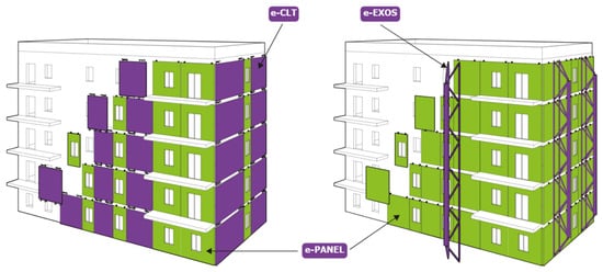
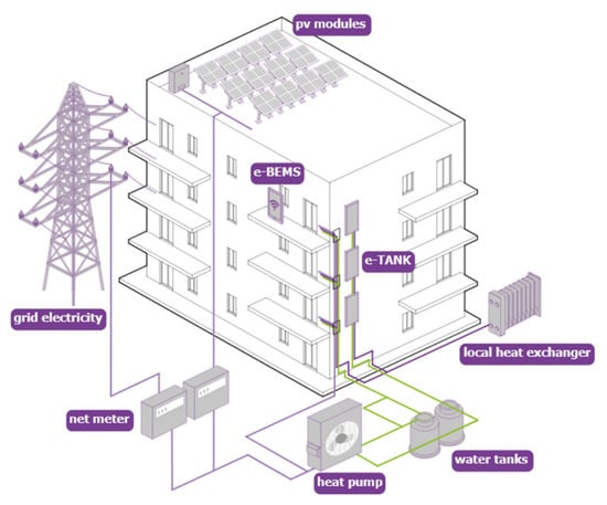
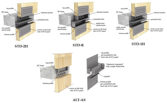
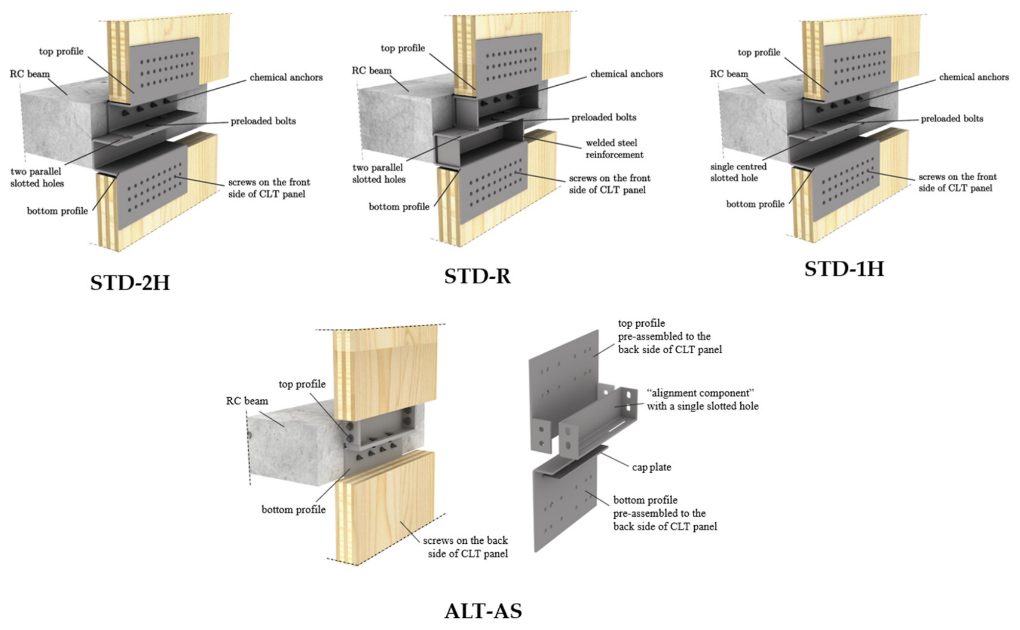
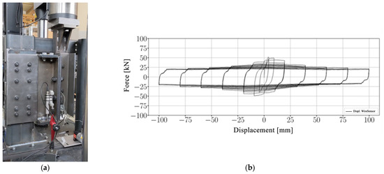
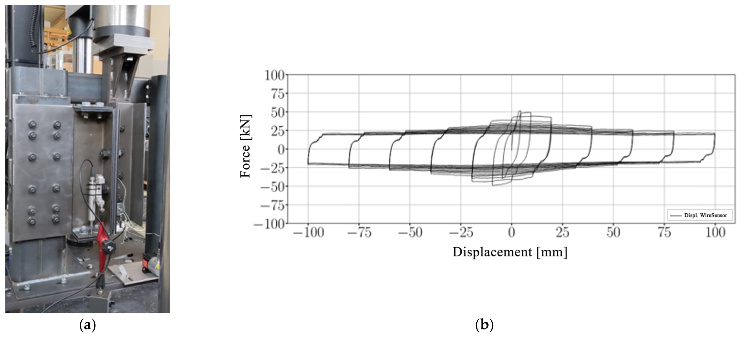
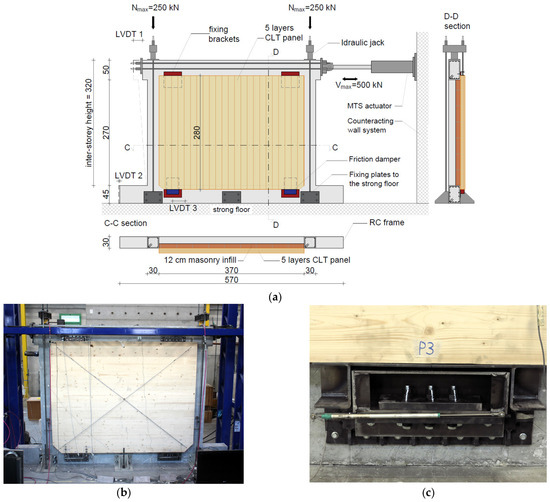
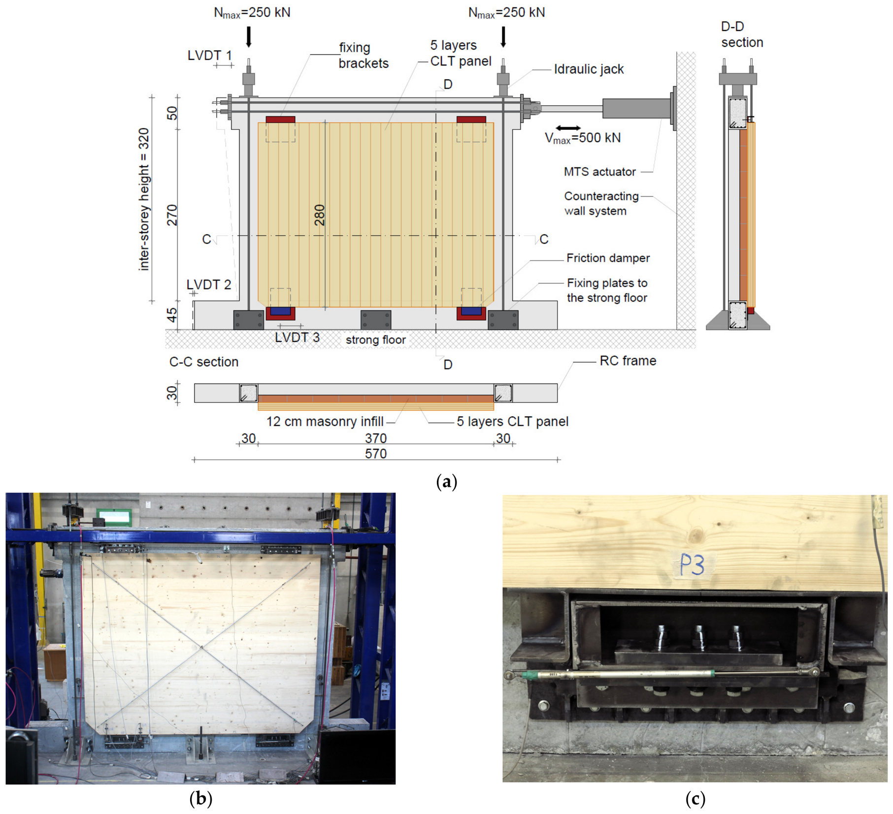
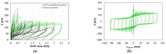
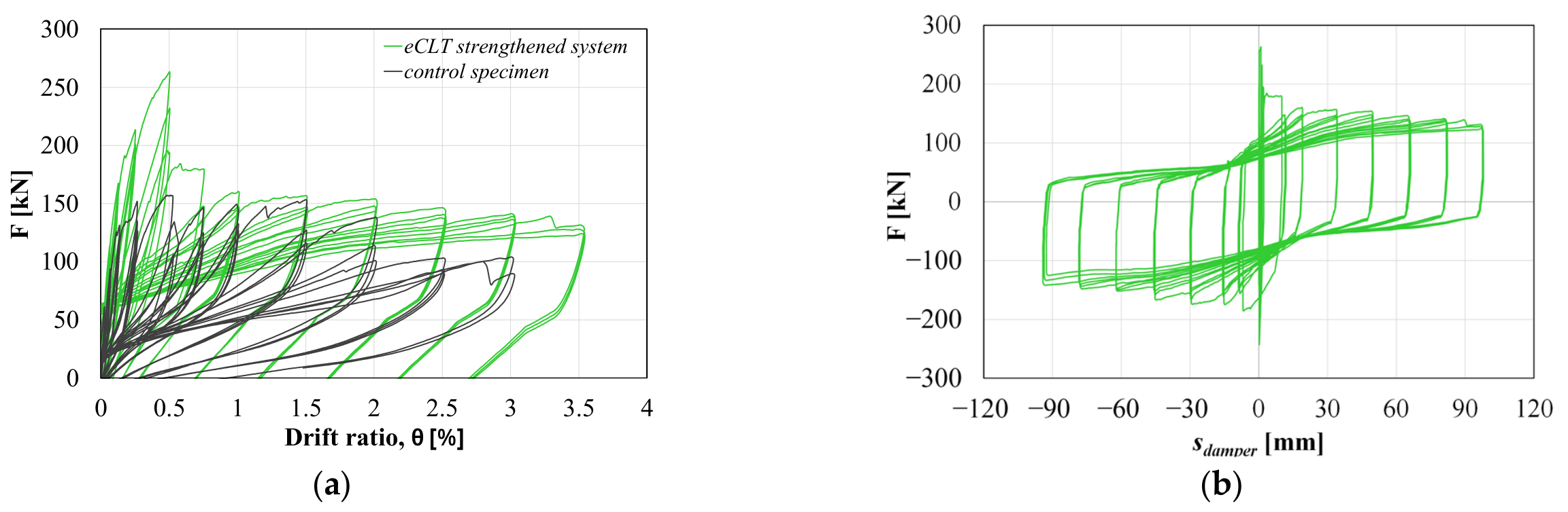
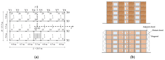
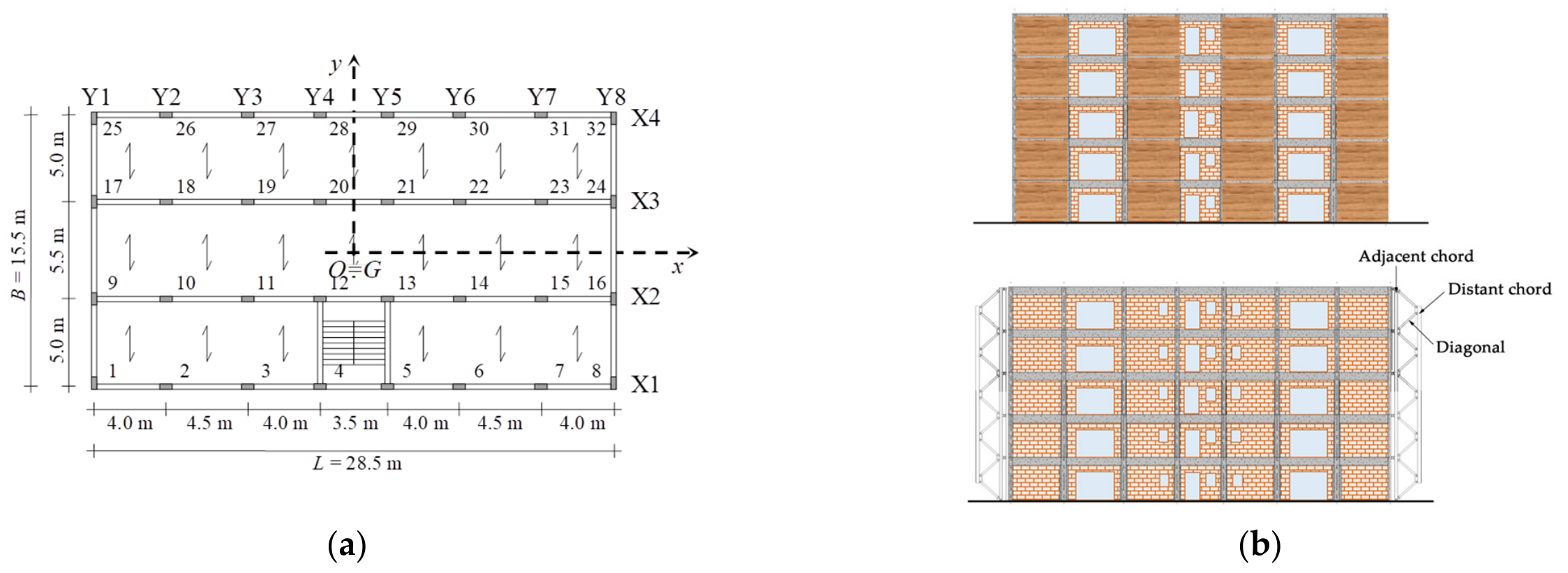
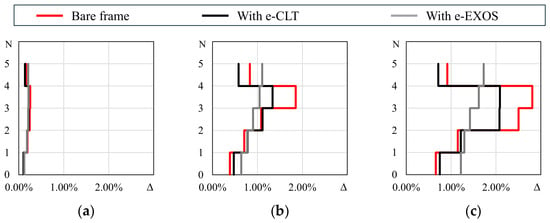
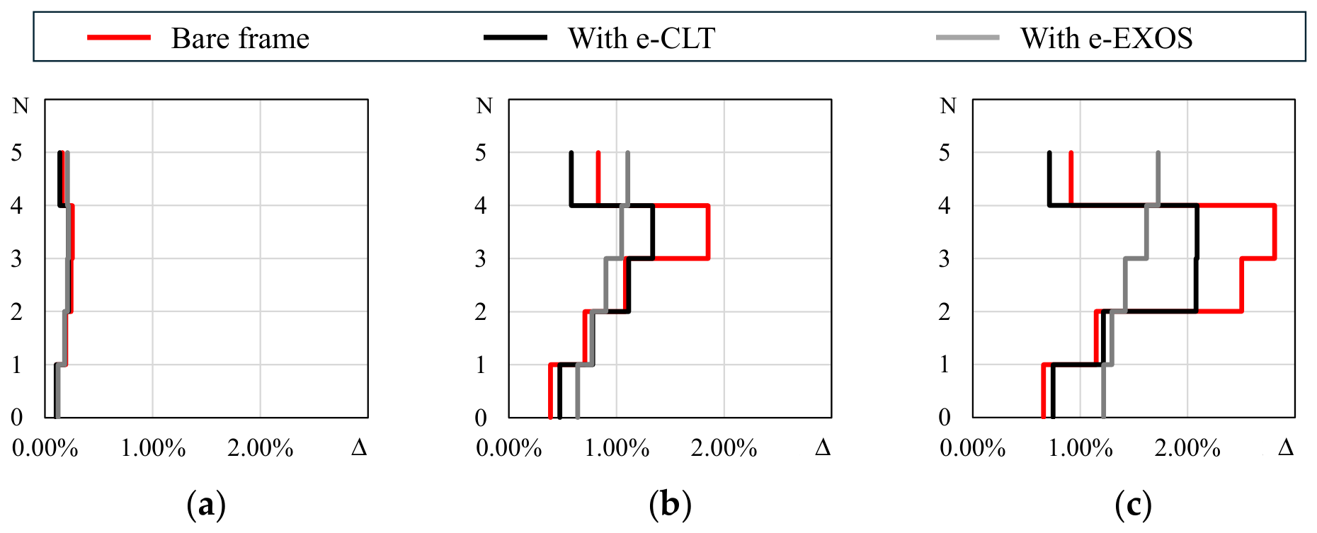
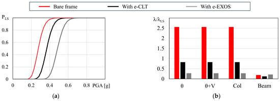
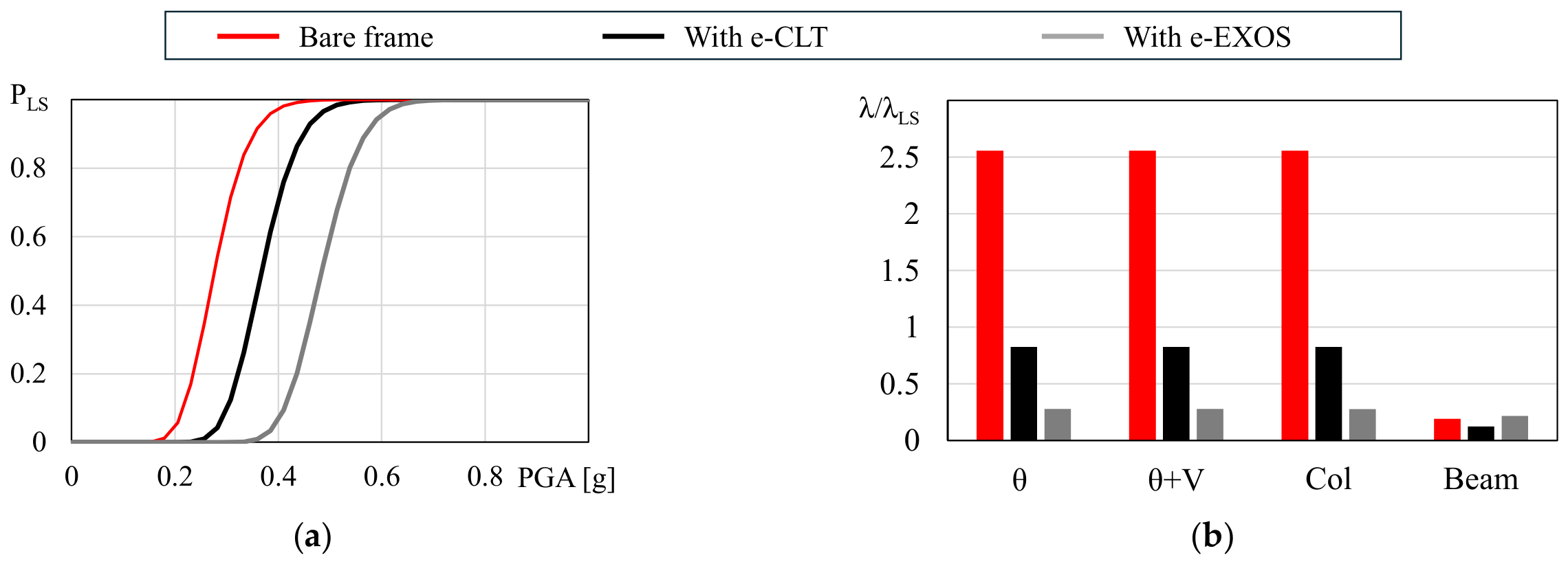
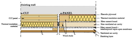
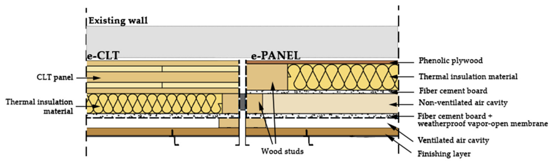
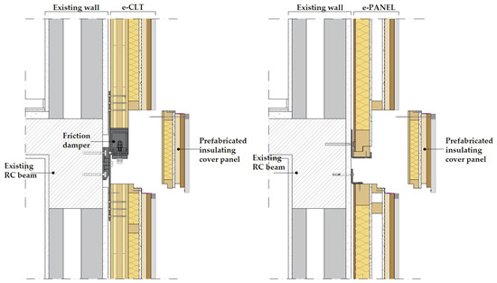
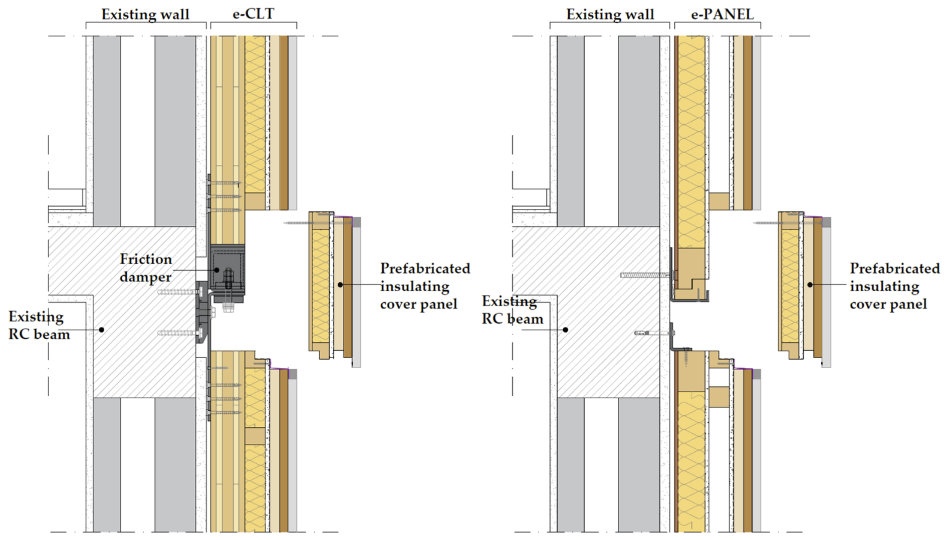
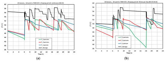
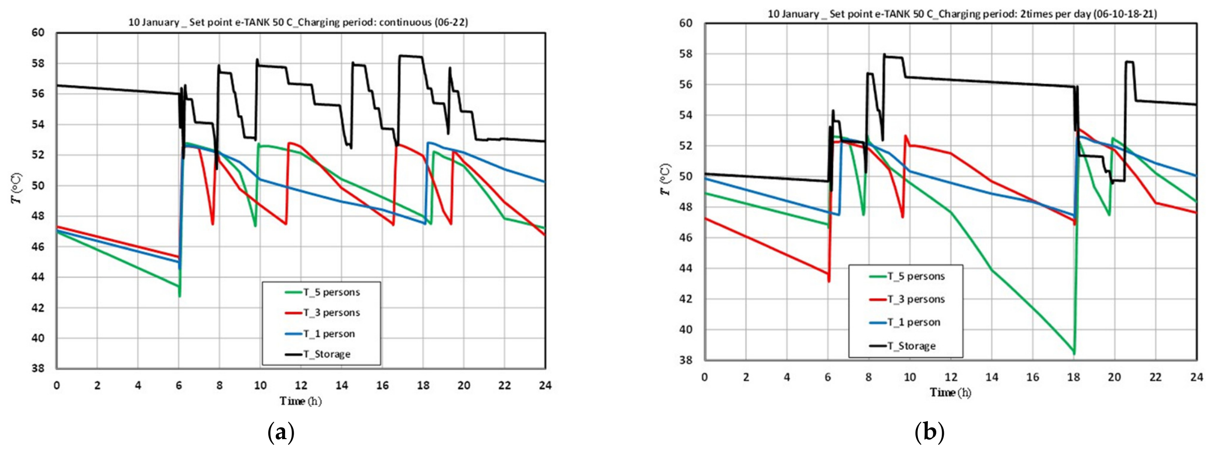
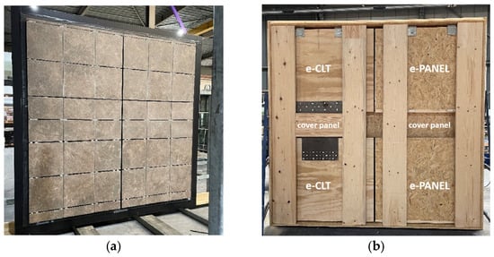
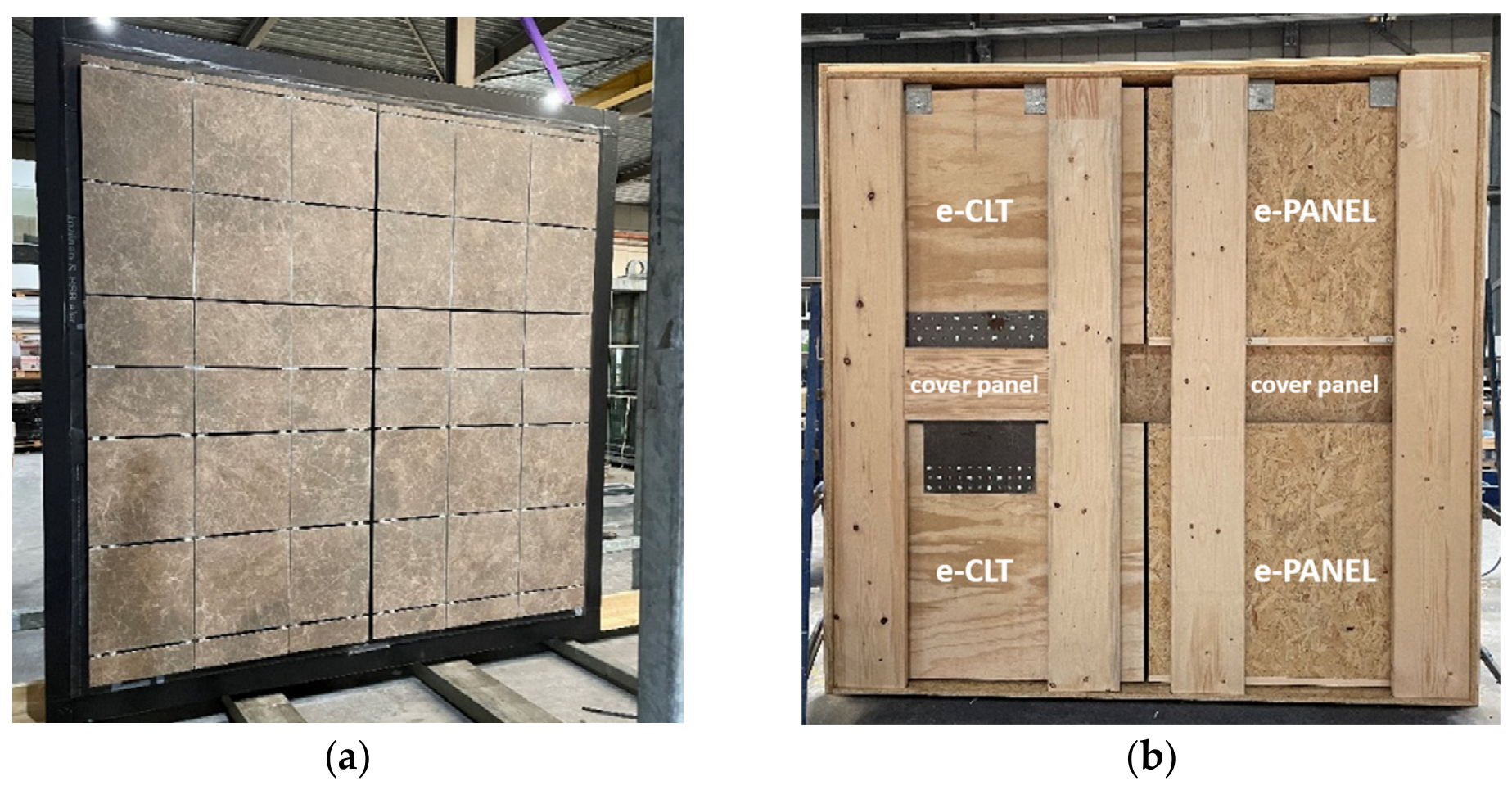
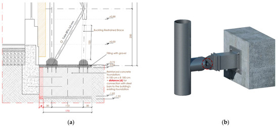
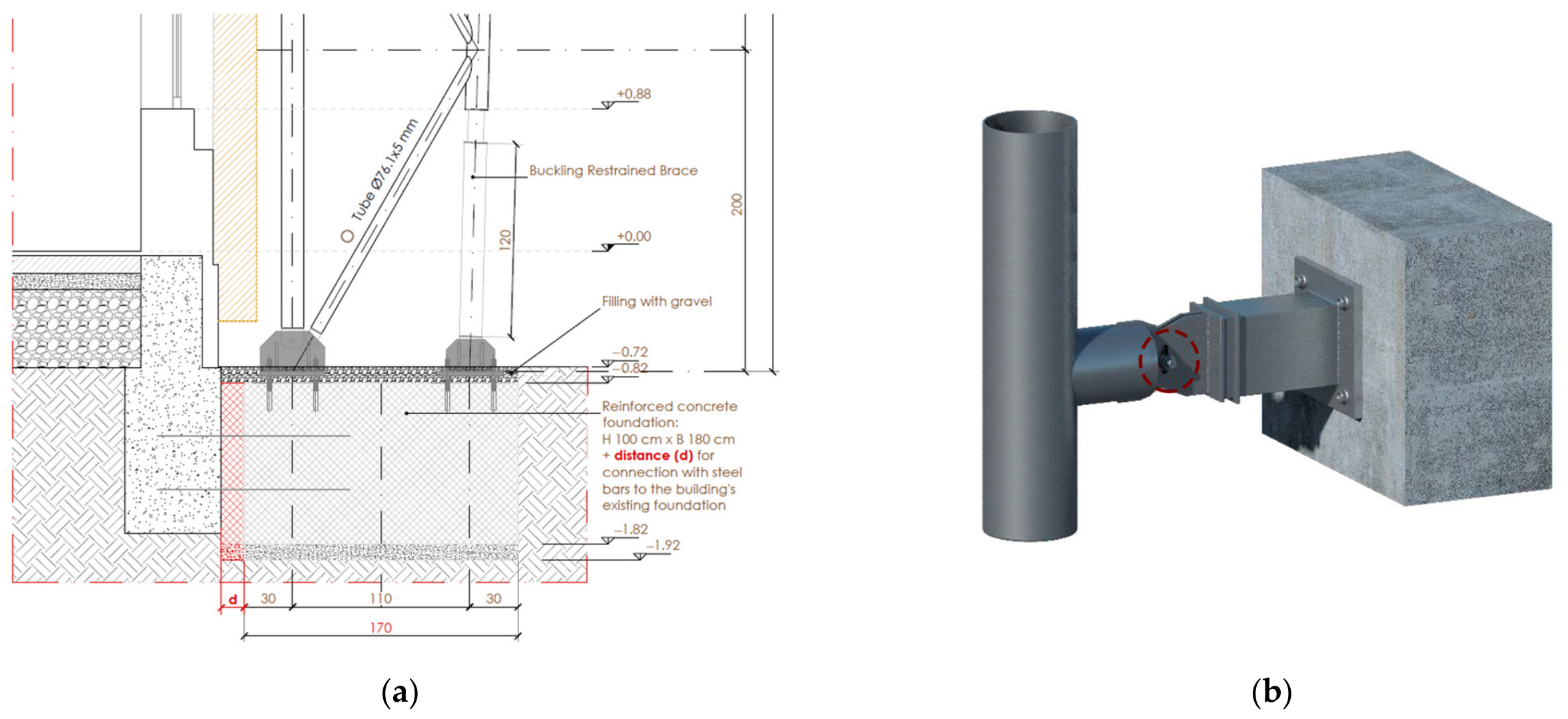
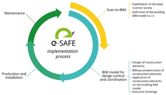
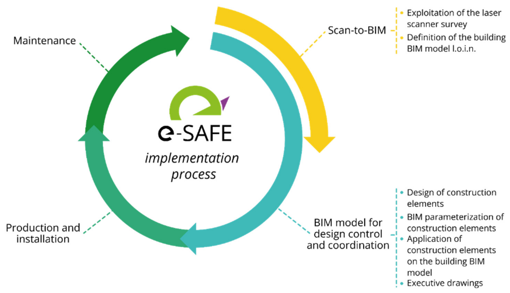
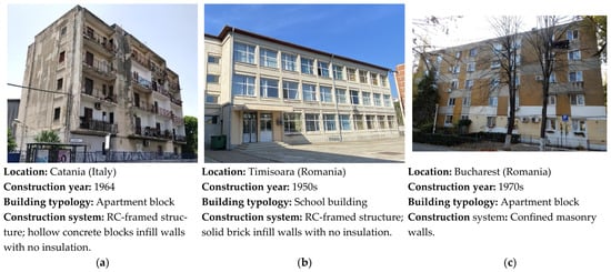
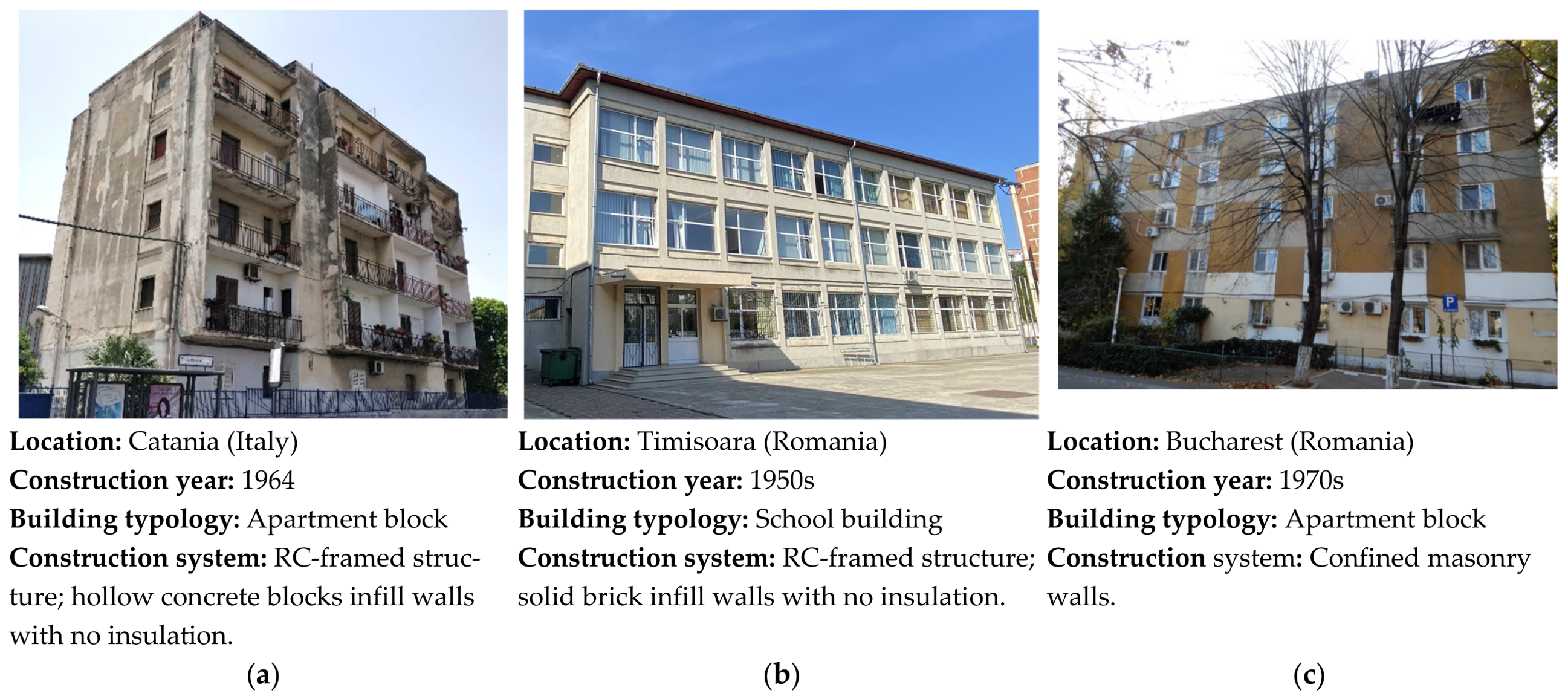
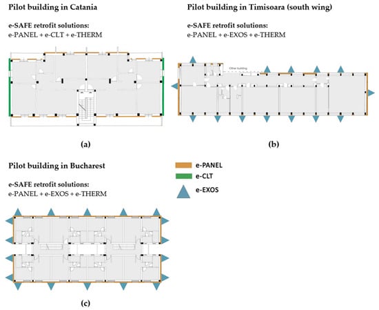
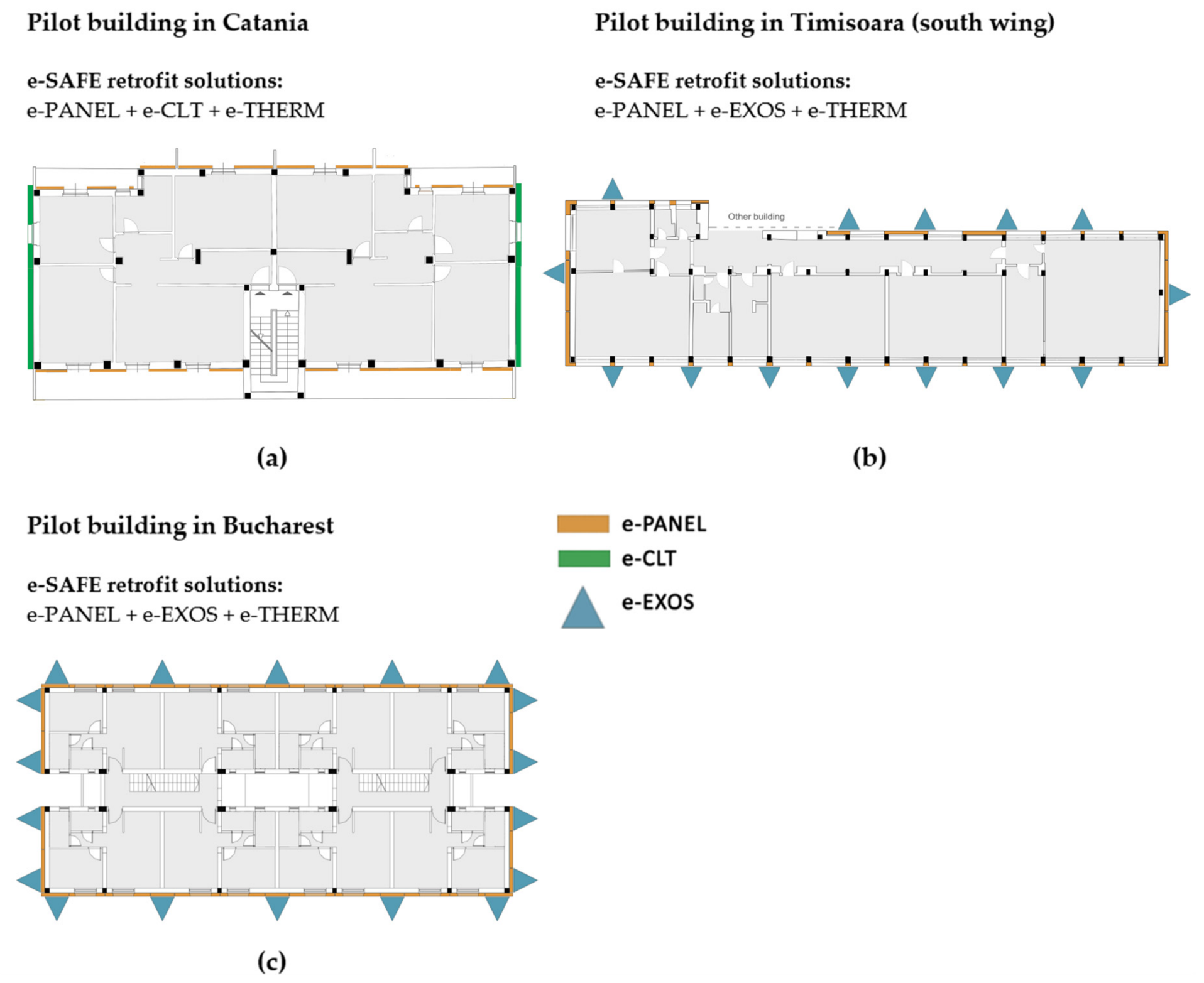
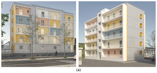
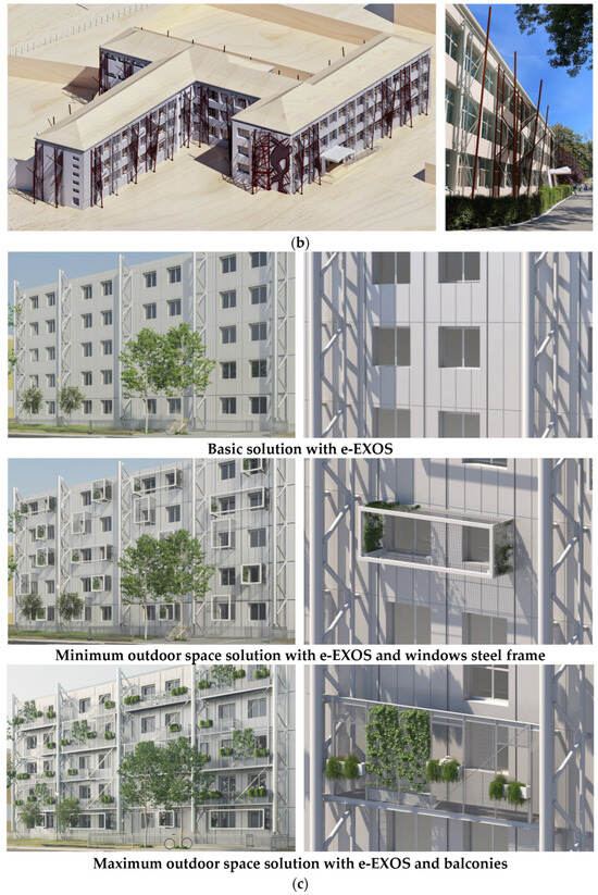
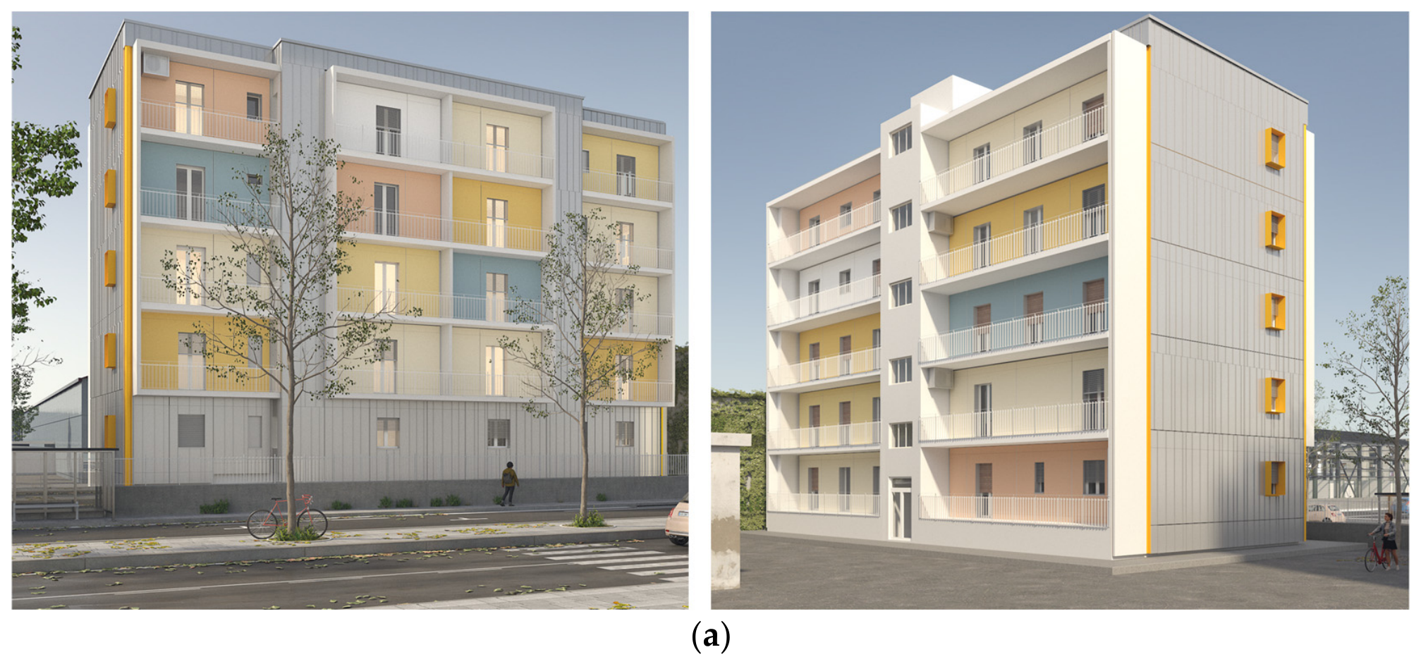
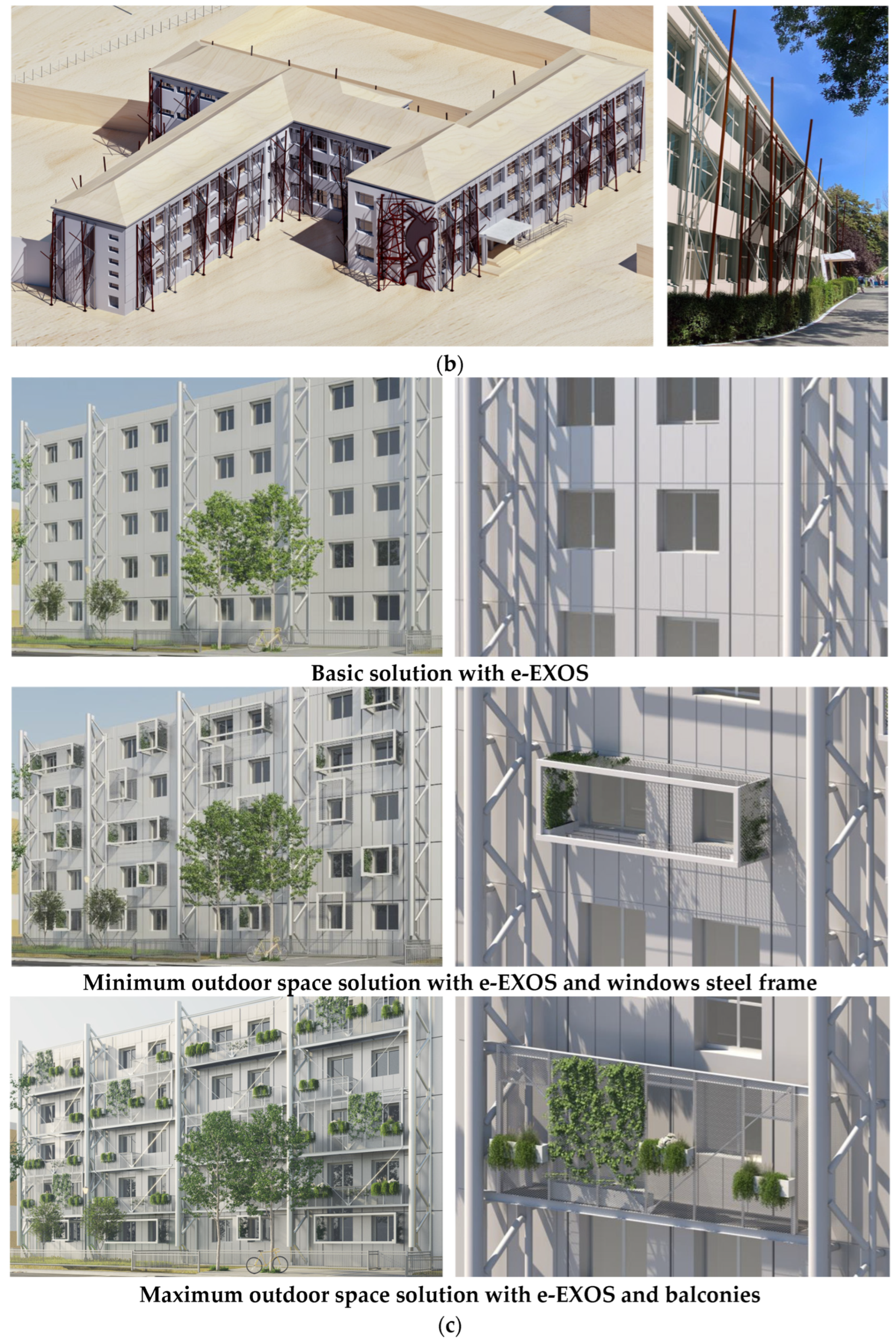
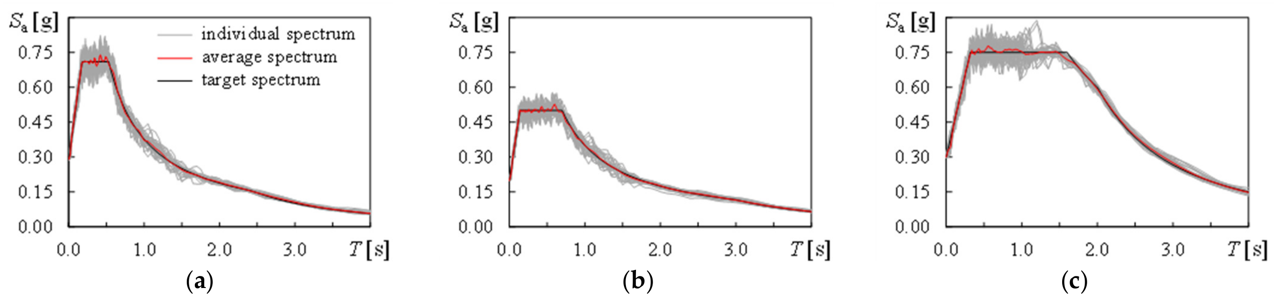
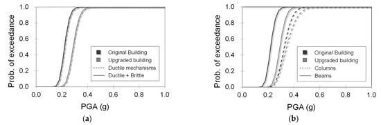
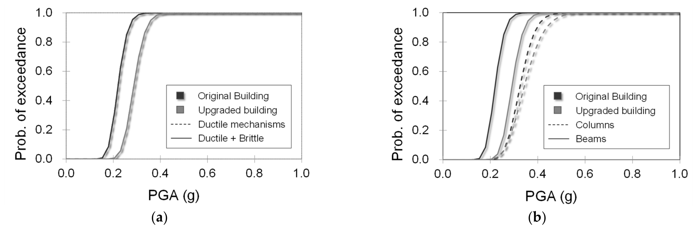
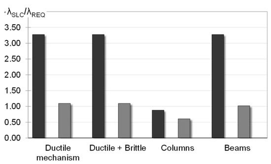
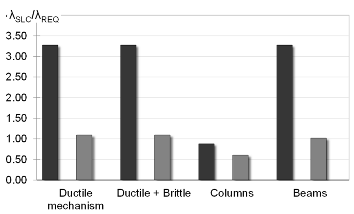
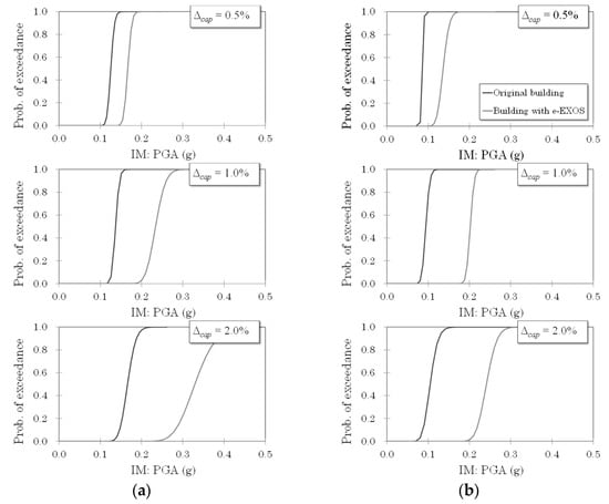
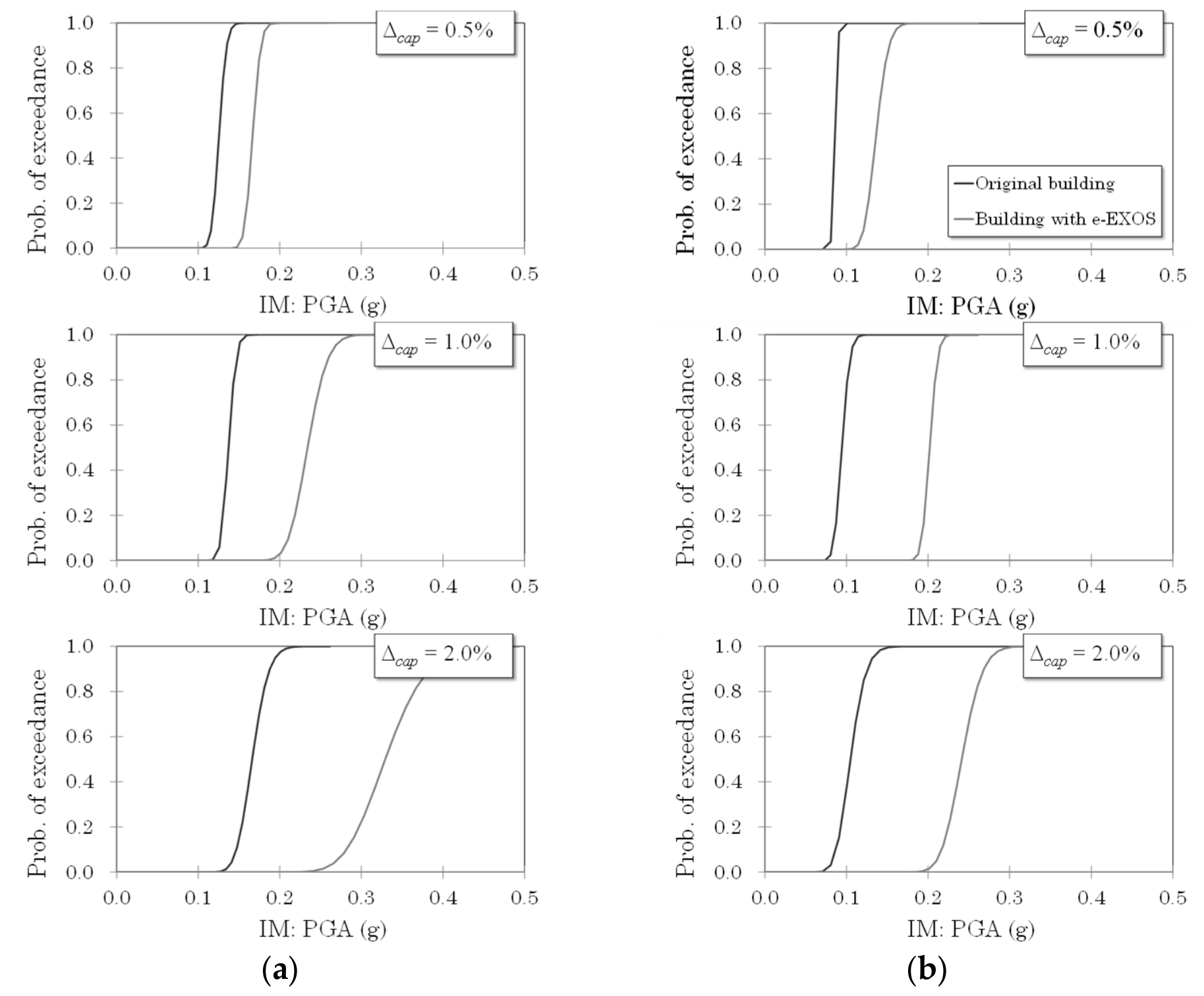
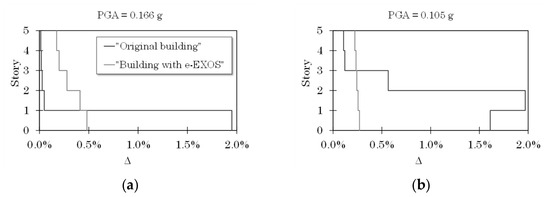
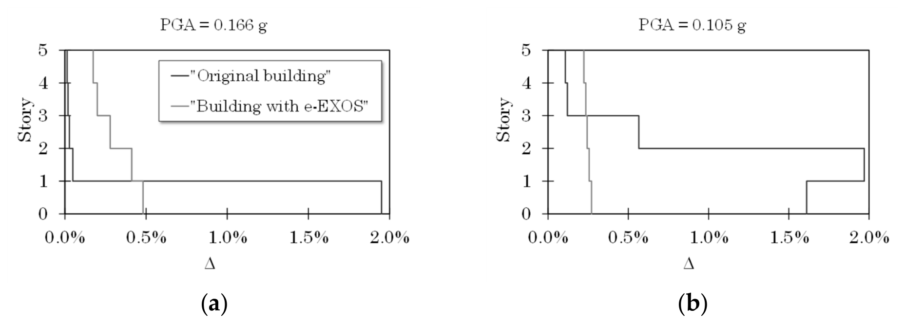
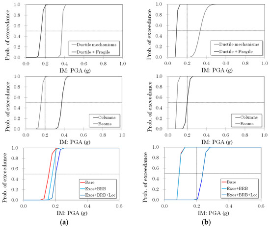
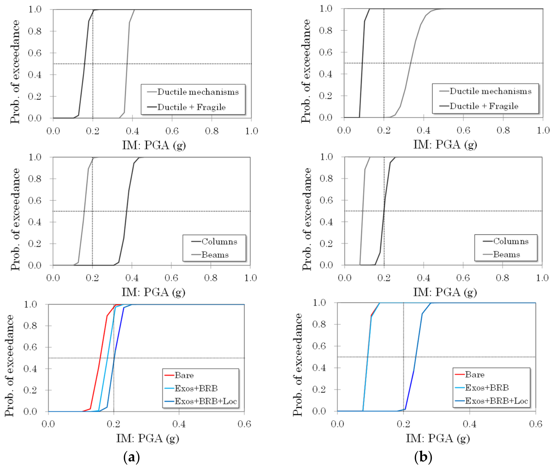
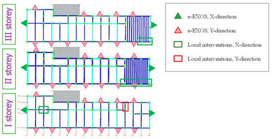
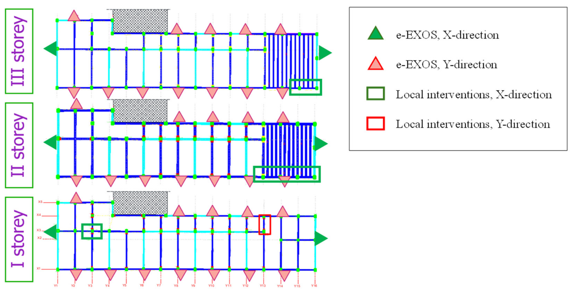
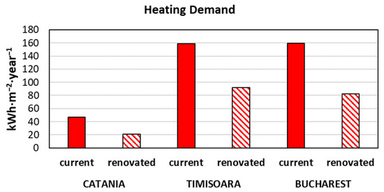
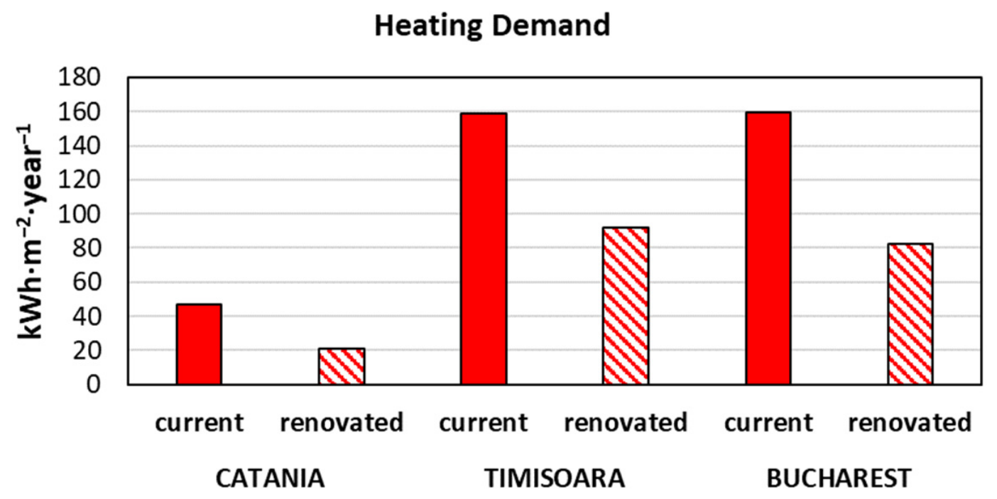
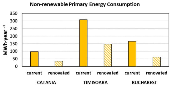
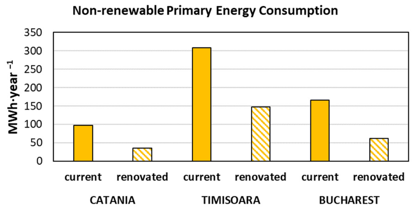
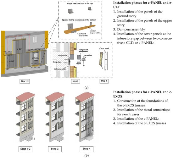
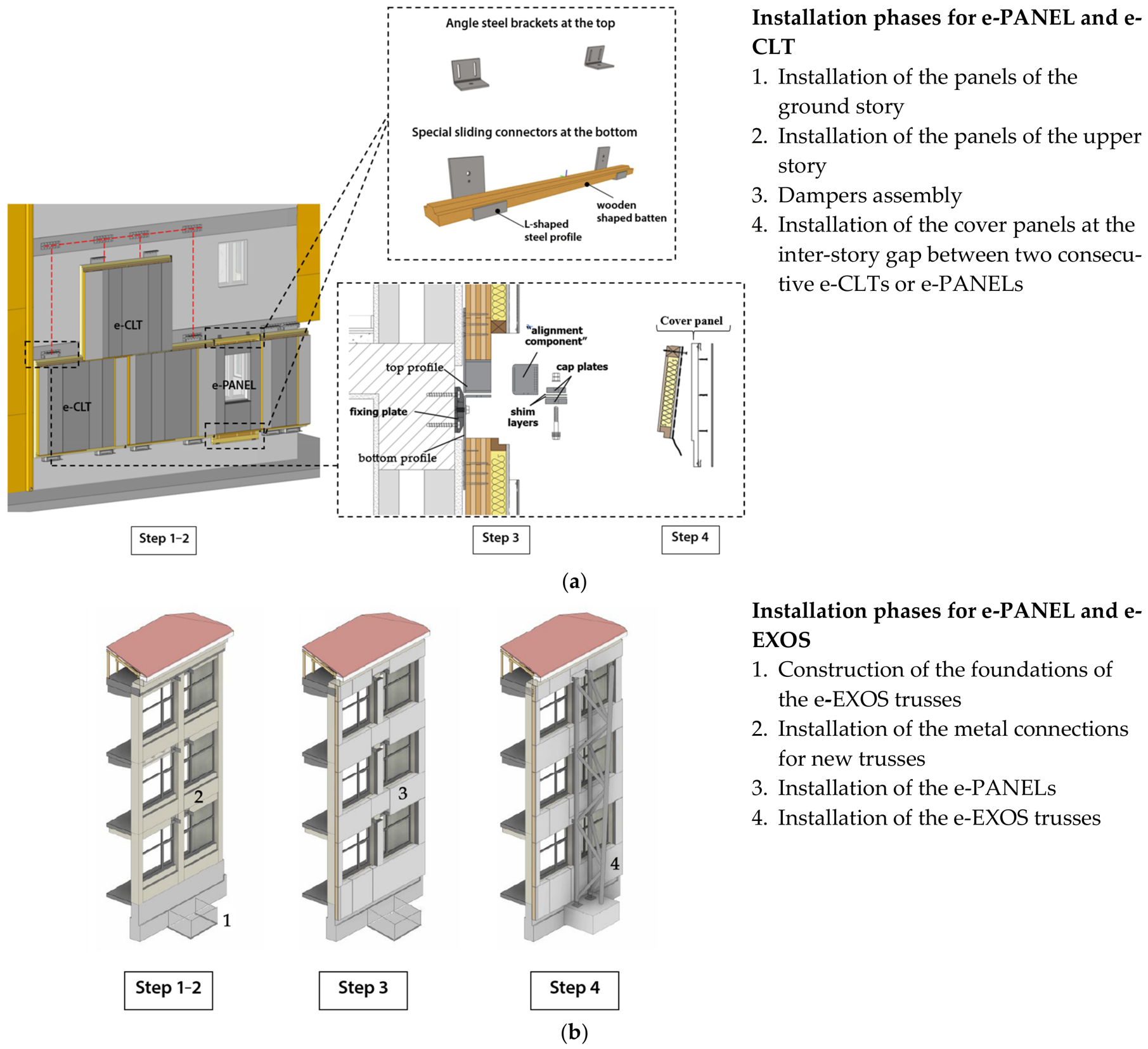
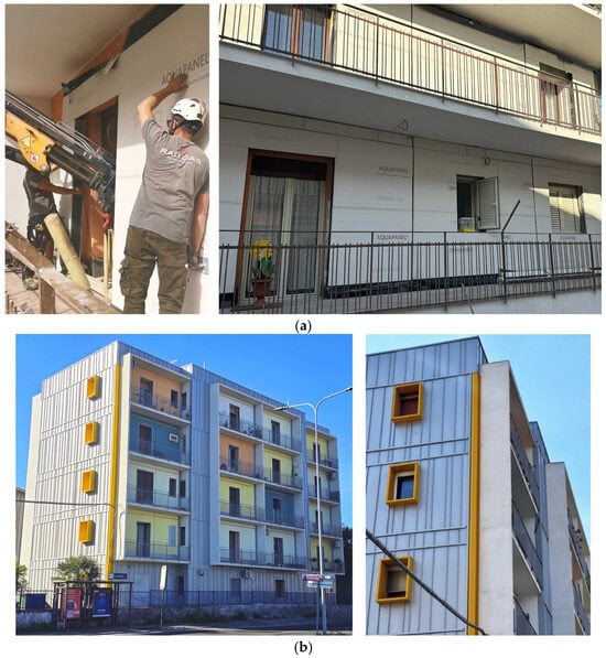
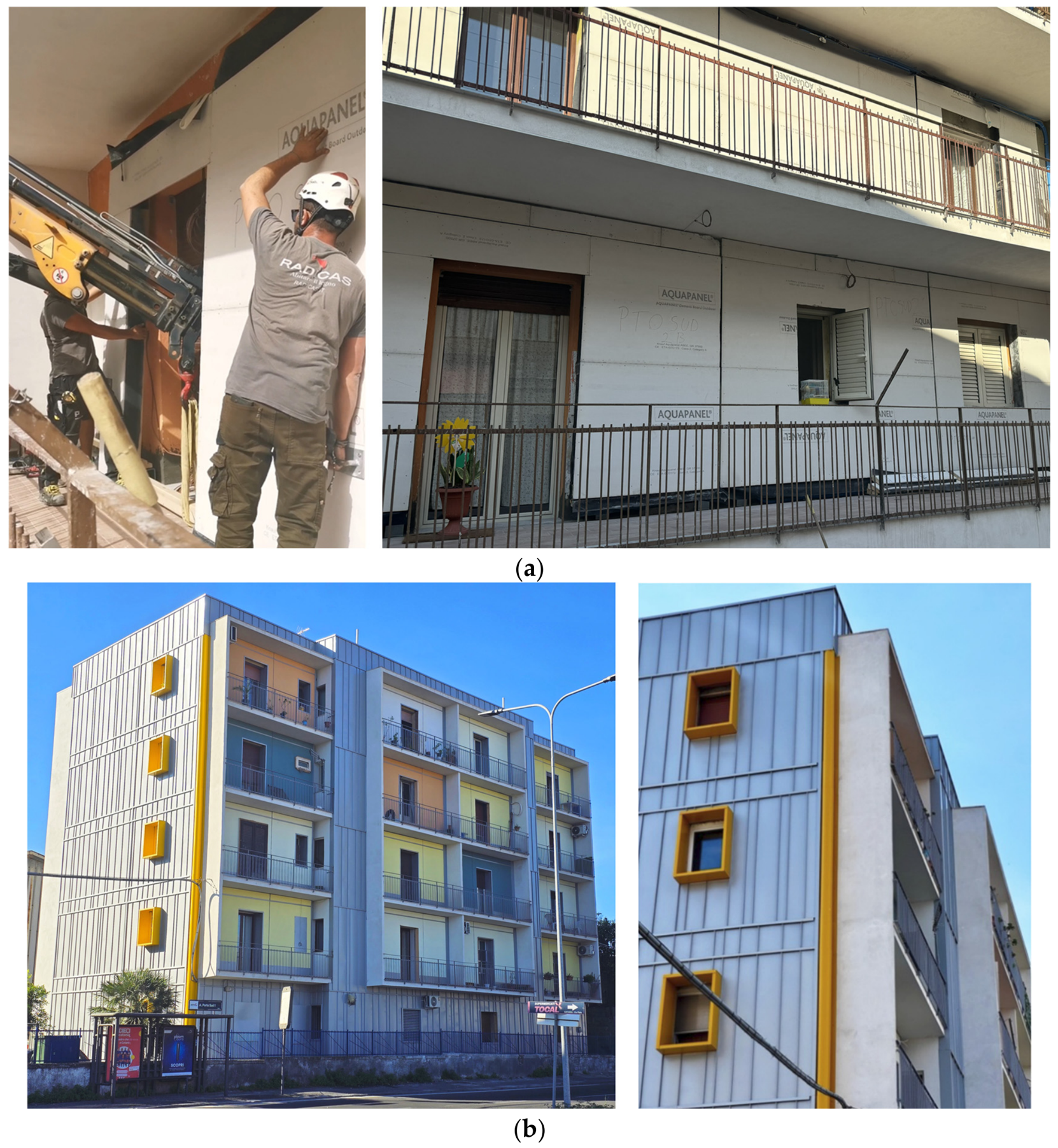

Disclaimer/Publisher’s Note: The statements, opinions and data contained in all publications are solely those of the individual author(s) and contributor(s) and not of MDPI and/or the editor(s). MDPI and/or the editor(s) disclaim responsibility for any injury to people or property resulting from any ideas, methods, instructions or products referred to in the content. |
© 2026 by the authors. Licensee MDPI, Basel, Switzerland. This article is an open access article distributed under the terms and conditions of the Creative Commons Attribution (CC BY) license.