


Abstract
Corrosion-induced cracking is one of the key factors affecting the durability and service life of concrete structures. Accurate measurement of crack initiation, propagation, and spatial distribution provides an important basis for structural durability assessment and maintenance decision-making. This paper systematically reviews the principles, technical characteristics, characterization methods, and development trends of techniques for measuring surface and internal corrosion-induced cracks in concrete, including geometric measurement, strain measurement, optical imaging, elastic-wave techniques, fiber-optic sensing, physical sectioning, X-ray computed tomography (X-CT), and artificial intelligence-assisted analysis. The results show that geometric and optical methods are suitable for quantifying surface crack geometry but have limited capability for identifying early internal damage. Acoustic emission, ultrasonic techniques, and distributed fiber-optic sensing can detect the initiation and evolution of internal cracks, although direct determination of absolute crack dimensions and three-dimensional morphology remains limited. X-CT can reconstruct internal crack networks, but field application is constrained by cost, specimen size, scanning time, and spatial resolution. Multi-source data fusion and artificial intelligence-assisted analysis offer opportunities to improve the comprehensiveness and automation of crack characterization, while improvements in measurement accuracy and reliability require further validation. Future research should focus on low-cost, wireless, long-term online multimodal measurement systems and stable, verifiable quantitative relationships between sensing signals and crack geometric parameters.
1. Introduction
The deterioration of reinforced concrete structures is an important scientific and engineering issue [1,2,3,4,5]. Steel bar corrosion has long been recognized as a major global challenge to the service life of reinforced concrete structures [6,7,8,9,10]. Corrosion of steel bars induced by chloride ions or carbonation is widely regarded as one of the primary factors responsible for shortening the service life of structures [11]. Steel bar corrosion is essentially an electrochemical oxidation process. When steel bars embedded in concrete are exposed to chloride ingress or carbonation, the passive film on the steel bar surface is destroyed, and iron undergoes anodic dissolution (Fe → Fe2+ + 2e−); the resulting Fe2+ reacts with OH− generated at the cathode to form products such as Fe(OH)2, which are eventually transformed into corrosion products such as Fe2O3·nH2O. The volume of these corrosion products can reach approximately 4–6 times that of the original steel, as shown in Figure 1. Initially, the corrosion products fill the small voids at the steel bar–concrete interface. As corrosion progresses, the expanding corrosion products generate tensile stresses within the concrete, eventually causing cracking and even spalling of the concrete cover [12,13,14,15,16,17,18,19].
Figure 1.
Mechanism of steel bar corrosion in concrete.
Corrosion-induced cracking differs from mechanically induced cracking primarily in the source of tensile stress. Corrosion-induced cracks develop as corrosion products expand around embedded reinforcement and often propagate along the reinforcing bars, whereas mechanically induced cracks generally reflect the distribution of stresses caused by external loading. In practical engineering, corrosion-induced cracking can be assessed by considering crack orientation, reinforcement location, rust staining, and concrete cover delamination, together with electrochemical measurements or direct observations of reinforcement corrosion where available; crack appearance alone is insufficient to establish its origin.
Corrosion-induced cracks not only disrupt the integrity of the concrete matrix and reduce the overall stiffness and load-bearing capacity of structures, but also provide pathways for the ingress of aggressive agents, thereby accelerating the penetration of harmful substances such as chloride ions. This process can lead to a detrimental cycle of corrosion, cracking, and further corrosion, substantially shortening the service life of structures and seriously threatening the safety of buildings, bridges, municipal infrastructure, and other engineering structures [20,21,22]. Therefore, accurate measurement of crack initiation, propagation, and spatial distribution, together with precise characterization of the evolution of corrosion-induced cracking, is essential for assessing structural damage, predicting service performance, and formulating maintenance and strengthening strategies.
According to their spatial location, corrosion-induced cracks can be classified into surface cracks and internal cracks. Current measurement techniques for corrosion-induced cracks mainly include manual geometric measurement, optical techniques, elastic-wave-based techniques, physical sectioning, three-dimensional (3D) visualization, and artificial intelligence (AI)-based techniques. Geometric measurement methods, such as vernier calipers, feeler gauges, crack width gauges, and optical microscopes, are simple to operate and can directly measure the width and variation of surface cracks. However, they rely largely on manual operation and are unable to adequately capture the overall crack distribution or internal crack development [23]. Optical techniques, such as digital image correlation (DIC), can provide full-field displacement and strain information on concrete surfaces, thereby enabling identification of crack initiation locations and crack propagation processes. Nevertheless, their measurement range is limited to visible surfaces, and the results are readily affected by illumination conditions, camera stability, and surface texture [24]. For internal cracks that have not yet propagated to the concrete surface, acoustic emission (AE), ultrasonic techniques, and fiber-optic sensing can detect crack initiation and development through changes in stress waves, propagating waveforms, or strain responses [25,26,27]. These techniques have the potential for continuous or real-time measurement, but the acquired data are generally acoustic, wave-based, or strain signals. Further relationships therefore need to be established between the measured signals and crack location, crack type, and geometric parameters. Physical sectioning is a destructive method that enables direct observation of corrosion products and crack morphology at the steel bar–concrete interface [28].
With the continuous development of measurement technologies, new intelligent approaches have emerged. X-ray computed tomography (X-CT) enables nondestructive reconstruction of internal corrosion products and crack networks, providing an important tool for investigating the three-dimensional evolution of corrosion-induced cracking [29]. However, its application remains constrained by equipment cost, specimen size, and scanning time. In recent years, AI-assisted analysis has increasingly been applied to feature extraction and crack identification from images, acoustic emission signals, and other measurement data, providing new opportunities to improve data-processing efficiency and measurement automation [30].
Although crack measurement is not a new research topic, real-time measurement and quantitative characterization of the spatiotemporal evolution of corrosion-induced cracks in reinforced concrete remain major challenges. A number of reviews have addressed the measurement of corrosion-induced cracking in reinforced concrete [31,32,33,34,35,36,37,38]. Mousa et al. [31] systematically summarized the application of DIC to the measurement of surface displacement fields, strain fields, crack initiation, and crack propagation. Verstrynge et al. [33] reviewed signal analysis, damage localization, and field applications of AE for measuring concrete cracking induced by steel bar corrosion. Taheri-Shakib and Al-Mayah [34] summarized the application of X-CT to the characterization of corrosion-product distribution and the three-dimensional evolution of corrosion-induced cracks. Zhang et al. [35] reviewed advances in distributed fiber-optic sensing for crack initiation detection, crack localization, and crack-width measurement in concrete. Zhuang et al. [37] reviewed recent advances in deep learning for surface crack detection in civil engineering, with particular emphasis on datasets, evaluation metrics, and algorithmic tasks. Golewski et al. [38] systematically reviewed cracking in cement-based concrete and reinforced concrete structures in terms of crack formation mechanisms, inducing factors, crack types, and detection methods. The research scope, measurement techniques, and characterization characteristics of previous reviews are compared in Table 1.
Table 1.
Comparison of previous reviews related to concrete cracking, reinforcement corrosion monitoring, and measurement techniques.
Although previous reviews have discussed combined measurement techniques and integrated monitoring [31,32,33,35,36,37,38,39], consistent comparisons focused on corrosion-induced crack geometry, surface and internal characterization, quantitative validation, and the complementary roles of different measurement techniques remain limited. Therefore, this review focuses on measurement techniques for corrosion-induced cracks in reinforced concrete and systematically examines their principles, technical characteristics, characterization parameters, and current state of development. Particular attention is given to recent advances in three-dimensional visualization and AI-assisted techniques for measuring corrosion-induced cracking. The review aims to provide a reference for the future development of more intelligent and refined measurement approaches for corrosion-induced cracks in reinforced concrete.
2. Review Methodology
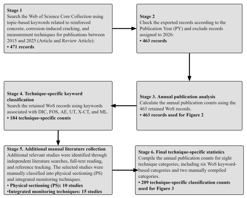
A bibliometric analysis was conducted using the Web of Science Core Collection to identify publications related to the measurement and characterization of corrosion-induced cracks in reinforced concrete from 2015 to 2025. The initial search retrieved 471 records. After excluding eight records with a publication year of 2026, 463 records were retained for the annual publication analysis presented in Figure 2. Publications associated with different measurement techniques were further compiled using technique-specific keyword searches and manual literature collection. The technique-specific categories were not mutually exclusive, and a publication could be counted in multiple categories if it matched the corresponding search criteria. In particular, studies involving physical sectioning (PS) and integrated monitoring techniques were identified through independent literature searches, full-text reading, and reference tracking. For integrated measurement techniques, studies were included only when at least two different measurement techniques were applied to measure or characterize corrosion-induced cracks. The detailed search strategies and annual counts are provided in Supplementary Tables S1 and S2. The 2015–2025 publication-year restriction applies only to the bibliometric analysis, whereas the broader narrative review includes relevant earlier studies and recent publications up to 14 October 2026, including studies published in 2026. These studies were not included in the 2015–2025 bibliometric counts.
Figure 2 presents the annual number of publications retrieved from the Web of Science Core Collection between 2015 and 2025. An overall upward trend can be observed, with the number of retrieved records increasing from 16 in 2015 to 76 in 2025, representing an approximately 4.8-fold increase. Figure 3 presents the annual distribution of the literature compiled for different measurement and characterization techniques for corrosion-induced cracks.The literature retrieval and classification procedures are illustrated in Figure 4. The literature was selected and classified by technique, and the annual counts therefore reflect the publications included in the corresponding technique categories rather than all publications in the field. The distributions vary across techniques, with a particularly noticeable increase in publications associated with machine learning (ML) in recent years. These publication trends reflect changes in research activity rather than the measurement performance, practical applicability, or technological maturity of individual techniques.
Figure 2.
Annual number of publications from 2015 to 2025.
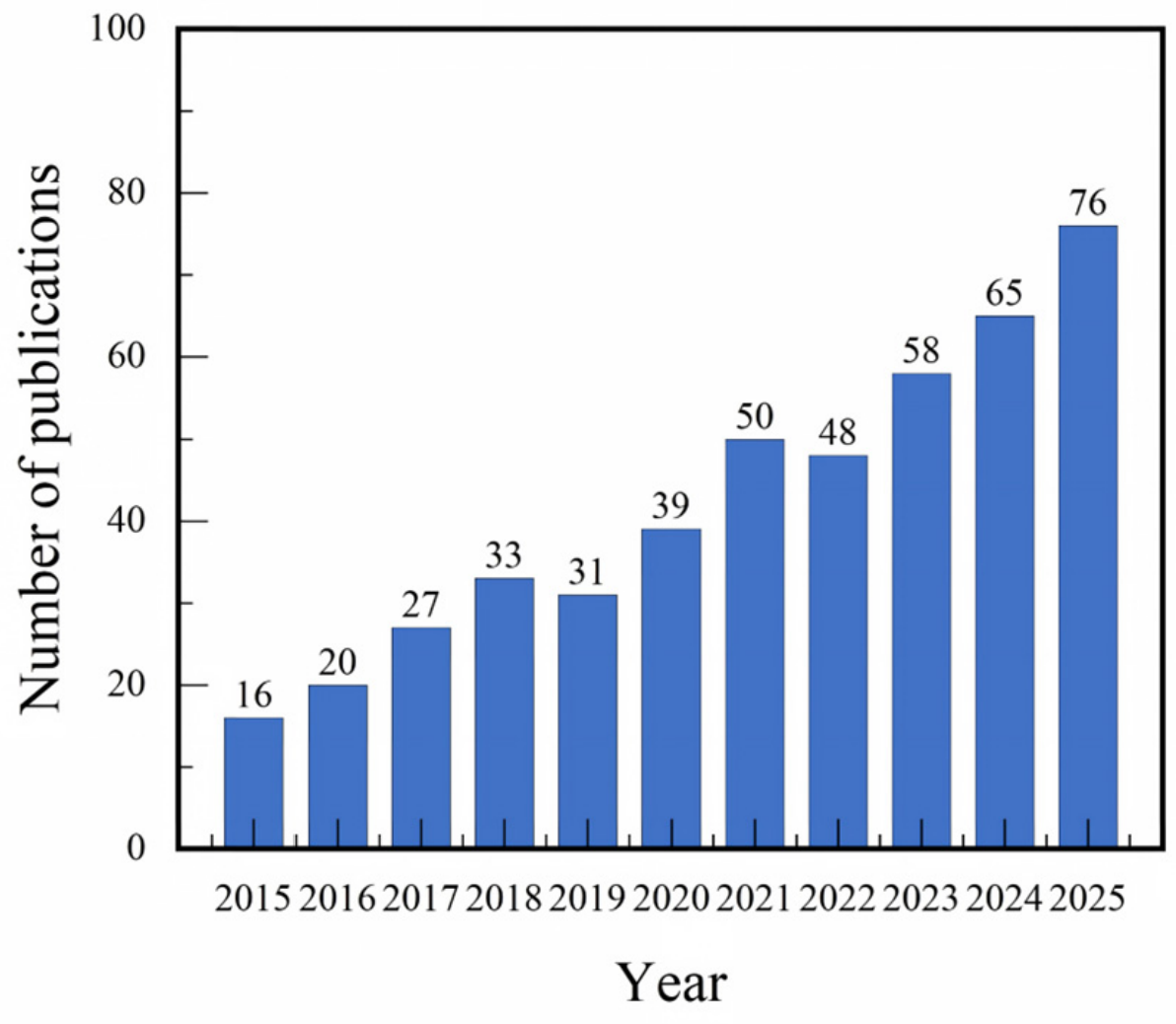
Figure 3.
Distribution of measurement techniques for corrosion-induced cracks.
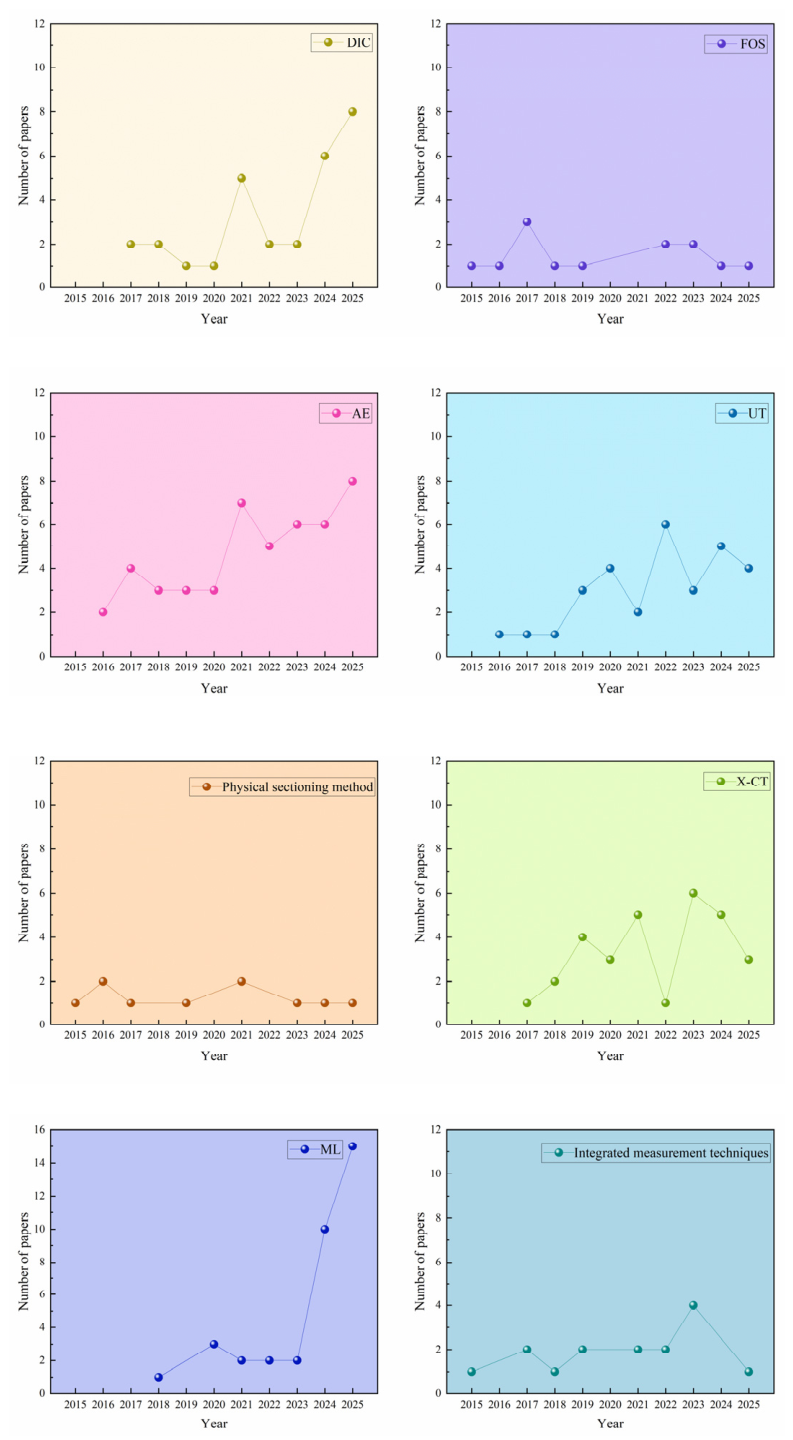
Figure 4.
Flowchart of the literature retrieval and technique-specific classification procedures.
3. Surface Crack Measurement Techniques
In this review, crack initiation detection refers to identifying the onset of cracking based on direct observations or changes in measured signals, with detection thresholds specified where reported. Crack localization and propagation tracking refer to determining the crack position and its development over time. Changes in acoustic, ultrasonic, or strain signals are regarded as indirect indicators of cracking unless their relationships with crack parameters have been quantitatively established. Direct geometric measurements are distinguished from crack dimensions obtained through image analysis or three-dimensional reconstruction. The reliability of quantitative results depends on measurement uncertainty, calibration, and validation against independent reference measurements, where available. The distinction between surface and internal crack measurement techniques in Section 3 and Section 4 is based on the principal crack information addressed in the reviewed studies rather than an exclusive classification of measurement capabilities. Depending on sensor arrangement and observation configuration, surface-mounted AE or ultrasonic sensors can provide indirect information on internal cracking, whereas DIC can characterize cracks on exposed end faces or cross sections but cannot directly observe cracks hidden within the concrete.
3.1. Geometric Measurement Techniques
Geometric measurement techniques are a relatively mature category of methods for measuring surface cracks in concrete. These techniques mainly employ length-measuring instruments, thickness gauges, or optical imaging devices to directly measure the width and variation of cracks that have already appeared on the concrete surface [23]. Owing to their simple equipment, convenient operation, and intuitive measurement results, geometric measurement techniques are widely used in engineering inspections, laboratory tests, and the validation of results obtained using other measurement techniques. Commonly used methods include vernier calipers, feeler gauges, crack magnifiers or microscopes, and digital crack width gauges.
3.1.1. Vernier Caliper
A vernier caliper measures crack opening width directly by bringing its jaws into contact with the two edges of a crack, and is therefore suitable for surface cracks with relatively large openings and clearly defined edges. During measurement, the caliper should be oriented as nearly perpendicular as possible to the crack path, and fixed measurement points should be established along the crack to ensure consistency in measurement locations at different stages. For corrosion-induced cracks whose width varies markedly along the crack length, measurements are generally taken at multiple locations, including the crack origin, middle section, maximum opening, and crack end. Vernier calipers have the advantages of low cost, portability, and straightforward readings. However, the jaws are difficult to fit accurately to narrow cracks or cracks with irregular edges, making this method more suitable for measuring relatively wide cracks or the dimensions of local spalling, as shown in Figure 5.
Figure 5.
Measurement of crack width using a vernier caliper.
3.1.2. Feeler Gauge
A feeler gauge consists of a set of thin metal blades with different nominal thicknesses. During measurement, blades of different thicknesses are inserted sequentially into the crack, and the thickness of the largest blade that can be inserted without noticeable looseness is taken as an approximate value of the local crack width. Compared with a vernier caliper, a feeler gauge is more suitable for narrow cracks with sufficient opening depth. However, the measurement result can be affected by crack-edge roughness, internal crack geometry, insertion depth, insertion angle, and operator judgment. When the internal crack width varies with depth, the feeler-gauge reading only represents the local dimension near the insertion position and cannot characterize the complete internal geometry of the crack, as shown in Figure 6.
Figure 6.
Measurement of crack width using a feeler gauge. The Chinese markings visible on the instrument are part of the original photographed device.
3.1.3. Crack Microscope
This type of instrument uses an optical magnification system and a graduated scale to observe and measure a local crack region. During measurement, the instrument is positioned perpendicular to the concrete surface, and the focus is adjusted until the crack edges are clearly resolved. The crack width is then determined from the eyepiece scale or a calibrated scale factor. The nominal resolution of an instrument should be distinguished from its actual measurement accuracy, which may be affected by calibration and crack-edge identification, particularly for irregular concrete cracks. Because no measuring component needs to be inserted into the crack, contact interference with the crack edges can be reduced, making this type of instrument suitable for relatively narrow surface cracks with clearly defined edges. Its main limitations are the small field of view and the dependence of the measurement results on manual focusing, scale alignment, and crack-edge identification, which make rapid large-area inspection difficult, as shown in Figure 7.
Figure 7.
Crack microscope for crack width measurement.
3.1.4. Digital Crack Width Gauge
A digital crack width gauge essentially combines a high-magnification miniature digital microscope with image-processing algorithms. The front-end probe is equipped with an integrated light source, typically an LED to minimize interference from ambient illumination, and a high-resolution miniature CMOS or CCD camera. When the probe is placed against the concrete surface, the local crack region can be magnified by several tens to more than one hundred times. The magnified image is transmitted in real time to the display of the main unit. An embedded microprocessor then applies image-processing algorithms, such as grayscale threshold segmentation, to automatically identify the boundary between the dark crack region and the lighter concrete surface. Based on the factory-calibrated relationship between image pixels and actual physical dimensions, the instrument can rapidly calculate the actual crack width and display the measurement result directly on the screen, as shown in Figure 8. The measurement principles, characterization parameters, and applicability of commonly used manual surface crack measurement methods are summarized in Table 2.
Figure 8.
Crack width gauge for crack width measurement.
Table 2.
Common manual methods for measuring surface crack width and their applicability.
3.2. Strain Measurement Techniques
Surface strain measurement techniques are contact-based methods that measure local surface deformation and strain variations by attaching strain gauges to the surface of a specimen or by establishing measurement points with a prescribed gauge length. The basic principle is that, when the measured object deforms, the distance between surface measurement points or the strain gauge deforming together with the surface changes accordingly. Surface strain is then obtained by recording the local elongation or contraction and converting it into strain. The expansion of steel bar corrosion products induces deformation of the concrete cover surface. As corrosion-induced cracks initiate and propagate, the tensile strain at the measurement points and its temporal variation also change, as shown in Figure 9. Therefore, surface strain measurement techniques can characterize the initiation and propagation of corrosion-induced cracks based on the magnitude of surface strain, its rate of increase, and the changes observed before and after cracking.
Figure 9.
Schematic diagram of strain-gauge measurement during accelerated steel bar corrosion.
Researchers have employed surface strain measurement techniques to monitor concrete cover deformation and cracking induced by steel bar corrosion. Andrade et al. [40] bonded strain gauges to the surfaces of reinforced concrete specimens and continuously recorded the tensile deformation of the concrete surface during accelerated corrosion while simultaneously monitoring crack-width development. The results showed pronounced differences in surface deformation among different measurement points. Corrosion-induced cracks initially appeared discontinuously at localized positions and subsequently widened non-uniformly along the concrete surface. Muñoz et al. [41] arranged strain gauges on the surfaces of reinforced concrete specimens and identified concrete cover cracking behavior from the temporal evolution of surface strain during accelerated corrosion. They found that the strain gauges captured the increase in surface strain caused by corrosion-product expansion, and that the surface strain reached a peak when the first surface crack appeared. This response could therefore be used to identify the time of surface cracking and the subsequent stage of crack development. Malumbela et al. [42,43] used a 100 mm demountable mechanical strain gauge to measure transverse strains in the corrosion-affected region and along potential cracking surfaces of accelerated-corrosion reinforced concrete beams. They found that the transverse tensile strain on the corrosion-affected surface increased continuously before the appearance of the first visible corrosion-induced crack, indicating that surface transverse strain could reflect the location and propagation of corrosion-induced cracks before they became visually observable. Chen et al. [44] conducted accelerated corrosion tests on reinforced concrete prism specimens, with four strain gauges bonded to the top surface in a direction perpendicular to the steel bars while visible crack widths were measured simultaneously. They observed failure of the strain gauges when the cracks propagated to the top surface of the specimens. Accordingly, changes in the surface strain curves and strain-gauge failure could be used to identify the stages of internal cracking and crack arrival at the concrete surface, respectively. Zhang and Su [45] arranged strain gauges with a gauge length of 10 mm on the surfaces of accelerated-corrosion reinforced concrete cover specimens and investigated the cover cracking process through strain variations at different measurement points. They found that rotation of the concrete cover caused by corrosion-product expansion led to the continuous development of local tensile strain and eventually to surface cracking. The spatial variation in surface strain could therefore reflect the region of corrosion-induced crack formation and its subsequent development. Paewchompoo et al. [46] installed strain gauges around the circumferences of ordinary concrete and steel-fiber-reinforced concrete cylindrical specimens with different compressive strengths, continuously recorded the surface strain during accelerated corrosion, and determined the concrete cover cracking time. The results showed a good correspondence between surface strain and the internal expansive pressure generated by corrosion products, indicating that surface strain can be used to characterize the development of corrosion-induced expansion up to concrete cover cracking. Chen et al. [47] arranged strain gauges on concrete surfaces to continuously measure surface strain during steel bar corrosion and expansion. They found that the surface tensile strain at each measurement point increased continuously with time before cracking, whereas after the specimen reached a fully cracked state, the surface strain changed from tensile to compressive. The increase, turning point, and subsequent decrease in surface strain over time could therefore reflect the evolution of corrosion-induced cracking from initiation to full cracking. Zhang and Su [48] investigated corrosion-induced cracking using strain gauges arranged on the concrete cover surfaces of reinforced concrete specimens. They found that the tensile strain at the cover surface was considerably greater than that in regions closer to the steel bars, and that the spatial distribution of surface strain reflected differences in crack development at different locations within the concrete cover. Zhang and Su [49] investigated specimens subjected to steel-bar-corrosion-induced corner cracking by placing strain gauges on the two surfaces corresponding to the minimum concrete cover thicknesses. Variations in strain at different measurement points were used to monitor surface cracking and determine the crack propagation direction. They found that large tensile strains developed locally on the concrete cover surface, whereas adjacent regions exhibited compressive strain or relatively small tensile strain. The surface strain distribution could therefore characterize the location and propagation direction of corner corrosion-induced cracks.
The deformation characteristics measured or derived from surface strain measurements can be summarized as follows:
(1) Surface strain (ε, με): Measures local tensile or compressive deformation of the concrete cover and provides information associated with corrosion-induced crack initiation and development.
(2) Temporal strain variation (Δε, με): Describes changes in strain over time, including increases, turning points, and decreases, which can be used to identify crack initiation and development stages.
(3) Spatial strain variation (με): Describes differences in strain between measurement locations, providing indirect information on crack formation regions and propagation directions.
Overall, surface strain measurement techniques can continuously acquire local strain responses from the concrete surface and thereby monitor concrete cover deformation and corrosion-induced cracking caused by steel bar corrosion. These techniques mainly characterize the initiation and development stages of surface corrosion-induced cracks from the continuous increase in surface tensile strain and from changes in strain response before and after cracking, including variations in strain growth rate, turning points, and subsequent decreases. However, surface strain measurements provide only local strain information at discrete measurement points, and the results are therefore constrained by both the number and arrangement of the measurement points. A limited number of measurement points cannot fully capture the spatial distribution of corrosion-induced deformation over the concrete cover surface. In addition, surface strain itself does not directly provide geometric crack parameters such as crack width. Future studies may combine surface strain measurement with full-field optical measurement and three-dimensional imaging, allowing local strain responses, full-field strain information, and image data to complement and validate one another, thereby improving the characterization of surface deformation and crack propagation associated with corrosion-induced cracking.
3.3. Digital Image Correlation
Digital image correlation (DIC) is a non-contact optical measurement technique that measures full-field surface displacement and strain by comparing digital images acquired before and after deformation [31,50]. Its basic principle involves applying a randomly distributed speckle pattern to the surface of the specimen and continuously recording surface images using a high-resolution industrial camera under mechanical loading or environmental exposure. Subsequently, computer-vision and correlation algorithms are used to track and match the spatial displacement of individual pixel subsets between the undeformed and deformed images, thereby enabling accurate determination of the full-field displacement and strain distributions over the specimen surface, as shown in Figure 10. Deformation and cracking of the concrete cover caused by steel bar corrosion and expansion alter the surface relative displacement, displacement field, and strain field. Therefore, DIC can characterize the initiation time, location, width, and propagation of surface corrosion-induced cracks from the measured displacement and strain fields [51,52,53].
Figure 10.
Schematic diagram of DIC for measuring corrosion-induced cracking in reinforced concrete.
In recent years, DIC has been increasingly applied to the accurate localization of crack initiation, full-field characterization of crack evolution, and analysis of complex cracking patterns associated with steel bar corrosion. In 2017, Jiang et al. [51] used DIC to continuously measure the evolution of strain fields and the cracking process of reinforced concrete under accelerated corrosion, providing useful information for calculating corrosion-induced expansive stresses and predicting the service life of reinforced concrete under aggressive environments. In 2018, Jin et al. [52] investigated concrete cover cracking caused by steel bar corrosion and used DIC to quantitatively visualize the evolution of relative displacement on the concrete surface. The crack initiation time and location, as well as the distribution of surface relative displacement during cracking, were analyzed in detail. In 2020, Zhang and Su [45] used DIC to capture the failure process of corrosion-induced cover cracking and recorded crack propagation, deformation, and rotation of the concrete cover. In 2021, Zhang and Su [48] used DIC to capture the propagation and deformation of delamination cracks, surface cracks, and inclined cracks. In 2022, Zhang and Su [49] used DIC to investigate corrosion-induced corner cracking and found that the crack opening displacement (COD) of surface cracks gradually decreased from the concrete cover surface toward the steel bar–concrete interface, whereas the CODs of inclined and internal cracks decreased with increasing distance from the corroded steel bar. In 2023, Liu et al. [54] used DIC to measure surface strain during corrosion-induced cracking of concrete and found that the cracking strain at the concrete surface was approximately 300 με. Pan et al. [55] used DIC to determine the cover cracking time of seawater sea-sand concrete (SSC) and obtained a considerably shorter cracking time than that predicted by theoretical models, indicating that DIC can not only identify the location of crack initiation but also accurately determine the crack initiation time. Ma et al. [56] found that DIC could detect crack initiation in concrete earlier than conventional visual observation and fiber-optic sensing methods. As summarized in Table 3, existing studies differ in image acquisition configurations and observation regions, and various displacement- and strain-based parameters have been used to characterize the initiation and propagation of corrosion-induced cracks.
Table 3.
Representative DIC studies on corrosion-induced cracks.
Overall, digital image correlation (DIC) is an important optical technique for continuous and full-field measurement of surface corrosion-induced cracks. Owing to its non-contact and full-field measurement capabilities, DIC can quantitatively characterize crack initiation time, propagation paths, crack opening displacement, and other crack information without direct contact with the specimen [45,48,49]. However, DIC still has several limitations in practical applications. It can only capture deformation and crack information on visible surfaces and cannot directly detect internal cracks that have not yet propagated to the surface. As shown in Table 3, differences in specimen dimensions, observation regions, camera configurations, and image acquisition intervals should be considered when comparing crack initiation times and geometric measurements reported in different studies. Longer image acquisition intervals reduce the temporal resolution of crack initiation identification, as the actual initiation time can only be determined to lie between the last image without a detected crack and the first image showing cracking.
4. Internal Crack Measurement Techniques
4.1. Elastic-Wave-Based Measurement Techniques
4.1.1. Acoustic Emission
Acoustic emission (AE) refers to the physical phenomenon in which localized energy is rapidly released within a material or structure and propagates outward in the form of transient elastic waves [33,36]. The basic principle is that localized damage processes, such as microcrack initiation and propagation or interfacial slip, release energy that propagates as transient elastic waves. AE sensors receive these waves and convert them into electrical signals. After amplification, filtering, and signal analysis, parameters such as AE hit or event counts, amplitude, energy, arrival time, and frequency can be obtained, while source localization can be performed using the arrival-time information recorded by multiple sensors. Corrosion-induced cracking is essentially a process of continuous energy accumulation followed by transient energy release during microscopic fracture events. Expansion caused by steel bar corrosion can induce damage at the steel bar–concrete interface as well as the initiation and propagation of microcracks in concrete [59], accompanied by the release of transient elastic waves, as shown in Figure 11. Therefore, AE activity parameters can be used to identify cracking-related events and characterize their development, while multi-sensor source localization can estimate the locations of active damage sources. However, these results are indirect and do not provide direct measurements of crack geometry [60].
Figure 11.
Schematic diagram of AE for measuring corrosion-induced cracking in reinforced concrete.
In recent years, significant advances have been made in the use of acoustic emission (AE) for early detection of corrosion-induced cracks, spatial localization of cracking, crack-type classification, and analysis of complex AE signals. Di Benedetti et al. [61] accurately identified the initiation of corrosion-induced cracks from abrupt changes in hit-based parameters, including cumulative signal strength (CSS). Abouhussien and Hassan [62,63] employed AE intensity analysis in accelerated corrosion tests on reinforced concrete specimens of different scales. They found that a sharp increase in the historic index, H(t), reflected changes in the growth rate of the cumulative signal strength curve and, together with the severity index (Sr), could be used to identify the initiation and continued propagation of concrete cover cracks. They further established relationships among H(t), Sr, measured crack width, and corrosion level for different damage categories. Lu et al. [64] used embedded cement-based piezoelectric sensors to acquire AE waveforms during corrosion and found that, when rust expansion induced brittle fracture of concrete, the spectral centroid of the AE signals rapidly dispersed over a broad frequency range of 50–550 kHz.
Elfergani et al. [65] successfully used AE to localize corrosion-related damage at the early corrosion stage and during macrocrack formation. Van Steen and Verstrynge [66] performed three-dimensional AE source localization of corrosion-induced damage using arrival-time information from multiple sensors and identified the locations of initial internal cracking before surface cracks became visible. Studies by Ohtsu et al. [67] and Kawasaki et al. [68] showed that high RA values accompanied by low AF values at the early stage were associated with shear-type microcracks, whereas low RA values and high AF values at later stages indicated the macroscopic propagation of tensile corrosion-induced cracks. Furthermore, Kawasaki et al. [59] applied simplified Green’s functions for moment tensor analysis (SiGMA) to quantitatively reconstruct the tensile/shear characteristics and propagation directions of microcracks in three-dimensional space, revealing a spatial evolution of crack activity from regions near the steel bars toward the surrounding concrete.
Goyal et al. [69] extended this crack-classification approach to a complex condition involving simultaneous corrosion and sustained flexural loading. Their results indicated that corrosion-induced expansion alone predominantly generated tensile cracks, whereas the combined action of corrosion and sustained loading produced a larger number of high-intensity shear-type microcracks. Zheng et al. [70] proposed a multidimensional amplitude-duration-peak-frequency (ADPF) filtering protocol to distinguish corrosion-related AE signals from strong background noise. Based on the peak-frequency characteristics of the AE signals, high-frequency AE events associated with macrocrack initiation and propagation were identified. Meanwhile, Van Steen et al. [71] and Van Steen and Verstrynge [72] compared the peak and centroid frequencies of different AE sources and found an overall decreasing trend in both parameters during macrocrack formation. Collectively, these studies demonstrate that AE can characterize the initiation, localization, development stages, and types of corrosion-induced cracks through different AE parameters and analytical methods. Representative studies are summarized in Table 4.
Table 4.
AE parameters and analysis methods for characterizing corrosion-induced cracks in reinforced concrete.
Table 5 summarizes the characterization capabilities of commonly used AE parameters for corrosion-induced cracks. Although parameters such as cumulative signal strength (CSS), AE energy, the b-value and improved b-value, and RA–AF characteristics can be used to characterize crack initiation time, cracking stages, and crack types, their combination with analytical approaches such as source localization and SiGMA can further provide information on crack location and propagation. Nevertheless, AE still has limited capability to directly and quantitatively determine geometric crack parameters such as crack width and length.
Table 5.
Acoustic emission parameters for measuring corrosion-induced cracking in reinforced concrete.
Overall, AE is an effective non-destructive testing technique for real-time, continuous, and global monitoring of corrosion-induced cracking in reinforced concrete. Unlike conventional surface visual observation or tomographic imaging, AE cannot directly provide absolute geometric quantities such as crack width. However, owing to its high temporal and spatial sensitivity, AE can identify crack initiation by detecting the transient energy released during damage events and can further localize microcrack initiation and track the spatial evolution of cracking in three dimensions using arrival-time differences recorded by sensor arrays. More importantly, analysis of the time- and frequency-domain characteristics of transient AE waveforms can distinguish different cracking mechanisms, such as shear-type cracking associated with internal compression and friction and tensile cracking associated with outward crack opening and propagation. However, several challenges remain before AE can be widely applied to practical engineering structures. First, the strong heterogeneity of concrete causes substantial attenuation and energy dissipation of high-frequency elastic waves during propagation. Second, long-term attachment of AE sensors to structural surfaces may suffer from degradation of the coupling condition, potentially resulting in signal distortion. Third, in high-noise environments such as bridges and tunnels, weak AE signals and their characteristic parameters can be strongly affected or even obscured by mechanical vibrations and other environmental noise.
4.1.2. Ultrasonic Techniques
Ultrasonic techniques are active testing methods that use mechanical elastic waves with frequencies above 20 kHz, which propagate through a medium to probe the internal condition of materials or structures [39,81]. The basic principle is that high-frequency elastic waves are generated and transmitted by an ultrasonic transducer and are subsequently received after propagating through the test medium. When material interfaces, defects, or other discontinuities are present along the propagation path, acoustic characteristics such as travel time, wave velocity, amplitude, energy, and frequency may change, thereby providing information on the internal condition of the material [27,81,82,83], as shown in Figure 12. The initiation and propagation of corrosion-induced cracks create discontinuities within concrete, disrupting the continuity of the original ultrasonic propagation path and altering the transmission of wave energy [27,81,82,83,84]. Therefore, changes in ultrasonic responses can provide indirect indications of internal crack initiation and development. Crack localization and geometric characterization require further analysis of ultrasonic propagation characteristics or imaging results, depending on the specific method employed [85,86,87].
Figure 12.
Schematic diagram of ultrasonic measurement of corrosion-induced cracking in reinforced concrete.
In recent years, ultrasonic non-destructive measurement techniques have made progress in the characterization of corrosion-induced cracks in reinforced concrete. Watanabe et al. [27] used ultrasonic measurements to evaluate corrosion-induced cracking during the dormant and acceleration stages. They found that waveform energy could identify ultrasonic attenuation caused by cracking and established a correlation between the propagation-distance ratio and average crack width. Jiang et al. [82] embedded piezoceramic transducers in a prestressed concrete structure to monitor the corrosion process using ultrasonic waves. The results showed that the two stages of free expansion of corrosion products and the formation of corrosion-induced cracks could be identified from the increase and subsequent decrease in signal energy. Zhang et al. [88] employed embedded ultrasonic piezoelectric transducers arranged in cross-pair and opposite-pair configurations to measure corrosion-induced cracking in reinforced concrete with different concrete strengths. They found that the cross-pair configuration could identify stages including crack formation, dense filling of microcracks by corrosion products, and accelerated cracking.
For nonlinear ultrasonic measurements, Antonaci et al. [84] investigated changes in the elastic response caused by corrosion damage using nonlinear ultrasonic measurements based on the Scaling Subtraction Method (SSM). They found that, in direct transmission mode, the nonlinear indicator was substantially more sensitive to early corrosion-induced closed microcracks than conventional linear parameters such as wave velocity and attenuation. Climent-Llorca et al. [89] proposed a new parameter based on the difference between the amplitude of the fundamental frequency and the sum of the amplitudes of all first- and second-order intermodulation products. The results demonstrated that this parameter could detect cracks caused by steel bar corrosion in concrete, with an effectiveness comparable to that of the relative nonlinear parameters conventionally used in nonlinear ultrasonic studies based on harmonic distortion. Thirumalaiselvi and Sasmal [90] investigated corrosion-induced cracking in reinforced concrete using nonlinear ultrasonic (NLU) methods in both the time and frequency domains. They found that the frequency-domain sideband peak count (SPC) parameter could detect the initiation of internal microcracks, whereas the time-domain signal subtraction method (SSM) parameter could indicate the formation of surface macrocracks. A combined damage index based on SPC and SSM could characterize the progression of corrosion-induced cracking from internal microcrack formation to surface cracking.
For ultrasonic guided-wave measurements, Sriramadasu et al. [83] continuously measured the development of pitting corrosion in steel bars embedded in reinforced concrete beams using ultrasonic guided waves. They found that signal characteristics of the longitudinal and flexural guided-wave modes could be used to identify the evolution from localized pitting corrosion of the steel bar to concrete cracking. Liu et al. [86] proposed a simple strategy for characterizing the corrosion process using the peak-to-peak amplitude of ultrasonic guided waves. Experimental results showed that initial cracking and concrete cover cracking could be identified by a local minimum and a local maximum in the amplitude response, respectively. Qian et al. [91] used longitudinal guided ultrasonic waves (GUWs) to measure accelerated corrosion-induced cracking in reinforced concrete specimens with different concrete cover thicknesses. They found that the three-stage evolution of the spectrum amplitude difference damage index (DI-SAD) reflected corrosion-product filling, internal crack development, and surface crack development, respectively.
For quantitative ultrasonic imaging, Baek et al. [92] employed quantitative ultrasound imaging to investigate chloride-induced corrosion in steel-bar-reinforced mortar. They found that the spatial boundary identified using the spectral slope (SS) parameter could indicate the location of corrosion-induced cracks, while the biphasic color pattern of the SS parameter was sequentially associated with mechanical-property degradation, crack initiation and propagation, and the formation of surface cracks. Different ultrasonic measurement methods employ different sensor types, wave modes and frequencies, and ultrasonic signal parameters, resulting in differences in their capabilities for characterizing corrosion-induced crack information. Representative studies are summarized in Table 6.
Table 6.
Ultrasonic signal parameters for corrosion-induced crack characterization.
Overall, ultrasonic techniques are important active non-destructive testing approaches for measuring the initiation and propagation of internal corrosion-induced cracks in reinforced concrete. Changes in ultrasonic responses, such as waveform amplitude, can be used to identify internal crack initiation and the stage of concrete cover cracking. Nonlinear ultrasonics exhibit high sensitivity to internal microcracking before surface cracks become visible, while Rayleigh wave-based methods and ultrasonic diffuse coda wave methods can further characterize near-surface crack locations and crack-tip depth. However, the characterization of crack geometry using ultrasonic techniques largely relies on changes in acoustic responses and subsequent signal analysis, making it difficult to directly obtain geometric information such as crack width, crack length, and complex crack morphology. In addition, wave scattering and attenuation caused by the heterogeneity of concrete, together with factors such as transducer arrangement and coupling conditions, can affect the measurement results, thereby increasing the difficulty of quantitatively characterizing corrosion-induced cracks.
4.2. Fiber-Optic Sensing
Fiber-optic sensing (FOS) is an optical sensing technique in which optical fibers are used as sensing elements or signal-transmission media to measure physical quantities such as strain and temperature through changes in optical responses [93,94]. The basic principle is that external strain or temperature variations induce changes in the wavelength, phase, intensity, or scattering characteristics of light propagating through an optical fiber. By interrogating the reflected wavelength of a fiber Bragg grating (FBG) or the Rayleigh and Brillouin scattering signals in distributed optical fibers, strain and temperature information can be obtained either at discrete sensing points or continuously along the fiber path, as shown in Figure 13. According to their sensing configuration and spatial sampling characteristics, fiber-optic sensors can be classified into point fiber-optic sensors and distributed fiber-optic sensors. Owing to their small size, corrosion resistance, immunity to electromagnetic interference, and capability for long-term continuous measurement, fiber-optic sensors have been widely applied to the measurement and characterization of corrosion-induced cracks in reinforced concrete.
Figure 13.
Schematic diagram of fiber-optic sensing for measuring corrosion-induced cracking in reinforced concrete.
For the measurement of corrosion-induced cracks using point fiber-optic sensors, Maalej et al. [95] embedded Fabry–Pérot fiber-optic sensors between two steel bars. The transverse tensile strain induced by corrosion expansion and the corresponding change in the Fabry–Pérot cavity length were used to sense longitudinal corrosion-induced cracks developing along the steel bars, thereby characterizing crack formation and propagation at the sensor locations. Mao et al. [96] embedded multiple packaged concrete corrosion monitoring sensors based on FBG (CCM-FBG) around the steel bar. Based on the continuous increase in fiber strain before cracking, the local decrease after crack initiation, and subsequent strain variations during crack propagation, the corrosion-expansion, crack-initiation, and crack-propagation stages of the concrete cover were identified, and the crack initiation time was determined.
Compared with point fiber-optic sensors, distributed fiber-optic sensors can continuously acquire strain information along the fiber path, extending corrosion-induced crack measurement from local crack identification at discrete sensing points to continuous characterization of crack location, spatial extent, and spatiotemporal evolution. Sun et al. [97] installed an optical fiber Brillouin sensor in a coil-winding configuration around the surface of a concrete column with a central steel bar and used Brillouin Optical Time Domain Reflectometry (BOTDR) to measure the circumferential strain distribution. The measured strain was used to identify crack locations, while a theoretical model was employed to calculate crack length from the steel bar surface to the boundary of the cracked region, thereby characterizing crack location, radial crack length, and its evolution with time. Fan et al. [98,99] spirally wound distributed fiber-optic sensors around steel bars to measure corrosion-induced expansion strain. The distributed sensor data were used to estimate corrosion-induced steel loss and predict concrete cracking [98], while the measured helix strain was used to evaluate the volume of corrosion products surrounding the steel bars and predict concrete cover cracking [99]. Li et al. [100] investigated specimens with different concrete cover thicknesses using spiral-wound distributed fiber-optic sensors. The evolution of spiral fiber strain from gradual increase to rapid increase and subsequent stabilization or decrease was used to characterize different stages of corrosion-induced cracking and to evaluate the initial and final cracking behavior of the concrete cover.
With the application of optical frequency domain reflectometry (OFDR)-based distributed fiber-optic sensing, more detailed crack information has become accessible. Tang et al. [101] employed spirally arranged OFDR distributed optical fiber sensors to monitor corrosion-induced mortar cracking. Crack initiation was identified from the time at which the OFDR strain curves began to separate, while strain peaks were used to localize cracks and characterize their spatial distribution. Crack width was determined from the integral of the OFDR fiber strain, and crack length was further evaluated based on the distributed strain response and the intersections between the optical fiber and the cracks. The method therefore provided information on crack initiation time, location, number, width, length, and their evolution with time. Zhao et al. [102] investigated corrosion-induced mortar and concrete cracking using OFDR distributed optical fiber sensors. The initiation time of corrosion-induced cracking was identified as the time when the fiber sensor strain peak started to increase rapidly. They also evaluated the critical mass loss and critical penetration depth of the steel bar associated with surface cracking and used localized strain peaks to identify cracking locations, thereby characterizing crack initiation time and surface crack location.
Zhao et al. [103] used OFDR distributed optical fiber sensing to investigate corrosion-induced cracking in reinforced concrete beams. Crack locations were identified from fiber strain peaks, and crack widths were determined by integrating the fiber strain around the cracks. They further proposed a crack-strain transfer model considering interfacial bond-slip between the optical fiber and fiber coating, which showed good agreement with experimental results, particularly for large cracks. Zhao et al. [104] developed a silicone rubber (SR)-packaged distributed optical fiber sensor (DOFS) tape based on optical frequency domain reflectometry (OFDR) for strain-crack monitoring. The distributed fiber strain response was used to identify crack locations, while crack width was determined from the strain response using the corresponding strain-transfer relationship. When applied to corrosion-induced concrete cracking, the SR-packaged DOFS tape showed particular advantages for monitoring large cracks.
Beyond the use of a single fiber-optic sensing approach, some studies have combined point and distributed fiber-optic sensors to obtain both local cracking information at critical locations and continuous corrosion-induced expansion responses along the fiber path. Mao et al. [26] combined Brillouin optical time domain analysis (BOTDA) with fiber Bragg grating (FBG) sensors. BOTDA was used to monitor concrete expansion and crack width, whereas FBG sensors were used to identify the time and position of cracking. Based on the distributed fiber strain and FBG wavelength response, the initiation time, location, and width of corrosion-induced cracks were obtained. Table 7 summarizes the measurement parameters of different fiber-optic sensing techniques and their capabilities for characterizing corrosion-induced cracks. As shown in Table 7, distributed fiber-optic sensing generally provides more comprehensive information on crack location, width, length, and propagation than point fiber-optic sensing, with OFDR-based approaches offering relatively comprehensive crack characterization.
Table 7.
Applications of fiber-optic sensing in the measurement and characterization of corrosion-induced cracks in reinforced concrete.
Overall, fiber-optic sensing is an important optical sensing approach for both local and continuously distributed measurement of corrosion-induced cracks in reinforced concrete. When distributed optical fibers are spirally arranged around steel bars, changes in distributed strain and local strain peaks can be used to identify crack initiation and location and track crack development. Crack width and other geometric parameters may be estimated from the measured strain using appropriate strain-integration or strain-transfer relationships, rather than being measured directly. Because the fibers can be installed close to the steel bars, they can also capture corrosion-induced internal strain variations before surface cracks become visible, providing a basis for the early identification of corrosion-induced cracking. However, the strain measured by an optical fiber does not necessarily correspond directly to the actual deformation of a concrete crack. The fiber coating, adhesive layer, and packaging material affect strain transfer from the concrete to the optical fiber, thereby introducing uncertainty into the quantitative determination of parameters such as crack width. In addition, spatial resolution, sensor installation configuration, and large strain gradients near cracks may cause local signal distortion or data loss. Future studies should therefore improve the long-term stability of fiber coatings and packaging materials in concrete environments, optimize fiber installation and crack-strain transfer relationships, and develop automated data-processing methods to enhance the capability for long-term measurement and quantitative characterization of corrosion-induced cracks.
4.3. Physical Sectioning
Physical sectioning (PS) is a physical measurement approach in which concrete specimens are cut and prepared to enable direct observation and qualitative or quantitative characterization of internal microstructures and damage. Its basic principle is to expose internal cross-sections of concrete, thereby overcoming the limitation imposed by the opacity of the material and providing direct access for high-resolution imaging techniques, such as digital microscopy and scanning electron microscopy (SEM) [105]. This enables direct observation of the morphology, dimensions, and distribution of corrosion layers, microcracks, and macrocracks at the steel bar–concrete interface [106,107,108]. Physical sectioning can reveal internal microstructural features that are inaccessible to visual inspection and conventional surface measurement techniques, as shown in Figure 14. It has been widely used to investigate the characteristics and distribution of corrosion products [109], the effects of corrosion on the steel bar–concrete interface and the expansive behavior of corrosion products, as well as the relationships between the locations of rust-layer expansion and the initiation locations, number, and propagation directions of corrosion-induced cracks. These observations provide an important basis for understanding the physical coupling between the migration of corrosion products and the evolution of concrete damage [110].
Figure 14.
Schematic diagram of physical sectioning.
In recent years, physical sectioning has been widely used as a direct mesoscale observation approach to investigate the mechanisms of corrosion-induced cracking in reinforced concrete. A series of studies by Zhao and co-workers have employed physical sectioning to characterize corrosion-induced cracking. Zhao et al. [111] sectioned a reinforced concrete specimen after two years of exposure under simulated natural environmental conditions and used digital microscopy to measure the corrosion-layer thickness at 48 locations around the rebar perimeter as well as the area of the corrosion layer. A Gaussian function was used to describe the non-uniform distribution of the rust layer. They further found that, after concrete surface cracking, the location of the corrosion peak varied with the number and locations of penetrating cracks. Zhao et al. [112] used physical sectioning, backscattered electron (BSE) imaging, and image analysis to investigate the non-uniform spatial distribution of corrosion products in reinforced concrete specimens. A Gaussian function was proposed to describe the measured corrosion-layer distribution, and the spatial distribution of corrosion was shown to have a major impact on the propagation phase of corrosion-induced damage. Zhao et al. [107] used digital microscopy to compare the rust-layer thicknesses of adjacent slices representing inner cracking and surface cracking and determined the critical rust-layer thicknesses corresponding to these two cracking states, thereby distinguishing crack formation near the steel bar–concrete interface from subsequent propagation to the concrete cover surface. Zhao et al. [106] used physical sectioning and digital microscopy to compare the distribution of rust within cracks before and after concrete surface cracking. They revealed changes in internal crack morphology and rust distribution associated with surface cracking and established a linear relationship describing the variation of the total circumferential crack width along the radial direction.
Zhao et al. [113] employed physical sectioning to investigate steel corrosion and corrosion-induced cracking in reinforced concrete containing four different replacement percentages of recycled coarse aggregate (RA). They found that the use of RA introduced more interfaces into concrete, thereby accelerating the steel corrosion process and the propagation of corrosion-induced cracks in the concrete cover. Zhao et al. [114] further used sectioned specimens to compare the internal crack-width distributions and crack shapes of normal concrete and recycled aggregate concrete (RAC), showing that the use of RA resulted in a wider-opening crack shape. Zhao et al. [115] used scanning electron microscopy (SEM) to observe and measure the non-uniform corrosion-layer thickness at the steel bar–concrete interface and employed a Gaussian function to describe its distribution around the rebar perimeter. When two or more cracks were present at the steel bar–concrete interface, the corrosion layer exhibited the same number of corrosion peaks, and a multi-peak Gaussian model was proposed to describe this condition. Building on these investigations of interfacial rust layers and corrosion products, subsequent studies further examined the effects of external loading and stirrup restraint on internal cracking. Zhao et al. [116] cut concrete beams subjected to accelerated corrosion and external loading into slices and examined the propagation of internal cracking. They found that stirrup constraint had a significant influence on the distribution and propagation of corrosion-induced cracks and proposed a modified external loading/stirrup constraint-based concrete cracking model.
Other researchers have also used cross-sectional sectioning to investigate corrosion-induced cracks. Caré et al. [105] examined sectioned corroded mortar specimens using optical microscopy and scanning electron microscopy coupled with energy-dispersive spectroscopy (SEM-EDS). They characterized the thickness, morphology, and composition of the rust layer at the steel bar–mortar interface and determined the expansion coefficient of the corrosion products. Together with displacement-field measurements obtained by digital image correlation (DIC), a hollow-cylinder model subjected to inner and outer pressures was used to relate rust-layer expansion to the cracking process. Sanz et al. [117] combined accelerated corrosion with vacuum impregnation using resin containing fluorescein. After the specimens were cut into slices, the slices were impregnated under vacuum and observed under ultraviolet (UV) light, which enhanced the visibility of cracks generated by corrosion-induced expansion. Qiao et al. [108] used physical sectioning to investigate the effects of non-uniform and localized corrosion on internal crack propagation around a single steel bar. By comparing internal crack patterns across different cutting sections with the corrosion distribution along the rebar, they showed that localized corrosion could cause lateral cracks to incline toward the concrete surface and that the internal cracking pattern varied along the rebar length. Ye et al. [118] used digital microscopy on sectioned specimens to investigate the time-dependent evolution of rust distribution profiles around corner-located rebars and the associated concrete cover cracking behavior. They found that, at the same corrosion level, the cracking behavior was strongly dependent on the rust distribution profile and the dimensional ratio of the two side concrete cover thicknesses.
As the application of physical sectioning expanded from small specimens to beam members and specimens with corner-located rebars, it was increasingly used to investigate the effects of external loading, stirrup constraint, and member-scale crack evolution on corrosion-induced cracking. Xu and Zhao [28] investigated the propagation of internal corrosion-induced cracks in RC beams with stirrups under different corrosion methods and load levels. Using physical sectioning, they identified three types of corrosion-induced cracks and found that the stirrups strongly restrained the propagation of internal corrosion-induced cracks. They further found that the occurrence of penetrating cracks marked a key transition from the early propagation stage to the rapid development stage of concrete cover cracking.
Different sectioning procedures have also been applied to characterize corrosion-induced cracking in reinforced concrete. Zhang and Zhao [119] investigated reinforced concrete beams with different RA replacement ratios subjected to sustained vertical loading coupled with chloride ingress. Sectioned specimens were used to examine internal crack types, propagation paths, and crack-width variations along the propagation paths. They found that sustained vertical loading affected the propagation orientation of corrosion-induced cracks, which tended to propagate toward the tension face of the beams, and that differences in surface cracking between reinforced recycled aggregate concrete (RAC) and natural aggregate concrete (NAC) beams were closely related to their internal cracking behavior. Jaffer and Hansson [109] examined the composition and distribution of chloride-induced corrosion products in ordinary Portland cement concrete (OPCC) and high-performance concrete (HPC) subjected to different loading conditions, focusing on the steel bar–concrete interface and crack surfaces. Loukil et al. [120] used sectioned specimens to investigate the effects of impressed current density and corrosion exposure time on cracking of RC prisms containing a corner rebar. The corrosion products exhibited a non-uniform distribution with varying thickness around and along the steel bar, while the orientation, length, and width of internal crack patterns evolved with the corrosion level and current density. Loukil et al. [121] further adopted a multiscale sectioning procedure involving prisms, slices, and smaller square samples containing the steel bar. The widths, lengths, and orientations of internal concrete cracks, together with external crack widths, were measured to characterize corrosion-induced cracking behavior.
Table 8 summarizes the major applications and contributions of physical sectioning to the investigation of corrosion-induced cracks. By directly exposing internal cracks and the steel bar–concrete interface, physical sectioning provides a direct basis for detailed observation and quantitative analysis of crack geometry, rust-layer thickness, and the distribution of corrosion products.
Table 8.
Applications of physical sectioning in the characterization of corrosion-induced cracks and related corrosion features.
Overall, physical sectioning is an effective approach for investigating the mechanisms of corrosion-induced cracking in reinforced concrete. Although non-destructive measurement techniques such as acoustic emission (AE), digital image correlation (DIC), and X-ray computed tomography (X-CT) can characterize the dynamic evolution or three-dimensional morphology of cracks, physical sectioning remains particularly valuable in research requiring detailed characterization of microstructural features at the steel bar–concrete interface, quantification of non-uniform rust-layer distributions, and validation of theoretical models. It can directly provide information on crack length, width, depth, morphology, and spatial location within exposed sections and, more importantly, enables microscopic analysis of the physical relationship between corrosion-product development and crack propagation. Physical sectioning can also serve as a local reference method for validating nondestructive measurements when the observed sections correspond to the locations and corrosion stages investigated by other techniques. However, direct observation of crack geometry does not itself demonstrate the accuracy of nondestructive measurements; such validation requires an explicit comparison of the corresponding measurement results. Furthermore, physical sectioning is destructive and is subject to limitations associated with sample-preparation damage and specimen representativeness. Cutting, grinding, and polishing may disturb the original microstructure and crack geometry, while differences in sample-preparation procedures, measurement protocols, and operator practice may introduce additional uncertainty into the results. Furthermore, the selection and spacing of observation planes may affect the representativeness of the measured crack geometry. Cracks that do not intersect the selected sections may be missed, while branching and three-dimensional crack connectivity cannot be fully characterized from isolated two-dimensional sections. Future studies should therefore combine protective impregnation techniques, such as epoxy-resin impregnation, with low-damage cutting procedures to preserve the internal damage state as far as possible and use physical sectioning as a complementary approach to non-destructive measurement techniques.
The measurement techniques discussed above characterize corrosion-induced cracks in reinforced concrete through different measurement parameters, but the crack information obtained and the corresponding characterization capabilities vary considerably among techniques, as summarized in Table 9. Geometric measurement techniques can directly determine geometric parameters such as the width and length of cracks that have already appeared on the concrete surface, but they are primarily suitable for stage-wise crack measurements and cannot capture deformation before cracking. Surface strain measurement techniques can identify corrosion-induced expansion and different stages of concrete cover cracking from changes in local strain, such as increases, inflection points, and decreases. However, point-based measurements are limited by the number and locations of measurement points and generally cannot directly provide geometric parameters such as crack width. Digital image correlation (DIC) can continuously characterize the initiation time, location, width, and propagation path of surface cracks through full-field displacement, strain fields, and crack opening displacement, but it is limited to cracks on visible surfaces. Acoustic emission (AE) is sensitive to internal cracking activity before cracks become visible at the surface and can identify crack initiation and development stages from AE activity and characteristic parameters. Combined with source localization and RA–AF analysis, AE can further characterize crack location and crack type, although it is difficult to directly determine geometric dimensions such as crack width and length. Ultrasonic techniques can identify internal microcrack initiation and concrete cover cracking from acoustic responses such as waveform amplitude, energy, and nonlinear indicators. Some ultrasonic approaches can further determine crack locations and crack-tip depths, although the measurements are affected by concrete heterogeneity, transducer arrangement, and coupling conditions. Fiber-optic sensing can continuously identify crack initiation time, location, and propagation from point or distributed strain measurements, and some distributed fiber-optic sensing approaches can estimate crack width and length through strain integration. However, the fiber coating, adhesive layer, packaging material, and installation configuration affect the transfer of crack deformation to the optical fiber. Physical sectioning, in contrast, enables direct observation of the length, width, position, morphology, and depth-dependent geometry of internal cracks, as well as the spatial relationship between cracks and corrosion products, but its destructive nature prevents continuous tracking of corrosion-induced crack evolution in the same specimen.
Table 9.
Characteristics and characterization capabilities of commonly used physical measurement techniques.
Overall, no single physical measurement technique can simultaneously satisfy the requirements of early detection of internal cracking, quantitative measurement of crack geometry, three-dimensional spatial characterization, and long-term field measurement. Therefore, further improvements in remote, continuous, and automated measurement, together with the integration of three-dimensional visualization and artificial intelligence-assisted analysis to acquire and interpret richer spatiotemporal crack information, are important directions for the measurement and characterization of corrosion-induced cracks in reinforced concrete. The complementary capabilities of different measurement techniques should also be exploited to achieve more comprehensive crack characterization.
Experimental conditions also affect the relationship between measured responses and corrosion-induced crack characteristics. Accelerated corrosion procedures and corrosion distribution influence the development of corrosion-induced expansion, while reinforcement position, cover thickness, loading conditions, and specimen size can affect crack initiation, propagation paths, and the resulting crack geometry. Concrete heterogeneity, moisture conditions, and sensor arrangements can influence the acoustic responses obtained by AE and ultrasonic techniques. For fiber-optic sensing, sensor placement and strain transfer affect the relationship between measured strain and crack opening. Therefore, differences in experimental conditions should be considered when comparing crack detection, localization, and geometric characterization results across studies. Findings obtained under controlled laboratory conditions should also be distinguished from those validated under natural corrosion or in-service conditions.
5. Emerging Techniques for Measuring Corrosion-Induced Cracks
5.1. Three-Dimensional Visualization Techniques
Three-dimensional (3D) visualization techniques use computer-based processing to convert measurement data into three-dimensional images, thereby characterizing the internal spatial information of materials or structures [39]. Among these techniques, X-ray computed tomography (X-CT) is a non-destructive imaging technique in which an object is scanned with X-rays from multiple angles and its internal two-dimensional cross-sectional images and three-dimensional volumetric data are reconstructed computationally [34,129]. Its basic principle is based on the different degrees of X-ray attenuation caused by regions with different compositions and densities as X-rays pass through a material. By acquiring X-ray projection data from multiple angles and performing tomographic reconstruction, grayscale images and three-dimensional voxel data reflecting differences in the internal structure of the material can be obtained [29,130], as shown in Figure 15. X-CT plays an important role in the measurement and evaluation of the initiation and propagation of corrosion-induced cracks in reinforced concrete [29,130,131] and has also been widely used for the three-dimensional characterization of their spatial locations, geometric morphologies, and spatiotemporal evolution.
Figure 15.
Schematic of X-ray computed tomography for corrosion-induced crack measurement.
In recent years, X-CT has increasingly been used to investigate the initiation and evolution of corrosion-induced cracks through observations at different corrosion stages. Such observations can reveal changes between scans but do not necessarily capture crack evolution continuously. Michel et al. [132] used non-destructive X-ray attenuation measurements to monitor corrosion products and the formation and propagation of cracks in cementitious materials. They demonstrated that X-ray attenuation measurements could track the time-dependent development of corrosion products and the subsequent initiation and propagation of corrosion-induced cracks, including crack initiation at or near the steel surface and outward propagation toward the mortar surface. Dong et al. [131] used X-ray micro-computed tomography (X-μCT) to visualize the evolution of chloride-induced steel bar corrosion. Based on the first appearance of an extremely hairline crack in the tomographic images on day 12, the cracking point was estimated, and the cracks were observed to become increasingly wide as corrosion progressed. Tian et al. [133] combined in situ X-ray microcomputed tomography with Digital Volume Correlation (DVC) to investigate corrosion-induced cracking in a cylindrical reinforced concrete specimen. The displacement and strain fields throughout the accelerated corrosion process were obtained. The results showed that strain concentration occurred before crack formation, and microcracks induced by strain concentration continued to propagate and coalesce into a macrocrack. A turning point in the maximum principal strain was identified as the cracking criterion, with a threshold of 357 με under the experimental conditions.
With the development of two-dimensional X-CT tomographic imaging and three-dimensional reconstruction, X-CT has been increasingly used to characterize the spatial location, morphology, and geometric features of corrosion-induced cracks. Shi et al. [134] used X-ray computed tomography (X-CT) to investigate the evolution of corrosion-induced cracks at the steel–concrete interface for conventional low-carbon steel (LC steel) and a novel low-alloy steel (LA steel). The X-CT images clearly revealed the corrosion products and the resulting longitudinal cracks in concrete for both types of steel, and numerous cracks were observed within the rust layer of the LC steel. Zhang et al. [135] used X-ray computed tomography to investigate the effects of initial defects within the mortar cover on steel bar corrosion and mortar cover cracking. They found that at least one crack propagated from the steel bar toward a middle or surface defect, or approached an interfacial defect, and subsequently provided a basis for the development of other cracks. Wang et al. [136] used X-ray computed tomography to investigate corrosion-induced cracking in magnesium oxychloride cement concrete (MOCC). They found a good exponential relationship between the increase in corrosion-induced crack volume and the increase in crack width. The cracks did not completely propagate along the distribution of steel bar corrosion but developed mainly along the interfacial transition zones between the aggregates and cement matrix. This finding is inconsistent with the conclusions reported in Refs. [132,137]. Zhu et al. [137] used X-ray micro-computed tomography (X-μCT) to investigate corrosion propagation and corrosion-induced cover cracking in a series of reinforced concrete specimens. The experimental images captured crack paths propagating from the corroded regions of the steel bars toward the concrete cover. The corrosion-induced cracks developed from the steel bars toward the concrete cover, and the internal crack width gradually decreased with increasing distance from the corroded region. Once the cracks penetrated through the concrete cover to the surface, the surface crack width could exceed the internal crack width by more than three times. Yu et al. [138] used X-ray micro-computed tomography (X-μCT) to investigate corrosion-induced cracking in chloride-corroded reinforced mortar specimens. The two-dimensional tomographic images and three-dimensional reconstructed images obtained by X-μCT qualitatively identified and characterized the spatiotemporal evolution of corrosion-induced cracks, while three-dimensional voxel segmentation enabled quantitative determination of crack volume and its rate of change at different corrosion stages.
X-CT can also simultaneously visualize corrosion products and internal cracks, providing a basis for analyzing their spatial relationship. Itty et al. [139] used X-ray micro-computed tomography to non-invasively measure the corrosion-induced cracking process of carbon steel and ferritic stainless steel bars embedded in cement paste. The results demonstrated that in situ X-CT observations could characterize corrosion-product accumulation, crack formation, and the migration of corrosion products into cracks and pores, followed by their deposition on the crack walls. Šavija et al. [130] evaluated the applicability of X-ray micro-computed tomography for measuring corrosion-induced cracking in cement paste. They observed the formation of a rust layer around the steel, the migration of corrosion products into open cracks and air voids, and the formation of discrete cracks. The results were valuable for the validation and improvement of numerical models and demonstrated that micro-computed tomography is a useful non-destructive technique for investigating fracture phenomena in cementitious materials. Dong et al. [29] used X-ray micro-computed tomography to measure corrosion-induced cracking in reinforced cement paste. They found that the continuous accumulation of corrosion products at the crack front caused localized stress concentration in the cement paste cover, leading to radial crack initiation and outward propagation, followed by progressive crack widening and extension. Taheri-Shakib and Al-Mayah [140] used X-CT(Phoenix v|tome|x s 240, GE Inspection Technologies, Wunstorf, Germany), scanning electron microscopy (SEM), energy-dispersive X-ray spectroscopy (EDS)(VEGA TS-5130, TESCAN, Brno, Czech Republic), and Raman spectroscopy(inVia Reflex, Renishaw, Wotton-under-Edge, UK) to comprehensively investigate the corrosion process in reinforced concrete. CT image analysis enabled the identification and quantitative analysis of pore structures, corrosion progression, and crack propagation at different corrosion stages. Two distinct types of cracks were identified: cracks filled with corrosion products and zipper-like cracks formed by the connection of deformed pores without corrosion products.
Overall, the principal advantage of X-CT is its ability to directly visualize and quantitatively characterize the three-dimensional spatial distribution and geometric development of corrosion-induced cracks, as well as their spatiotemporal relationship with the migration of corrosion products, while preserving the original stress state and material distribution. When cracks can be adequately resolved and reliably segmented, X-CT can quantify their reconstructed length, width, location, and changes between observation stages. It can also quantify the volume and distribution of corrosion products and analyze their relationship with crack development [34]. Table 10 summarizes representative studies using X-CT to investigate corrosion-induced cracks in reinforced concrete and provides further details. However, the visibility of corrosion-induced cracks in X-CT images does not necessarily ensure accurate geometric measurement. Voxel size and image contrast influence the identification of fine cracks, while segmentation thresholds and imaging artifacts, particularly those associated with steel reinforcement, can affect the separation of cracks from surrounding concrete, pores, and corrosion products. Two-dimensional tomographic slices provide sectional observations, whereas the characterization of three-dimensional crack connectivity and geometry requires reconstruction and segmentation of the volumetric data. Therefore, voxel size should not be directly interpreted as the accuracy of crack-width measurement. In addition, repeated scans at different corrosion stages provide discrete temporal observations, and crack initiation times and propagation histories inferred from these images are limited by the scanning intervals. As shown in Table 10, existing X-CT studies have mainly focused on small-scale cement paste, mortar, and concrete specimens, and most have employed laboratory-accelerated corrosion methods, whereas applications to large structural members and actual engineering structures remain relatively limited. Accordingly, the applicability of crack characterization results obtained from small laboratory specimens to naturally corroded or in-service structural members requires further validation, particularly considering differences in specimen scale, corrosion conditions, and scanning configurations. Future research should further improve the imaging resolution and penetration depth of X-CT and develop standardized and automated image-processing methods to promote its application from small-scale laboratory studies of corrosion-induced cracking to large structural members and practical engineering structures.
Table 10.
Applications of X-CT to corrosion-induced crack characterization.
5.2. Artificial Intelligence-Assisted Measurement
Artificial intelligence (AI) can establish mapping relationships between input features and target outputs through methods such as machine learning (ML) and deep learning (DL), and trained models can be used to classify or predict unknown data [142]. Machine learning is an important branch of AI. Its basic principle is to train models using existing data and continuously adjust model parameters to learn the relationships between input variables and target outputs, after which the established models can be applied to classification, regression, or prediction of new data [143]. As shown in Figure 16, machine learning can be categorized into supervised learning, unsupervised learning, semi-supervised learning, and reinforcement learning. Among these, supervised learning establishes mapping relationships using data with known inputs and target outputs and is currently widely used in durability assessment and corrosion-induced cracking prediction of reinforced concrete [142,144]. In studies of corrosion-induced cracks in reinforced concrete, corrosion level and distribution, concrete cover thickness, steel bar geometry, material parameters, and features extracted from measured images or signals can be used as model inputs, while crack initiation state, cracking time, crack width, or crack volume can be used as target outputs. Machine learning can thus establish relationships between input features and corrosion-induced crack information to enable crack identification and parameter prediction, as shown in Figure 17. After a machine learning model is established, appropriate evaluation metrics are required to assess the agreement between predicted and actual results. Table 11 summarizes commonly used evaluation metrics for regression prediction of corrosion-induced cracks and presents their calculation formulas and ideal values for comparing the predictive performance of different machine learning models [30,144].
Figure 16.
Classification of machine learning algorithms.
Figure 17.
Workflow for machine-learning-based modeling of corrosion-induced cracking.
Table 11.
Common evaluation metrics for machine-learning regression models used to predict corrosion-induced cracks in reinforced concrete.
AI-assisted applications should be distinguished according to their target outputs. Image-based crack detection and segmentation identify visible crack regions from images, whereas feature-based classification determines cracking states from measured or derived data. Regression models estimate crack parameters such as width or volume, while time-to-cracking models predict the onset of concrete cover cracking. In contrast, models that infer reinforcement corrosion characteristics from observed cracks provide indirect information on corrosion-related deterioration rather than direct measurements of crack geometry. The studies summarized in Table 12 mainly concern prediction and classification rather than image-based crack segmentation.
Table 12.
Machine-learning applications to corrosion-induced cracking and related corrosion assessment.
In recent years, machine learning has increasingly been applied to the prediction and evaluation of corrosion-induced cracking time, crack geometric parameters, and cracking states in reinforced concrete. Güneyisi et al. [145] used neural network (NN) and gene expression programming (GEP) models to evaluate and model the time to corrosion-induced cracking (tcr) of reinforced concrete members, and found that the NN model achieved higher prediction accuracy than the GEP model. Concha and Oreta [146] developed a new artificial neural network (ANN)-based machine learning model for predicting the time to concrete cover cracking. The predicted results showed a high correlation with experimental results and outperformed several analytical and empirical models. Jiang et al. [144] used machine learning regression models, including random forest, adaptive boosting, and weighted ensemble, to predict the volume of internal corrosion-induced cracks in the cover of reinforced mortar specimens. The results showed that the introduction of roughness features such as RMPC and CMPC increased the R2 value of the machine learning model from 0.646 to 0.956. Wang et al. [147] conducted accelerated corrosion tests on CRAC specimens and established six machine learning-based models to predict steel bar corrosion depth and corrosion-induced crack width. CatBoost showed the best performance, with an R2 of 0.90 on the test set. Jia et al. [148] developed GFK-TCA transfer learning models to predict surface corrosion-induced crack width (CCW) from steel weight loss distributions (SWL), using accelerated corrosion test data and finite element simulations and evaluating model transfer under artificial chloride environment (ACE) conditions representing natural corrosion. The semi-supervised GFK-TCA model improved prediction accuracy by 18.0% compared with the unsupervised model. Jia et al. [149] proposed a KL-TCA transfer learning method using steel weight loss distributions (SWL) as input and a KNN machine learning classifier to predict cracked and uncracked states at different longitudinal locations of the reinforced concrete cover. The proportion of cracked sections was used to characterize the degree of corrosion-induced cover cracking, and ensemble learning increased the cracking-state classification accuracy to 93.89%. Table 12 summarizes representative applications of machine learning to the prediction and characterization of corrosion-induced cracks in reinforced concrete in recent years.
As summarized in Table 12, machine-learning studies address different prediction tasks, including time to cover cracking [145,146], crack width or volume estimation [147,150,151], cracked/uncracked state classification [149], and inverse estimation of corrosion characteristics from observed crack information [150]. The last category predicts corrosion-related deterioration indicators rather than directly measuring crack geometry. Accordingly, model performance should be interpreted in relation to the corresponding input data, prediction targets, dataset characteristics, and validation procedures, rather than being compared directly across different tasks.
Overall, machine learning provides an important data-driven approach for the automated analysis and prediction of corrosion-induced cracks in reinforced concrete. Its main advantage is the ability to establish mapping relationships between influencing factors and corrosion-induced cracking using existing experimental data, literature databases, or numerical simulation data, thereby reducing the need for large numbers of repeated tests under different conditions and enabling rapid prediction of information such as cracking time and crack geometric parameters.
Despite the considerable advantages of the above AI techniques for the measurement and prediction of corrosion-induced cracks in reinforced concrete, several issues may reduce the accuracy of their results: (1) machine learning models mainly learn statistical relationships between input features and corrosion-induced cracks from data, while their representation of the physical mechanisms of steel bar corrosion expansion and concrete cover cracking remains limited; (2) model performance depends on the quantity and quality of training data and the representativeness of input features, and limited sample sizes or inappropriate feature selection may lead to overfitting and reduced generalization to new data; (3) corrosion and crack distributions differ between laboratory-accelerated corrosion and natural corrosion conditions, and models established using accelerated corrosion data may suffer from domain shift when directly applied to natural corrosion conditions; and (4) some complex machine learning models exhibit “black-box” characteristics, and the physical interpretability of their predictions remains limited. Potential data leakage may arise when correlated observations from the same specimen are not appropriately separated between training and testing datasets. Class imbalance may also affect the interpretation of cracking-state classification accuracy. Independent testing, uncertainty quantification, and transparent reporting of dataset partitioning are therefore important for evaluating the reliability and generalizability of machine-learning predictions.
Future research should therefore focus on developing high-quality databases covering different corrosion conditions and crack evolution stages, and improving model generalization across different corrosion environments through transfer learning, physical-mechanism constraints, and interpretability analysis. Integrating machine learning with image, acoustic, and other measurement data is also an important direction for advancing intelligent measurement of corrosion-induced cracks from laboratory prediction toward practical engineering applications.
6. Integrated Measurement Techniques for Corrosion-Induced Cracks in Reinforced Concrete
A single measurement technique is generally limited by the target object, spatial coverage, and output parameters, and therefore usually provides only partial information on corrosion-induced cracks. It is difficult for a single technique to simultaneously characterize internal and surface cracks, crack initiation and propagation, and geometric parameters. For example, DIC can continuously characterize the initiation location, width, and propagation of surface cracks from displacement and strain fields, but cannot readily provide information on internal cracks. AE is sensitive to active internal cracks before surface cracking and can identify cracking regions through source localization, but it cannot directly determine geometric parameters such as crack length and width. X-CT can directly visualize the location and spatial morphology of internal cracks, but its application is limited by equipment cost, specimen size, and scanning conditions. Therefore, different measurement techniques have distinct advantages and limitations in acquiring corrosion-induced crack information and show strong complementarity.
To obtain more comprehensive and reliable information on corrosion-induced cracks in reinforced concrete, different physical measurement techniques have increasingly been combined in recent years to compensate for their individual limitations and characterize crack development through different response parameters and spatial locations. For example, combining AE with FBG provides complementary information on cracking activity and crack initiation and propagation stages, respectively [151]. Combining smart aggregate (SA) and DIC techniques enables cracking at the inner and outer surfaces of the concrete cover to be identified, thereby characterizing the development of corrosion-induced cracks from the interior toward the surface [152]. Combining DOFS with X-CT enables localized fiber-strain responses to be compared with X-CT observations of internal crack locations, providing cross-method corroboration of crack localization [153]. Combining DIC and DOFS enables crack location, morphology, and width variation to be obtained from surface displacement and strain fields together with distributed strain measurements, allowing continuous characterization of surface crack evolution [128]. Combining crack-width measurement with physical sectioning provides the surface crack width and the propagation path and width of internal cracks in the concrete cover, respectively, enabling joint characterization of internal and external crack geometry [28,119]. Table 13 summarizes the main combinations of physical measurement techniques and combinations of physical measurement with three-dimensional imaging techniques currently used in studies of corrosion-induced cracks in reinforced concrete, together with their integrated applications. As shown in Table 13, the benefits of integrated measurement should be distinguished between complementary characterization and quantitative validation. For example, DOFS and X-CT provide corresponding strain and internal crack-location information [153], while AE and X-μCT combine acoustic indications of cracking activity with imaging observations of internal cracks [124]. The combination of DOFS and a digital crack-width gauge also provides an opportunity to compare strain-derived crack-width estimates with direct surface measurements [154]. However, agreement between different measurement responses does not necessarily demonstrate improved quantitative accuracy. Such improvement needs to be established through appropriate reference measurements and error comparisons. When different techniques provide inconsistent results, differences in calibration, measurement timing, spatial registration, resolution, and sensitivity should be considered. Where procedures for resolving such inconsistencies are not reported, improved measurement accuracy or reliability should not be assumed.
Although integrated measurement using multiple techniques can provide more comprehensive information on corrosion-induced cracks, it generally requires the coordinated deployment of multiple devices, increasing experimental cost and the complexity of data acquisition, processing, and correlation. Its application is also constrained by the test environment and operating conditions of the equipment. At present, integrated measurement of corrosion-induced cracks in reinforced concrete is mainly conducted on specimens under laboratory-accelerated corrosion conditions [124,134,151,152,153,155,156,157,158], while long-term applications to actual engineering structures under natural environments remain relatively limited. In addition to technical complementarity, cost-effectiveness should therefore be considered when selecting an integrated measurement scheme. Further development should focus on improving the overall performance and reducing the application cost of integrated measurement while ensuring that key crack information can be effectively obtained, thereby promoting its transition from laboratory research to practical engineering applications.
Table 13.
Applications of integrated measurement and characterization methods for corrosion-induced cracks in reinforced concrete.
(1) The selection of measurement techniques should consider sensor and equipment cost, measurement range, spatial resolution, continuous measurement capability, and data-processing complexity. For small-scale laboratory specimens, techniques with clear complementarity can be selected according to the research objective, such as using AE or fiber-optic sensing for continuous responses and X-CT to verify internal crack locations. For large structural members and practical engineering structures, sensor coverage, long-term stability, environmental adaptability, data transmission, and maintenance cost should also be considered so that the selected combination can provide the required crack information while remaining suitable for long-term application. (2) Sensors and measurement systems that account for the effects of temperature, humidity, environmental noise, and long-term service conditions should be developed to improve the stability and reliability of integrated measurement under different environments and reduce long-term deployment and maintenance costs. (3) Machine-learning algorithms can be used to jointly analyze multi-source measurement data, including acoustic, strain, and image data, together with the physical mechanisms of steel bar corrosion expansion and concrete cover cracking, to improve the automatic identification, quantitative characterization, and prediction of corrosion-induced cracks.
Table 14 compares the measurement and characterization techniques for corrosion-induced cracks in reinforced concrete in terms of crack information, measurement characteristics, and practical limitations. Surface geometric measurement methods directly measure visible crack dimensions at individual locations, but generally provide discrete measurements. DIC enables full-field measurement of surface displacement and strain and image-based characterization of crack opening and propagation, although it cannot observe hidden internal cracks. AE and ultrasonic techniques provide information on internal cracking through acoustic or ultrasonic responses, but crack localization and geometric estimation depend on signal analysis, sensor configuration, and the corresponding inference methods. Fiber-optic sensing provides local or distributed strain measurements, while crack-width estimation requires appropriate strain-integration or strain-transfer relationships. Physical sectioning directly reveals internal crack geometry on exposed sections but is destructive and unsuitable for continuous monitoring of the same specimen. X-CT enables three-dimensional reconstruction of internal crack geometry, although its spatial resolution and temporal sampling are constrained by scanning and image-processing conditions. Machine-learning methods can assist in crack identification and parameter estimation, but their performance depends on input data quality and model validation. Moreover, differences in specimen geometry, corrosion conditions, sensor arrangements, acquisition settings, and crack definitions limit the direct comparability of reported measurement accuracy and resolution across studies. Therefore, the selection and comparison of measurement techniques should consider not only their characterization capabilities but also calibration requirements, measurement uncertainty, monitoring continuity, and practical constraints.
Table 14.
Advantages and limitations of corrosion-induced crack measurement methods.
7. Conclusions and Future Perspectives
This paper systematically reviews the measurement and characterization of corrosion-induced cracks in reinforced concrete, including the basic principles, characterization parameters, and research progress of surface geometric measurement, strain measurement, DIC, AE, ultrasonic techniques, fiber-optic sensing, physical sectioning, X-CT, machine learning, and integrated measurement techniques. The crack information obtained by different techniques, together with their main advantages and limitations, is also compared. The main conclusions are as follows.
(1) Geometric measurement methods can directly measure the local geometric dimensions of visible surface cracks, while DIC can continuously characterize the initiation, location, and propagation of surface cracks through displacement and strain fields. However, both methods have limited capability for obtaining information on internal cracks.
(2) AE, ultrasonic techniques, and fiber-optic sensing can detect and indirectly characterize the initiation and development of corrosion-induced cracks through acoustic or strain responses. AE and ultrasonic techniques generally cannot directly determine crack geometric dimensions, while quantitative crack-width estimation using fiber-optic sensing depends on sensor arrangement, strain transfer, and appropriate calibration.
(3) Owing to its direct exposure of internal regions, physical sectioning provides a basis for detailed measurement of crack geometry, rust-layer thickness, and corrosion-product distribution, as well as for revealing the physical coupling between corrosion products and crack propagation. However, its destructive nature limits continuous measurement of crack evolution in the same specimen.
(4) X-CT and DVC have advanced the study of internal corrosion-induced cracks from two-dimensional cross-sectional observation toward three-dimensional and time-dependent characterization, enabling crack location, morphology, volume, and local deformation to be spatially correlated. However, their application is limited by equipment cost, specimen size, and imaging conditions.
(5) Machine learning and integrated multi-technique measurement are changing the conventional approach in which cracks are characterized independently using single measurement parameters. Machine learning can improve the efficiency of multi-source data processing and crack prediction, but its performance still depends on measurement data quality and model generalization. Integrated measurement can provide complementary information across different temporal and spatial scales and characterization parameters, while improvements in quantitative accuracy and reliability require appropriate calibration and independent validation.
Although considerable progress has been made in the measurement of corrosion-induced cracks in reinforced concrete, further research is still needed in the following areas.
(1) A unified and comparable framework for the characterization and validation of corrosion-induced cracks should be established. Calibration and validation should be strengthened by comparing indirect responses obtained from AE, ultrasonic, and fiber-optic techniques with appropriate independent reference measurements, such as those obtained using DIC, physical sectioning, or X-CT. Measurement uncertainty, repeatability, and reproducibility should also be evaluated under clearly documented experimental conditions.Crack initiation criteria and evaluation methods for crack location and geometric parameters should also be further standardized to improve the accuracy and comparability of measurement results obtained using different techniques.
(2) Low-cost sensors and measurement systems with strong environmental adaptability and suitability for long-term deployment should be developed to address the effects of temperature, humidity, environmental noise, and long-term service conditions on measurement results. Validation under natural environments and on large-scale structural members should also be expanded to reduce the gap between laboratory-accelerated corrosion studies and practical engineering applications.
Supplementary Materials
The following supporting information can be downloaded at: https://www.mdpi.com/article/10.3390/buildings16214259/s1, Table S1: Web of Science search details, annual publication counts, and retrieved bibliographic records; Table S2: Technique-specific search strategies, annual publication counts, and classification records.
Author Contributions
M.D.: Methodology, Data curation, Writing—original draft. Q.L.: Conceptualization, Methodology, Writing—review and editing. B.Y.: Conceptualization, Supervision. Y.C.: Data curation, Resources. J.T.: Data curation, Validation. Y.L.: Resources. D.Z.: Data curation, Validation. R.H.: Validation, Writing—review and editing. All authors have read and agreed to the published version of the manuscript.
Funding
This research was funded by the Natural Science Foundation of Zhejiang Province, China (grant numbers LTGG23E080008 and LZ23A020008).
Data Availability Statement
The bibliometric publication counts and technique-specific classification data supporting Figure 2 and Figure 3 are provided in Supplementary Tables S1 and S2. The bibliographic records used for the analysis were retrieved from the Web of Science Core Collection.
Conflicts of Interest
Author Yinfeng Cao was employed by the Haining Water Conservancy Construction Management Co., Ltd. Author Yongshao Liu was employed by Zhejiang Huiquan Waterproofing Engineering Co., Ltd. and Zhejiang Sanhai Construction Group Co., Ltd. The remaining authors declare that the research was conducted in the absence of any commercial or financial relationships that could be construed as a potential conflict of interest.
References
- Ahmad, S. Reinforcement corrosion in concrete structures, its monitoring and service life prediction—A review. Cem. Concr. Compos. 2003, 25, 459–471. [Google Scholar] [CrossRef] [Scilit]
- Angst, U.; Elsener, B.; Larsen, C.K.; Vennesland, Ø. Critical chloride content in reinforced concrete—A review. Cem. Concr. Res. 2009, 39, 1122–1138. [Google Scholar] [CrossRef] [Scilit]
- Shi, X.; Xie, N.; Fortune, K.; Gong, J. Durability of steel reinforced concrete in chloride environments: An overview. Constr. Build. Mater. 2012, 30, 125–138. [Google Scholar] [CrossRef] [Scilit]
- Alexander, M.; Beushausen, H. Durability, service life prediction, and modelling for reinforced concrete structures—Review and critique. Cem. Concr. Res. 2019, 122, 17–29. [Google Scholar] [CrossRef] [Scilit]
- Qu, F.; Li, W.; Dong, W.; Tam, V.W.Y.; Yu, T. Durability deterioration of concrete under marine environment from material to structure: A critical review. J. Build. Eng. 2021, 35, 102074. [Google Scholar] [CrossRef] [Scilit]
- Angst, U.M. Challenges and opportunities in corrosion of steel in concrete. Mater. Struct. 2018, 51, 4. [Google Scholar] [CrossRef] [Scilit]
- Rodrigues, R.; Gaboreau, S.; Gance, J.; Ignatiadis, I.; Betelu, S. Reinforced concrete structures: A review of corrosion mechanisms and advances in electrical methods for corrosion monitoring. Constr. Build. Mater. 2021, 269, 121240. [Google Scholar] [CrossRef] [Scilit]
- Li, Z.; Jin, Z.; Wang, P.; Zhao, T. Corrosion mechanism of reinforced bars inside concrete and relevant monitoring or detection apparatus: A review. Constr. Build. Mater. 2021, 279, 122432. [Google Scholar] [CrossRef] [Scilit]
- Hu, J.Y.; Zhang, S.S.; Chen, E.; Li, W.G. A review on corrosion detection and protection of existing reinforced concrete (RC) structures. Constr. Build. Mater. 2022, 325, 126718. [Google Scholar] [CrossRef] [Scilit]
- Ali, M.; Shams, M.A.; Bheel, N.; Almaliki, A.H.; Mahmoud, A.S.; Dodo, Y.A.; Benjeddou, O. A review on chloride induced corrosion in reinforced concrete structures: Lab and in situ investigation. RSC Adv. 2024, 14, 37252–37271. [Google Scholar] [CrossRef] [Scilit] [PubMed]
- Zhou, Y.; Gencturk, B.; Willam, K.; Attar, A. Carbonation-induced and chloride-induced corrosion in reinforced concrete structures. J. Mater. Civ. Eng. 2015, 27, 04014245. [Google Scholar] [CrossRef] [Scilit]
- Bhargava, K.; Ghosh, A.K.; Mori, Y.; Ramanujam, S. Modeling of time to corrosion-induced cover cracking in reinforced concrete structures. Cem. Concr. Res. 2005, 35, 2203–2218. [Google Scholar] [CrossRef] [Scilit]
- El Maaddawy, T.; Soudki, K. A model for prediction of time from corrosion initiation to corrosion cracking. Cem. Concr. Compos. 2007, 29, 168–175. [Google Scholar] [CrossRef] [Scilit]
- Jamali, A.; Angst, U.; Adey, B.; Elsener, B. Modeling of corrosion-induced concrete cover cracking: A critical analysis. Constr. Build. Mater. 2013, 42, 225–237. [Google Scholar] [CrossRef] [Scilit]
- Fahy, C.; Wheeler, S.J.; Gallipoli, D.; Grassl, P. Corrosion induced cracking modelled by a coupled transport-structural approach. Cem. Concr. Res. 2017, 94, 24–35. [Google Scholar] [CrossRef] [Scilit]
- Goyal, A.; Pouya, H.S.; Ganjian, E.; Claisse, P. A review of corrosion and protection of steel in concrete. Arab. J. Sci. Eng. 2018, 43, 5035–5055. [Google Scholar] [CrossRef] [Scilit]
- Sola, E.; Ožbolt, J.; Balabanić, G.; Mir, Z.M. Experimental and numerical study of accelerated corrosion of steel reinforcement in concrete: Transport of corrosion products. Cem. Concr. Res. 2019, 120, 119–131. [Google Scholar] [CrossRef] [Scilit]
- Liang, Y.; Wang, L. Prediction of corrosion-induced cracking of concrete cover: A critical review for thick-walled cylinder models. Ocean Eng. 2020, 213, 107688. [Google Scholar] [CrossRef] [Scilit]
- Al-Harthy, A.S.; Stewart, M.G.; Mullard, J. Concrete cover cracking caused by steel reinforcement corrosion. Mag. Concr. Res. 2011, 63, 655–667. [Google Scholar] [CrossRef] [Scilit]
- Cabrera, J.G. Deterioration of concrete due to reinforcement steel corrosion. Cem. Concr. Compos. 1996, 18, 47–59. [Google Scholar] [CrossRef] [Scilit]
- Kanavaris, F.; Coelho, M.; Ferreira, N.; Azenha, M.; Andrade, C. A review on the effects of cracking and crack width on corrosion of reinforcement in concrete. Struct. Concr. 2023, 24, 7272–7294. [Google Scholar] [CrossRef] [Scilit]
- Li, Q.; Xiao, F.; Lu, S.; Wang, J.; Chen, S.; Yan, D. Bond of rebar to crumb rubber concrete (CRC) under fiber-reinforced polymer (FRP)–stirrup dual confinement: Failure mechanism and behavior modeling. J. Zhejiang Univ.-SCI. A 2026, 27, 730–745. [Google Scholar] [CrossRef] [Scilit]
- Świt, G.; Krampikowska, A.; Tworzewski, P. Non-destructive testing methods for in situ crack measurements and morphology analysis with a focus on a novel approach to the use of the acoustic emission method. Materials 2023, 16, 7440. [Google Scholar] [CrossRef] [Scilit] [PubMed]
- Li, Z.; Jin, Z.; Gao, Y.; Zhao, T.; Wang, P.; Li, Z. Coupled application of innovative electromagnetic sensors and digital image correlation technique to monitor corrosion process of reinforced bars in concrete. Cem. Concr. Compos. 2020, 113, 103730. [Google Scholar] [CrossRef] [Scilit]
- Van Steen, C.; Verstrynge, E.; Wevers, M.; Vandewalle, L. Assessing the bond behaviour of corroded smooth and ribbed rebars with acoustic emission monitoring. Cem. Concr. Res. 2019, 120, 176–186. [Google Scholar] [CrossRef] [Scilit]
- Mao, J.; Chen, J.; Cui, L.; Jin, W.; Xu, C.; He, Y. Monitoring the corrosion process of reinforced concrete using BOTDA and FBG sensors. Sensors 2015, 15, 8866–8883. [Google Scholar] [CrossRef] [Scilit] [PubMed]
- Watanabe, T.; Trang, H.T.H.; Harada, K.; Hashimoto, C. Evaluation of corrosion-induced crack and rebar corrosion by ultrasonic testing. Constr. Build. Mater. 2014, 67, 197–201. [Google Scholar] [CrossRef] [Scilit]
- Xu, X.; Zhao, Y. Corrosion-induced cracking propagation of RC beams subjected to different corrosion methods and load levels. Constr. Build. Mater. 2021, 286, 122913. [Google Scholar] [CrossRef] [Scilit]
- Dong, B.; Fang, G.; Liu, Y.; Dong, P.; Zhang, J.; Xing, F.; Hong, S. Monitoring reinforcement corrosion and corrosion-induced cracking by X-ray microcomputed tomography method. Cem. Concr. Res. 2017, 100, 311–321. [Google Scholar] [CrossRef] [Scilit]
- Shao, T.; Luo, J.; Nagai, K. Estimating RC corrosion distribution from surface cracks using mesoscale analysis integrated with machine learning. Cem. Concr. Compos. 2025, 157, 105950. [Google Scholar] [CrossRef] [Scilit]
- Mousa, M.A.; Yussof, M.M.; Hussein, T.S.; Assi, L.N.; Ghahari, S. A digital image correlation technique for laboratory structural tests and applications: A systematic literature review. Sensors 2023, 23, 9362. [Google Scholar] [CrossRef] [Scilit] [PubMed]
- Tang, F.; Zhou, G.; Li, H.-N.; Verstrynge, E. A review on fiber optic sensors for rebar corrosion monitoring in RC structures. Constr. Build. Mater. 2021, 313, 125578. [Google Scholar] [CrossRef] [Scilit]
- Verstrynge, E.; Van Steen, C.; Vandecruys, E.; Wevers, M. Steel corrosion damage monitoring in reinforced concrete structures with the acoustic emission technique: A review. Constr. Build. Mater. 2022, 349, 128732. [Google Scholar] [CrossRef] [Scilit]
- Taheri-Shakib, J.; Al-Mayah, A. Applications of X-ray computed tomography to characterize corrosion-induced cracking evolution in reinforced concrete: A review. J. Build. Eng. 2024, 90, 109420. [Google Scholar] [CrossRef] [Scilit]
- Zhang, X.; Long, L.; Broere, W.; Bao, X. Smart sensing of concrete crack using distributed fiber optics sensors: Current advances and perspectives. Case Stud. Constr. Mater. 2025, 22, e04493. [Google Scholar] [CrossRef] [Scilit]
- Behnia, A.; Chai, H.K.; Shiotani, T. Advanced structural health monitoring of concrete structures with the aid of acoustic emission. Constr. Build. Mater. 2014, 65, 282–302. [Google Scholar] [CrossRef] [Scilit]
- Zhuang, H.; Cheng, Y.; Zhou, M.; Yang, Z. Deep learning for surface crack detection in civil engineering: A comprehensive review. Measurement 2025, 248, 116908. [Google Scholar] [CrossRef] [Scilit]
- Golewski, G.L. The phenomenon of cracking in cement concretes and reinforced concrete structures: The mechanism of cracks formation, causes of their initiation, types and places of occurrence, and methods of detection—A review. Buildings 2023, 13, 765–798. [Google Scholar] [CrossRef] [Scilit]
- Li, Q.; Lan, J.; Shen, L.; Yang, J.; Chen, C.; Jiang, Z.; Wang, C. A state-of-the-art review on monitoring technology and characterization of reinforcement corrosion in concrete. Case Stud. Constr. Mater. 2025, 22, e04780. [Google Scholar] [CrossRef] [Scilit]
- Andrade, C.; Alonso, C.; Molina, F.J. Cover cracking as a function of bar corrosion: Part I-experimental test. Mater. Struct. 1993, 26, 453–464. [Google Scholar] [CrossRef] [Scilit]
- Muñoz, A.; Andrade, C.; Torres, A. Reinforced concrete cover cracking due to the pressure of corrosion products. In High-Performance Concrete, Brick-Masonry and Environmental Aspects; CRC Press: Boca Raton, FL, USA, 2007. [Google Scholar] [CrossRef] [Scilit]
- Malumbela, G.; Alexander, M.; Moyo, P. Interaction between corrosion crack width and steel loss in RC beams corroded under load. Cem. Concr. Res. 2010, 40, 1419–1428. [Google Scholar] [CrossRef] [Scilit]
- Malumbela, G.; Alexander, M.; Moyo, P. Lateral deformation of RC beams under simultaneous load and steel corrosion. Constr. Build. Mater. 2010, 24, 17–24. [Google Scholar] [CrossRef] [Scilit]
- Chen, E.; Tang, S.; Leung, C.K. Corrosion-induced cracking in reinforced concrete due to chloride contamination and ingress. ACI Mater. J. 2019, 116, 99. [Google Scholar] [CrossRef] [Scilit]
- Zhang, Y.; Su, R.K.L. Experimental investigation of the process of corrosion-caused cover cracking. Constr. Build. Mater. 2020, 253, 119166. [Google Scholar] [CrossRef] [Scilit]
- Paewchompoo, N.; Yodsudjai, W.; Chindaprasirt, P. Corrosion-induced cracking time in steel fiber-reinforced concrete: Experiment and finite element method. ACI Mater. J. 2020, 117, 3–12. [Google Scholar] [CrossRef] [Scilit]
- Chen, F.; Jin, Z.; Wang, E.; Wang, L.; Jiang, Y.; Guo, P.; Gao, X.; He, X. Relationship model between surface strain of concrete and expansion force of reinforcement rust. Sci. Rep. 2021, 11, 4208. [Google Scholar] [CrossRef] [Scilit] [PubMed]
- Zhang, Y.; Su, R.K.L. Experimental investigation of process of corrosion-induced cover delamination using digital image correlation. Constr. Build. Mater. 2021, 312, 125287. [Google Scholar] [CrossRef] [Scilit]
- Zhang, Y.; Su, R.K.L. Experimental study of corrosion-caused corner cracking using digital image correlation. Mater. Struct. 2022, 55, 121–136. [Google Scholar] [CrossRef] [Scilit]
- Pan, B.; Qian, K.; Xie, H.; Asundi, A. Two-dimensional digital image correlation for in-plane displacement and strain measurement: A review. Meas. Sci. Technol. 2009, 20, 062001. [Google Scholar] [CrossRef] [Scilit]
- Jiang, Y.; Jin, Z.; Zhao, T.; Chen, Y.; Chen, F. Strain field of reinforced concrete under accelerated corrosion by digital image correlation technique. J. Adv. Concr. Technol. 2017, 15, 290–299. [Google Scholar] [CrossRef] [Scilit]
- Jin, X.; Tong, J.; Tian, Y.; Jin, N. Time-varying relative displacement field on the surface of concrete cover caused by reinforcement corrosion based on DIC measurement. Constr. Build. Mater. 2018, 159, 695–703. [Google Scholar] [CrossRef] [Scilit]
- Yoneyama, S. Basic principle of digital image correlation for in-plane displacement and strain measurement. Adv. Compos. Mater. 2016, 25, 105–123. [Google Scholar] [CrossRef] [Scilit]
- Liu, X.; Yan, Z.; Wang, D.; Zhao, R.; Niu, D.; Wang, Y. Corrosion cracking behavior of reinforced concrete under freeze-thaw cycles. J. Build. Eng. 2023, 64, 105610. [Google Scholar] [CrossRef] [Scilit]
- Pan, D.; Niu, D.; Li, Z. Corrosion products of low-alloy steel bars and their induction of cracking in seawater sea-sand concrete cover. Constr. Build. Mater. 2023, 389, 131800. [Google Scholar] [CrossRef] [Scilit]
- Ma, Y.; Yang, J.; Su, X.; Peng, A.; Wang, L.; Huang, K. Crack propagation characterization of concrete under non-uniform corrosion of steel strand using digital image correlation. Constr. Build. Mater. 2024, 455, 139166. [Google Scholar] [CrossRef] [Scilit]
- Liu, Q.; Wang, Y.; Duan, K.; Liu, H.; Zhang, X.; Xiong, Q.; Liu, X.; Hou, H. Projected-speckle 3D-DIC for early-stage corrosion in reinforced concrete: Full-field expansion mapping and hotspot localization. J. Build. Eng. 2026, 128, 116724. [Google Scholar] [CrossRef] [Scilit]
- Ren, D.; Wang, Z.; Kong, L.; Wu, P.; Sun, J.; Dai, G.; Ai, C. Full-time domain rust expansion investigation and visual evaluation of reinforced concrete under synergistic protection. Eng. Fract. Mech. 2025, 314, 110677. [Google Scholar] [CrossRef] [Scilit]
- Kawasaki, Y.; Wakuda, T.; Kobarai, T.; Ohtsu, M. Corrosion mechanisms in reinforced concrete by acoustic emission. Constr. Build. Mater. 2013, 48, 1240–1247. [Google Scholar] [CrossRef] [Scilit]
- Ohno, K.; Ohtsu, M. Crack classification in concrete based on acoustic emission. Constr. Build. Mater. 2010, 24, 2339–2346. [Google Scholar] [CrossRef] [Scilit]
- Di Benedetti, M.; Loreto, G.; Matta, F.; Nanni, A. Acoustic emission monitoring of reinforced concrete under accelerated corrosion. J. Mater. Civ. Eng. 2013, 25, 1022–1029. [Google Scholar] [CrossRef] [Scilit]
- Abouhussien, A.A.; Hassan, A.A.A. The use of acoustic emission intensity analysis for the assessment of cover crack growth in corroded concrete structures. J. Nondestruct. Eval. 2016, 35, 52–65. [Google Scholar] [CrossRef] [Scilit]
- Abouhussien, A.A.; Hassan, A.A.A. Acoustic emission monitoring of corrosion damage propagation in large-scale reinforced concrete beams. J. Perform. Constr. Facil. 2018, 32, 04017133. [Google Scholar] [CrossRef] [Scilit]
- Lu, Y.; Zhang, J.; Li, Z.; Dong, B. Corrosion monitoring of reinforced concrete beam using embedded cement-based piezoelectric sensor. Mag. Concr. Res. 2013, 65, 1265–1276. [Google Scholar] [CrossRef] [Scilit]
- Elfergani, H.A.; Pullin, R.; Holford, K.M. Damage assessment of corrosion in prestressed concrete by acoustic emission. Constr. Build. Mater. 2013, 40, 925–933. [Google Scholar] [CrossRef] [Scilit]
- Van Steen, C.; Verstrynge, E. Degradation monitoring in reinforced concrete with 3D localization of rebar corrosion and related concrete cracking. Appl. Sci. 2021, 11, 6772. [Google Scholar] [CrossRef] [Scilit]
- Ohtsu, M.; Mori, K.; Kawasaki, Y. Corrosion process and mechanisms of corrosion-induced cracks in reinforced concrete identified by AE analysis. Strain 2011, 47, 179–186. [Google Scholar] [CrossRef] [Scilit]
- Kawasaki, Y.; Tomoda, Y.; Ohtsu, M. AE monitoring of corrosion process in cyclic wet–dry test. Constr. Build. Mater. 2010, 24, 2353–2357. [Google Scholar] [CrossRef] [Scilit]
- Goyal, P.; Sharma, S.; Kwatra, N. Acoustic emission monitoring of steel fiber reinforced beams under simultaneous corrosion and sustained loading. Eur. J. Environ. Civ. Eng. 2023, 27, 1535–1560. [Google Scholar] [CrossRef] [Scilit]
- Zheng, Y.; Zhou, Y.; Zhou, Y.; Pan, T.; Sun, L.; Liu, D. Localized corrosion induced damage monitoring of large-scale RC piles using acoustic emission technique in the marine environment. Constr. Build. Mater. 2020, 243, 118270. [Google Scholar] [CrossRef] [Scilit]
- Van Steen, C.; Nasser, H.; Verstrynge, E.; Wevers, M. Acoustic emission source characterisation of chloride-induced corrosion damage in reinforced concrete. Struct. Health Monit. 2022, 21, 1266–1286. [Google Scholar] [CrossRef] [Scilit]
- Van Steen, C.; Verstrynge, E. Signal-based acoustic emission clustering for differentiation of damage sources in corroding reinforced concrete beams. Appl. Sci. 2022, 12, 2154. [Google Scholar] [CrossRef] [Scilit]
- Ing, M.; Austin, S.; Lyons, R. Cover zone properties influencing acoustic emission due to corrosion. Cem. Concr. Res. 2005, 35, 284–295. [Google Scholar] [CrossRef] [Scilit]
- Assouli, B.; Simescu, F.; Debicki, G.; Idrissi, H. Detection and identification of concrete cracking during corrosion of reinforced concrete by acoustic emission coupled to the electrochemical techniques. NDT E Int. 2005, 38, 682–689. [Google Scholar] [CrossRef] [Scilit]
- Leelalerkiet, V.; Shimizu, T.; Tomoda, Y.; Ohtsu, M. Estimation of corrosion in reinforced concrete by electrochemical techniques and acoustic emission. J. Adv. Concr. Technol. 2005, 3, 137–147. [Google Scholar] [CrossRef] [Scilit]
- Ohtsu, M.; Tomoda, Y. Corrosion process in reinforced concrete identified by acoustic emission. Mater. Trans. 2007, 48, 1184–1189. [Google Scholar] [CrossRef] [Scilit]
- Kawasaki, Y.; Kobarai, T.; Ohtsu, M. Kinematics of corrosion damage monitored by acoustic emission techniques and based on a phenomenological model. J. Adv. Concr. Technol. 2012, 10, 160–169. [Google Scholar] [CrossRef] [Scilit]
- Van Steen, C.; Pahlavan, L.; Verstrynge, E. Smart aggregates for acoustic emission monitoring of concrete cracking and reinforcement corrosion. Constr. Build. Mater. 2024, 443, 137644. [Google Scholar] [CrossRef] [Scilit]
- Guo, R.; Zhang, X.; Lin, X.; Huang, S. Active and passive monitoring of corrosion state of reinforced concrete based on embedded cement-based acoustic emission sensor. J. Build. Eng. 2024, 89, 109276. [Google Scholar] [CrossRef] [Scilit]
- Guo, R.; Zhang, X.; Huang, S. Study on the acoustic characteristics of corrosion damage of reinforced concrete materials used in highway bridges. Adv. Bridge Eng. 2025, 6, 38–54. [Google Scholar] [CrossRef] [Scilit]
- Xu, X.; Ran, B.; Jiang, N.; Xu, L.; Huan, P.; Zhang, X.; Li, Z. A systematic review of ultrasonic techniques for defects detection in construction and building materials. Measurement 2024, 226, 114181. [Google Scholar] [CrossRef] [Scilit]
- Jiang, T.; Kong, Q.; Peng, Z.; Wang, L.; Dai, L.; Feng, Q.; Huo, L.; Song, G. Monitoring of corrosion-induced degradation in prestressed concrete structure using embedded piezoceramic-based transducers. IEEE Sens. J. 2017, 17, 5823–5830. [Google Scholar] [CrossRef]
- Sriramadasu, R.C.; Lu, Y.; Banerjee, S. Identification of incipient pitting corrosion in reinforced concrete structures using guided waves and piezoelectric wafer transducers. Struct. Health Monit. 2019, 18, 164–171. [Google Scholar] [CrossRef] [Scilit]
- Antonaci, P.; Bruno, C.L.E.; Scalerandi, M.; Tondolo, F. Effects of corrosion on linear and nonlinear elastic properties of reinforced concrete. Cem. Concr. Res. 2013, 51, 96–103. [Google Scholar] [CrossRef] [Scilit]
- Ghosh, D.; Kumar, R.; Ganguli, A.; Mukherjee, A. Nondestructive evaluation of rebar corrosion–induced damage in concrete through ultrasonic imaging. J. Mater. Civ. Eng. 2020, 32, 04020294. [Google Scholar] [CrossRef] [Scilit]
- Liu, Y.; Ding, W.; Zhao, P.; Qin, L.; Shiotani, T. Research on in-situ corrosion process monitoring and evaluation of reinforced concrete via ultrasonic guided waves. Constr. Build. Mater. 2022, 321, 126317. [Google Scholar] [CrossRef] [Scilit]
- Cheng, W.; Sun, H.-H.; Wan, L.S.; Fan, Z.; Tan, K.H. Corrosion damage detection in reinforced concrete using rayleigh wave-based method. Cem. Concr. Compos. 2023, 143, 105253. [Google Scholar] [CrossRef] [Scilit]
- Zhang, S.; Jia, Z.; Xiong, Y.; Cao, R.; Zhang, Y.; Banthia, N. Wave amplitude of embedded ultrasonic transducer-based damage monitoring of concrete due to steel bar corrosion. Struct. Health Monit. 2022, 21, 1694–1709. [Google Scholar] [CrossRef] [Scilit]
- Climent-Llorca, M.Á.; Miró-Oca, M.; Poveda-Martínez, P.; Ramis-Soriano, J. Use of higher-harmonic and intermodulation generation of ultrasonic waves to detecting cracks due to steel corrosion in reinforced cement mortar. Int. J. Concr. Struct. Mater. 2020, 14, 52–68. [Google Scholar] [CrossRef] [Scilit]
- Thirumalaiselvi, A.; Sasmal, S. Early detection and monitoring of corrosion in reinforced concrete structures using coupled time-frequency analysis. J. Mater. Civ. Eng. 2024, 36, 04024207. [Google Scholar] [CrossRef] [Scilit]
- Qian, J.; Zhang, P.; Wu, Y.; Jia, R.; Yang, J. Study on corrosion monitoring of reinforced concrete based on longitudinal guided ultrasonic waves. Appl. Sci. 2024, 14, 1201. [Google Scholar] [CrossRef] [Scilit]
- Baek, S.; Liyew, G.; Rhee, J.H.; Park, C.-S.; Kim, H.-K.; Kim, G. Monitoring chloride-induced corrosion in cementitious materials using quantitative ultrasound imaging: From mechanical property alteration to crack propagation. Struct. Health Monit. 2025, 14759217251382494. [Google Scholar] [CrossRef] [Scilit]
- Barrias, A.; Casas, J.; Villalba, S. A review of distributed optical fiber sensors for civil engineering applications. Sensors 2016, 16, 748–782. [Google Scholar] [CrossRef] [Scilit] [PubMed]
- Fan, L.; Bao, Y. Review of fiber optic sensors for corrosion monitoring in reinforced concrete. Cem. Concr. Compos. 2021, 120, 104029. [Google Scholar] [CrossRef] [Scilit]
- Maalej, M.; Ahmed, S.F.U.; Kuang, K.S.C.; Paramasivam, P. Fiber optic sensing for monitoring corrosion-induced damage. Struct. Health Monit. 2004, 3, 165–176. [Google Scholar] [CrossRef] [Scilit]
- Mao, J.; Xu, F.; Gao, Q.; Liu, S.; Jin, W.; Xu, Y. A monitoring method based on FBG for concrete corrosion cracking. Sensors 2016, 16, 1093. [Google Scholar] [CrossRef] [Scilit] [PubMed]
- Sun, Y.; Shi, B.; Chen, S.-E.; Zhu, H.; Zhang, D.; Lu, Y. Feasibility study on corrosion monitoring of a concrete column with central rebar using BOTDR. Smart Struct. Syst. 2014, 13, 41–53. [Google Scholar] [CrossRef] [Scilit]
- Fan, L.; Bao, Y.; Chen, G. Feasibility of distributed fiber optic sensor for corrosion monitoring of steel bars in reinforced concrete. Sensors 2018, 18, 3722. [Google Scholar] [CrossRef] [Scilit] [PubMed]
- Fan, L.; Tan, X.; Zhang, Q.; Meng, W.; Chen, G.; Bao, Y. Monitoring corrosion of steel bars in reinforced concrete based on helix strains measured from a distributed fiber optic sensor. Eng. Struct. 2020, 204, 110039. [Google Scholar] [CrossRef] [Scilit]
- Li, J.; Zhao, Y.; Wang, J. A spiral distributed monitoring method for steel rebar corrosion. Micromachines 2021, 12, 1451. [Google Scholar] [CrossRef] [Scilit] [PubMed]
- Tang, F.; Zhao, L.; Tian, H.; Li, H.-N.; Li, H. Localization and monitoring of initiation and propagation of corrosion-induced mortar cracking based on OFDR distributed optical fiber sensor. J. Intell. Mater. Syst. Struct. 2021, 32, 1948–1965. [Google Scholar] [CrossRef] [Scilit]
- Zhao, L.; Tang, F.; Verstrynge, E.; Ren, L.; Li, H.-N. Experimental and numerical investigation into corrosion-induced mortar/concrete cracking with distributed optical fiber sensors. J. Civ. Struct. Health Monit. 2022, 12, 943–960. [Google Scholar] [CrossRef] [Scilit]
- Zhao, L.; Tang, F.; Li, H.-N.; Ansari, F. Characterization of OFDR distributed optical fiber for crack monitoring considering fiber-coating interfacial slip. Struct. Health Monit. 2023, 22, 180–200. [Google Scholar] [CrossRef] [Scilit]
- Zhao, L.; Tang, F.; You, R.; Li, H.-N. A silicone rubber packaged distributed optical fiber sensing tape for strain-crack monitoring based on OFDR technique. Sens. Actuators 2024, 372, 115383. [Google Scholar] [CrossRef] [Scilit]
- Caré, S.; Nguyen, Q.T.; L’Hostis, V.; Berthaud, Y. Mechanical properties of the rust layer induced by impressed current method in reinforced mortar. Cem. Concr. Res. 2008, 38, 1079–1091. [Google Scholar] [CrossRef] [Scilit]
- Zhao, Y.; Yu, J.; Hu, B.; Jin, W. Crack shape and rust distribution in corrosion-induced cracking concrete. Corros. Sci. 2012, 55, 385–393. [Google Scholar] [CrossRef] [Scilit]
- Zhao, Y.; Yu, J.; Wu, Y.; Jin, W. Critical thickness of rust layer at inner and out surface cracking of concrete cover in reinforced concrete structures. Corros. Sci. 2012, 59, 316–323. [Google Scholar] [CrossRef] [Scilit]
- Qiao, D.; Nakamura, H.; Yamamoto, Y.; Miura, T. Crack patterns of concrete with a single rebar subjected to non-uniform and localized corrosion. Constr. Build. Mater. 2016, 116, 366–377. [Google Scholar] [CrossRef] [Scilit]
- Jaffer, S.J.; Hansson, C.M. Chloride-induced corrosion products of steel in cracked-concrete subjected to different loading conditions. Cem. Concr. Res. 2009, 39, 116–125. [Google Scholar] [CrossRef] [Scilit]
- Michel, A.; Pease, B.J.; Peterová, A.; Geiker, M.R.; Stang, H.; Thybo, A.E.A. Penetration of corrosion products and corrosion-induced cracking in reinforced cementitious materials: Experimental investigations and numerical simulations. Cem. Concr. Compos. 2014, 47, 75–86. [Google Scholar] [CrossRef] [Scilit]
- Zhao, Y.; Hu, B.; Yu, J.; Jin, W. Non-uniform distribution of rust layer around steel bar in concrete. Corros. Sci. 2011, 53, 4300–4308. [Google Scholar] [CrossRef] [Scilit]
- Zhao, Y.; Karimi, A.R.; Wong, H.S.; Hu, B.; Buenfeld, N.R.; Jin, W. Comparison of uniform and non-uniform corrosion induced damage in reinforced concrete based on a gaussian description of the corrosion layer. Corros. Sci. 2011, 53, 2803–2814. [Google Scholar] [CrossRef] [Scilit]
- Zhao, Y.; Dong, J.; Wu, Y.; Wang, H.; Li, X.; Xu, Q. Steel corrosion and corrosion-induced cracking in recycled aggregate concrete. Corros. Sci. 2014, 85, 241–250. [Google Scholar] [CrossRef] [Scilit]
- Zhao, Y.; Dong, J.; Ding, H.; Jin, W. Shape of corrosion-induced cracks in recycled aggregate concrete. Corros. Sci. 2015, 98, 310–317. [Google Scholar] [CrossRef] [Scilit]
- Zhao, Y.; Zhang, X.; Ding, H.; Jin, W. Non-uniform distribution of a corrosion layer at a steel/concrete interface described by a gaussian model. Corros. Sci. 2016, 112, 1–12. [Google Scholar] [CrossRef] [Scilit]
- Zhao, Y.X.; Wang, Y.Z.; Dong, J.F. Prediction of corrosion-induced concrete cracking under external loading and stirrup constraint. Constr. Build. Mater. 2021, 266, 121053. [Google Scholar] [CrossRef] [Scilit]
- Sanz, B.; Planas, J.; Sancho, J.M. An experimental and numerical study of the pattern of cracking of concrete due to steel reinforcement corrosion. Eng. Fract. Mech. 2013, 114, 26–41. [Google Scholar] [CrossRef] [Scilit]
- Ye, H.; Jin, N.; Fu, C.; Jin, X. Rust distribution and corrosion-induced cracking patterns of corner-located rebar in concrete cover. Constr. Build. Mater. 2017, 156, 684–691. [Google Scholar] [CrossRef] [Scilit]
- Zhang, H.; Zhao, Y. Cracking of reinforced recycled aggregate concrete beams subjected to loads and steel corrosion. Constr. Build. Mater. 2019, 210, 364–379. [Google Scholar] [CrossRef] [Scilit]
- Loukil, O.; Adelaide, L.; Bouteiller, V.; Quiertant, M.; Ragueneau, F.; Chaussadent, T. Investigation of corrosion product distribution and induced cracking patterns in reinforced concrete using accelerated corrosion testing. Appl. Sci. 2024, 14, 11453. [Google Scholar] [CrossRef] [Scilit]
- Loukil, O.; Adelaide, L.; Bouteiller, V.; Quiertant, M. Experimental and numerical analysis of corrosion-induced cracking in reinforced concrete. Appl. Mech. 2025, 6, 57–76. [Google Scholar] [CrossRef] [Scilit]
- Liu, X.C.; Wei, J.; Wang, Z.Y. Use of vibrating wire strain gauges to monitor corrosion-induced deterioration of concrete. Key Eng. Mater. 2012, 517, 357–362. [Google Scholar] [CrossRef] [Scilit]
- Bazán, A.M.; Gálvez, J.C.; Reyes, E.; Galé-Lamuela, D. Study of the rust penetration and circumferential stresses in reinforced concrete at early stages of an accelerated corrosion test by means of combined SEM, EDS and strain gauges. Constr. Build. Mater. 2018, 184, 655–667. [Google Scholar] [CrossRef] [Scilit]
- Van Steen, C.; Pahlavan, L.; Wevers, M.; Verstrynge, E. Localisation and characterisation of corrosion damage in reinforced concrete by means of acoustic emission and X-ray computed tomography. Constr. Build. Mater. 2019, 197, 21–29. [Google Scholar] [CrossRef] [Scilit]
- Cheng, W.; Fan, Z.; Tan, K.H. Characterisation of corrosion-induced crack in concrete using ultrasonic diffuse coda wave. Ultrasonics 2023, 128, 106883. [Google Scholar] [CrossRef] [Scilit] [PubMed]
- Ferenc, T.; Wojtczak, E.; Meronk, B.; Ryl, J.; Wilde, K.; Rucka, M. Characterization of corrosion-induced fracture in reinforced concrete beams using electrical potential, ultrasound and low-frequency vibration. J. Nondestruct. Eval. 2024, 43, 58–72. [Google Scholar] [CrossRef] [Scilit]
- Li, D.; Zhang, S.; Yang, W.; Zhang, W. Corrosion monitoring and evaluation of reinforced concrete structures utilizing the ultrasonic guided wave technique. Int. J. Distrib. Sens. Netw. 2014, 10, 827130. [Google Scholar] [CrossRef] [Scilit]
- Berrocal, C.G.; Fernandez, I.; Rempling, R. The interplay between corrosion and cracks in reinforced concrete beams with non-uniform reinforcement corrosion. Mater. Struct. 2022, 55, 120–135. [Google Scholar] [CrossRef] [Scilit]
- Du Plessis, A.; Boshoff, W.P. A review of X-ray computed tomography of concrete and asphalt construction materials. Constr. Build. Mater. 2019, 199, 637–651. [Google Scholar] [CrossRef] [Scilit]
- Šavija, B.; Luković, M.; Hosseini, S.A.S.; Pacheco, J.; Schlangen, E. Corrosion induced cover cracking studied by X-ray computed tomography, nanoindentation, and energy dispersive X-ray spectrometry (EDS). Mater. Struct. 2015, 48, 2043–2062. [Google Scholar] [CrossRef] [Scilit]
- Dong, B.; Shi, G.; Dong, P.; Ding, W.; Teng, X.; Qin, S.; Liu, Y.; Xing, F.; Hong, S. Visualized tracing of rebar corrosion evolution in concrete with x-ray micro-computed tomography method. Cem. Concr. Compos. 2018, 92, 102–109. [Google Scholar] [CrossRef] [Scilit]
- Michel, A.; Pease, B.J.; Geiker, M.R.; Stang, H.; Olesen, J.F. Monitoring reinforcement corrosion and corrosion-induced cracking using non-destructive x-ray attenuation measurements. Cem. Concr. Res. 2011, 41, 1085–1094. [Google Scholar] [CrossRef] [Scilit]
- Tian, Y.; Jiang, H.; Fan, X.; Zhang, G.; Jin, N.; Zeng, Q.; Jin, X.; Yan, D.; Peng, Y.; Wang, J. Corrosion damages of reinforced concrete characterized by X-ray CT and DVC techniques. Constr. Build. Mater. 2023, 409, 134218. [Google Scholar] [CrossRef] [Scilit]
- Shi, J.; Ming, J.; Zhang, Y.; Jiang, J. Corrosion products and corrosion-induced cracks of low-alloy steel and low-carbon steel in concrete. Cem. Concr. Compos. 2018, 88, 121–129. [Google Scholar] [CrossRef] [Scilit]
- Zhang, X.; Zuo, G.; Memon, S.A.; Xing, F.; Sun, H. Effects of initial defects within mortar cover on corrosion of steel and cracking of cover using X-ray computed tomography. Constr. Build. Mater. 2019, 223, 265–277. [Google Scholar] [CrossRef] [Scilit]
- Wang, P.; Qiao, H.; Zhang, Y.; Li, Y.; Chen, K.; Feng, Q. Three-dimensional characteristics of steel corrosion and corrosion-induced cracks in magnesium oxychloride cement concrete monitored by X-ray computed tomography. Constr. Build. Mater. 2020, 246, 118504. [Google Scholar] [CrossRef] [Scilit]
- Zhu, W.; Yang, C.; Yu, Z.; Xiao, J.; Xu, Y. Impact of defects in steel-concrete interface on the corrosion-induced cracking propagation of the reinforced concrete. KSCE J. Civ. Eng. 2023, 27, 2621–2628. [Google Scholar] [CrossRef] [Scilit]
- Yu, F.; Chen, M.; Zhou, M.; Yang, Q.; Xie, H.; Yin, H.; Li, W.; Poon, C.S.; Liu, F. Study on corrosion characteristics of steel rebars and corrosion-induced cracks in reinforced concrete by employing X-ray microcomputed tomography. J. Build. Eng. 2025, 100, 111738. [Google Scholar] [CrossRef] [Scilit]
- Itty, P.-A.; Serdar, M.; Meral, C.; Parkinson, D.; MacDowell, A.A.; Bjegović, D.; Monteiro, P.J.M. In situ 3D monitoring of corrosion on carbon steel and ferritic stainless steel embedded in cement paste. Corros. Sci. 2014, 83, 409–418. [Google Scholar] [CrossRef] [Scilit]
- Taheri-Shakib, J.; Al-Mayah, A. 4D evolutions of cracks, voids, and corrosion products in reinforced concrete materials. Sci. Rep. 2023, 13, 22455. [Google Scholar] [CrossRef] [Scilit] [PubMed]
- Xi, X.; Yang, S. Investigating the spatial development of corrosion of corner-located steel bar in concrete by X-ray computed tomography. Constr. Build. Mater. 2019, 221, 177–189. [Google Scholar] [CrossRef] [Scilit]
- Jia, H.; Qiao, G.; Han, P. Machine learning algorithms in the environmental corrosion evaluation of reinforced concrete structures—A review. Cem. Concr. Compos. 2022, 133, 104725. [Google Scholar] [CrossRef] [Scilit]
- Jordan, M.I.; Mitchell, T.M. Machine learning: Trends, perspectives, and prospects. Science 2015, 349, 255–260. [Google Scholar] [CrossRef] [Scilit] [PubMed]
- Jiang, C.; Zhang, X.; Lun, P.; Ali Memon, S.; Luo, Q.; Sun, H.; Wang, W.; Wang, X.; Wang, X. Quantitative characterization of reinforcement cross-sectional roughness and prediction of cover cracking based on machine learning under the influence of pitting corrosion. Measurement 2023, 220, 113322. [Google Scholar] [CrossRef] [Scilit]
- Güneyisi, E.M.; Mermerdaş, K.; Güneyisi, E.; Gesoğlu, M. Numerical modeling of time to corrosion induced cover cracking in reinforced concrete using soft-computing based methods. Mater. Struct. 2015, 48, 1739–1756. [Google Scholar] [CrossRef] [Scilit]
- Concha, N.; Oreta, A.W. A model for time-to-cracking of concrete due to chloride induced corrosion using artificial neural network. IOP Conf. Ser. Mater. Sci. Eng. 2018, 431, 072009. [Google Scholar] [CrossRef] [Scilit]
- Wang, J.; Yang, Z.; Song, Y. Prediction model for corrosion resistance of carbonated recycled aggregate concrete based on machine learning. Structures 2025, 82, 110521. [Google Scholar] [CrossRef] [Scilit]
- Jia, S.; Akiyama, M.; Frangopol, D.M. Fusing experimental and FEM-based knowledge: A transfer learning model for inferring steel corrosion in reinforced concrete structures. Struct. Saf. 2026, 120, 102672. [Google Scholar] [CrossRef] [Scilit]
- Jia, S.; Akiyama, M.; Frangopol, D.M. A transfer learning approach to predict corrosion-induced concrete cracking based on steel weight loss distributions. Struct. Saf. 2026, 120, 102684. [Google Scholar] [CrossRef] [Scilit]
- Zhu, W.; Yang, X.; Tang, F.; Lu, M.; Sohail, M.G.; Dai, J.-G. Predicting reinforcement corrosion in concrete based on CT data using a two-stage multilayer perceptron model. J. Build. Eng. 2026, 125, 116126. [Google Scholar] [CrossRef] [Scilit]
- Li, W.; Xu, C.; Ho, S.; Wang, B.; Song, G. Monitoring concrete deterioration due to reinforcement corrosion by integrating acoustic emission and FBG strain measurements. Sensors 2017, 17, 657–668. [Google Scholar] [CrossRef] [Scilit] [PubMed]
- Zhang, W.; Chen, J.; Luo, X. Effects of impressed current density on corrosion induced cracking of concrete cover. Constr. Build. Mater. 2019, 204, 213–223. [Google Scholar] [CrossRef] [Scilit]
- Alhede, A.; Dijkstra, J.; Lundgren, K. Monitoring corrosion-induced concrete cracking adjacent to the steel-concrete interface. Mater. Struct. 2023, 56, 162–176. [Google Scholar] [CrossRef] [Scilit]
- Ma, Q.; Fan, L.; Zhang, Y.; Hou, B. Surface strain evolution and cracking behavior of concrete under non-uniform corrosion-induced expansion monitored by distributed fiber optics. Sensors 2026, 26, 4889. [Google Scholar] [CrossRef] [Scilit] [PubMed]
- Wang, X.; Jin, Z.; Liu, J.; Chen, F.; Feng, P.; Tang, J. Research on internal monitoring of reinforced concrete under accelerated corrosion, using XCT and DIC technology. Constr. Build. Mater. 2021, 266, 121018. [Google Scholar] [CrossRef] [Scilit]
- Wang, X.; Liu, J.; Jin, Z.; Chen, F.; Zhong, P.; Zhang, L. Real-time strain monitoring of reinforced concrete under the attacks of sulphate and chloride ions based on XCT and DIC methods. Cem. Concr. Compos. 2022, 125, 104314. [Google Scholar] [CrossRef] [Scilit]
- Yue, J.G.; Wang, Y.N.; Beskos, D.E. Uniaxial tension damage mechanics of steel fiber reinforced concrete using acoustic emission and machine learning crack mode classification. Cem. Concr. Compos. 2021, 123, 104205. [Google Scholar] [CrossRef] [Scilit]
- Alhede, A.; Dijkstra, J.; Robuschi, S.; Tengattini, A.; Lundgren, K. A two-stage study of steel corrosion and internal cracking revealed by multimodal tomography. Constr. Build. Mater. 2023, 394, 132187. [Google Scholar] [CrossRef] [Scilit]
- Miró, M.; Climent, M.Á.; Poveda, P.; Ramis, J. Nonlinear ultrasonic test applied to discern factors controlling cracking of cement mortar affected by reinforcement corrosion. Constr. Build. Mater. 2026, 518, 145845. [Google Scholar] [CrossRef] [Scilit]
- Alhede, A.; Dijkstra, J.; Tengattini, A.; Lundgren, K. Characterisation of steel corrosion and matrix damage in reinforced mortar combining analytical, electrical and image-based techniques. Cem. Concr. Res. 2025, 190, 107792. [Google Scholar] [CrossRef] [Scilit]
- Christensen, C.O.; Schmidt, J.W.; Halding, P.S.; Kapoor, M.; Goltermann, P. Digital image correlation for evaluation of cracks in reinforced concrete bridge slabs. Infrastructures 2021, 6, 99–122. [Google Scholar] [CrossRef] [Scilit]
- Herbers, M.; Richter, B.; Marx, S. Rayleigh-based crack monitoring with distributed fiber optic sensors: Experimental study on the interaction of spatial resolution and sensor type. J. Civ. Struct. Health Monit. 2025, 15, 1439–1463. [Google Scholar] [CrossRef] [Scilit]
- Richter, B.; Herbers, M.; Marx, S. Crack monitoring on concrete structures with distributed fiber optic sensors—Toward automated data evaluation and assessment. Struct. Concr. 2024, 25, 1465–1480. [Google Scholar] [CrossRef] [Scilit]
- Herbers, M.; Richter, B.; Gebauer, D.; Classen, M.; Marx, S. Crack monitoring on concrete structures: Comparison of various distributed fiber optic sensors with digital image correlation method. Struct. Concr. 2023, 24, 6123–6140. [Google Scholar] [CrossRef] [Scilit]
- Xi, X.; Yin, Z.; Yang, S.; Li, C.-Q. Machine learning–based reliability analysis of structural concrete cracking considering realistic nonuniform corrosion development. J. Struct. Eng. 2024, 150, 04023207. [Google Scholar] [CrossRef] [Scilit]
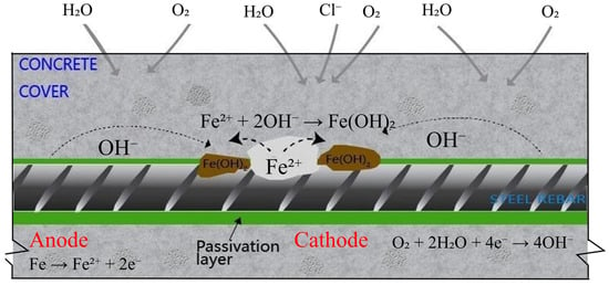
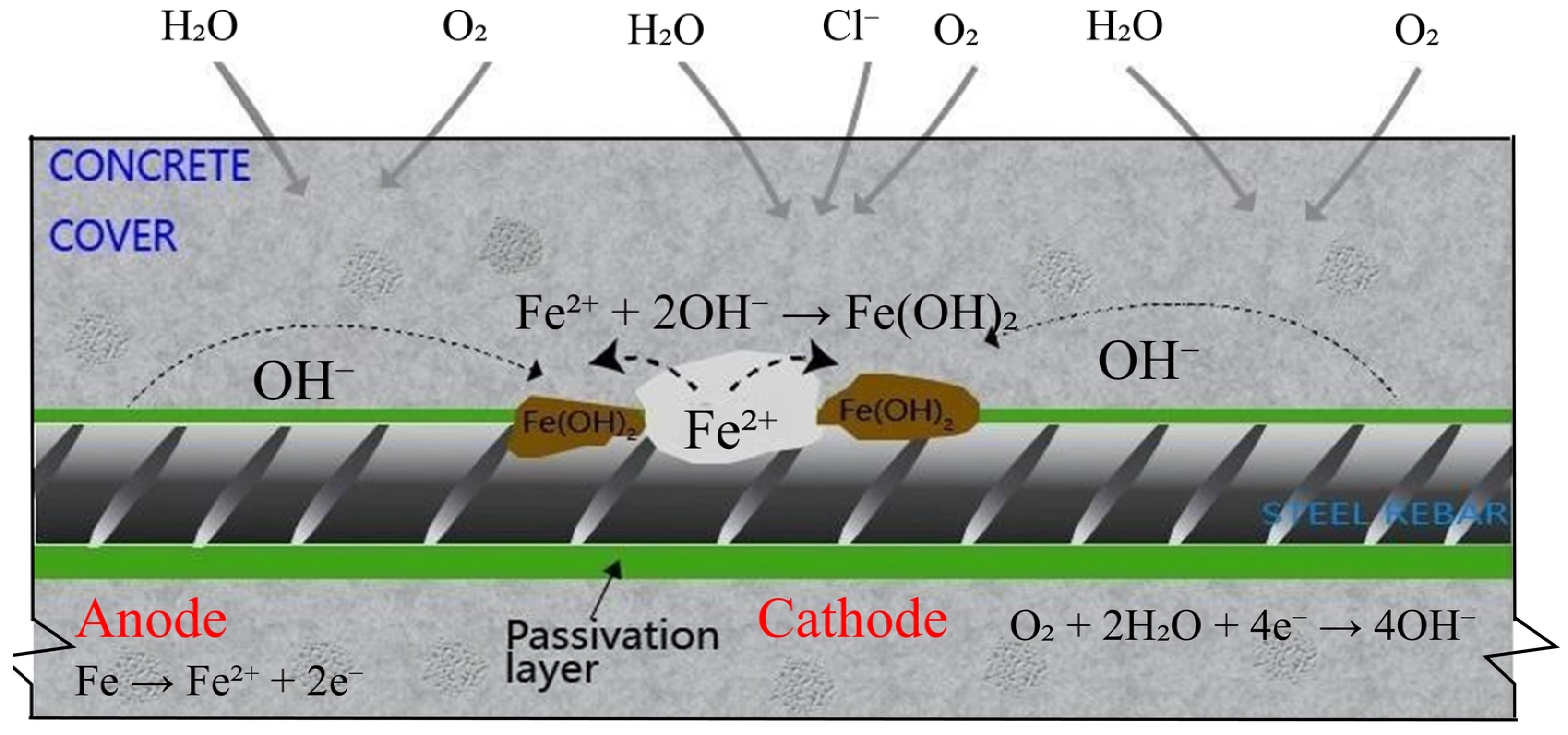
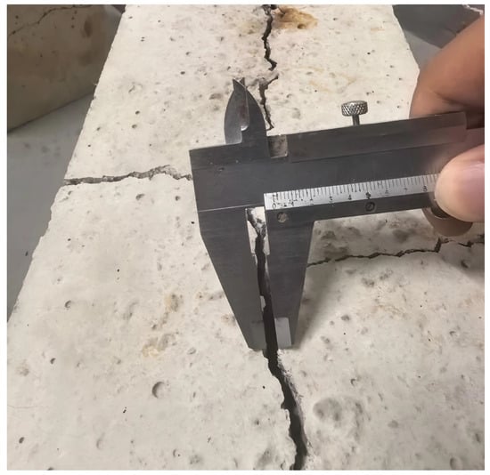
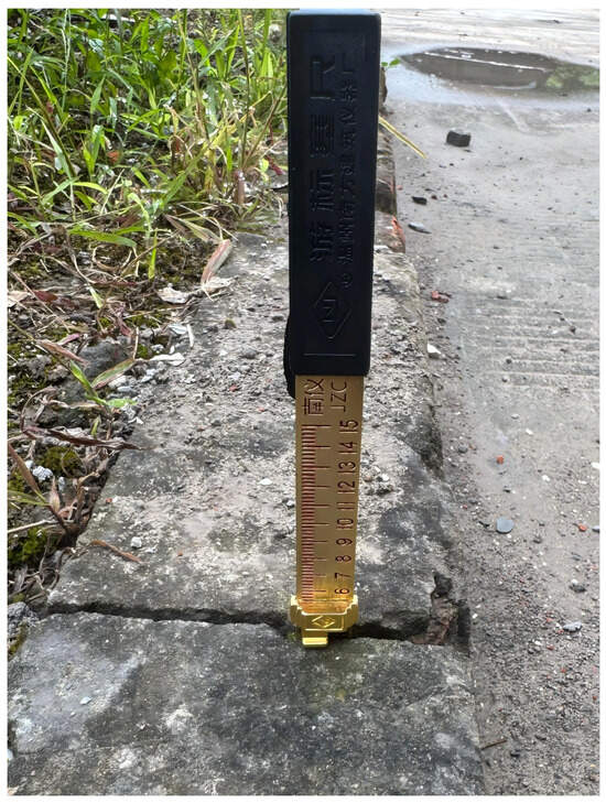
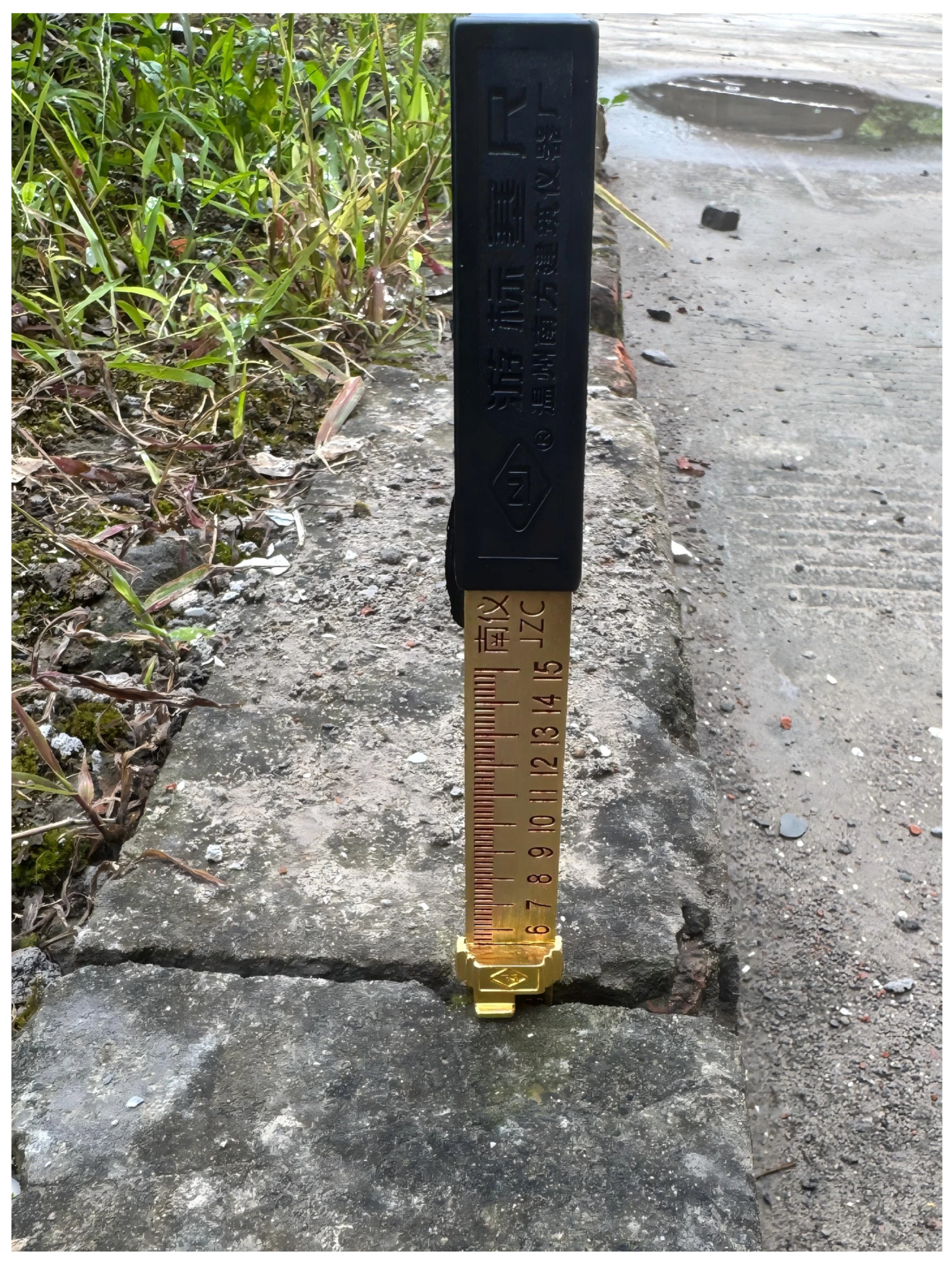
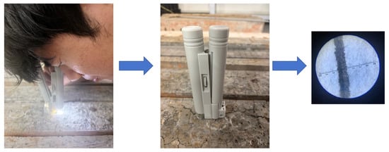
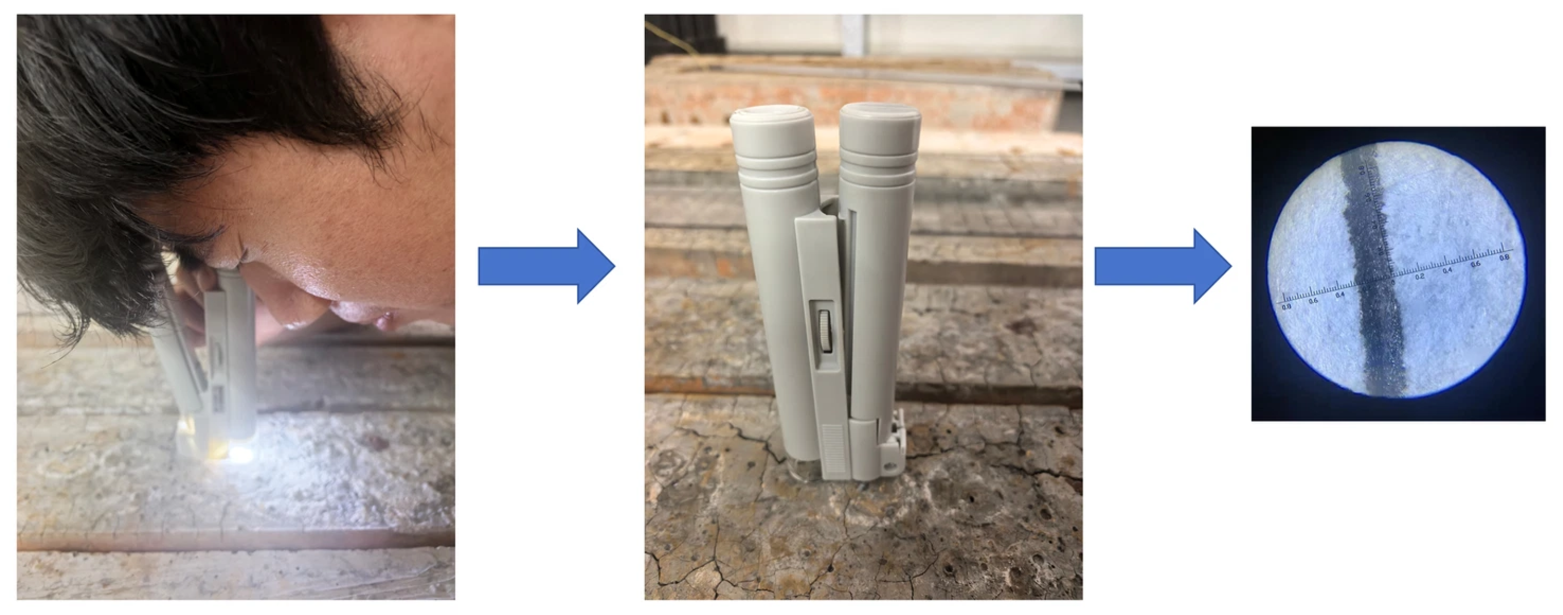
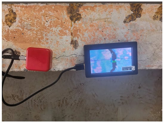
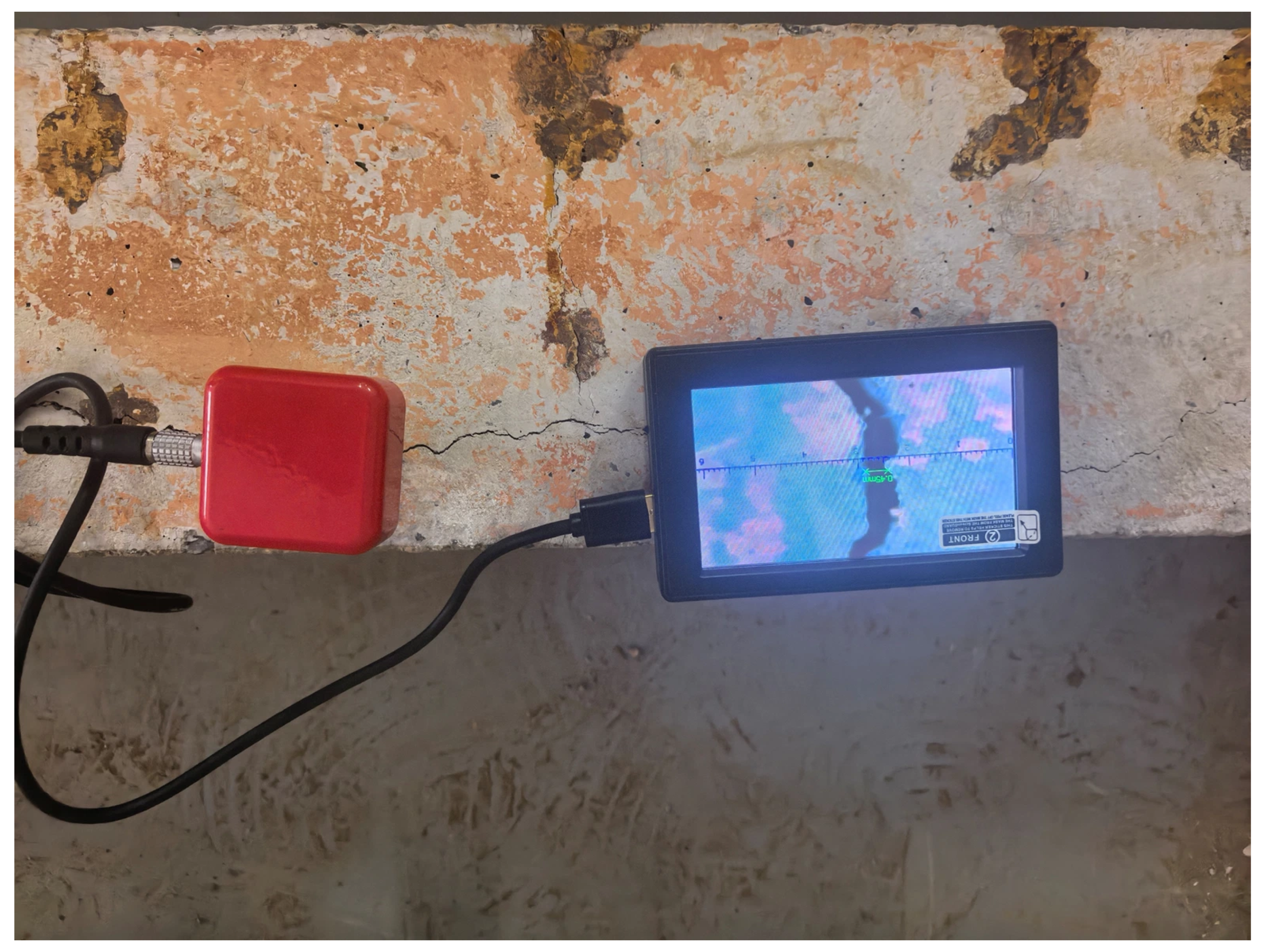
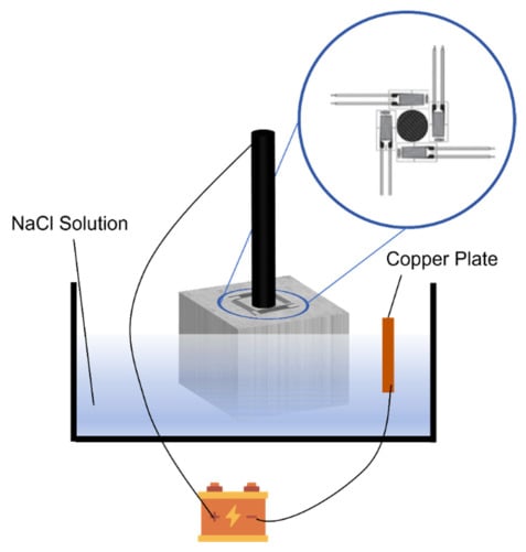
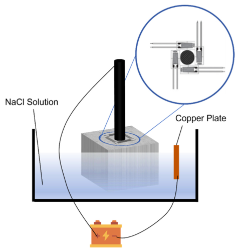
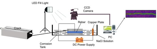
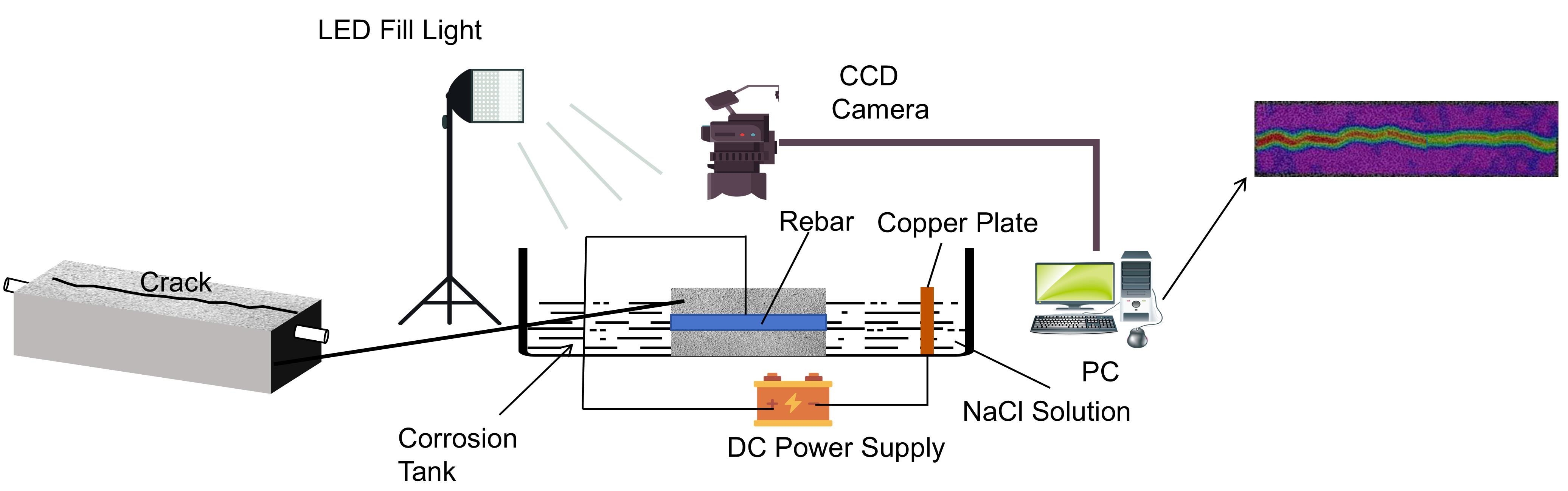
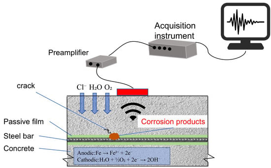
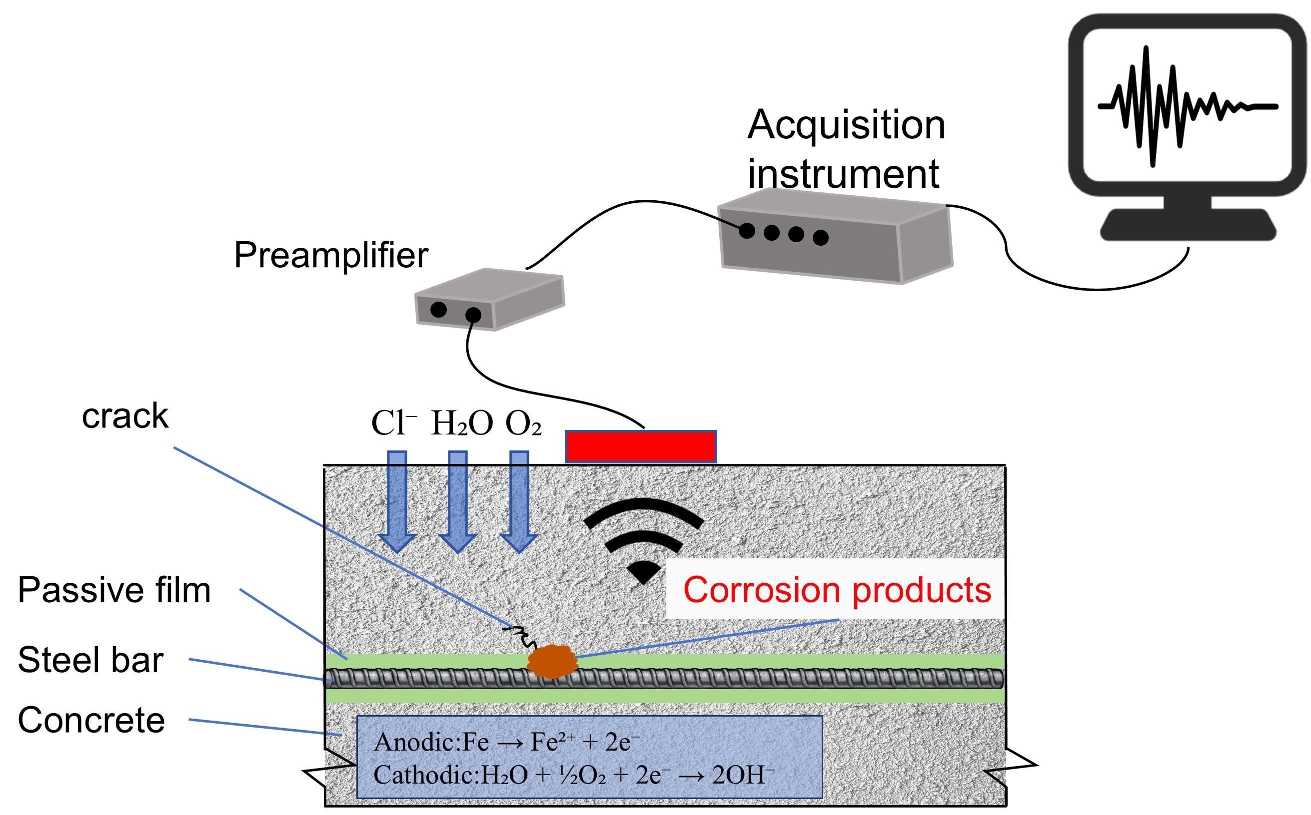
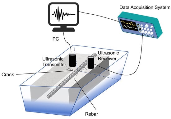
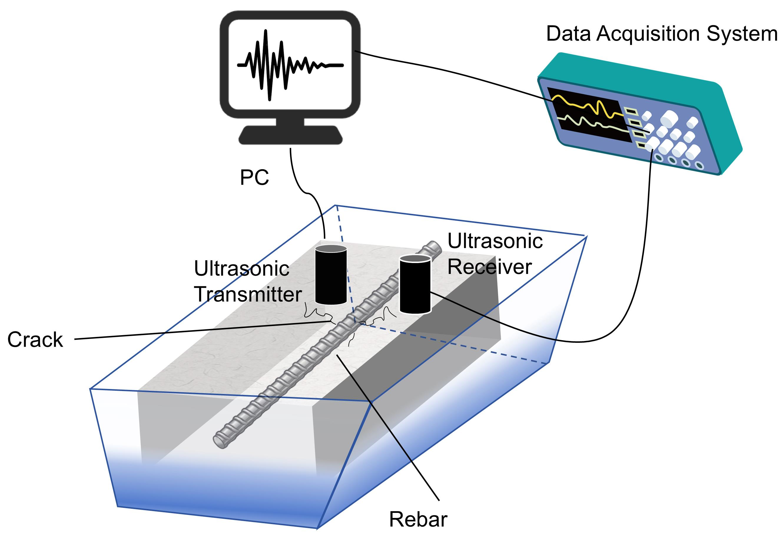
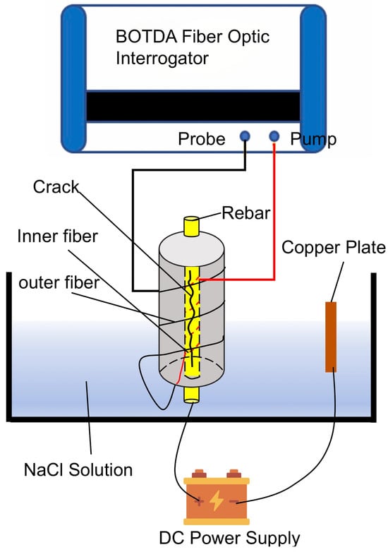
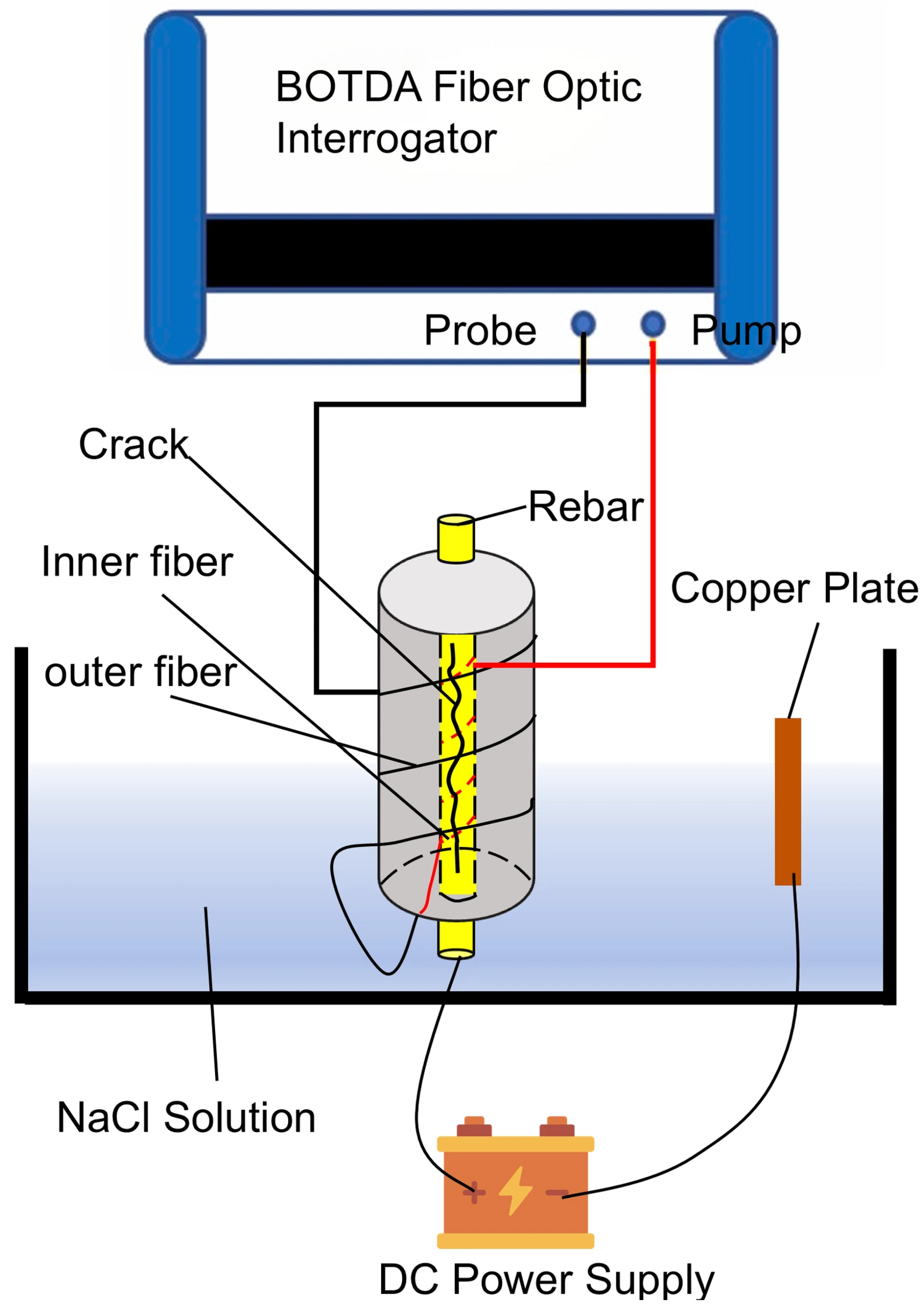
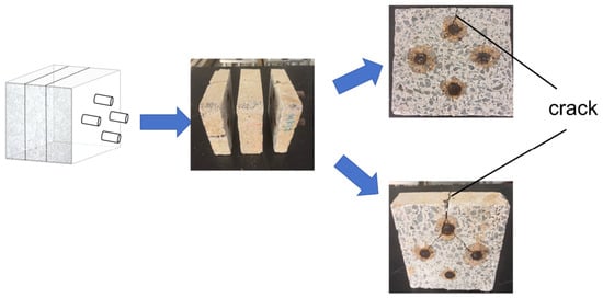
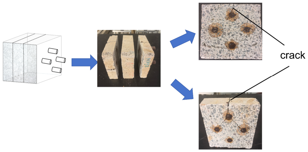
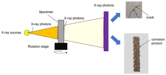
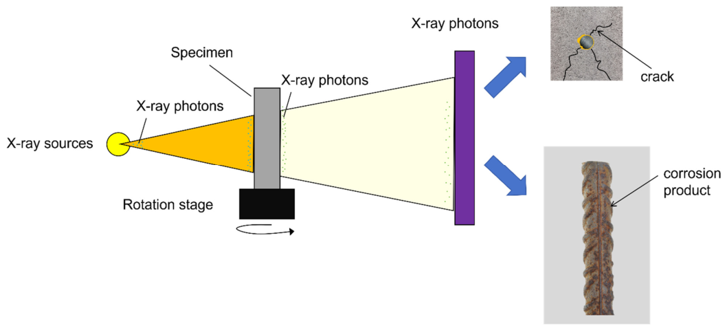
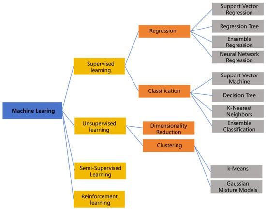
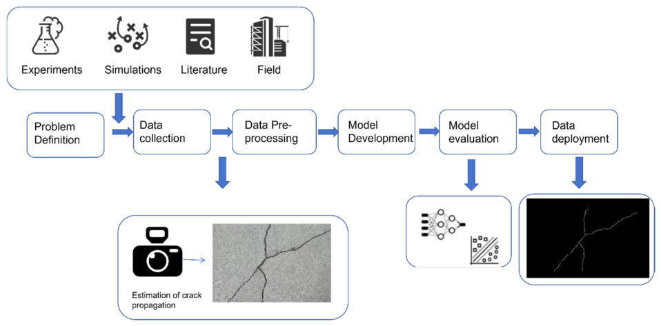

Disclaimer/Publisher’s Note: The statements, opinions and data contained in all publications are solely those of the individual author(s) and contributor(s) and not of MDPI and/or the editor(s). MDPI and/or the editor(s) disclaim responsibility for any injury to people or property resulting from any ideas, methods, instructions or products referred to in the content. |
© 2026 by the authors. Licensee MDPI, Basel, Switzerland. This article is an open access article distributed under the terms and conditions of the Creative Commons Attribution (CC BY) license.