


Abstract
This study proposes a productization framework to improve the design standardization of rural low-rise prefabricated residences (RLPR) in southern Jiangsu, China. The framework is built on three industrialized structural system prototypes: the prefabricated lightweight steel system (LSSCS), the composite cavity system (CCCS), and the rigid skeleton system (RSCS). At its core is a Python-based algorithmic workflow that automates and optimizes component system standardization. It automatically matches homestead dimensions to suitable layout types and applies combinatorial optimization to structural and enclosure components to minimize component variety. A case study validates the framework. From user-defined constraints, it generates a detailed parametric model and bill of materials, demonstrating a standardized, streamlined, and product-oriented RLPR design process.
1. Introduction
As global urban development advances and populations increasingly migrate from rural to urban areas, the developmental capacity, sustainability, and resilience of rural regions are in decline, causing rural recession to emerge as a widespread global challenge [1]. Rural areas act as crucial buffer zones during crises, relying on their independent economic system and abundant natural resources to ensure the supply of food and land, providing affordable labor and a sound consumer market for urban areas [2]. From a global perspective, nearly half of the population resides in rural areas [3]. As a developing country, China still has 35% of its population distributed in the vast suburbs and rural areas [4]. Improving the quality of the rural living environment is essential to the high-quality development of the Chinese economy. To address rural decline, China introduced the rural revitalization strategy, followed by a series of construction policies aimed at improving the rural living environment and restructuring rural industries. With the advancement of China’s rural revitalization strategy, rural housing construction faces challenges such as diversified functional demands, low construction efficiency, and high carbon emissions. The comprehensive application of adaptive design methods and prefabricated construction techniques, based on the principles of prefabrication and modular design, can significantly improve the flexibility, sustainability, and efficiency of residential design [5]. Prefabricated construction, with its industrial production advantages, has emerged as a solution. Prefabricated buildings substantially reduce construction water consumption, formwork usage, and construction waste, thereby supporting the sustainable development of the construction industry [6]. Prefabricated construction is therefore a key driver for upgrading the construction industry. The large-scale promotion of prefabricated buildings is also an important part of China’s construction industrialization process. In 2020, the Chinese government stipulated that the proportion of prefabricated buildings in the total area of newly added buildings should reach 15%, and by 2025, this proportion should be increased to 30% [7]. With the rapid development of prefabricated buildings in China, research on their thermal comfort, envelope performance, and structural systems continues to grow. However, the standardization and quantitative design of rural housing remain underexplored. The existing system has problems such as insufficient component standardization and low customization efficiency. Therefore, this paper attempts to summarize three rural housing structural systems widely used in the southern Jiangsu region of China from the perspective of architects based on the research team’s architectural project design practice. With these three systems as the core, a standardized design method suitable for low-rise rural housing is summarized. The method quantitatively designs spatial layout, opening, and depth and employs automation tools to match homestead dimensions with suitable housing types, thereby improving design efficiency and the standardization rate of building components.
2. Literature Review
2.1. Standardized Design and Optimization of Prefabricated Buildings
Prefabricated construction offers an efficient alternative to traditional construction methods, promotes the shift of construction activities from on-site work to factory-based production, and improves construction efficiency. The standardized design of prefabricated buildings follows the principle of fewer specifications and more combinations, and flexible combinations are made on the basis of standardization to create relatively rich and diverse designs to meet different functional requirements. At the same time, standardized spatial layout and relatively regular building forms can more conveniently construct performance optimization models. There is a natural internal consistency between the standardization of architectural design and the development of prefabricated buildings. Standardizing individual components enables component-level quality control, thereby ensuring the safety of entire building façades and spatial forms [8]. Yuan et al. [9] developed a simulation optimization design method for prefabricated building construction that considers multiple objectives and uncertain factors, achieving a reduction in construction costs and a shortened project duration. Wang et al. [10] constructed a dynamic evolutionary game model from the perspective of prefabricated building components to study the strategic choices made by manufacturers in carbon reduction optimization in order to provide an effective path forward. The optimization design of prefabricated buildings is different from traditional design, as this process can be advanced to the early stages of component production, transportation, assembly, and other design stages. Yang et al. [11] proposed an intelligent generation framework for prefabricated component assembly sequences based on graph databases and matrices using a genetic algorithm with a dual elite strategy to find the optimal assembly sequence and demonstrated its effectiveness with practical cases.
2.2. Research of Rural Residential Buildings
Rural housing is the most important building type in China’s rural areas. Compared with the urban living mode dominated by high-rise housing and row housing, rural housing is more decentralized, and the living and traffic conditions are relatively poor, presenting a different living mode, environment, and experience from the city. The facilities and environmental conditions of rural residences have improved considerably, though challenges remain. More and more rural residential buildings in China are equipped with modern facilities. The selection of building structures and the application of materials are also gradually changing from traditional to modern. In addition, concrete structures and wood structures have been widely used. Research on rural housing design can support the industrialization of rural construction and inform solutions for optimizing the acoustic, lighting, and thermal environments of rural dwellings. At present, research on rural housing mainly focuses on the thermal environment. Zheng et al. [12] conducted a subjective questionnaire survey and objective thermal environment testing on rural housing and villages from the perspective of elderly people in rural areas of Xi’an, providing a research foundation for the sustainable design of rural housing. Wang et al. [13] studied rural residential buildings in hot summers and cold winters in China and proposed a two-stage optimization design framework based on Rhino and Grasshopper combined with a genetic algorithm. The framework optimizes the width, depth, and solar energy gain coefficient of rural residential buildings according to the building energy consumption at different locations. Zou et al. [14] proposed an optimization method for rural housing in Inner Mongolia. They built a parametric model in Grasshopper and used the Ladybug and Honeybee plugins to simulate energy consumption and lighting. Finally, they established a wall database to realize the visualization of material properties and construction methods. There are also some studies trying to analyze the planning of rural land resources from the perspective of land. Wang et al. [15] applied symbiosis theory to construct a rural multi-symbiosis system and verified a public space construction strategy based on the reuse of idle land.
3. Methodology
Based on three common structural systems for RLPR, this paper proposes and implements a product-oriented design process guided by architectural design principles. The optimization process uses a Python-based (V3.8) preprocessing step to align the optimized structural configuration with the architectural design, yielding a fully product-oriented workflow in the southern Jiangsu region.
3.1. Classification Methods for Component Systems of Three Types of RLPR Products
3.1.1. Prefabricated Lightweight Steel Structural Components System (LSSCS)
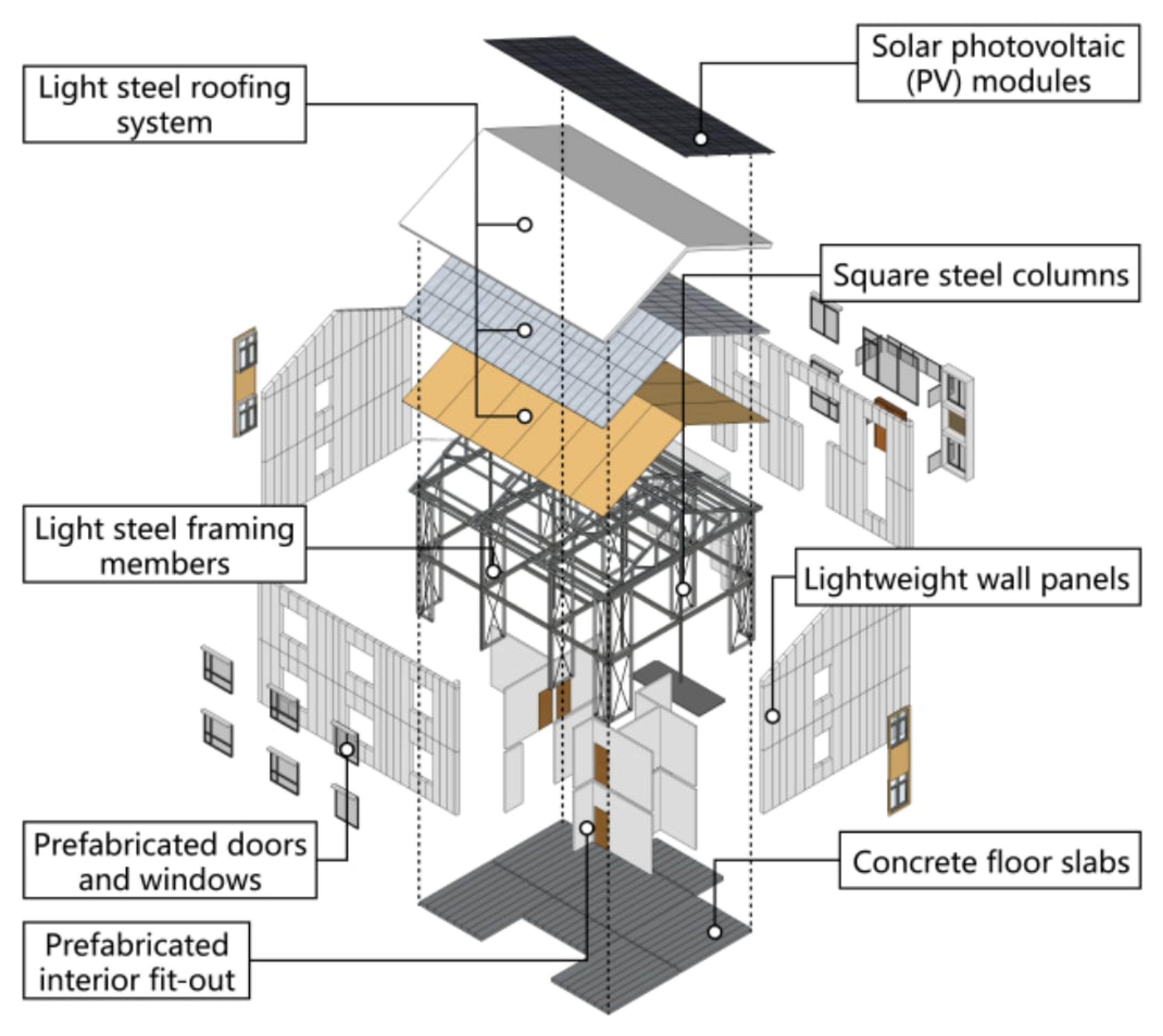
The LSSCS offers significant advantages, including expedited on-site construction and favorable reusability of its components. However, an inherent limitation of this frame-based system is its restricted span capability, which may not accommodate designs requiring large, variable interior spaces. Consequently, as outlined in the prior customization workflow, clients with substantial spatial flexibility requirements are advised to consider alternative systems, such as the prefabricated rigid skeleton. Despite this limitation, the lightweight steel system excels in modular design. Its components can be efficiently expanded and combined, allowing for considerable freedom and flexibility in the arrangement of modular elements, such as external balconies. Figure 1 shows a schematic diagram of a typical LCCSS system. The LSSCS reduces on-site labor and shortens the construction cycle, which is particularly suitable for the compact two-bay and three-bay rural residences common. The light steel members are typically produced as uniform modular units, so component inventories can be simplified and reused across different housing products in the southern Jiangsu region.
Figure 1.
Schematic illustration of the LSSCS for a prefabricated rural residential product.
3.1.2. Rigid Skeleton Components System (RSCS)
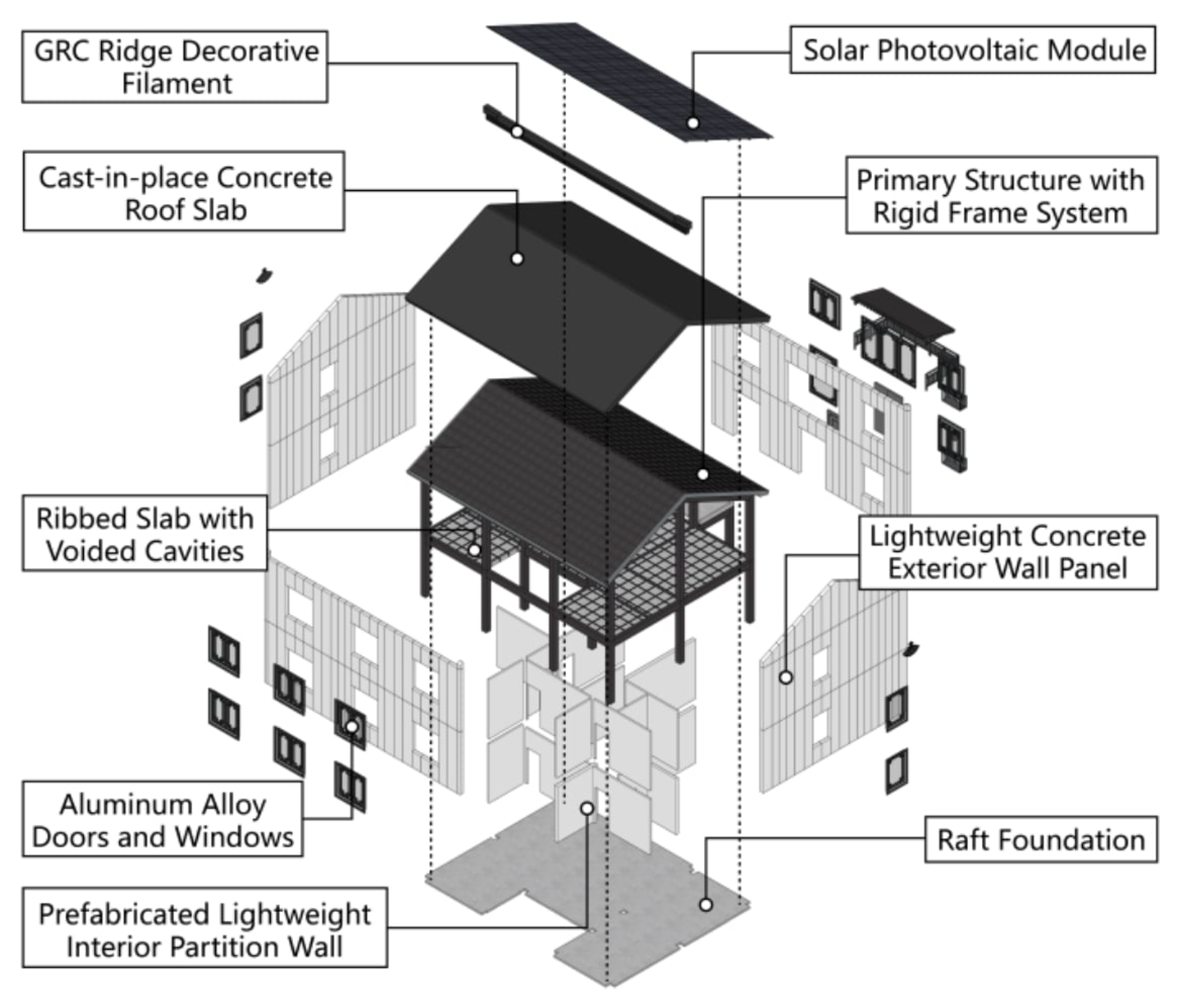
The RSCS can meet the user’s demand for large space. Therefore, in the above customization process, when the user requests large space, only the prefabricated rigid skeleton structural system can be selected. It relies on rigid beam–column connections to achieve large spans with few interior load-bearing walls, thereby providing the open and flexible floor plans that the lightweight steel frame cannot support. Figure 2 shows a schematic diagram of a typical RSCS system. By transferring loads to a primary skeleton, interior partitions can be freely placed or removed according to the household’s living needs, which makes the system well suited to multi-functional living–dining areas. A trade-off is that, compared with the LSSCS, the rigid skeleton prioritizes structural performance over component standardization, so its detailing requires closer coordination with the spatial design.
Figure 2.
Schematic diagram of RSCS for prefabricated rural residential product.
3.1.3. Composite Cavity Components System (CCCS)
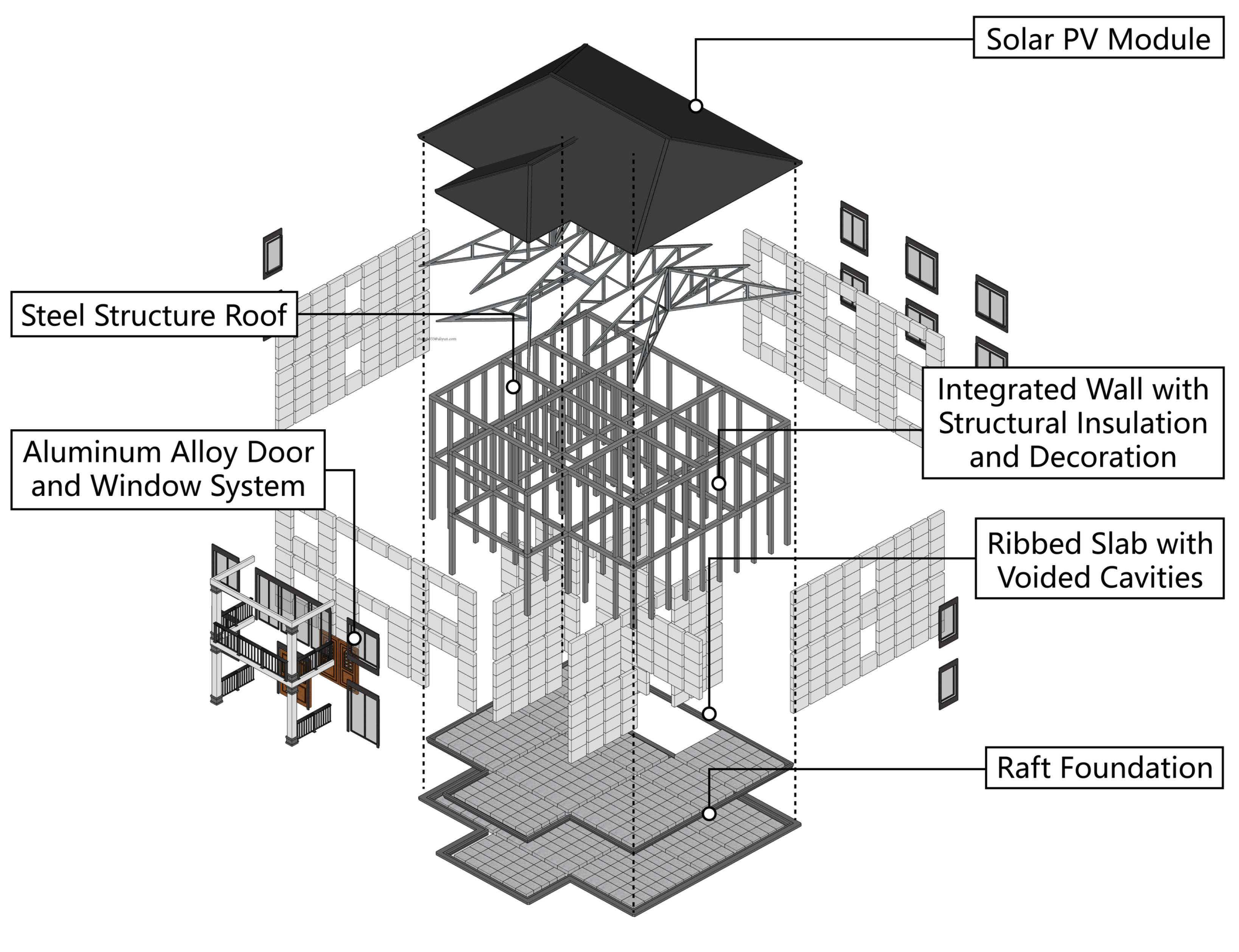
Compared to the other two types of prefabricated building systems, the possibility of free and flexible arrangements of structural components in CCCS is relatively low. Due to the need to meet the layout of fixed modular structural component units, it is suitable for households with high requirements for spatial privacy. The structural modules have strong repeatability and expandability, making it easy to form standardized group spaces. The cavity units integrate functions such as thermal insulation and service conduits within factory-finished panels, which improves construction quality and reduces on-site wet work. Because the modules follow fixed dimensional rules, they are well suited to forming repeated, rhythmical façades and to households that prioritize privacy and a clearly defined room layout over spatial openness. Figure 3 shows a schematic diagram of a typical CCCS system.
Figure 3.
Schematic diagram of CCCS for prefabricated rural residential product.
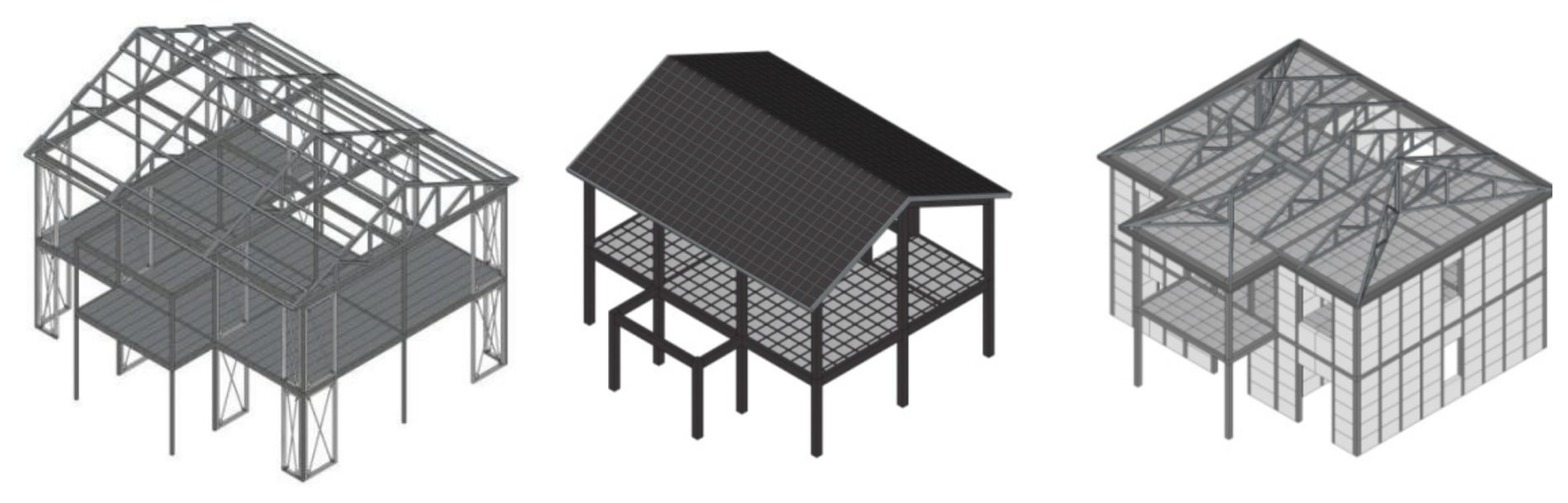
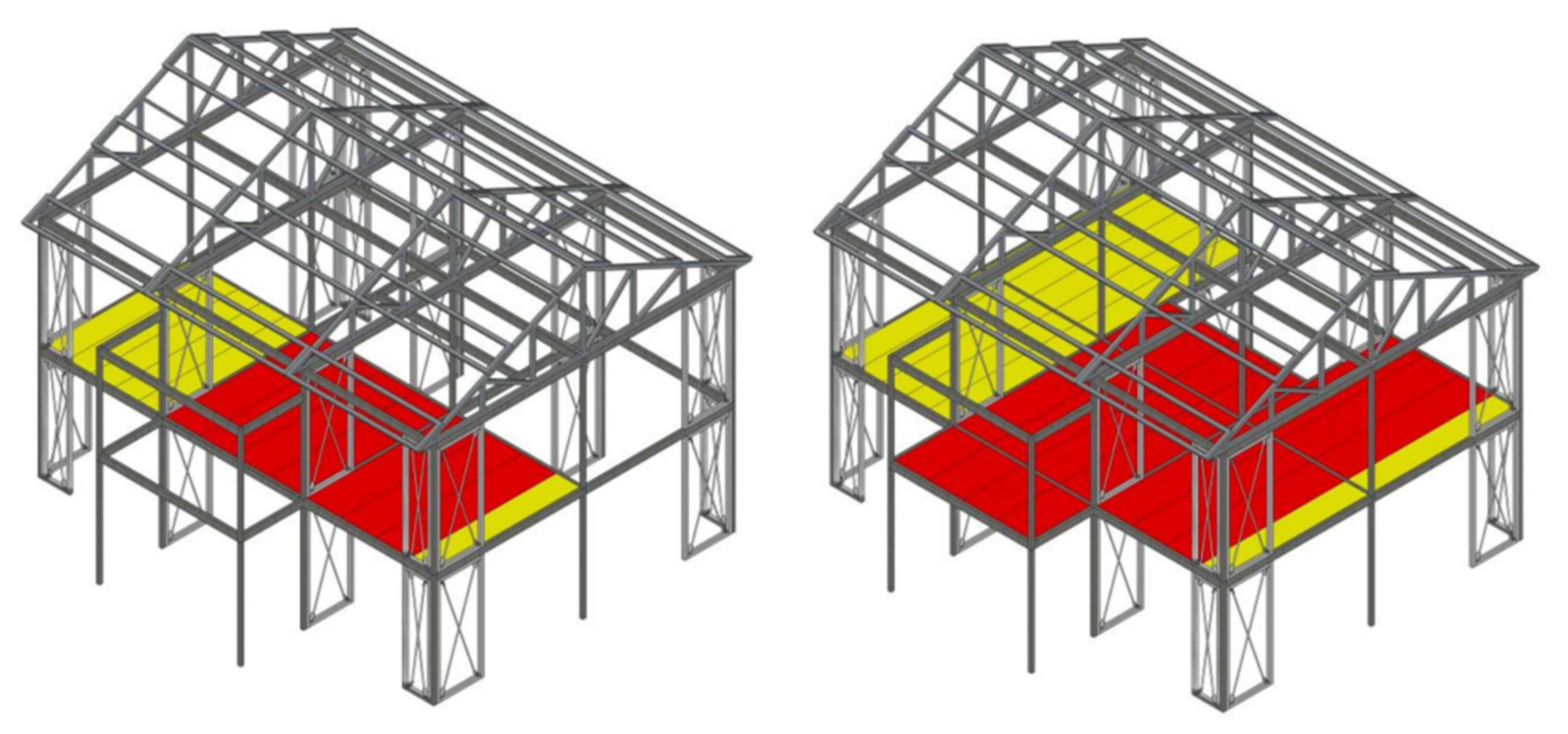
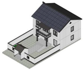
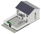
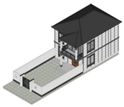
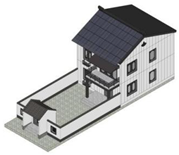
The standardized product system for RLPR is designed to adapt to homesteads of various sizes. Figure 4 shows schematic diagrams of the structural components of the three systems. Rural homesteads are relatively compact, and the courtyards enclosed by the residences are often small. The residences themselves primarily feature two-bay and three-bay layouts. The architectural design styles mainly include eclectic, modern, and Chinese vernacular styles. Table 1 below provides examples of rural residences with different numbers of bays and different architectural design styles.
Table 1.
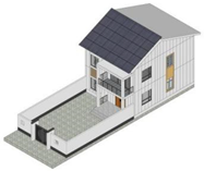
Product sequence of three-bay and two-bay systems.
Figure 4.
A Classification of three prefabricated structural systems for residential housing.
The standardized products in rural areas of the southern Jiangsu region are based on a standardized component system to form flat spatial units, which can be combined with each other to form double or row style rural residential groups. Standardized product plan space units can ensure the unified and coordinated appearance of rural groups, achieving the goal of overall standardized design. Moreover, because the standardized spatial units can be extended or reduced and optional functional modules added or removed according to user needs, the rich and rhythmic form in the southern Jiangsu region can be achieved. The specific design pattern is as follows.
3.2. Method for Axis Positioning of the Standardized Product Component System
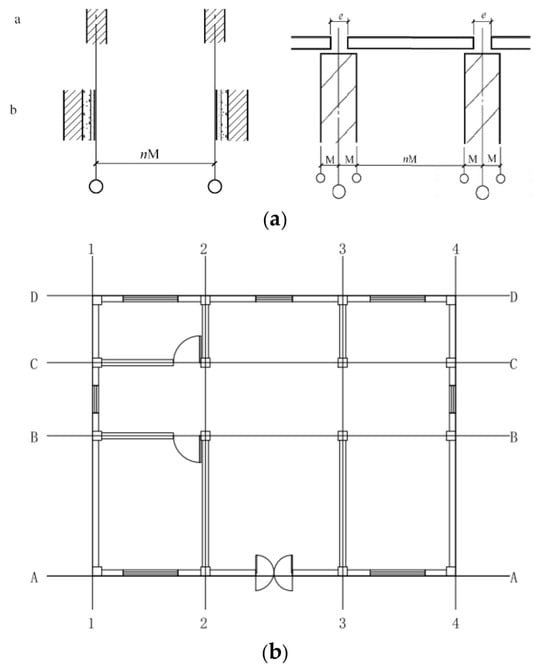
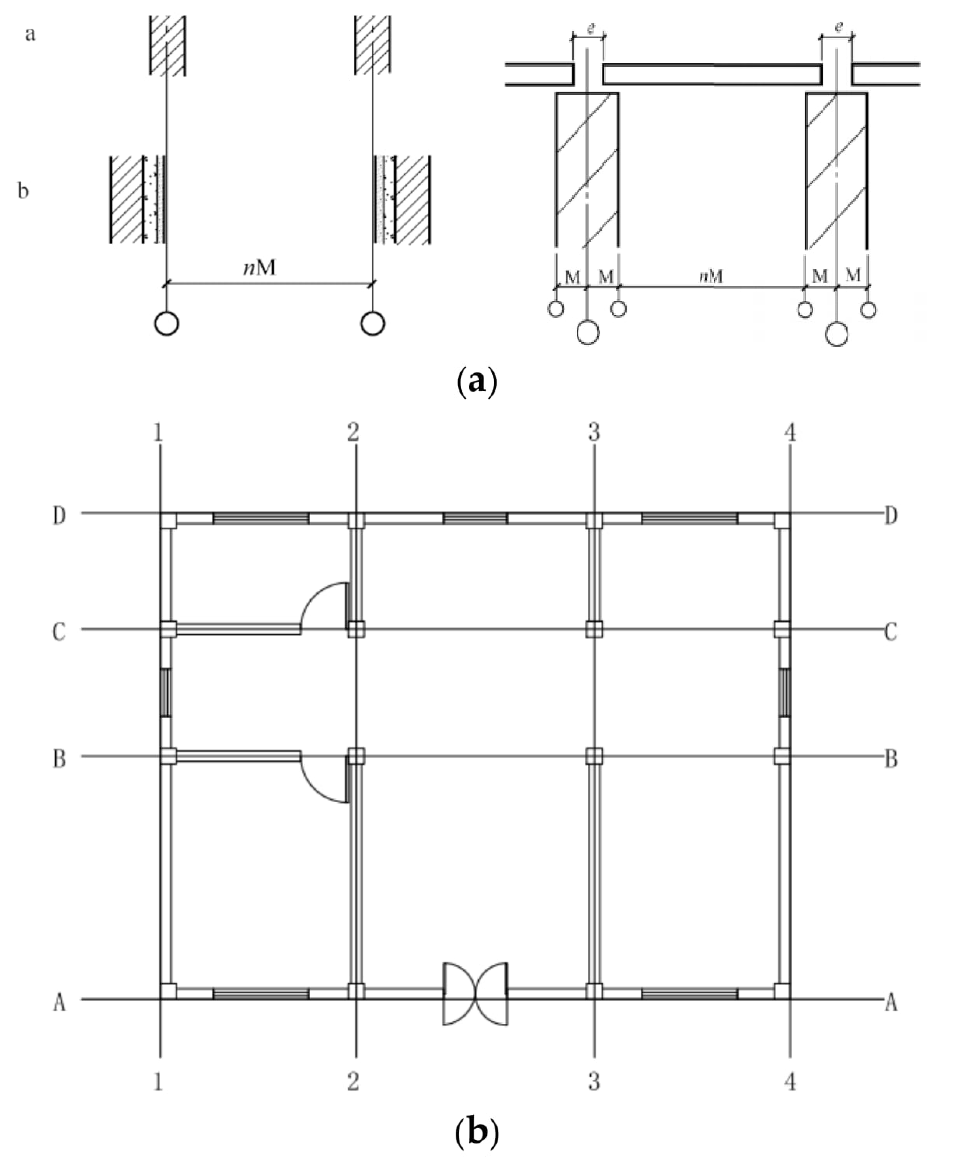
The optimization process for standardized RLPR products requires the adoption of a relatively rational positioning method for the component system. In this context, the Code for Modular Coordination in Building (GB/T 50002-2013) [16] provides clear solutions for the axial positioning related to building structures and envelope systems. As illustrated in the figure below, three positioning methods can be employed: centerline positioning, interface positioning, and a method combining both centerline and interface positioning (Figure 5).
Figure 5.
Schematic diagrams of the component system positioning method: (a) combined centerline-and-interface positioning; (b) axis positioning of the layout plan.
The positioning method for the planar axis of the residential product layout in this study is based on the principles of convenience in the design and construction of standardized component systems. Therefore, a combination of the above positioning methods is chosen. In order to facilitate the separation and positioning of various types of component systems, the following specific positioning method should be followed (Figure 5).
In order to meet the matching design process of homestead land, the outer edges of the enclosure structures on both sides of the building should be consistent with the size of the homestead land. Therefore, the outer enclosure edge interface is used for positioning to avoid the outer enclosure wall exceeding the size range of the homestead land during further design. The structural component system of the middle part of residential products is usually on the same axis as the internal partition wall component system. In order to facilitate the calculation of unit size and the design of internal space, this part adopts the center positioning method.
3.3. Product Design Optimization Process
The customization process for RLPR products necessitates efficient, real-time collaboration among designers, on-site homestead conditions, and the personalized requirements of the client’s family. Conventional communication methods such as telephone, email, and face-to-face meetings are difficult to efficiently communicate and clarify information and are prone to information asymmetry between users and different professionals. Such communication methods have too many variable factors that deviate from the goal of customized production of rural prefabricated housing products. Therefore, in the current era of the rapid development of the Internet, it is more necessary to communicate using the Internet communication platform and customized programs that can be controlled layer by layer to clarify the design needs and goals, gradually confirming the current information and clarifying the next step of deepening design behavior. In this study, we attempt to match the needs of users to a certain extent using established functional product types in order to efficiently complete the customized design process and improve the efficiency of the design, production, transportation, and construction cycle of standard product component systems.
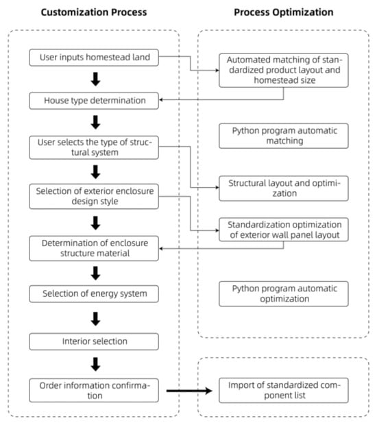
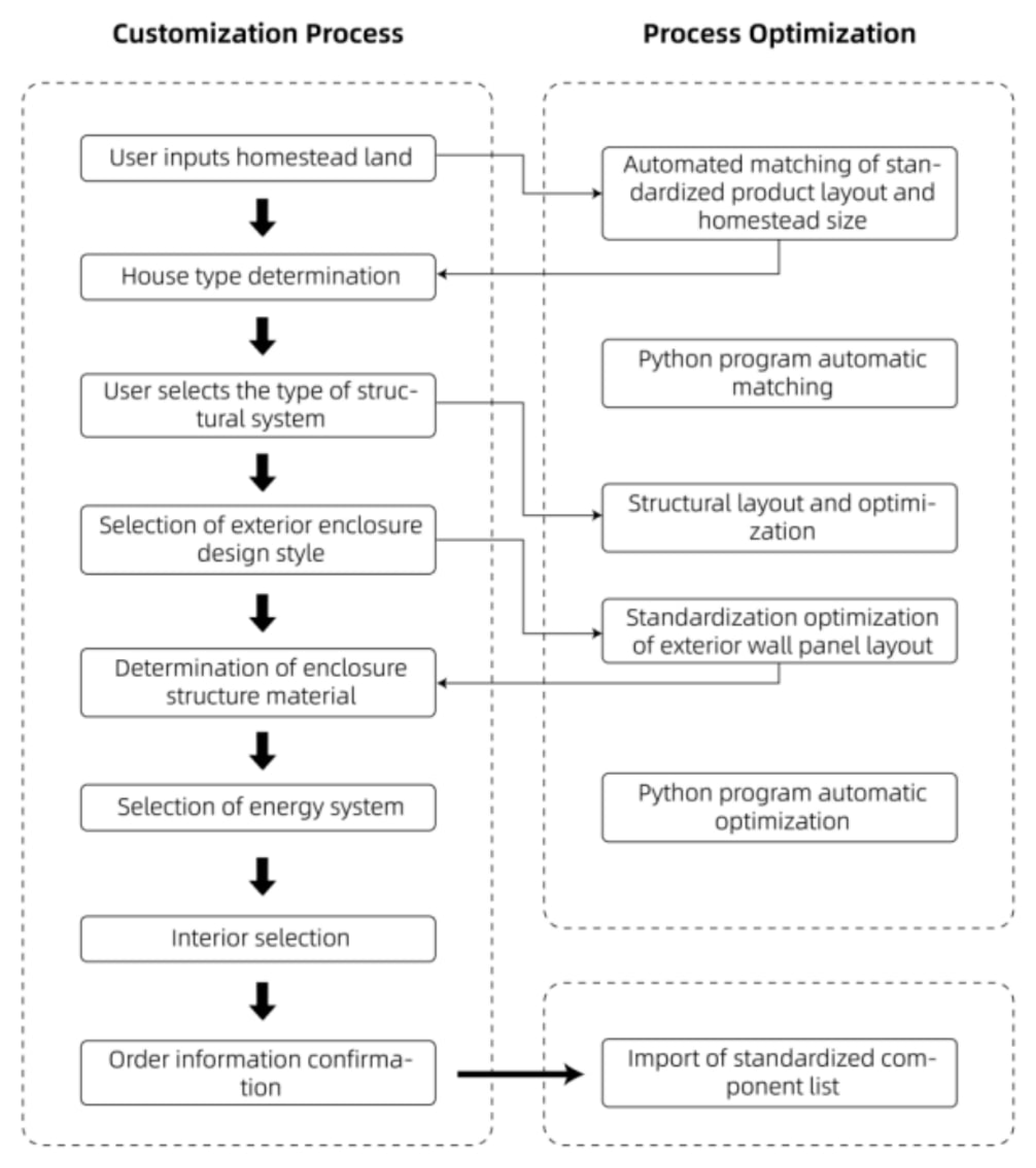
This section develops a Python-based (PyCharm, V2024.1) workflow that automates component system data matching and optimization across the customization stages, addressing (1) homestead matching, (2) the selection and standardization of structural components, and (3) the standardization and optimization of prefabricated exterior wall panels. The process is consistent with and interactive with the customized product architecture described above and is summarized in Figure 6.
Figure 6.
Customization of rural prefabricated residential products and optimization processes using Python-based programs.
Ultimately, a list of standardized structural component systems, standardized enclosure component systems, and standardized energy component systems can be obtained based on user selection. The prefabricated interior component system, by contrast, requires further detailed consultation between designers and clients before it can be finalized.
4. Case Study
4.1. Case Prototype
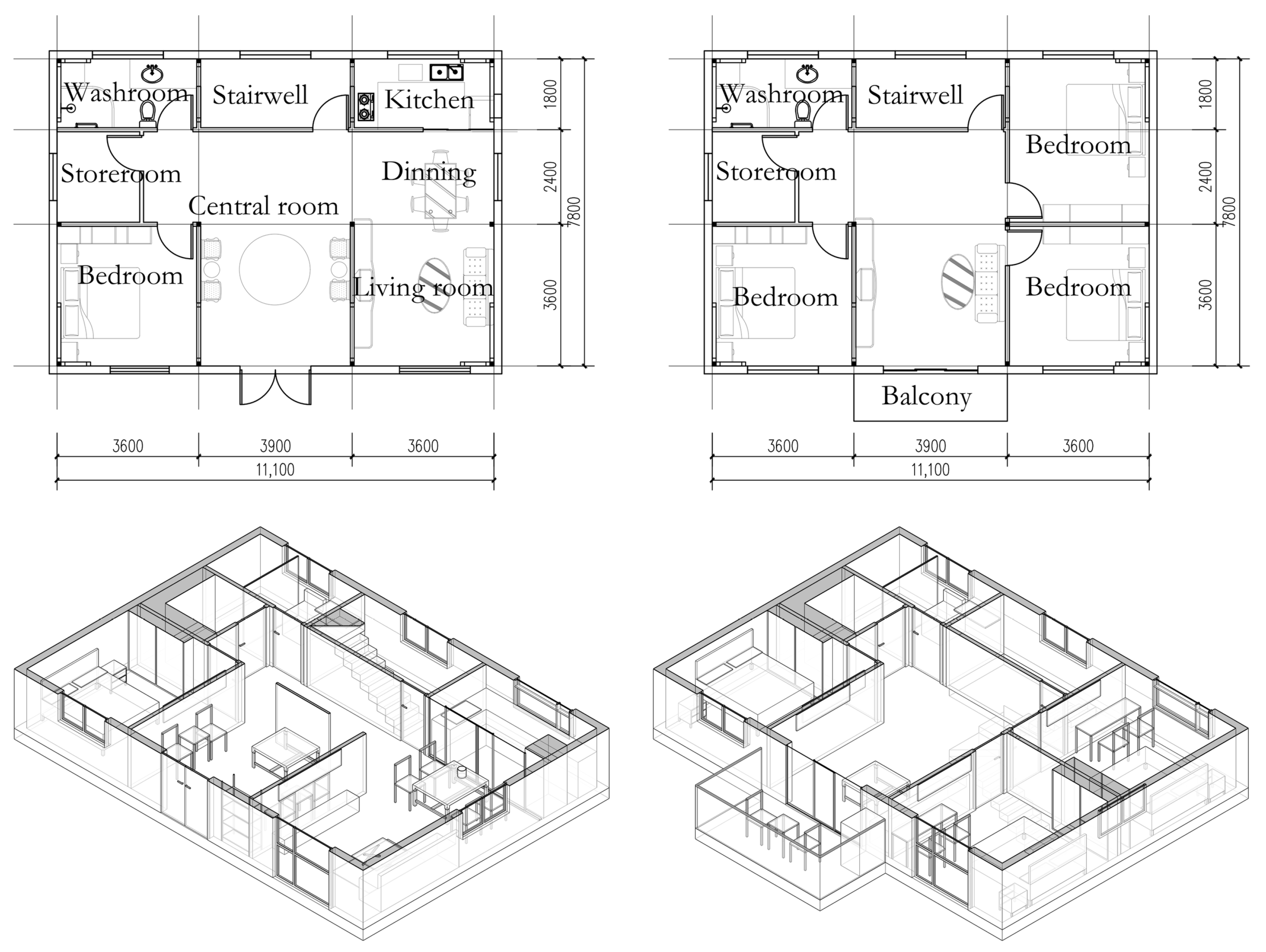
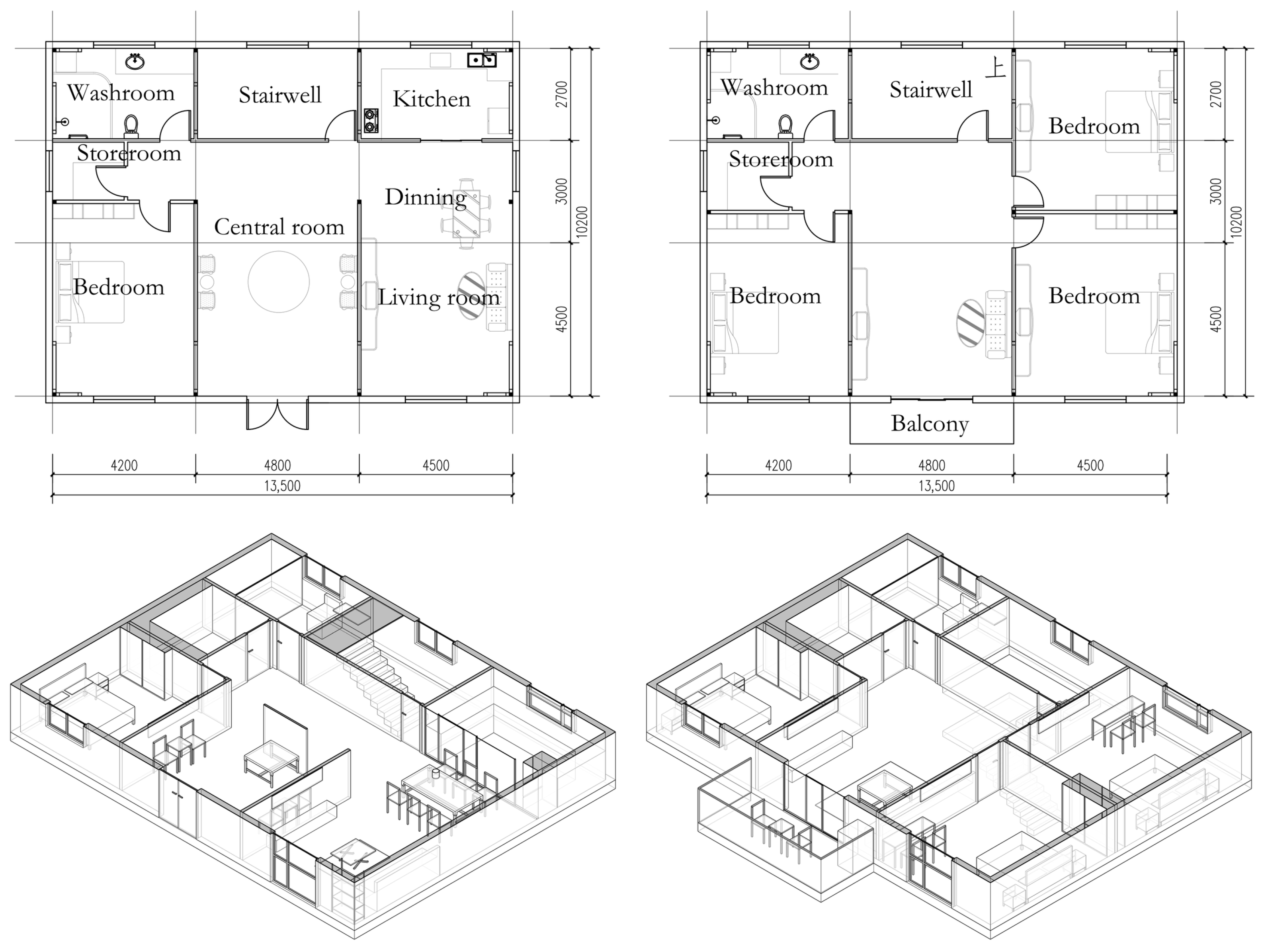
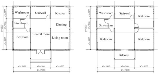
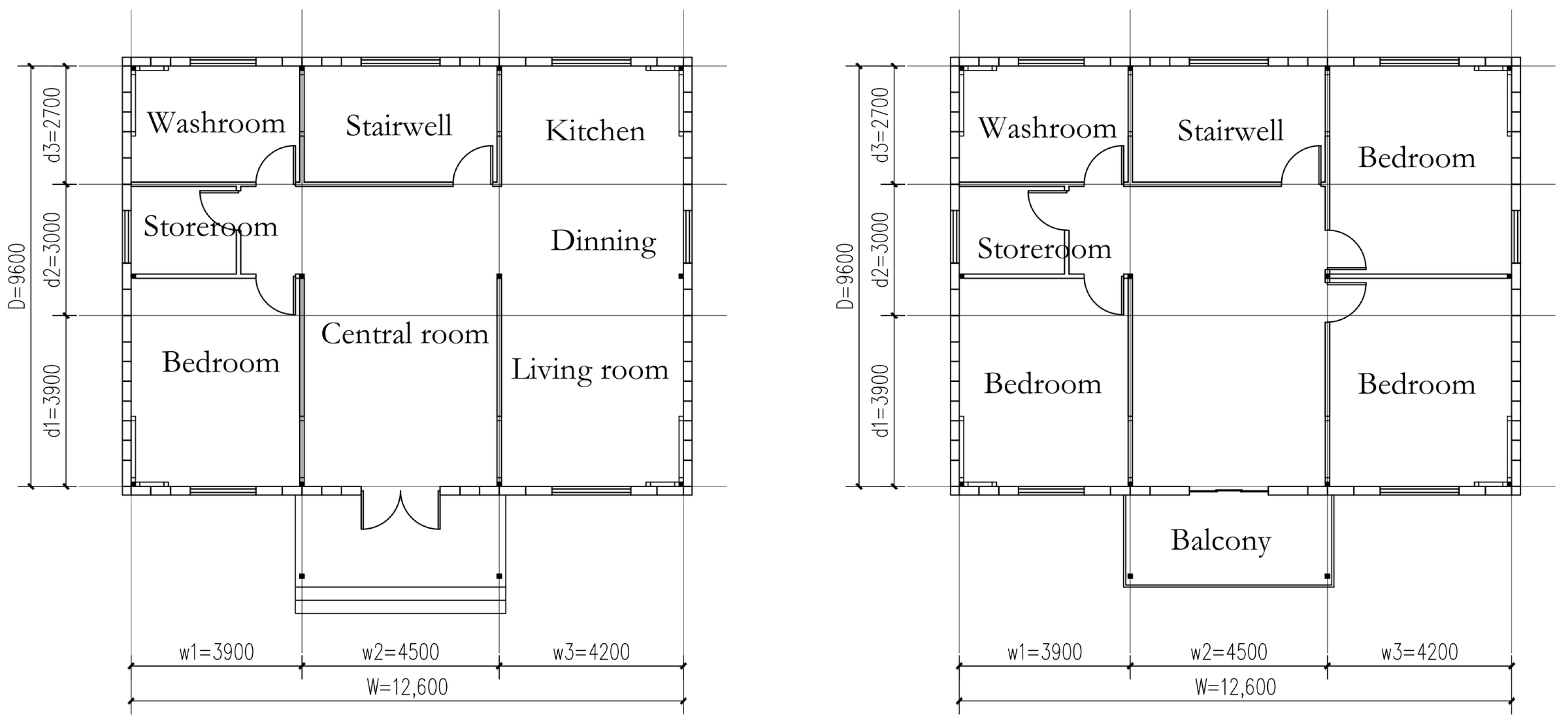
This paper takes a low-rise residential layout suitable for the climate, customs, and functional requirements of rural areas along the eastern coast of China as a prototype for research. The internal space of standardized rural residential products is developed based on efficient streamline organization, the rationality of functional space layout, and the flexibility of internal functional space and furniture combination arrangements. The following is the internal functional space diagram of the prototype of the rural prefabricated residential product. Four representative apartment products were derived by assigning the lower and upper bounds of each dimensional parameter, as detailed below.
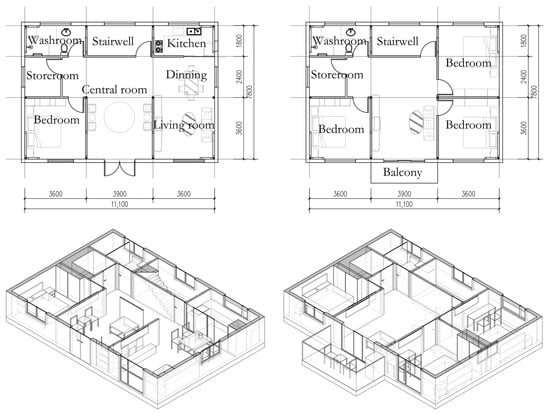
(1) Compact three-bay, two-story RLPR product (Type S-3-2) (Figure 7).
Figure 7.
Internal functional diagram of S-3-2 apartment product.
The S-3-2 RLPR product is configured with a compact set of dimensions. The width (W) and depth (D) are determined by the sums of their constituent segments: W = w1 + w2 + w3, where w1 = 3600 mm, w2 = 3900 mm, and w3 = 3600 mm; and D = d1 + d2 + d3, where d1 = 3600 mm, d2 = 2100 mm, and d3 = 1800 mm.
(2) Spacious three-bay, two-story RLPR product (Type L-3-2) (Figure 8).
Figure 8.
Internal functional diagram of L-3-2 apartment product.
The L-3-2 RLPR residential product is configured with an expanded set of dimensions. W and D are determined by the sums of their constituent segments: W = w1 + w2 + w3, where w1 = 4200 mm, w2 = 4800 mm, and w3 = 4500 mm; and D = d1 + d2 + d3, where d1 = 4500 mm, d2 = 3000 mm, and d3 = 2700 mm.
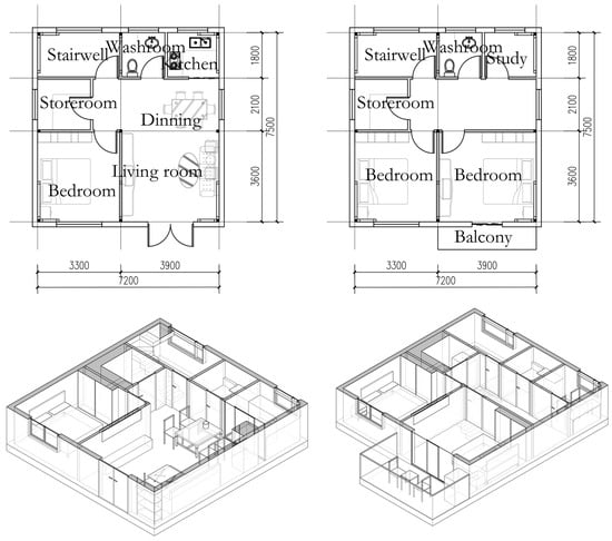
(3) Compact two-bay, two-story RLPR product (Type S-2-2) (Figure 9).
Figure 9.
Internal functional diagram of S-2-2 apartment product.
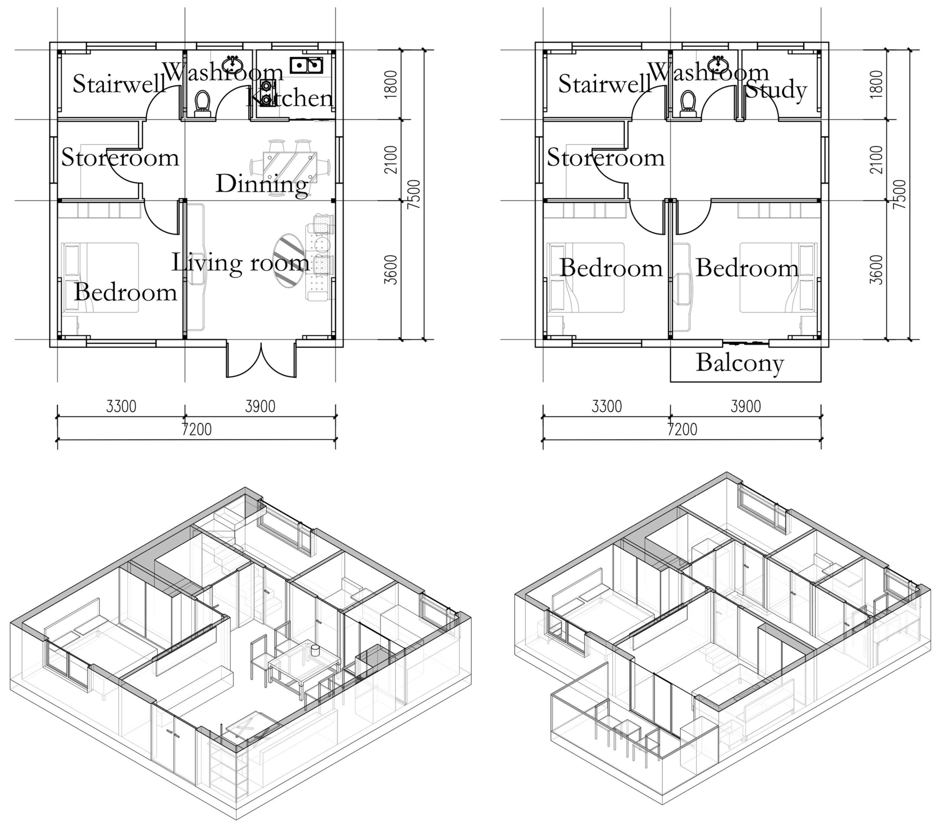
The S-2-2 RLPR product is configured using the minimum values of its parametric dimensional system. W and D are determined by the sums of their constituent segments: W = w1 + w2, where w1 = 3300 mm and w2 = 3900 mm; and D = d1 + d2 + d3, where d1 = 3600 mm, d2 = 2100 mm, and d3 = 1800 mm.
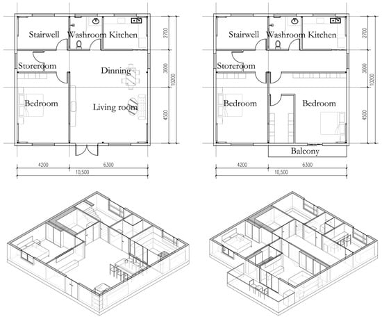
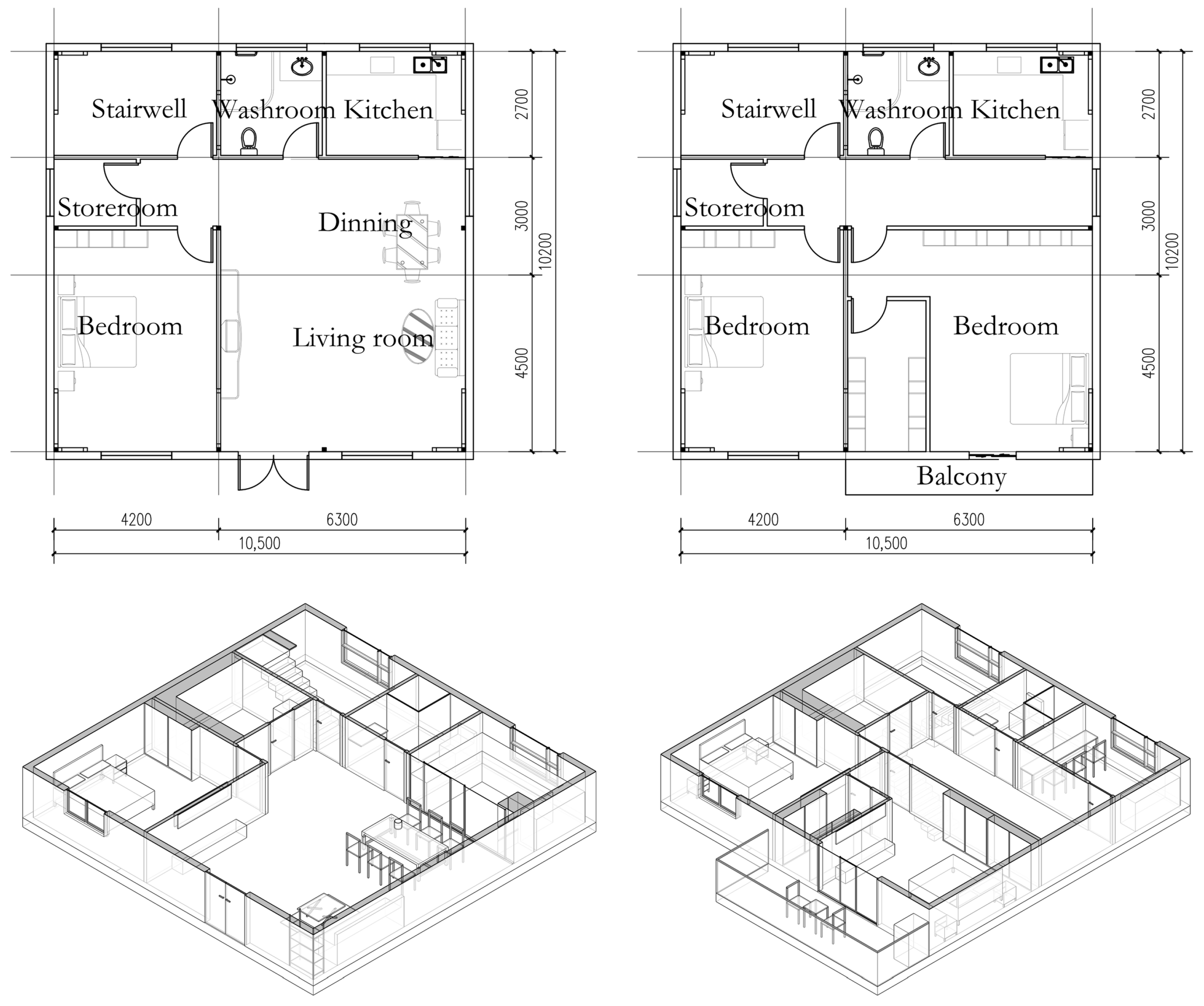
(4) Spacious two-bay, two-story RLPR product (Type L-2-2) (Figure 10).
Figure 10.
Internal functional diagram of L-2-2 apartment product.
The L-2-2 RLPR product is configured using the maximum values of its parametric dimensional system. W and D are determined by the sums of their constituent segments: W = w1 + w2, where w1 = 4200 mm and w2 = 6300 mm; and D = d1 + d2 + d3, where d1 = 4500 mm, d2 = 3000 mm, and d3 = 2700 mm.
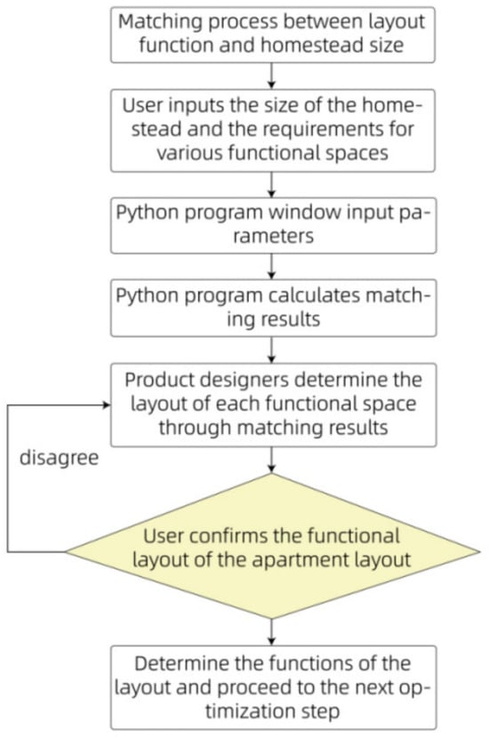
4.2. Automatic Calculation and Matching of Dimensions Between RLPR Products and Homesteads
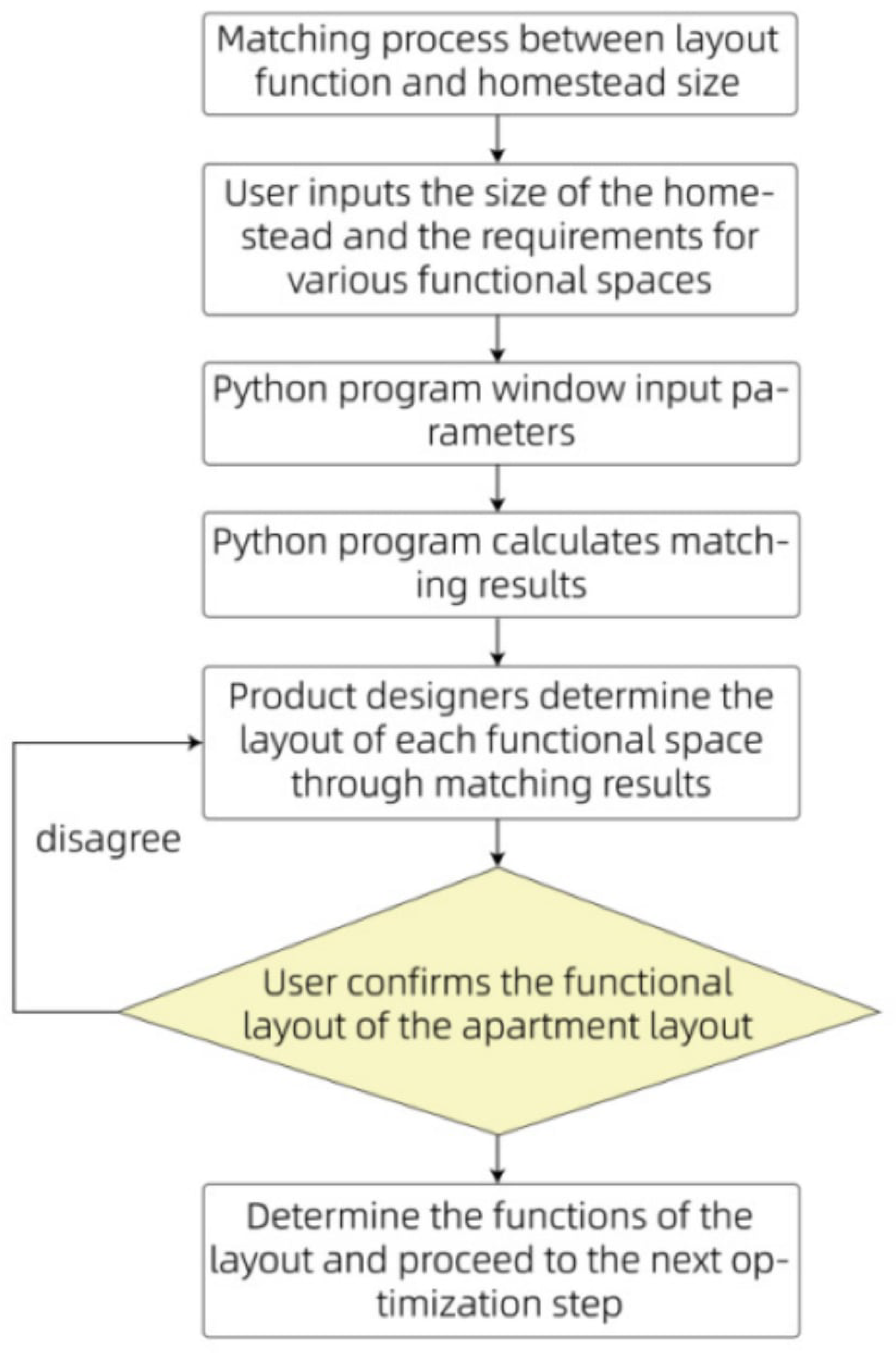
The matching design between standardized RLPR products and homesteads in the southern Jiangsu region is based on the basic principles of rural planning and homestead division in this area. This rural standardized residential product is divided into three-bay and two-bay types in terms of size and corresponding layout design. Therefore, the use of Python-based programs also revolves around these two types of products (Figure 11).
Figure 11.
Flow chart for matching house function with homestead size.
4.2.1. Parameterization Principles for the Matching Design of Homestead Size and Prefabricated Residential Products
The selection and design of prefabricated rural residential products in the southern Jiangsu region are intricately linked to the planning conventions and spatial dimensions of homestead parcels. Field investigations reveal that the overall layout of these homesteads typically features a relatively compact frontage (width) and an elongated depth. A cross-sectional survey of user preferences indicates that the majority of residents opt for a residential floor area between 100 m2 and 300 m2, with dwellings exceeding 300 m2 constituting less than 20% of the market preference. Furthermore, the predominant choice involves the number of floors. Consequently, the dimensional parameters of the proposed prefabricated housing product layouts should be calibrated to align with these empirically derived spatial patterns and user preferences.
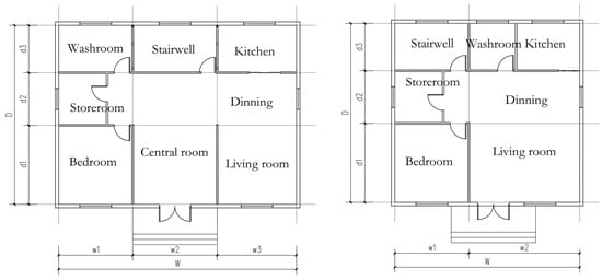
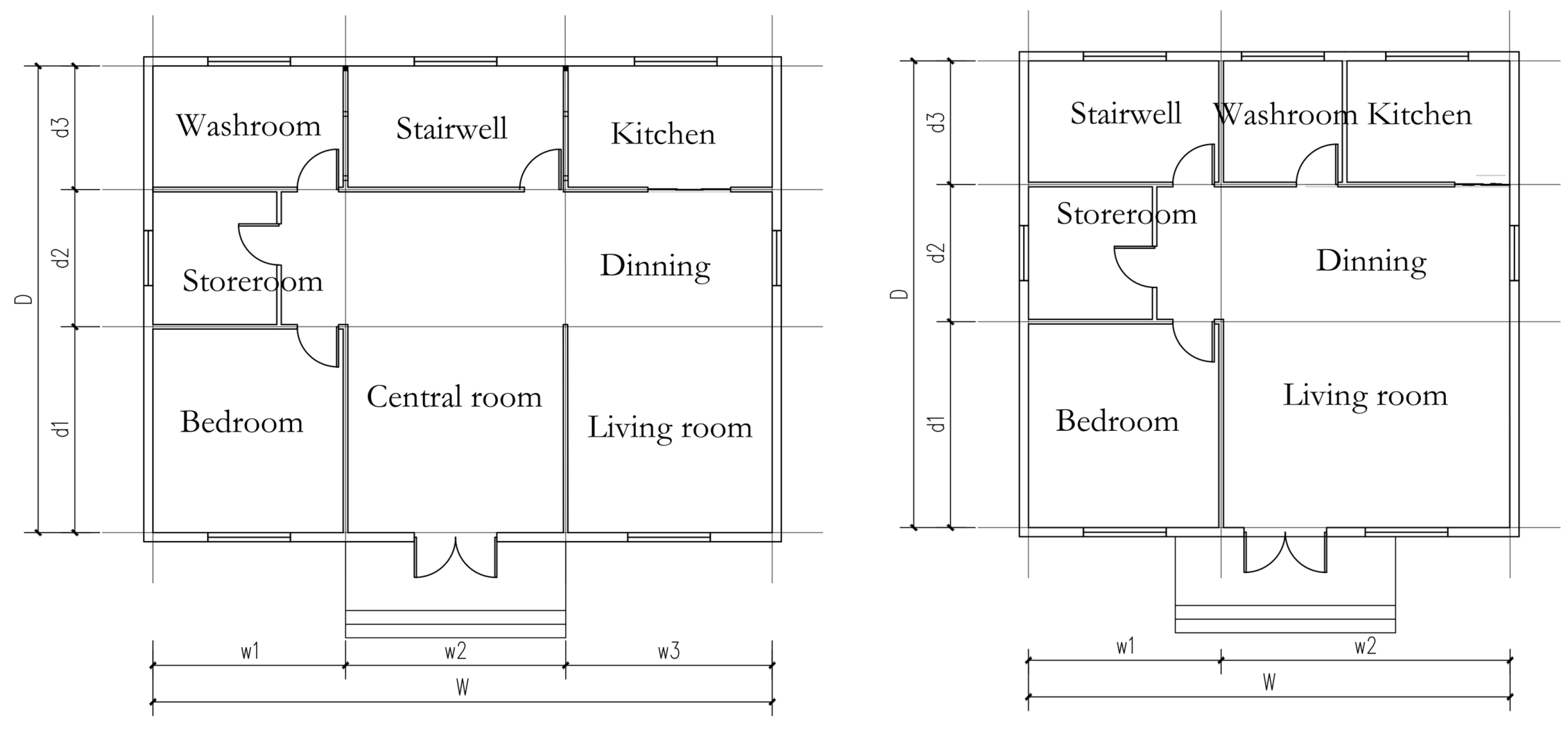
This study concentrates on developing a prototype for rural prefabricated residential layouts, proposing two distinct typologies that serve as the first-generation product portfolio for design matching: a three-bay layout and a two-bay layout (Figure 12). The matching algorithm incorporates preset dimensional thresholds. For the narrowest standardized unit (the two-bay layout), the minimum homestead width is Wmin = 7200 mm, calculated as the sum of the smallest permissible bays (w1 = 3300 mm + w2 = 3900 mm). Homesteads narrower than this threshold necessitate fully customized designs. Conversely, when the homestead width meets or exceeds the maximum threshold of Wmax = 13,500 mm (4200 mm + 4800 mm + 4500 mm), the surplus area can be allocated as a courtyard, or the product dimensions can be correspondingly expanded to accommodate specialized customization needs.
Figure 12.
Schematic plan of two-bay and three-bay layout.
The selection of standardized layouts should first meet the requirements of the regular layout of prefabricated residential buildings, and the layouts should be arranged as compactly as possible. The organization of functional flow lines should save as much usable area as possible, and the efficiency of lighting and ventilation should be good. The bay width should suit conventional interior fit-out and furniture placement, being neither so large as to waste floor area nor so small as to compromise functionality.
To enhance standardization and facilitate the integration of internal functional spaces with prefabricated interior layouts during the axis selection and arrangement process, a minimum modular unit of 300 mm was adopted. Nominal dimensions (e.g., 4000 mm) were adopted for axial bay widths and depths, and the minimum and maximum values of each functional space were predetermined. The compatibility parameters that link specific homestead dimensions to floor plan layouts are defined as follows:
(1) Parametric principle for the three-bay layout
The functional allocation for each bay in the three-bay layout, as illustrated in Figure 12, is defined as follows: width w1 is allocated to the elderly bedroom and northern bathroom; width w2 accommodates the entrance hall and staircase; and width w3 is designated for the dining room and kitchen space. The living room is functionally flexible and can be converted into a bedroom when needed.
The parameter sets for the three-bay layout are defined as follows. The widths w1, w2, and w3 and depths d1, d2, and d3 are constrained to discrete values within their respective ranges:
(2) Parametric principle for the two-bay layout
As illustrated in Figure 12, the bay width w1 corresponds to the elderly bedroom and northern bathroom, whereas w2 encompasses a multifunctional zone containing the main hall, living room, dining room, and staircase. The width w1 and depths d1, d2, and d3 adopt the same discrete value sets and continuous intervals as defined for the three-bay layout, while the width w2, extended for the multifunctional zone, is constrained as follows:
4.2.2. Python-Based Automation for Floor Plan Size and Homestead Size Matching
By inputting the values of width and depth, the Python-based program can automatically match the following combinations of the values and list all results that meet the data filtering rules.
(3) Computational principle for three-bay layouts
The total W and D of the layout are defined as the sums of their respective parametric components (W = w1 + w2 + w3 and D = d1 + d2 + d3). The width and depth components adopt the same discrete value sets and continuous intervals as defined in Section 4.2.1.
(4) Computational principle for two-bay layouts
For this layout, W = w1 + w2 and D = d1 + d2 + d3 under the constraint that w2 > w1. The width and depth components adopt the same discrete value sets and continuous intervals as defined in Section 4.2.1.
(5) Filtering rules and process for calculation results
In the first step of screening, the Cartesian product is utilized. The Cartesian product X × Y of two sets X and Y is the set of all ordered pairs in which the first element belongs to X and the second to Y. In the matching of homestead land, any result of selecting a value from each span of w1, w2, and w3. W can be used as the total set of homestead data and participate in the subsequent screening process. In the second step of screening, the difference among the control surface widths w1, w2, and w3 and the difference among the depth directions d1, d2, and d3 will be used to screen for situations with spans that are relatively close. In the third step, combinations whose total W and D do not exceed the input values are retained, and those closest to the inputs are preferred. In the final filtering step, select cases where the width of the middle span is greater than the span on both sides in order to provide a larger living space. This filtering step can also be set with more flexible data restrictions according to user requirements. With four steps of screening, more suitable homestead data can be selected, reducing the number of available types and lowering the difficulty of user selection.
Formally, the third-step matching is a constrained matching problem. Given the admissible dimension sets S (bay widths) and T (depths), it selects a layout L* and dimensions (w, d) ∈ S × T that satisfy Σwi = W and Σdm = D (or minimize the residual |Σwi − W| + |Σdm − D| when an exact fit is infeasible) and respect the bay-ordering rule w2 > w1 (two-bay)/w2 > max(w1, w3) (three-bay), while preferring the combination with the fewest distinct bay widths so as to reduce candidate variety.
(6) Automated matching calculation for Python-based programs
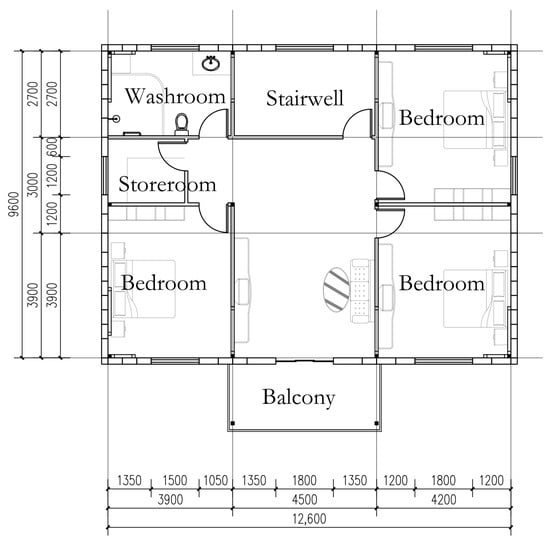
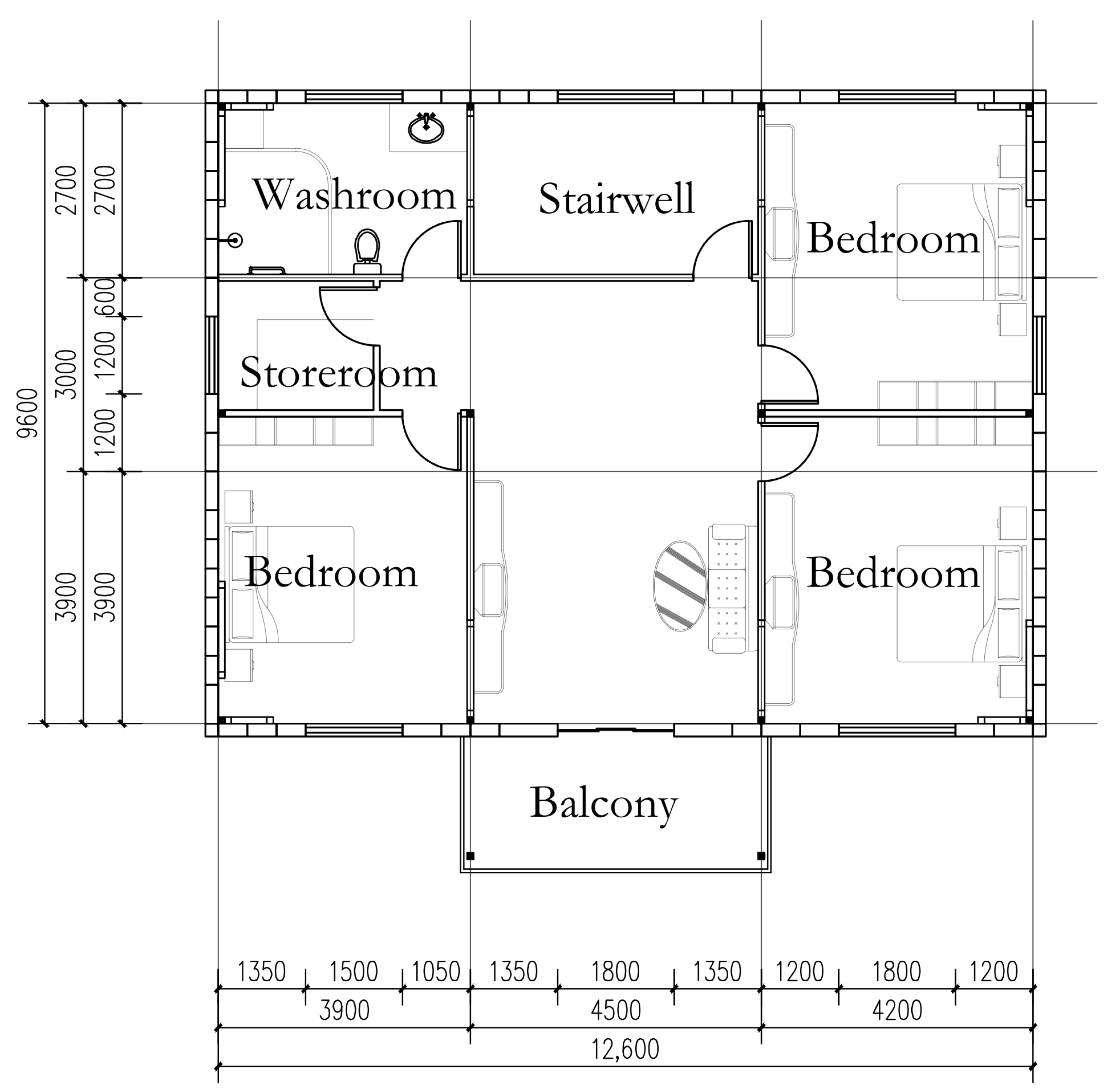
To validate the effectiveness of the Python-based automated matching algorithm developed in this study, a representative homestead scenario with W = 12,600 mm and D = 9600 mm was analyzed. The algorithm successfully identified this configuration as corresponding to a three-bay layout. It then enumerated all feasible combinations of the standardized component parameters (w1, w2, and w3 for width; d1, d2, and d3 for depth) whose sums equate to the input dimensions. All width combinations listed below were filtered to satisfy the bay-ordering rule w2 > max(w1, w3). The computational results summarized in Table 2 demonstrate the algorithm’s capability to generate multiple compliant design solutions from a predefined set of modular components. This output provides a decision-making basis for selecting the most appropriate spatial configuration based on secondary criteria such as functional priorities or cost efficiency.
Table 2.
Feasible component combinations generated for the case (W = 12,600 mm, D = 9600 mm).
The automated matching process is summarized in Algorithm 1 and proceeds as follows:
| Algorithm 1: Automated Homestead–Layout Matching and Component Dimension Selection |
| Input Validation: Read the homestead width W and depth D as inputs, and verify that both fall within the predefined feasible design thresholds. |
| Layout Type Determination: Determine the standardized residential layout prototype (“two-bay” or “three-bay”) from the input total width W. |
| Parameter Enumeration: Enumerate all combinations of component widths wi and depths dj from the standardized dimensional library, subject to Σwi = W and Σdm = D, as formalized in Section 4.2.2. |
| Filtering and Ranking: Filter and rank the feasible combinations using engineering rules, e.g., the bay-ordering constraints w2 > w1 (two-bay) and w2 > max(w1, w3) (three-bay), and discard sub-optimal solutions. |
| Result Output: Output the ranked list of valid component dimension combinations, providing a quantitative basis for component selection and detailed design. |
The above algorithm automatically generates the dimensions of each axis opening and matches them based on the standardized residential products provided above. Combined with the specific parameters input by the user in the front-end web, such as the number of floors, required rooms, balconies/terraces, etc., the product layout that matches the user’s homestead can be obtained. Assuming the user input conditions for this floor plan matching design are a three-bay layout with two floors, we have selected the following set of values:
The following is a schematic diagram of the first and second floor plans formed after generating data (Figure 13), with a structural layout using lightweight steel structures as an example.
Figure 13.
Automatically generated standardized product layout for the residential product.
4.3. Selection and Optimization of Standardized Structural Component Systems
The selection and standardized optimization design of structural components for rural prefabricated housing are important components for realizing the rural prefabricated product platform. This paper studies the design principles and construction methods of the three structural component systems mentioned above and conducts component selection and design based on the key technical characteristics of their structural component systems. The use of structural components for standardized and selective design is determined based on the spatial layout of the house generated with the dimensions of the homestead mentioned above.
The use of standardized structural component systems with standardized selection can improve the efficiency of structural layout. Due to the differences in the three rural prefabricated housing systems, the logic and methods of their structural layout also differ. Among them, the prefabricated composite cavity structural component system is a building system that integrates structure and enclosure, and its structural layout is almost identical to the enclosure and partition component system that divides room functions. The prefabricated lightweight steel structure system adopts a combination of frame structural components and square steel columns, and its layout needs to consider the efficiency of structural arrangement to reduce steel consumption. The structural layout of prefabricated rigid skeleton system is the most versatile and flexible. Due to the relatively large size of its structural components, the internal separation can also be flexible and variable.
4.3.1. Selection and Optimization of Standardized Structural Columns and Beams
The layout of the structure is first estimated by the designer based on the type of structural system. Generally speaking, a two-bay column grid structure is sufficient for a three-bay rural residential building. At the same time as arranging the structure, fixed space modules and variable space modules need to be determined. However, the structure of the prefabricated composite cavity is designed as an integrated unit with the internal partition, so it is not within the scope of research on spatial variability.
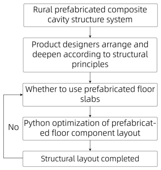
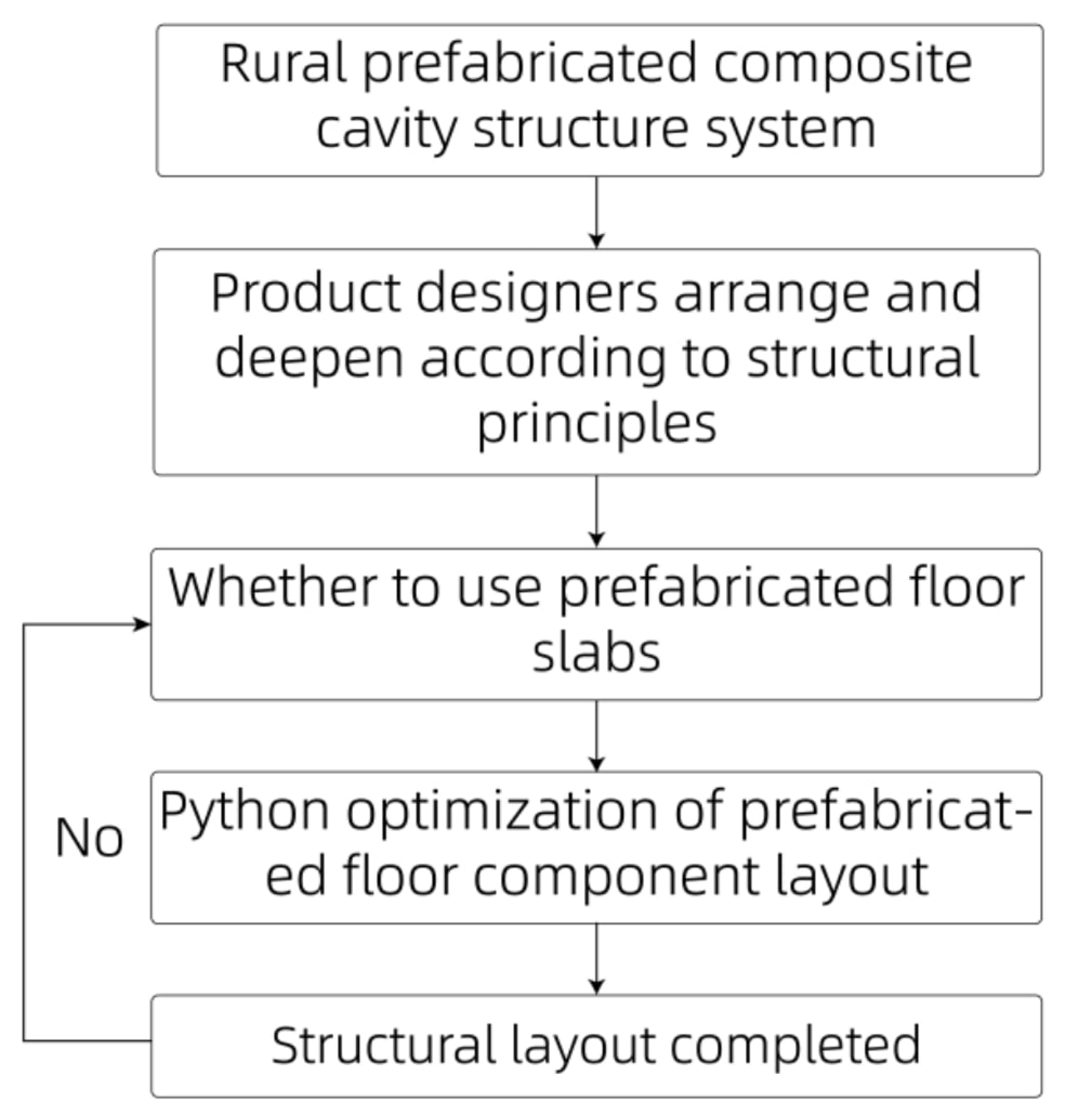
(1) Matching of the rural prefabricated composite cavity structure
The structural matching process of the rural prefabricated composite cavity is shown below (Figure 14). When determining its layout, the structure can be arranged according to a standardized component system. When using prefabricated floor slabs, the following floor layout optimization process can be followed.
Figure 14.
Layout process diagram of the rural prefabricated composite cavity structure.
The composite cavity structure layout generated according to the above dimensions of the homestead is shown in Figure 14.
(2) Structural matching of the rural prefabricated lightweight steel structure
The matching and optimization design process of rural light steel structure is shown in Figure 15 because the layout principle of its prefabricated structural system is to use the frame members with smaller sections.
Figure 15.
Structural layout of the rural prefabricated composite cavity.
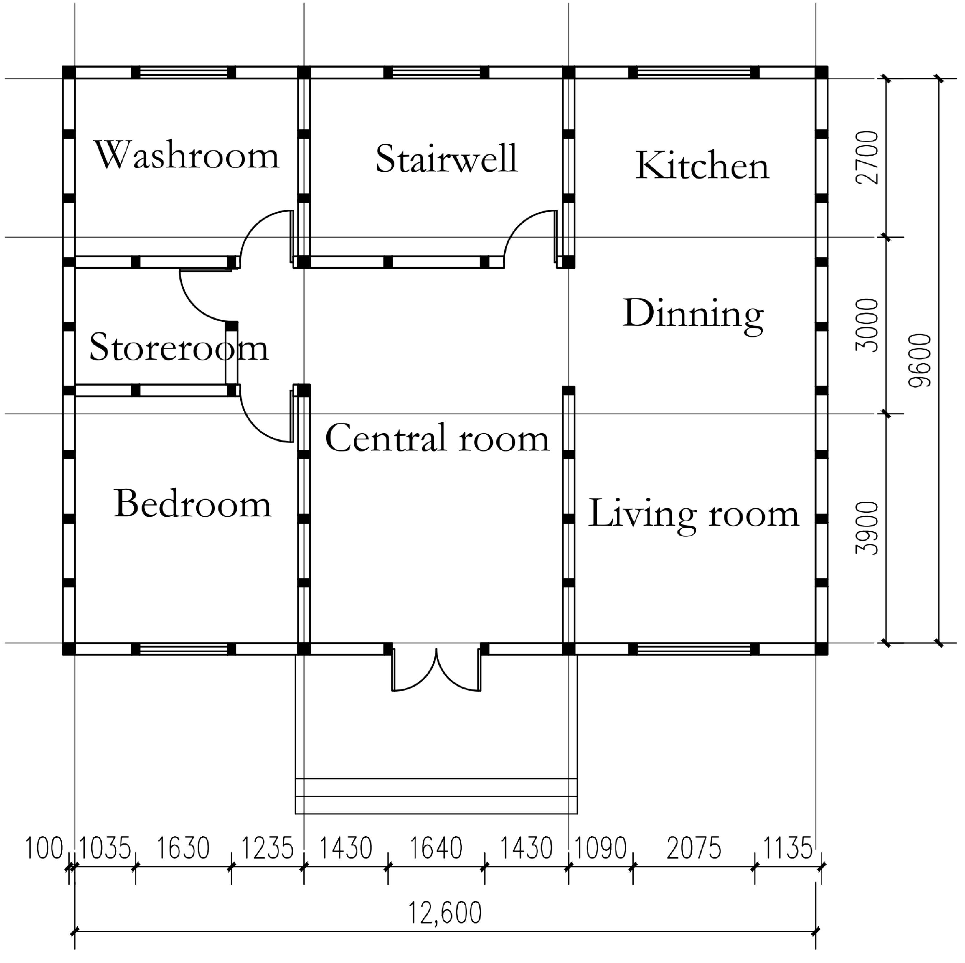
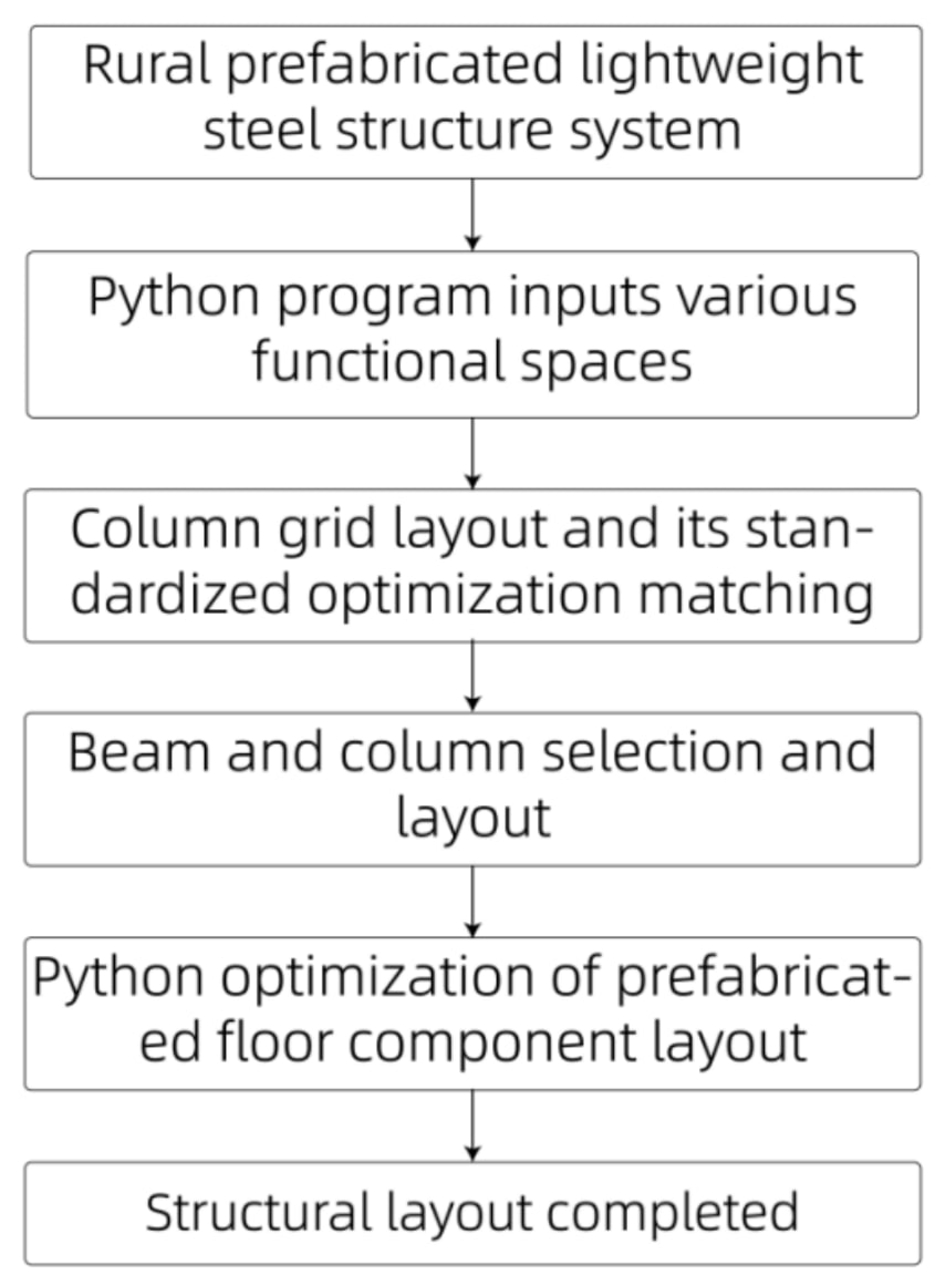
The flow chart of the lightweight steel structural layout and the resulting structural layout are shown in Figure 16 and Figure 17, respectively.
Figure 16.
Layout flow chart of rural prefabricated lightweight steel structure.
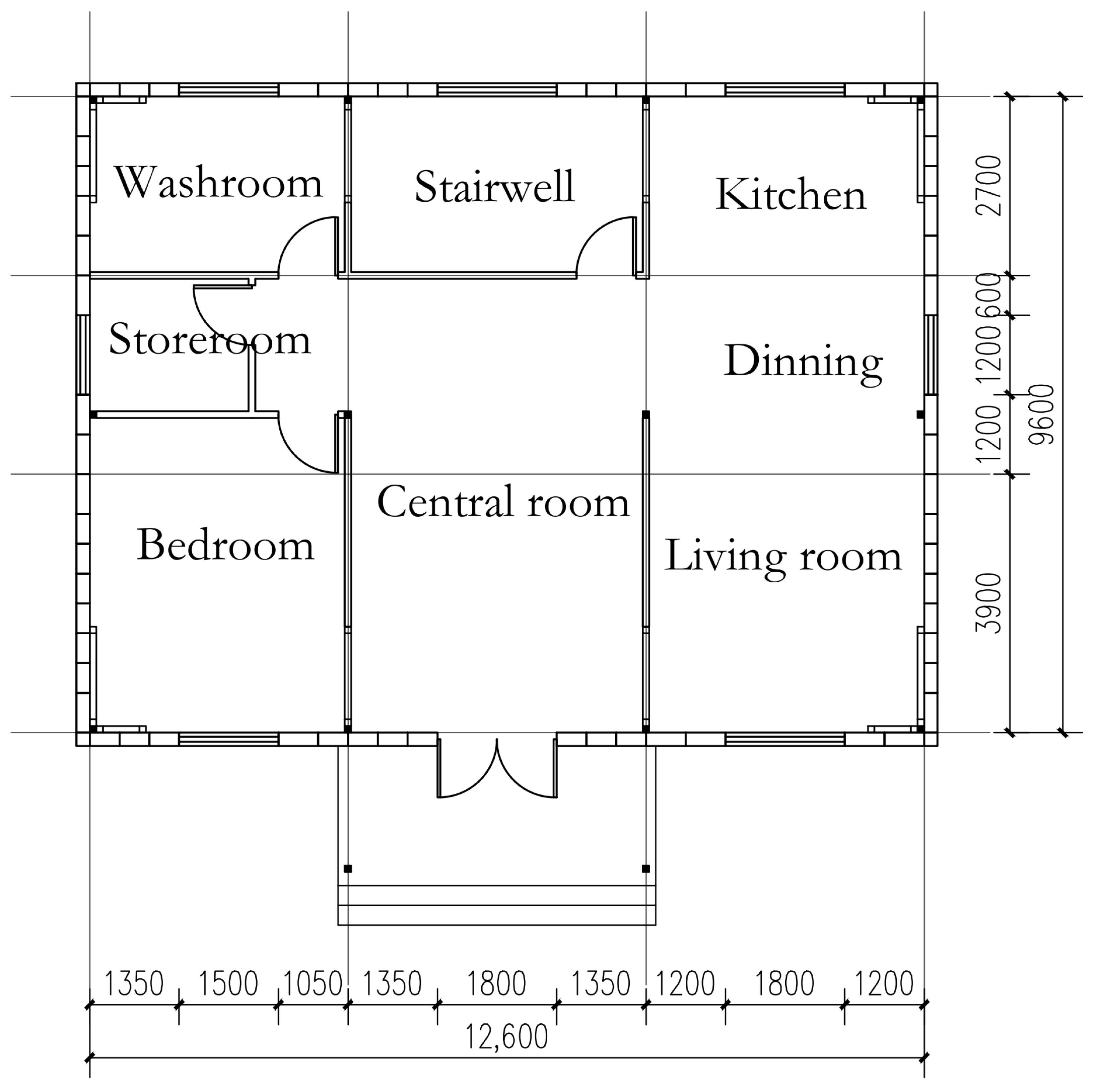
The layout of light steel structure according to the above generated size of homestead is as follows:
Figure 17.
Layout of the rural prefabricated lightweight steel structure.
Once the homestead dimensions are confirmed, the user enters the three-bay house type and selects the lightweight steel system in the structural layout program, which then matches the structural configuration to the previously generated plan and outputs the quantities of basic members (columns, beams, and floor slabs). The resulting list of structural members is given in Table 3.
| Structural Layout Generation Procedure (LSSCS) |
| System Initialization: Launch the program and load the predefined databases for structural systems (LSSCS, RSCS, CCCS) and member libraries. User Interaction and Input: Prompt the user to select a structural system from the available options and then select a bay layout (two-bay or three-bay). Core Calculation: Based on the selected system and layout, retrieve the corresponding parametric rules and spatial dimension sets. The number and standard size of columns, the types, quantities, and lengths of beams required for the frame, and the number and dimensions of floor slabs needed to cover the plan can be calculated automatically. Result Compilation and Output: Format and display the complete list of structural members with their specifications. |
Table 3.
Automatically generated structural member list for the two-story, three-bay light steel structure case.
(3) Rigid skeleton system structure matching
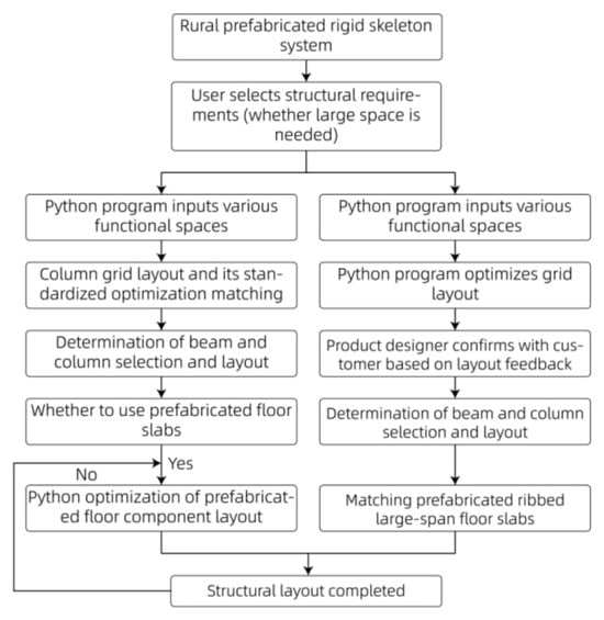
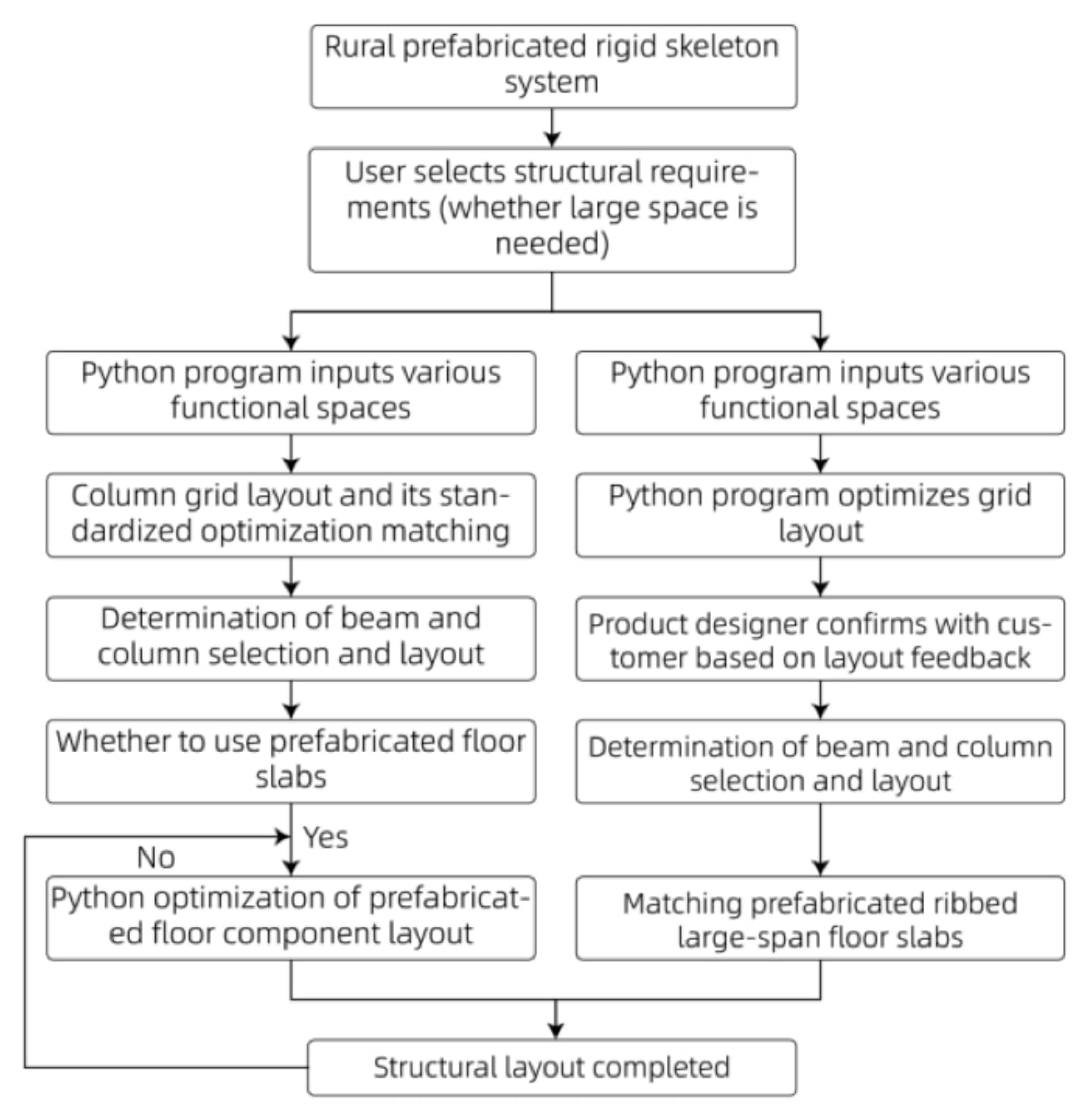
The prefabricated rural RSCS can meet the needs of users for large indoor space. When selecting and arranging the structure, it can be selected according to the needs of users. The process is shown in Figure 18.
Figure 18.
Flowchart for structural layout optimization of the rural prefabricated rigid framework system.
The standardization of a residential layout structure system requires that structural elements do not compromise functional integrity. To achieve this, structural components, particularly columns, must be positioned at the corners of the building’s enclosure, thereby maximizing the continuity and utility of the interior space. The rigid frame structure system offers significant flexibility, accommodating both conventional small-span and large-span layouts. This adaptability allows for the customization of column placement based on structural feasibility and user requirements, generating diverse structural solutions. A key principle for standardized production is to minimize the variety of column cross-sectional sizes. As illustrated in the accompanying figures, a standard three-bay layout can adopt a conventional structural scheme (RSCS-R), with columns positioned at axis intersections. Conversely, for users prioritizing expansive, unobstructed interiors, a large-space scheme (RSCS-L) can be implemented. This scheme reduces the number of columns within the main living area, instead utilizing larger-sized columns at the four corners of the large space. Figure 19 depicts the conventional three-span rigid frame layout. The corresponding automatically generated structural member list is given in Table 4.
Figure 19.
Schematic diagram of RSCS-R.
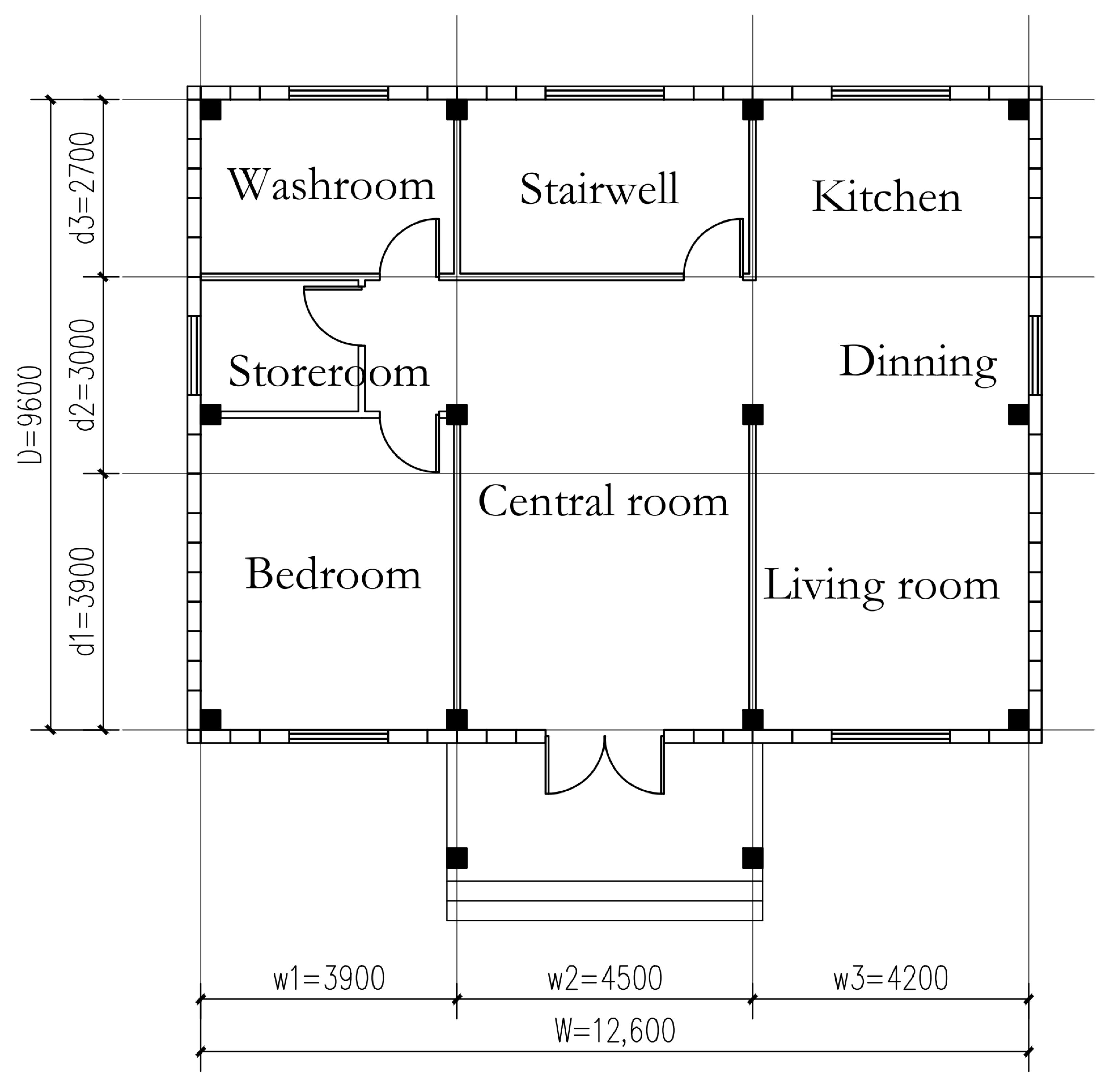
Table 4.
Automatically generated structural member list for the two-story, three-bay RSCS-R.
After automatic calculation using Python-based program, the layout of the two-story three-bay RSCS-R residential product needs to arrange a total of 14 square reinforced concrete columns, 34 rectangular reinforced concrete beams, and five types of concrete beams. Table 5 lists the detailed parameters and types of the beams, slabs, and columns involved in this study. The floor size in this step is the size of the whole floor without division. The specific partition and refinement value of this size will be further optimized in the floor matching program below. See Figure 20.
Figure 20.
Schematic diagram of RSCS-L.
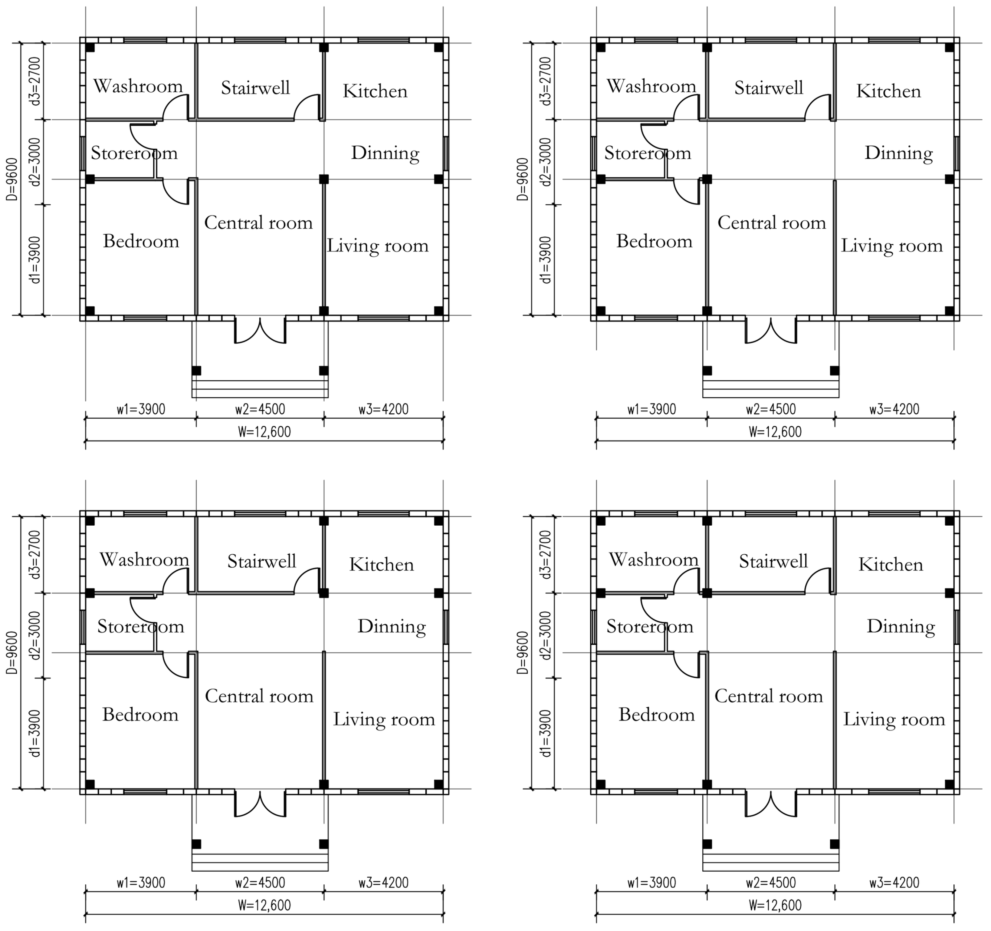
Table 5.
Automatically generated structural member list for the two-story, three-bay RSCS-L.
When the user chooses to have large space requirements, after automatic calculation using Python-based program, the layout of three-bay, two-story RSCS-L needs to arrange a total of 11 square reinforced concrete columns, with two types of sizes (type 1 of 400 mm × 400 mm, type 2 of 600 mm × 600 mm), a total of 30 rectangular reinforced concrete beams, and a total of five types of concrete beams. The floor size in this step is the size of the whole floor without division. The specific partition and refinement value of this size will be further optimized in the floor matching program below. According to the data matching results of the above Python-based program, combined with the four conventional structural arrangements shown in Figure 21, the structural arrangement type B-2 not only meets the needs of large space but also realizes the flexible organization and use of internal space.
Figure 21.
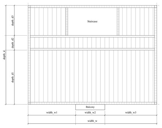
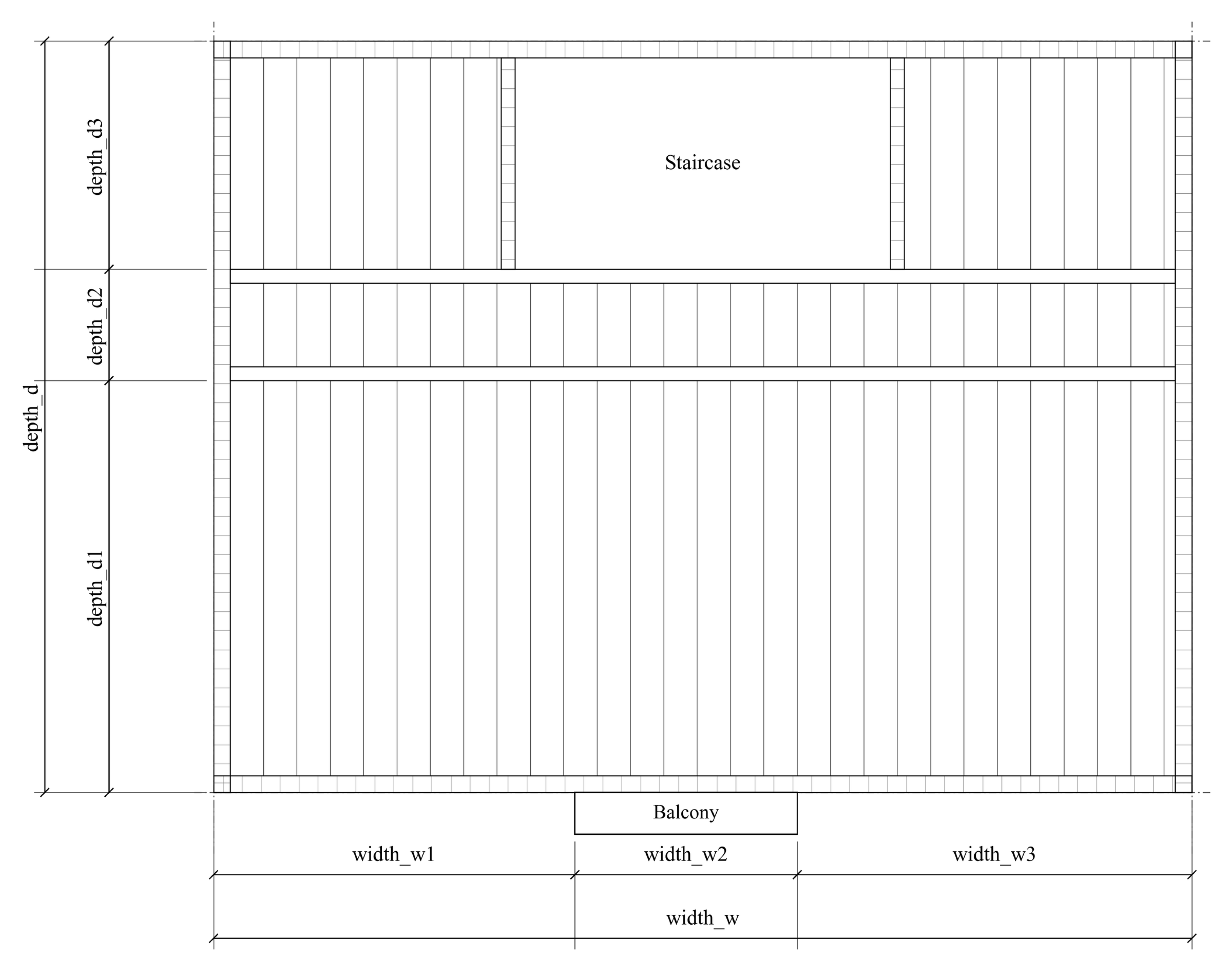
Layout of standardized prefabricated floor slab.
4.3.2. Standardized Prefabricated Floor Layout and Optimization
After determining the column grid layout and the specific size information of the whole floor, the prefabricated floor can be arranged and optimized. When the ALC autoclaved lightweight concrete standard size plate (the conventional standard component size is 600 mm × 600 mm) is used, it can be arranged directly according to the size of the structural space (Figure 21). This is taken as an example to optimize the prefabricated floor.
When non-standard slab or precast concrete floor systems are employed, a Python-based computational assistant is utilized for auxiliary design calculations. Based on the structural layout information generated for the aforementioned two-story, three-bay light steel structure, the analysis indicates a requirement for seven distinct floor panels. Their specifications are as follows: type 1, 3750 mm × 4650 mm (1 panel); type 2, 4400 mm × 4650 mm (1 panel); type 3, 4050 mm × 4650 mm (1 panel); type 4, 3750 mm × 4650 mm (1 panel); type 5, 4400 mm × 2200 mm (1 panel); type 6, 4050 mm × 4650 mm (1 panel); and type 7, 4400 mm × 1900 mm (1 panel).
The corresponding set of required floor widths is derived as follows:
For walls requiring non-standard panel lengths, panels are selected and combined from a predefined set of standard width modules as follows:
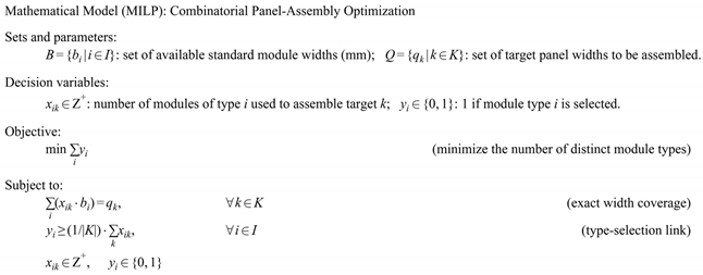
Thus, the assembly of large floor panels is formalized as a combinatorial optimization problem. For each unique target width in set Qa, all feasible combinations of elements from set B whose summed width equals the target must be identified. A dedicated Python program was developed to solve this problem, with the following analytical objectives: (1) to determine the minimum number of distinct element types from B required to satisfy all targets; (2) to quantify the differences between alternative feasible combinations for a given target; and (3) to enumerate all satisfactory combinations exhaustively.
To make the optimization explicit, the panel assembly task is stated as the following mixed-integer linear program (MILP) that minimizes component-type diversity:
| Mathematical Model (MILP): Combinatorial Panel-Assembly Optimization |
| Sets and parameters: B = {bi|i ∈ I}: set of available standard module widths (mm); Q = {qk|k ∈ K}: set of target panel widths to be assembled. Decision variables: xik ∈ Z+: number of modules of type i used to assemble target k; yi ∈ {0,1}: 1 if module type i is selected. Objective: min Σi yi (minimize the number of distinct module types) Subject to: Σi (xik · bi) = qk, ∀ k ∈ K (exact width coverage) yi ≥ (1/|K|) · Σk xik, ∀ i ∈ I (type-selection link) xik ∈ Z+, yi ∈ {0,1} |
The same formulation applies to the exterior wall panel optimization (Section 4.3.3) by substituting B with the wall module set and Q with the wall segment widths; the corresponding exterior-wall case realizes the minimum-type solution {600, 450} mm. Figure 24.
In order to improve the computational efficiency, the set Qb is simplified by removing the repetition width, and the simplified set is obtained as follows:
This step significantly reduces the complexity of the problem because panels that share the same width can be partitioned using the same combination mode. The complete procedure is summarized in Algorithm 2.
Combinatorial Optimization for Floor Panel Assembly
| Algorithm 2: Combinatorial Optimization of Standardized Floor-Panel Components |
| Input/Problem Definition: Given the target width set Qb and the standard module width set B, find for every target width qk ∈ Qb a combination of modules from B satisfying Σi (xik · bi) = qk, while minimizing the number of distinct module types (min Σi yi), per the MILP model in Section 4.3.2. |
| Data Preprocessing: Remove duplicate elements from the initial set Qa to obtain the unique set Qb, reducing the number of combinatorial enumerations. |
| Combination Generation and Feasibility Check: For each target width qk∈ Qb, enumerate module combinations from B and retain those satisfying Σi (xik · bi) = qk as feasible; the binary variables yi indicate the module types employed. |
| Result Analysis and Output: Aggregate all feasible schemes for the target widths in Qb, and output the number of valid combinations and each specific scheme (module widths and quantities), as shown in Table 6. |
Table 6.
Calculation results of Python program automatic operation.
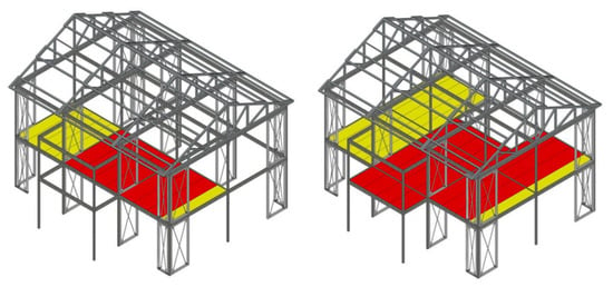
From the results obtained, it can be seen that at least two different widths of floor slabs are required to match all the floor slabs. Therefore, panels of 750 mm and 1100 mm widths are adopted, with quantities of six and seven, respectively.
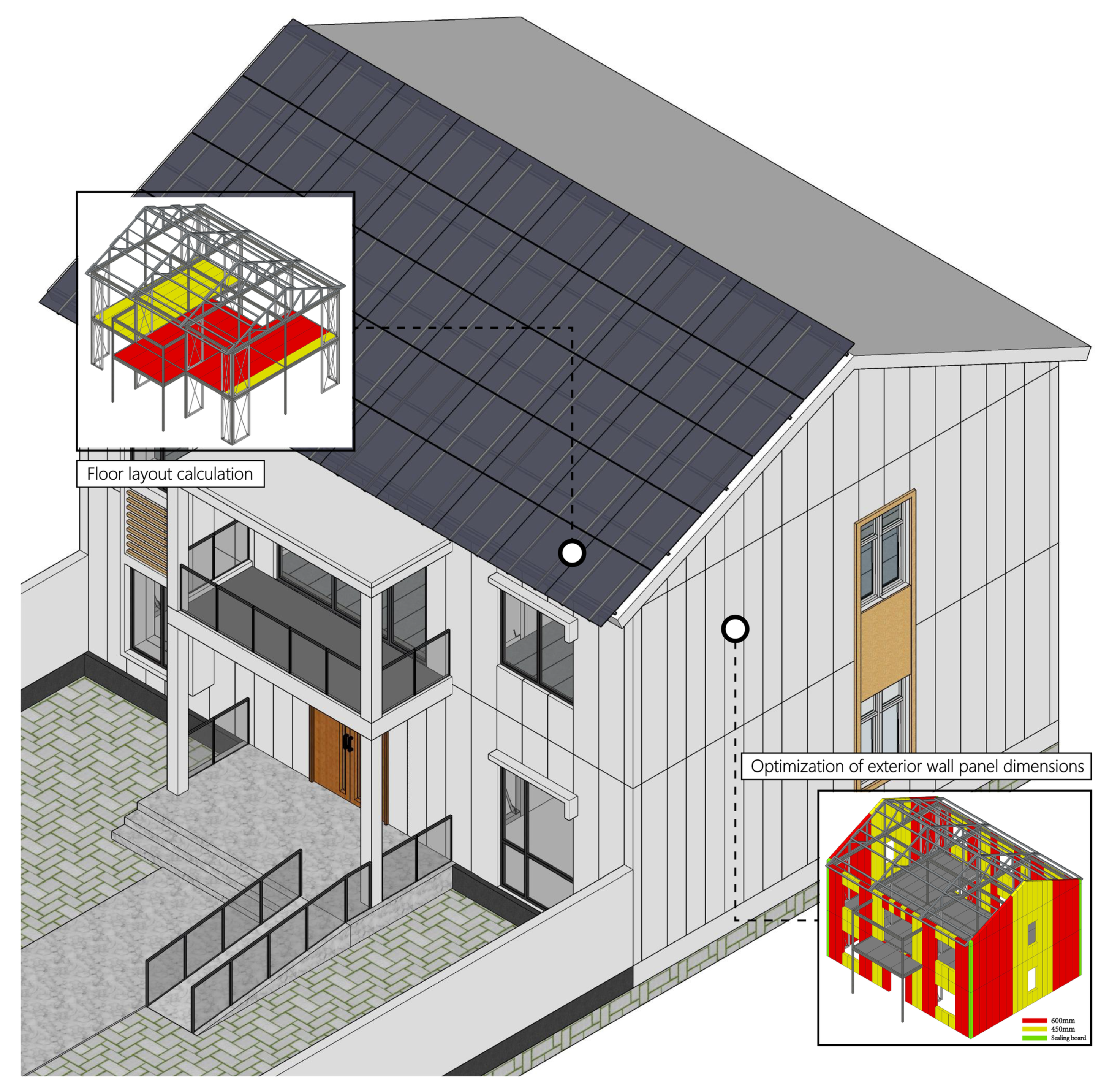
The width of the red floor is 1100 mm, a total of seven are used, and the width of the yellow floor is 750 mm, a total of six are used, which is in line with the results of the program calculation. Panels of equal width are partitioned in the same manner, yielding the complete floor layout shown in Figure 22. The standardized prefabricated floor layout is thus obtained with Python-assisted calculation.
Figure 22.
Floor layout standardization optimization effect for display 2.
4.3.3. Standardization and Optimization of Prefabricated Peripheral Wall Panel System
(1) Parametric design principles for prefabricated exterior wall systems
The exterior enclosure wall system constitutes a critical component of rural prefabricated residences, typically accounting for a significant portion of the total building materials in terms of both quantity and surface area. Generally, the prefabricated exterior wall panels are designed and spliced by the existing standardized products in the market. Because there are many types of boards, the common prefabricated exterior wall boards include ALC exterior wall board standardized size components, wood structure composite exterior wall board types, and precast concrete board exterior wall boards. Some of the dimensions of the exterior wall panels are designed and divided according to the needs of the project to meet the use needs of the project. This section presents an automated workflow for the standardization optimization of the exterior wall panel system during product customization. It can be applied to various scenarios. The layout scope and number of exterior wall panels are shown in Figure 23.
Figure 23.
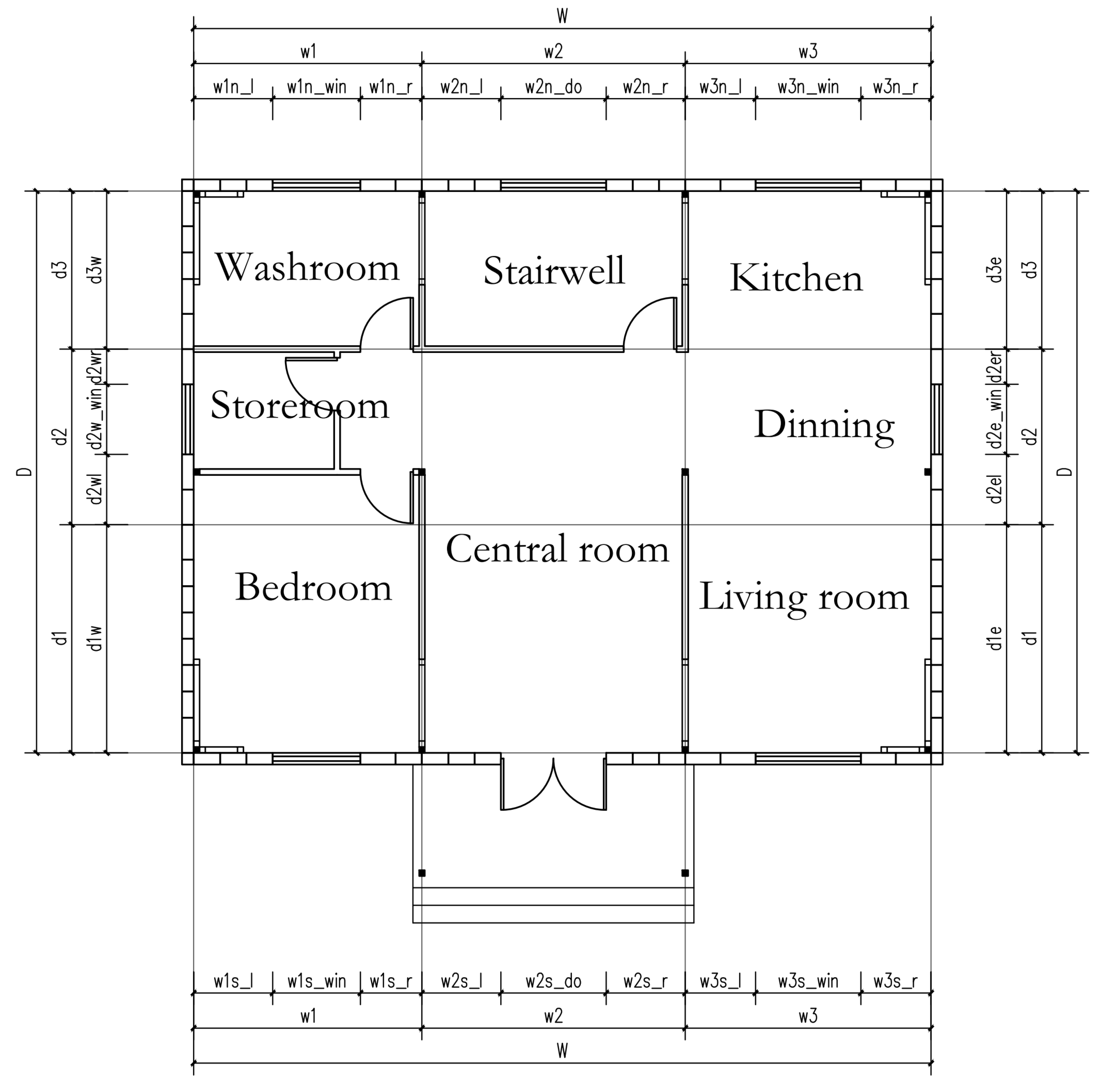
Layout scope and area number of exterior wall panels.
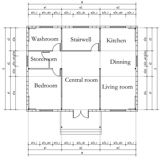
The four elevations of the standardized house types are designated South (S), North (N), East (E), and West (W) according to their cardinal orientation. Here, w1s_win is the width of the window of the first span on the left, w1s_l is the layout range of the outer wall panel on the left side of the window of the first span column grid space, and w1s_r is the layout range on the right side of the window. By analogy, the number corresponding to the area within the layout range of other exterior wall panels can be obtained.
Among them, in order to achieve the goal of standardized design, the doors and windows of the house type product are preset standardized size values. The width of the window is determined based on the span of its room to meet the efficiency of lighting and ventilation. Specific parameterization requirements are as follows:
The preset value of the thickness of the inner and outer walls is taken as 200 mm. t_wall = 200 mm.
(2) Python-based automatic optimization
This optimization is based on Python to optimize a series of functions in order to find the standardized optimal solution for the prefabricated exterior wall panel. The optimization process is first based on the design mode of finalization and selection of prefabricated exterior wall panels. A panel size series suitable for rural areas in the southern Jiangsu region is then selected. The preset height of the prefabricated exterior wall panel is consistent with the floor height. The floor height of the first and second floors of this standardized rural residential product is 3600 mm, so the width of the standardized exterior wall panel is generally not less than 1/10 of the height and not more than 1/3 of the height. In addition, the number of changes in the width of the board is limited, and its minimum modulus is 50 mm. The relevant sets are defined as follows:
Taking the above plan as an example, the Python program enumerates all wall panel lengths as Qa. Removing duplicate lengths yields the reduced set Qb, and combining the two sets gives the combined candidate set Qc used for non-standard configurations.
Formulating the same combinatorial optimization problem over these sets and running the Python program yields the results shown in Table 7.
Table 7.
Calculation results of the Python-based program automatic operation.
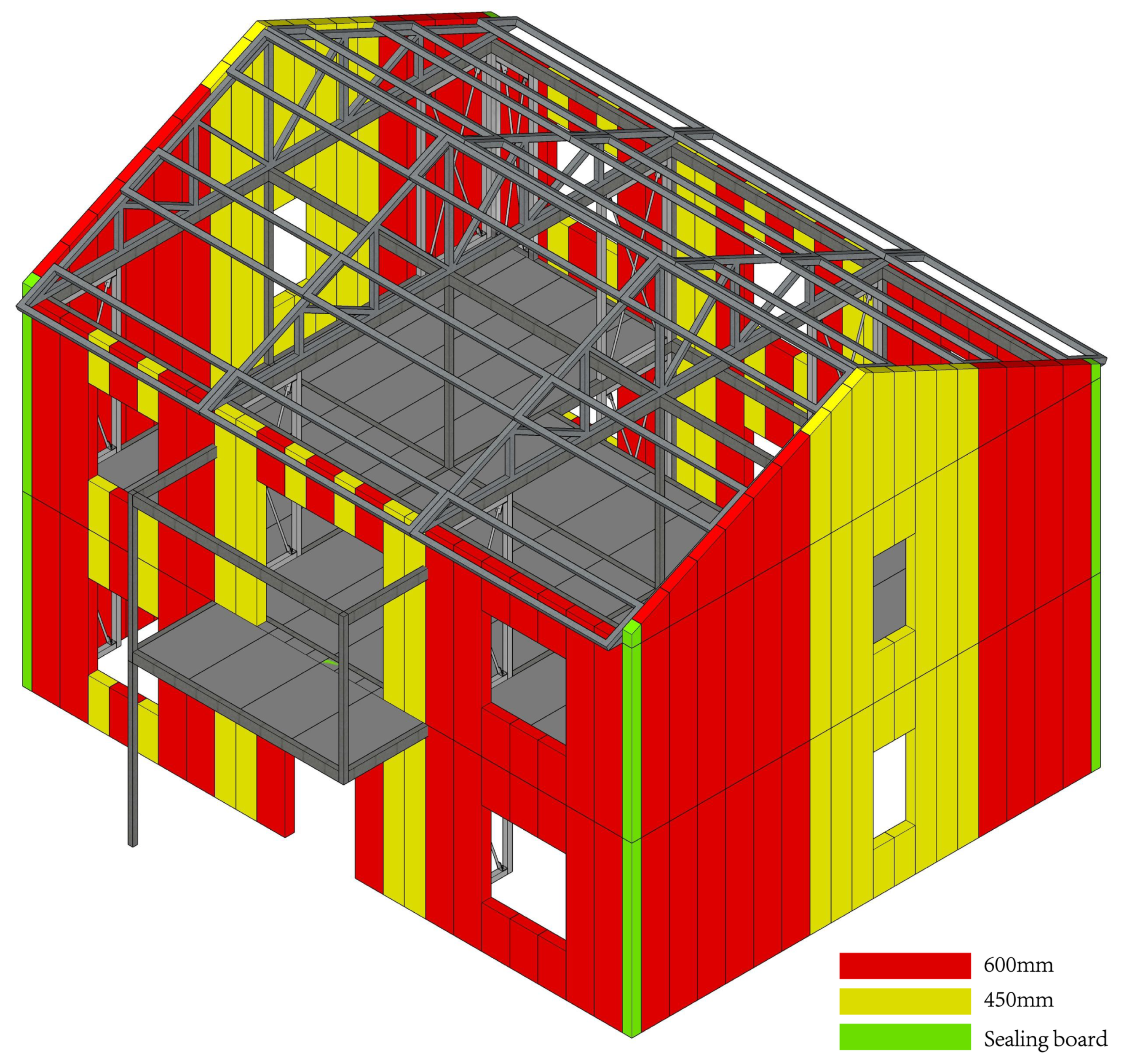
In the above case, the computer generated four kinds of calculation results. The width of the wall panel used is {450, 300}, {300, 350}, {300, 550}, and {600, 450}, respectively, and these results meet the requirements of the wall panel layout. Among these options, the combination of 600 mm and 450 mm panels—the two largest widths—was selected, as it minimizes the total number of wall panels (Figure 24).
This selection corresponds to the feasible solution of the MILP in Section 4.3.2 with the smallest |I|, i.e., the fewest distinct panel types.
Figure 24.
Schematic diagram of effect after optimized layout of exterior wall panels.
(3) Export of component system list of standardized assembled residential products
Using standardized homestead matching, structural component selection, structural information generation, and floor and wall panel optimization, the required house plan is obtained (Figure 25). On this basis, designers can deepen the plane furniture layout and establish a complete three-bay, two-story LSSCS prefabricated rural residential product standardization model (Figure 26), so as to realize the product matching design and standardized optimization process of rural assembly housing in southern Jiangsu based on Python.
Figure 25.
Plan of the second floor of three-bay, two-story RLPR of LSSCS.
Figure 26.
Standardized model of the three-bay, two-story LSSCS RLPR.
After completing the above process, the standardization and optimization of the structural and exterior envelope component systems are essentially complete.
5. Discussion
This paper is limited to three types of RLPR for standardized component system research, which cannot fully cover the new types of prefabricated building systems in rural areas of the southern Jiangsu region. Due to the fact that the three selected systems are all familiar and practiced prefabricated building systems, the framework inherently embeds certain assumptions. Moreover, emerging low-carbon structural systems, such as timber and bamboo, remain underrepresented in the southern Jiangsu context. At the same time, research on the construction and design of prefabricated residential buildings based on component systems requires a detailed and in-depth understanding of the specific standardized design methods, key construction technologies, and final implementation effects of each prefabricated system. This study therefore focuses on prefabricated systems with which the team has substantial practical experience; extending the framework to other systems will require further design research and construction practice.
This paper is based on the research of component system types for RLPR, aiming to improve the standardization level of rural prefabricated housing. Quantitative performance gains from the improved standardization level—notably cost and carbon-emission comparisons—have not yet been evaluated. A natural next step is therefore to assess the benefits and potential trade-offs introduced by higher component standardization.
6. Conclusions
This study addresses the development needs of rural prefabricated housing, focusing on the standardized design of typical dwellings in southern Jiangsu. Grounded in component system standardization theory, it develops a graded standardization strategy and a quantitative control method for RLPR component systems, thereby providing a quantitative basis for standardized rural residential design in this region.
Three prefabricated residential building systems suited to southern Jiangsu were developed and validated: the rural prefabricated lightweight steel system, the rural prefabricated concrete rigid skeleton system, and the ruralcomposite cavity components system. Guided by the Python programs described above, product-matching design and component system standardization optimization were implemented for prefabricated rural housing.
Author Contributions
Conceptualization, W.L.; methodology, W.L. and Q.W.; software, X.D.; validation, C.W.; formal analysis, Y.W.; investigation, H.Y.; resources, X.D.; data curation, Y.L.; writing—original draft preparation, Y.L.; writing—review and editing, W.L.; visualization, Y.L.; supervision, Q.W.; project administration, C.W.; funding acquisition, W.L. All authors have read and agreed to the published version of the manuscript.
Funding
This research is funded by Jiangsu University of Science and Technology, grant number 1122932405.
Informed Consent Statement
Not applicable.
Data Availability Statement
The Python source code implementing the homestead–layout matching, structural component selection, and floor/exterior–wall panel combinatorial optimization algorithms described in this paper, together with the standardized dimensional parameter library, is available from the corresponding author upon reasonable request. The household survey datasets generated during the study are not publicly available due to privacy restrictions but can be requested from the authors.
Conflicts of Interest
Author Yihan Lv was employed by the company China State Construction Engineering Corporation Co., Ltd. Author Yanhua Wu was employed by the company Architects & Engineers Co., Ltd. of Southeast University Author Congjun Wang was employed by the company Zhongyifeng Construction Group Co., Ltd. The remaining authors declare that the research was conducted in the absence of any commercial or financial relationships that could be construed as a potential conflict of interest.
Abbreviations
| RLPR | Rural Low-Rise Prefabricated Residence |
| LSSCS | Prefabricated Lightweight Steel Structural Component System |
| RSCS | Rigid Skeleton Component System |
| CCCS | Composite Cavity Component System |
| MILP | Mixed-Integer Linear Program |
| ALC | Autoclaved Lightweight Concrete |
| DfMA | Design for Manufacture and Assembly |
References
- Stenbacka, S.; Cassel, S.H. Planning for socially sustainable rural housing in Sweden. J. Rural Stud. 2024, 110, 103377. [Google Scholar] [CrossRef] [Scilit]
- Liu, Y.S. Introduction to land use and rural sustainability in China. Land Use Policy 2018, 74, 1–4. [Google Scholar] [CrossRef] [Scilit]
- Geng, Y.; Yang, X.; Zhang, N.; Li, J.; Yan, Y. Sustainable rural development: Differentiated paths to achieve rural revitalization with case of Western China. Sci. Rep. 2024, 14, 1–25. [Google Scholar] [CrossRef] [Scilit]
- Hossain, M.; Park, S.; Shahid, S. Frugal innovation for sustainable rural development. Technol. Forecast. Soc. Change 2023, 193, 122662. [Google Scholar] [CrossRef] [Scilit]
- National Bureau of Statistics of China. China Statistical Yearbook; China Statistics Press: Beijing, China, 2023.
- Djukanovic, M.; Alegre, A.; Teixeira Bastos, F. Prefabricated Solutions for Housing: Modular Architecture and Flexible Living Spaces. Buildings 2025, 15, 862. [Google Scholar] [CrossRef] [Scilit]
- Huang, Q.; Wang, J.; Ye, M.; Zhao, S.; Si, X. A Study on the Incentive Policy of China’s Prefabricated Residential Buildings Based on Evolutionary Game Theory. Sustainability 2022, 14, 1926. [Google Scholar] [CrossRef] [Scilit]
- Luo, X.; Zheng, X.; Liao, C.; Xiao, Y.; Deng, C.; Liu, S.; Chen, Q. Research on the Modular Design Method and Application of Prefabricated Residential Buildings. Buildings 2024, 14, 3014. [Google Scholar] [CrossRef] [Scilit]
- Yuan, Z.; Man, Q.; Guan, Z.; Yi, C.; Zheng, M.; Chang, Y.; Li, H.X. Simulation and optimization of prefabricated building construction considering multiple objectives and uncertain factors. J. Build. Eng. 2024, 86, 108830. [Google Scholar] [CrossRef] [Scilit]
- Wang, Q.; Guo, W.; Xu, X.; Deng, R.; Ding, X.; Chen, T. Analysis of Carbon Emission Reduction Paths for the Production of Prefabricated Building Components Based on Evolutionary Game Theory. Buildings 2023, 13, 1557. [Google Scholar] [CrossRef] [Scilit]
- Yang, B.; Jiang, S.; Dong, M.; Zhu, D.; Han, Y. Graph Database and Matrix-Based Intelligent Generation of the Assembly Sequence of Prefabricated Building Components. Appl. Sci. 2023, 13, 9834. [Google Scholar] [CrossRef] [Scilit]
- Zheng, W.; Feng, R.; Wang, Y.; Shao, T.; Chow, D.; Zhang, L. Fundamental Research on Sustainable Building Design for the Rural Elderly: A Field Study of Various Subjective Responses to Thermal Environments and Comfort Demands during Summer in Xi’an, China. Sustainability 2024, 16, 7778. [Google Scholar] [CrossRef] [Scilit]
- Wang, M.; Xu, Y.; Shen, R.; Wu, Y. Performance-Oriented Parametric Optimization Design for Energy Efficiency of Rural Residential Buildings: A Case Study from China’s Hot Summer and Cold Winter Zone. Sustainability 2024, 16, 8330. [Google Scholar] [CrossRef] [Scilit]
- Zou, D.; Sun, C.; Gao, D. Multi-Objective Optimization-Driven Research on Rural Residential Building Design in Inner Mongolia Region. Energies 2025, 18, 1867. [Google Scholar] [CrossRef] [Scilit]
- Wang, Z.; Wang, C.; Dou, H.; Cheng, G.; Zhang, J.; Lei, X.; Huang, X. A strategy of building a beautiful and harmonious countryside: Reuse of idle rural residential land based on symbiosis theory. Habitat Int. 2025, 155, 103238. [Google Scholar] [CrossRef] [Scilit]
- GB/T 50002-2013; Code for Modular Coordination in Building. Ministry of Housing and Urban-Rural Development of the People’s Republic of China: Beijing, China, 2013.

Disclaimer/Publisher’s Note: The statements, opinions and data contained in all publications are solely those of the individual author(s) and contributor(s) and not of MDPI and/or the editor(s). MDPI and/or the editor(s) disclaim responsibility for any injury to people or property resulting from any ideas, methods, instructions or products referred to in the content. |
© 2026 by the authors. Licensee MDPI, Basel, Switzerland. This article is an open access article distributed under the terms and conditions of the Creative Commons Attribution (CC BY) license.