


Abstract
Alkali-activated slag (AAS) is a promising low-carbon alternative to ordinary Portland cement owing to its low CO2 emissions and excellent mechanical performance. However, its rapid structural build-up, fast loss of flowability, and short setting time restrict its application in grouting engineering. In this study, slag was subjected to controlled carbonation pretreatment to regulate its physicochemical properties, and the effects of carbonated slag (CS) on the fresh and hardened properties of AAS grouting materials were systematically investigated. The physicochemical characteristics of CS were analyzed by X-ray diffraction (XRD), Fourier transform infrared spectroscopy (FTIR), thermogravimetric analysis (TGA), and scanning electron microscopy (SEM), while rheological behavior, setting time, compressive strength, grouting performance, and hydration products were further evaluated using NaOH- and waterglass-activated systems. The results showed increased carbonate formation and discrete Ca-rich deposits on the examined slag surfaces, while no major change in the predominantly amorphous aluminosilicate structure was detected. The time-dependent thermogravimetric and fresh-state results were consistent with slower early reaction-product accumulation and structural build-up in the CS systems. After 6 months of carbonation, the initial setting times of NaOH- and waterglass-activated grouts increased from 16 to 80 min and from 28 to 286 min, respectively, while their corresponding final setting times increased from approximately 34 to 92 min and from 40 to 300 min. Furthermore, carbonation effectively suppressed yield stress development during cyclic shearing, with the yield stress remaining below 1 Pa in the waterglass-activated CS systems. The improved workability significantly enhanced sustained grouting performance, with grouting saturation after 20 min increasing from approximately 33% to 90% in the waterglass system. Meanwhile, carbonation had little influence on the 28-day compressive strength, which remained within 60.5–62.8 MPa and 89.9–96.2 MPa for NaOH- and waterglass-activated systems, respectively. These findings indicate that slag carbonation can improve workability and sustained groutability while maintaining comparable 28-day strength. The results are consistent with carbonation-induced changes in surface chemistry and early reaction behavior.
1. Introduction
Grouting is one of the most widely used techniques in civil engineering because of its excellent sealing, repair, and reinforcement capabilities. Ordinary Portland cement (OPC) remains the predominant grouting material owing to its favorable engineering performance. However, the production of OPC is accompanied by high energy consumption and substantial CO2 emissions, releasing approximately 0.8 t of CO2 per ton of cement and contributing nearly 8% of global anthropogenic CO2 emissions [1]. In response to increasingly stringent carbon-neutrality targets, the development of sustainable grouting materials through the utilization of industrial solid wastes has attracted growing attention. Ground granulated blast furnace slag (GGBFS), an abundant by-product of the ironmaking industry, possesses latent hydraulic properties and can be activated by alkaline activators, such as sodium hydroxide and sodium silicate, to form alkali-activated slag (AAS) binders with excellent cementitious performance [2,3,4]. Compared with OPC, AAS exhibits comparable mechanical properties, superior chemical durability, and significantly lower carbon emissions [5,6,7,8], making it a promising low-carbon alternative for grouting applications [9]. Nevertheless, its practical application is still restricted by rapid setting, poor fluidity retention, and a short workable time [10,11]. Although increasing the water-to-binder ratio can temporarily improve grout fluidity, it inevitably causes higher shrinkage and lower mechanical strength. Moreover, conventional retarders and superplasticizers developed for OPC systems exhibit limited compatibility with highly alkaline AAS systems.
The inferior workability of AAS grouting materials is closely associated with the intrinsic reactivity of slag. Slag is mainly composed of alkaline calcium (magnesium) aluminosilicate (CaO-SiO2-MgO-Al2O3) glass, in which Ca and Mg act as network modifiers, generating abundant non-bridging oxygens through depolymerization of the aluminosilicate network [12,13]. Consequently, compared with low-calcium aluminosilicate precursors such as metakaolin and Class F fly ash, slag exhibits much higher alkali activation reactivity. During alkali activation, Ca2+ rapidly dissolves from the slag surface and reacts with dissolved silicate species, accelerating the formation of C-(A)-S-H gel and the structural build-up of the grout. This rapid reaction kinetics is generally considered the primary reason for the rapid setting behavior and severe loss of fluidity observed in AAS grouting materials [14,15].
However, the characteristically rapid setting behavior of slag-based alkali-activated systems remains a major challenge for practical applications. For example, Li et al. [16] reported that an unmodified sodium silicate-activated slag paste exhibited initial and final setting times of only 12 and 15 min, respectively. Similarly, Huang et al. [17] found that the initial setting times of sodium silicate-activated slag pastes ranged from 9 to 20 min at 20 °C, depending on slag fineness and activator modulus. Such short setting times severely restrict the available working time for mixing, transportation, and grouting operations, highlighting the need for effective regulation of early slag reactivity. To alleviate these drawbacks, Li et al. [18] examined a Na2CO3-NaOH-Na2O·2SiO2 ternary activator. Carbonate precipitation can reduce the calcium available for early gel formation, while NaOH changes alkalinity and silicate speciation; the resulting setting response therefore depends on the relative component proportions. For the selected formulation (100/3 Na2CO3, 100/3 NaOH and 100/3 Na2O·2SiO2), the initial and final setting times changed from 25 and 44 min in the corresponding control (0 Na2CO3, 0 NaOH and 100 Na2O·2SiO2) to 51 and 633 min, representing increases of 26 and 589 min, respectively. Kim et al. [19] proposed a surface modification strategy involving NaOH solution treatment followed by carbonation to suppress early dissolution from the slag and delay calcium-bearing gel formation. For specimen A-CB14S (slag with a modifying solution of NaOH exposed to CO2 for 14 days), the initial and final setting times increased from 40 and 60 min for the A-PS (unmodified slag) control to approximately 85 and 145 min, corresponding to increases of approximately 45 and 85 min, respectively. Although these approaches effectively retard the early reaction of AAS, they involve additional chemical treatment or adjustment of the activator composition, potentially increasing processing complexity. Therefore, regulating the intrinsic reactivity of slag itself represents a more direct and potentially effective strategy for improving the workability of AAS grouting materials.
Carbonation provides a route for modifying slag surfaces while mineralizing CO2. Studies of alkaline solid wastes establish the broader potential for carbonate formation and CO2 sequestration [20,21], whereas investigations directly addressing blast-furnace slag show that subsequent reaction behavior depends on pretreatment and activation conditions [19,22,23]. Mutti et al. [22] found early reaction delays of several hours in lower-alkalinity systems and several days with initially near-neutral activators, while the effect was more limited in highly alkaline systems. They proposed surface coverage by precipitates or changes in surface chemistry as possible explanations for reduced dissolution. These observations describe reaction kinetics rather than measured initial or final setting times. Nie et al. [23] reported initial and final setting times of 108 and 135 min after 3 h of carbonation. The dissolved Ca2+ concentration of slag modified at 70 °C decreased with treatment duration and stabilized at 6.59 mmol/L after 3 h. These findings indicate that carbonation can regulate early reaction behavior, but its effects cannot be generalized independently of the activator and treatment conditions.
In view of the above considerations, this study investigates natural carbonation pretreatment as a means of modifying slag before its use in AAS grouting materials. The phase composition, carbonate-related weight loss, and observed surface morphology of carbonated slag (CS) were characterized. The effects of CS on rheological behavior, setting, fluidity retention, grouting performance, and compressive strength were then evaluated. Relationships among the carbonation-induced changes, early reaction-product formation, and fresh-state performance are discussed within the limits of the measurements. This work assesses whether slag carbonation can combine CO2 mineralization with improved practical working time without substantially compromising mechanical performance.
2. Experimental Program
2.1. Materials
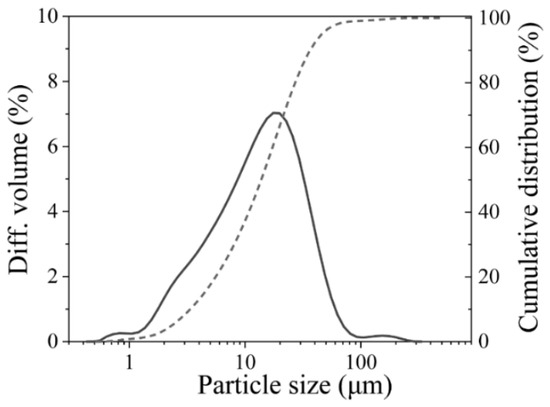
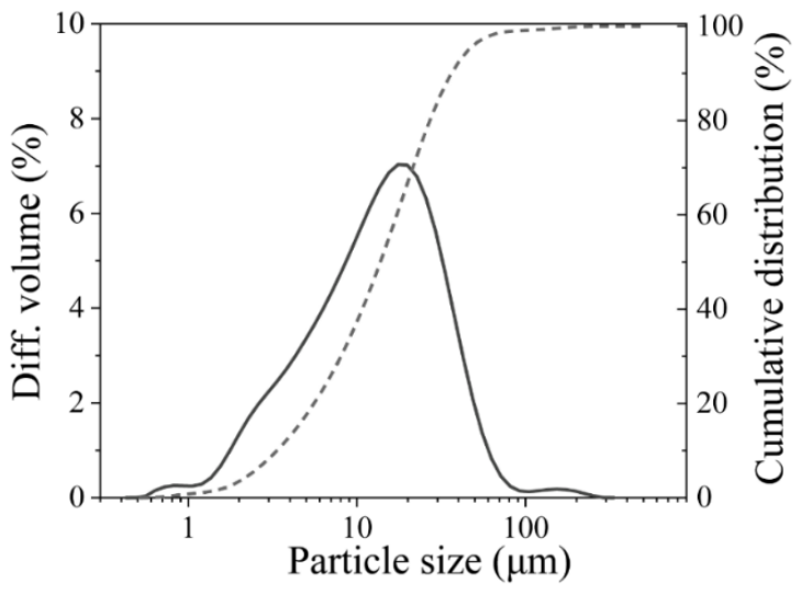
The slag used in the study was supplied from Guigang, Guangxi province, China, with a density of 2722.1 kg/m3. The chemical composition of the slag was determined by X-ray fluorescence (XRF) spectroscopy and is summarized in Table 1. The slag mainly consists of SiO2, Al2O3, CaO, and MgO. Its particle size distribution was characterized using a laser particle size analyzer (Mastersizer 3000), as shown in Figure 1, with a median particle size (D50) of 12.3 μm.
Table 1.
Chemical composition (wt.%) and loss on ignition (LOI) of slag.
Figure 1.
Particle size distribution of slag.
Sodium hydroxide (NaOH) solution and sodium silicate solution (waterglass) were employed as the alkaline activator. The commercial waterglass, supplied by Nanning Jinshan Water Glass Factory (China), contained 9.29 wt% Na2O, 28.22 wt% SiO2, and 62.48 wt% H2O, corresponding to an initial silicate modulus (Ms. = n(SiO2)/n(Na2O)) of 3.14. To obtain the desired activator composition, analytical-grade NaOH pellets were dissolved in the commercial waterglass to reduce the silicate modulus to 2.0. NaOH solution was prepared by dissolving analytical-grade NaOH in deionized water. The waterglass and NaOH solution were equilibrated at room temperature for 24 h before use to ensure complete dissolution and compositional stability. The measured pH values of the NaOH solution and the modified waterglass (Ms = 2.0) were 14.30 and 12.86, respectively.
2.2. Carbonation Pretreatment of Slag
The slag carbonation procedure was adapted from the natural carbonation approach reported in a previous study [24]. Specifically, the slag was subjected to natural carbonation through direct exposure to ambient atmospheric air, without additional CO2 supply or elevated pressure. The nominal atmospheric CO2 concentration was approximately 0.04 vol%, although the CO2 concentration was not actively controlled. The slag was uniformly spread in shallow containers with a layer thickness of approximately 10–15 mm and exposed to the surrounding atmosphere under ambient conditions. The temperature and relative humidity were not continuously monitored during the exposure periods. The slag samples were exposed to these atmospheric conditions for 1, 3, and 6 months to achieve different degrees of natural carbonation. The uncarbonated slag (SL-0) was stored under a nitrogen atmosphere to minimize unintended carbonation and served as the reference material.
According to the carbonation duration, the slag samples were designated as SL-0, SL-1, SL-3, and SL-6, corresponding to exposure periods of 0, 1, 3, and 6 months, respectively.
2.3. Preparation of Aas Grouting Materials
The alkali activator dosage, expressed as Na2O equivalent relative to the mass of all solids (solids including: slag and solid part of activator), was fixed at 4 wt% for all mixtures. Since an excessively high water-to-binder ratio (w/b) improves grout fluidity at the expense of mechanical strength and dimensional stability, a water-to-binder ratio of 0.35 was selected to achieve a balance between workability and hardened performance. In this study, the w/b ratio was defined as the mass ratio of total water to total binder solids. The total water content included both the additional mixing water and the water contained in the alkaline activator solutions, while the binder mass was calculated as the sum of the slag mass and the solid constituents of the alkaline activators, including NaOH and the solids present in the waterglass solution. The detailed mixture proportions are listed in Table 2.
Table 2.
Mix proportions of grouting materials.
The AAS grouting materials were prepared using a laboratory mortar mixer. First, the slag was mixed with the alkaline activator at low speed for 1 min, followed by high-speed mixing for 3 min to obtain a homogeneous grout. The fresh grout was immediately cast into 40 mm × 40 mm × 40 mm cubic molds and cured in a standard curing chamber at 20 ± 1 °C and 95 ± 5% relative humidity for 24 h. After demolding, the specimens were returned to the same curing environment until the designated testing ages, at which compressive strength and other performance tests were conducted.
2.4. Test Methods
2.4.1. Rheological Measurements
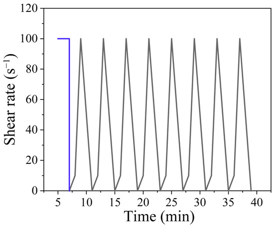
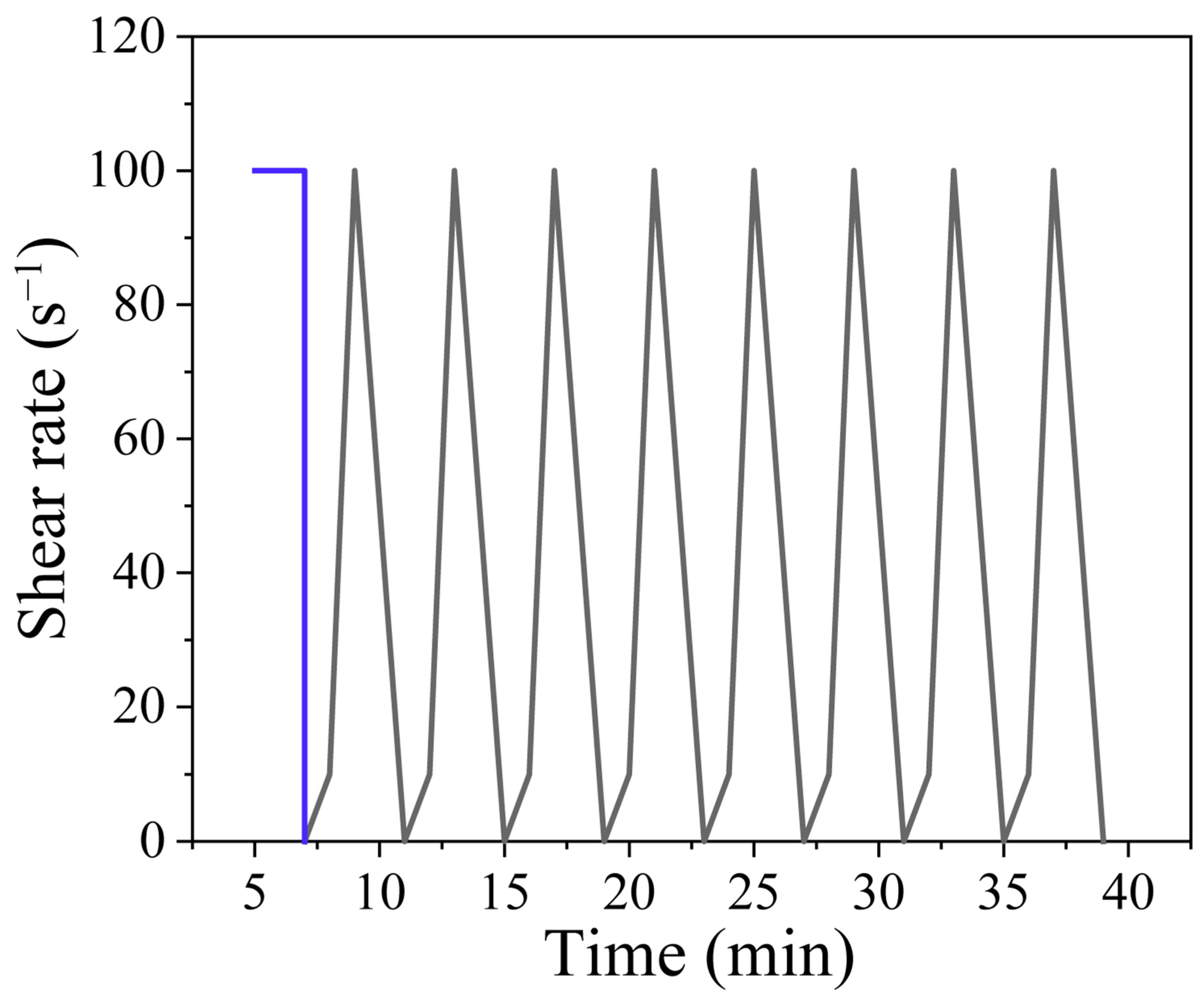
The rheological properties of the freshly prepared AAS were measured using a rotational rheometer (MCR 301, Anton Paar, Graz, Austria) equipped with a concentric cylinder geometry (CC27). Immediately after mixing, the sample was transferred to the rheometer, and the testing protocol is illustrated in Figure 2. Before measurement, the fresh grouting material was pre-sheared at a constant shear rate of 100 s−1 for 120 s to minimize the influence of the initial shear history and establish a reproducible structural state. Subsequently, eight consecutive shear cycles were applied. Each cycle consisted of an increasing shear-rate stage from 0 s−1 to 10 s−1 over 60 s, followed by an increase from 10 s−1 to 100 s−1 over an additional 60 s. The shear rate was then decreased continuously from 100 s−1 to 0 s−1 over 120 s. All rheological measurements were conducted at a controlled temperature of 20 °C. The resulting flow curves were fitted using the modified Bingham model, as expressed in Equation (1), to determine the characteristic rheological parameters of the AAS grouts.
where τ is the shear stress (Pa), γ is the shear rate (s−1), τ0 is the extrapolated apparent yield stress (Pa), μ is the linear plastic viscosity (Pa·s), and c is the pseudoplastic constant. The modified Bingham model was adopted to account for the nonlinear relationship between shear stress and shear rate observed in the experimental flow curves. The descending shear-rate branch was selected for rheological parameter determination. It should be emphasized that τ0 is a model-derived intercept obtained by extrapolation to zero shear rate, rather than a directly measured static yield stress.
τ = τ0 + μγ + cγ2
Figure 2.
Procedure of eight shear cycles.
To investigate the time-dependent rheological behavior of the AAS grouts under conditions representative of pumping and transportation, an additional constant-shear-rate test was conducted at 100 s−1. For this test, the grout was initially mixed using a high-speed disperser at 400 rpm for 1 min, followed by mixing at 1000 rpm for 2 min. The homogeneous grout was immediately transferred to the rheometer, and the evolution of shear stress with shearing time was continuously recorded.
2.4.2. Flowability and Setting Time Test
The flowability of the AAS grouting materials was measured in accordance with the Chinese standard GB/T 8077-2012 [25]. A truncated cone mold with upper and lower diameters of 36 and 60 mm, respectively, and a height of 60 mm was placed at the center of a smooth glass plate measuring 400 mm × 400 mm × 5 mm. The freshly mixed AAS paste was poured into the mold without additional compaction, and the mold was subsequently lifted vertically to allow the paste to spread freely under gravity. After 30 s, the maximum spread diameters in two mutually perpendicular directions were measured, and their average was recorded as the flow spread diameter. Flowability measurements were conducted at elapsed times of 10, 20, and 40 min after mixing to evaluate the time-dependent flowability retention of the AAS grouting materials.
The initial and final setting times of the AAS grouts were determined using a Vicat apparatus based on GB/T 1346-2011 [26], Test methods for water requirement of normal consistency, setting time and soundness of Portland cement. The fresh pastes were prepared at a fixed water-to-binder ratio of 0.35 and immediately placed into Vicat molds. The initial setting time was defined as the elapsed time from the initial contact between slag and the alkaline activator to the point at which the penetration needle stopped 4 ± 1 mm above the base plate. The final setting time was determined when the needle penetrated approximately 0.5 mm into the specimen, and the annular attachment no longer left a visible impression on the surface. The measurements were conducted under controlled curing conditions at 20 ± 1 °C and a relative humidity of 95 ± 5%. Three replicate measurements were performed for each mixture, and the average values were reported.
2.4.3. Assessment of Early Reaction-Product Formation
The early reaction behavior of carbonated slag in the AAS systems was investigated by monitoring changes in the thermal mass-loss characteristics of pastes collected at different reaction times. To terminate the alkali-activation reaction, the fresh pastes collected at the designated ages were subjected to water washing followed by solvent exchange with isopropyl alcohol, according to the procedure reported in Ref. [27].
Approximately 1 g of paste was dispersed in 20 mL of deionized water and mixed to obtain a homogeneous suspension. The suspension was then vacuum-filtered, and the retained solids were rinsed with an additional 20 mL of deionized water to remove residual alkaline species. The solids were subsequently washed with isopropyl alcohol at a solid-to-liquid mass ratio of 1:20 to arrest further reaction. Finally, the treated samples were dried in a vacuum oven to constant mass, ground into powder, and subjected to thermogravimetric analysis. The mass-loss characteristics were used to assess relative changes in thermal behavior rather than to directly quantify the degree of slag reaction.
2.4.4. Compressive Strength Test
The compressive strength of the hardened AAS was determined with reference to GB/T 17671-2021 [28], Test method of cement mortar strength (ISO method). The freshly mixed AAS samples were cast into cubic molds with dimensions of 40 mm × 40 mm × 40 mm. After vibration compaction, the molds were covered with plastic film to prevent moisture loss and placed in a standard curing chamber at 20 ± 1 °C and 95 ± 5% relative humidity.
After 24 h, the specimens were demolded and returned to the same curing environment until the designated testing ages. Six replicate specimens were tested for each mixture, and the average compressive strength was reported.
2.4.5. X-Ray Diffraction (XRD) Analysis
The phase assemblages of the raw materials and hardened AAS samples were characterized by X-ray diffraction using a MiniFlex 600 diffractometer (Rigaku, Tokyo, Japan) equipped with Cu Kα radiation. The operating voltage and current were 40 kV and 15 mA, respectively. The diffraction patterns were collected over a 2θ range of 5–80° at a scanning rate of 5° min−1 and a step size of 0.02°. Powdered raw materials were analyzed directly. Hardened specimens were first crushed, ground into fine powder, and passed through a 200-mesh sieve before measurement.
2.4.6. Fourier Transform Infrared Spectroscopy (FTIR) Analysis
The chemical bonding characteristics of the slag and hardened AAS samples were analyzed using a Fourier-transform infrared spectrometer (Nicolet iS50, Thermo Fisher Scientific, Massachusetts, USA). The powdered sample was mixed with spectroscopic-grade KBr at a mass ratio of 1:100 and thoroughly ground to ensure uniform dispersion. The mixture was subsequently pressed into a transparent pellet. The spectra were collected using a KBr background with a spectral resolution of 1 cm−1 and 32 scans for each specimen.
2.4.7. Thermogravimetric Analysis (TGA)
Thermogravimetric analysis was performed to characterize the thermal decomposition behavior and estimate the relative contents of reaction products and carbonate phases in the AAS samples. The hardened specimens were crushed, finely ground, and passed through a 200-mesh sieve. Approximately 20 mg of powder was placed in an alumina crucible and analyzed using a TGA 2 thermogravimetric analyzer (Mettler Toledo, Zürich, Switzerland). The samples were heated from 30 to 1000 °C at a constant heating rate of 10 °C min−1 under a nitrogen atmosphere.
2.4.8. Field Emission Scanning Electron Microscope and Energy Dispersive Spectroscopy (Fe-Sem/eds)
The microstructural morphology and elemental composition of the hardened AAS samples were examined using a field-emission scanning electron microscope (FE-SEM; SU8220, Hitachi, Tokyo, Japan) equipped with an energy-dispersive X-ray spectrometer. Representative fragments with relatively flat fracture surfaces were selected from the hardened specimens. Before observation, the samples were dried and sputter-coated with gold for 60 s to improve electrical conductivity. FE-SEM observations were conducted at an accelerating voltage of 10 kV and a working distance of approximately 15 mm. Energy-dispersive X-ray spectroscopy was subsequently used to determine the elemental composition of reaction products.
3. Results and Discussion
3.1. Characterization of Cs
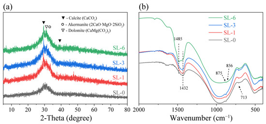
The phase assemblages of CS were characterized by XRD, and the results are presented in Figure 3a. All slag samples exhibit a broad diffuse hump centered between 20° and 40° (2θ), indicating that the predominantly amorphous nature of the slag was retained after carbonation. No obvious change in the position or intensity of the amorphous hump was observed with increasing carbonation duration, suggesting that carbonation did not significantly alter the aluminosilicate glass network within the detection limit of XRD. In contrast, several new crystalline diffraction peaks appeared after carbonation. The diffraction peaks at approximately 29.5° and 39.4° (2θ) are assigned to calcite (CaCO3), while the peak near 31° (2θ) overlaps with the reflections of dolomite (CaMg(CO3)2) and the residual akermanite (2CaO·MgO·2SiO2) phase. The formation of calcite and dolomite confirms that the reactive Ca- and Mg-bearing phases in slag reacted with atmospheric CO2 during carbonation, resulting in the precipitation of carbonate phases.
Figure 3.
(a) XRD patterns and (b) FTIR spectra of slag before and after carbonation.
The chemical structural evolution of the slag before and after carbonation was further investigated by FTIR, as shown in Figure 3b. The broad absorption band centered at approximately 980 cm−1, corresponding to the asymmetric stretching vibration of Si-O-T (T = Si or Al) in the aluminosilicate framework, remained essentially unchanged after carbonation. Thus, no major change in this bulk spectral feature was detected, local near-surface changes cannot be excluded. In contrast, several characteristic carbonate-related absorption bands became increasingly pronounced with increasing carbonation duration. The absorption bands at 1432 cm−1 and 1485 cm−1 correspond to the asymmetric stretching vibration of CO32, while those located at 875 cm−1 and 713 cm−1 are attributed to the O-C-O stretching and bending vibration of carbonate, respectively [29]. The progressive increase in the intensity of these carbonate bands indicates continuous carbonate formation during the carbonation process. In particular, the absorption bands at 1432, 875, and 713 cm−1 are characteristic of calcite, consistent with the XRD results. The additional absorption band observed at 1485 cm−1, which becomes more evident in the SL-6 sample, may be associated with the formation of aragonite during prolonged carbonation [30].
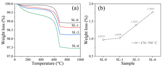
Figure 4 presents the TGA curves of the slag samples and the corresponding weight loss within the temperature range of 470–700 °C, which is mainly associated with the thermal decomposition of carbonate phases. As shown in Figure 4a, all CS samples exhibit a pronounced weight loss in this temperature interval, whereas the uncarbonated slag (SL-0) shows only limited weight loss. The mass loss is primarily attributed to the decomposition of CaCO3, predominantly calcite, together with a small amount of poorly crystalline carbonate phases formed during the carbonation process [31]. The relatively broad carbonate-related mass-loss region of CS is consistent with contributions from carbonate products of differing thermal stability [31].
Figure 4.
(a) TGA and (b) weight loss at temperature regions of 470–700 °C for slag before and after carbonation.
As the carbonation duration increased, the weight loss within 470–700 °C gradually increased (Figure 4b). The continuous increase in carbonate-related mass loss indicates progressive carbonation of the slag, whereby reactive surface Ca-bearing species were gradually converted into thermodynamically stable carbonate phases. Based on the TGA results, the estimated CO2 uptake values of SL-1, SL-3, and SL-6 were 10.34, 14.13, and 17.93 mg CO2 g−1 slag, respectively. These quantitative results, together with the XRD, FTIR, and FE-SEM/EDS results, demonstrate that prolonged atmospheric exposure promoted additional CO2 mineralization.
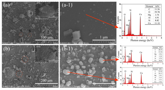
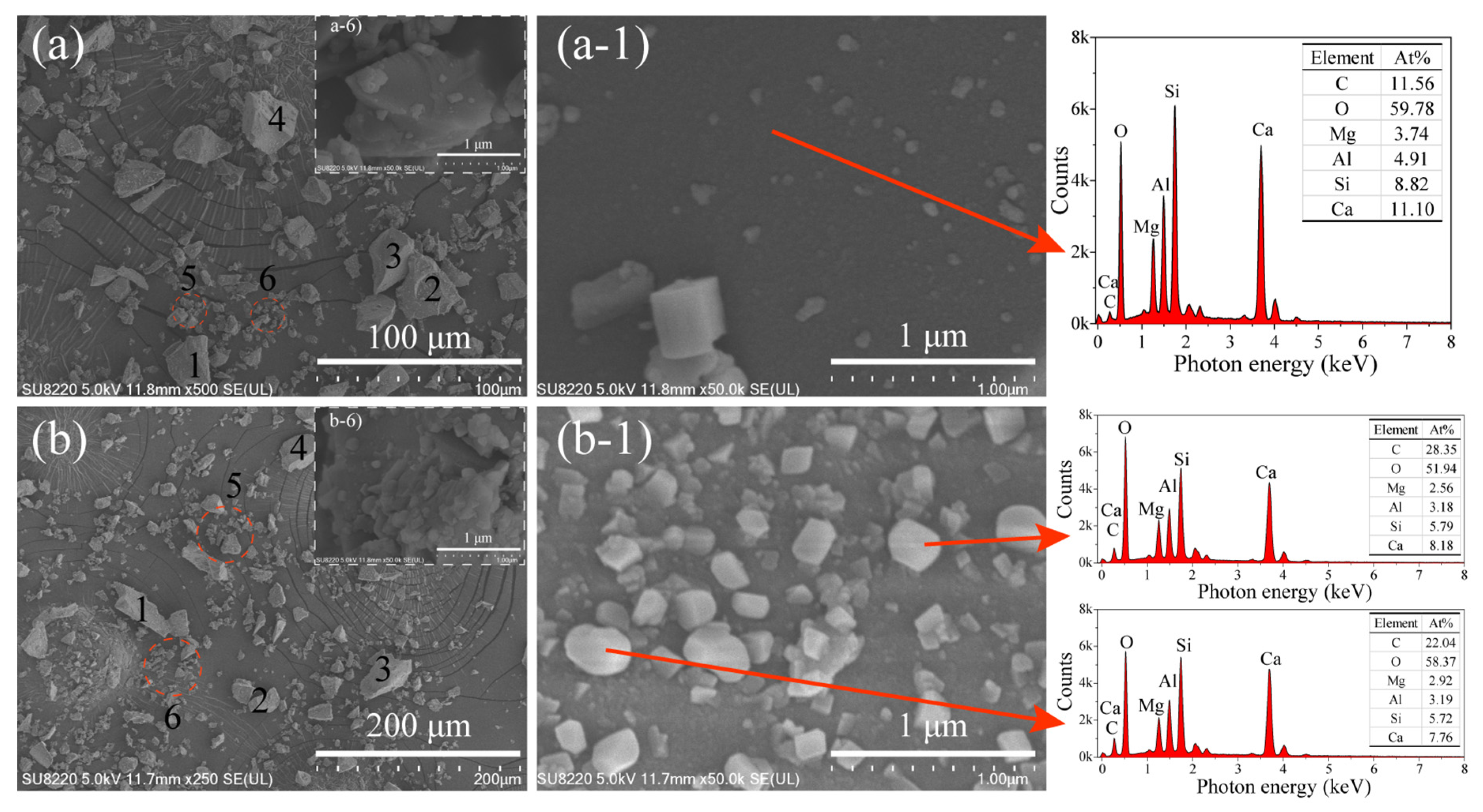
Although XRD, FTIR, and TGA provide valuable information regarding the phase evolution during carbonation, they cannot directly reveal the morphological evolution of the carbonation products on the slag surface. Therefore, FE-SEM/EDS was employed to characterize the surface morphology and elemental composition of the slag before and after carbonation. The corresponding results are presented in Figure 5. As shown in Figure 5a,a-1, the surface of the SL-0 is relatively smooth and dense, exhibiting the typical morphology of rapidly quenched glassy slag with only a few fine particles attached to the surface. The corresponding EDS spectrum mainly consists of O, Ca, Si, Al, and Mg, which is characteristic of Ca–Mg–Al–Si glass.
Figure 5.
FE-SEM images and EDS of (a) SL-0 and (b) SL-6, where (a-1, a-6) and (b-1, b-6) are the corresponding enlarged views. During the SEM testing, the slag particles marked in (a) and (b) were observed.
After carbonation, a pronounced change in the surface morphology of slag particles was observed (Figure 5b,b-1). Numerous nanoparticle precipitates, with sizes ranging from approximately 50 to 300 nm, appeared on the slag surface, resulting in a more irregular surface texture compared with uncarbonated slag. These particles exhibit predominantly rhombohedral- and cubic-like morphologies, while EDS analysis indicated enrichment in Ca and O. Combined with the XRD, FTIR, and TGA results, these observations suggest that the surface precipitates predominantly consist of calcium carbonate. The formation of these carbonate-rich deposits indicates that carbonation modifies the surface morphology and local chemical composition of slag particles.
The formation of these surface precipitates can be attributed to mineral carbonation. During carbonation, Ca-bearing and possibly Mg-bearing reacts with carbonate species, promoting the nucleation and precipitation of carbonate products. These precipitates initially appear as isolated nanoscale nuclei and subsequently grow into discrete rhombohedral crystals with increasing carbonation duration. The enlarged FE-SEM images show discrete particles on the examined slag surfaces.
The combined XRD, FTIR, TGA, and FE-SEM/EDS results consistently demonstrate that carbonation primarily modifies the surface chemistry of slag while preserving its amorphous aluminosilicate framework. XRD analysis shows that the broad amorphous hump remains essentially unchanged after carbonation, indicating that the intrinsic glassy structure of the slag is largely retained. Meanwhile, the appearance of calcite diffraction peaks, together with the characteristic carbonate absorption bands identified by FTIR, confirms the progressive formation of carbonate phases during carbonation. TGA further quantifies this process by revealing a continuous increase in carbonate-related weight loss and CO2 uptake with increasing carbonation duration, indicating the gradual conversion of reactive Ca-bearing species into thermodynamically stable carbonate products. FE-SEM observations provide direct morphological evidence that nanoscale carbonate crystals preferentially precipitate on the slag surface, forming a partially continuous carbonate layer rather than altering the bulk structure of the particles. These observations support carbonation-induced modification of slag, including its near-surface chemistry. Conversion of some Ca-bearing constituents to carbonate could reduce the amount of readily available Ca during early activation.
3.2. Rheological Behavior of AAS Pastes
3.2.1. Rheological Parameters
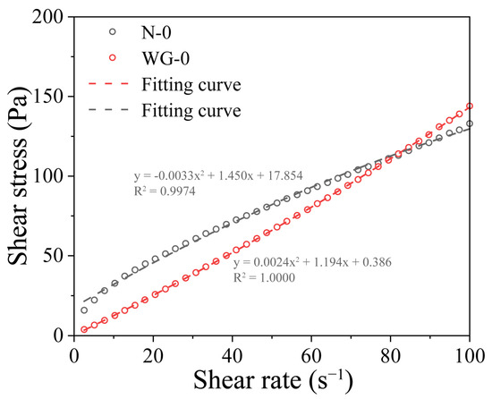
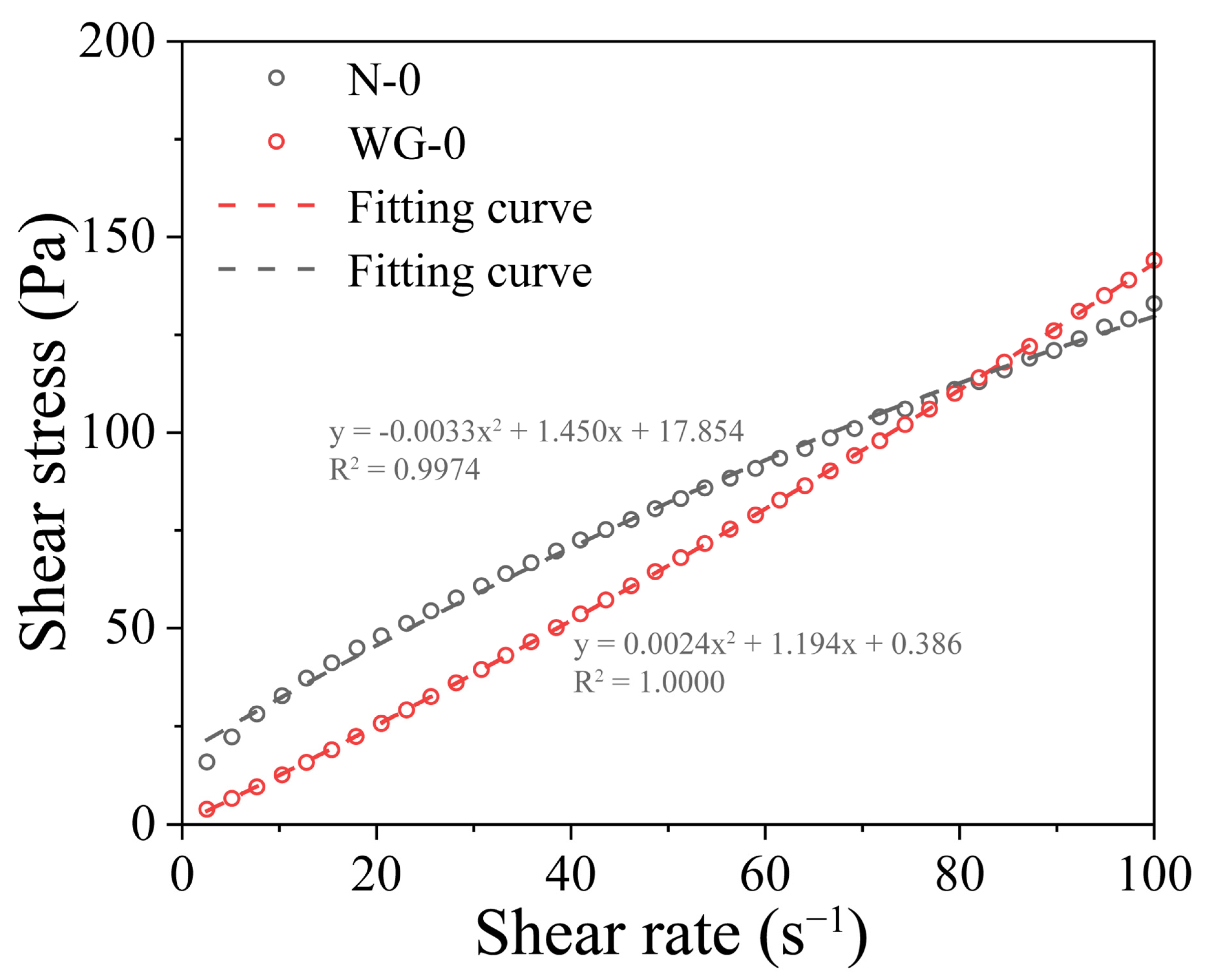
Figure 6 presents representative shear stress-shear rate curves of N-0 and WG-0 samples. The experimental flow curves exhibit nonlinear behavior, indicating that a simple linear Bingham equation may not fully capture the measured rheological response. Therefore, the modified Bingham model, which incorporates a quadratic shear rate term, was adopted to describe the flow behavior. The model provided satisfactory fits to the ramping-down of flow curves, with the correlation coefficients (R2) exceeding 0.99. Accordingly, the modified Bingham equation was used as an empirical fitting approach to obtain comparable apparent rheological parameters under the prescribed testing conditions. The fitted τ0 values should be interpreted as extrapolated apparent yield stresses rather than directly measured static yield stresses.
Figure 6.
Fitting curve for the shear stress-shear rate of grouting materials for N-0 and WG-0.
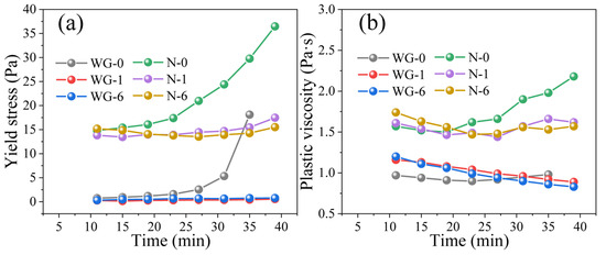
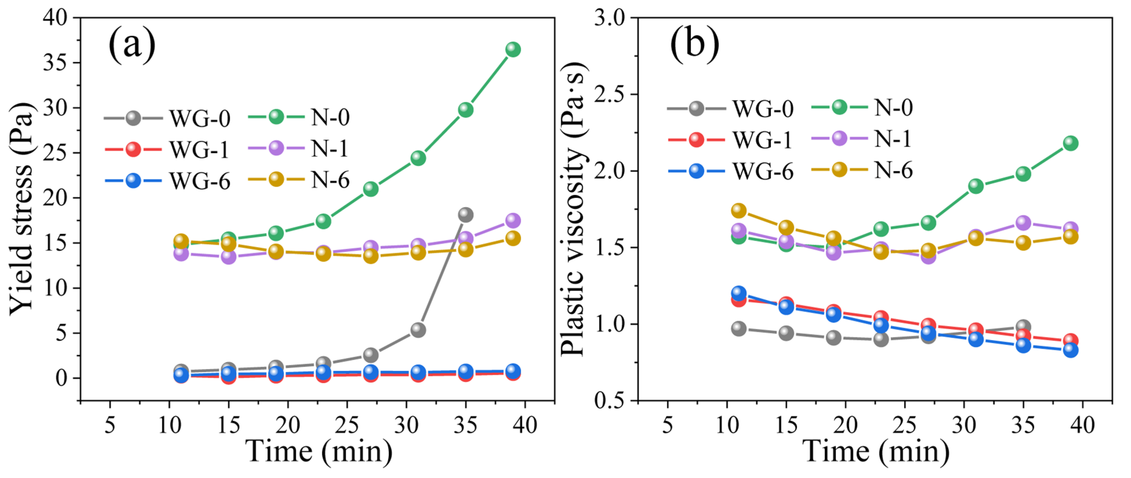
Figure 7 presents the evolution of the apparent yield stress and plastic viscosity of AAS grouting materials obtained from the modified Bingham model. The fitted parameters exhibited pronounced dependence on the carbonation state of the slag and the type of alkaline activator. As shown in Figure 7a, the apparent yield stresses of the uncarbonated-slag systems increased progressively during repeated shear cycles. For N-0, the apparent yield stress increased from 14.8 Pa after the first cycle to 36.5 Pa after the eighth cycle, corresponding to an increase of approximately 147%. Similarly, the apparent yield stress of WG-0 increased from 0.74 Pa to 18.1 Pa. These results indicate an increase in the apparent resistance to flow under the prescribed cyclic shearing conditions. The accumulation of early reaction products may contribute to the increasing flow resistance [12,32], as suggested by the complementary early-age TGA and setting time results, but the individual contributions of chemical reactions and physical restructuring cannot be quantitatively distinguished from the cyclic rheological measurements alone.
Figure 7.
(a) Yield stress and (b) plastic viscosity evolution of AAS grouting materials for the first 40 min.
In contrast, the CS systems exhibited substantially smaller changes in apparent yield stress. For N-1 and N-6, the fitted apparent yield stress remained approximately within 13–17 Pa, while the corresponding values for WG-1 and WG-6 remained below 1 Pa. At such low stress levels, instrument sensitivity, potential wall slip, and uncertainties associated with the measuring geometry and fitting procedure may influence the reliability of the estimated parameters. Therefore, the sub-1 Pa values are primarily considered indicative of low apparent resistance to flow rather than precise measurements of intrinsic yield stress. These results indicate that carbonation pretreatment modifies the time-dependent rheological response and reduces the development of apparent flow resistance under the investigated conditions. This behavior is consistent with delayed early reaction-product accumulation in CS systems, although shear-dependent physical restructuring may also contribute to the observed differences.
The evolution of plastic viscosity is presented in Figure 7b. The N-0 paste exhibited a gradual increase in plastic viscosity with time, reflecting the continuous formation of hydration products and the strengthening of particle interactions. By contrast, the CS systems maintained relatively low plastic viscosity throughout the test. In particular, the plastic viscosity of WG-1 and WG-6 gradually decreased with shearing time, suggesting that the weakly flocculated structure formed in the CS system was continuously disrupted under shear [33]. The different rheological behaviors of the NaOH- and waterglass-activated systems may be associated with their distinct activator chemistries. Although the waterglass activator exhibited a lower pH (12.86) than the NaOH solution (14.30), the two activators also differed in dissolved silicate concentration, silicate speciation, and ionic composition. These differences may collectively influence particle interactions, early reaction-product formation, and the time-dependent rheological behavior of AAS grouts. In particular, dissolved silicate species introduced by waterglass may modify interparticle interactions and the formation of silicate-bearing reaction products.
The different rheological responses of uncarbonated- and carbonated-slag systems show that carbonation alters early structural build-up in fresh AAS. Section 3.1 indicates that carbonation converts reactive surface Ca-bearing species into relatively stable carbonate phases while simultaneously forming a nanoscale carbonate on the slag surface. This modified surface not only consumes readily soluble calcium species but also reduces direct contact between the alkaline activator and the reactive glass phase [34]. Consequently, the initial dissolution of slag and the early precipitation of C-(A)-S-H gels are significantly retarded [35,36], leading to slower structural build-up, lower apparent yield stress, and reduced plastic viscosity. Therefore, the improved rheological performance of the CS systems originates from carbonation-induced regulation of the early reaction products formation rather than from any fundamental change in the intrinsic amorphous structure of the slag.
3.2.2. Evolution of Shear Stress Under Constant Shear Rate
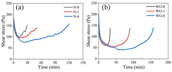
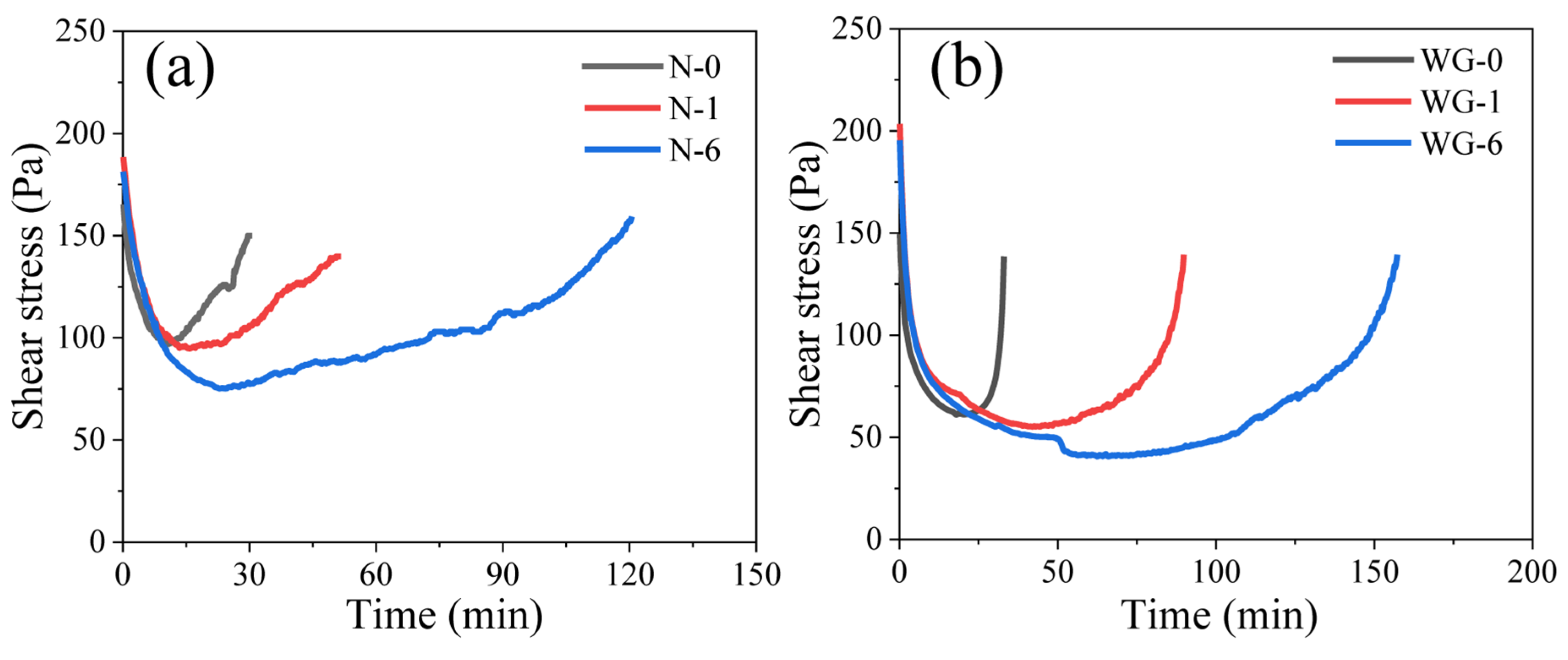
Figure 8 shows the evolution of shear stress of AAS grouting materials under a constant shear rate of 100 s−1. All mixtures exhibited a rapid decrease in shear stress during the initial shearing period, which may be associated with the breakdown and rearrangement of particle structures formed during mixing. The initial shear stresses of the N-0 and WG-0 were approximately 160 Pa and 150 Pa, respectively, whereas those of the corresponding CS systems increased to 185 Pa (NaOH) and 200 Pa (waterglass). This difference suggests that carbonation pretreatment influences the initial resistance to flow. As revealed by FE-SEM observations, carbonation leads to the formation of nanoscale carbonate-rich precipitates and a more irregular slag surface morphology, which may modify particle contacts and interparticle interactions during shearing.
Figure 8.
Shear stress of AAS grouting materials produced from SL and CS: (a) NaOH and (b) waterglass as activators.
Following the initial breakdown, the shear stress entered a quasi-steady plateau before gradually increasing again. Compared with the uncarbonated-slag systems, the CS systems required longer to reach the minimum shear stress and exhibited a longer plateau region before structural rebuilding commenced. Such behavior indicates that carbonation significantly delays the early structural build-up of the AAS grouting material. The delayed structural rebuilding originates from the reduced early reaction product. Carbonate formation and altered near-surface chemistry may contribute to slower early reaction-product accumulation, as also suggested by the time-dependent TGA results in Section 3.4. Delayed formation of C-(A)-S-H-type products provides a plausible explanation for the longer plateau.
Compared with the NaOH-activated systems, the waterglass-activated systems exhibited a longer plateau before the shear stress began to recover. This difference may reflect the combined effects of activator alkalinity, dissolved silicate concentration and speciation, and their influences on early reaction-product accumulation and particle interactions. Increasing carbonation duration further prolonged the plateau under the investigated conditions, indicating a stronger carbonation-associated delay in structural rebuilding. Together, the constant-shear-rate and reaction-product measurements support slower early structural development in the CS systems. By delaying the dissolution of reactive surface species and suppressing the rapid formation of C-(A)-S-H gels [27], carbonation effectively mitigates premature structural build-up, thereby improving the shear stability and workability retention of fresh AAS grouts.
3.3. Flowability and Setting Time
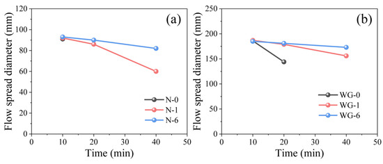
Figure 9 illustrates the evolution of flowability (flow spread diameter) of AAS grouting materials prepared with different activators. The measured flow spread diameter gradually decreased with increasing elapsed time, indicating progressive workability loss due to the early alkali-activation reaction. Notably, the flowability values represent the total spread diameter measured using a mini-slump cone with a bottom diameter of 60 mm. Therefore, a measured value approaching 60 mm indicates negligible additional spreading. As shown in Figure 9a, the NaOH-activated grouting materials exhibited relatively low spread diameters of approximately 91 mm at 10 min, suggesting limited early spreading ability. After 40 min, the spread diameter of N-1 decreased to approximately 60 mm, whereas N-6 maintained a spread diameter of approximately 82 mm. These results indicate that prolonged slag carbonation effectively mitigates flowability loss and improves the workability retention of NaOH-activated AAS grouts.
Figure 9.
Effect of CS on the flow spread diameter of AAS grouting materials: (a) NaOH and (b) waterglass as activators.
As shown in Figure 9b, the waterglass-activated systems exhibited substantially greater flow spread diameters. At 10 min, the spread diameters of the waterglass systems were approximately 186 mm. However, the uncarbonated WG-0 sample exhibited a rapid decrease in spread diameter to approximately 144 mm after 20 min, indicating a pronounced loss of workability. In contrast, the CS systems retained significantly greater flowability, with WG-1 and WG-6 maintaining spread diameters of approximately 156 and 173 mm, respectively, after 40 min. The improved flowability retention with increasing carbonation duration is consistent with the rheological results, demonstrating that carbonation effectively delays the early structural build-up of AAS grouting materials. Consequently, the carbonation-induced suppression of early slag reactivity, combined with the dispersing effect of waterglass [37], contributes to improved flowability retention and an extended workable period.
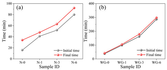
The initial setting time and final setting times of AAS grouting materials are presented in Figure 10. As shown in Figure 10a, the initial and final setting times of N-0 were approximately 16 min and 35 min, respectively, indicating a rapid transition from the fresh to the hardened state. Carbonation pretreatment markedly prolonged both setting times, and the retardation effect became more pronounced with increasing carbonation duration. Specifically, the initial setting time of the NaOH-activated system increased from 16 min for N-0 to 41 min for N-1 and further to 80 min for N-6, while the corresponding final setting time increased to approximately 92 min for N-6. A similar trend was observed in the waterglass-activated systems (Figure 10b), in which the initial and final setting times increased from 28 min and 40 min in the WG-0 progressively with carbonation duration, reaching approximately 286 and 300 min, respectively, for WG-6.
Figure 10.
Effect of CS on the setting time of AAS grouting materials: (a) NaOH and (b) waterglass as activators.
The rapid setting behavior observed in N-0 and WG-0 is consistent with previous studies on AAS systems [17,38]. In highly alkaline AAS, the alkaline environment promotes the dissolution of reactive Ca-, Si-, and Al-bearing species from the slag, accelerating early C-(A)-S-H-type reaction product formation, which strengthens interparticle connections, accelerates structural build-up, and leads to rapid setting. This interpretation is supported by the rheological results (Figure 7), which show a rapid increase in the yield stress of N-0 and WG-0, which indicate the rapid accumulation of early reaction products.
In contrast, carbonation pretreatment prolonged setting and modified the early structural development of the AAS systems. XRD, FTIR, TGA, and FE-SEM/EDS support carbonate formation and local Ca-rich surface deposition; they do not establish a continuous layer. Conversion of some Ca-bearing constituents to carbonate, together with associated changes in near-surface chemistry, may reduce the availability of species involved in early C-(A)-S-H formation [19,39]. The slower accumulation of thermally labile reaction products discussed in Section 3.4 is consistent with this interpretation, although dissolution and gel-nucleation rates were not measured directly. The observed delay became more pronounced with carbonation duration and was particularly large in the waterglass-activated systems.
3.4. Early Reactivity of Cs
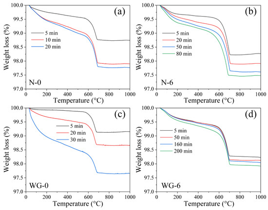
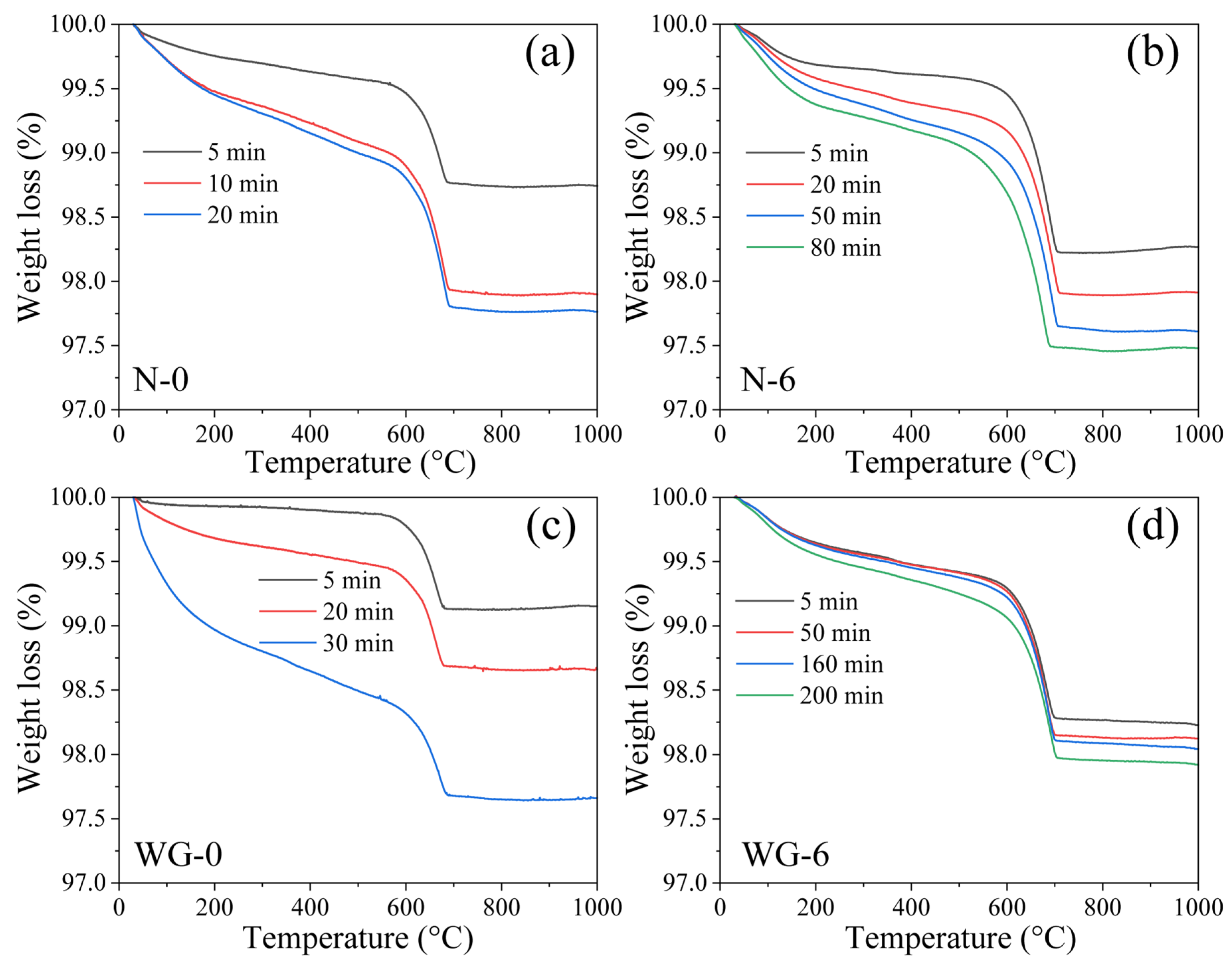
Figure 11 presents the TGA curves of the NaOH-activated (N-0 and N-6) and waterglass-activated (WG-0 and WG-6) grouting materials at different reaction times; the corresponding weight losses are summarized in Table 3. The weight loss between 30 and 500 °C is mainly associated with the dehydration of C-(A)-S-H gel and other hydration products and therefore reflects the extent of the alkali-activation reaction [27]. Within the NaOH-activated series, this mass loss increased from 0.423% at 5 min to 1.000% at 20 min for N-0, compared with 0.417% to 0.679% over the same interval for N-6. Within the waterglass-activated series, WG-0 increased from 0.118% at 5 min to 1.506% at 30 min, whereas WG-6 changed from 0.580% at 5 min to 0.585% at 50 min and reached 0.750% at 200 min. These observations indicate time-dependent changes in the thermal mass-loss characteristics of the pastes, which are consistent with the progressive formation and evolution of hydrated reaction products. The slower early increase in CS paste weight loss is consistent with the prolonged shear-stress plateau (Figure 8) and delayed setting (Figure 10). These measurements suggest that carbonation changes the timing of early reaction-product formation and structural build-up. Combined with the XRD, FTIR, TGA, and FE-SEM/EDS results, these observations indicate that carbonation pretreatment modifies the early reaction behavior of slag while largely preserving its predominantly amorphous aluminosilicate structure. The formation of carbonate phases and the associated changes in the chemical characteristics of reactive Ca-bearing constituents may influence the availability of calcium species and their subsequent participation in early alkali-activation reactions, thereby reducing early structural build-up, prolonging the setting time, and improving the rheological performance and workability retention of AAS.
Figure 11.
TGA curves of the AAS grouting materials with different reaction times: (a,b) NaOH and (c,d) waterglass.
Table 3.
Weight loss (%) of the AAS grouting materials with different reaction times measured by TGA.
3.5. Compressive Strength
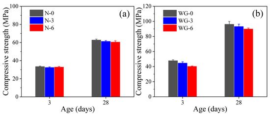
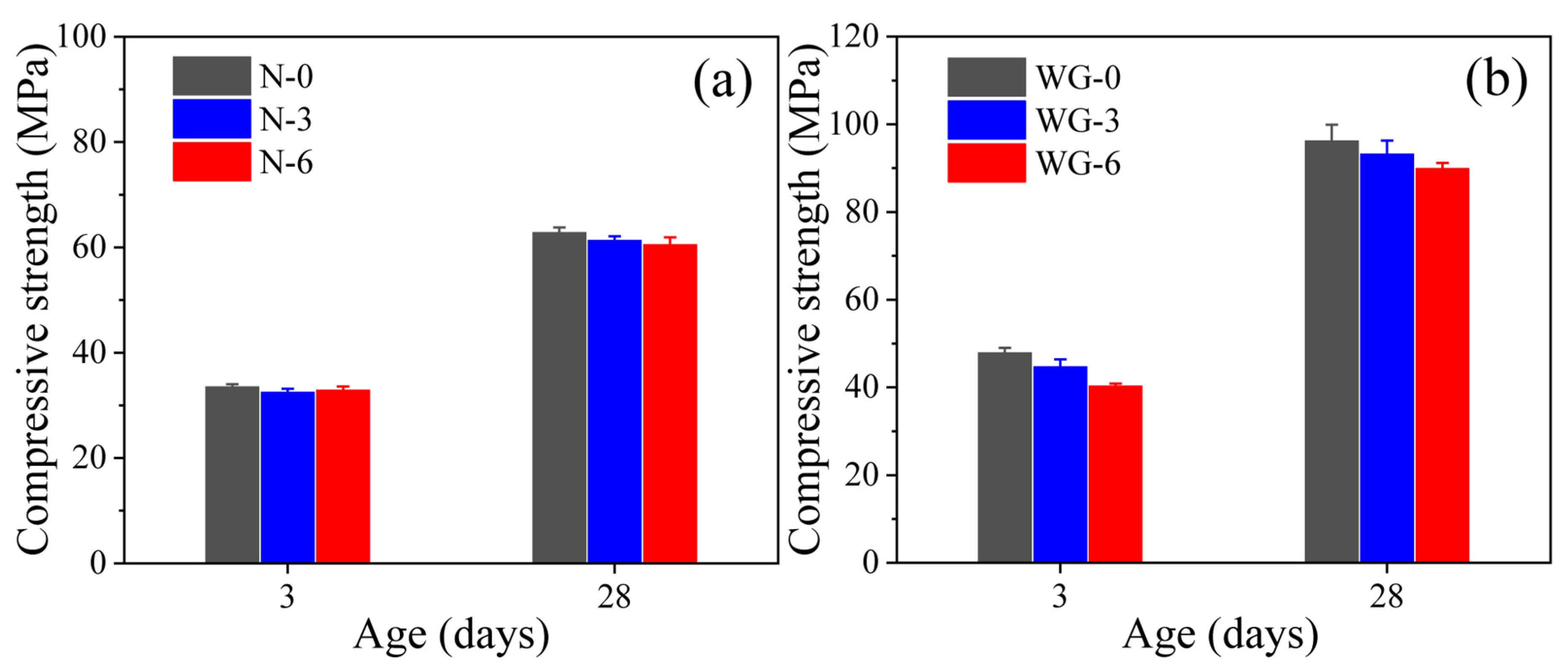
Figure 12 presents the compressive strengths of AAS grouting materials after 3-day and 28-day curing. The 3-day and 28-day strengths of NaOH systems ranged from 32.9 to 33.5 MPa and from 60.5 to 62.8 MPa, respectively, while those of the waterglass systems ranged from 40.3 to 47.9 MPa and from 89.9 to 96.2 MPa. These results indicate that the macroscopic mechanical performance was largely preserved under the investigated curing conditions.
Figure 12.
Compressive strength of AAS grouting materials with: (a) NaOH and (b) waterglass.
In contrast, carbonation pretreatment slightly reduced the 3-day strength of waterglass systems. Compared with WG-0, the 3-day strength decreased from 47.9 MPa to 44.7 MPa for WG-3 and 40.3 MPa for WG-6, corresponding to reduction of 6.7% and 15.9%, respectively. This trend is consistent with slower early reaction-product accumulation in the carbonated-slag systems. The lower alkalinity of the waterglass activator may further contribute to the observed response [40,41], although the present measurements do not isolate the individual effects. The NaOH-activated systems showed little change in 3-day strength under the investigated conditions. Despite these differences in early-age mechanical performance, the carbonated slag systems achieved compressive strengths comparable to those of the uncarbonated reference systems after 28 days of curing. This observation suggests that the effects of carbonation pretreatment on early structural development did not substantially compromise the load-bearing capacity of the hardened materials at the investigated age.
3.6. Microstructure Characterization of Aas
3.6.1. XRD
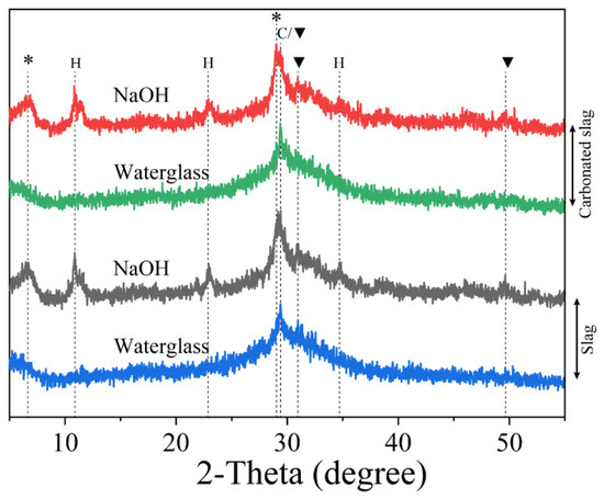
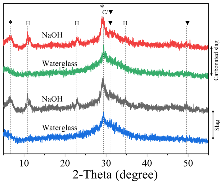
Figure 13 presents the XRD patterns of the AAS grouting materials after 28 days of curing. All samples exhibit a broad diffuse hump centered at approximately 29° (2θ), which is mainly associated with C-(A)-S-H gel and partially overlaps with the principal diffraction peak of calcite. The NaOH-activated grouting materials display distinct peaks near 7° and 29° (2θ), characteristic of C-S-H(I) gel (PDF #034-0002) [32], as well as peaks at 12°, 22°, and 35° (2θ) were attributed to hydrotalcite (Mg6Al2(CO3)(OH)16·4(H2O), PDF #014-0191). In contrast, these reflections are much less pronounced in the waterglass-activated systems, suggesting a lower degree of crystallinity of the reaction products [42]. No significant differences in the identified crystalline phase assemblage were observed between the uncarbonated and carbonated slag systems. The diffraction peak near 29.4° (2θ), associated with calcite, may include contributions from carbonate phases already present in the carbonated slag and those formed during subsequent curing [43].
Figure 13.
XRD patterns of NaOH- and waterglass-activated grouting materials (C: Calcite; *: C-S-H (I); ▼: C-A-S-H; H: Mg6Al2CO3(OH)16·4H2O).
3.6.2. FTIR
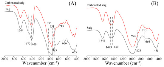
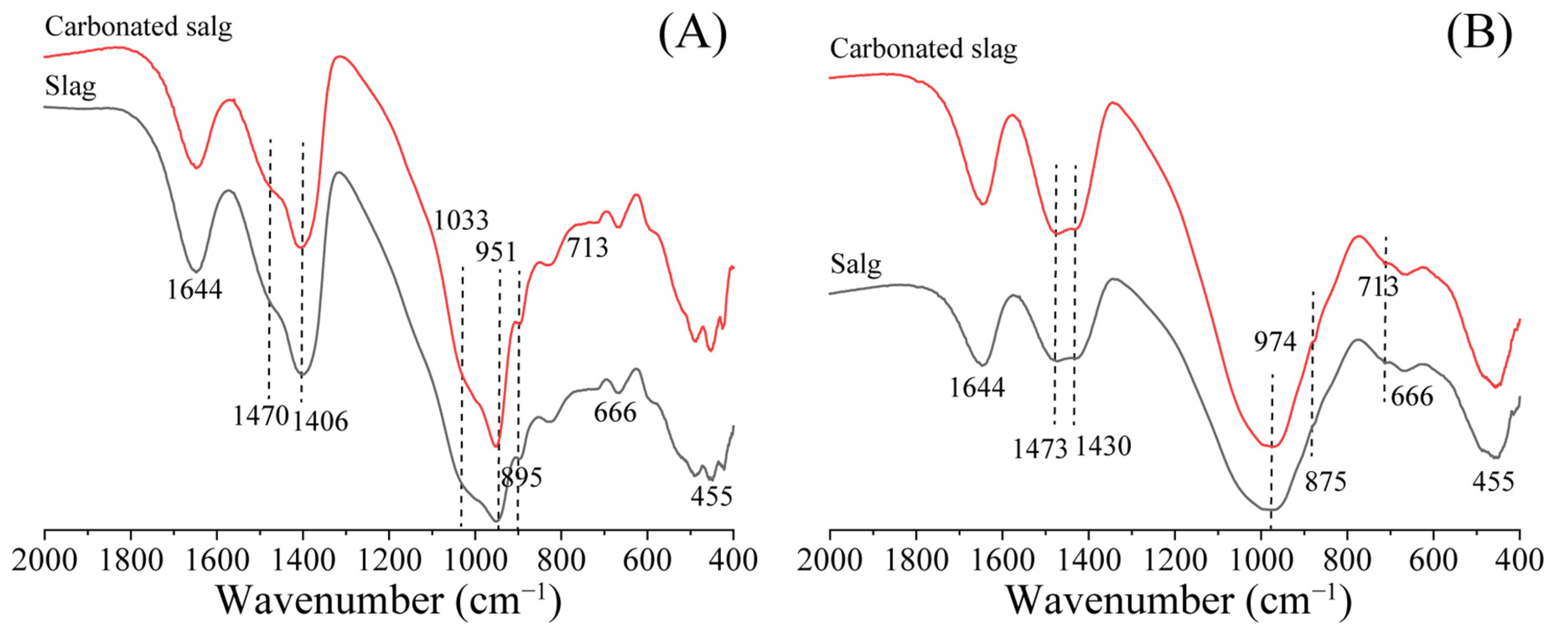
Figure 14 presents the FTIR spectra of the AAS grouting materials after 28 days of curing. Within the same activator system, carbonation causes no noticeable changes in either the positions or profiles of the characteristic absorption bands, indicating that the chemical structure of the reaction products remains essentially unchanged. The main absorption bands are summarized in Table 4. For NaOH-activated grouting material, the bands at 1406 cm−1 and 1470 cm−1 are assigned to the stretching vibration of CO32−, while the corresponding bands for the waterglass-activated systems appear at 1431 cm−1 and 1473 cm−1. The principal Si-O-T (T = Si or Al) stretching band occurs at 951 cm−1 for the NaOH-activated systems and shifts to 974 cm−1 in waterglass-activated systems, reflecting the formation of a more Si-rich C-(A)-S-H gel [38,44]. The additional band at 1033 cm−1 in the NaOH-activated grouting material is attributed to the incorporation of Na into the aluminosilicate gel network [45]. Overall, the FTIR results reveal no pronounced changes in the main characteristic bands of the AAS following slag carbonation pretreatment within the same activator. These observations suggest that the principal bonding environments of the reaction products remain broadly similar after 28 days of curing.
Figure 14.
FTIR spectra of AAS grouting materials: (A) NaOH and (B) waterglass.
Table 4.
The typical bands of AAS grouting materials.
3.6.3. Fe-Sem/eds
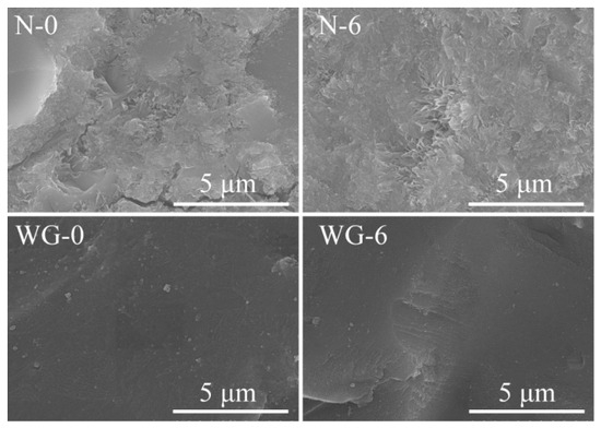
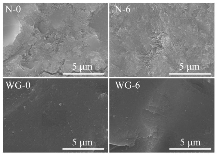
Figure 15 shows the FE-SEM images of AAS grouting materials. Differences in the observed microstructure morphologies can be identified between the two activation systems. The NaOH-activated grouting materials exhibit a relatively porous honeycomb-like gel network, whereas the waterglass-activated systems develop a denser and more homogeneous matrix. The higher compactness of the latter is consistent with its superior compressive strength. Under the same activator, no obvious differences in gel morphology are observed between the uncarbonated and carbonated slag systems, indicating that carbonation has little influence on the morphology of the reaction products at the later curing stage.
Figure 15.
SEM images of AAS grouting materials from SL and CS with different activators.
The EDS results (Table 5) show that the analyzed regions mainly contain Ca, Si, Al, and Na, which is consistent with the coexistence of calcium aluminosilicate-based products. Moreover, the measured Al/Si and Ca/Si ratios exhibit variations among the selected analysis points. In general, the waterglass-activated samples show lower local Ca/Si ratios than the NaOH-activated samples, which may be associated with differences in activator composition and the availability of dissolved silicate species. The resulting Si-rich products possess a higher degree of polymerization and a denser microstructure, which contributes to the compressive strength of the waterglass-activated grouting materials [48].
Table 5.
Local elemental compositions (%) obtained from EDS analysis of two selected regions in each hardened AAS sample.
3.7. Time-Dependent Grout Infiltration into Porous Asphalt Concrete
To evaluate the effect of CS on the grouting performance of AAS materials, the grouting saturation was estimated from the mass increase in porous asphalt concrete (PAC) after grouting. The PAC specimens (φ101.6 mm × 63.5 mm) were supplied by Guangxi Transportation Science and Technology Group Co., Ltd, Nanning, Guangxi, Chin. The basic parameters of the specimens are summarized in Table 6. The grouting saturation was calculated using the following equation:
where G is the grouting saturation, (%); m1 and m2 are the masses of PAC before and after grouting, (g); ρ is the density of fresh grouting material (ρ = 1.86 g·cm−3); v is the volume of the PAC (cm3); ε represents the connected porosity in the PAC (%).
Table 6.
Basic parameters of porous asphalt concretes.
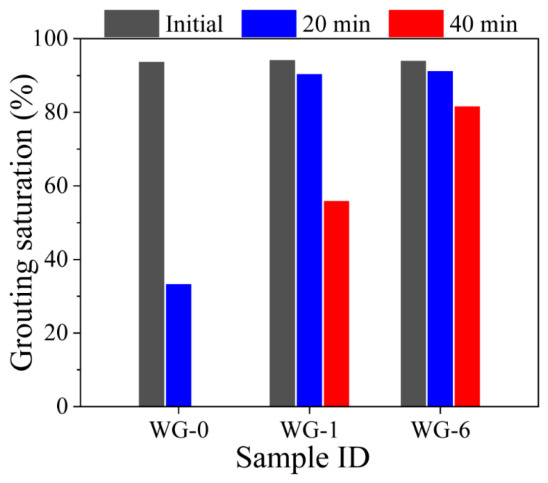
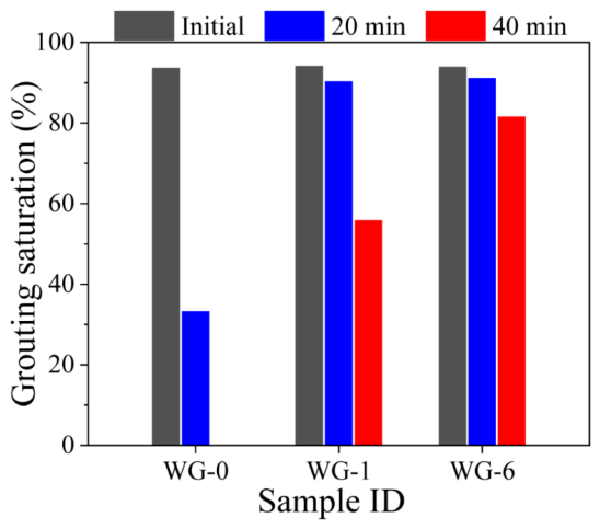
The results of the grouting saturation are presented in Figure 16. All three mixtures exhibited initial grouting saturations exceeding 90%, indicating excellent initial flowability and effective penetration into the interconnected pores of PAC. However, the grouting saturation gradually decreased with standing time because of the progressive loss of flowability induced by alkali activation. Among the mixtures, the WG-0 specimen showed the most pronounced decline, with the grouting saturation decreasing to approximately 33% after 20 min. This substantial reduction indicates a relatively short effective working period for the uncarbonated AAS grout. In contrast, the WG-1 specimen maintained a grouting saturation of approximately 90% after 20 min, although it decreased to approximately 55% after 40 min. Among the investigated mixtures, WG-6 exhibited the highest sustained infiltration performance, retaining approximately 90% and 80% saturation after 20 and 40 min, respectively. The improved sustained infiltration capability is consistent with the enhanced flowability retention and prolonged setting times in the CS systems. The formation of carbonate-rich phases during slag carbonation is associated with modifications in early reaction behavior and slower development of flow resistance, which may contribute to the extended period of effective infiltration.
Figure 16.
Grouting saturation of grouting materials with CS at different times.
4. Conclusions
In this study, the physicochemical characteristics of CS and its influence on the fresh and hardened properties of AAS grouting materials were investigated. The following conclusions can be drawn:
- (1)
- Carbonation modifies the surface physicochemical characteristics of slag without altering its amorphous aluminosilicate framework. Discrete Ca-rich deposits on the slag surface reduce slag reactivity and suppress early product formation.
- (2)
- Carbonated slag effectively regulates the early reaction kinetics of AAS grouting materials. Compared with the uncarbonated controls, the carbonated-slag systems generally showed slower yield-stress development, longer shear-stress plateaus, improved flowability retention, and prolonged setting times. The time-dependent TGA results were consistent with slower early reaction-product accumulation.
- (3)
- Carbonation pretreatment substantially improved the sustained grouting performance of AAS. In the waterglass-activated system, grouting saturation after 20 min was approximately 33% for WG-0 and approximately 90% for the CS mixtures under the investigated conditions.
- (4)
- Carbonation had a limited effect on 28-day compressive strength. The waterglass-activated systems showed some reduction in 3-day strength with longer carbonation, whereas the 28-day strengths remained within 60.5–62.8 MPa for NaOH activation and 89.9–96.2 MPa for waterglass activation. Carbonation pretreatment can improve fresh-state workability while largely preserving the mechanical performance at 28 days.
Author Contributions
J.X.: Writing—original draft, Writing—review and editing, Validation, Supervision, Project administration, Methodology, Data curation, Software, Funding acquisition. P.Y.: Data curation, Funding acquisition, Software. Q.W.: Data curation. Y.H.: Writing—review and editing, Validation, Project administration. L.L.: Resources, Investigation, Formal analysis, Data curation. X.C.: Writing—review and editing, Investigation, Formal analysis. All authors have read and agreed to the published version of the manuscript.
Funding
This research was funded by the Joint Fund of Henan Province Science and Technology R&D Program (245200810065, 252103810036), Research Initiation Funding Projects of Henan Academy of Sciences (241818087), and the National Natural Science Foundation of China (grant: 52262002).
Data Availability Statement
Data will be made available on request.
Conflicts of Interest
The authors declare that they have no known competing financial interests or personal relationships that could have appeared to influence the work reported in this paper.
References
- Li, R.; Wei, Y.; Cai, W.; Liu, Y.; You, K.; Yu, Y. Tracking cement transportation carbon emissions in China: Historical assessment and future simulation. Environ. Impact Assess. Rev. 2025, 110, 107696. [Google Scholar] [CrossRef] [Scilit]
- Yang, C.; Liu, J.; Liu, L.; Kuang, L.; Zhang, S.; Chen, Z.; Li, J.; Shi, C. Effects of different activators on autogenous shrinkage of alkali-activated slag cement. Constr. Build. Mater. 2024, 446, 138018. [Google Scholar] [CrossRef] [Scilit]
- Provis, J.L. Alkali–activated materials. Cem. Concr. Res. 2018, 114, 40–48. [Google Scholar] [CrossRef] [Scilit]
- Tian, H.; Song, Y.; Zhu, X.; Helian, Y.; Wang, H.; Kong, X. Retardation mechanism of alkali-activated slag by organo-silanes: From surface interaction to gel evolution. Cem. Concr. Compos. 2026, 169, 106536. [Google Scholar] [CrossRef] [Scilit]
- Ye, H.; Chen, Z.; Huang, L. Mechanism of sulfate attack on alkali–activated slag: The role of activator composition. Cem. Concr. Res. 2019, 125, 105868. [Google Scholar] [CrossRef] [Scilit]
- Sun, K.; Ali, H.A.; Xuan, D.; Poon, S. Sulfuric acid resistance behaviour of alkali-activated slag and waste glass powder blended precursors. Cem. Concr. Compos. 2024, 145, 105319. [Google Scholar] [CrossRef] [Scilit]
- Arslan, F.; Dener, M.; Karataş, M.; Benli, A. Optimization, high-temperature resistance, and sulfate durability of basalt powder–blended alkali-activated slag mortars. J. Build. Eng. 2026, 119, 115236. [Google Scholar] [CrossRef] [Scilit]
- Duxson, P.; Provis, J.L.; Lukey, G.C.; van Deventer, J.S. The role of inorganic polymer technology in the development of ‘green concrete’. Cem. Concr. Res. 2007, 37, 1590–1597. [Google Scholar] [CrossRef] [Scilit]
- Zhang, S.; Zhang, Z.; Huang, J. Experimental and molecular dynamics insights into the degradation mechanism of alkali-activated cementitious grouting material under compound erosion. Case Stud. Constr. Mat. 2026, 24, e06037. [Google Scholar] [CrossRef] [Scilit]
- Gao, Y.; Xu, W.; Huang, G.; Li, W.; Cheng, Z. Research on early-age properties and hydration mechanisms of slaked lime-sodium carbonate activated GGBS-sulphoaluminate cement grouting material. Constr. Build. Mater. 2026, 519, 145888. [Google Scholar] [CrossRef] [Scilit]
- Li, X.; Feng, X.; Zhou, Y.; Yang, C.; Liu, X. Formulation and properties of a new cleaner double liquid alkali-activated grouting material. J. Clean. Prod. 2023, 426, 138878. [Google Scholar] [CrossRef] [Scilit]
- Tsuyuki, N.; Koizumi, K. Granularity and Surface Structure of Ground Granulated Blast-Furnace Slags. J. Am. Ceram. Soc. 1999, 82, 2188–2192. [Google Scholar] [CrossRef] [Scilit]
- Duxson, P.; Provis, J.L. Designing Precursors for Geopolymer Cements. J. Am. Ceram. Soc. 2008, 91, 3864–3869. [Google Scholar] [CrossRef] [Scilit]
- Li, Y.; Xu, W.; Gao, Y.; Liu, J. Development of full solid waste-based grouting materials using calcium carbide slag-activated red mud/GGBS. Constr. Build. Mater. 2025, 483, 141827. [Google Scholar] [CrossRef] [Scilit]
- Lu, C.; Zhang, Z.; Shi, C.; Li, N.; Jiao, D.; Yuan, Q. Rheology of alkali-activated materials: A review. Cem. Concr. Compos. 2021, 121, 104061. [Google Scholar] [CrossRef] [Scilit]
- Li, P.; Chen, D.; Jia, Z.; Li, Y.; Li, S.; Yu, B. Effects of Borax, Sucrose, and Citric Acid on the Setting Time and Mechanical Properties of Alkali-Activated Slag. Materials 2023, 16, 3010. [Google Scholar] [CrossRef] [Scilit] [PubMed]
- Huang, X.; Li, J.; Zhang, Z.; Yang, H.; Wang, H.; Xue, Q. Strength evolution and microstructure of alkali-activated ultra-fine slag in low-temperature environments. Constr. Build. Mater. 2024, 435, 136852. [Google Scholar] [CrossRef] [Scilit]
- Li, N.; Shi, C.; Zhang, Z. Understanding the roles of activators towards setting and hardening control of alkali-activated slag cement. Compos. Part B Eng. 2019, 171, 34–45. [Google Scholar] [CrossRef] [Scilit]
- Kim, G.M.; Khalid, H.R.; Kim, H.J.; Lee, H.K. Alkali activated slag pastes with surface-modified blast furnace slag. Cem. Concr. Compos. 2017, 76, 39–47. [Google Scholar] [CrossRef] [Scilit]
- Pan, S.Y.; Chen, Y.H.; Fan, L.S.; Kim, H.; Gao, X.; Ling, T.C.; Chiang, P.C.; Pei, S.L.; Gu, G.W. CO2 mineralization and utilization by alkaline solid wastes for potential carbon reduction. Nat. Sustain. 2020, 3, 399–405. [Google Scholar] [CrossRef] [Scilit]
- Pan, S.Y.; Chiang, P.C.; Chen, Y.H.; Tan, C.S.; Chang, E.E. Ex Situ CO2 Capture by Carbonation of Steelmaking Slag Coupled with Metalworking Wastewater in a Rotating Packed Bed. Environ. Sci. Technol. 2013, 47, 3308–3315. [Google Scholar] [CrossRef] [Scilit] [PubMed]
- Mutti, M.; Joseph, S.; Snellings, R.; Cizer, O. Effect of slag pre-carbonation on its early-age reactivity in alkali activated binder. Constr. Build. Mater. 2024, 411, 134413. [Google Scholar] [CrossRef] [Scilit]
- Nie, X.; He, Y.; Kuang, L.; Tian, C.; Cui, X.; Liu, L. Effect of temperature on CO2-modified slag and regulation of setting and hardening of slag modified by alkali activation. Constr. Build. Mater. 2026, 514, 145422. [Google Scholar] [CrossRef] [Scilit]
- Sorrentino, G.P.; Zanoletti, A.; Ducoli, S.; Zacco, A.; Iora, P.; Invernizzi, C.M.; Marcoberardino, G.D.; Depero, L.E.; Bontempi, E. Accelerated and natural carbonation of a municipal solid waste incineration (MSWI) fly ash mixture: Basic strategies for higher carbon dioxide sequestration and reliable mass quantification. Environ. Res. 2023, 217, 114805. [Google Scholar] [CrossRef] [Scilit] [PubMed]
- GB/T 8077-2112; Methods for Testing Uniformity of Concrete Admixture. China Standards Press: Beijing, China, 2013.
- Gb/T 1346-2011; Test Methods for Water Requirement of Normal Consistency, Setting Time and Soundness of the Portland Cement. China Standards Press: Beijing, China, 2011.
- Palacios, M.; Gismera, S.; Alonso, M.M.; d’Espinose de Lacaillerie, J.B.; Lothenbach, B.; Favier, A.; Brumaud, C.; Puertas, F. Early reactivity of sodium silicate-activated slag pastes and its impact on rheological properties. Cem. Concr. Res. 2021, 140, 106302. [Google Scholar] [CrossRef] [Scilit]
- GB/T 17671-2021; Test Mothod of Cement Mortar Strength (ISO Method). China Standards Press: Beijing, China, 2021.
- Farhadi-Khouzani, M.; Chevrier, D.M.; Zhang, P.; Hedin, N.; Gebauer, D. Water as the Key to Proto-Aragonite Amorphous CaCO3. Angew. Chem. Int. Ed. 2016, 55, 8117–8120. [Google Scholar] [CrossRef] [Scilit] [PubMed]
- Shi, Z.; Shi, C.; Wan, S.; Li, N.; Zhang, Z. Effect of alkali dosage and silicate modulus on carbonation of alkali–activated slag mortars. Cem. Concr. Res. 2018, 113, 55–64. [Google Scholar] [CrossRef] [Scilit]
- Thiery, M.; Villain, G.; Dangla, P.; Platret, G. Investigation of the carbonation front shape on cementitious materials: Effects of the chemical kinetics. Cem. Concr. Res. 2007, 37, 1047–1058. [Google Scholar] [CrossRef] [Scilit]
- Mehdizadeh, H.; Kani, E.N.; Sanchez, A.P.; Fernandez-Jimenez, A. Rheology of activated phosphorus slag with lime and alkaline salts. Cem. Concr. Res. 2018, 113, 121–129. [Google Scholar] [CrossRef] [Scilit]
- Lu, C.F.; Zhang, Z.H.; Hu, J.; Yu, Q.J.; Shi, C.J. Effects of anionic species of activators on the rheological properties and early gel characteristics of alkali-activated slag paste. Cem. Concr. Res. 2022, 162, 106968. [Google Scholar] [CrossRef] [Scilit]
- Bernal, S.A.; Provis, J.L.; Myers, R.J.; San Nicolas, R.; van Deventer, J.S. Role of carbonates in the chemical evolution of sodium carbonate-activated slag binders. Mater. Struct. 2015, 48, 517–529. [Google Scholar] [CrossRef] [Scilit]
- Ortega-Zavala, D.E.; Santana-Carrillo, J.L.; Burciaga-Díaz, O.; Escalante-García, J.I. An initial study on alkali activated limestone binders. Cem. Concr. Res. 2019, 120, 267–278. [Google Scholar] [CrossRef] [Scilit]
- Perez-Cortes, P.; Escalante-Garcia, J.I. Design and optimization of alkaline binders of limestone-metakaolin-A comparison of strength, microstructure and sustainability with portland cement and geopolymers. J. Clean. Prod. 2020, 273, 123118. [Google Scholar] [CrossRef] [Scilit]
- Ma, Y.; Zhang, B.B.; Wang, B.J.; Lin, X.J.; Zhu, J.Q.; Huang, P.; Ji, T. Fluidity, mechanical properties, shrinkage of alkali-activated slag/stainless steel slag mortars with composite activators. J. Build. Eng. 2023, 75, 106877. [Google Scholar] [CrossRef] [Scilit]
- Zhu, X.H.; Zhang, M.T.; Yang, K.; Yu, L.W.; Yang, C.H. Setting behaviours and early–age microstructures of alkali–activated ground granulated blast furnace slag (GGBS) from different regions in China. Cem. Concr. Compos. 2020, 114, 103782. [Google Scholar] [CrossRef] [Scilit]
- Shi, C.J.; Qu, B.; Provis, J.L. Recent progress in low-carbon binders. Cem. Concr. Res. 2019, 122, 227–250. [Google Scholar] [CrossRef] [Scilit]
- Brough, A.R.; Holloway, M.; Sykes, J.; Atkinson, A. Sodium silicate-based alkali-activated slag mortars: Part II: The retarding effect of additions of sodium chloride or malic acid. Cem. Concr. Res. 2000, 30, 1375–1379. [Google Scholar] [CrossRef] [Scilit]
- Chang, J.J. A study on the setting characteristics of sodium silicate-activated slag pastes. Cem. Concr. Res. 2003, 33, 1005–1011. [Google Scholar] [CrossRef] [Scilit]
- Schade, T.; Bellmann, F.; Middendorf, B. Quantitative analysis of C-(K)-A-S-H-amount and hydrotalcite phase content in finely ground highly alkali-activated slag/silica fume blended cementitious material. Cem. Concr. Res. 2022, 153, 106706. [Google Scholar] [CrossRef] [Scilit]
- Liu, C.; Yao, X.; Zhang, W. Controlling the setting times of one-part alkali-activated slag by using honeycomb ceramics as carrier of sodium silicate activator. Constr. Build. Mater. 2020, 235, 117091. [Google Scholar] [CrossRef] [Scilit]
- Li, Z.; Nedeljković, M.; Chen, B.; Ye, G. Mitigating the autogenous shrinkage of alkali-activated slag by metakaolin. Cem. Concr. Res. 2019, 122, 30–41. [Google Scholar] [CrossRef] [Scilit]
- Lodeiro, I.G.; Macphee, D.; Palomo, A.; Fernández-Jiménez, A. Effect of alkalis on fresh C-S-H gels. FTIR analysis. Cem. Concr. Res. 2009, 39, 147–153. [Google Scholar] [CrossRef] [Scilit]
- Puertas, F.; Fernández-Jiménez, A.; Blanco-Varela, M. Pore solution in alkali-activated slag cement pastes: Relation to the composition and structure of calcium silicate hydrate. Cem. Concr. Res. 2004, 34, 139–148. [Google Scholar] [CrossRef] [Scilit]
- Sato, M.; Matsuda, S. Structure of vaterite and infrared spectra. Z. Krist. 1969, 129, 405–410. [Google Scholar] [CrossRef] [Scilit]
- Wang, S.D.; Scrivener, K.L. 29Si and 27Al NMR study of alkali-activated slag. Cem. Concr. Res. 2003, 33, 769–774. [Google Scholar] [CrossRef] [Scilit]

Disclaimer/Publisher’s Note: The statements, opinions and data contained in all publications are solely those of the individual author(s) and contributor(s) and not of MDPI and/or the editor(s). MDPI and/or the editor(s) disclaim responsibility for any injury to people or property resulting from any ideas, methods, instructions or products referred to in the content. |
© 2026 by the authors. Licensee MDPI, Basel, Switzerland. This article is an open access article distributed under the terms and conditions of the Creative Commons Attribution (CC BY) license.