


Abstract
Passive energy dissipation systems are among the effective retrofit strategies for improving the seismic performance of existing reinforced-concrete (RC) structures by limiting earthquake-induced demands and structural damage. This study aims to compare the seismic performance of friction dampers (FDs) and fluid viscous dampers (FVDs) in a typical RC school building with different concrete strengths. Accordingly, a total of six models, comprising unretrofitted (UR), FD-retrofitted, and FVD-retrofitted configurations for concrete compressive strengths of 14 MPa and 30 MPa, were developed and subjected to nonlinear time-history analyses using the Pazarcık and Elbistan ground-motion records from the 6 February 2023 Kahramanmaraş earthquakes. The FD and FVD systems were modeled using a common preliminary sizing approach, with the same damper arrangement and number of devices, based on a total nominal damper force corresponding to 30% of the elastic story shear force at each story. Structural response was evaluated in terms of natural period, displacement, interstory drift, story acceleration, shear forces, energy dissipation, structural member performance levels, and effective equivalent viscous damping. The results showed that both damper systems substantially reduced deformation demands and structural damage; however, their relative effectiveness varied depending on the concrete strength, ground-motion record, and response parameter considered. Under the conditions considered in this study, FDs provided greater reductions in some response parameters, whereas FVDs exhibited more balanced response control, higher energy dissipation ratios, and greater contributions to effective equivalent viscous damping, particularly under higher seismic demand. The findings highlight the importance of jointly considering concrete strength, seismic demand, and damper mechanism in the seismic retrofitting of existing RC structures.
1. Introduction
Recent destructive earthquakes in Türkiye, such as the 24 January 2020 Sivrice–Elazığ and the 6 February 2023 Kahramanmaraş earthquakes, have caused extensive human and economic losses and widespread damage to the built environment [1] while also generating large volumes of construction and demolition waste whose management poses an additional post-earthquake challenge [2]. These events highlight the seismic vulnerability of the existing structural stock and the multifaceted consequences of destructive earthquakes. Past earthquakes have caused severe structural damage in a significant proportion of existing reinforced-concrete (RC) buildings due to factors such as low concrete strength, inadequate transverse reinforcement, improper joint detailing, structural irregularities, and insufficient ductility [3,4,5,6,7]. Since replacing the entire existing building stock is neither economically nor operationally feasible, structural retrofitting plays a critical role in upgrading seismically deficient buildings to the targeted performance levels. However, conventional retrofit techniques such as the addition of reinforced-concrete shear walls, column jacketing, and steel bracing can increase structural strength and stiffness while also altering the building mass, architectural layout, and functional use; they may also require prolonged construction periods and temporary evacuation of the building. This is particularly important for school buildings, where educational activities should be maintained with minimal interruption, making it necessary to evaluate retrofit strategies not only in terms of structural effectiveness but also with respect to constructability and continuity of service [8].
As an alternative to conventional retrofit approaches, structural control systems aim to dissipate the energy transferred to a structure during an earthquake through dedicated control devices rather than through damage to the primary structural members. In this approach, the objective is not merely to increase the strength of the structural system, but rather to control the dynamic response of the structure and limit nonlinear deformation demands in columns, beams, and joint regions. Among active, semi-active, and passive systems, passive energy dissipation devices offer simple, reliable, and practical solutions for retrofitting existing structures because they do not require an external power supply, sensors, or real-time control algorithms (Figure 1).
Figure 1.
Classification of structural control systems.
The structural effect of passive dampers depends on their operating mechanism. Friction dampers (FDs) dissipate seismic energy as heat through relative motion between contact surfaces and Coulomb friction once a specified slip force is reached. Fluid viscous dampers (FVDs), on the other hand, generate a velocity-dependent damping force through the pressure differential and flow resistance developed as the piston moves through the viscous fluid. Accordingly, friction devices are generally classified as displacement-dependent passive dampers, whereas fluid viscous devices are classified as velocity-dependent passive dampers. This fundamental distinction between the two systems influences the additional stiffness introduced to the structure, force–displacement behavior, energy dissipation mechanism, and their effects on story acceleration, story drift, and internal force demands [9,10].
Numerous numerical and experimental studies have investigated the effects of friction dampers on structural performance [11,12]. Armaly et al. modeled different damper configurations in ETABS for a 40-story asymmetric reinforced-concrete building and found that story displacements, interstory drifts, and story accelerations could be reduced when the number and placement of dampers were appropriately selected [13]. However, since the study was based on a single ground-motion record, the authors noted that the optimal damper arrangement may vary under different earthquake excitations.
Several researchers have experimentally and analytically investigated the seismic retrofitting of reinforced-concrete frames exhibiting low seismic performance using rotational friction dampers, evaluating the influence of different friction-pad materials on the hysteretic behavior under cyclic loading [14,15]. The study demonstrated the key influence of friction-surface characteristics and bolt clamping force on the slip load, stability, and energy dissipation capacity of the device. Kiadarbandsari et al. developed a brake-pad friction damper for chevron-braced frames, compared numerical and experimental results, and reported an increase in the energy dissipation capacity of the damper-equipped chevron frame relative to the reference system [16]. These studies indicate that friction-based systems are not merely theoretical energy dissipation mechanisms but can also be implemented as replaceable components integrated into existing structural systems through appropriate detailing [17].
Studies on fluid viscous dampers have likewise demonstrated that these devices can reduce interstory drift demands and structural damage in existing buildings. Yıldız (2025) compared the retrofitting of a school building using conventional reinforced-concrete shear walls with a retrofit scheme employing fluid viscous dampers and reported that the damper-based solution could reduce structural damage and interstory drift while also potentially shortening the implementation period and reducing the need for temporary evacuation of the building [8]. Studies on reinforced-concrete buildings with soft-story irregularities have shown that fluid viscous dampers can significantly reduce both maximum and residual interstory drifts, although in some configurations an increase in base shear may accompany this improvement [18,19]. These findings indicate that damper effectiveness should not be assessed solely in terms of displacement reduction but should also be evaluated together with acceleration, shear force, member force, and energy response measures.
A substantial portion of the existing literature focuses on either friction dampers or fluid viscous dampers individually, while studies directly comparing the two systems often employ different device capacities, damper layouts, or design approaches. This makes direct comparison of the two energy dissipation mechanisms difficult. Moreover, studies comparing FD and FVD systems within the same reinforced-concrete structure under different concrete strengths and strong ground motions using a common set of structural response measures remain limited. In this study, the effects of FD and FVD systems on seismic behavior were comparatively investigated using a typical structure representative of existing reinforced-concrete school buildings. For two structural conditions representing low and high concrete strengths, unretrofitted (UR), FD-retrofitted, and FVD-retrofitted models were developed and subjected to nonlinear time-history analyses. To provide a consistent basis for comparison, both damper systems were designed using the same device arrangement, the same number of devices, and a common force-based preliminary sizing criterion corresponding to 30% of the story shear, without optimization for any specific ground-motion record. Structural response was evaluated in terms of natural period, story displacement, interstory drift, story acceleration, story and base shear forces, energy components, structural member damage states, and effective equivalent viscous damping. The main contribution of this study is the systematic comparison of FD and FVD systems under controlled structural and preliminary design conditions, enabling their different energy-dissipation mechanisms to be examined while minimizing the effects of other modeling variables. In particular, the combined consideration of two concrete-strength conditions, different levels of seismic demand, and two distinct damping mechanisms within the same structural framework provides insight into how these factors interact in governing the seismic response. The primary objective is not to identify a universally superior damper type, but to reveal the relative behavior of FD and FVD systems under these controlled conditions and for the specific seismic demands considered in this study.
2. Seismic Dampers
During an earthquake, the energy imparted to a structure is distributed among the kinetic energy of the structure; elastic strain energy; energy dissipated through inherent damping; hysteretic energy generated by nonlinear behavior of the structural system; and, where applicable, energy dissipated by supplemental damping devices. This energy balance can generally be expressed as given in Equation (1):
EI = EK + ES + Eξ + EH + ED
Here, EI denotes the energy input to the structure by the earthquake ground motion, EK is the kinetic energy, ES is the elastic strain energy, Eξ is the energy dissipated through the inherent damping of the structure, EH is the energy dissipated through the hysteretic behavior of the structural members, and ED is the energy dissipated by supplemental damping devices. In conventional ductile design, a substantial portion of the seismic input energy is dissipated through controlled damage and plastic deformations in the structural members, whereas the supplemental damping approach aims to increase the ED component and thereby reduce the demand on EH [20].
Structural control systems are classified as active, semi-active, and passive systems according to their operating mechanisms. Active systems measure structural response through sensors and generate counteracting forces by means of actuators powered by an external energy source. In semi-active systems, a limited amount of external energy is used to modify the stiffness or damping properties of the device. Passive systems, on the other hand, operate in response to relative displacement or velocity within the structure during an earthquake without requiring any external power source or control command. Owing to their simple operating principles, independence from power supply, and relatively low operational requirements, passive systems are widely considered for the seismic retrofitting of existing structures [21].
Passive energy dissipation devices can be classified into three main groups according to their mechanical response. In displacement-dependent devices, the damping force develops as a function of the relative displacement and cyclic motion between the device ends. Metallic yielding dampers, buckling-restrained braces, and friction dampers are included in this category. In addition to dissipating energy, these systems may also provide a certain degree of additional stiffness to the structure and alter its natural vibration period. In velocity-dependent devices, the damping force is a function of the relative velocity between the device ends. Fluid viscous dampers and some viscoelastic dampers are generally included in this category. Ideal viscous dampers increase the damping ratio without introducing significant static stiffness to the structure [22].
2.1. Friction Dampers
Friction dampers are passive energy dissipation devices that convert mechanical energy into heat through friction during relative motion between two or more contacting surfaces. The device generally consists of steel plates, friction pads, slotted connections, and high-strength bolts subjected to a specified pretension force. When interstory motion is transferred to the damper through braces or connection elements, the system behaves approximately elastically until the force in the device exceeds the predefined slip force. Once the slip threshold is exceeded, the contact surfaces begin to slide, and the cyclic friction force dissipates seismic energy [16].
In the ideal Coulomb friction model, the friction force is expressed by the relationship given in Equation (2):
Ff = μN
Here, Ff is the friction force, μ is the coefficient of friction between the contact surfaces, and N is the total normal force acting on the surfaces.
The Coulomb model assumes that, at low sliding velocities, the friction force is independent of velocity and proportional to the normal force. However, the coefficient of friction depends not only on the contact material; surface roughness, contact pressure, loss of bolt pretension, sliding velocity, temperature, wear, corrosion, and the number of loading cycles can also affect device behavior.
The force–displacement behavior of an ideal friction damper can be represented by Equations (3) and (4):
Fd = Kd ud, |Kd ud| < Fs
Here, Fd denotes the damper force, Kd denotes the pre-slip stiffness of the device and connection system, ud is the relative displacement between the device ends, d is the relative velocity, Fs is the slip force, and sgn(d) denotes the sign function. Because assuming exactly zero post-slip stiffness may cause convergence problems in numerical models, a very small post-yield stiffness ratio may be assigned. In the models used researchers, this ratio is on the order of approximately 0.0001.
The energy dissipated in one cycle is equal to the area enclosed by the force–displacement hysteresis loop and is calculated using Equation (5).
ED = ∮ Fd dud
Here, ED denotes the energy dissipated by the damper over one complete hysteretic cycle. For symmetric and ideal rectangular hysteretic behavior in which the pre-slip elastic displacement is neglected, the loop height is 2Fs and the width is 2umax. Accordingly, the energy dissipated per cycle can be expressed as ED ≈ 4Fs,umax. The basic components, sliding mechanism, and ideal rectangular hysteretic behavior of a friction damper are shown in Figure 2.
Figure 2.
Operating principle of the friction damper and ideal rectangular hysteretic behavior.
As shown in Figure 2, the broad and stable rectangular hysteresis loop formed under an approximately constant slip force is the principal indicator of the high energy dissipation capacity of an ideal friction damper. In contrast, rounding of the experimental loops, variations in force level, or cyclic degradation indicate that the behavior of real devices may deviate from the ideal Coulomb model because of surface and connection conditions [13].
One of the most important design parameters governing the effectiveness of friction dampers is the slip force. If the slip force is selected too low, the device may activate prematurely under small service-level movements or wind effects, preventing the intended seismic control behavior from being achieved. If it is selected too high, the device may not undergo sufficient sliding, even under strong ground motions, allowing seismic energy to continue to be transferred to the structural members. Therefore, the device is intended to remain inactive under service loads but to activate before significant nonlinear behavior develops in the structural members. The optimum slip force depends on the structural characteristics, earthquake intensity, number of dampers, and their distribution over the stories; therefore, a single absolute optimum value may not exist for different ground motions.
2.2. Fluid Viscous Dampers
Fluid viscous dampers are passive energy dissipation devices that generate forces dependent on the relative velocity between the device ends. When structural motion is transferred to the piston rod, the piston forces the fluid inside the cylinder from the high-pressure chamber to the low-pressure chamber. The hydraulic resistance generated as the fluid passes through narrow orifices or valves converts mechanical energy into heat and produces a damping force opposite to the direction of device motion [23].
The ideal force–velocity relationship of a fluid viscous damper is defined by Equation (6):
Fd = Cd |ud|α sgn(ud)
Here, Fd denotes the damper force, Cd is the damping coefficient, ud is the relative velocity between the device ends, and α is the velocity exponent. When α = 1, the device exhibits linear viscous behavior, and the damping force increases linearly with velocity. For 0 < α < 1, the device is defined as a nonlinear viscous damper, producing relatively high damping forces at low and moderate velocities while limiting the rate of force increase at very high velocities. This characteristic helps control the maximum forces that may develop in the damper, braces, and connection elements under large earthquake-induced velocities [24]. The operating principle of the fluid viscous damper is presented in Figure 3.
Figure 3.
Operating principle of the fluid viscous damper.
For linear viscous dampers (α = 1), the damping force is in phase with velocity, and the force–displacement relationship forms an elliptical hysteresis loop under harmonic motion.
Because ideal viscous dampers do not provide significant storage stiffness, they do not alter the natural vibration period of the structure to the same extent as friction or metallic dampers. This characteristic allows the structural force and damper force to develop out of phase and produces a response different from that obtained by controlling structural behavior solely through increased stiffness. In real systems, however, braces, connection plates, and the internal compressibility of the device may introduce a certain degree of series stiffness. Therefore, the stiffnesses of the damper and connection elements, as well as the axial deformation capacity of the device, should be considered separately in the numerical model [25,26].
Because the use of fluid viscous dampers may reduce interstory drifts while increasing base shear or story acceleration demands in some structures, performance evaluation should not be based on a single response parameter [27].
2.3. Comparison of Friction and Fluid Viscous Dampers
Friction dampers and fluid viscous dampers differ markedly in terms of their energy dissipation mechanisms and mechanical response characteristics. The operating principles, activation conditions, main advantages and limitations, numerical modeling approaches, and critical design considerations of both damper types are comparatively summarized in Table 1.
Table 1.
Comparison of friction and fluid viscous dampers.
Friction and viscous dampers dissipate seismic energy through different mechanisms. The behavior of friction dampers is governed primarily by slip force and relative displacement, whereas the behavior of viscous dampers is governed by the damping coefficient, velocity exponent, and relative velocity. These differences may lead to different effects on story drifts, story accelerations, internal forces, and energy distribution within the same structure. Therefore, for a comparative evaluation, the structural model, material properties, nonlinear behavior of structural members, device parameters, damper distribution over the stories, and selected ground-motion records should be defined within a common and consistent analysis framework. Accordingly, the following section describes, in detail, the geometric and mechanical properties of the reinforced-concrete school building, the structural cases defined according to concrete strength, the numerical models of the friction and viscous dampers, the selected ground motions, and the nonlinear analysis procedure.
3. Analysis Methodology
3.1. Research Methodology
In this study, the seismic performances of friction dampers (FDs) and fluid viscous dampers (FVDs) were comparatively investigated for concrete compressive strengths of 14 MPa and 30 MPa. To evaluate the damper systems under comparable conditions, the same initial design assumptions were applied to both systems.
Except for concrete compressive strength and damper type, the structural geometry, section properties, mass and load distributions, boundary conditions, and the types and locations of plastic hinges were kept identical in the analysis models. Thus, the effects of concrete strength and damper type on the seismic structural response were systematically evaluated.
3.2. Building Configuration
A three-story reinforced-concrete building located in Türkiye and representative of a typical school building was considered in the study. The building represents a typical reinforced-concrete school configuration constructed in different regions of Türkiye and, based on its construction period, is considered to have been designed according to the seismic code provisions in force in 1975. The geometric and reinforcement properties used in the numerical model were obtained from on-site investigations of the existing building. The plan dimensions of the structure in the X and Y directions are 38.1 m and 17.5 m, respectively; the story height is 3.15 m, and the total building height is 9.45 m. The beam sections are 30 × 80 cm, while the short dimension of the columns is 30 cm and their long dimensions range from 50 to 80 cm. Reinforced-concrete shear walls concentrated around the stair and elevator cores are 30 cm thick with variable lengths, and the slabs are 15 cm thick. The floor plan and three-dimensional analysis model of the structure are shown in Figure 4.
Figure 4.
Typical school building: (a) three-dimensional model and (b) floor framing plan.
The local site class for the region in which the structure is located was assumed to be ZD according to the Türkiye Building Earthquake Code 2018 [28]. This class represents medium-dense to dense sand, gravel, or very stiff clay layers. For site class ZD, the average shear-wave velocity ranges from 180 to 360 m/s.
3.3. Structural Models and Modeling Parameters
Within the scope of the study, six different analysis models were developed to investigate the effects of concrete compressive strength and damper type on structural behavior. In the model nomenclature, 14 and 30 denote the concrete compressive strength (MPa), while UR, FD, and FVD refer to the unretrofitted, friction-damper-retrofitted, and fluid-viscous-damper-retrofitted models, respectively.
The beams and columns were modeled using frame elements, while the reinforced-concrete shear walls and slabs were represented using shell elements. The same element discretization and modeling assumptions were maintained in all six structural models. Typical damper configurations are shown in Figure 5a–c. To ensure a comparable arrangement, the dampers were placed in the same bays and with the same configuration at all stories.
Figure 5.
Damper arrangement details for: (a) plan layout, (b) section A-A, and (c) Section 5-5.
3.3.1. Damper Layout and Preliminary Sizing Approach
To evaluate the FD and FVD systems under comparable conditions, the damper layouts and initial design criteria were kept identical. At each story, six dampers were placed in the X direction and four in the Y direction, using the same bays; the connection geometries and inclination angles were maintained in all models. The number of dampers was not based on an optimization study but was determined by considering the architectural and structural characteristics of the building and practical implementation conditions. The dampers were modeled as nonlinear link elements transferring force only in the axial direction; connection plates, anchors, local deformations of the steel braces, and connection eccentricities were neglected. These simplifications may affect the local stiffness, deformation, and force-transfer characteristics of the damper connections. Since the present study focuses on the global seismic response of the building, such local connection effects were not explicitly evaluated and constitute a limitation of the adopted modeling approach.
A common preliminary sizing approach was adopted for both damper systems, with the total nominal damper force at each story (FD,tot,i) set to 30% of the corresponding story shear force (Vi) obtained from the elastic response-spectrum analysis of the 14 MPa concrete model (Equation (7)):
FD,tot,i = 0.30Vi
In the preliminary sizing, the total nominal damper force at each story was set to approximately 30% of the corresponding elastic story shear force. This common force-based sizing criterion was adopted not as an assumption of energetic equivalence between the FD and FVD systems, but as a common initial normalization condition for comparing the two systems. Since the FD exhibits a displacement-dependent frictional response whereas the FVD develops a velocity-dependent resisting force, the same preliminary force capacity does not imply the same energy dissipation capacity or control effect. Moreover, the two systems may contribute differently to the effective stiffness and dynamic characteristics of the retrofitted structure, as also highlighted in comparative studies of displacement- and velocity-dependent damping systems [29]. Therefore, differences in structural period, energy dissipation, and seismic response were considered as outcomes of their distinct mechanical characteristics rather than as evidence of equivalent device behavior. The 14 MPa model was adopted as the reference structure for the preliminary sizing of both damper systems, and the resulting damper parameters were kept unchanged in the 30 MPa model to maintain identical supplemental damping properties and thereby provide a controlled basis for evaluating the influence of the concrete-strength condition. As shown in Table 2, the elastic response-spectrum story shears obtained for the 30 MPa model differed from those of the 14 MPa reference model by only approximately 2.1–2.8% across the investigated stories and directions. Therefore, separate resizing of the dampers for the 30 MPa model was not adopted, since it would introduce an additional variation in damper properties while providing only a minor change in the nominal force-based sizing.
Table 2.
Story shear forces of the 14 MPa and 30 MPa models and preliminary sizing parameters of the FVD and FD systems based on the 14 MPa reference model.
The target force of each damper was calculated by equally distributing the total required damper force among the dampers in the corresponding direction (Equation (8)):
Here, Vi, denotes the elastic story shear force at the ith story, and ni denotes the number of dampers at the corresponding story and in the corresponding direction. Thus, the FD and FVD systems were compared using a common force-based preliminary sizing criterion, with identical damper layouts and geometric conditions.
Modeling of Fluid Viscous Dampers (FVDs)
Fluid viscous dampers were defined in ETABS using the Exponential Damper model. The force–velocity relationship was expressed by Equation (9) based on the viscous damper behavior provided in the technical documentation of Taylor Devices:
F = CVα
Here, the velocity exponent was taken as α = 0.30. This value lies within the range of velocity exponents commonly used in the literature and in commercial nonlinear viscous dampers for seismic applications. Moreover, Taylor Devices indicates that an exponent of approximately 0.30 provides a favorable balance between energy absorption and force demand on adjacent structural members in seismic applications [30]. To convert the nominal damper forces into the damping coefficient (Ci), a reference velocity of Vref = 0.254 m/s (10 in/s), one of the reference velocities used by Taylor Devices for characterizing standard dampers, was adopted. The reference velocity was used not as a parameter representing the optimum structural response, but as a sizing reference for determining the FVD coefficient from the target force determined using the common preliminary sizing criterion. Accordingly, the required damping coefficient for each story, Ci, was calculated separately from the target nominal damper force using Equation (10). Since the selected α and Vref values directly affect the calculated damping coefficient and the resulting force–velocity and energy-dissipation characteristics, the FVD results should be interpreted within the adopted parameter set.
The damping coefficient Ci has units of kN/(m/s)α, corresponding to kN/(m/s)0.30 for the adopted velocity exponent. The calculated theoretical Ci values were assigned directly to the analysis model without rounding to standard product capacities. The FVD design parameters are given in Table 2.
Modeling of Friction Dampers (FDs)
Friction dampers were idealized in ETABS using the Plastic-Wen nonlinear link element and modeled to represent the elastoplastic hysteretic behavior of Pall-type friction dampers [31]. The slip load of each damper (Slip Load, Fslip,i) was taken equal to the target damper force (FD,i) obtained from the common preliminary sizing approach (Equation (11)):
Fslip,i = FD,i
For the idealization of friction behavior, Post-Yield Stiffness Ratio = 0.0001 and Yielding Exponent = 10 were used. The slip loads calculated for each story were assigned directly to the analysis model without rounding to standard product capacities. The FD and FVD design parameters are given in Table 2.
3.4. Nonlinear Analysis Procedure
Fast Nonlinear Analysis (FNA) was used for the nonlinear time-history analyses of the models. FNA is a modal-superposition-based and computationally efficient solution approach for the dynamic analysis of systems in which nonlinear behavior is concentrated in predefined elements. In this study, nonlinear behavior was represented through plastic hinges and damper link elements. The fiber hinges assigned to columns, beams, and shear walls were incorporated into the ETABS analysis model as separate nonlinear link elements using the Model Hinges as Separate Link Elements (Permits FNA) option, thereby enabling their nonlinear behavior to be considered in the FNA solution. Ritz vectors were used for modal superposition in the FNA solution. The same analysis method, ground-motion records, solution parameters, and damping assumptions were used for all models to ensure consistency of the analysis conditions. A time step of 0.01 s was used in the nonlinear time-history analyses. Gravity loads were applied before the earthquake excitation, and the resulting initial state was carried forward into the time-history analyses.
3.5. Material Models
The nonlinear material behavior of concrete and reinforcing steel was defined in accordance with Appendix 5A of TBEC-2018. The stress–strain relationship of concrete was established using the Mander model, considering both confined and unconfined concrete behavior. The reinforcing steel was modeled as S220 in accordance with Appendix 5A of TBEC-2018, with a yield strength of fsy = 220 MPa, an elastic modulus of Es = 2 × 10⁵ MPa, a yield strain of Ɛsy = 0.0011, a strain-hardening strain of Ɛsh = 0.011, and an ultimate strain of Ɛsu = 0.12. The ultimate-to-yield strength ratio was fsu/fsy = 1.20. The nonlinear steel model includes elastic, yielding, and strain-hardening regions. The stress–strain relationships used for concrete and reinforcing steel are shown in Figure 6.
Figure 6.
Stress–strain relationships of concrete and reinforcing steel [28].
Two concrete compressive strengths, 14 MPa and 30 MPa, were considered to evaluate the effect of concrete strength on the seismic behavior of the retrofitted and unretrofitted structures. In this context, 14 MPa represents an existing reinforced-concrete structure with low concrete strength, whereas 30 MPa represents a structure with higher concrete strength. These two strength values were selected not to represent the full variability of concrete strengths in the existing building stock but to establish two distinctly different material-quality conditions and thereby evaluate the effect of concrete strength on the relative seismic behavior of the FD and FVD systems.
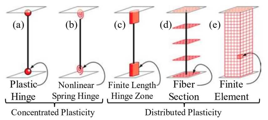
3.6. Modeling of Nonlinear Behavior
The nonlinear behavior of the structural members was represented using fiber-based plastic hinge models. A finite-length distributed-plasticity approach was adopted for columns and beams, and the plastic regions were modeled over finite plastic hinge lengths defined at the member ends. Fiber P-M2-M3 hinges accounting for the interaction of axial force and biaxial bending were used for columns and beams. For shear walls, Fiber P-M3 wall hinges based on a finite-element approach were defined and assigned to the meshed wall elements. The used plastic hinge idealizations are shown in Figure 7.
In the fiber sections, concrete behavior was represented using confined and unconfined concrete models defined in accordance with TBEC-2018, while reinforcement behavior was represented using a nonlinear stress–strain relationship. Fiber Hinge State results were used to evaluate member performance, and the maximum fiber states reached during the analyses were considered. The reliability of the adopted fiber-based modeling approach is supported by previous experimental validation studies. Van et al. [32] compared fiber-hinge numerical models of reinforced-concrete frames with cyclic test results and demonstrated that the approach could satisfactorily reproduce the nonlinear response, including peak strength and post-peak behavior. Nasr et al. [33] evaluated an ETABS fiber-hinge model for reinforced-concrete shear walls against thirteen experimentally tested wall specimens and reported good agreement between the numerical and experimental responses.
Figure 7.
Plastic hinge models [34].
3.7. Nonlinear Time-History Analysis
Ground-Motion Records and Spectral Characteristics
Two strong ground-motion records from the 6 February 2023 Kahramanmaraş earthquakes were selected to compare the behavior of the FD and FVD systems under substantially different levels of observed seismic demand while preserving the characteristics of the original recorded motions. Station records 4614 and 4612 were selected for the Pazarcık and Elbistan earthquakes, respectively. For the Pazarcık-4614 record, the peak ground accelerations in the E-W, N-S, and U-D components were 2.22 g, 2.21 g, and 1.99 g, respectively; for the Elbistan-4612 record, the corresponding values in the N-S, E-W, and U-D components were 0.65 g, 0.53 g, and 0.51 g. The strong-motion durations were approximately 60 s and 44 s, respectively [35]. The station locations and record characteristics are presented in Figure 8 and Table 3.
Figure 8.
Distances of the stations from the epicenters.
Table 3.
Characteristics of the selected ground-motion records.
The records were used in their original form without any scaling or spectral matching, thereby preserving their amplitude, frequency content, and time-dependent characteristics. The selected records were not intended to represent design ground motions spectrally compatible with the ZD site class assumed for the building site; rather, they were treated as observed strong-motion cases with different spectral and frequency characteristics. Therefore, the design spectrum developed for site class ZD was used only as a reference spectrum. The study does not aim to provide a code-based design verification or a statistical ranking of the FD and FVD systems, but rather to compare their relative seismic behavior under the same structural and preliminary design conditions when subjected to the selected real strong ground motions. Accordingly, the findings were evaluated within the scope of the two ground motions considered. Differences in the structural responses obtained under the Pazarcık and Elbistan records should not be attributed solely to differences in ground-motion amplitude, since their distinct spectral characteristics, strong-motion durations, and site conditions may also contribute to the observed response differences. The E-W, N-S, and U-D components of both records were applied simultaneously to the model, and the records were obtained from the AFAD Turkish Accelerometric Database and Analysis System [36]. The acceleration time histories and response spectra are presented in Figure 9.
Figure 9.
Acceleration time histories: (a) Elbistan-4612 and (b) Pazarcık-4614.
To evaluate the frequency content of the selected earthquake records and the seismic demands they impose on the structure, acceleration response spectra with 5% viscous damping were obtained. These spectra were compared with the design spectrum developed according to TBDY-2018 for local site class ZD and the DD-1 earthquake ground-motion level (Figure 10). Here, the DD-1 design spectrum was not used as a target spectrum for scaling the earthquake records; it was considered only as a reference for comparing the relative spectral demands of the unscaled records. DD-1 represents a very rare earthquake ground-motion level with a 2% probability of exceedance in 50 years and a return period of 2475 years.
Figure 10.
Spectral accelerations: horizontal (left) and vertical (right).
4. Results and Discussion
4.1. Natural Vibration Periods
The natural vibration periods of the models indicate that the dominant vibration mode occurred in the Y direction for all models (Table 4). Increasing the concrete compressive strength from 14 MPa to 30 MPa reduced the periods in all systems because of the associated increase in structural stiffness. As a result of this increase in concrete strength, Tx and Ty decreased by 8.0% and 8.2% in the UR models, 8.2% and 7.4% in the FD models, and 9.1% and 9.1% in the FVD models, respectively.
Table 4.
Natural vibration periods and percentage changes.
When the effect of damper type on the structural period was compared, the FD system provided a noticeable stiffness contribution. Relative to UR-14, Tx and Ty decreased by 16.6% and 15.9%, respectively, in the FD-14 model. Similarly, relative to UR-30, the corresponding reductions in the FD-30 model were 16.8% and 15.2%. In contrast, the effect of the FVD system on the structural periods was very limited. The periods of the UR-14 and FVD-14 models remained identical, whereas Tx and Ty in the FVD-30 model decreased by only 1.2% and 1.0%, respectively, relative to UR-30. This difference reflects the distinct operating mechanisms of the two systems: the FD modifies the dynamic characteristics of the structure through its friction-based hysteretic behavior, whereas the FVD primarily provides velocity-dependent energy dissipation and therefore has a limited effect on the natural periods.
4.2. Story Displacement
The variation in story displacements over the building height is shown in Figure 11. In all models, displacements increased with story elevation and reached their maximum values at roof level. Increasing the concrete strength from 14 MPa to 30 MPa reduced the roof displacements in all UR and FVD models, with reductions ranging from 28.9% to 50.8% under the Elbistan record and from 4.7% to 23.0% under the Pazarcık record. In contrast, the effect of increased concrete strength in the FD models was non-monotonic, with roof displacement increases of up to 7.3–10.1% observed in all cases except Elbistan-X. This result indicates that the effect of concrete strength on displacement response should be evaluated together with the damper mechanism and ground-motion characteristics.
Figure 11.
Maximum absolute story displacements: (a) Elbistan-4612 and (b) Pazarcık-4614.
Both damper systems substantially reduced story displacements relative to the UR models. At roof level, the reductions achieved by the FD system ranged from 20.6% to 63.9%, while those achieved by the FVD system ranged from 21.1% to 50.1%. The largest reduction, 63.9%, was obtained for the FD-14 model in the Elbistan-Y direction, whereas the FD and FVD systems produced more comparable results under the higher-demand Pazarcık record. In particular, in the Pazarcık-X direction, the reductions for C14 were 38.2% and 38.0% for FD and FVD, respectively, while for C30, they were 28.6% and 42.8%. Overall, the greater displacement reductions at the upper stories indicate that the effectiveness of both damper systems in controlling displacement becomes more pronounced toward the upper levels of the structure. The varying relative effectiveness of the FD and FVD systems indicates that displacement control is influenced by the interaction between their distinct friction-based and velocity-dependent mechanisms, the structural characteristics, and the ground-motion characteristics.
4.3. Story Drift
The maximum interstory drift ratios along the height of the models and the reductions achieved through retrofitting are presented in Figure 12. For both concrete strengths and earthquake records, the FD and FVD applications substantially reduced interstory drift demands. ASCE/SEI 7-22 [37] defines allowable story drifts depending on building characteristics and risk category. In this study, a 2% interstory drift ratio was used only as a reference level for comparative interpretation of the results and was not treated as an acceptance criterion for nonlinear structural performance.
Figure 12.
Maximum absolute interstory drift ratios: (a) Elbistan-4612 and (b) Pazarcık-4614.
Under the Y-direction component of the Pazarcık-4614 record, the 2.15% drift ratio obtained at Story 3 in the UR-14 model exceeded this reference level, whereas the FD-14 and FVD-14 applications reduced it to 0.97% and 1.23%, respectively. When the concrete strength was increased to 30 MPa, the maximum drift in the UR model decreased to 1.64%, while values of 1.05% and 0.94% were obtained for the FD and FVD applications, respectively. Thus, the drift demands in all retrofitted models remained below the 2% comparison level.
When retrofit effectiveness was evaluated by story, the FD system reduced drift by 37.2–65.6% and 28.3–54.9% under the Elbistan and Pazarcık records, respectively, for the 14 MPa models, while the corresponding reductions for the FVD system were 35.7–51.0% and 37.5–43.7%. For the 30 MPa models, the reductions ranged from 14.7% to 50.1% with FD and from 19.0% to 47.8% with FVD. These results show that both systems effectively limit interstory drifts, although their effectiveness depends on concrete strength, earthquake record, loading direction, and story level. At the lower concrete strength, FD provided greater reductions in some analysis cases, whereas in the 30 MPa models, particularly under the Pazarcık record, FVD provided more balanced drift control and greater reductions at most stories.
Increasing the concrete strength from 14 MPa to 30 MPa generally reduced drift demands in the UR models; however, this effect was more pronounced under the Elbistan record and more limited under the Pazarcık record, which generated higher structural demands. Moreover, the increase in concrete strength did not improve damper effectiveness in every retrofitted model. For the two concrete-strength conditions investigated, this finding indicates that the effectiveness of the FD and FVD systems depends not only on the strength of the primary structural system but also on the deformation level developed under seismic demand and on the energy dissipation mechanism of the dampers.
4.4. Story Accelerations
The variation in maximum absolute story accelerations obtained from the models is shown in Figure 13. Story accelerations generally increased with building height, and the highest values were obtained at Story 3. The Pazarcık-4614 record generated markedly higher acceleration demands than the Elbistan-4612 record in all models. This difference depends not only on the peak ground acceleration but also on the interaction between the frequency content of the ground-motion records and the dynamic characteristics of the structure. The literature also indicates that floor accelerations are strongly influenced by the relationship between the fundamental period and the frequency content of the ground motion.
Figure 13.
Maximum absolute story accelerations: (a) Elbistan-4612 and (b) Pazarcık-4614.
Increasing the concrete strength from 14 MPa to 30 MPa did not produce a unidirectional change in story accelerations. Under the Elbistan-4612 record, accelerations decreased particularly in the UR models, whereas under the Pazarcık-4614 record they increased at Story 3 in all models. Therefore, the reduction observed in displacement and interstory drift with increasing concrete strength cannot be generalized to story accelerations. This behavior may be attributed to the interaction between the changes in system stiffness and natural periods caused by increased concrete strength and the frequency content of the ground motion.
The effects of the FD and FVD systems on story accelerations also varied with earthquake record, concrete strength, and story level. Although both systems reduced acceleration demands in many cases, increases occurred in some analyses. Under the Pazarcık-4614 record, FVD-14 reduced story accelerations by 18.6–36.1% in the X direction and 28.7–43.9% in the Y direction, while the corresponding reductions for FVD-30 were 8.0–37.5% and 21.5–40.3%, respectively. In contrast, the FD system produced acceleration increases at some stories under the same record, reaching up to 19.6% for FD-14 and 16.3% for FD-30. These results indicate that FVD provided more consistent acceleration control over the building height, particularly under the high-demand Pazarcık record; however, the effect of supplemental damping on acceleration remains sensitive to the earthquake record and the dynamic characteristics of the structure. The acceleration increases observed in some FD cases may be associated with the more pronounced period shift introduced by the FD system, which alters the interaction between the structural dynamic characteristics and the frequency content of the ground motion. In contrast, the FVD provides velocity-dependent energy dissipation with only minor changes in the structural periods, which may account for its more consistent acceleration reductions under the Pazarcık record.
4.5. Story Forces and Base Shear Reactions
Story shear forces generally increased toward the lower stories; however, under the Pazarcık-4614 record, maximum values occurred at Story 2 in many models (Figure 14). This behavior may be associated with changes in the distribution of story shear forces resulting from the interaction among the dynamic characteristics of the earthquake record and the distributions of story mass, stiffness, and acceleration.
Figure 14.
Maximum absolute story shear forces: (a) Elbistan-4612 and (b) Pazarcık-4614.
The effect of increasing concrete strength on story shear demands was not unidirectional. Under the Elbistan-4612 record, story shears generally decreased in the UR model with 30 MPa concrete strength, whereas under the Pazarcık-4614 record, they increased, particularly in the X direction. In the retrofitted models, the effect of concrete strength also varied depending on the earthquake record, direction, and story level. This finding indicates that the differences in stiffness and natural periods between the two concrete-strength conditions can play an important role in the observed story shear demands.
When the damper systems were compared, FVD reduced story shear forces in all analysis cases, with reductions ranging from 2.2% to 47.8%. FD also provided substantial reductions in many cases, with the largest reduction of 54.4% obtained in the Pazarcık-Y direction; however, increases in story shears occurred in some cases. This behavior was particularly pronounced in the Pazarcık-X direction, where the Story 1 shear increased by 19.1% in the FD-14 model, while the Story 2 and Story 1 shears increased by 15.1% and 37.3%, respectively, in the FD-30 model. In contrast, FVD reduced shear demands at all stories under the same Pazarcık-X conditions. Thus, although FD produced larger maximum reductions in some analysis cases, FVD exhibited more consistent story-shear control across different concrete strengths and story levels.
The increases in story shear observed in some FD cases can be associated with the stiffness contribution and frictional force-transfer mechanism of the system. The FD models exhibited approximately 15–17% shorter fundamental periods than the corresponding UR models, indicating a noticeable modification of the structural dynamic characteristics. This period shift may alter the spectral demand imposed by a particular ground motion and may increase force demands even when deformation demands are reduced. In addition, the resisting forces developed by the friction dampers are transferred to the structural system. Therefore, the combined effects of stiffness modification, ground-motion frequency content, and damper-force transfer may result in increased story and base shear demands in some analysis cases.
The maximum base shear forces of the models are presented in Figure 15. Increasing the concrete compressive strength from 14 MPa to 30 MPa generally reduced base shear forces under the Elbistan-4612 record, whereas this effect was non-monotonic under the Pazarcık-4614 record. This result indicates that the influence of concrete strength on base shear demand varies depending on the earthquake record and retrofit system.
Figure 15.
Maximum absolute base shear forces: (a) Elbistan-4612 and (b) Pazarcık-4614.
At a concrete strength of 14 MPa, both damper systems reduced base shear forces in all analysis cases; reductions ranged from 12.4% to 85.8% for FD and from 43.7% to 63.1% for FVD. Under the Elbistan-4612 record, FD achieved greater reductions than FVD, whereas FVD exhibited more consistent behavior under the Pazarcık-4614 record. In particular, for the 30 MPa Pazarcık-X case, FD increased the base shear force by 30.9%, while FVD reduced it by 29.4%. In contrast, both systems were effective in the Pazarcık-Y direction, with reductions of 44.1% and 48.0% for FD and FVD, respectively. These results indicate that although FD can provide greater reductions in some analysis cases, FVD exhibits more consistent control of base shear forces, particularly under higher seismic demand. The contrasting base-shear responses are consistent with the mechanisms discussed above for story shear, indicating that deformation control and force-demand reduction do not necessarily occur proportionally.
4.6. Damper Response Demands
The device-level demands of the FD and FVD systems were evaluated using the step-by-step responses of all nonlinear link elements. For each model and ground-motion record, the axial force and axial deformation histories of the damper links at all three stories were examined. The axial velocity histories were obtained from the time derivative of the response using the 0.01 s analysis time interval. The absolute maximum values were first determined for each damper link and story, and the largest value among all links and stories was then reported as the peak demand for the corresponding model and ground motion. Therefore, the force, velocity, and deformation values reported in Table 5 do not necessarily occur simultaneously or in the same link element; each represents the maximum value of the corresponding response quantity over the complete analysis.
Table 5.
Peak axial response demands of the supplemental dampers under the investigated ground motions.
A pronounced ground-motion dependency is evident in the device demands. Compared with the Elbistan record, the Pazarcık record produced substantially greater axial velocity and deformation demands in both damper systems. Peak velocities increased by approximately one order of magnitude, while the peak deformation demands increased several-fold. This behavior is consistent with the considerably higher seismic demand of the Pazarcık record and demonstrates that damper stroke and velocity requirements may vary substantially even when the same device properties and arrangement are maintained.
The two damper mechanisms also exhibited distinct demand characteristics. Under the Elbistan record, the FD models developed larger peak axial forces but smaller deformation demands than the corresponding FVD models. Under the higher-demand Pazarcık record, the force demands of the two systems became more comparable, whereas the FVD models generally developed higher axial velocities and, particularly for the 14 MPa model, larger deformation demands. This difference is consistent with the velocity-dependent force generation of the FVD system and the friction-controlled hysteretic response of the FD system.
The influence of concrete strength on the device-level demands was not monotonic and depended on both the damper mechanism and the ground motion. Increasing the concrete strength from 14 to 30 MPa did not systematically reduce the peak damper force, velocity, or deformation.
4.7. Energy Components and Energy Dissipation
The time variation of the energy components is presented in Figure 16. For evaluating the energy dissipation performance of the supplemental dampers, the ETABS Link Hysteresis Energy output was used for the FD models, whereas the Link Damper Energy output was used for the FVD models. Both quantities were considered as supplemental damper energy (ED), while EH was reserved for the hysteretic energy dissipated by the structural members.
Figure 16.
Time variation of energy components.
The input energy (EI) was markedly higher under the Pazarcık-4614 record than under the Elbistan-4612 record. Increasing the concrete strength from 14 MPa to 30 MPa reduced EI in all models under the Elbistan-4612 record; under the Pazarcık-4614 record, it reduced EI in the UR and FVD models but increased it in the FD model.
For the FVD system, the energy dissipation ratio (ED/EI) ranged from 50.7% to 55.0% under the Elbistan record and from 64.9% to 66.5% under the Pazarcık record. For the FD system, the ED/EI ratio increased from 7.4–11.1% under the Elbistan record to 46.2–47.3% under the Pazarcık record. These results indicate that the contribution of both damping mechanisms to energy dissipation increased under higher seismic demand, with the increase being particularly pronounced for the FD system. Energy dissipation and equivalent damping provide complementary measures of response control, since equivalent damping relates the dissipated energy to a characteristic energy level of the system rather than to the dissipated energy alone [38]. Under the Pazarcık record, the effect of concrete strength on the energy dissipation ratios was limited, while the FVD system dissipated a larger proportion of the input energy through the dampers at both concrete strengths. This difference is consistent with the continuous velocity-dependent dissipation of the FVD, whereas FD energy dissipation becomes more pronounced as frictional sliding develops under higher seismic demand.
4.8. Structural Member Performance Levels
The nonlinear behavior of the structural members was evaluated using the Fiber Hinge State results obtained from ETABS analyses. Member damage states were classified according to the Immediate Occupancy (IO), Life Safety (LS), and Collapse Prevention (CP) acceptance criteria. Under the Elbistan-4612 earthquake record, beams, columns, and shear walls remained within the A-IO range in all models, whereas under the Pazarcık-4614 record, which produced higher damage demands, some members reached the IO-LS and LS-CP ranges (Figure 17).
Figure 17.
Plastic hinge states: (a1,a2) beams, (b1,b2) columns, and (c1,c2) shear walls; (a1–c1) models with a concrete strength of 14 MPa and (a2–c2) models with a concrete strength of 30 MPa.
Under the Pazarcık-4614 record, damage in the UR-14 model was concentrated particularly in the shear walls; 78.6% of the first-story shear walls reached the IO-LS range and 7.1% reached the LS-CP range. Increasing the concrete strength to 30 MPa substantially limited the damage distribution; however, some beams in the UR-30 model still reached the LS-CP range, while 28.6% of the first-story shear walls remained in the IO-LS range and 7.1% in the LS-CP range. Thus, the use of 30 MPa concrete alone did not completely eliminate advanced damage states in the investigated model.
The FD and FVD applications substantially limited the damage distribution at both concrete strengths, and no members reached the LS-CP range. This improvement was particularly evident in the FVD models. In the FVD-30 model, only 1.5% of the third-story beams and 7.1% of the first-story shear walls remained in the IO-LS range, while all other members remained within the A-IO range. Under cyclic loading, progressive damage is generally accompanied by stiffness degradation, reflecting the accumulation of nonlinear deformation in structural materials [39]. Accordingly, the more limited fiber-hinge damage observed in the damper-retrofitted models indicates reduced nonlinear demand on the primary structural members. Overall, increasing concrete strength reduced member damage, whereas the FD and FVD applications were more influential in preventing advanced damage, with FVD producing the most limited damage distribution.
4.9. Effective Equivalent Viscous Damping Ratios
Energy equivalence, in which the energy dissipated in one cycle is normalized by the maximum strain energy, provides the standard basis for equivalent viscous damping. The supplemental damping provided to the structure by friction dampers (FDs) and fluid viscous dampers (FVDs) was evaluated using an energy-based equivalent viscous damping approach. The initial damping ratio of the reinforced-concrete structure, ξ0, was assumed to be 5%. Because the supplemental dampers exhibited nonlinear behavior, their contribution to structural response was expressed in terms of an effective equivalent viscous damping ratio rather than a constant modal damping ratio.
The force-deformation responses of the dampers located in the same bays at each story were examined, and the high-amplitude hysteretic loops were verified to be temporally compatible (e.g., Pazarcık-4614, FD/FVD-14, Story 3, Figure 18). For each analysis case, the closed high-amplitude cycle exhibiting the largest deformation range of the reference damper link was selected for the equivalent damping calculation. The response of the reference link element was used to identify the corresponding cycle interval. For the representative cycle identified in this manner, the increase in Link Hysteresis Energy was considered for the FD models, whereas the increase in Link Damper Energy was considered for the FVD models. The damping calculation used the total energy dissipated by all dampers in the system rather than the energy of a single damper. The resulting values therefore represent an estimate of the effective equivalent viscous damping corresponding to the selected high-energy nonlinear response cycle, rather than the global modal damping ratio of the structure. The sensitivity of the calculated damping ratio to cycle selection was also examined using alternative closed high-amplitude cycles. Some cycle-to-cycle variation was observed; therefore, the calculated values are interpreted as cycle-specific effective damping estimates associated with high-amplitude nonlinear response rather than unique damping ratios representative of the entire earthquake response.
Figure 18.
Force–deformation hysteretic response of the dampers in the FD-14 and FVD-14 models under the Pazarcık ground motion.
The supplemental and effective equivalent viscous damping ratios were calculated using Equations (12) and (13), respectively.
ξeff = ξ0 + ξadd
Here, ΔEsupp denotes the supplemental energy dissipated by the entire damper system over the selected cycle, whereas ES,max denotes the maximum structural potential energy obtained from the ETABS step-by-step energy output within the same cycle. The selected cycle intervals, corresponding energy quantities, and calculated supplemental and effective equivalent viscous damping ratios for all analysis cases are summarized in Table 6. The calculated values represent effective equivalent viscous damping ratios corresponding to the selected high-amplitude cycle rather than constant modal damping ratios.
Table 6.
Cycle-specific energy parameters and calculated effective equivalent viscous damping ratios for the FD- and FVD-retrofitted models.
As shown in Table 6 and Figure 19, under the Pazarcık earthquake record, the effective equivalent viscous damping ratios were calculated as 8.50% and 7.97% for the FD-14 and FD-30 models, respectively. The corresponding values for the FVD-14 and FVD-30 models were 12.05% and 11.11%, respectively. Thus, under the higher seismic demand imposed by the Pazarcık record, the FVD system provided a greater effective equivalent damping contribution than the FD system for both concrete-strength conditions.
Figure 19.
Effective equivalent viscous damping ratios: (a) fc = 14 MPa and (b) fc = 30 MPa.
Under the Elbistan earthquake record, the effective equivalent viscous damping ratios were calculated as 6.15% and 6.00% for the FD-14 and FD-30 models, respectively, while the corresponding values for the FVD-14 and FVD-30 models were 9.09% and 8.50%. Although the effective damping contribution was lower than that obtained under the Pazarcık record, the FVD system again provided a greater contribution than the FD system for both concrete-strength conditions. Overall, the results indicate that the effective damping contribution of the nonlinear dampers depends on both the damper mechanism and the characteristics of the structural response under the selected ground motion. Accordingly, these values should be interpreted as cycle-specific effective equivalent viscous damping ratios rather than constant modal damping ratios.
5. Conclusions
In this study, the effects of friction dampers (FDs) and fluid viscous dampers (FVDs) on the seismic performance of a typical reinforced-concrete school building were compared considering concrete compressive strengths of 14 MPa and 30 MPa. Six models comprising unretrofitted (UR), FD-retrofitted, and FVD-retrofitted configurations were investigated through nonlinear time-history analyses using the Pazarcık (4614) and Elbistan (4612) ground-motion records from the 6 February 2023 Kahramanmaraş earthquakes. The main findings are summarized as follows:
- For the two concrete-strength conditions considered, the 30 MPa models exhibited higher structural stiffness and shorter natural vibration periods than the corresponding 14 MPa models. The FD system noticeably reduced the periods, whereas the effect of FVD on system stiffness and natural periods remained limited.
- Both damper systems substantially reduced displacement and interstory drift demands. Although the reduction ratios were more pronounced at the lower concrete strength, the absolute demands generally remained lower at the higher concrete strength. FD provided greater reductions in some cases, whereas FVD exhibited more balanced deformation control over the building height, particularly under higher seismic demand.
- For the two concrete-strength conditions considered, the differences in story acceleration, story shear, and base shear forces depended on the earthquake record, direction, and retrofit system. The interaction between system stiffness and natural period and the frequency content of the ground motion played an important role in the variation of these demands. Although the FD and FVD systems generally reduced these demands, increases were observed in some analysis cases. FVD reduced story shear forces in all analysis cases, whereas FD caused increases at some stories, particularly in the Pazarcık-X direction. For base shear forces, FD provided greater reductions under the Elbistan record, while FVD exhibited more consistent performance under the higher-demand Pazarcık record.
- Energy analyses showed that FVD dissipated 50.7–55.0% of the input energy under the Elbistan record and 64.9–66.5% under the Pazarcık record through the viscous mechanism. The supplemental damper energy ratio of FD was 7.4–11.1% and 46.2–47.3% under the Elbistan and Pazarcık records, respectively. The contribution of both systems to energy dissipation increased under the higher-demand Pazarcık record, while FVD reached higher energy dissipation ratios.
- The fiber-hinge results showed better member performance in the 30 MPa models than in the corresponding 14 MPa models, but damper use was more influential in limiting damage. No members reached the LS-CP range in the FD- and FVD-retrofitted models, and FVD generally produced a more limited damage distribution.
- The effective equivalent viscous damping ratios calculated for the selected high-amplitude response cycles were higher for the FVD system than for the FD system under both earthquake records and concrete-strength conditions. The calculated values ranged from 6.00% to 8.50% for the FD models and from 8.50% to 12.05% for the FVD models. Higher effective damping ratios were generally obtained under the Pazarcık record, indicating that the supplemental damping contribution varies with the structural response and seismic demand. These values should therefore be interpreted as cycle-specific effective damping estimates rather than constant modal damping ratios representative of the entire earthquake response.
Overall, under the structural configuration, damper parameters, and ground motions considered in this study, both FD and FVD systems substantially improved seismic performance. While FD provided greater reductions in some response parameters, FVD exhibited more balanced and consistent behavior when deformation, force, energy dissipation, and member performance were considered together, particularly under the high-demand Pazarcık record. These observations represent the relative behavior of the two systems within the present case study rather than a general performance ranking. The results demonstrate that damper mechanism and seismic demand should be considered together with concrete strength when evaluating seismic retrofitting strategies for existing reinforced-concrete structures.
The findings of this study should be interpreted within the scope of the adopted analysis framework. Two real ground-motion records from the 6 February 2023 Kahramanmaraş earthquakes were used in their original form without scaling. Since the records have different site conditions and VS30 values, the observed response differences may reflect not only the seismic demand but also the characteristics of the selected ground motions and local site conditions. The FD and FVD systems were evaluated using a common force-based preliminary sizing approach rather than separate optimization, providing a controlled basis for comparing the two damping mechanisms. In addition, the damper connections were idealized to focus on the global seismic response, and local connection effects were not explicitly considered. Finally, because the evaluations were performed for a single three-story reinforced-concrete school building with two concrete-strength conditions and a fixed damper arrangement, the observed response trends should be interpreted within the investigated structural conditions and should not be directly generalized to substantially different structural systems or damper-layout characteristics. These limitations provide clear directions for further research. Future studies may extend the present comparative framework by considering a broader range of building heights and structural characteristics, alternative damper arrangements, a larger set of ground-motion records, device-specific optimization, and more detailed modeling of damper connections to evaluate their influence on the seismic response of FD- and FVD-retrofitted structures.
Author Contributions
Conceptualization, M.U., T.Y.A., M.Y. and K.E.A.; Methodology, M.U., T.Y.A. and M.Y.; Validation, M.U., T.Y.A. and M.Y.; Investigation, M.U., T.Y.A., M.Y. and K.E.A.; Data curation, T.Y.A.; Writing—original draft, M.U., T.Y.A., M.Y. and K.E.A.; Writing—review and editing, M.U., T.Y.A., M.Y. and K.E.A.; Visualization, M.U., T.Y.A., M.Y. and K.E.A.; Supervision, M.U., T.Y.A., M.Y. and K.E.A. All authors have read and agreed to the published version of the manuscript.
Funding
This study was supported by the Scientific Research Projects Coordination Unit of Firat University. Project Number: MF.25.57.
Data Availability Statement
The original contributions presented in this study are included in the article. Further inquiries can be directed to the corresponding author.
Conflicts of Interest
Among the authors, Muhammed Ulucan, Kürşat Esat Alyamaç, and Musa Yetkin serve as consultants at SEBIZA Technology Limited Company. The remaining authors declare that the research was conducted in the absence of any commercial or financial relationships that could be construed as a potential conflict of interest.
References
- Sahin, H.; Alyamac, K.E.; Durucan, A.R.; Demirel, B.; Ulas Acikgenc, M.; Bildik, A.T.; Durucan, C.; Demir, T.; Ulucan, M.; Demirbas, N. 24 January 2020 Mw 6.8 Sivrice Earthquake Elazığ Region Structural Damages Investigation and Evaluation Report; Construction and Concrete Application and Research Center: Elazığ, Türkiye, 2020. [Google Scholar] [CrossRef]
- Ulucan, M.; Alyamac, K.E. A holistic assessment of the use of emerging recycled concrete aggregates after a destructive earthquake: Mechanical, economic and environmental. Waste Manag. 2022, 146, 53–65. [Google Scholar] [CrossRef] [Scilit] [PubMed]
- Dedeoglu, I.O.; Yetkin, M.; Tunc, G.; Ozbulut, O.E. Evaluating earthquake-induced damage in Dogansehir, Malatya after 2023 Kahramanmaras earthquake sequence: Geotechnical and structural perspectives. J. Build. Eng. 2025, 104, 112266. [Google Scholar] [CrossRef] [Scilit]
- Dedeoğlu, İ.Ö.; Yetkin, M.; Calayır, Y. 24 January 2020 Sivrice-Elazığ earthquake: Assessment of seismic characteristics of earthquake, earthquake territory and structural performance of reinforced concrete structures. Sak. Univ. J. Sci. 2022, 26, 892–907. [Google Scholar] [CrossRef] [Scilit]
- Gani, E.; Dedeoglu, I.O.; Sari, A.; Ozbulut, O.E.; Yetkin, M. Directional seismic performance of reinforced concrete buildings under near-fault ground motions. Bull. Earthq. Eng. 2026. [Google Scholar] [CrossRef] [Scilit]
- Yön, B.; Dedeoğlu, İ.Ö.; Yetkin, M.; Erkek, H.; Calayır, Y. Evaluation of the seismic response of reinforced concrete buildings in the light of lessons learned from the February 6, 2023, Kahramanmaraş, Türkiye earthquake sequences. Nat. Hazards 2025, 121, 873–909. [Google Scholar] [CrossRef] [Scilit]
- Altiok, T.Y. Structural performance analysis of a retrofitted school building collapsed in Kahramanmaras earthquakes and evaluation of applied retrofitting methods. Bull. Earthq. Eng. 2025, 23, 4943–4974. [Google Scholar] [CrossRef] [Scilit]
- Yıldız, M.G. Design of Seismic Retrofitting Using Innovative Techniques: A Case Study on a School Building. Master’s Thesis, Boğaziçi University, Istanbul, Türkiye, 2025. [Google Scholar]
- Kaleybar, R.S.; Tehrani, P. Effects of using different arrangements and types of viscous dampers on seismic performance of intermediate steel moment frames in comparison with different passive dampers. Structures 2021, 33, 3382–3396. [Google Scholar] [CrossRef] [Scilit]
- Şevik, M.; Altiok, T.Y.; Demir, A. Investigation of the effect of damper location and slip load calculation on the behavior of a RC structure. Earthq. Struct. 2023, 24, 365–375. [Google Scholar] [CrossRef]
- Suk, R.; Demir, A.; Altintas, G.; Altiok, T.Y. Proposal for a novel technological damper system (TDS) for the retrofit of reinforced concrete frame structures. Structures 2024, 60, 105878. [Google Scholar] [CrossRef] [Scilit]
- Suk, R.; Demir, A.; Altiok, T.Y.; Altintas, G. Advancing earthquake resistance: Hybrid retrofitting of RC frames with FRP and TDS. Structures 2024, 66, 106851. [Google Scholar] [CrossRef] [Scilit]
- Armaly, M.; Damerji, H.; Hallal, J.; Fakih, M. Effectiveness of friction dampers on the seismic behavior of high rise building VS shear wall system. Eng. Rep. 2019, 1, e12075. [Google Scholar] [CrossRef] [Scilit]
- Grossi, E.; Aprile, A.; Zerbin, M.; Livieri, P. Preliminary experimental tests of a novel friction damper for seismic retrofit of RC precast structures. Eng. Struct. 2024, 305, 117718. [Google Scholar] [CrossRef] [Scilit]
- Yan, L.; Zhang, C. Hysteretic performance of square rotational friction damper. Adv. Struct. Eng. 2025, 28, 1843–1857. [Google Scholar] [CrossRef] [Scilit]
- Kiadarbandsari, S.; Nezamabadi, M.F.; Abbasi, H.; Vayeghan, F.Y. Analytical and experimental investigation of steel friction dampers and horizontal brake pads in chevron frames under cyclic loads. Structures 2022, 40, 256–272. [Google Scholar] [CrossRef] [Scilit]
- Bruschi, E.; Zoccolini, L.; Cattaneo, S.; Quaglini, V. Experimental characterization, modeling, and numerical evaluation of a novel friction damper for the seismic upgrade of existing buildings. Materials 2023, 16, 1933. [Google Scholar] [CrossRef] [Scilit] [PubMed]
- Ma, P.; Yuan, S. Seismic retrofitting of RC frames using viscous dampers: Numerical simulation and nonlinear response analysis. Infrastructures 2025, 10, 235. [Google Scholar] [CrossRef] [Scilit]
- Das, A.; Bandyopadhyay, D. Study on seismic base shear and deformation of regular and irregular buildings using different properties of fluid viscous dampers. Structures 2025, 76, 108925. [Google Scholar] [CrossRef] [Scilit]
- Çalım, F.; Güllü, A.; Yüksel, E. A comprehensive state-of-the-art review on energy-based procedures in earthquake-resistant structural design. Arch. Civ. Mech. Eng. 2026, 26, 45. [Google Scholar] [CrossRef] [Scilit]
- Symans, M.D.; Charney, F.A.; Whittaker, A.S.; Constantinou, M.C.; Kircher, C.A.; Johnson, M.W.; McNamara, R.J. Energy dissipation systems for seismic applications: Current practice and recent developments. J. Struct. Eng. 2008, 134, 3–21. [Google Scholar] [CrossRef] [Scilit]
- Soong, T.T.; Spencer, B.F., Jr. Supplemental energy dissipation: State-of-the-art and state-of-the-practice. Eng. Struct. 2002, 24, 243–259. [Google Scholar] [CrossRef] [Scilit]
- Xu, W.; Wang, Y.; Guo, H.; Du, D.; Wang, S. Theoretical and experimental investigation on the seismic performance of a novel variable-damping viscous fluid damper. J. Build. Eng. 2022, 53, 104537. [Google Scholar] [CrossRef] [Scilit]
- Dong, S.; Pan, W.; Ye, L.; Wang, J. Design of displacement-based viscous damper damping structures. Sci. Rep. 2025, 15, 11742. [Google Scholar] [CrossRef] [Scilit] [PubMed]
- Gao, W.; Lu, X. Supplemental damping and energy dissipation of structural systems installed with viscous dampers considering connection stiffness. Structures 2024, 70, 107629. [Google Scholar] [CrossRef] [Scilit]
- Dong, B.; Sause, R.; Ricles, J.M. Modeling of nonlinear viscous damper response for analysis and design of earthquake-resistant building structures. Bull. Earthq. Eng. 2022, 20, 1841–1864. [Google Scholar] [CrossRef] [Scilit]
- Mavroeidakos, P.; Katsimpini, P.; Papagiannopoulos, G. Effect of viscous dampers with variable capacity on the response of steel buildings. Vibration 2025, 8, 11. [Google Scholar] [CrossRef] [Scilit]
- AFAD. Turkish Building Earthquake Code (TBEC-2018); Disaster and Emergency Management Presidency (AFAD): Ankara, Türkiye, 2018.
- Gong, Z.; Ma, P. A comparative study of metallic mild steel dampers and fluid viscous dampers in reinforced concrete structures based on nonlinear time history analysis. Infrastructures 2026, 11, 318. [Google Scholar] [CrossRef] [Scilit]
- Taylor Devices Inc. Fluid Viscous Dampers: General Guidelines for Engineers; Taylor Devices Inc.: North Tonawanda, NY, USA, 2019. [Google Scholar]
- Pall Dynamics Ltd. Pall Friction Dampers. Available online: https://www.palldynamics.com (accessed on 6 September 2026).
- Van, T.C.; Lau, T.L.; Mohamed Nazri, F. Macro-modeling approach incorporating fiber plastic hinge for reinforced concrete frames with masonry infill. Eng. Struct. 2022, 251, 113421. [Google Scholar] [CrossRef] [Scilit]
- Nasr, O.; Moustafa, A.; Ghallab, A.H. Flexural behaviour of RC shear wall using enhanced finite element model. Sci. Rep. 2026, 16, 15491. [Google Scholar] [CrossRef] [Scilit] [PubMed]
- Deierlein, G.G.; Reinhorn, A.M.; Willford, M.R. Nonlinear Structural Analysis for Seismic Design: A Guide for Practicing Engineers; NEHRP Seismic Design Technical Brief No. 4, NIST GCR 10-917-5; National Institute of Standards and Technology: Gaithersburg, MD, USA, 2010.
- Nasery, M.M.; Sadid, M.S.; Sadid, F.Z. Post-earthquake assessment and strengthening of the historical Elbistan Museum located at the epicenter of the Mw 7.6 Kahramanmaraş earthquake. Bull. Earthq. Eng. 2026, 24, 5993–6050. [Google Scholar] [CrossRef] [Scilit]
- AFAD. Turkish Accelerometric Database and Analysis System (TADAS); Disaster and Emergency Management Presidency: Ankara, Türkiye, 2026. Available online: https://tadas.afad.gov.tr (accessed on 3 October 2026).
- ASCE/SEI 7-22; Minimum Design Loads and Associated Criteria for Buildings and Other Structures. American Society of Civil Engineers: Reston, VA, USA, 2022. [Google Scholar] [CrossRef] [Scilit]
- Wang, C.; Zhao, W.; Ma, Z. X-ray CT and SHPB characterization of energy dissipation and impact-equivalent damping in steel-fiber-reinforced recycled cementitious composites. Constr. Build. Mater. 2026, 542, 148039. [Google Scholar] [CrossRef] [Scilit]
- Wang, C.; Liu, J.; Dai, Y.; Ma, Z. Elucidate CO2 enhancement on multiscale mechanical behavior and stiffness degradation of fiber-reinforced recycled aggregate concrete under cyclic loading. J. Build. Eng. 2025, 111, 113298. [Google Scholar] [CrossRef] [Scilit]
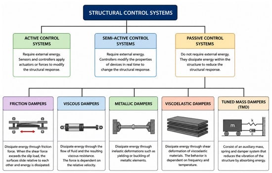
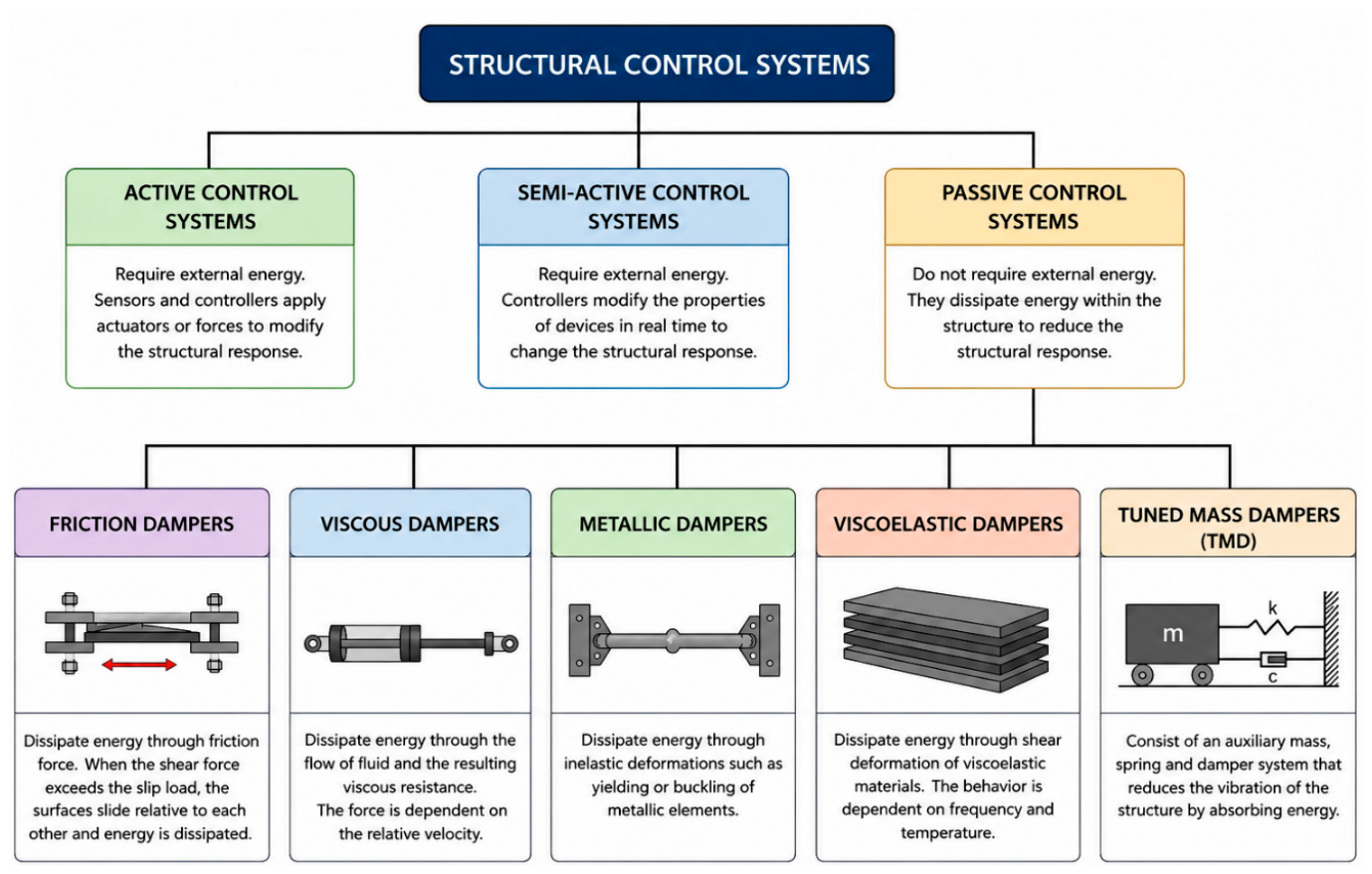
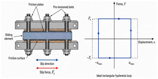
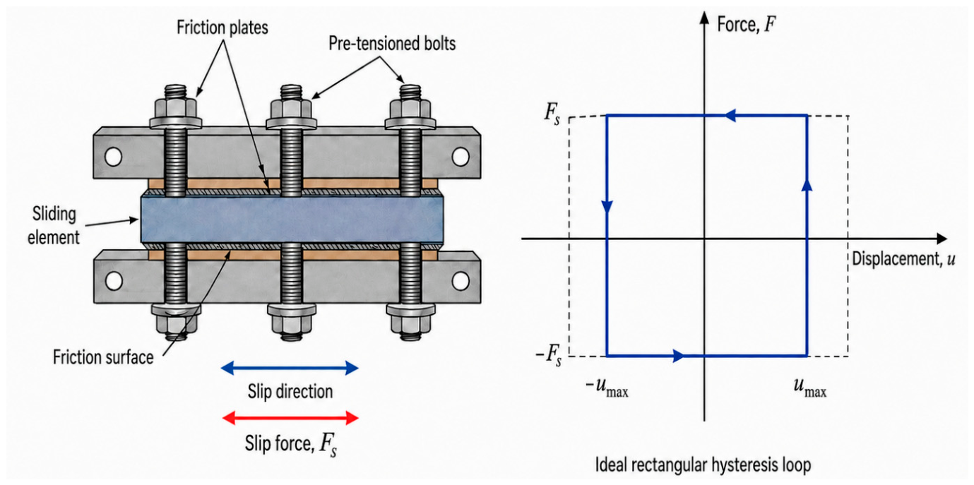
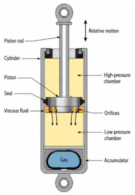
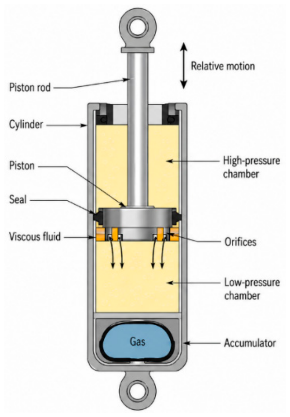
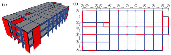
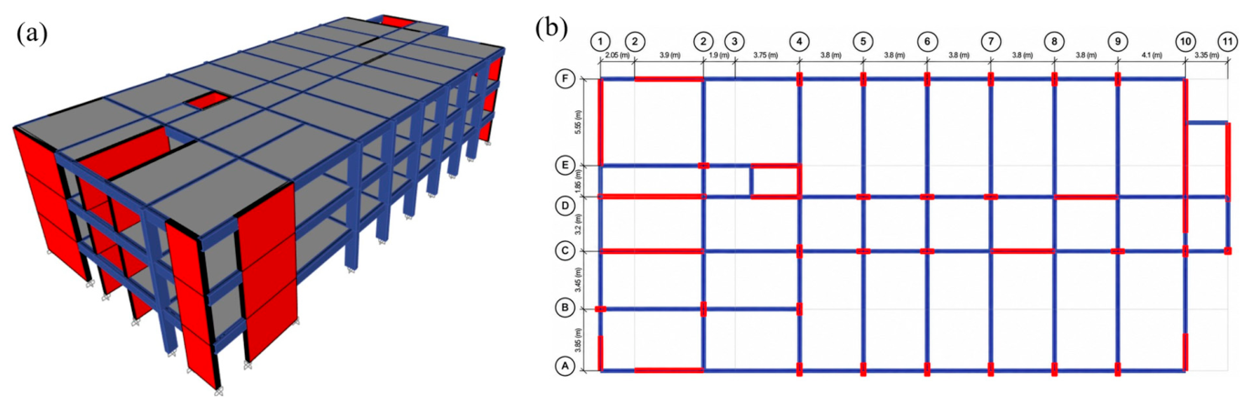
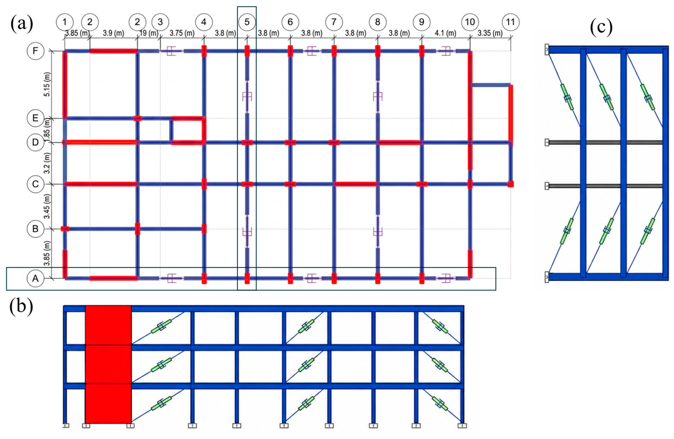
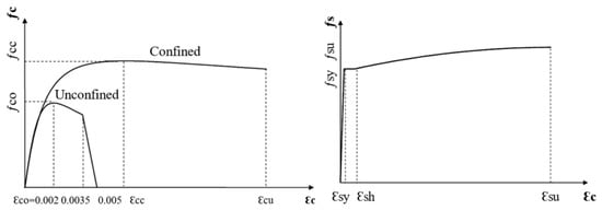
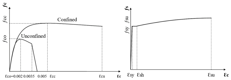
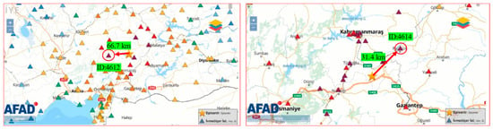
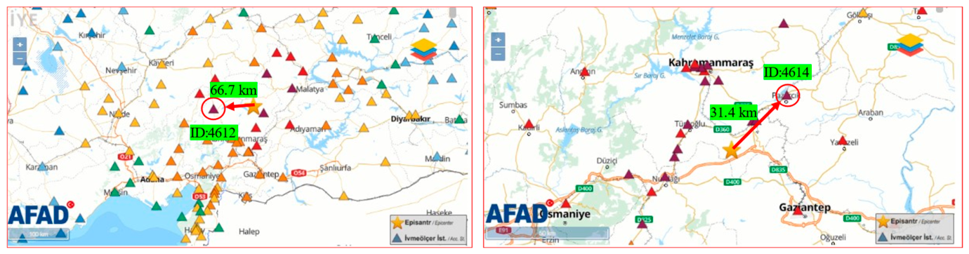
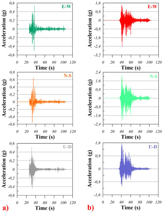
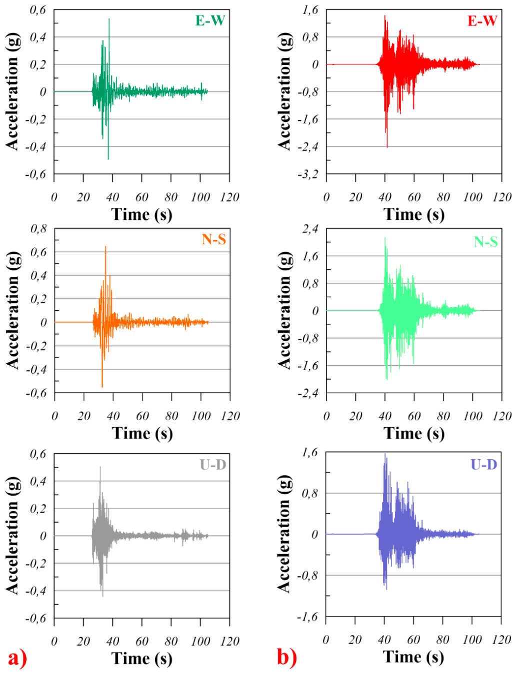
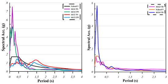
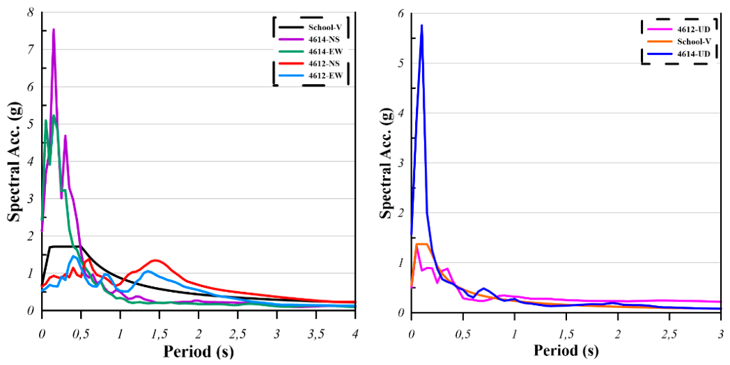
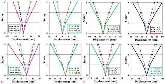
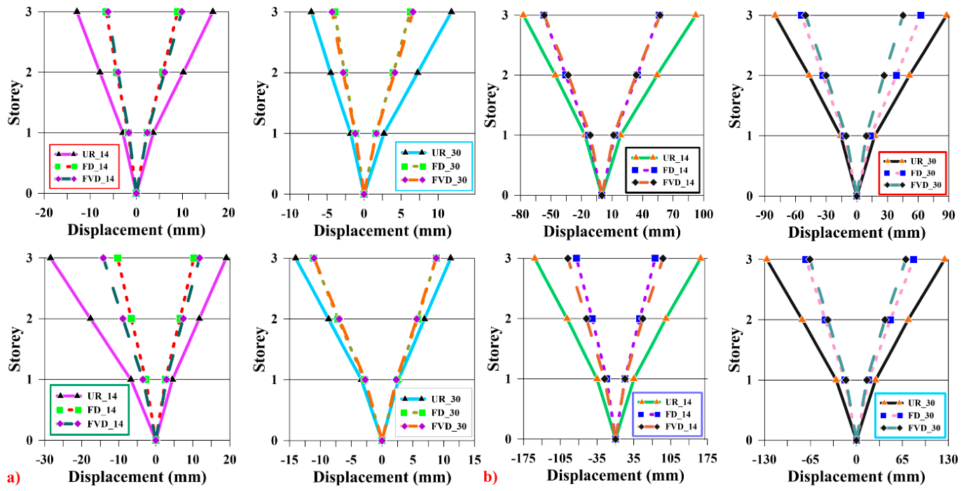
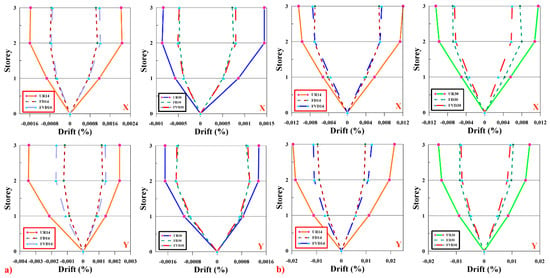
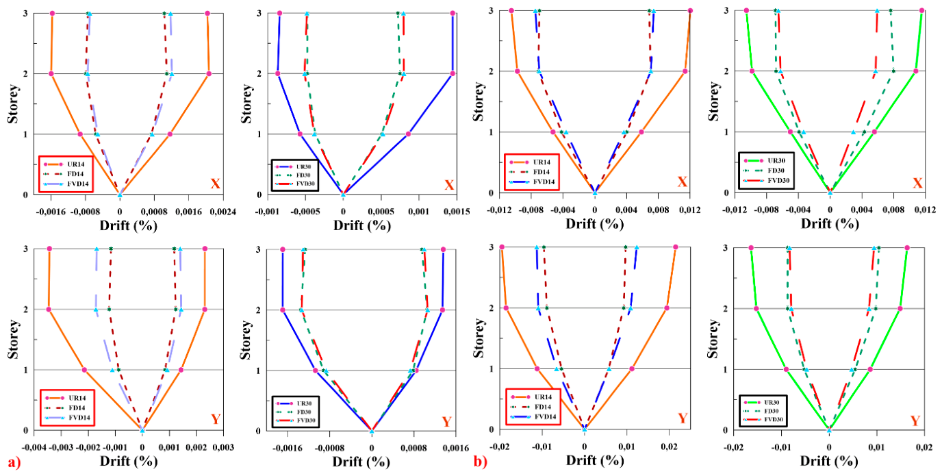
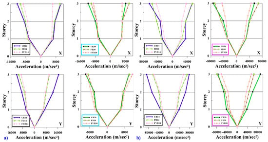
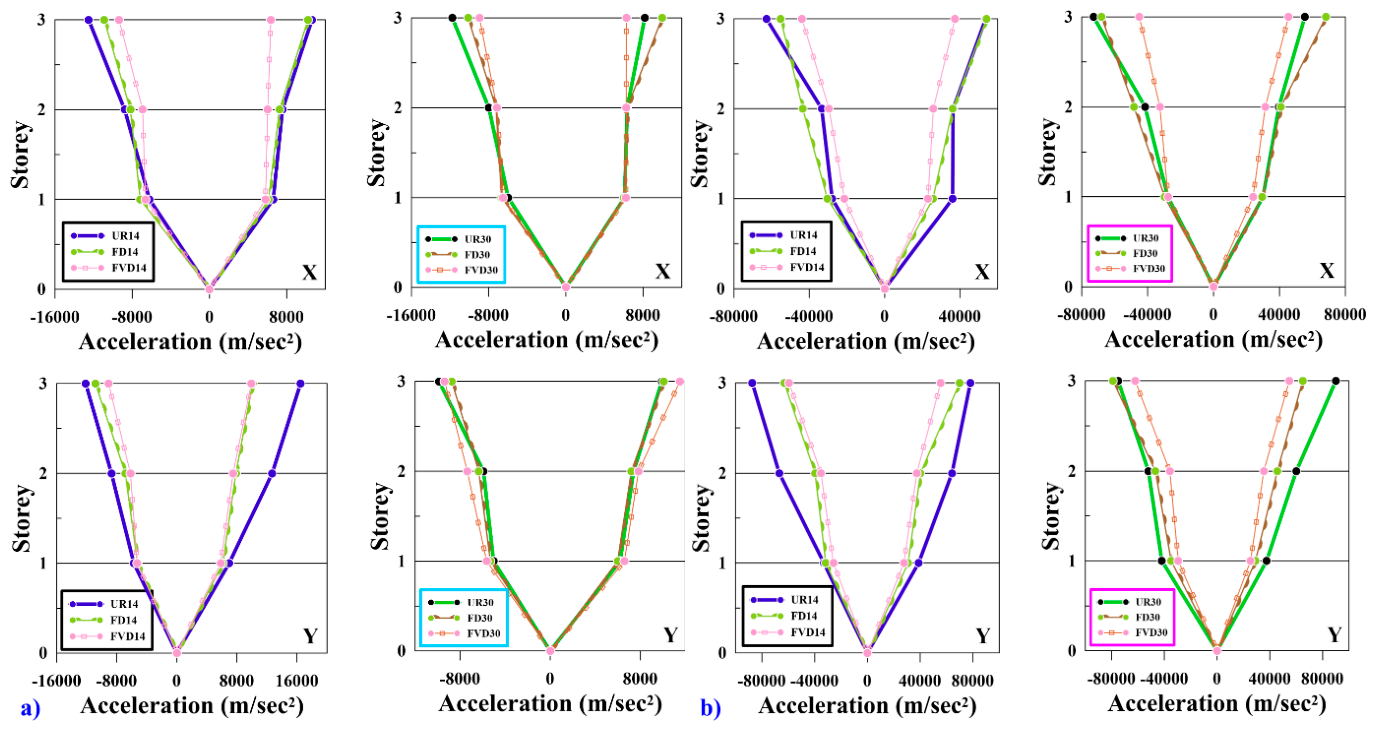
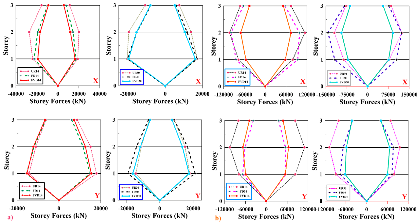
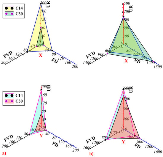
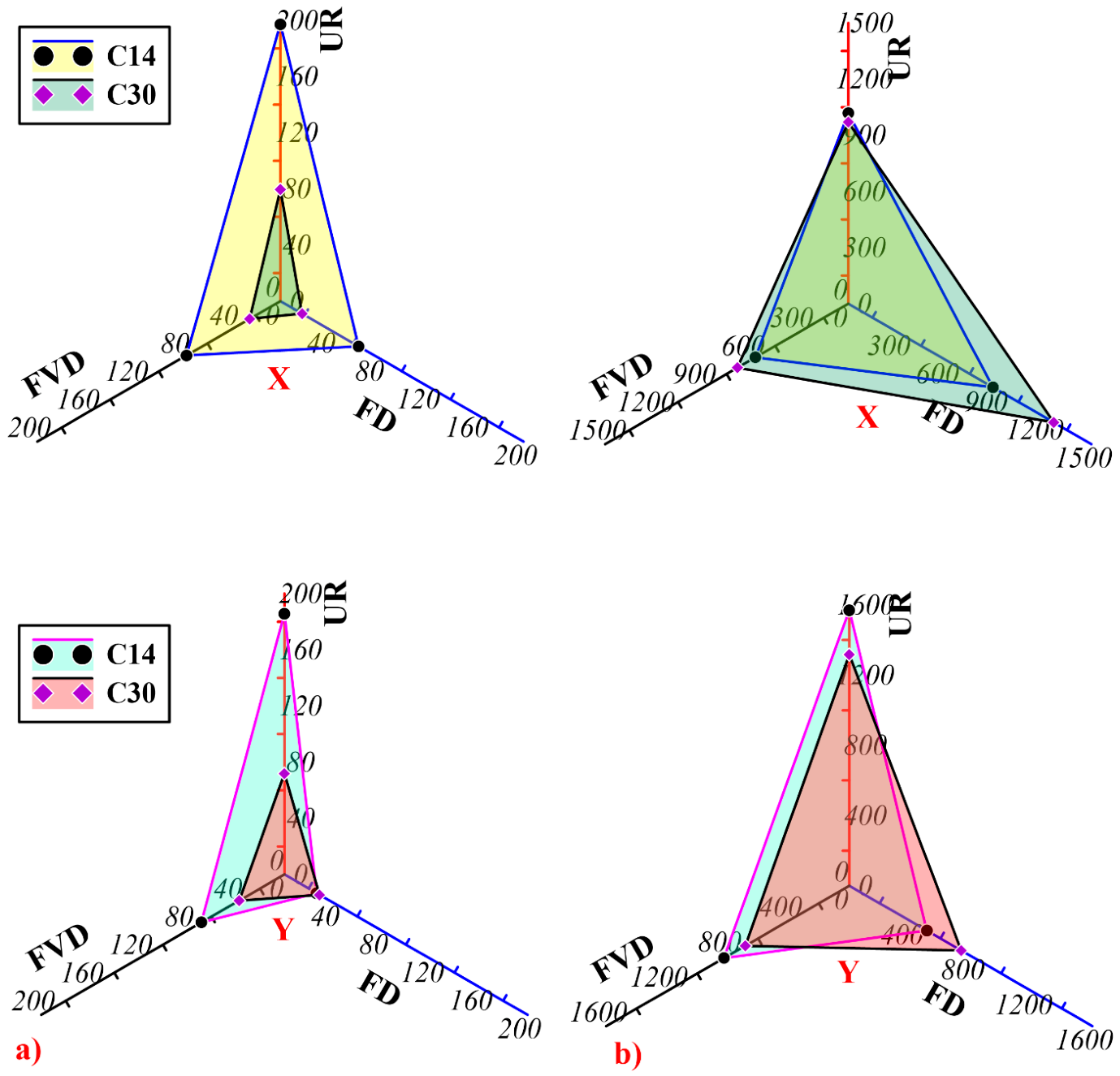
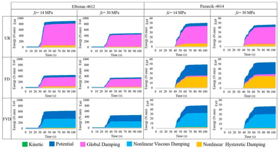
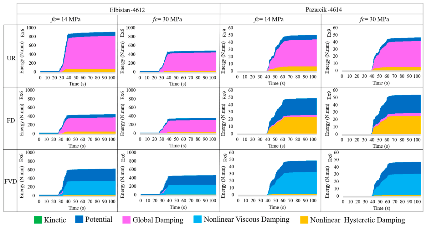
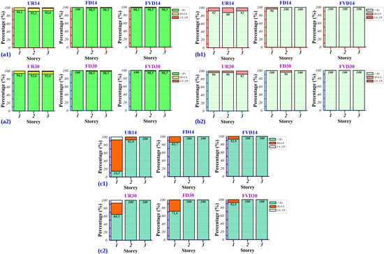
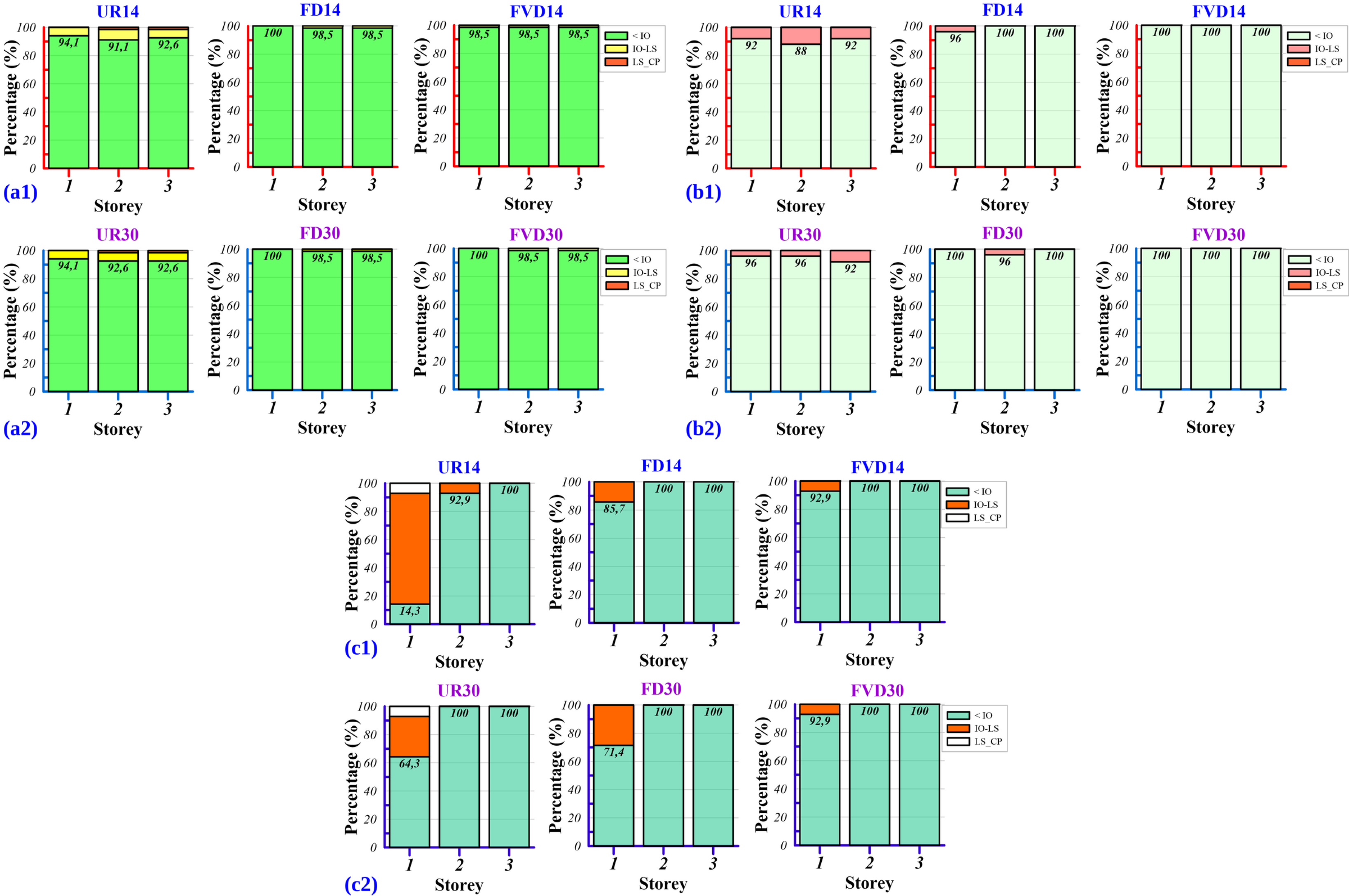
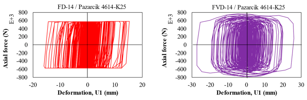
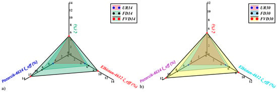
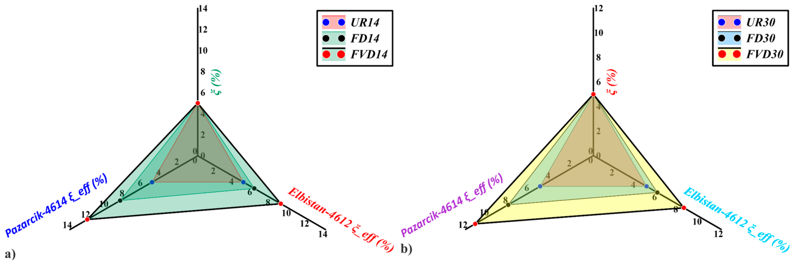

Disclaimer/Publisher’s Note: The statements, opinions and data contained in all publications are solely those of the individual author(s) and contributor(s) and not of MDPI and/or the editor(s). MDPI and/or the editor(s) disclaim responsibility for any injury to people or property resulting from any ideas, methods, instructions or products referred to in the content. |
© 2026 by the authors. Licensee MDPI, Basel, Switzerland. This article is an open access article distributed under the terms and conditions of the Creative Commons Attribution (CC BY) license.