


Abstract
This paper presents a multi-parametric optimization framework for trapezoidal stone gravity retaining walls subjected to static and pseudo-static seismic loading. The wall is treated as a no-tension gravity structure, and the base width, top width, and embedment depth are optimized by minimizing the wall self-weight. The objective function is constrained by overturning, eccentricity, sliding, and bearing-capacity requirements, as well as by lower geometric bounds. The analytical formulation is implemented directly in an optimization model and includes Coulomb-type active earth pressure, Mononobe–Okabe seismic pressure, mobilized passive resistance, wall inertia, and bearing capacity. Two foundation scenarios are considered: Scenario A, with identical foundation and retained soil properties, and Scenario B, with competent foundation soil. The parameter grid combines five retained-soil heights, six soil friction angles, four passive-resistance mobilization factors and four seismic accelerations, evaluated for two foundation scenarios and three loading branches (static and two opposite-sign vertical seismic branches), producing 2160 optimized designs. The results reveal distinct mechanically controlled design regimes. In Scenario A, low friction angles are governed mainly by bearing capacity and sliding, whereas eccentricity dominates as friction increases. In Scenario B, sliding and bearing cease to govern, and the optimum is controlled predominantly by eccentricity, with overturning appearing in a limited low-wall domain. The positive and negative vertical seismic branches produce different design demands, with the negative branch becoming progressively more critical as seismic intensity increases. The optimized base-width-to-height ratio further shows that weak foundation conditions can lead to markedly more massive wall geometries, whereas stronger foundation soil enables substantially more compact solutions.
1. Introduction
Gravity retaining walls are among the oldest and mechanically simplest earth-retaining systems and continue to be used in transportation infrastructure, slope stabilization, terracing, river engineering, reconstruction work, and landscape applications. Their stability is provided predominantly by self-weight rather than by flexural resistance. Consequently, wall geometry is directly coupled with sliding resistance, overturning stability, bearing capacity, and the distribution of contact stresses beneath the base. Dry-stone retaining walls are constructed from individual stone blocks without mortar and rely primarily on self-weight, friction, and mechanical interlocking. The stone–concrete wall considered in this study consists predominantly of stone blocks bonded with concrete, whereas conventional reinforced-concrete retaining walls consist of concrete with steel reinforcement provided to resist tensile and flexural stresses. In stone and masonry gravity walls, tensile resistance across joints generally cannot be relied upon to the same extent as in reinforced concrete structures, which makes the position of the base resultant and the maintenance of predominantly compressive contact particularly important [1]. The internal shear resistance of mortared stone masonry is provided by friction and adhesion at the stone–mortar interfaces, while surface roughness and mechanical interlocking can further enhance shear-force transfer between individual stones [2]. The geotechnical design of such structures is generally governed by the principles of Eurocode 7, while the seismic design of retaining structures is additionally covered by Eurocode 8, Part 5 [3,4]. Eurocode 8 explicitly treats earth-retaining structures and soil–structure interaction under seismic actions and permits pseudo-static approaches for retaining structures.
The seismic response of gravity retaining walls is more complex than their static response because earthquake loading affects both the lateral earth-pressure demand and the stabilizing contribution of the wall itself. The conventional Mononobe–Okabe approach represents earthquake effects through horizontal and vertical pseudo-static coefficients and remains one of the principal analytical tools for seismic earth-pressure evaluation [5].
Seismic performance is also strongly affected by the interaction between the retaining system, foundation conditions, and surrounding soil [6,7]. Al-Taie and Ahmed [8] reviewed the observed performance of earth-retaining structures during past earthquakes and emphasized that actual seismic behavior depends on several interacting geotechnical and structural factors. Recent studies have further examined seismic retaining-wall behavior, including experimental and numerical observations of dynamic earth pressures, displacement-dependent seismic active earth pressure, and active and passive earth-pressure solutions for constrained backfill conditions [6,7,9]. Parameter optimization under seismic loading has also been investigated for other retaining-wall systems [10]. Mylonakis et al. [11] developed a stress-plasticity solution incorporating wall roughness, geometry and horizontal and vertical seismic acceleration, while Conti et al. [12] modelled coupled wall–soil dynamics. Subsequent studies examined sliding and rocking [13], permanent displacements across different geometries and soils [14], and links between critical acceleration, plastic mechanisms and performance-based design [15]. Tsantilas et al. [16] compared dynamic earth pressures with classical pseudo-static solutions under varying excitation and interface conditions. These studies provide context for interpreting the present results as optimized pseudo-static design states.
Because gravity walls rely directly on their geometry to generate stabilizing resistance, their design is particularly suitable for optimization. Conventional design is generally iterative: a preliminary cross-section is selected, external stability and foundation resistance are checked, and the wall dimensions are subsequently modified until all requirements are satisfied. Optimization offers a more systematic alternative by treating the geometrical dimensions as design variables and satisfying the relevant geotechnical constraints simultaneously. Talatahari et al. [17] applied the Charged System Search algorithm to the seismic optimization of gravity retaining walls and used the Mononobe–Okabe method to evaluate pseudo-static earth pressures. Talatahari and Sheikholeslami [18] subsequently extended this approach to least-cost optimization of gravity and reinforced-concrete retaining walls for different backfill conditions. These studies demonstrated the effectiveness of metaheuristic procedures for finding economical retaining-wall configurations [19]; however, their principal emphasis was on optimization performance and the final optimum rather than on systematic identification of transitions between the governing geotechnical mechanisms.
Other computational approaches have further expanded retaining-wall optimization [20,21]. Xu et al. [22] combined an artificial neural network with ant-colony optimization to investigate retaining walls under dynamic loading, considering parameters such as wall dimensions, soil density, friction angle, and stone density. Pham and Do [23] recently applied swarm-intelligence algorithms to the optimization of a stone masonry gravity retaining wall with explicit consideration of the dimensions of its stone base. Their objective incorporated construction cost, while geometrical, material, overall-stability, and foundation constraints were enforced. These studies illustrate the increasing use of artificial intelligence and population-based optimization in retaining-wall engineering.
A broader multi-parametric perspective was introduced by Varga et al. [24], who analyzed 567 combinations of input parameters for optimally designed gravity retaining walls and demonstrated that wall height, soil friction angle, interface conditions, backfill geometry, and surcharge significantly affect the optimum configuration. This approach shifted the focus from a single optimum toward understanding how optimal designs evolve over a broader parameter space. Varga and Jelušič [25] subsequently extended gravity-wall optimization into a reliability framework by combining deterministic optimization with a prescribed probability of failure. These investigations demonstrated that optimization can be used not only to reduce construction cost but also to study parameter sensitivity and reliability. Nevertheless, their principal focus was not the systematic transition between static and opposite vertical seismic loading branches or between different geotechnical governing mechanisms.
Recent studies have also increasingly addressed the mechanics and design of stone and dry-stone retaining walls. Distinct-element analyses by Powrie et al. [26] distinguished toppling and bulging and identified the influence of foundation compressibility and joint deterioration. Full-scale investigations by Villemus et al. [27] and Mundell et al. [28] examined the transition from global wall behavior to internal deformation and failure. Colas et al. [29] subsequently compared full-scale observations with yield-design predictions. For granite dry-masonry walls, Alejano et al. [30,31] investigated relevant material parameters and compared analytical assessments with back-analyses and numerical models. Savalle et al. [32] developed a static and pseudo-static design framework for dry-stone retaining walls according to Eurocodes 7 and 8 and identified the geometrical parameters that are particularly important under seismic loading. More recently, Ding et al. [33] investigated the optimization of dry-stone wall shape using complementary physical, analytical, and numerical approaches. Their work identified overturning and sliding as relevant failure mechanisms and showed that wall inclination can be optimized with respect to stability and the amount of masonry used. Singh et al. [34], using a three-dimensional discrete-element model, investigated stress development and deformation of gravity retaining walls under static loading at the grain scale, providing further insight into the development of the active state and wall–soil interaction. Together, these studies demonstrate growing interest in the mechanics and optimization of stone retaining structures, but they address predominantly specific wall shapes, individual failure mechanisms, or selected static or seismic design situations.
Another important modelling issue is the contribution of passive resistance in front of the embedded portion of a retaining wall. Classical earth-pressure theories describe limiting active and passive states, whereas the resistance actually mobilized in practice depends on wall displacement [35,36]. Fan et al. [37] developed a displacement-dependent formulation for passive earth pressure and showed that the passive state develops progressively with wall movement. This distinction is particularly relevant in optimization, because automatically assigning the full theoretical passive resistance could produce unrealistically favorable solutions. A parametric representation of partial passive-resistance mobilization is therefore useful when deformation-dependent soil response is not explicitly included.
Despite these advances, an important research gap remains. Previous studies have addressed seismic gravity-wall optimization, dry-stone wall geometry, reliability, machine-learning-based optimization, discrete-element response, and individual failure mechanisms. However, comparatively little attention has been given to systematically mapping how the governing design mechanism of an optimized stone gravity wall changes over a combined geotechnical and seismic parameter space. In particular, the coupled effects of retained-soil friction angle, foundation-soil quality, wall height, seismic intensity, the sign of the vertical seismic acceleration, and partial passive-resistance mobilization have not been comprehensively evaluated within a single optimization framework.
The present study addresses this gap by developing a multi-parametric minimum-weight optimization framework for trapezoidal stone gravity retaining walls under static and pseudo-static seismic loading. The wall base width B, top width Bz, and embedment depth d are treated as continuous design variables, while overturning, eccentricity, sliding, bearing capacity, and geometrical requirements are imposed simultaneously as optimization constraints. Two contrasting geotechnical configurations are investigated: Scenario A, in which the foundation soil has the same friction angle as the retained soil, and Scenario B, in which the wall rests on competent foundation soil. The adopted study comprises 2160 optimized designs covering five retained heights, six retained-soil friction angles, four passive-resistance mobilization factors, and four seismic intensities.
A distinctive aspect of the study is that the seismic condition is separated into two independent branches, EARTHQUAKE+ and EARTHQUAKE−, obtained by reversing the sign of the vertical seismic coefficient while maintaining the same horizontal coefficient. This enables the influence of vertical seismic acceleration to be evaluated explicitly and makes it possible to identify the acceleration level at which seismic loading becomes more demanding than the static condition and which direction of the vertical component governs the optimum. Passive resistance is also treated parametrically through λp. Importantly, these values represent upper bounds on passive-resistance mobilization, while the passive force actually used in equilibrium is limited to that mechanically required to balance the horizontal driving action.
The principal novelty of the proposed approach lies not only in determining a minimum-weight wall, but in extending previous static and reliability-based optimization studies [24,25] to a combined static–seismic framework. The complete optimization database is used to identify transitions between bearing-capacity-, sliding-, eccentricity-, overturning-, and geometry-controlled design regimes, to determine how these transitions depend on foundation conditions and seismic intensity, and to quantify the relative importance of the EARTHQUAKE+ and EARTHQUAKE− branches. In addition, the influence of the relative magnitudes of the vertical and horizontal seismic components is assessed through a dedicated sensitivity analysis. The optimized base-width-to-height ratio B/H is further evaluated as an indicator of wall massiveness and practical geometric efficiency. The resulting framework thus links optimized geometry and material demand to the underlying soil-mechanical failure mechanism over a combined geotechnical and seismic parameter space.
2. Materials and Methods
2.1. Objectives and Framework of the Study
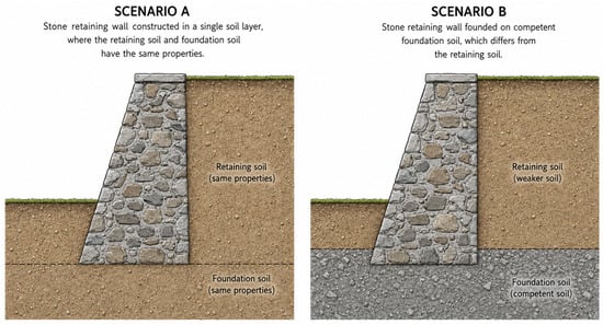
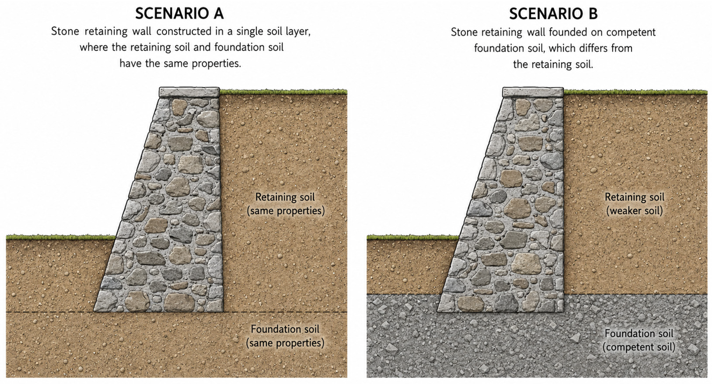
The aim of this study is to investigate how different geotechnical and seismic conditions influence the minimum-weight design and governing mechanisms of stone gravity retaining walls within a Eurocode-based framework. In this paper, two geotechnical scenarios are considered (see Figure 1):
Figure 1.
Geotechnical configurations considered in Scenarios A and B.
- Scenario A: A stone retaining wall is constructed in a single soil layer where the retained soil and the foundation soil have the same properties.
- Scenario B: A stone retaining wall is founded on competent foundation soil, which differs from the retained soil.
These two scenarios reflect a common geotechnical design situation in which a site investigation is first used to identify the depth and quality of the bearing stratum. Based on these conditions, the wall may either be founded within the existing weaker formation or the excavation may be extended to reach a more competent foundation layer. The two scenarios were therefore selected to represent these contrasting foundation choices and to isolate the influence of foundation soil quality on the optimized wall geometry and governing failure mechanism.
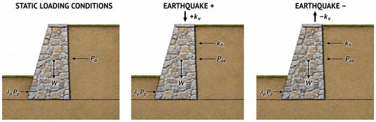
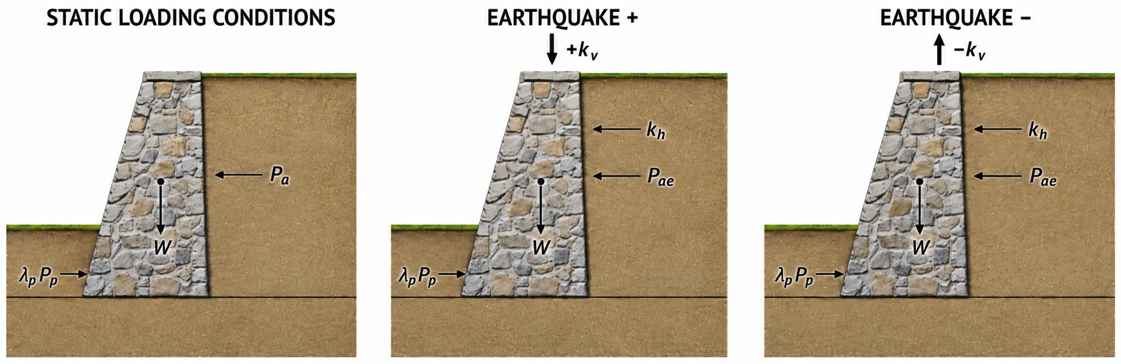
Three loading conditions are analyzed: STATIC and two pseudo-static seismic conditions with opposite signs of the vertical seismic coefficient (see Figure 2). The influence of different levels of passive resistance mobilization is also investigated.
Figure 2.
Loading conditions considered in the analysis: static loading and the two pseudo-static seismic branches, EARTHQUAKE+ (kv > 0, downward vertical inertia action) and EARTHQUAKE− (kv < 0, upward vertical inertia action). Pa denotes the static active earth pressure, Pae the seismic active earth pressure, Pp the passive earth pressure, λp the passive-resistance mobilization factor, kh and kv the horizontal and vertical pseudo-static inertia coefficients, respectively, and W the wall self-weight.
In the present sign convention, kv denotes the vertical pseudo-static inertia coefficient. A positive value, kv > 0, represents a downward pseudo-static inertia action, acting in the same direction as gravity, and therefore increases the effective wall weight according to Gseis = G(1 + kv). Conversely, kv < 0 represents an upward pseudo-static inertia action and reduces the effective wall weight.
2.2. Optimization Model
An optimization model was developed to minimize the weight of the stone retaining wall. The constrained nonlinear optimization was performed using the Generalized Reduced Gradient (GRG) Nonlinear algorithm implemented in Microsoft Excel Solver. Automatic scaling was enabled, the constraint precision was set to 10−6, and the convergence tolerance was 10−4. Forward numerical derivatives were used, while the Multistart option was activated. The following assumptions were applied in the optimization model and in the calculations:
- Two different geotechnical scenarios were considered:
- ∘
- Scenario A: the retaining soil and the foundation soil have the same properties;
- ∘
- Scenario B: competent foundation soil differs from the retained soil.
- Three different loading conditions:
- ∘
- Static loading conditions;
- ∘
- Pseudo-static loading conditions with downward vertical inertia action (EARTHQUAKE+);
- ∘
- Pseudo-static loading conditions with upward vertical inertia action (EARTHQUAKE−).
The proposed optimization model includes input data (constants), variables, parameters, the objective function of the structure, structural analysis, and dimensioning constraints. The main input data, variables, and parameters are listed in Table 1. The objective function of the stone retaining wall weight G (kN/m) is defined by Equation (1):
G = γwall·(B + Bz)/2·(Hs + d)
Table 1.
Input data, continuous design variables, and calculated quantities used in the optimization model.
In Equation (1), γwall is the unit weight of the stone wall and Hs is the height of retained soil above the excavation level. Bz is the wall top width, B is the wall base width, and d is the wall embedment depth; these are defined as continuous design variables.
The weight objective function defined by Equation (1) is subject to the geotechnical and geometrical constraints summarized in Table 2, formulated in accordance with Eurocode 7 and Eurocode 8 [3,4].
Table 2.
Geotechnical analysis and structural constraints.
Three loading conditions are considered separately: STATIC, EARTHQUAKE+, and EARTHQUAKE−. The STATIC condition represents the conventional gravitational loading state, whereas EARTHQUAKE+ and EARTHQUAKE− represent pseudo-static seismic loading with opposite signs of the vertical seismic coefficient kv. This distinction is important because the vertical seismic component affects not only the wall self-weight but also the seismic earth-pressure coefficients and consequently the overall equilibrium of the wall.
Equations (2)–(5) define the four principal utilization ratios used as optimization constraints: overall stability (Ustab), sliding (Uslide), eccentricity (Uexc), and bearing capacity (Ubearing). A feasible solution requires all utilization ratios to be less than or equal to unity. The eccentricity condition reflects the no-tension assumption adopted for the stone–concrete gravity wall by limiting the base resultant to the middle third of the foundation width. Equations (6)–(8) additionally impose the geometrical constraints on the wall base width B, top width Bz, and embedment depth d.
Equations (9)–(16) define the basic geometry, wall weight, wall–soil interface friction angles, and seismic coefficients. These quantities provide the common basis for the three loading conditions. In the STATIC analysis, the seismic coefficients are not activated. For the seismic analyses, the horizontal coefficient kh is combined with either the positive or the negative value of kv. Thus, the two earthquake cases differ only in the direction of the vertical seismic component, while the wall geometry, soil parameters, and horizontal seismic coefficient remain unchanged.
Equations (17)–(23) define the active and passive earth-pressure coefficients. The STATIC analysis uses the static coefficients Ka and Kp, whereas EARTHQUAKE+ and EARTHQUAKE− use the corresponding seismic coefficients Kae and Kpe. The seismic inertia angle used in the Mononobe–Okabe formulation depends on both kh and kv. Consequently, reversing the sign of the vertical seismic coefficient produces different seismic active and passive pressures for EARTHQUAKE+ and EARTHQUAKE−. The seismic increment of the active coefficient is evaluated separately for the retained-soil self-weight and for the surcharge. According to the Mononobe–Okabe admissibility condition, φ′ − β − θ must be satisfied to ensure a real-valued seismic earth-pressure coefficient. For the horizontal backfill considered in this study β = 0, this reduces to θ ≤ φ′. This condition was satisfied for all parameter combinations investigated.
Equations (24)–(41) transform the earth-pressure coefficients into the corresponding forces, horizontal and vertical components, and lever arms. The static active thrust is separated into the contribution from the uniformly distributed surcharge P1 and the contribution from the retained-soil self-weight P2. These static components are present in all three loading conditions. In the two seismic cases, additional seismic thrusts are introduced together with the horizontal inertia force of the wall. The effective wall weight is also modified by the vertical seismic component. Therefore, EARTHQUAKE+ and EARTHQUAKE− differ simultaneously in the seismic earth pressure and in the effective gravitational action of the wall.
Passive resistance in front of the embedded part of the wall is also evaluated separately for static and seismic loading. For STATIC, the available passive resistance is based on Kp, while the seismic coefficient Kpe is used for EARTHQUAKE+ and EARTHQUAKE−. The available resistance is reduced by the passive mobilization factor λp and is additionally limited to the amount actually required to balance the driving horizontal actions. This prevents the model from using a passive resistance greater than that which needs to be mobilized for equilibrium. The upper value λp = 0.30 was adopted as a conservative parametric limit, consistent with the restricted contribution of passive resistance adopted in Eurocode 8 foundation-sliding provisions.
Equations (42)–(55) define the stabilizing and destabilizing moments and the design vertical action at the wall base. In the STATIC condition, equilibrium is governed by the wall self-weight, static active earth pressure, and mobilized passive resistance. In EARTHQUAKE+ and EARTHQUAKE−, the equilibrium additionally includes the horizontal wall inertia force, the seismic increments of active earth pressure, and the effective wall weight modified by kv. The positive and negative seismic branches are therefore evaluated independently, since changing the sign of kv propagates through the seismic earth-pressure coefficients, wall weight, passive resistance, and moment equilibrium.
Equations (56)–(59) determine the location of the resultant at the wall base, the corresponding eccentricity, and the effective base width. The mathematical expressions are common to all loading conditions, but the resulting values differ because the acting forces and moments are evaluated independently for STATIC, EARTHQUAKE+, and EARTHQUAKE−. This directly affects the no-tension verification and the distribution of contact stresses below the wall.
Equations (60)–(62) define the sliding verification. For STATIC, the driving horizontal action is determined from the static active earth-pressure components and the mobilized passive resistance. For the seismic cases, the horizontal wall inertia force and seismic earth-pressure increments are additionally included. At the same time, the available frictional sliding resistance depends on the vertical design action and is therefore also affected by the sign of kv. Consequently, the vertical seismic component influences both the driving and resisting terms of the sliding verification.
Finally, Equations (63)–(73) define the base contact stresses and bearing-capacity verification. The same bearing-capacity formulation is used for all three loading conditions, but the calculation employs the loading-condition-specific values of VEd, HEd, and eccentricity eB. The model therefore accounts for the influence of the seismic loading not only on earth pressures and sliding but also on the position of the base resultant, effective contact width, contact pressure, and bearing resistance.
Overall, the formulation comprises three parallel verification branches. STATIC represents the reference gravitational condition, while EARTHQUAKE+ and EARTHQUAKE− represent two distinct seismic conditions obtained by changing the sign of the vertical seismic coefficient. This separation allows the optimization procedure to determine not only the minimum-weight wall geometry but also which loading condition and which failure mechanism—overturning, sliding, eccentricity, or bearing capacity—governs the optimum design. This is directly aligned with the main objective of the study, namely, to identify transitions between the governing static and seismic design situations.
3. Multi-Parametric Optimization
A multi-parametric optimization was performed to systematically investigate the influence of the main geometrical, geotechnical, and seismic parameters on the optimal design of a stone gravity retaining wall. Instead of analyzing only individual wall configurations, a predefined parameter grid was considered, and an independent optimization was carried out for each combination of input parameters. In each optimization run, the wall self-weight G was minimized by varying the three continuous design variables: the base width B, the top width Bz, and the embedment depth d. The optimum solution was required to satisfy the stability, eccentricity, sliding and bearing-capacity constraints, together with the prescribed geometrical limits.
Two geotechnical scenarios were considered. In Scenario A, the foundation soil was assumed to have the same friction angle as the retained soil, i.e., φfd = φ. In Scenario B, a higher-strength foundation soil with a constant friction angle φfd = 45° was assumed, while the friction angle of the retained soil was varied. This separation enables the influence of foundation-soil quality on the optimal wall geometry and governing failure mechanism to be evaluated independently.
The multi-parametric optimization was performed for the following parameter values:
- five retained-soil heights, Hs = 2, 3, 4, 5 and 6 m;
- six effective friction angles of the retained soil, φ = 20°, 25°, 30°, 35°, 40° and 45°;
- four passive-resistance mobilization factors, λp = 0, 0.1, 0.2 and 0.3;
- four design ground-acceleration ratios for the seismic analyses, α = ag/g = 0.10, 0.15, 0.20 and 0.25;
- two geotechnical scenarios, Scenario A and Scenario B.
The uniformly distributed surcharge was kept constant at q = 0 kPa in the present parametric study. The wall top width and embedment depth were constrained by Bz ≥ 0.70 m and d ≥ 1.00 m, respectively, while the geometrical condition B ≥ Bz was also imposed. The values of λp represent upper bounds on passive-resistance mobilization; the actual passive force used in each optimization is limited to that required by horizontal equilibrium, as described in Section 2.2.
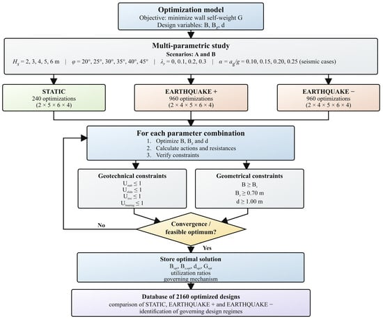
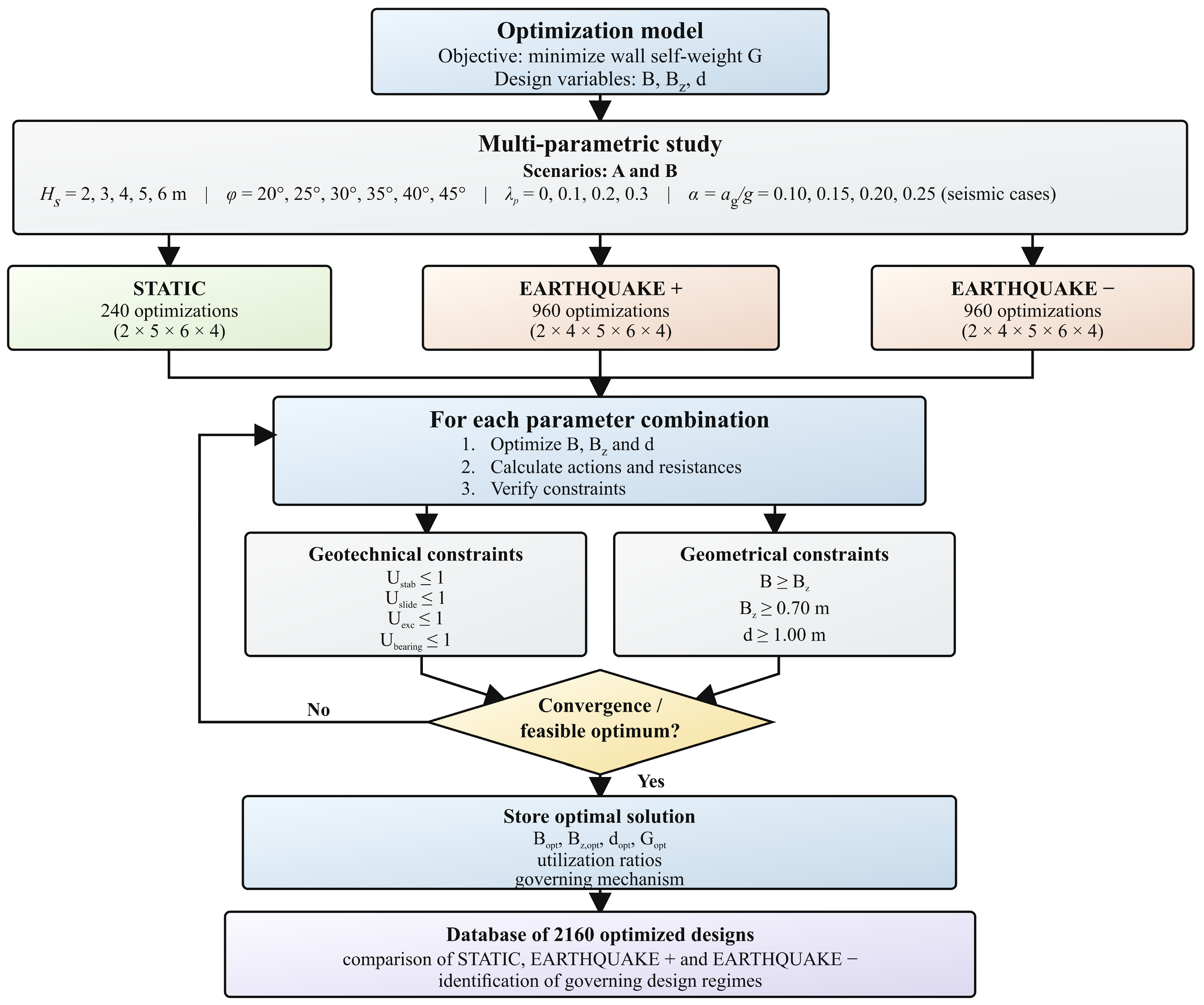
For every combination of the above parameters, three loading conditions were distinguished: STATIC, EARTHQUAKE+, and EARTHQUAKE−. The static analysis does not depend on the seismic acceleration parameter and was therefore performed for 5 × 6 × 4 = 120 parameter combinations for each geotechnical scenario. Considering both scenarios (A and B), this resulted in 240 static optimizations.
For the seismic analyses, four values of α were considered. Consequently, 4 × 5 × 6 × 4 = 480 optimizations were performed for each seismic branch and each geotechnical scenario. Thus, 960 optimizations were performed for EARTHQUAKE+ and 960 for EARTHQUAKE−. Together with the static cases, the complete multi-parametric analysis comprised 2160 individual optimization runs.
The two seismic branches were treated as independent loading conditions. For a given value of α, the same horizontal seismic coefficient kh was used, whereas the sign of the vertical coefficient kv was reversed between EARTHQUAKE+ and EARTHQUAKE−. Consequently, the two seismic analyses generally produce different seismic active and passive earth-pressure coefficients, effective wall weights, sliding resistances and base resultants. Treating both branches independently therefore makes it possible to determine which direction of the vertical seismic action governs the optimum wall design. This distinction is also one of the principal objectives of the study.
Each of the 2160 optimization runs produced an optimal set of B, Bz, and d, together with the corresponding minimum wall self-weight Gopt. In addition, the utilization ratios for overall stability, eccentricity, sliding and bearing capacity were stored. A constraint was classified as active when its utilization ratio was within the adopted numerical tolerance of unity. The resulting database therefore enables not only comparison of the minimum-weight wall geometries but also identification of transitions between overturning, eccentricity, sliding, and bearing-capacity-controlled design regimes over the investigated parameter space.
The adopted multi-parametric procedure thus provides a systematic basis for comparing the two geotechnical scenarios and the three loading conditions. In particular, it enables direct evaluation of how Hs, φ, λp and seismic intensity influence the optimum wall geometry and weight, and whether the governing design condition changes from STATIC to EARTHQUAKE+ or EARTHQUAKE− as the seismic intensity increases.
The overall multi-parametric optimization procedure is illustrated in Figure 3. For each combination of the predefined input parameters, the wall geometry is optimized independently for the corresponding loading condition. The optimal geometry, minimum wall weight, and utilization ratios are then stored in a common database, which forms the basis for the subsequent comparison of the static and seismic design regimes.
Figure 3.
Flowchart of the multi-parametric optimization procedure for the stone gravity retaining wall.
The principal input data and parameter values adopted in the multi-parametric optimization are summarized in Table 3. The retained-soil height Hs, friction angle φ, passive-resistance mobilization factor λp, and design ground acceleration ratio α were varied systematically, whereas the remaining parameters were kept constant. In Scenario A, the foundation and retained soils have the same friction angle, while in Scenario B the foundation-soil friction angle was fixed at 45°. For the persistent design situation, Eurocode 7 Design Approach 2 (“A1” + “M1” + “R2”) was adopted, whereas unit partial factors were used for the seismic design situation in accordance with Eurocode 8, as indicated in Table 3. For the seismic cases, the horizontal seismic coefficient was calculated as kh = αS/r, while the two seismic branches were obtained by considering positive and negative vertical seismic coefficients, kv = ±0.5kh. The value r = 2.0 corresponds to a free gravity wall capable of accommodating permanent displacement according to EN 1998-5 [4], while kv = ±0.5kh represents the case avg/ag > 0.6. A fully rough wall–soil interface was idealized by adopting δ = φ and δfd = φfd, consistent with the strongly rough character of the stone surface and the documented influence of surface roughness on soil–structure interface friction [38]. This represents the limiting case of a very rough interface, for which δ may approach φ. In addition to the baseline value kv/kh = 0.5, the complete seismic parametric analysis was repeated for kv/kh = 0.33 and kv/kh = 0 to assess the sensitivity of the optimized response to the relative magnitude of the vertical seismic component.
Table 3.
Input data used in the multi-parametric optimization.
4. Results and Discussion
4.1. Overall Optimization Results
The multi-parametric analysis yielded 2160 optimal designs, comprising 240 static solutions and 1920 pseudo-static seismic solutions. For each parameter combination, the wall base width B, top width Bz, and embedment depth d were optimized by minimizing the wall self-weight G, while satisfying the stability, eccentricity, sliding, bearing-capacity, and geometrical constraints.
Table 4 summarizes the overall response of the optimization model. A clear difference is observed between the two geotechnical scenarios. In Scenario A, where the retained and foundation soils have the same friction angle, substantially larger wall widths and self-weights are required, particularly for low values of φ. The optimized top width Bz generally remains at its lower bound of 0.70 m. Only 125 of the 2160 solutions, approximately 5.8%, require Bz > 0.70 m. Similarly, the embedment depth remains at dmin = 1.0 m in most cases; only 183 solutions, approximately 8.5%, require a deeper embedment. Consequently, the base width B is the principal geometrical variable through which the optimizer accommodates changes in the geotechnical and seismic demand.
Table 4.
Summary statistics of the optimized wall geometry and material demand for Scenarios A and B under STATIC, EARTHQUAKE+, and EARTHQUAKE− loading.
To compare walls of different heights, the normalized material index (see Equation (74)) was used:
ηG = G/(γwall·H2)
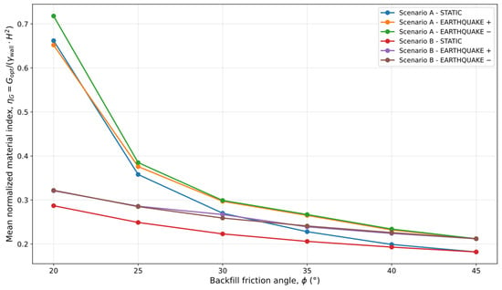
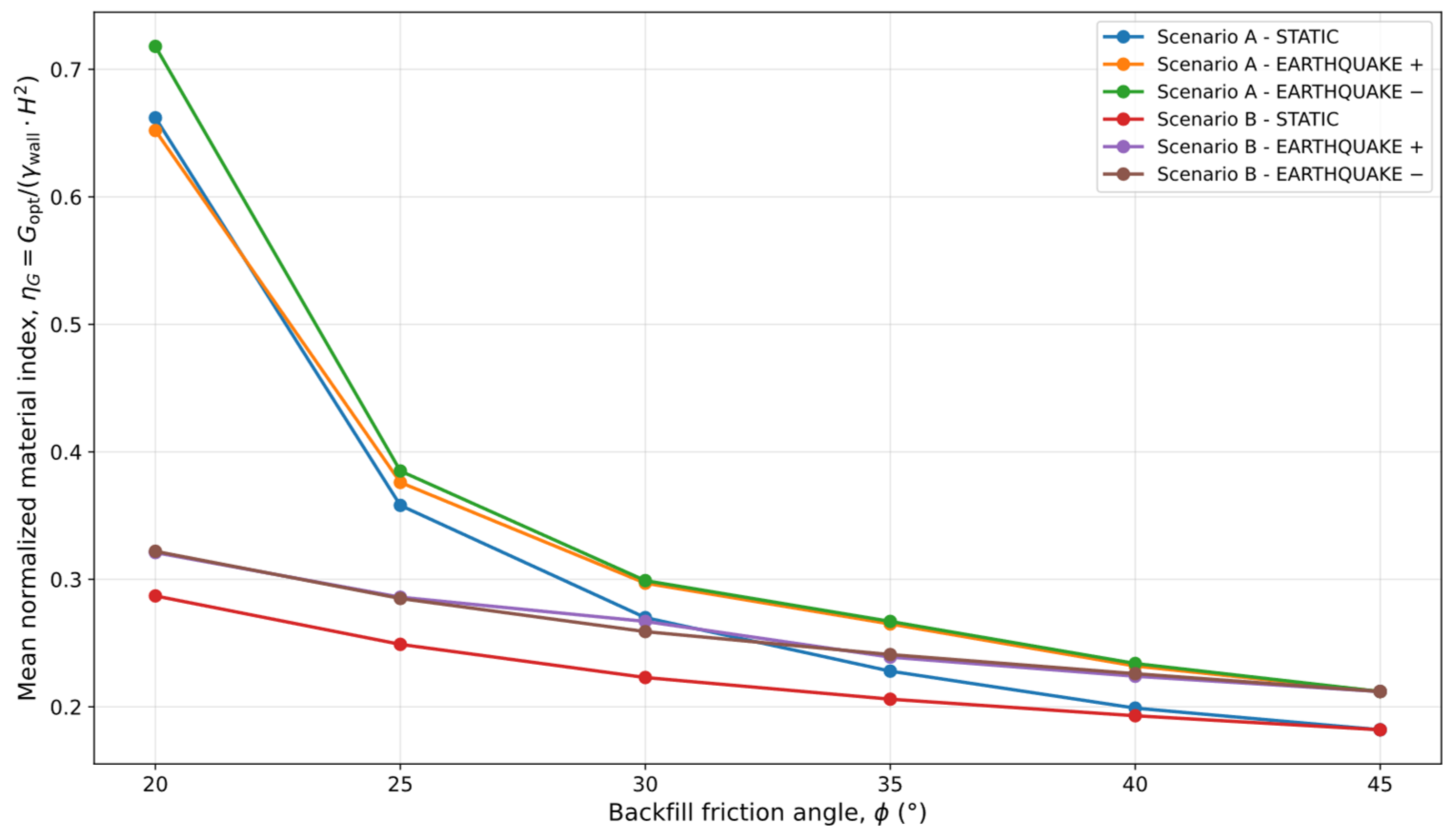
As shown in Figure 4, the normalized material demand decreases systematically with increasing backfill friction angle φ. This trend is observed for all loading conditions and in both scenarios, confirming that retained-soil strength is one of the dominant parameters controlling the optimized wall geometry.
Figure 4.
Influence of backfill friction angle on the optimized wall material.
In Scenario A, the decrease in ηG is particularly pronounced. Under STATIC loading, the mean value of ηG decreases from approximately 0.661 at φ = 20° to 0.180 at φ = 45°. Under the seismic branches, the corresponding reduction is similar, with the highest values consistently obtained for EARTHQUAKE−. In Scenario B, the overall material demand is markedly lower, and the difference between the three loading conditions becomes less pronounced at higher values of φ. For φ = 45°, both scenarios converge, since the retained and foundation soils then have identical strength properties. Thus, Figure 4 clearly demonstrates two main trends: (i) increasing the retained-soil friction angle significantly reduces the optimized material demand, and (ii) improving the foundation conditions reduces the sensitivity of the design to seismic loading. In Scenario A, φfd = φ, the observed trend therefore reflects the combined influence of backfill and foundation-soil strength; in Scenario B, φfd = 45° is fixed, allowing the backfill effect to be interpreted more independently.
4.2. Static Versus Seismic Design Conditions
The relationship between the static and seismic design branches is of particular importance, since the study distinguishes between STATIC, EARTHQUAKE+, and EARTHQUAKE− as separate loading conditions. For each parameter combination, the three loading conditions are optimized independently using the same geometrical design variables.
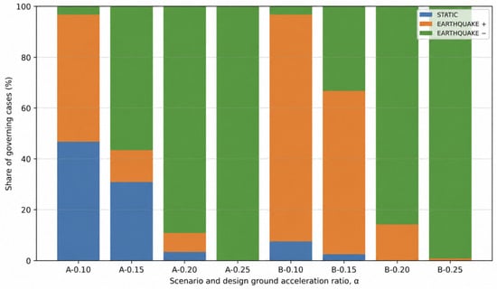
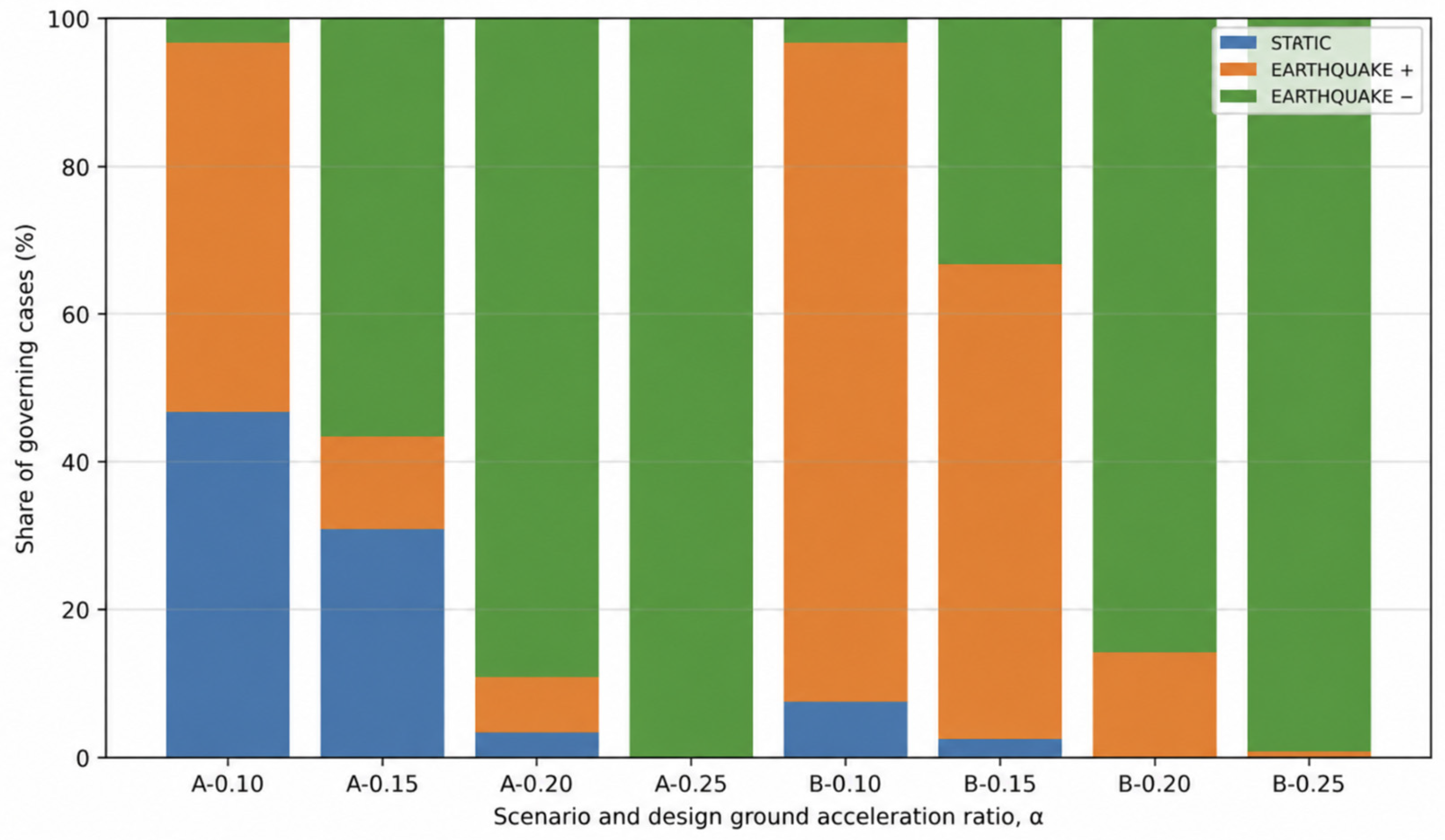
The governing branch is defined here as the loading condition requiring the largest minimum wall self-weight among the three corresponding optimal solutions. Thus, Figure 5 represents a direct comparison of the design demand associated with the independently optimized STATIC, EARTHQUAKE+, and EARTHQUAKE− cases, rather than a simultaneous optimization of the three loading conditions. At low seismic intensity, the STATIC branch may require the largest optimized wall weight because the persistent design situation is associated with higher partial safety factors than the seismic design situation. As seismic intensity increases, the additional seismic earth pressure and wall inertia progressively outweigh this difference in partial factors, and one of the seismic branches becomes governing.
Figure 5.
Loading branch requiring the largest independently optimized minimum wall weight as a function of seismic intensity.
This effect is illustrated in Figure 5, which shows the percentage of cases governed by the three loading branches for each design ground acceleration ratio α. At low seismic intensity, the governing branch is not unique. In Scenario A at α = 0.10, the optimized solution is governed by STATIC in 46.7% of cases and by EARTHQUAKE+ in 50.0% of cases, whereas EARTHQUAKE− governs only 3.3% of the cases. In Scenario B, the behavior differs: even at α = 0.10, the EARTHQUAKE+ branch already governs 89.2% of the optimized solutions. With increasing seismic intensity, the importance of the negative vertical seismic branch increases rapidly. In Scenario A, EARTHQUAKE− governs 56.7% of the cases at α = 0.15, 89.2% at α = 0.20, and 100% at α = 0.25. A similar trend is obtained in Scenario B, where EARTHQUAKE− governs 85.8% of the cases at α = 0.20 and 99.2% at α = 0.25. These results confirm that the sign of the vertical seismic coefficient cannot be neglected, since the two seismic branches do not produce equivalent design effects.
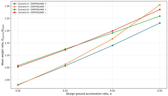
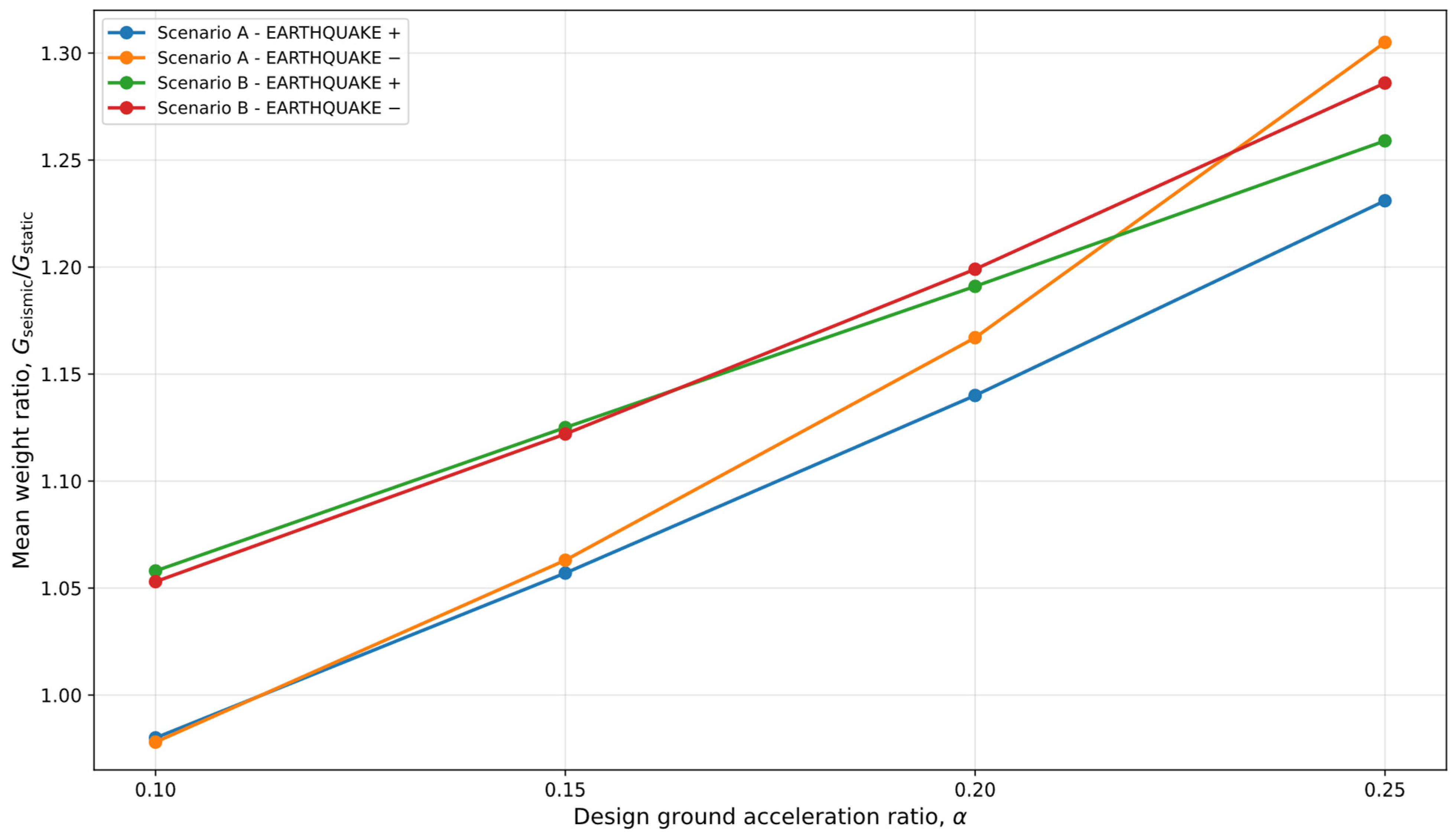
The effect of seismic intensity on the wall weight is shown more directly in Figure 6, where the mean ratios GEQ+/GSTATIC and GEQ−/GSTATIC are plotted against α. In Scenario A, the mean weight ratios remain close to unity at α = 0.10, but increase to approximately 1.23 for EARTHQUAKE+ and 1.31 for EARTHQUAKE− at α = 0.25. In Scenario B, the corresponding values reach approximately 1.26 and 1.29, respectively. Hence, seismic loading increases the required wall weight progressively, and this increase is generally larger for the EARTHQUAKE− branch.
Figure 6.
Increase in optimized wall weight under seismic loading.
The combined interpretation of Figure 5 and Figure 6 is particularly important. Figure 5 identifies which loading branch governs the design, whereas Figure 6 quantifies how much additional wall material is required relative to the static case. Together, these results show that the negative vertical seismic branch becomes increasingly critical not only because it governs more frequently, but also because it tends to require the largest wall weight.
4.3. Influence of Passive Resistance and Embedment Depth
The mobilization of passive resistance has a beneficial effect on the optimized wall weight in both scenarios. Increasing the passive-resistance mobilization factor from λp = 0 to λp = 0.3 reduces the mean optimized wall weight by approximately 8.3% in Scenario A under STATIC loading, 9.2% under EARTHQUAKE+, and 9.5% under EARTHQUAKE−. In Scenario B, the reduction is considerably larger, amounting to approximately 17.3%, 17.3%, and 17.9%, respectively.
This difference is physically consistent. In Scenario B, the competent foundation soil provides substantially larger passive resistance, so increasing λp has a more pronounced effect on the final optimum. In Scenario A, the same increase in passive resistance is less effective because the weaker foundation soil limits the mobilizable passive force.
Despite this beneficial effect, the optimizer does not systematically increase the embedment depth to exploit passive resistance. In the majority of solutions, the optimum remains at d ≈ dmin, indicating that increasing embedment is not always economical. A larger embedment depth increases the total wall height H, wall self-weight, and active earth pressure, and these adverse effects often outweigh the gain in passive resistance. Therefore, passive resistance is important, but it does not automatically imply that deeper embedment is optimal.
4.4. Governing Design Mechanisms
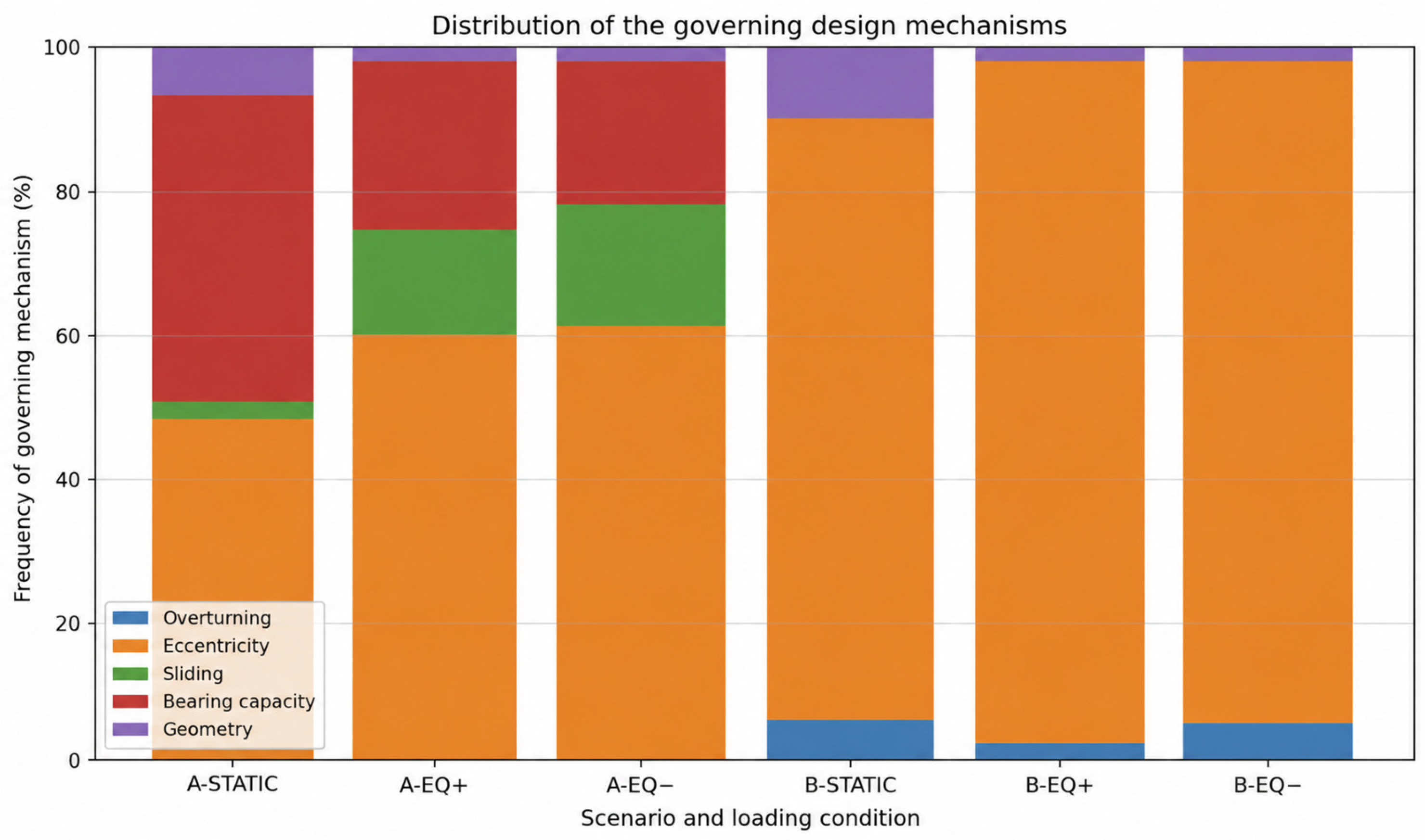
The frequency distribution of the governing design mechanisms is summarized graphically in Figure 7. The results reveal a clear contrast between the two scenarios. In Scenario A, several failure mechanisms govern the optimum depending on the loading condition. Under STATIC loading, eccentricity governs 48.3% of the cases, while bearing capacity governs 42.5% and sliding governs a small fraction. Under both seismic branches, eccentricity remains the most frequent governing mechanism, but sliding becomes significantly more important, particularly for low values of φ. Bearing capacity is still relevant, especially in the weaker-soil range, but its influence decreases as the backfill friction angle increases.
Figure 7.
Distribution of the governing design mechanisms. Frequency of overturning, eccentricity, sliding, bearing capacity, and geometry-controlled optima for both scenarios and all loading conditions.
In Scenario B, the situation is fundamentally different. The competent foundation soil almost eliminates sliding- and bearing-capacity-controlled optima. As shown in Figure 7, the optimum is governed predominantly by eccentricity, which accounts for 85.0% of the STATIC solutions, 95.6% of the EARTHQUAKE+ solutions, and 93.1% of the EARTHQUAKE− solutions. A small proportion of the solutions is governed by overturning, whereas purely geometrical limits control only a minor subset of cases.
These results show that improving foundation conditions not only reduces wall weight but also changes the governing design regime. In weaker soils, several design checks may simultaneously control the optimum across different parts of the parameter space. In competent foundation conditions, however, the design problem becomes dominated by the position of the resultant and the no-tension requirement at the wall base.
4.5. Practical Applicability of the Gravity-Wall Concept
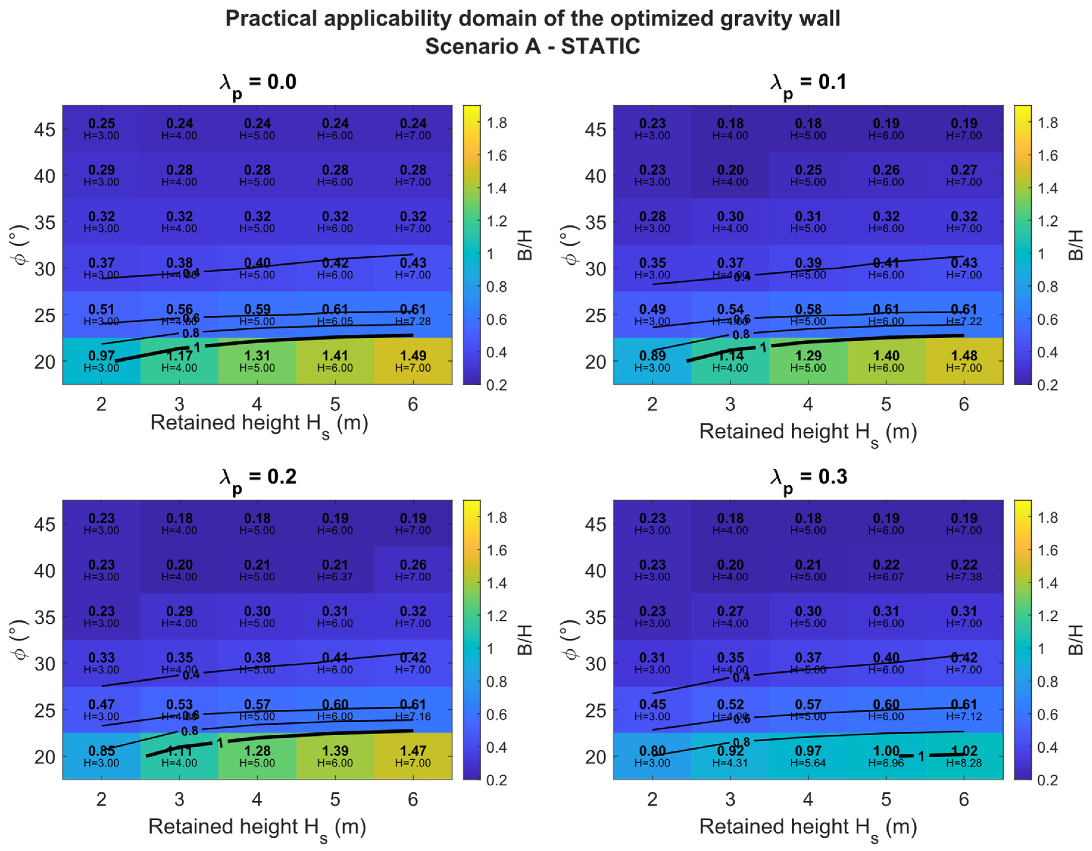
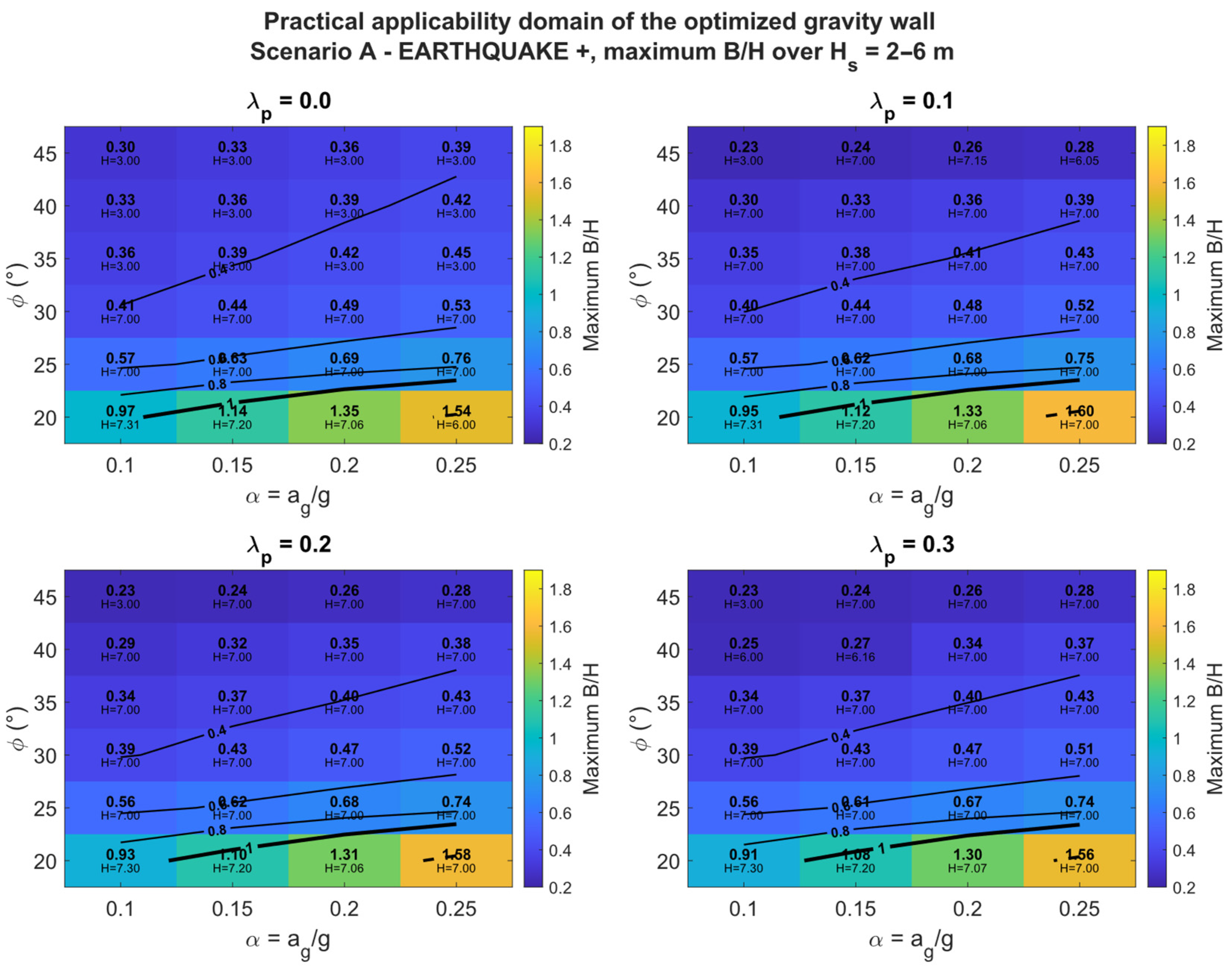
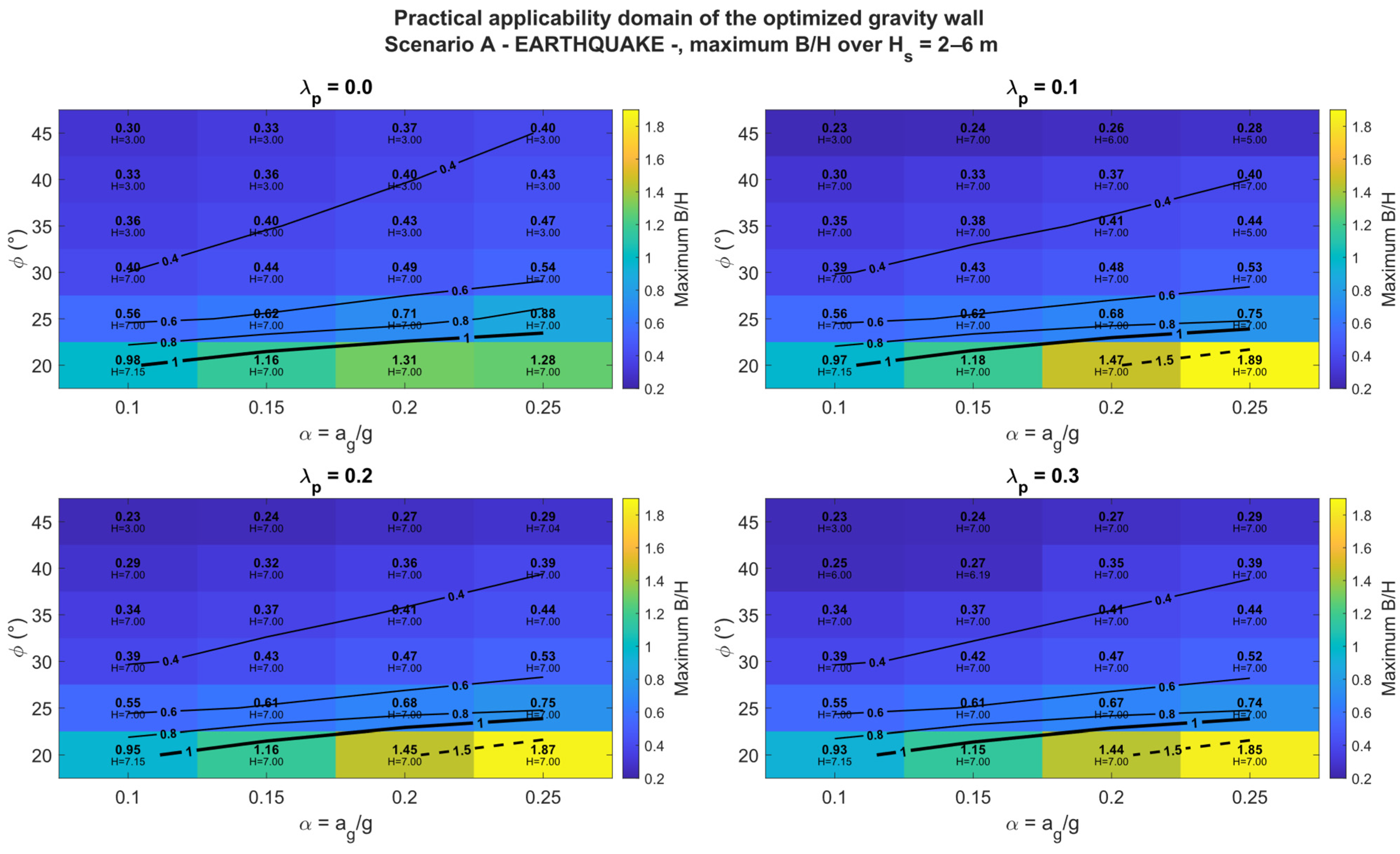
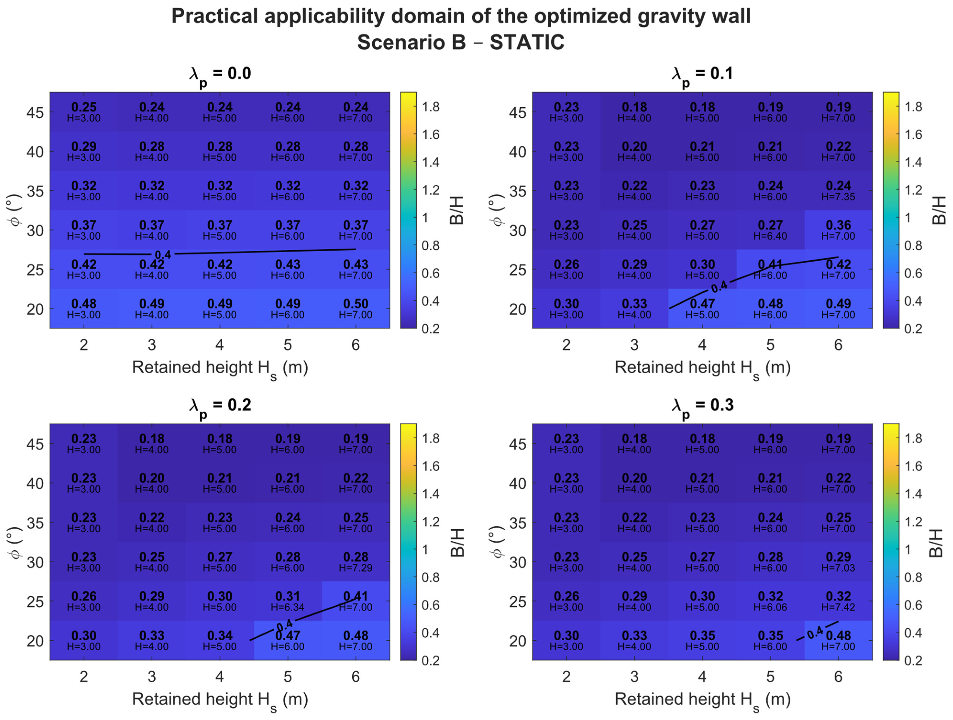
Although all optimized solutions satisfy the prescribed geotechnical and geometrical constraints, numerical feasibility does not necessarily imply that every resulting geometry represents an efficient gravity-wall solution. The optimized base-width-to-height ratio B/H was therefore examined as an additional indicator of wall massiveness and preliminary geometric efficiency. This ratio also provides a useful link with conventional preliminary proportioning rules. Published preliminary design guidance indicates base-width-to-height ratios of approximately B/H = 0.4–0.7 for masonry gravity walls [39], while values of about 0.5–0.7 are commonly used for preliminary proportioning of semi-gravity walls [40]. The B/H = 0.4, 0.6, 0.8, 1.0 and 1.5 isolines shown in Figure 8, Figure 9 and Figure 10 are therefore used primarily to visualize the progressive increase in wall massiveness and to facilitate comparison between the static and seismic solutions, rather than to define formal acceptance limits.
Figure 8.
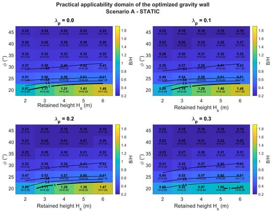
Practical applicability domain of the optimized gravity wall in Scenario A under STATIC loading. The color scale represents B/H as a function of retained height Hs, soil friction angle φ, and passive-resistance mobilization factor λp. Isolines indicate B/H = 0.4, 0.6, 0.8, 1.0 and 1.5.
Figure 9.
Practical applicability domain of the optimized gravity wall in Scenario A under EARTHQUAKE+ loading. The color scale represents the maximum B/H over Hs = 2–6 m as a function of α, φ, and λp.
Figure 10.
Practical applicability domain of the optimized gravity wall in Scenario A under EARTHQUAKE− loading. The color scale represents the maximum B/H over Hs = 2–6 m as a function of α, φ, and λp.
Under STATIC loading (Figure 8), the increase in B/H is primarily governed by the interaction between retained height and soil friction angle. The largest ratios occur for high walls founded in low-strength soil. For φ = 20°, B/H increases markedly with height and reaches values of approximately 1.4–1.5 for the highest investigated walls, considerably exceeding the proportions commonly used in preliminary gravity-wall design. In contrast, for φ ≥ 25°, the optimized ratios remain substantially lower.
The seismic analyses (Figure 9 and Figure 10) show a progressive enlargement of the high-B/H domain with increasing seismic intensity. Under EARTHQUAKE+ loading, the largest ratios remain concentrated at φ = 20° and rise to approximately 1.5–1.6 at α = 0.25. The EARTHQUAKE− branch is more demanding, producing B/H values of approximately 1.31–1.47 at α = 0.20 and up to approximately 1.85–1.89 at α = 0.25.
The comparison of Figure 8, Figure 9 and Figure 10 therefore shows a clear progression from height-controlled widening under STATIC loading, through additional seismic widening under EARTHQUAKE+, to the largest geometrical demand under EARTHQUAKE−. The fact that the largest B/H values occur only in the weakest investigated soil confirms that excessive wall massiveness results from the combined effect of low shear strength, wall height, and seismic demand. When optimized ratios become substantially larger than conventional preliminary proportions, this should be interpreted as indicating increasing wall massiveness rather than as a universal design limit. In such cases, the gravity-wall concept should be assessed against alternative retaining systems, considering construction cost, available footprint, excavation requirements, settlement, and structural integrity.
Scenario B exhibits a markedly different response (see Figure 11). Owing to the competent foundation soil, the optimized sections remain much more compact, with maximum B/H values of 0.498, 0.612, and 0.626 for STATIC, EARTHQUAKE+, and EARTHQUAKE−, respectively. These values remain close to, or below, the conventional preliminary proportioning range reported in the literature. This comparison shows that the practical efficiency of the gravity-wall concept is governed not only by wall height and seismic intensity, but, more fundamentally, by foundation soil conditions.
Figure 11.
Practical applicability domain of the optimized gravity wall in Scenario B under STATIC loading.
4.6. Influence of the Vertical-to-Horizontal Seismic Coefficient Ratio
A sensitivity analysis was performed to investigate the influence of the vertical-to-horizontal seismic coefficient ratio on the optimized wall response. All other geometric, geotechnical, and seismic input parameters were kept unchanged, and only the ratio kv/kh varied between 0.50, 0.33, and 0. The results (see Table 5) show that the magnitude of the vertical seismic component primarily controls the difference between the two seismic branches. For kv/kh = 0.50, EARTHQUAKE− generally produces the highest optimized material demand, and the difference between the two branches is largest. Reducing the ratio to 0.33 decreases this difference, whereas for kv/kh = 0 the EARTHQUAKE+ and EARTHQUAKE− solutions coincide.
Table 5.
Influence of the vertical-to-horizontal seismic coefficient ratio kv/kh on the difference between the EARTHQUAKE+ and EARTHQUAKE− optimized wall responses.
Sensitivity is substantially more pronounced in Scenario A, where the foundation soil is weaker. In Scenario B, the competent foundation soil reduces the influence of the vertical seismic component on the optimized wall weight. The coincidence of the two seismic branches for kv/kh = 0 confirms that the observed dominance of EARTHQUAKE− is directly associated with the vertical seismic action. To obtain these results, the complete seismic parametric analysis was repeated for two additional values of kv/kh. The original analysis for kv/kh = 0.50 consisted of 1920 seismic optimization runs, and the analyses for kv/kh = 0.33 and kv/kh = 0 required an additional 3840 optimization runs. Consequently, the sensitivity study comprised 5760 seismic optimization runs in total.
4.7. General Discussion and Design Implications
From an engineering point of view, the results show that the optimized geometry of a stone gravity retaining wall is controlled mainly by four interacting factors: the retained-soil friction angle, foundation-soil quality, seismic intensity, and passive-resistance mobilization.
Among these, the soil friction angle is the dominant strength parameter within the investigated parameter space, as evidenced by the pronounced downward trend in Figure 4. The foundation conditions are especially important at low values of φ, where the difference between Scenarios A and B is greatest. The seismic intensity controls both the increase in required material demand and the change in the governing load branch, as shown in Figure 5 and Figure 6. Finally, the passive-resistance mobilization factor provides a measurable but secondary benefit, which is more significant when the foundation soil is strong.
A particularly important conclusion of the study is that the two seismic branches must be treated separately. At low acceleration levels, STATIC or EARTHQUAKE+ may govern a significant part of the parameter space, but as the seismic intensity increases, the EARTHQUAKE− branch becomes dominant. This demonstrates that the sign of the vertical seismic component has a direct and practically important effect on the optimal wall design.
The B/H analysis provides an additional measure of the geometric efficiency of the optimized wall. In Scenario A, the maximum B/H increases from approximately 1.49 under STATIC loading to about 1.6 for EARTHQUAKE+ and 1.89 for EARTHQUAKE−, with the largest values occurring for φ = 20°. In contrast, Scenario B remains much more compact, with maximum B/H values of 0.498, 0.612, and 0.626 for STATIC, EARTHQUAKE+, and EARTHQUAKE−, respectively. This confirms that foundation-soil quality strongly influences not only the required wall weight but also the practical proportions of the optimized gravity wall.
4.8. Limitations and Applicability
The proposed framework is intended as a global geotechnical optimization model for the preliminary and comparative assessment of stone gravity retaining walls. The parametric results are derived for idealized homogeneous soil profiles with prescribed material properties and zero surcharge, and groundwater and pore-pressure effects are not included. The wall–soil interface is represented by a fully rough condition, and passive resistance is introduced through a prescribed mobilization factor rather than a displacement-dependent soil–structure interaction model. Accordingly, the reported trends should be interpreted within these assumptions and should not be generalized directly to layered soils, groundwater conditions, smoother interfaces, or other loading configurations without additional analysis.
The wall is treated as a gravity structure governed by global equilibrium and foundation-related limit states. Internal masonry shear failure, local stone crushing, mortar degradation, joint opening, and foundation settlement are not explicitly modeled. Consequently, satisfaction of the adopted overturning, eccentricity, sliding, and bearing-capacity constraints demonstrates feasibility within the analytical framework but does not constitute a complete structural or serviceability assessment of a constructed wall. For project-specific applications, these additional mechanisms, together with site-specific groundwater conditions, soil variability, settlements, and construction details, should be checked separately.
5. Conclusions
This study developed a multi-parametric optimization framework for trapezoidal stone gravity retaining walls subjected to static and pseudo-static seismic loading. A total of 2160 optimized designs were analyzed by varying wall height, soil friction angle, seismic acceleration and passive-resistance mobilization for two foundation-soil scenarios. The optimization simultaneously considered overturning, eccentricity, sliding, bearing capacity and geometrical constraints, enabling the governing geotechnical mechanism to be identified together with the minimum-weight geometry. The principal conclusions are:
- (1)
- The soil friction angle is the dominant strength parameter controlling material demand within the investigated parameter space. In Scenario A, the mean normalized material index under STATIC loading decreases from approximately 0.661 at φ = 20° to 0.180 at φ = 45°. This confirms the strong sensitivity of gravity-wall dimensions to soil shear strength.
- (2)
- Foundation-soil quality changes both the required wall geometry and the governing design mechanism. In Scenario A, where the retained and foundation soils have the same properties, low friction angles lead predominantly to bearing-capacity- and sliding-controlled solutions. As φ increases, eccentricity progressively becomes the governing condition. In Scenario B, the competent foundation soil largely eliminates sliding- and bearing-capacity-controlled optima, and eccentricity governs most solutions.
- (3)
- The base width B is the principal geometrical variable through which the optimized wall adapts to increasing geotechnical and seismic demand. The top width Bz remains at or close to its minimum value in most solutions, while only a small proportion of cases require embedment deeper than dmin = 1.0 m. This indicates that increasing wall width is generally more efficient than increasing top width or embedment depth within the adopted optimization framework.
- (4)
- The two seismic branches are not equivalent and must be analyzed separately. At low acceleration levels, STATIC or EARTHQUAKE+ may govern substantial portions of the parameter space. With increasing seismic intensity, however, EARTHQUAKE− becomes progressively dominant. At α = 0.25, EARTHQUAKE− governs 100% of Scenario A and 99.2% of Scenario B solutions. This demonstrates the importance of explicitly accounting for the sign of the vertical seismic component in optimized gravity-wall design. The sensitivity analysis further showed that reducing the ratio kv/kh from 0.50 to 0.33 decreases the difference between the EARTHQUAKE+ and EARTHQUAKE− branches, while for kv/kh = 0 the two branches coincide.
- (5)
- Seismic loading substantially increases material demand at higher acceleration levels. At α = 0.25, the mean optimized wall-weight ratios reach approximately GEQ+/GSTATIC = 1.23 and GEQ−/GSTATIC = 1.31 in Scenario A, and approximately 1.26 and 1.29 in Scenario B. EARTHQUAKE− therefore produces not only the most frequently governing loading condition at high seismic intensity but also, on average, the largest material demand.
- (6)
- Mobilized passive resistance improves the efficiency of the wall, but its benefit depends strongly on the foundation soil. Increasing λp from 0 to 0.3 reduces the mean optimized wall weight by approximately 8.3–9.5% in Scenario A and 17.3–17.9% in Scenario B. The larger benefit in Scenario B results from the higher passive resistance available in the competent foundation soil. Nevertheless, increasing embedment is not automatically advantageous because it simultaneously increases total wall height, self-weight and active earth pressure.
- (7)
- The B/H analysis provides a useful preliminary indicator of geometric efficiency beyond conventional limit-state verification. In Scenario A, the mean B/H increases from approximately 0.48 under STATIC loading to 0.51 for EARTHQUAKE+ and 0.53 for EARTHQUAKE−. By contrast, Scenario B remains substantially more compact, with mean B/H values of approximately 0.29, 0.36, and 0.36 for STATIC, EARTHQUAKE+, and EARTHQUAKE−, respectively. This comparison demonstrates that less favorable foundation conditions can lead to substantially more massive wall geometries even when all formal geotechnical checks are satisfied.
- (8)
- The optimization reveals transitions between distinct geotechnical design regimes. Weak soils are governed mainly by bearing capacity and sliding, whereas stronger foundation conditions shift the optimum toward eccentricity and the no-tension requirement. The optimization framework therefore provides more than a minimum-weight solution: it identifies the loading condition, failure mechanism and parameter region governing the optimum design.
From a practical design perspective, the results show that a gravity-wall solution should not be evaluated solely on the basis of satisfying individual stability checks. The combined consideration of optimized weight, governing mechanism and B/H provides a more informative assessment of whether the resulting section remains mechanically and geometrically efficient. Particularly in weak soils subjected to strong seismic loading, the rapid increase in B/H indicates that alternative retaining systems should be considered rather than relying exclusively on further enlargement of the gravity-wall section.
The conclusions are valid within the adopted analytical framework, which employs Coulomb-type static earth pressure, Mononobe–Okabe pseudo-static seismic pressure, prescribed passive-resistance mobilization and idealized homogeneous soil profiles. The analyses also assume a fully rough wall–soil interface. Therefore, the reported trends are most directly applicable to strongly rough stone–soil contacts, while smoother or more regular interfaces may exhibit lower interface friction and consequently different optimized wall geometries. Internal masonry shear failure, local stone crushing, mortar degradation, and joint opening were outside the scope of the present global geotechnical optimization. Future research should therefore address nonlinear soil–structure interaction, displacement-dependent passive resistance, groundwater and pore-pressure effects, layered and spatially variable soils, and dynamic time-history analyses. Extending the present minimum-weight formulation toward multi-objective cost–CO2–material optimization and direct comparison with alternative retaining systems would also provide a useful basis for defining the practical transition from massive gravity walls to more efficient structural solutions.
Funding
This research was funded by the Slovenian Research Agency (grant number P2-0268).
Institutional Review Board Statement
Not applicable.
Informed Consent Statement
Not applicable.
Data Availability Statement
The data presented in this study are available within the article.
Conflicts of Interest
The author declares no conflicts of interest.
References
- Fernandes, M.M. Analysis and Design of Geotechnical Structures, 1st ed.; CRC Press: Boca Raton, FL, USA, 2020. [Google Scholar]
- Voit, K.; Hron, J.; Frei, G.; Adamcova, R.; Zeman, O. Mechanism and Internal Stability of Supportive Stone Constructions. Materials 2022, 15, 3175. [Google Scholar] [CrossRef] [Scilit] [PubMed]
- EN 1997-1:2004+A1:2013; Eurocode 7: Geotechnical Design—Part 1: General Rules. European Committee for Standardization: Brussels, Belgium, 2004.
- EN 1998-5:2004; Eurocode 8: Design of Structures for Earthquake Resistance—Part 5: Foundations, Retaining Structures and Geotechnical Aspects. European Committee for Standardization: Brussels, Belgium, 2004.
- Richards, R.; Elms, D.G. Seismic Behavior of Gravity Retaining Walls. J. Geotech. Eng. Div. 1979, 105, 449–464. [Google Scholar] [CrossRef] [Scilit]
- Khan, S.A.; Karray, M.; Paultre, P. Seismic Behavior of Retaining Walls: A Critical Review of Experimental and Numerical Findings. Geotechnics 2025, 5, 25. [Google Scholar] [CrossRef] [Scilit]
- Sun, Z.; Wang, W. Seismic Non-Limited Active Earth Pressure Analysis of Retaining Walls Under Rotation-About-the-Base Mode. Appl. Sci. 2025, 15, 4202. [Google Scholar] [CrossRef] [Scilit]
- Al-Taie, A.J.; Ahmed, M.D. Seismic Performance of Earth Retaining Structures under Case Histories Earthquakes. J. Kejuruter. 2026, 38, 1343–1360. [Google Scholar] [CrossRef] [Scilit] [PubMed]
- Wang, X.; Dang, F.; Cao, X.; Zhang, L.; Gao, J.; Xue, H. Solution for Active and Passive Earth Pressure on Rigid Retaining Walls with Narrow Backfill. Appl. Sci. 2025, 15, 1750. [Google Scholar] [CrossRef] [Scilit]
- Lin, Y.; Yang, C.; Xu, A.; Ma, H.; Li, Y.; Wang, C. Parameter Optimization Analysis of Buttressed Pile Foundation Beam Retaining Wall Under Seismic Action. Buildings 2025, 15, 1748. [Google Scholar] [CrossRef] [Scilit]
- Mylonakis, G.; Kloukinas, P.; Papantonopoulos, C. An Alternative to the Mononobe–Okabe Equations for Seismic Earth Pressures. Soil Dyn. Earthq. Eng. 2007, 27, 957–969. [Google Scholar] [CrossRef] [Scilit]
- Conti, R.; Viggiani, G.M.B.; Cavallo, S. A Two-Rigid Block Model for Sliding Gravity Retaining Walls. Soil Dyn. Earthq. Eng. 2013, 55, 33–43. [Google Scholar] [CrossRef] [Scilit][Green Version]
- Kloukinas, P.; Scotto di Santolo, A.; Penna, A.; Dietz, M.; Evangelista, A.; Simonelli, A.L.; Taylor, C.; Mylonakis, G. Investigation of Seismic Response of Cantilever Retaining Walls: Limit Analysis vs Shaking Table Testing. Soil Dyn. Earthq. Eng. 2015, 77, 432–445. [Google Scholar] [CrossRef] [Scilit]
- Deyanova, M.; Lai, C.G.; Martinelli, M. Displacement—Based Parametric Study on the Seismic Response of Gravity Earth-Retaining Walls. Soil Dyn. Earthq. Eng. 2016, 80, 210–224. [Google Scholar] [CrossRef] [Scilit]
- Conti, R.; Viggiani, G.M.B. On the Performance-Based Seismic Design of Yielding Retaining Structures. Soil Dyn. Earthq. Eng. 2023, 174, 108172. [Google Scholar] [CrossRef] [Scilit]
- Tsantilas, L.; Garini, E.; Gazetas, G. Insight into the Seismic Response of Gravity Retaining Walls. Géotechnique 2025, 75, 1141–1167. [Google Scholar] [CrossRef] [Scilit]
- Talatahari, S.; Sheikholeslami, R.; Shadfaran, M.; Pourbaba, M. Optimum Design of Gravity Retaining Walls Using Charged System Search Algorithm. Math. Probl. Eng. 2012, 2012, 301628. [Google Scholar] [CrossRef] [Scilit]
- Talatahari, S.; Sheikholeslami, R. Optimum Design of Gravity and Reinforced Retaining Walls Using Enhanced Charged System Search Algorithm. KSCE J. Civ. Eng. 2014, 18, 1464–1469. [Google Scholar] [CrossRef] [Scilit]
- Konstandakopoulou, F.; Tsimirika, M.; Pnevmatikos, N.; Hatzigeorgiou, G.D. Optimization of Reinforced Concrete Retaining Walls Designed According to European Provisions. Infrastructures 2020, 5, 46. [Google Scholar] [CrossRef] [Scilit]
- Gao, G.-H.; Li, D.-Q.; Cao, Z.-J.; Wang, Y.; Zhang, L. Full Probabilistic Design of Earth Retaining Structures Using Generalized Subset Simulation. Comput. Geotech. 2019, 112, 159–172. [Google Scholar] [CrossRef] [Scilit]
- Santos, M.G.C.; Silva, J.L.; Beck, A.T. Reliability-Based Design Optimization of Geosynthetic-Reinforced Soil Walls. Geosynth. Int. 2018, 25, 442–455. [Google Scholar] [CrossRef] [Scilit]
- Xu, C.; Gordan, B.; Koopialipoor, M.; Armaghani, D.J.; Tahir, M.M.; Zhang, X. Improving Performance of Retaining Walls Under Dynamic Conditions Developing an Optimized ANN Based on Ant Colony Optimization Technique. IEEE Access 2019, 7, 94692–94700. [Google Scholar] [CrossRef] [Scilit]
- Pham, Q.H.; Do, Q.T. On Optimization of Gravity Retaining Wall Considering the Dimension of the Stone Base. In Lecture Notes in Civil Engineering; Springer: Berlin/Heidelberg, Germany, 2025; Volume 590, pp. 431–437. [Google Scholar]
- Varga, R.; Žlender, B.; Jelušič, P. Multiparametric Analysis of a Gravity Retaining Wall. Appl. Sci. 2021, 11, 6233. [Google Scholar] [CrossRef] [Scilit]
- Varga, R.; Jelušič, P. Failure Probability of an Optimally Designed Gravity Retaining Wall. ASCE-ASME J. Risk Uncertain. Eng. Syst. A Civ. Eng. 2022, 8, 04022007. [Google Scholar] [CrossRef] [Scilit]
- Powrie, W.; Harkness, R.M.; Zhang, X.; Bush, D.I. Deformation and Failure Modes of Drystone Retaining Walls. Géotechnique 2002, 52, 435–446. [Google Scholar] [CrossRef]
- Villemus, B.; Morel, J.C.; Boutin, C. Experimental Assessment of Dry Stone Retaining Wall Stability on a Rigid Foundation. Eng. Struct. 2007, 29, 2124–2132. [Google Scholar] [CrossRef] [Scilit]
- Mundell, C.; McCombie, P.; Heath, A.; Harkness, J.; Walker, P. Behaviour of Drystone Retaining Structures. Proc. Inst. Civ. Eng.-Struct. Build. 2010, 163, 3–12. [Google Scholar] [CrossRef] [Scilit]
- Colas, A.-S.; Morel, J.-C.; Garnier, D. Assessing the Two-Dimensional Behaviour of Drystone Retaining Walls by Full-Scale Experiments and Yield Design Simulation. Géotechnique 2013, 63, 107–117. [Google Scholar] [CrossRef] [Scilit]
- Alejano, L.R.; Pérez-Rey, I.; Muñiz-Menéndez, M.; Ding, B. Dry Masonry Retaining Walls: Physical Models and Comparison with Analytical and Numerical Approaches. Rock Mech. Rock Eng. 2025. [Google Scholar] [CrossRef] [Scilit]
- Alejano, L.R.; Veiga, M.; Gómez-Márquez, I.; Taboada, J. Stability of Granite Drystone Masonry Retaining Walls: II. Relevant Parameters and Analytical and Numerical Studies of Real Walls. Géotechnique 2012, 62, 1027–1040. [Google Scholar] [CrossRef] [Scilit]
- Savalle, N.; Monchal, C.; Vincens, E.; Forcioli, S.; Lourenço, P.B. Static and Seismic Design of Dry Stone Retaining Walls (DSRWs) Following Eurocode Standards. Eng. Struct. 2023, 274, 114847. [Google Scholar] [CrossRef] [Scilit]
- Ding, B.; Pérez-Rey, I.; González-Fernández, M.A.; Yuan, S.; Tang, H.; Alejano, L.R. Optimizing Shape Design in Drystone Retaining Walls: A Multi-Scope Approach Focusing on Failure Mechanisms. Constr. Build. Mater. 2025, 489, 142116. [Google Scholar] [CrossRef] [Scilit]
- Singh, P.; Chakraborty, T.; Mahajan, P. Discrete Element Study of Stresses and Deformation on Gravity Retaining Wall under Static Loading. Granul. Matter 2024, 26, 48. [Google Scholar] [CrossRef] [Scilit]
- Perozzi, D.; Puzrin, A.M. Experimental Study of the Earth Pressure Evolution on a Model Wall Rotating about Its Base. J. Geotech. Geoenviron. Eng. 2024, 150, 04024048. [Google Scholar] [CrossRef] [Scilit]
- Lancellotta, R. Lower-Bound Approach for Seismic Passive Earth Resistance. Géotechnique 2007, 57, 319–321. [Google Scholar] [CrossRef] [Scilit]
- Fan, X.; Xu, C.; Liang, L.; Chen, Q.; Deng, J. Analytical Solution for Displacement-Dependent Passive Earth Pressure on Rigid Walls with Various Wall Movements in Cohesionless Soil. Comput. Geotech. 2021, 140, 104470. [Google Scholar] [CrossRef] [Scilit]
- Potyondy, J.G. Skin Friction between Various Soils and Construction Materials. Géotechnique 1961, 11, 339–353. [Google Scholar] [CrossRef] [Scilit]
- Look, B.G. Handbook of Geotechnical Investigation and Design Tables; CRC Press: London, UK, 2017. [Google Scholar]
- Clayton, C.R.I.; Woods, R.I.; Bond, A.J.; Milititsky, J. Earth Pressure and Earth-Retaining Structures; CRC Press: Boca Raton, FL, USA, 2014. [Google Scholar]

Disclaimer/Publisher’s Note: The statements, opinions and data contained in all publications are solely those of the individual author(s) and contributor(s) and not of MDPI and/or the editor(s). MDPI and/or the editor(s) disclaim responsibility for any injury to people or property resulting from any ideas, methods, instructions or products referred to in the content. |
© 2026 by the author. Licensee MDPI, Basel, Switzerland. This article is an open access article distributed under the terms and conditions of the Creative Commons Attribution (CC BY) license.