


Abstract
Unitised structural sealant-glazed (SSG) façades with glass bonded directly to timber frames offer enhanced sustainability and superior thermal performance compared with conventional aluminium-framed systems. Becaxuse bonded joints must provide continuous structural support to the glass throughout the façade’s service life, long-term durability is the key requirement. Standardised testing protocols are designed for glass and metal substrates, making some of them incompatible with timber substrates. To verify the mechanical suitability of the concept of direct bonding to timber, an experimental holistic artificial ageing (HAA) method suitable for the timber substrate was developed to complement standardised testing protocols. The core objective of the designed approach is to simulate realistic conditions under which façades are subjected to synergistic combinations of environmental and mechanical loads. These combined actions are integrated into a synchronous timeframe, with a 6 h ageing cycle representing each year of the façade’s 50-year service life. The HAA was conducted on specimens of the genera larch, cedar, and oak, as well as on aluminium for comparison. The impact of the ageing on the strength and stiffness of the silicone joint was assessed by uniaxial tensile tests that were conducted on both non-aged and aged specimens. Despite a slight decrease in the mechanical properties of aged specimens (3.4% in strength and 24.9% in stiffness), they remained functional and compliant with legislative requirements. The results demonstrate the suitability of this HAA method for practical use, as the testing duration (approximately 7–8 months after the start of the project) and required effort (roughly 0.4–0.5% of a medium-large project budget) can be accommodated within a project timeline. Experimental results also demonstrate that joints composed of materials used in the test may be used in practice.
1. Introduction
Unitised curtain wall façades are widely used in building construction. The panels consist of a supporting frame, usually made of extruded aluminium profiles (rarely, stainless steel, bronze, pultrusion, or timber), and an infill, which may be transparent or opaque. The panels are manufactured at a production facility and, once finished, they are transported to the construction site and installed on the building’s main structure (Figure 1). Fast assembly, lower installation costs, and improved quality control are advantages that make these curtain wall systems particularly suitable for high-rise building applications. Maximising repetitive detailing and minimising the number of unit types have the greatest effect on how fully these benefits are realised.
Figure 1.
Installation of a curtain wall unit.
Extruded aluminium remains the dominant material for frames of most curtain walls, with a proven record of successful application [1]. However, as climate responsiveness, energy use, and thoughtful utilisation of resources have become increasingly important over the past two decades, the entire engineering framework is also adjusting to the sustainability imperative in accordance with legislative strategy [2].
It is therefore not surprising that scientific and technological research is also shifting its focus towards solutions that reduce or even eliminate aluminium from the frame, with timber as a possible alternative [3,4,5,6,7,8,9,10,11,12,13,14,15]. Timber is well known as a renewable, low-carbon material, capable of storing CO2 (by capturing it from the atmosphere and releasing oxygen), thereby reducing the embedded carbon footprint of the entire façade. In comparison with aluminium curtain wall frames, the environmental impact of timber frames is significantly lower [3,4], and the thermal properties of timber curtain walls are even better [6,7,8], due to the low thermal conductivity of timber.
A life-cycle assessment (LCA) study indicated that, compared with conventional aluminium façades, timber-glass façades generate significantly fewer CO2 emissions while exhibiting greater energy efficiency [14]. More recent studies’ life-cycle assessments (LCAs) of unitised curtain wall (UCW) and unitised timber envelope (UTE) evaluate global warming potential (GWP) across key stages, including material extraction, transportation, construction, replacement, end-of-life scenarios, and net benefits and loads. However, in these studies, the analysis of UCWs covers only those with aluminium frames, as there are none with timber frames yet on the market [4,5]. Both these recent studies are a continuation of the research in which a unitised wall envelope (mega-panels) with cross-laminated timber (CLT) framing and various cladding options (including glazing), intended for use in mid-rise to tall buildings and with the potential for full prefabrication, is presented [10]. The in-plane load capacity of glass diapraghms in timber frames has been successfully investigated [11]. Experimental research on the development of the hybrid (plywood-aluminium) curtain wall façade is reported in Ref. [12]. Ref. [13] presents the concept of a unitised curtain wall with a timber-only frame (made of accoya and spruce glulam), supported by experimental tests and simulations that assess the impact of challenges such as moisture control and fire. A comprehensive overview of the state of the art in timber–glass composites is presented in Ref. [15], and the systematised knowledge provides a deeper understanding of their structural particularities and their thermal and ecological advantages and disadvantages (compared to existing systems with aluminium-timber frames). In the aforementioned research, general guidelines for the design and development of unitised timber curtain walls bonded with structural silicone were also proposed, and potential environmental, thermal, and structural advantages over conventional timber–aluminium systems were assessed in a case study.
Recently, unitised curtain wall façades have emerged that partially use timber instead of aluminium for the bulk of the frame, while retaining a small aluminium profile for the bonding area. Due to its dimensional and mechanical stability, glued laminated timber (glulam) is the preferred material for the frame. The metal is retained for the bonding area, as this allows the use of structural sealant glazing (SSG) expertise accumulated over more than 50 years [16].
1.1. Innovative TimberCW Concept
1.1.1. General
To completely exclude aluminium from the composition of the façade panels and thereby minimise the carbon footprint of the façade, as well as to address other issues, including the loosening of connecting bolts caused by differential movements between the aluminium and wooden parts of the frame, the innovative TimberCW concept (Figure 2) has been developed. In this concept, the infill glass is bonded directly to the wooden frame using structural sealant glazing (SSG) with bonding silicone. This research on the durability of the bonded glass-to-timber joint is a progression of the development of TimberCW.
Figure 2.
TimberCW: (a) façade panel; (b) cross-section through the frame: 1—structural silicone, 2—timber frame, 3—insulating glass, 4—gasket.
The concept and properties of the TimberCW façade [7,8,17] have been presented at several previous conferences. Laboratory tests performed on the TimberCW concept have demonstrated important properties of the façade, including the following:
- Mullion bending test;
- Transfer of horizontal load through the stack joint;
- Mechanical testing of the glass-to-wood SSG joint;
- Comprehensive testing of the façade performance mock-up (PMU) consisting of six panels at full scale (1500 × 3750 mm) [18]. Tests have included the following:
- ○
- resistance to wind load;
- ○
- serviceability;
- ○
- accommodation of main structural frame movements;
- ○
- air permeability;
- ○
- watertightness;
- ○
- resistance to thermal cycles;
- ○
- impact resistance;
- ○
- resistance to wind load—safety;
- ○
- testing of the façade unit after natural ageing;
- ○
- testing of the seismic resistance [19,20].
1.1.2. Natural Ageing
TimberCW units used in the full-scale PMU testing in 2013 were removed from the test rig after testing and stored outdoors in a horizontal position under a PVC cover. During this storage period, the units were exposed to natural temperature variations and humidity. In 2022, one of these units was installed in front of the pressure chamber to test its ultimate resistance to internal overpressure after nearly ten years of natural ageing (Figure 3a). The units were originally designed for a design wind load of 2 kPa. The test pressure at which the unit failed during the ultimate test was 9.5 kPa, much higher than the design wind load. The silicone joint did not fail; the breakage resulted from splitting of the glulam mullion at the corner connection to the lower transom (Figure 3b). The uniform tensile stress in the silicone at the time of breakage was 285 kPa.
Figure 3.
Ultimate test on a TimberCW unit: (a) unit in front of the pressure chamber; (b) splitting of the glulam mullion.
1.2. Problem Definition and Motivation for the Research
When developing a new product concept for practical application, devising a verification method to demonstrate its validity, particularly its durability, is a challenge. Often, such testing procedures exist for similar products but are not directly applicable to the concept being investigated. The principle of structural sealant glazing (SSG), which bonds glass units to the frame of unitised curtain wall façades, is no exception.
Current standardised testing methods for SSG joints assume that only three materials are used as adherends for SSG bonding: glass, aluminium (painted or anodised), or stainless steel. These procedures expose specimens to more severe conditions than they might experience during the building’s service life. Still, since they do not affect these three basic materials, they are deemed adequate and are widely used in practice. However, despite their proven effectiveness, common artificial ageing procedures for SSG cannot be applied to wooden substrates, as they damage the wood, given its well-known physical and mechanical properties (anisotropy, hygroscopy, rheological behaviour, and tendency to brittle failure and dimensional instability). Further, existing durability tests for SSG are based on individual actions, with single specimens exposed to a single action at a time, and they do not account for the interaction effects of multiple simultaneous actions.
1.3. Research Background
1.3.1. Silicone Bonding—Applications and Mechanical Performance
Bonding silicone is an adhesive with high resistance to atmospheric conditions and to the temperature range expected during its service life. It has low sensitivity to ultraviolet radiation and has mechanical properties suitable for both static and dynamic actions on façades. Improvements to its already low thermal conductivity are being investigated [21]. A key property of bonding silicone, which makes it particularly suitable for façade use, is that its adhesion to the substrate (glass and frame) is stronger than its internal cohesion. Therefore, in a properly designed and executed SSG joint detail, failure of the silicone bond occurs by internal fracture within the body of the silicone, rather than by detachment from the surface of the adherents. Thus, the calculation of silicone joints focuses on the mechanical properties of the silicone itself, not on its adhesion to the substrate. Silicone is a hyperelastic material, and its mechanical properties depend on its shape, as investigated in Ref. [22], and on the duration of the load [23].
Bonding glass to wood (Figure 4) with structural silicone has been the subject of numerous studies. Between 2000 and 2002, TU Munich and IFT Rosenheim conducted systematic research and extensive laboratory tests, confirming that a high-quality, uniform structural bond between silicone and wood is achievable [24]. A foundational study on combining timber and glass with structural adhesives showed that silicone, due to its low stiffness, has a high deformation capacity, enabling it to deform alongside the wood [25]. Considering the effects of moisture-induced timber deformations on the adhesive interface, this is an important feature and an advantage over other adhesives (acrylate and polyurethane) investigated in this study. Further research on three wood species (meranti, white oak, and pine) has shown that the quality of the bonded joint (tensile adhesion strength) depends on the type of wood substrate used and that priming the adhesion surface has a beneficial effect, as this treatment decreases performance variations among different species and improves overall adhesion performance [26].
Figure 4.
Bonding silicone to a wooden substrate.
The possibility of constructing stick façades with a secondary wooden frame to which glass is glued has been investigated and demonstrated, including the potential for using a silicone bond in timber-glass composites (TGC) [9]. Residential windows with glass bonded to the frame using silicone are in operation in Switzerland [27]. A significant study on the resistance of silicone bonding to wood was conducted using seven wood species, three pretreatment types for moisture exposure (including water immersion), and three wood surface treatments. The results showed the concept’s viability but also highlighted the strong influence of wood species, moisture content, and surface preparation on silicone contact, with some combinations failing due to loss of adhesion [28]. In a previous study, eleven commercially available adhesives were grouped into three categories based on stiffness (low, medium, and high) and tested across various temperatures (−20 °C to +80 °C) and load rates (1, 5, and 50 mm/min). The findings revealed a clear dependency: higher load rates and lower temperatures enhance both strength and stiffness. Furthermore, failure modes were categorised by adhesive type. Silicones (soft adhesives) showed an approximately linear stress–strain relationship, whereas stiff adhesives (epoxies) demonstrated ductile behaviour after reaching a maximum load [29]. The different impacts on the stiffness and ductility of in-plane-loaded glass-timber diaphragms have been investigated between stiff (two-part epoxy) and deformable adhesives (polyurethane and silicone) [30].
Another study of glass–silicone–timber structures [31] was reported, which involved conditioning of specimens in various ways, including immersion in water for 7 days, exposure to a xenon-arc lamp, subjecting up to 20,000 cycles of the 30% shear deformation, and exposing a full-scale SSG unit to 2.2 million cycles of the tensile load generating 31 kPa of stress. The silicone used was Sealant-FC-295SG by Shin-Etsu Chemical Co. A high rate of adhesive failure was observed after immersion in water, consistent with other research. The tensile test after the cyclic shear loading showed a 10% decrease in strength and lower stiffness. The tensile test after tensile cycling showed a 22% decrease in strength. It may be discussed whether such a high number of cycles is justified. Peeling of wood along the grain direction was also observed, as reported by other researchers [22,26].
Other researchers have compared the adhesive strength of silicone bonds with other adhesives, such as acrylates and polyurethanes, and tested specimens with regard to shear and tension [32,33,34]. Although these adhesives achieve significantly higher adhesive and cohesive strengths, they do not offer the same resistance to atmospheric influences, primarily water and ultraviolet radiation, as silicone does [35], which poses a challenge for their use in façade construction. Furthermore, silicone offers high deformability and can be installed in significant thicknesses (6–30 mm), making it suitable for façade applications because it can easily accommodate differential movement between the glass and the frame. Some specific shear tests on silicone timber-glass bonding assess the strength and ductility of these joints in curtain wall systems and other applications (e.g., window frames) [36].
Silicone joints also provide high seismic resistance, which benefits the façade. Silicone thickness in the joint is at least 6 mm, providing additional ductility by allowing the frame to deform in-plane rather than being constrained by the stiff glass pane, thereby dissipating seismic energy. This has been investigated in Refs. [19,20,37].
1.3.2. Durability Issues—State of the Art and Gaps in the Normative Framework
However, although various investigations into the mechanical properties of SSG joints to wood have shown satisfactory results, data on their durability remain insufficient. In an extensive study of the use of different adhesives (silicone, polyurethane, epoxy silane, acrylate, epoxy) for bonding glass (float and tempered) to timber (birch, pine), various approaches were used to test the bonds in shear. The temperature and timber moisture contents varied. The timber-glass specimens were artificially aged by exposure to UV light, a detergent solution, and a sulfur dioxide (SO2)-containing atmosphere [38]. An accelerated ageing test was conducted based on the four scenarios defined in the IFT guideline VE-08/2, comprising UV exposure, immersion in cleaning solution, changes in moisture content (wetting/drying), and exposure to a SO2 atmosphere. It was demonstrated that silicone, characterised by its low stiffness and high weathering resistance, exhibited excellent stability under those conditions. Reference was made to practical design examples, including the timber–glass composite façade system developed by UNIGLAS [39]. In another study, shear and tension tests were conducted on small timber-glass specimens bonded with a two-component silicone adhesive. The specimens were subjected to wetting–drying, freezing–thawing, UV exposure, acid treatment, and high-temperature exposure before testing. Hydrochloric acid and freezing–thawing were identified as the most significant ageing factors, strongly influencing the adhesive’s properties under shear forces [40].
The quality of SSG joints to glass, aluminium, and stainless steel substrates is tested according to the provisions of the European Assessment Document EAD 090010-00-0404 (formerly ETAG002) [41], and to a lesser extent, EN 13022-2 [42], or according to ASTM C1401-23 in the USA [43], but wood is not covered as a substrate. The durability tests in these documents expose specimens of the listed substrates to separate ageing processes and single actions, without considering the effects of combined actions on individual specimens. To compensate for this uncertainty, a relatively high threshold for retained properties is required compared to unaged silicones. The test procedures used in the above-referenced documents are also not fully representative of real conditions in a façade; for example, the permanent water-immersion test was specifically designed to confirm the quality of the bonding silicone. This test could be implemented because it did not affect the metallic and glazed substrates, but it was critical for silicone. Transposing this test to other substrates is therefore neither representative nor appropriate. The ageing methods used by EAD 090010-00-0404, while suitable for glass and metal, damage the wooden substrate and do not reflect the actual conditions the wood will face during its service life. No standardised durability test procedure allows artificial ageing of a specimen in the laboratory under the combined atmospheric and mechanical influences experienced by the SSG joint in service.
Several studies have examined the durability of silicone adhesive bonds to metal substrates. Theoretically, durability was investigated using a probabilistic methodology to establish a calculation method in accordance with Eurocode 0 [23]. Various studies have focused on cyclic fatigue testing of silicone, recognising it as the primary cause of the decrease in the mechanical properties of aged silicone.
The influence of cyclic loading was examined [44] by applying the tensile load-cycling procedure from EAD [41] to silicone Dowsil 983 with aspect ratios (bite to thickness) of AR = 1, 2, 3, and 4. The cycling procedure was performed using three different peak loads: 140 kPa, 240 kPa, and 500 kPa. The tensile breaking strength generally did not decrease after cycling, but the stiffness, expressed as the stress at 12.5% strain, decreased after cycling, although this was not observed in all specimens.
Another study used laboratory durability testing of glass-to-metal bonds [45]. Several sealants were investigated: a stiff epoxy, 3M™ Scotch-Weld™ 9323 B/A; a flexible MS-polymer, Soudaseal 270 HS; and a structural silicone, Sikasil® SG-500. It was found that exposure to UV radiation did not affect the silicone; the performance of the silicone after exposure to moisture was outstanding, and thermal cycling did not significantly affect the silicone.
1.3.3. Holistic Artificial Ageing
Holistic durability testing, aimed at mimicking real façade conditions under the combined effects of various actions, was conducted at BAM [46,47,48,49,50,51,52]. In that research, the aluminium specimens were subjected to combined atmospheric and mechanical influences for 50 days, with each 24 h representing one year of service life.
In other research [53], the influence of single actions and their cumulative effect on sealant performance was investigated. Various combinations of temperature, UV irradiation, water, and load were sequentially applied to specimens. A tool for prediction of the ageing effects was proposed. UV irradiation showed the strongest synergistic effect when combined with other actions, and temperature had the greatest single impact on the sealant’s mechanical properties. However, the sealants used were not silicone, since the silicon–oxygen backbone was replaced with the more economical calcium carbonate (CaCO3). Calcium carbonate, in addition to causing surface chalking and making the sealant stiffer, may dissolve in water under UV irradiation and temperature, leaving gaps and crystallising in the sealant body, which may damage the sealant structure and reduce its mechanical properties. Hence, the results of that research may not be compared to the results obtained in this research.
1.3.4. Natural Ageing
Several reports document the effects of natural ageing on samples collected from buildings with varying years in service.
In 1985, a structurally glazed and toggle-secured glass-aluminium façade was built at IFT Rosenheim, Germany. The outer glass was supported only by structural silicone and was exposed to wind, meteorological actions, climatic load, and the dead load of the glass pane. In 2012, it was dismantled and, after 2 years in storage, samples were taken and tested. It was found that the residual tensile breaking strength was at 79% of the strength measured at the time the façade was built, and the residual shear breaking strength was at 71% of the original value [49]. The sealant used was two-part Dow Corning Q3-3332, which has since been abandoned, but it led to the development of Dow Corning 993 (now Dowsil 993), which was used in this research.
Samples of SSG were taken after 31 years of service from the Tanimachi YF building, Osaka, Japan and tested [54]. The sealant used was one-part Dow Corning 795. Comparison with the initial test results showed that the tensile breaking strength over 31 years remained almost constant. Samples were then submitted to fatigue testing with 100.000 cycles of tensile strain to 10%. The decrease in tensile breaking strength was marginal, and due to the small number of samples, it could not be precisely evaluated.
Another study on an existing silicone used in a façade was the study of the 36-year-old AXA Tower in Singapore [55]. In this case, the façade was not an SSG type, and the silicone used was weather silicone, not exposed to loads other than joint movements. However, after testing and comparison with reference values, the tensile strength marginally decreased (2–3%), while the elastic modulus decreased by up to 15%. It was concluded that aged silicone materials showed a small variation in strength, with a modest decrease in elastic modulus.
1.4. Research Questions and Objectives Addressed Within the Scope of This Paper
Despite growing interest from the scientific and professional communities in unitised timber curtain walls and recognition that durability is an essential prerequisite for their wider application, an overview of the literature indicates that there is no standardised procedure for testing the durability of wood-silicone-glass bonds, that existing research has not fully explored the topic, and that there remains scope for a different approach. The need to critically evaluate the values and frequencies of actions in current artificial ageing procedures, their interactions, and to adapt the procedure for wooden substrates while considering the feasibility of testing within a project timeline further encouraged the proposal of an HAA method. The following summarised conclusions of scientific and applied problems motivated this research:
- The existing normative framework does not include procedures for testing and assessing the durability of bonded timber-glass joints in SSG curtain wall façades;
- Existing methods for testing bonded joints through artificial ageing do not adequately replicate the natural ageing process, as façades are subjected to numerous atmospheric influences and loads during their service life. These influences act both individually and in various combinations simultaneously.
At the same time, these conclusions trace the path to define the objectives of the present research.
Scientific objectives were as follows:
- To develop a methodology for a holistic approach to laboratory testing of the durability of timber–glass joints bonded with structural silicone;
- To assessing the suitability of the use of glass–silicone–timber-bonded joints in structurally glazed façades (SSG). The developed HAA method enables a description of the degradation of the silicone-bonded glass-to-timber joint as proportional to natural ageing effects over 50 years.
Engineering objectives included the following:
- To assess the suitability of the developed method of HAA for use in practice;
- Applicability to other related materials and joints, based on an analysis of specific influencing actions and performance requirements.
The present study is only one part of the finalised extensive research, in which the effect of ageing on joint performance was assessed. Considering the time-dependent behaviour of the timber substrate and silicone, and the FE models that were developed, these numerical simulations are outside the scope of this paper.
2. Materials and Methods
This chapter describes the choice of the duration of the service life, the definition of actions to be applied and their time history, the choice of materials and dimensions of the specimen, the design of the apparatus, and the execution of the HAA procedure.
2.1. Holistic Artificial Ageing Methodology
During its service life, a bonding silicone joint will be exposed to various actions of differing durations, some occurring concurrently and others not. Over time, these combined actions may cause changes in the material’s physical and mechanical properties at the joint and in the bond. Durability tests assess the response of specimens to service-life exposure by subjecting them to artificial ageing and comparing properties measured before and after ageing. It is difficult to subject laboratory specimens to artificial ageing that accurately represents the cumulative effects experienced during service life.
2.2. Protocol of the Proposed Holistic Artificial Ageing Method
2.2.1. Service Life
The design service life (Tlf) of a building is the starting point for assessing parameters for artificial ageing. It defines the period, in years, during which the building is intended to be used, allowing for maintenance but not major repairs. In the EU, EN 1990 [56] defines the design service life; for most buildings that are not temporary, agricultural, or monumental, the design service life is Tlf = 50 years. A longer design service life may be chosen as the design intent for a specific building.
Typically, the façade design service life must align with the building’s service life, so for most façades, Tlf = 50 years.
According to EN 1990:2023: Table A.1.2 [56], replaceable structural parts may have a design service life of Tlf = 25 years. After this period, these parts are replaced without affecting the building’s performance. A bonding silicone joint is a replaceable structural part, so Tlf = 25 years is an appropriate value. This is also stipulated by EAD 090010-00-0404, paragraph 1.2.2 [41]. A strong argument for this approach is that the bonding silicone supports insulating glass units (IGUs), which have a design service life of 25 years. In practice, 25 years is the period after which the edge seal of most IGUs begins to deteriorate, resulting in condensation within the air chamber and related visual defects that prompt IGU replacement. When an IGU is replaced, the bonding silicone seal is also replaced, so the choice of Tlf = 25 years for the bonding silicone is well justified. However, typically, replacing the IGU does not involve completely removing the bonding silicone. Instead, the silicone is cut so that a 1–2 mm layer intentionally remains on the frame to avoid damaging the surface finish, and fresh silicone is applied over this remaining layer.
However, buildings using SSG have been in use for more than 50 years (the first SSG application, the Cass Building at 455 W Fort St, Detroit, was built in 1971) without deterioration requiring silicone replacement [57]. Ultimately, the designer may require the silicone joint’s design service life to match that of the building.
2.2.2. Relevant Actions
The relevant actions to which specimens were subjected are divided into primary and secondary categories.
Primary Actions:
Primary actions are those known to strongly influence the properties of one or more materials within the joint. These include the following:
- Cyclic tension load—induces fatigue effects throughout the joint;
- Prolonged shear load—causes creep and fatigue effects within the joint;
- Rainwater ingress or high humidity—may cause swelling of the timber substrate, which can be detrimental to the adhesive bond of the silicone;
- Sustained high humidity—independently contributes to swelling of the timber substrate.
Secondary Actions:
Secondary actions are known to have a comparatively minor direct influence on the constituent materials of the joint (glass, silicone, and timber), but may act as catalysts or amplifiers of individual or combined primary actions. These include the following:
- Thermal cycling—repeated hot and cold temperature cycles;
- UV irradiation—continuously present throughout the service life of the assembly.
A dedicated test apparatus was designed and constructed to simultaneously expose specimens to all of the above actions, following a predefined loading time history.
The current approach, as stipulated by legislative documents, is to use separate artificial ageing methods on different specimens by exposing them to individual actions. Sometimes, specimens are exposed to multiple actions in sequence. In this way, the specimen’s response to a single action is obtained and compared with defined performance requirements.
The holistic approach adopted in this research aims to expose specimens to all relevant in-service actions simultaneously, thereby capturing the synergistic effects of combined actions and their interactions. While this approach sacrifices the clarity of isolating the impact of individual actions, the gain is a comprehensive response to combined loading conditions that more closely reflects real-life exposure.
The choice of the intensity and frequency of actions, where possible, was based on existing normative test procedures available in various literature or testing standards. Others were chosen by analysing their natural occurrence. It was beyond the scope of this research to investigate the rationale behind these standardised individual procedures.
2.3. Time History
2.3.1. Cycle Duration
To ensure the durability test is practically feasible within the given constraints, accommodating specimen production, initial measurements, artificial ageing, and final measurements, a time-scale factor of 1460 has been selected. Under this factor, one year of service life is represented by 6 h of artificial ageing. Each 6 h ageing cycle is subdivided into four 90 min seasons, beginning with autumn, with each month represented by 30 min. On this basis, the total artificial ageing duration corresponding to a design service life of Tlf = 50 years amounts to 300 h (12.5 days), making the durability test a practical and commercially deployable verification tool.
Selecting an appropriate duration for artificial ageing presents a significant challenge, as it must ensure sufficient exposure of specimens to all relevant actions while remaining feasible in practice. As a general principle, the longer the ageing duration, the more representative the simulation of real-life exposure. In previous research on SSG joints using aluminium profiles as the substrate [50], a time scale factor of 365 was employed, whereby one year of service life was represented by one day of artificial ageing. It can be said that the cycle duration and the choice of actions are a learned compromise in the effort to expose specimens to relevant actions within a realistically feasible time interval.
However, for an ageing procedure to be viable as a verification method that can be repeatedly applied within commercial project workflows, it must be achievable within realistic timeframes. In a typical commercial façade project, designing a bespoke façade system takes approximately 9 to 12 months before procurement and production commence, depending on project complexity. The initial three months are generally dedicated to system design, followed by detailed design development. Verification testing must be conducted in parallel with the detailed design phase, concluding with full-scale performance mock-up testing at approximately 6 to 9 months into the design programme. This leaves a window of no more than six months within which specimens must be produced and all testing successfully completed.
Ageing is the irreversible change in the physical, chemical, and mechanical properties of a material or component during extended use or storage [58]. The duration of the artificial ageing depends on the material being aged and the property being investigated. Different materials respond differently to ageing methods and durations, and there is no clear guidance on the appropriate choice of ageing duration or intensity. The acceleration and the intensity of the artificial ageing should cause the same effect on the property being investigated as natural ageing would. Meanwhile, they should not cause other effects which may not occur during natural ageing, and this is not easily achieved [50,59]. In this case, the research focused on the adhesive bond between structural silicone and wood, two very different materials whose durability has been thoroughly investigated. Structural silicones are highly resistant to humidity, UV radiation, and thermal degradation [54,55]; hence, typical accelerators, such as high-temperature exposure, fail to induce realistic failure mechanisms. Moreover, as the temperature exceeds 150 °C, chemical reactions in the silicone and embrittlement occur, which would not happen during the service life. In contrast, many methods for artificial wood ageing aim to trigger chemical changes and surface changes in lignin, hemicellulose, and cellulose by soaking them in water, then boiling and freezing them [58,60]. These methods are not applicable to the silicone-to-wood bond, as swelling during soaking, combined with elevated temperature, severely damages the adhesive bond [28].
The primary stressor for the adhesive bond is the fatigue caused by cycles of the tensile load (wind) and shear load (differential movement) [44]. The number of tensile events during the proposed ageing period equals the total number of wind events during the service life [61], with the aggravating addition of 50 peak wind load events, instead of the 1 expected in the 50-year return period of the service life. Each tensile load lasts 3 s, the design duration of the wind gust used in the engineering calculations. The number of shear load events is also equal to the total number of events during the service life, although the duration of shear events is scaled by the time scale factor of 1460, used for the duration of the artificial ageing cycle. However, each shear load event reaches its maximum magnitude, which will not occur during the service life. An additional aggravating factor is that the tensile and shear loads are coincident, which may not be the case in practice. The proposed 6 h cycle, representing 1 year of the service life, is sufficient to expose specimens to the total number of load events experienced over the service life.
All other accompanying actions (humidity, rain, cold/hot temperatures, UV radiation) create real-life conditions for primary stressors and can catalyse them. They are applied at their extreme values (humidity, rainfall, cold/hot temperatures) or higher (UV radiation) compared to the values expected during the service life.
2.3.2. Tensile Stress
Over the design service life of a building, the SSG joint is subjected to repeated tensile loading cycles induced by wind suction on the curtain wall. The design wind load is project-specific; however, for the ageing procedure, it is assumed that the SSG joint is designed in accordance with the relevant normative requirements [41]. Although the stress distribution across the cross-section of the silicone seal is complex in reality, a uniform tensile stress distribution (σdes) is assumed for practical design purposes, expressed as follows:
where qw is the linear wind load transferred from the glass edge to the frame through the silicone seal, and hc is the silicone bite (width of the adhesion surface of the silicone to the substrate, chosen value of 12 mm for specimens).Due to design optimisation, the silicone bite is selected in practice so that the tensile stress (σdes) approaches the limiting value—the allowable tensile stress (σall). Unless specifically demonstrated and agreed otherwise, the allowable stress (σall) is uniform across all bonding silicones and all façade applications, taking a value of 140 kPa [43].
σdes = qw/hc
Accordingly, the design tensile force F to be applied to specimens during the ageing procedure is derived from the allowable tensile stress acting over the total silicone adhesion surface area of the specimens under test:
where Σl is the sum of joint lengths of all specimens being simultaneously tested.
F = σall hc Σl
Since the ageing procedure is defined in terms of applied tensile load rather than deformation, the load is applied to the specimens via force-controlled actuators rather than displacement-controlled ones. This way, the expected softening of the silicone would not cause the decrease in stress that would occur in the deformation-controlled scenario. The apparatus frame was sufficiently stiff to ensure uniform load distribution across all specimens aged simultaneously.
Tensile stress in the SSG joint is a critical parameter in durability assessment. It may arise from a variety of actions, including the following:
- Negative wind pressure (suction) acting on the façade;
- Balustrade loading caused by people leaning against the glass;
- Internal impact from pedestrians colliding with the glass, from furniture on wheels, or from thrown objects;
- The rebound phase of an external explosive blast;
- Stack effect in high-rise buildings;
- The self-weight component of glass panels that lean outward in sloped façades;
- Other applicable actions as relevant to the specific project.
Compressive stress in the SSG joint, arising from positive wind pressure, maintenance loads, the positive phase of an explosive blast, and similar actions, falls outside the scope of this research, as it is not considered relevant to adhesion performance in SSG joints.
Wind action is the dominant source of tensile stress in curtain wall systems. Wind loading is a recurring event throughout the entire service life of the façade, with peak values that govern the structural design of the façade and its SSG joints. Other load types are either low-frequency or low-intensity (balustrade loading, impact, stack effect), geometrically uncommon (sloped façades), or exceptional in nature (blast loading). Wind load is therefore selected as the representative cause of tensile stress in the ageing procedure.
For a 50-year return period, the design tensile load F is expected to occur once over the service life. However, the façade will be subjected to numerous low-magnitude wind-load events throughout its service life. The load history used in the artificial ageing procedure is based on the proposal by BRE (1984), as described by N. J. Cook [61]: Appendix K, Table 1. This load history is calibrated for a 50-year design life under UK wind conditions.
The loading sequence consists of steps 1–6, repeated five times, followed by step 7, which corresponds to 100% of the design tensile load F (Table 1). Steps 1–6 in Table 1 represent 10 years of service life, with step 7 representing the single occurrence of the design tensile load F. Over the full 50-year design life, this yields a total of 1280 × 5 + 1 = 6401 cycles. Each cycle has a duration of 3 s, representative of a wind gust event.
Table 1.
Generic load history.
One ageing cycle equals one year of service life. The number of load events defined in steps 1–6 of Table 1 is therefore adjusted to a single one-year cycle, which is repeated for each year of the design service life, as shown in Table 2. Wind gusts of low occurrence—those happening fewer than 10 times over a 10-year period, representing 80% or more of the design load—have been conservatively counted as a single occurrence per one-year cycle.
Table 2.
Number of tensile loads in 1 cycle.
The time history of the tensile load during one cycle, representing one year, is shown in Figure 5.
Figure 5.
Time history of the tensile load.
It should be noted that the BRE proposal does not account for wind directionality. In the present approach, it is conservatively assumed that all wind gusts produce maximum suction on a given bonded joint, which would not be the case in practice. A detailed consideration of prevailing wind direction distributions and their statistical influence on the number and intensity of suction events at a given façade location falls outside the scope of this paper.
It should be further noted that wind gusts of low occurrence, whose intensity is 80% or more of the design load F, have been conservatively included as a single occurrence per one-year cycle. Thus, the 50-year peak load will be repeated 50 times in a 50-year ageing test, rather than only once. As the primary stressor, the wind load is applied for the total number of significant events experienced during the design life of the façade, increased by additional peak events. This reinforces the validity of the ageing procedure for assessing fatigue in the adhesion joint.
2.3.3. Shear Stress
Shear loading in the SSG joint arises from differential movement between the timber frame and the glass, which may be caused by a variety of actions, including the following:
- differential thermal movement between the timber frame and the glass due to their differing coefficients of thermal expansion under daily or seasonal temperature variations;
- differential movement caused by swelling of the timber frame resulting from changes in moisture content;
- secondary effects of the self-weight of the glass panel—even where the dead load is mechanically supported, the bending deformation of the lower timber transom carrying that load will induce shear in the bond to the glass panel, which is significantly stiffer than the frame in its own plane;
- transfer of horizontal wind load to projections (such as fins or signage) fixed to frames that are stiffened by glass panels through the bonded joint;
- differential vertical deformations at the support points of façade units, arising from beam and floor deflections, foundation settlements, creep, shrinkage, thermal expansion of the primary structure, or other causes;
- building sway induced by wind action or seismic activity;
- cold-bent or warped façade units;
- other applicable actions as relevant to the specific project.
Rather than analysing the potential magnitude of each action and its individual contribution to shear in the SSG joint, which is inherently project-specific, the same principle of design optimisation applied to wind loading is adopted here.
The selection of SSG joint thickness is determined by shear stress demand, and an efficient design will minimise joint thickness so that the design shear stress τdes approaches the limiting value—the allowable shear stress τall. The minimum joint thickness prescribed by EAD 090010-00-0404 is 6 mm [41], and this thickness is also recommended for use in test specimens. Unless specifically demonstrated (and agreed) otherwise, the allowable shear stress τall is considered to be 105 kPa, in accordance with the industry standard recommended by all bonding silicone manufacturers.
For practical design purposes, the shear stress τdes is assumed to be uniformly distributed across the bond surface, as follows:
where Δ is the differential movement between the timber frame and the glass, e is the silicone thickness (distance between glass and the timber frame in the joint), and G is theshear modulus of the silicone (G = E/3).
τdes = G Δ/e
The design shear force S to be applied to specimens during the ageing procedure is derived from the allowable shear stress acting over the total silicone adhesion surface area of the specimens under testing, as follows:
where Σl is the sum of joint lengths of all specimens being simultaneously tested.
S = τall hc Σl
Although shear in SSG joints arises from several actions, the governing action in the design of structural SSG joints is differential movement due to thermal expansion under daily or seasonal temperature changes. Whereas wind loading is a brief event associated with a 3 s gust, the duration of thermally induced events may range from approximately 8 h during peak summer daytime temperatures to 3 weeks during prolonged cold winter spells, as per prEN 19100-1:2024: Table A.3 [62].
Since the proposed one-year ageing cycle is composed of four seasons of 90 min each, the shear deformation imposed during each season is defined as follows:
Autumn—a moderate season, in which the shear deformation is set to 75% of the maximum shear deformation. This deformation is sustained for 40 s per minute, representing 16 h per day;
Winter—the shear deformation reaches 100% of the maximum shear deformation and is sustained for 21 min per occurrence, representing a prolonged cold spell of 3 weeks’ duration. This event is applied three times within the winter season;
Spring—a moderate season, in which the shear deformation is set to 75% of the maximum shear deformation. This deformation is sustained for 40 s per minute, representing 16 h per day;
Summer—the shear deformation reaches 100% of the maximum shear deformation and is sustained for 40 s per minute, representing 16 h per day.
The maximum shear deformation corresponds to the design shear force S to be applied to the specimens, as summarised in Table 3.
Table 3.
Shear load in 1 cycle.
The time history of the shear load during one cycle, representing one year, is shown in Figure 6.
Figure 6.
Time history of the shear load.
Consistent with the approach adopted for tensile loading, shear loading was also applied to the specimens via force-controlled actuators rather than displacement-controlled ones.
It should be noted that this shear load analysis is applicable to SSG system types 1 and 2 [41,42], in which the glass self-weight is carried by independent mechanical supports.
2.3.4. Rain and Humidity
Water presence is a critical factor in the durability of SSG joints. The silicone alone has very good resistance to water exposure. Previous research [35] showed that the silicone will maintain 82% of its breaking strength after 21 days of immersion in water at 35 °C. Instead, water affects the performance of the timber substrate in several ways. Standardised durability testing procedures for SSG joints specify that specimens are aged by complete immersion in water to a depth of 20 mm below the surface for 1008 h at a water temperature of 45 ± 1 °C. When this ageing procedure was applied to glass-to-timber SSG joints, it severely damaged the adhesive bond. Adhesion to timber depends on effective wetting of the silicone to the cell walls of the wood substrate. Timber undergoes significant dimensional change—swelling and shrinkage—as a function of moisture content, particularly under direct water exposure. The adhesion surface cannot accommodate the adherend’s swelling; consequently, the bond to the cell walls progressively deteriorates, ultimately resulting in adhesive failure.
Figure 7 represents six specimens of glass-to-timber SSG joints, representing three timber species—beech, ash, and pine—each bonded with one of two different structural silicones, following 72 h of water immersion. This exposure duration is less severe than that prescribed by EAD 090010-00-0404. The results reveal markedly different failure modes across species: beech specimens exhibited partial adhesive and partial cohesive failure (indicated by the red arrow); ash specimens failed cohesively; and pine specimens failed entirely adhesively. This pattern is consistent with the known greater susceptibility of softwood species to water ingress compared to hardwoods, which accounts for the comparatively poor performance of the pine specimens.
Figure 7.
Adhesive and cohesive breakages of a SSG joint (courtesy of Dowsil).
Artificial weathering through water immersion can damage the SSG bond. However, complete water immersion is not a condition a façade experiences during its service life; therefore, this ageing process is unrealistic. An alternative approach is needed, using artificial rain, which reflects actual in-service conditions and aligns with the characteristics of the timber substrate.
Yearly rainfall varies by geographic location and by climatic oscillations over the years. In Rijeka, Croatia, average annual precipitation is 1500–1800 mm. For comparison, the average annual precipitation in Crkvice, Montenegro, is 4600–4900 mm. To deliver a yearly rainfall of 1800 mm to specimens in 120 min within a single cycle would require a specific flow of 15 L/m2/min.
Since it was not feasible to expose specimens to the total accumulated rainfall over the design service life (Tlf), a representative approach was adopted. Specimens were exposed to artificial rain for 30 min during each seasonal phase of the ageing cycle, resulting in a total rain exposure of 120 min per cycle out of a total cycle duration of 360 min, equivalent to one third of the total ageing time. It was decided to spray water onto the external face of the specimens (the glass surface) through a calibrated nozzle at a flow rate of 2 L/m2/min, as specified by the standard for testing water-tightness EN 12155 [63]. The rainfall time history over one complete cycle, representing one year of service life, is illustrated in Figure 8. This water flow provided 240 mm of the total artificial rain flow in a single cycle, ensuring significant exposure to rain in a very short time.
Figure 8.
Time history of the rain.
Meteorological hourly rain rate classification is as follows:
- Light rain: less than 2.5 mm/h;
- Moderate rain: 2.5 mm/h to 7.6 mm/h;
- Heavy rain: 7.6 mm/h to 50 mm/h;
- Violent rain: more than 50 mm/h.
The specified test flow rate of 2 L/m2/min corresponds to an hourly rainfall of 120 mm/h, which falls well within the highest rain class: violent rain. This intensity provided adequate rain exposure for the specimens.
During service, the SSG joint is not directly exposed to rainwater because it is protected by one or two water barriers (gaskets), and the cavity around the glass perimeter is designed with appropriate drainage and ventilation features (Figure 9). The system operates on the principle of pressure equalisation; rainwater can only penetrate a water barrier if there is a pressure difference across it. Without such a difference, water stays on the outer face of the barrier. Although wind-driven rain may force water through the barrier, the air cavity behind it is pressure-equalised with the external environment; any ingress is drained and prevented from penetrating further.
Figure 9.
Water path into the curtain wall system.
2.3.5. Temperature
Temperature is a secondary action affecting the durability of both silicone and timber mildly, as both materials exhibit stable performance across the temperature range expected throughout their service life, regardless of geographical location. Previous research [35] showed that silicone maintained its breaking strength within the service temperature range. When tested at 80 °C, it fell to 83% of the breaking strength, but it regained the previous strength when cooled down to room temperature. At low temperatures, −20 °C, the breaking strength increased to 120% of the breaking strength at room temperature. On the other hand, extreme temperatures pose a significant practical challenge to the test apparatus and associated equipment. In particular, the cold cycle simulating winter conditions may cause rainwater in the apparatus and on the specimen surfaces to freeze, resulting in testing interruptions until the ice has thawed or been removed—an issue previously encountered in similar investigations [47]. Furthermore, the differential movement between glass and timber arising from differences in thermal expansion coefficients is not considered significant, given the small specimen length of 80 mm.
Standardised design temperatures prescribed in Ref. [41] are as follows:
Winter: external temperature Te = −20 °C and internal temperature Ti = 20 °C;
Summer: external temperature Te = 80 °C and internal temperature Ti = 20 °C.
In life, the façade serves as the thermal insulation membrane between the external environment and the building’s internal climate. There is a thermal differential between the external and internal faces of the façade, which cannot be replicated in the test chamber, where specimens are exposed to the same temperature on both faces. Hence, the actual temperature distribution in the specimen has been investigated numerically to assess the temperature range within the silicone seal. It has been demonstrated by thermal analysis that actual temperatures in the silicone, when the façade is exposed to winter and summer temperature conditions above, are moderate (Table 4). Those temperatures were chosen for the ageing cycles as being representative of conditions that silicone experiences in practice during the design life. This approach avoids the practical difficulties associated with freezing and the equipment limitations imposed by sub-zero testing, while maintaining realistic in-service thermal conditions at the silicone seal.
Table 4.
Temperatures in the silicone.
A two-dimensional thermal finite element model was created using BISCO (by Physibel) software for both winter and summer conditions. The thermal transmittance of the double-glazed unit is taken as Ug = 1.1 W/m2K, with a thermally improved (plastic) perimeter spacer. The modelled façade node depicts a typical cross-section through the vision mullion of the TimberCW system (Figure 10).
Figure 10.
2D thermal model in BISCO.
The temperature distributions obtained for both winter and summer conditions are presented in Figure 11.
Figure 11.
Temperature distribution: (a) winter conditions; (b) summer conditions; (c) winter conditions enlarged; (d) summer conditions enlarged;.
The resulting silicone temperatures Tsil are summarised in Table 4, where Tsil,max and Tsil,min denote the maximum and minimum temperatures within the silicone, and Tsil,mean denotes the mean temperature across the silicone bond.
A test temperature of +2.8 °C was selected for the winter condition and +46.1 °C for the summer condition. Both values are extremes of numerically assessed silicone temperatures and represent the temperature range the silicone seal is expected to experience throughout its service life. For the spring and autumn conditions, an ambient temperature of +20 °C was adopted. The temperature time history over one complete ageing cycle, representing one year of service life, is illustrated in Figure 12.
Figure 12.
Time history of the temperature.
2.3.6. UV Irradiation
UV radiation is a part of the sun’s electromagnetic spectrum, with wavelengths lower than 400 nm. The energy of UV radiation makes up 5–6% of the sun’s total radiation. Two major bands are distinguished: the UVA band (315–400 nm) and the UVB band (280–315 nm). UV energy is split between UVA, which accounts for 94–95%, and UVB, which accounts for 5–6% of the total UV energy.
To simulate in-service conditions realistically, UV exposure was replicated using 2 UV lamps that emit light in the 320–400 nm wavelength range (UVA and UVB light bulbs).
Silicone is well known for its high stability under UV exposure [38]. Timber, however, may undergo degradation and dimensional change under UV radiation, which may consequently affect the adhesion of the silicone to the substrate.
UV radiation on the Earth’s surface is not uniform and depends mainly on latitude, solar elevation, season, ozone-layer thickness, altitude, and local atmospheric conditions. To define the intensity used in the test, a Mediterranean exposure was adopted as the highest in Europe, but not as extreme as some other locations worldwide (the high Andes in Peru, Bolivia, and Chile; tropical Africa; Australia).
The total yearly UV irradiation for Larnaca, Cyprus [64] is 137 kWh/m2. To deliver this irradiation in a single 6 h cycle, the irradiation intensity would need to be 22 kW/m2, which is technically not feasible and would damage specimens. Instead, it was decided to expose specimens to a realistic peak intensity of the UV irradiation, which for the Mediterranean area is about 30–50 W/m2.
The UV lamps, with a total UV-A irradiance of 30 ± 5 W/m2, were active throughout the spring, summer, and autumn seasonal phases of the ageing cycle and inactive during the winter phase.
2.4. Integrated Time History
The integrated time history of all applied actions—tensile force, shear force, rainfall, and temperature—under the continuous influence of elevated humidity and UV irradiation is illustrated in Figure 13.
Figure 13.
Integrated time history.
The interactions among the various applied actions vary throughout the ageing cycle, which represents one year of service life. This seasonal variation in action interaction is designed to simulate typical climatic conditions for a moderate continental climate.
During winter, specimens are subjected to the most severe combination of actions: high wind-induced tensile forces, prolonged shear deformation, and low temperatures, which place considerable demands on the adhesive bond’s resistance. Particularly onerous are the mid-winter conditions occurring between 120 and 150 min into the cycle, where the already severe loading combination is further compounded by heavy rainfall. The critical ageing mechanism during the winter phase is the elevated stress state in the silicone, arising from the interaction between shear deformation and peak wind-induced tensile forces, which induces both creep and fatigue effects.
During the summer, specimens are subjected to daily cycles of high shear deformation, accompanied by moderate wind-induced tensile forces, elevated temperatures, and heavy rainfall. The dominant ageing mechanism during the summer phase is fatigue induced in the silicone by repeated cyclic shear deformation.
Autumn and spring represent transition periods, characterised by moderate tensile, shear, and thermal actions, combined with heavy rainfall.
2.5. Specimens and Material
2.5.1. Specimen Dimensions
The specimen dimensions were selected to be slightly larger than those prescribed by the applicable testing standards [41,42], as illustrated in Figure 14. This enabled the construction of a test apparatus in which specimens could be uniformly restrained and consistently subjected to all relevant actions.
Figure 14.
Specimen dimensions.
Larger specimens pose challenges because the glass and timber profiles are relatively flexible, leading to uncontrolled load redistribution along the length of the SSG joint. Smaller specimens are easier to control, and the apparatus frame can be made sufficiently stiff to ensure uniform load distribution across all specimens. From a conservative standpoint, smaller specimens are also more susceptible to moisture-induced swelling, owing to their proportionally larger surface area available for water ingress compared to a large-scale mock-up. This supports using smaller specimens when aiming for conservative testing.
The SSG joint dimensions selected for this study had a bite of 6 mm and a thickness of 12 mm. The relevant testing standards prescribe standardised joint dimensions of 12 × 12 mm for laboratory specimens. In practice, however, design optimisation aims to minimise silicone consumption; so, the thickness is reduced to the structurally required minimum, subject to a lower bound of 6 mm, while 12 mm is rarely used. It has been demonstrated [65] that the bite-to-thickness ratio significantly influences the modulus of the bonding silicone; consequently, a reduced thickness for a given bite dimension results in higher stress concentrations at the edges of the bond surface under movement or other loading. Adopting a 6 mm thickness, therefore, represents a more conservative approach than that stipulated by normative documents.
2.5.2. Specimen Material
The specimen consisted of the following:
- 10 mm thick annealed float glass plate, 80 × 70 mm;
- silicone joint, bite x thickness = 12 × 6 mm, 80 mm in length;
- prismatic timber block 30 × 30 mm, 80 mm in length.
Glass Plate
Tensile stress occurs in the glass surface under the tensile load applied to the specimen. The glass plate is assumed to be a simple beam supported at the edges and loaded at the midspan by the tensile load in the silicone (Figure 15). The glass plate thickness was chosen so that it would not break and would be stiff enough not to influence the stress distribution within the silicone body.
Figure 15.
Uniaxial tensile test.
Silicone Joint
The silicone used was DOWSIL™ 993 structural glazing sealant by Dow. This is a two-part, neutral-curing black silicone rubber, used extensively for the structural glazing of high-rise buildings. It has excellent stability from −50 °C to 150 °C and high resistance to ultraviolet radiation and humidity. Relevant properties according to the manufacturer’s datasheet are listed in Figure 16.
Figure 16.
Mechanical properties of Dowsil 993 (datasheet by Dow).
Timber Block
TimberCW, like most façades and window frames, uses glulam. It was found that the use of glulam in this research was not required for the following reasons:
The glue line in a glulam profile is not a weak point. The minimal shear strength of glue lines is 6 N/mm2, as per EN 14080: 5.5.5.2.3 [66], which is approximately 6 times higher than the tensile strength of the structural silicone. It is assumed that the silicone will fail cohesively before the strength of the glue line is challenged.
There are specific standardised methods to test the bonding of glulam, which is not within the scope of the present research.
Because the timber lamellas are assembled within the cross section of the glulam frame, the silicone bond is not in contact with the glue line; so, no issues are expected due to chemical incompatibility at the silicone–glue interface.
However, this research does not further discuss the applicability of the results to glulam material. Eventual extension to different wood species and to glulam material may be the scope for future research.
Three different botanical genera were selected for the research, as follows:
Figure 17.
Timber blocks: (a) larch; (b) cedar; (c) oak.
These were chosen because they are widely used in architecture for both internal and external applications. The pine family was not considered because it does not have a satisfactory aesthetic appearance for curtain walling and lacks the hardness and surface quality required to meet elevated architectural performance criteria.
2.5.3. Size Effect
Typically, a curtain wall façade unit is a rectangular flat unit one floor high and around 1500 mm wide. It typically features one opaque infill masking the slab and supporting beams, and a transparent glazed area. Although the width, height, shape, or the planarity may vary in special projects or in specific areas of the façade, in most cases, typical units, as most economical, prevail.
Specimens in this research are representative of the materials and joints used in the façade, to test in the laboratory the performance that is pertinent to the whole façade. However, differences exist, as listed below, and these may have an impact on the applicability of the results to the real-life product.
- Position of the silicone joint. The specimen is built symmetrically, which is generally used in all test procedures, so both tensile and shear loads are simple to apply and measure (Figure 18a). In the real façade unit, the silicone joint is flush with the outer edge of both glass and frame (Figure 18b). This causes additional stress and strain concentrations in all components due to eccentricities and edge conditions.Figure 18. Position of the silicone joint: (a) specimen; (b) façade unit.
- Rotation of the glass edge. The glass pane is considered to be simply supported along its perimeter by the silicone. When exposed to the action normal to the plane of glass, the pane will deflect, and its edges will rotate by the angle φ (Figure 19). The allowed centre deflection of the glass is a complex topic, but in most practical applications, it is limited to 1/60 of the shorter edge of the pane. By approximating the glass pane with a simple beam, this deflection yields the maximal edge rotation φmax = 3.06°, at the centre of the longer edge of the glass pane. This causes additional effects in the silicone and the frame, which should be considered.Figure 19. Rotation of the glass edge.
- Continuity of the silicone seal. The specimen is 80 mm long and has free-cut edges. In the real façade unit, all components are continuous and uninterrupted along the glass perimeter. In the specimen, stress and strain peaks concentrate at the ends, which are not present in the real façade unit because of continuity. Hence, maximal stress and strain in the specimen are overestimated.
- Coincidence of peak tensile and shear load. Typically, a vertical glass pane is supported for the dead load at the bottom edge. Any in-plane differential movement due to the temperature change will radiate from the centre of the bottom edge and reach its maximum (τdes) at the top left and right corners. Tensile loads in the silicone are caused by actions normal to the plane of glass, and they reach their maximum value (σdes) within the central portion of the longer side, whereas they are very low at the corners. During the test, specimens are exposed to both maximal tensile and shear loads simultaneously, thus overestimating their effects.
- Support of specimens. Specimens are rigidly fixed by 4 screws to the stiff structure of the apparatus. Real façade units are complex structural systems, where glass, silicone and frame are coupled, and the entire structure is typically supported at 4 corner points. Due to the interaction between components and the overall behaviour of the system, the stress and strain distribution is more complex than what can be described by a small specimen, in particular, in the timber frame, which is not continuously rigidly supported but is free to deform.
Investigating the impact of these differences is beyond the scope of this research, so they are listed here as topics for future research.
2.6. Apparatus
The custom-built apparatus accommodates up to 20 specimens aged simultaneously, arranged in four rows of 5 (Figure 20). This configuration allows a statistically relevant group of specimens to be aged within a single test campaign, as multiple specimens are simultaneously exposed to a combination of in-life actions during an accelerated time history. The apparatus also permits up to four groups of different specimen types to be aged concurrently—for example, specimens with different joint dimensions, timber species, or other variables as required by the investigation.
Figure 20.
Apparatus: (a) vertical section; (b) specimen layout.
Properties of the apparatus are listed as follows:
- The apparatus was fitted with separate tensile and shear actuators. Actuators were force-controlled, and the forces introduced were independently measured and digitally recorded;
- A water spray nozzle capable of delivering a uniform water spray of 2 L/min/m2 to all specimens. Tap water was used, passing through the digitally controlled valve and through a pressure-reducing valve;
- Two UV lamps, type Osram Ultra Vitalux 300 W 230 V E27, provided uniform irradiation to all specimens;
- The temperature in the climate chamber was maintained; hot and cold air was prepared in a separate thermal chamber and supplied to the apparatus through air ducts and digitally controlled air valves;
- The apparatus was encased in an insulated box provided with 2 glass observation windows;
- The temperature and humidity within the climate chamber were continuously measured and digitally recorded;
- The design of the climate chamber permits its repeated use and allows easy non-destructive removal and installation of specimens.
Cured specimens were arranged in the supporting frame and installed in the climate chamber on a movable sledge. (Figure 21).
Figure 21.
Specimens installed on the sledge in the climate chamber.
2.7. Experimental Ageing Campaign
2.7.1. General
For testing, we assembled 3 groups of specimens: initial, 10-cycle, and 50-cycle. The HAA was performed on the 10-cycle and 50-cycle groups in the laboratory for structures of the Faculty of Civil Engineering in Rijeka. The initial group was not aged and served as the control group for comparison with the aged groups.
2.7.2. Ageing 10 Cycles
The proposed HAA procedure was applied to a group of 20 specimens over 10 cycles, representing 10 years of the design life. The group consisted of 3 botanical wood genera: larch, cedar, and oak, with 6 pieces each; the surface in contact with the silicone was primed with Dow Primer P. Two additional specimens were made of glass-to-aluminium, as the reference group, whose behaviour has been previously investigated [46,47,48,49,50,51,52].
Specimens represent a section of the continuous perimetral frame of the curtain wall unit. It is assumed that sectional cuts are not present in real life. The orientation of the grain in timber blocks is longitudinal, as in the real product. A cross-sectional cut, orthogonal to the grain, is particularly vulnerable to water intake, which is not the case in the real product. To prevent unrealistic water intake in timber blocks through cross-sectional cuts, it was decided to protect these surfaces with a coat of water-based wood paint (Figure 22). Remaining surfaces were left raw.
Figure 22.
Surface of a timber block to be painted.
Specimens in the apparatus (Figure 23) underwent cycles of artificial ageing (Figure 24). All relevant parameters were monitored and recorded.
Figure 23.
Execution of the ageing.
Figure 24.
Specimens during the water spraying.
After each cycle, the climate chamber was briefly vented for 10 min using room air, then closed and left undisturbed at room temperature until the start of the next cycle. The typical pause duration was 18 h, but during the weekend (between cycles 3 and 4) the pause was 65 h. The test was paused over the end-of-year break, and the climate chamber was left closed and undisturbed for 2 weeks.
The continuous time history over 25 days of the ageing campaign is shown in Figure 25 (blue line—relative humidity; red line—air temperature).
Figure 25.
Recorded time history of the temperature and humidity, 10 cycles, total duration.
Immediately after the end of 10th cycle, the climate chamber was opened and left to dry. All bonds were intact, and specimens did not exhibit visible signs of failure.
It was observed that stagnant water remained between the timber blocks and the upper plate of the sledge. The timber blocks of the specimens were fixed directly to the plate, and gaps were left due to roughness and variable tolerances (0–1 mm). During the rain event, water entered these gaps and remained trapped due to capillary rise (Figure 26). Because the air inside the climate chamber had high relative humidity, this retained water could not evaporate. As a result, the timber blocks sat in water throughout the test.
Figure 26.
Water beneath specimens.
The water entrapment beneath the specimens was an unwanted issue due to poor detailing of the apparatus. The ageing procedure was stopped after 10 cycles, as it was considered highly unrealistic and posed a high risk of debonding if the full 50-cycle campaign was completed. The detail was improved, and a new batch of specimens was exposed to the ageing procedure. Rather than discarding the compromised specimens, they were allowed to dry and tested to determine whether permanent damage had occurred. The findings were positive, showing that the bond may survive an accidental event that leads to temporary saturation of the timber. This issue cannot be seen as a limitation of the test method; it is rather an unforeseen design issue that has been rectified and should not happen in subsequent ageing campaigns.
After dismantling, specimens were left undisturbed for 11 days under room conditions before further tests, which included moisture content measurements and uniaxial tensile testing.
2.7.3. Ageing 50 Cycles
A group of 20 specimens, equal to the group that underwent 10 cycles, was installed in the apparatus and was submitted to 50 cycles of ageing, representing 50 years of design life. The retained water and subsequent partial saturation of timber blocks in the 10-cycle group were considered to represent a major risk for the 50-cycle group; so, it was decided to make two amendments, as follows:
- Specimens were installed higher on the upper plate of the sledge to create a 3 mm gap between timber blocks and the plate. This enabled water to drain beneath the timber blocks after the rain event had finished;
- Specimens belonging to the 50-cycle group did not receive a coat of paint on cross-sectional cuts. Instead, they received a coat of matte varnish on all surfaces after the silicone had cured.
Two cycles of ageing were conducted per day, with overnight pauses. The continuous time history over 33 days of the ageing campaign is shown in Figure 27.
Figure 27.
Recorded time history of the temperature and humidity, 50 cycles, total duration.
A typical 24 h sequence, including 2 cycles and the overnight pause, is shown in Figure 28.
Figure 28.
Temperature and RH for a 24h period, 50 cycles.
The air’s relative humidity was high, mostly above 90%, including during periods of inactivity. Immediately after the 50th cycle ended, the climate chamber was opened and left to dry. All bonds were intact, and the specimens showed no visible signs of failure.
It was further noted that one of the specimens debonded from the timber surface (cedar) during ageing for unknown reasons (Figure 29, in red circle). Since other specimens did not exhibit such behaviour, the probable cause may have been poor workmanship or contamination of the bonding surface. This may be further analysed.
Figure 29.
Debonded specimen CP-6.
Remaining specimens were left undisturbed for 11 days under room conditions before further tests, which included moisture content measurements and uniaxial tensile testing.
3. Results
3.1. Visual Inspection of Specimens and Moisture Content Measurement
All specimens were visually inspected, dimensions verified, and structural seals checked for imperfections. The silicone bite (width of the adhesion surface) varied between specimens, resulting in different adhesion areas. No visible damage to the specimens was observed that could lead to mechanical failure.
The measurement of the moisture content in both aged and non-aged specimens was conducted across five campaigns, on different groups of specimens, and the summary findings are shown here. The measurement of the moisture content of the 10-cycle group was conducted 11 days after the ageing campaign had finished. During this period, specimens were naturally conditioned, being stored in the laboratory in an open cardboard box. At the time of measurement, saturation marks visible during the ageing had completely evaporated.
The difference in moisture content between the non-aged group and the 10-cycle group is graphically presented in Figure 30.
Figure 30.
Difference in the moisture content: non-aged vs. 10-cycle specimens, both measurements.
It was observed that there was a consistent increase in the moisture content in aged specimens with respect to non-aged specimens, suggesting that 11 days under room conditions was not sufficient for specimens to completely dry out after the end of the ageing campaign, during which they were exposed to artificial rain of exceptional intensity.
Moisture content in the 50-cycle group was measured 3, 7, and 11 days after the 50-cycle ageing campaign finished. The moisture content decreased gradually, from an overall average of 21.8% 3 days after ageing to 9.8% 11 days after ageing. There was no significant difference between specimens or wood genus, aside from small variations attributable to statistical deviation and measurement tolerance.
The moisture content in all specimens at the time of the uniaxial tensile testing was below the threshold for service class 1 timber (12%); so, it was concluded that actual moisture content would not influence the outcome of the uniaxial tensile testing. Uniaxial tensile testing determined whether the increase in moisture content in the timber blocks during ageing, and subsequent drying to below 12%, affected the silicone bond due to swelling of the timber.
3.2. Uniaxial Tensile Testing of Both Non-Aged and Aged Specimens
All specimens from the three groups (initial, 10 cycles, 50 cycles) were subjected to uniaxial tensile testing until breakage. The tensile testing was done in the Structures laboratory of the University of Rijeka, Faculty of Civil Engineering, on a Zwick/Roell Z600 E, a tensile/compression testing device with a max. load of 600 kN. The tensile test was deformation-controlled, and the tensile force was measured. The test speed was 5.5 mm/min, in accordance with EN 13022-2:2014 [42], par. A.4.1. It should be noted that the elongation was measured at the grips of the apparatus. Hence, it includes not only the deformation of the specimen, but also eventual slippage of the specimen within the clamp (Figure 15).
The breakage pattern was predominantly cohesive (tearing within the silicone), as shown in Figure 31, with very few exceptions that broke adhesively. Because the adhesion area (As) varied with silicone bite, breakage forces (F) were expressed as equivalent stresses σdes = F/As. The relevant normative requirement is that the characteristic tensile strength of aged specimens shall be no less than 75% of that of the non-aged specimens (in accordance with [41]), which was confirmed. The tensile strength of the DOWSIL™ 993 structural glazing sealant used is 950 kPa (manufacturer’s data). The minimum tested tensile strength was 1070 kPa, exceeding 950 kPa; hence, the tested joints fulfilled the required minimum criteria.
Figure 31.
Cohesive breakage of timber specimen.
Most specimens (20 of 24) in the initial group experienced cohesive breakage, while 4 specimens broke completely or partially adhesively (Figure 32).
Figure 32.
Partial adhesive breakage.
All four adhesive breakages occurred on non-primed timber surfaces, while all primed surfaces experienced cohesive breakage. It was concluded that priming the surface improved bond quality, and it was decided that only specimens with primed surfaces would undergo artificial ageing. It has also been decided that only primed surfaces may be recommended for use in practice.
It was further noted that all adhesive breakages were at a strength level similar to cohesive breakages, i.e., specimens that failed adhesively did not experience premature failure. This, along with the fact that 6 out of 10 non-primed specimens had cohesive breakage, gives confidence that non-primed surfaces may be considered for use in practice, but this needs further investigation.
It should be noted that a decision was made to omit shear tests on specimens. This was partly due to limited resources and the shortage of time. More importantly, it has been concluded that the tensile test is more indicative of ageing effects, particularly when considering the effect of apparent stiffening of the silicone when exposed to the tensile load as a function of the aspect ratio of the silicone joint. Previous research [65] demonstrated that the shear modulus of the silicone remains constant irrespective of the aspect ratio.
3.3. Assessment of Results
3.3.1. Stress–Strain Curves
All measured stress–strain curves have been overlaid in a single graph (Figure 33). The effect of the softening of the silicone after ageing can be observed visually from the overlaid stress–strain curves.
Figure 33.
Stress–strain curves for non-aged, 10-cycle, and 50-cycle specimens.
The general affinity of the curves is observable. The breaking strength (peak of the curves) is reasonably consistent, with variation attributable to material quality tolerance, production tolerance (true adhesion area), and statistical scatter in testing.
It is observable that the breaking stress (peak of curves) decreased slightly with the length of ageing. Ageing more strongly affected the silicone’s elastic properties, as the curves became less steep for aged specimens; they became longer, deforming more at the same load. Despite the scatter in results, the general trend is clearly observable and quantified through secant moduli of elasticity.
The effect of ageing is better illustrated in Figure 34. Each of the three specimen groups is represented by a single curve showing the group average.
Figure 34.
Average stress-strain curves.
3.3.2. Comparison of Breaking Strength
The average breaking strength was compared before artificial ageing, after 10 cycles, and after 50 cycles. The comparison is shown in Table 5. Subgroups refer to the material of the substrate or the bite of the silicone.
Table 5.
Comparison—average breaking strength.
The ageing of the tested specimens caused an average decrease in breaking strength with respect to the initial non-aged group, as follows:
2.91% after 10 cycles;
3.38% after 50 cycles.
These values varied across subgroups, but generally decreased, except in some subgroups. The subgroup “All”, comprising all specimens, is the largest and therefore has the most statistical value. It is justified to consider the subgroup “All” as relevant because cohesive breakages show that the substrate for bonding of the silicone does not influence the strength of the silicone.
Comparison of the breaking strength between aluminium specimens and timber specimens showed that the difference was within the statistical scatter, with no pattern suggesting that one material was advantageous over the other. This is understandable, since the breaking pattern was cohesive.
3.3.3. Comparison of the Strain at the Breakage
For comparison, the average strain differential Δε between the strain at the breakage strength (εRu) and the strain at the stress of 100 kPa (ε100) has been selected. The comparison is shown in Table 6.
Table 6.
Comparison—average strain differential.
The ageing of the tested specimens caused a significant increase in strain at the breaking strength with respect to the initial non-aged group, as follows:
- 13.30% after 10 cycles;
- 28.11% after 50 cycles.
These values varied across subgroups, but generally showed a consistent increase in strain; thus, the ageing caused the silicone to soften.
3.3.4. Comparison of Moduli of Elasticity
For comparison of moduli of elasticity, the average secant modulus of elasticity between the stress at 100 kPa and the breakage strength (εRu) was selected for each group of specimens. The comparison is shown in Table 7.
Table 7.
Comparison—average secant modulus of elasticity.
It can be seen that, overall, in the tested specimens, ageing caused a significant decrease in the secant modulus of elasticity with respect to the initial non-aged group, as follows:
- 14.83% after 10 cycles;
- 24.90% after 50 cycles.
These values varied across subgroups, but generally showed a consistent decrease in the secant modulus of elasticity. It is concluded that ageing caused the softening of the silicone, as already noted.
The evidence of silicone softening after ageing is observable proof of the validity of the proposed HAA procedure.
4. Discussion
4.1. Suitability for Use in Practice
The ultimate goal of this research was to confirm the feasibility of glass-timber joints bonded with structural silicone for use in practice. To do so, both the HAA procedure and the bonded joints had to be verified.
4.1.1. Holistic Ageing Procedure
Evaluating the effectiveness of an artificial ageing procedure is difficult. The obvious method is to compare the effects of artificial ageing with those of a naturally aged object.
This was not possible, since suitable built façades with glass–silicone–timber do not exist. Timber windows using silicone exist, but they are nowhere near the required age (50 years).
While the ageing of timber and glass has been well studied and documented, only a few studies address naturally aged silicone, and the cases studied are not close to 50 years old.
Silicone is a varied family of materials which differ greatly. It is also under constant research and improvement, so current products have little in common with modern silicones, including the one researched here. The differences between varieties are substantial, both in mechanical properties and in resistance to environmental factors.
Given this, the evaluation of the ageing procedure must be indirect, and the verdict can only be reasonably justified and accepted. There are two main aspects to proving the validity of the proposed methodology, as follows:
- successful application of actions experienced during the design life;
- comparison of mechanical properties before and after ageing, considering also findings of the previous research.
Successful Application of Actions
Cycling tensile load primarily represented wind suction on the façade. It was applied for the entirety of the events over the design life of the façade (50 years). The peak load, with a real-life incidence of 1 in 50 years, was applied 50 times, considerably increasing the action’s impact. Therefore, the tensile load impact on the specimens is comparable to that during the design life.
Cycling shear load primarily represented temperature-induced differential movement. The number and intensity of applied events match those over the design life of the façade, although their duration is considerably shorter due to the ageing timeframe. However, the probability of the shear load due to differential movement is unlikely to reach its maximum value consistently, as it did in the artificial ageing. Furthermore, differential movement reaches its maximum only at the upper two corners of the SSG frame, gradually decreasing to zero at the centre of the bottom transom; hence, the probability of failure is further reduced because only a small portion of the bonded joint is maximally stressed. It should also be noted that due to ageing, both tensile and shear loads acted concurrently, which may not always be the case in real life. The shear load can be considered to have an impact on specimens comparable to that during the design life.
Rain was applied at an intensity much higher than what the façade may experience during its design life. The overall volume of water sprayed on specimens was 48.7% of the total rainfall experienced in 50 years at the chosen location. Timber and consequently, the silicone bond to the timber are mostly affected by this action. During the rain events, timber was directly exposed to sprayed water. In contrast, in TimberCW, the timber is behind a pressure-equalised water barrier and is exposed to significantly smaller and occasional amounts of water. For most of the ageing period, the relative humidity of the air in the chamber remained above 95%, so that the specimens did not dry out. The rain and humidity action is considered comparable to that during the design life.
Temperature (both cold and hot) and UV irradiation do not play a significant role in the ageing of silicone. They may affect timber to some extent, but in façade applications, the timber frame is behind the pressure-equalised water barrier and behind glass in a controlled environment. Hence, the realistic conditions maintained within the climate chamber are deemed sufficient for successful ageing, as they created conditions where primary actions could influence specimens.
It is concluded that the necessary actions were successfully applied.
Comparison of Mechanical Properties
Previous research (see Section 1.3.1, Section 1.3.2 and Section 1.3.3) reported varied results following various artificial ageing procedures. Procedures included climate conditioning, load cycling, and, in some cases, HAA. It should be emphasised that different silicone sealants were used in those research efforts; some were not silicones at all. Silicone is a complex mixture of compounds, and not two of them behave the same way. Even as manufacturers continuously enhance their products, the same commercial name may have had its chemical composition or mixture ratios changed several times, thereby altering mechanical properties.
This makes comparing tensile test results after ageing with previous research pointless. Instead, previous research [44] using silicone Dowsil 983, which is similar to the silicone used in this research, Dowsil 993, was considered for comparison. In that research, the cyclic tensile loading procedure from EAD [41] was used, which is similar in both number and intensity to the procedure used in this research. Previous research used three different peak loads: 140 kPa, 240 kPa, and 500 kPa. For comparison, we selected results for 210 kPa, which better correlates with the load used in this research: a combined tensile load of 140 kPa and a shear load of 105 kPa. Specimens used in previous research had aspect ratios (bite to thickness, AR) of 1, 2, 3, and 4. For comparison, we selected results for AR = 2, the same as in this research.
Strength:
In previous research, the reference tensile strength for AR = 2 was 1.092 MPa. After ageing, it was 1.049 MPa, a 3.9% decrease.
In this research, the reference tensile strength for the initial group was 1.245 MPa. After 50 cycles of ageing, it was 1.203 MPa, a 3.4% decrease.
Both studies show a consistent decrease in tensile strength; however, the decrease is not significant.
Stiffness:
In previous research, the reference modulus at 12.5% strain was 0.290 MPa. After ageing, it was 0.239 MPa, which is a 17.6% decrease.
In this research, the average secant modulus of elasticity for the initial group was 4.088 MPa. After 50 cycles of ageing, the average secant modulus of elasticity was 3.070 MPa, which is a 24.9% decrease.
It should be noted that the chosen parameters, stress at 12.5% strain in previous research, and the average secant modulus of elasticity in this research, are quite different; hence, there is a difference in absolute values. However, since both describe the stiffness of the silicone, it is sufficient to compare the percentage decrease.
The difference between the two studies is consistent, although not a perfect match: 17.6% in the previous research versus a 24.9% decrease observed in this research. However, this is reasonably close, considering the additional synergistic effects of the holistic approach on the specimens in this research.
A glass–timber silicone-bonded joint in TimberCW (see Section 1.1.2) was naturally aged for 10 years and mechanically tested to failure. No damage to the silicone bond was observed. No post-mortem analysis of the bond was performed; so, it is difficult to compare those results with this research, other than the summary conclusion that, in both cases, the bond did not fail.
It is concluded that the mechanical properties after ageing were aligned with previous research [44].
4.1.2. Additional Assessment of the Holistic Artificial Ageing Procedure:
Acceptability of the Time Frame
The time frame required for the testing can be divided into four main stages:
- Preparation of the test procedure has to take into consideration the following:
- The design of the system details of the façade to be tested. This is a standard step in the project design. It happens within the first 12 weeks of the design process, including the client’s approval of the design. Without the client’s approval, provided by his architect and consultant, all production or testing may be carried out only at the contractor’s expense and is not obligatory for the client in any way;
- The collection of relevant data and definition of actions. This is achieved through the engineering analysis of the façade and applied in the test procedure. This may take 1–2 weeks, including eventual FE modelling, thermal and structural;
- The preparation of the test procedure and the approval by the client can take 2–3 weeks;
- Preparation of the time history script in the form of a spreadsheet. The script will control the application of actions during ageing and will continuously record measured data. Duration: 1 week.
- Parallel to the preparation of the test procedure, material for the production of specimens is procured, and specimens are produced. This also allows for specimen curing, depending on the sealant used. This stage starts with stage 1.b, and the duration may be 6–8 weeks, depending on material availability.
- The testing has the following steps:
- Installation of specimens into the apparatus, checking of the measuring equipment. This may take 1 week to complete.
- Running the ageing test. The target rhythm is 2 cycles per day, 5 days a week, for a total of 5 weeks.
- Dismantling of specimens from the apparatus, conditioning at room temperature, inspection and measurement, tensile testing. Duration: 1 week.
- Analysis of measured data and preparation of the test report for approval. Duration: 3 weeks, including the approval process.
The total test time can be calculated by following the critical path: 1a + 2 + 3a + 3b + 3c = 30 weeks, or 7 months. By adding 4 weeks of float time to this plan (to provide contingency), the bonded joint can be approved within 8 months of the start of the project. The project refers to the façade supplier’s activities, starting with signing the contract for the supply of the façade.
The major milestone in a façade project is the successful execution of the performance mock-up testing. Performance mock-up (PMU) testing is a series of laboratory tests conducted on a full-scale façade specimen, comprising at least two rows of two façade units. The specimen is made from materials and details that will be used in the project, and its scope is to verify all relevant physical and structural performance of the façade. Only after successful testing of a PMU, approved by the façade consultant, may the façade supplier start mass production and installation.
Typically, PMU will take place about 8–9 months from the start of the project. The timeframe for finalising the durability test aligns with the PMU testing. It can be seamlessly incorporated into the main plan, whereas a longer-lasting test may cause delays in the project schedule. Hence, the holistic durability test is feasible from a timeframe point of view.
Economic Rationality
The budget required to execute the durability test may be estimated at EUR 100.000–150.000. This amount should cover all the work and material involved, split between the façade supplier and the testing laboratory. The value of the unitised façade of medium complexity in a medium-large project (10.000–20.000 m2 of façade) may be EUR 25–40 million. The impact of the durability test on the overall budget is 0.4–0.5%. Given the 10–13% margin and a 2% contingency, this is reasonable and acceptable to the client, as it builds confidence that the façade will be durable and perform throughout the building’s design life.
Hence, the economic rationale for the holistic durability testing is justified.
It is concluded that the HAA procedure may provide a valid insight into the expected durability of the glass-to-timber joints bonded with the structural silicone.
Comparison with the Previous Research
This research is similar to the methodology presented in previous research [47,48,49,50,51,52,53], but with several differences that should make the developed HAA protocol more viable for use within a commercial project timeframe.
- Substrate: timber. Previous research was done on metal substrates. The procedure is accordingly defined, taking into account the specific properties of timber.
- The proposed cycle duration of 1 year = 6 h reduces the test duration to 300 h, which is more suitable for practical implementation. A longer test duration may be incompatible with the schedule of commercial projects. A test procedure that causes delays in the schedule of a project would be avoided in practice.
- Smaller specimens, 80 × 70 mm, have been tested, with results as follows:
- ○
- On smaller specimens, the relative stiffness of the adherends is large enough not to affect stress distribution significantly. In larger specimens, the adherend stiffness (glass, metal, timber) is not sufficient to distribute the load evenly along the silicone seal, as adherend deformation compromises load uniformity in the silicone seal. This may cause uneven changes in mechanical properties along the silicone seal and thus compromise the results;
- ○
- Twenty specimens can be tested simultaneously, which provides statistically relevant data. Specimens are assembled manually and are prone to dimensional tolerance issues and to issues that arise due to poor workmanship: poor degreasing of the bonding surface, improper or uneven priming, poor silicone mixing, bubbles in the silicone seal, surface contamination, disturbing specimens during the curing phase and other issues. All these may result in the uncharacteristic and premature failure of the specimen. If the group that is simultaneously tested is sufficiently numerous, such faults can be easily assessed and rejected, without compromising results of the whole group of specimens. On a small number of specimens, this results in the failure of the ageing process, necessitating a repeat of the whole test;
- ○
- The high rigidity of the apparatus frame in relation to the rigidity of the silicone seal ensures the uniformity of load input. Particular attention is given to ensuring that the stiffness of the apparatus components exceeds the stiffness of the silicone seal by an order of magnitude, so that the load is evenly introduced to all specimens.
- The same silicone was used for all specimens, thus ensuring an even ageing and, consequently, a uniform stress distribution between specimens at all times. If specimens assembled from different materials, silicone in particular, are simultaneously aged, this may cause uncertainties in the result. Different materials may age at different rates, or the reduction of properties may be different, which then cannot be differentiated between specimens. For example, an early loss of stiffness of one silicone may cause increased loading of the other silicone, which cannot be observed, but it would influence results on both silicones.
- The temperature range used in ageing was determined according to the actual temperature of the silicone, based on FE thermal analysis, for hot and cold cycles. This helped to avoid possible issues with freezing of the sprayed water.
- Force-controlled load input was executed, which was more appropriate than deformation-controlled load input. Since the load intensity was known, this guaranteed constant stresses throughout the entire ageing process. In contrast, when the load is applied by introducing a defined deformation, stiffness loss during ageing causes load relaxation over time, which underestimates the effects of ageing.
Comparison with the Existing Legislative Test Procedures
The proposed holistic procedure does not aim to replace existing test procedures. It is rather a complementary procedure which covers certain gaps and adapts existing procedures to the timber substrate. To illustrate this, a summary of test procedures from EAD 090010-00-0404 [41] pertinent to the mechanical performance of the silicone sealant joint is presented in Table 8.
Table 8.
Test procedures in EAD 090010-00-0404.
Existing test procedures can be applied to glass–timber joints, with the exclusion of procedures that involve full immersion in water. The effect of various chemical agents should be investigated in future research. The proposed HAA procedure is an addition to existing test procedures and can be conducted on timber substrate, but also on metal or other substrates.
4.1.3. Suitability of the Bonded Joint
The assessment of the suitability of glass-to-timber bonded joints for use in practice is based on the following observations:
- observed loss of mechanical properties of the silicone is acceptable;
- assumed loss of mechanical properties of the timber is acceptable;
- comparison between aluminium and timber specimens;
- proof of performance.
Loss of Mechanical Properties of the Silicone
The conditions for the acceptability of the silicone are defined by the normative document EAD: 2.2.15.1.9 Mechanical fatigue [41].
Validation criteria:
- Average tensile breaking strength after the fatigue ageing has to be above 75% of the average tensile breaking strength of non-aged specimens. This criterion is fulfilled, as the tensile strength after 50 cycles of ageing was 1.203 MPa, which is 96.6% of the 1.245 MPa tensile strength of the initial group;
- The rupture at the breaking strength was cohesive for at least 90% of specimens. For the 50-cycle group, two adhesive failures occurred: one in the climate chamber and the other during the tensile test. The other 18 specimens broke cohesively, representing 90% of the specimens.
Since these two criteria were met, the loss of mechanical properties was within acceptable thresholds for its intended structural application.
Loss of Mechanical Properties of the Timber
Loss of mechanical properties of the timber was not measured, as it was out of the scope of this research. No timber breakages were observed during tensile testing after ageing, and the breakage pattern was predominantly cohesive; hence, it is concluded that the loss of mechanical properties of timber did not impact the suitability of specimens for their intended structural application.
Comparison Between Aluminium and Timber Specimens
In each of the three groups of specimens (initial, 10 cycles, and 50 cycles), there were at least two control glass–aluminium specimens. No substantial differences in performance were observed before and after ageing.
Performance Proof
Specimens were successfully aged for 50 cycles, representing a design life of 50 years. After ageing, no aesthetic, functional, or dimensional changes or degradations were observed that would render the specimens incapable of their intended structural use or of any intended use inherent to façades.
Based on these four criteria, it may be concluded that glass-to-timber bonding using structural silicone may be used in practice, provided that all relevant tests on all components and surface treatment are conducted.
5. Conclusions and Future Research
5.1. Conclusions
The following scientific results were obtained in this research:
- HAA procedure for silicone-bonded glass-timber joints in unitised façades. A methodology for laboratory testing of the durability of the timber frame and the glass-bonded joint, based on HAA, was developed and demonstrated to potentially complement the existing normative framework for assessing and verifying bonded silicone joints in unitised structural sealant glazing (SSG) façades;
- An acceptable decrease in the mechanical properties of the silicone bond. Using the developed methodology, the experimental campaign was conducted on specimens of glass-timber joints bonded with two-part structural silicone Dowsil 993. Two groups of specimens were aged: one group for 10 cycles, intended to represent 10 years of design life, and the other for 50 cycles, intended to represent 50 years of design life. The results suggest that the bonded joint concept for the materials used in the research may be valid, as the impact of ageing on the joint’s mechanical performance, compared with the non-aged control group, was not significant enough to prevent its intended use.
The following engineering and practical results were obtained in this research:
- The methodology for HAA of bonded timber-glass joints may be confirmed for practical application, as it recognises commercial project requirements for an optimal testing duration and cost-effectiveness. This artificial ageing procedure is designed to fit within the project dynamics, enabling seamless integration of durability testing into the project timeframe;
- This methodology may be applied to other related materials and joints, provided a detailed analysis of specific influencing actions and performance requirements is conducted.
Confirmatory test results of these joints have a positive effect on the durability and safety requirements of unitised SSG timber-glass façades. They may therefore be recommended as a condition for the wider application of such curtain wall façades, being a system of improved sustainability, energy efficiency, and potentially lower production costs compared to systems with aluminium or other metal frames.
5.2. Future Development
This research has met its objectives, but it has also indicated opportunities for future research. Possible research efforts may include the following:
- Shear testing after the ageing campaign and comparing results with shear testing results on non-aged specimens;
- Ageing of various aspect ratios of the silicone joint may be conducted to evaluate its impact on joint performance in relation to ageing;
- Further research on the impact of various surface treatments of timber on the adhesion. This may include the effects of sanding, cleaning and priming, varnishing, and painting of the timber surface, as well as the effects of timber treatment with preservatives or fire retardants in the vacuum chamber;
- A detailed research on the mechanical properties of timber, both aged and non-aged, differentiating between tangential and radial directions, would be beneficial, as this is not sufficiently recognised in the existing legislative framework and is significant for the design of glass–timber bonded joints;
- Research is required that would expose specimens to single actions of the artificial ageing procedure separately and other specimens to actions in various combinations. Synergistic effects should be analysed and quantified by comparing the gathered data;
- Ageing may be conducted on several different silicone sealants, as well as other adhesives, with the scope to identify the range of possible effects;
- Glulam is the material of choice for façade frames. Although the silicone is bonded to the timber, the silicone may come into contact with the glue line in glulam. Although unlikely, there may be some compatibility issues which have to be investigated separately;
- FE models of both aged and non-aged specimens should be developed and verified against results measured in the experiment. Proper modelling rules would improve initial design in practice and reduce unexpected outcomes of subsequent testing.
Author Contributions
Conceptualization, N.B. and A.B.; methodology, N.B. and A.B.; software, N.B., A.V. and E.K.; validation, A.B.; formal analysis, N.B.; investigation, N.B., A.B., A.V. and E.K.; resources, N.B. and E.K.; data curation, N.B. and E.K.; writing—original draft preparation, N.B.; writing—review and editing, A.B.; visualization, N.B.; supervision, A.B.; project administration, N.B.; funding acquisition, N.B. All authors have read and agreed to the published version of the manuscript.
Funding
This research was funded by RI ISA d.o.o. Rijeka, a member of Permasteelisa Group, research project RG078 and by Faculty of Civil Engineering, University of Rijeka.
Data Availability Statement
The raw data supporting the conclusions of this article will be made available by the authors on request.
Acknowledgments
We are grateful to Valérie Hayez (Dow Silicones Belgium S.R.L.) for her extensive support during this research. We are grateful to the University of Rijeka, Faculty of Civil Engineering, for their collaboration in laboratory testing and their support in the publication of this paper, in particular to their members, Željko Smolčić and Dominik Štrok, for their assistance with laboratory testing.
Conflicts of Interest
Authors Nebojša Buljan and Elips Košak were employed by the company RI ISA d.o.o. Rijeka, a member of Permasteelisa Group. Author Andrej Vorkapić was employed by the company GFS d.o.o. Rijeka. Author Adriana Bjelanović declares that the research was conducted in the absence of any commercial or financial relationships that could be construed as a potential conflict of interest. The authors declare that they have no known competing financial interests or personal relationships that could have appeared to influence the work reported in this paper. The authors declare that this study received funding from RI ISA d.o.o. Rijeka, a member of Permasteelisa Group. The funder was not involved in the study design, collection, analysis, interpretation of data, the writing of this article or the decision to submit it for publication.
Abbreviations
The following abbreviations are used in this manuscript:
| AR | Aspect ratio |
| BRE | Building Research Establishment (UK) |
| CLT | Cross-laminated timber |
| CW | Curtain wall |
| FE | Finite element |
| HAA | Holistic Artificial Ageing |
| IGU | Insulating glass unit |
| LCA | Life-cycle assessment |
| PMU | Performance mock-up |
| SSG | Structural sealant glazing |
| TGC | Timber–glass composite |
| UV | Ultraviolet |
References
- Murray, S.C. Contemporary Curtain Wall Architecture, 1st ed.; Princeton Architectural Press: New York, NY, USA, 2009; pp. 1–264. [Google Scholar]
- Energy Performance of Buildings Directive (EPBD). Available online: https://energy.ec.europa.eu/topics/energy-efficiency/energy-performance-buildings/energy-performance-buildings-directive_en (accessed on 19 March 2026).
- Rahman, A.-N.; Yong-Woo, K. Comparative assessment of life cycle impacts of curtain wall mullions. Build. Environ. 2012, 48, 135–145. [Google Scholar] [CrossRef] [Scilit]
- Cheong, C.Y.; Brambilla, A.; Gasparri, E.; Kuru, A.; Sangiorgio, A. Life cycle assessment of curtain wall façades: A screening study on end-of-life scenarios. J. Build. Eng. 2024, 84, 108600. [Google Scholar] [CrossRef] [Scilit]
- Alabdulrazzaq, H.; Brambilla, A.; Chen, T.; Gasparri, E. Comparative Study Of Unitised Curtain Wall and Unitised Timber Envelope Systems: Pathways to Reducing Embodied Carbon and Enhancing Circularity in Facade Design. In Proceedings of the World Conference on Timber Engineering, Brisbane, Australia, 22–26 June 2025. [Google Scholar] [CrossRef] [Scilit]
- Choquet, Y. An Assessment of the Thermal Performance of Wood Curtain Wall Frames. Ph.D. Thesis, Toronto Metropolitan University, Toronto, ON, Canada, 2021. [Google Scholar] [CrossRef] [Scilit]
- Buljan, N.; Bjelanović, A.; Turkulin, H.; Zobec, M. Timber CW—Structurally Glazed Laminated Wood Façade. In Proceedings of the 10th Conference on Advanced Building Skins, Bern, Switzerland, 3–4 November 2015; Economic Forum: Münich, Germany, 2015; pp. 502–511. [Google Scholar]
- Buljan, N.; Bjelanović, A.; Turkulin, H. Structurally glazed timber curtain wall. In Construction Materials for Sustainable Future, Proceedings of the International Conference COMS-2017, Zadar, Croatia, 19–21 April 2017; Banjad Pečur, I., Baričević, A., Štirmer, N., Bjegović, D., Eds.; University of Zagreb, Faculty of Civil Engineering: Zagreb, Croatia, 2017; pp. 506–514. [Google Scholar]
- Fadai, A.; Rinnhofer, M.; Winter, W. Resource-efficient Multi-story Timber-Glass Façades. In Proceedings of the International Conference on Building Envelope Design and Technology, Graz, Austria, 23–24 April 2015; Englhardt, O., Ed.; Institute of Building Construction: Graz, Austria, 2015; pp. 377–385. [Google Scholar]
- Gasparri, E.; Aitchison, M. Unitised timber envelopes. A novel approach to the design of prefabricated mass timber envelopes for multi-storey buildings. J. Build. Eng. 2019, 26, 100898. [Google Scholar] [CrossRef] [Scilit]
- Premrov, M.; Ber, B.; Štrukelj, A. Racking Resistance of Prefabricated Timber-Glass Wall Elements. Istraz. Proj. Za Privredu 2014, 12, 51–56. [Google Scholar][Green Version]
- Jiao, S.; Gunalan, S.; Gilbert, B.P.; Baleshan, B.; Bailleres, H. Experimental investigation of an innovative composite mullion made of aluminium and timber. J. Build. Eng. 2021, 38, 101907. [Google Scholar] [CrossRef] [Scilit]
- Slanina, P.; Moravec, J.; Pantůčková, T.; Řehák, J.; Šulman, R.; Vojta, A.; Wieden, P. A novel design of a unitized curtain wall with a timber only frame—Basic mechanical, moisture, and fire tests and hygrothermal simulations. J. Build. Eng. 2024, 97, 110985. [Google Scholar] [CrossRef] [Scilit]
- Rosliakova, V. Architectural application and Ecological Impact Studies of Timber-Glass Composites Structures. In Engineered transparency, Proceedings of the International Conference at Glasstec, Düsseldorf, Germany, 21–22 October 2014; Springer: Berlin/Heidelberg, Germany, 2014; pp. 345–352. [Google Scholar]
- Georgoulopoulou, M. Timber-Glass Curtain Wall: An Embodied Carbon, Structural and Thermal Performance Study for Timber and Glass Bonded with Structural Silicone. Master’s Thesis, Delft University of Technology, Delft, The Netherland, 2022. [Google Scholar]
- Alcaine, J.; Lenk, P.; Forword, E. Structural Silicone Glazing—Design and Modelling. In Challenging Glass 7, Proceedings of the Conference on Architectural and Structural Application of Glass, Ghent University, Ghent, Belgium, 4 September 2020; Belis, J., Bos, F., Louter, C., Eds.; TU Delft Open: Delft, The Netherlands, 2020. [Google Scholar] [CrossRef]
- Buljan, N.; Bjelanović, A.; Turkulin, H. Timber curtain wall—Innovative structurally glazed unitised system for building envelopes. Sučasnì Budìvelʹnì Konstr. Z. Met. Ta Derevini 2022, 26, 15–24. [Google Scholar] [CrossRef] [Scilit]
- Report 48942w—Timber Curtain Wall—Façade Performance Test; Test Report; Sandberg Consulting Engineers LLP: London, UK, 2013.
- Bianchi, S.; Lori, G.; Ciurlanti, J.; Milan, G.; Buljan, N. Low-Carbon Resilient Curtain Walls: Experimental Study of Timber-Glass Unitized Systems. In Proceedings of the SPONSE 2026—Sixth International Workshop on the Seismic Performance of Non-Structural Elements, Tokyo, Japan, 11–13 March 2026. [Google Scholar]
- Milan, G.; Ciurlanti, J.; Bond, D.; Bianchi, S.; Buljan, N.; Lori, G.; Dennis, J. Probabilistic Seismic Assessment Of Unitised Glass Curtain Walls With Timber Framing. In Proceedings of the COMPDYN 2025—10th ECCOMAS Thematic Conference on Computational Methods in Structural Dynamics and Earthquake Engineering, Rhodes Island, Greece, 15–18 June 2025. [Google Scholar]
- Hayez, V.; Gubbels, F.; Buljan, N. A newly developed silicone technology to improve thermal performance of curtain walls. In Engineered Transparency 2018: Glass in Architecture and Structural Engineering; Ernst & Sohn GmbH: Berlin, Germany, 2018; pp. 191–203. [Google Scholar] [CrossRef] [Scilit]
- Hagl, A. Development and test logics for structural silicone bonding design and sizing. Glass Struct. Eng. 2016, 1, 131–151. [Google Scholar] [CrossRef] [Scilit]
- Schaaf, B.; Feldmann, M. Time-Dependent Design of Hyperelastic Bonded Joints in Structural Glass. Glass Struct. Eng. 2024, 9, 147–163. [Google Scholar] [CrossRef] [Scilit]
- Spengler, R.; Niedermaier, P.; Freinberger, M.; Lechner, S. Forschungsvorhaben Holz-Glas-Verbundkonstruktionen; ift Rosenheim: Rosenheim, Germany, 2002. [Google Scholar]
- Blyberg, L. Timber/Glass Adhesive Bonds for Structural Applications. Licentiate Thesis, Linnaeus University, Växjö, Sweden, 2011. [Google Scholar]
- Pantaleo, A.; Roma, D.; Pellerano, A. Influence of wood substrate on bonding joint with structural silicone sealants for wood frames applications. Int. J. Adhes. Adhes. 2012, 37, 121–128. [Google Scholar] [CrossRef] [Scilit]
- Donze, M.; Uehlinger, U.; Rellstab, C.; Buehlmann, U. Structural Sealant Glazing (SSG)—Reinventing the wooden window. In Proceedings of the 10th Conference on Advanced Building Skins, Bern, Switzerland, 3–4 November 2015; Economic Forum: Münich, Germany, 2015; pp. 1141–1148. [Google Scholar]
- Nicklish, F.; Giese-Hinz, J.; Weller, B. Glued windows and timber-glass façades—Performance of a silicone joint between glass and different types of wood. In Engineered Transparency, Proceedings of the International Conference at Glasstec, Düsseldorf, Germany, 21–22 October 2016; Wiley: Hoboken, NJ, USA, 2016; pp. 589–602. Available online: https://www.ernst-und-sohn.de/sites/default/files/uploads/produkte/buecher/probekapitel/9783433031872_weller_schneider_engineered_transparency_leseprobe_end_0.pdf (accessed on 1 February 2026).
- Nicklisch, F.; Dorn, M.; Weller, B.; Serrano, E. Joint study on material properties of adhesives to be used in load–bearing timber–glass composite elements. In Engineered Transparency, Proceedings of the International Conference at Glasstec, Düsseldorf, Germany, 21–22 October 2014; Wiley: Hoboken, NJ, USA, 2014; pp. 271–280. Available online: https://www.researchgate.net/publication/271824037 (accessed on 1 February 2026).
- Štrukelj, A.; Ber, B.; Premrov, M. Racking resistance of timber-glass wall elements using different types of adhesives. Constr. Build. Mater. 2015, 93, 130–143. [Google Scholar] [CrossRef] [Scilit]
- Tomoeda, K. An Experimental Study on the Adhesion Perdormance of SSG sealant to Timber and its Application in Mock-up Assemblies. In Proceedings of the International Conference on the Architectural and Structural Application of Glass Challenging Glass Conference, Delft, The Netherlands, 15–17 June 2026; Volume 10. [Google Scholar] [CrossRef] [Scilit]
- Blyberg, L.; Serrano, E.; Enquist, B.; Sterley, M. Adhesive joints for structural timber/glass applications: Experimental testing and evaluation methods. Int. J. Adhes. Adhes. 2012, 35, 76–87. [Google Scholar] [CrossRef] [Scilit]
- Cruz, P.; Pacheco, J.; Pequeno, J. Experimental studies on structural timber-glass adhesive bonding. In Proceedings of the International Workshop COST ACTION E34—Bonding of Timber: Practical Solutions for Furniture and Structural Bonding, Larnaca, Cyprus, 22–23 March 2007; pp. 67–76. [Google Scholar]
- Fröling, M.; Persson, K.; Larsson, O. Shear-Capacity in Adhesive Glass Joints. In Proceedings of the CG3—Challenging Glass 3, Delft, The Netherlands, 28–29 June 2012. [Google Scholar] [CrossRef] [Scilit]
- Aβmus, E.; Popp, C.; Weller, B. Permanent Hydrothermal Exposure on Load-bearing Adhesives in Glass Constructions. In Proceedings of the Challenging Glass 6, Conference on Architectural and Structural Application of Glass, Delft University, Delft, The Netherland, 17–18 May 2018. [Google Scholar] [CrossRef]
- Cruz, P.; Pequeno, J. Structural timber-glass adhesive bonding. In Challenging Glass, Proceedings of the Conference on Architectural and Structural Application of Glass, Delft, The Netherland, 22–23 May 2008; Boss, F., Louter, C., Veer, F., Eds.; IOS Press: Amsterdam, The Netherlands, 2008; pp. 205–214. [Google Scholar]
- Hayez, V.; Bianchi, S.; Lori, G.; Feng, J.; Kimberlain, J. Performance of silicone bonded façades during seismic events. In Proceedings of the Glass Performance Days 2023, Tampere, Finland, 21–23 June 2023; pp. 153–158. [Google Scholar]
- Nicklisch, F. Ein Beitrag zum Einsatz von hochfesten Klebstoffen bei Holz-Glas-Verbundelementen/Application of High-Modulus Adhesives in Load-Bearing Timber-Glass-Composite Elements. Ph.D. Thesis, Technische University Dresden, Dresden, Germany, 2016. [Google Scholar]
- Nicklisch, F.; Weller, B. Adhesive bonding of timber and glass in load-bearing façades—Evaluation of the ageing behaviour. In Proceedings of the World Conference on Timber Engineering, Vienna, Austria, 22–25 August 2016; Available online: https://www.researchgate.net/publication/308416035 (accessed on 1 February 2026).
- Buyuktaskin, H.A.A.; Yatagan, M.S.; Soyoz, G.E.; Tanacan, L.; Dilmaghani, M. Experimental investigation of the durability of load-bearing timber-glass composites under the effects of accelerated ageing. J. Green Build. 2019, 14, 45–59. [Google Scholar] [CrossRef] [Scilit]
- EAD 090010-00-0404; European Assessment Document for Bonded Glazing Kits and Bonding Sealants. EOTA (European Organisation for Technical Assessment): Brussels, Belgium, 2018.
- EN 13022-2:2014; Glass in Building—Structural Sealant Glazing—Part 2: Assembly Rules. CEN (European Committee for Standardisation): Brussels, Belgium, 2014.
- ASTM C1401-23; Standard Guide for Structural Sealant Glazing. ASTM (American Society for Testing and Materials): West Conshohocken, PA, USA, 2023.
- Hayez, V.; Kimberlain, J.; Feng, J. Advanced engineering methods unlock higher allowable stresses for structural glazing designs. In Proceedings of the GPD 2023 Conference, Tampere, Finland, 14–16 June 2023; pp. 25–31. [Google Scholar]
- Van Lancker, B.; Dispersyn, J.; De Corte, W.; Belis, J. Durability of adhesive glass-metal connections for structural applications. Eng. Struct. 2016, 126, 237–251. [Google Scholar] [CrossRef] [Scilit]
- Recknagel, C. Potential of dynamic-mechanical analysis toward a complementary material and system testing approach for structural glazing. In Book Durability of Building and Construction Sealants and Adhesives. J. ASTM Int. 2012, 9, 104124. [Google Scholar] [CrossRef] [Scilit]
- Kaatz, R.; Recknagel, C. Advanced Evaluation of Structural Sealant Glazing Systems by a new System Test Approach. In Proceedings of the ICBEST 2014—7th International Conference on Building Envelope Systems and Technology, Aachen, Germany, 9–12 June 2014. [Google Scholar]
- Recknagel, C.; Kaatz, R. Exploration and Evaluation of the Performance and Durability of SSG Systems by Dynamic–Mechanical System Testing. J. ASTM Int. 2015, 5, 235–264. [Google Scholar] [CrossRef] [Scilit]
- Wolf, A.; Recknagel, C.; Wenzel, N.; Sitte, S. Structural Silicone Glazing: Life Expectancy of more than 50 Years? In Proceedings of the Glass Performance Days 2023, Tampere, Finland, 14–16 June 2023. [Google Scholar]
- Wallau, W.; Recknagel, C. Test methodology for performance assessment of structural sealant glazing systems at superimposed mechanical and climatic loading. Polym. Test. 2019, 79, 106030. [Google Scholar] [CrossRef] [Scilit]
- Wallau, W.; Recknagel, C. Durability assessment of structural sealant glazing systems applying a performance test method. J. Adhes. 2020, 98, 464–487. [Google Scholar] [CrossRef] [Scilit]
- Wallau, W.; Recknagel, C.; Smales, G. Structural silicone sealants after exposure to laboratory test for durability assessment. J. Appl. Polym. Sci. 2021, 138, e50881. [Google Scholar] [CrossRef] [Scilit]
- Yang, B.; Liu, J.; Li, J.; Wang, C.; Wang, Z. Durability Test and Service Life Prediction Methods for Silicone Structural Glazing Sealant. Buildings 2025, 15, 1664. [Google Scholar] [CrossRef] [Scilit]
- Chiba, F.; Matsuo, M.; Mori, H. Structural Silicone Performance after 31 Years in Service in Japan. In Proceedings of the Glass Performance Days 2019, Tampere, Finland, 26–28 June 2019; pp. 351–355. [Google Scholar]
- Basquiroto de Souza, F.; Bautista, J.; Giam, A.; Wen Wong, C.; Dai Pang, S. Understanding degradation mechanism for long-term natural weathering of building silicone sealant to guide future façade design, inspection, and accelerated testing methods. Polym. Degrad. Stab. 2025, 236, 111299. [Google Scholar] [CrossRef] [Scilit]
- EN 1990:2023; Eurocode 0: Basis of Structural and Geotechnical Design. CEN: Brussels, Belgium, 2023.
- Kimberlain, J.; Dunlap, A.; Diaz, Y.; Bowman-Grittini, A. Structural Silicone Glazing at 50 years. In Proceedings of the Glass Performance Days 2021, Tampere, Finland, 17–18 February 2022. [Google Scholar]
- Kránitz, K.; Sonderegger, W.; Bues, C.T.; Niemz, P. Effects of ageing on wood: A literature review. Wood Sci. Technol. 2015, 50, 7–22. [Google Scholar] [CrossRef] [Scilit]
- Frigione, M.; Rodriguez-Prieto, A. Can Accelerated Ageing Procedures Predict the Long-Term Behaviour of Polymers Exposed to Different Environments? Polymers 2021, 13, 2688. [Google Scholar] [CrossRef] [Scilit] [PubMed]
- Li, T.; Wu, Q.; Lu, W.; Zhang, J.; Yue, Z.; Jie, Y.; Zhang, J.; Cheng, Z.; Ji, W.; Wu, J. Effects of different accelerated ageing modes on the mechanical properties, color and microstructure of wood. J. Build. Eng. 2024, 98, 111026. [Google Scholar] [CrossRef] [Scilit]
- Cook, J.N. Appendix K, Table 1. The Designer’s Guide to Wind Loading Structures; Part 2: Static Structures; BRE: London, UK, 1990; p. 538. [Google Scholar]
- EN 19100-1:2024; Eurocode 10: Design of Glass Structures—Part 1: General Rules. CEN: Brussels, Belgium, 2024.
- EN 12155:2000; Curtain Walling—Watertightness—Laboratory Test Under Static Pressure. CEN: Brussels, Belgium, 2000.
- Pashiardis, S.; Kalogirou, S.A.; Pelengaris, A. Statistical Analysis and Inter-Comparison of Solar UVB and Global Radiation for Athalassa and Larnaca, Cyprus. SM J. Biom. Biostat. 2017, 2, 1006. [Google Scholar] [CrossRef] [Scilit]
- Descamps, P.; Hayez, V.; Chabih, M. Next generation calculation method for structural silicone joint dimensioning. Glass Struct. Eng. 2017, 2, 169–182. [Google Scholar] [CrossRef] [Scilit]
- EN 14080:2013; Timber Structures—Glued Laminated Timber and Glued Solid Timber—Requirements. CEN: Brussels, Belgium, 2013.
- EN ISO 9227:2022; Corrosion Tests in Artificial Atmospheres—Salt Spray Tests. CEN: Brussels, Belgium, 2022.
- ISO 3231:1993; Paints and Varnishes—Determination of Resistance to Humid Atmospheres Containing Sulfur Dioxide. ISO/TC 156: Geneva, Switzerland, 1993.
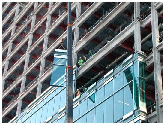
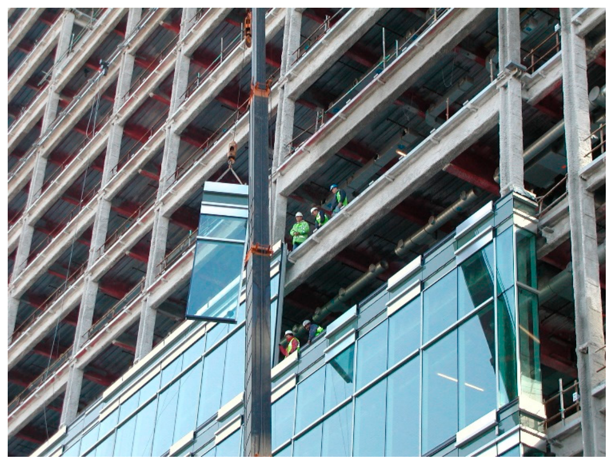
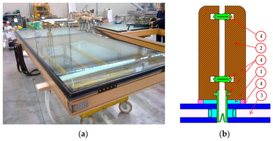
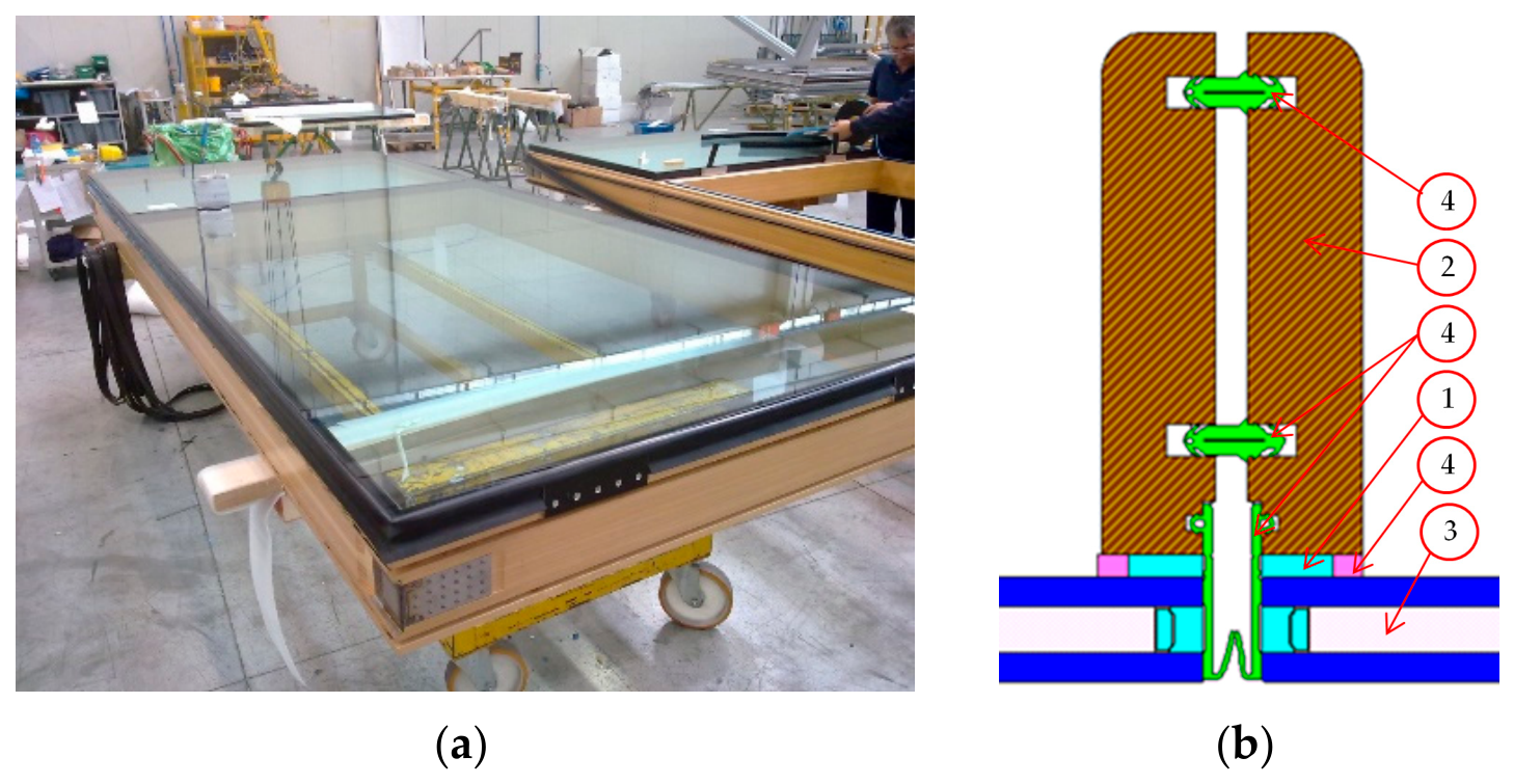
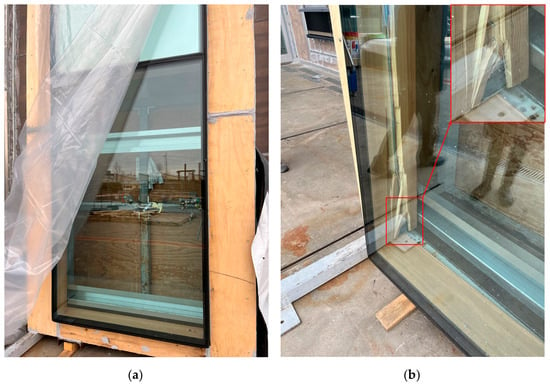
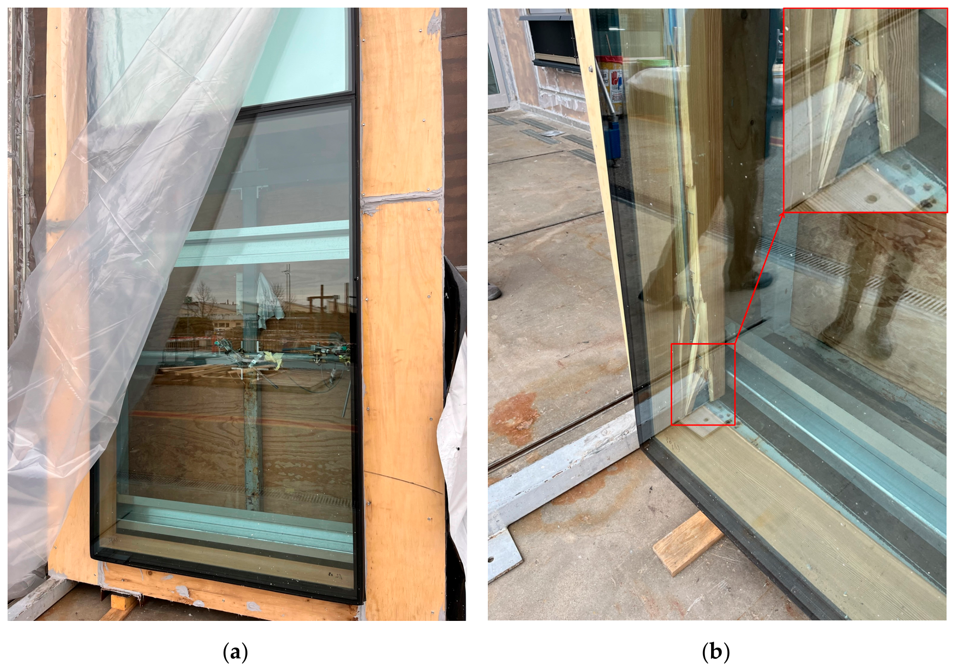
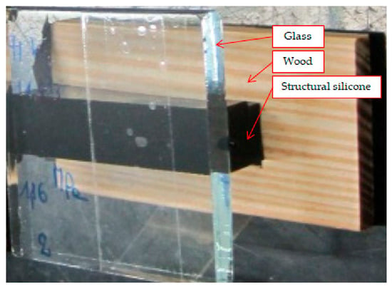
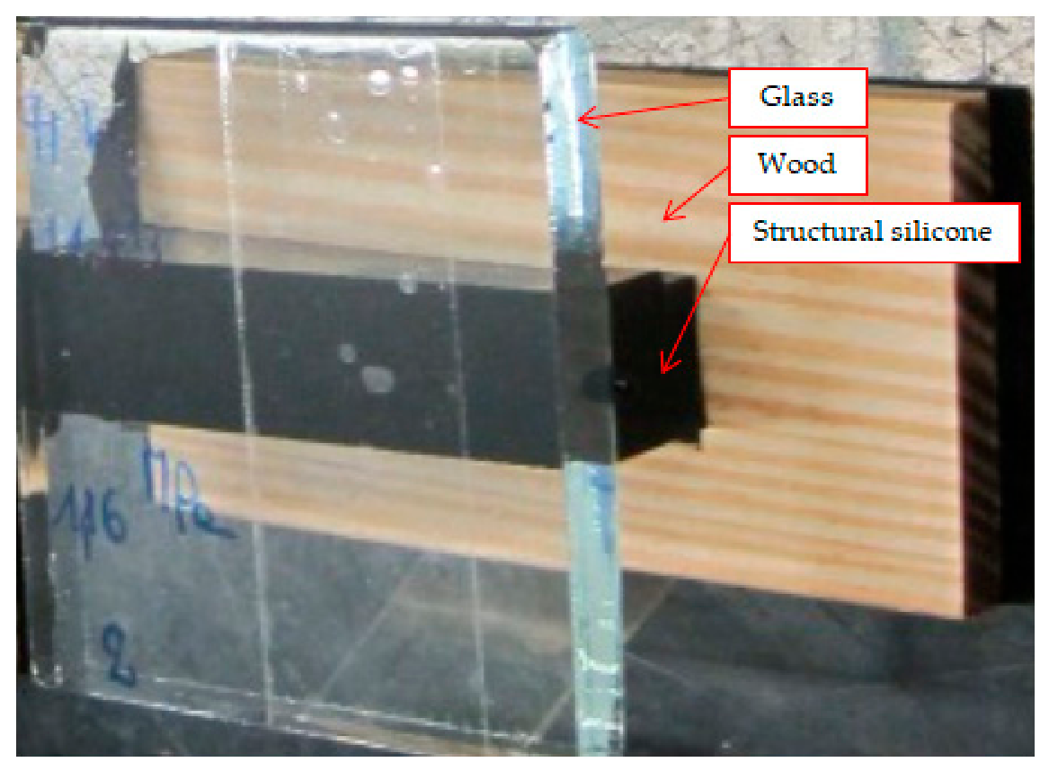
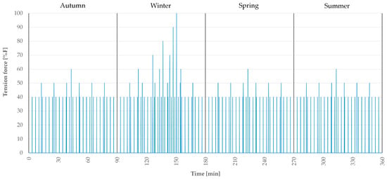
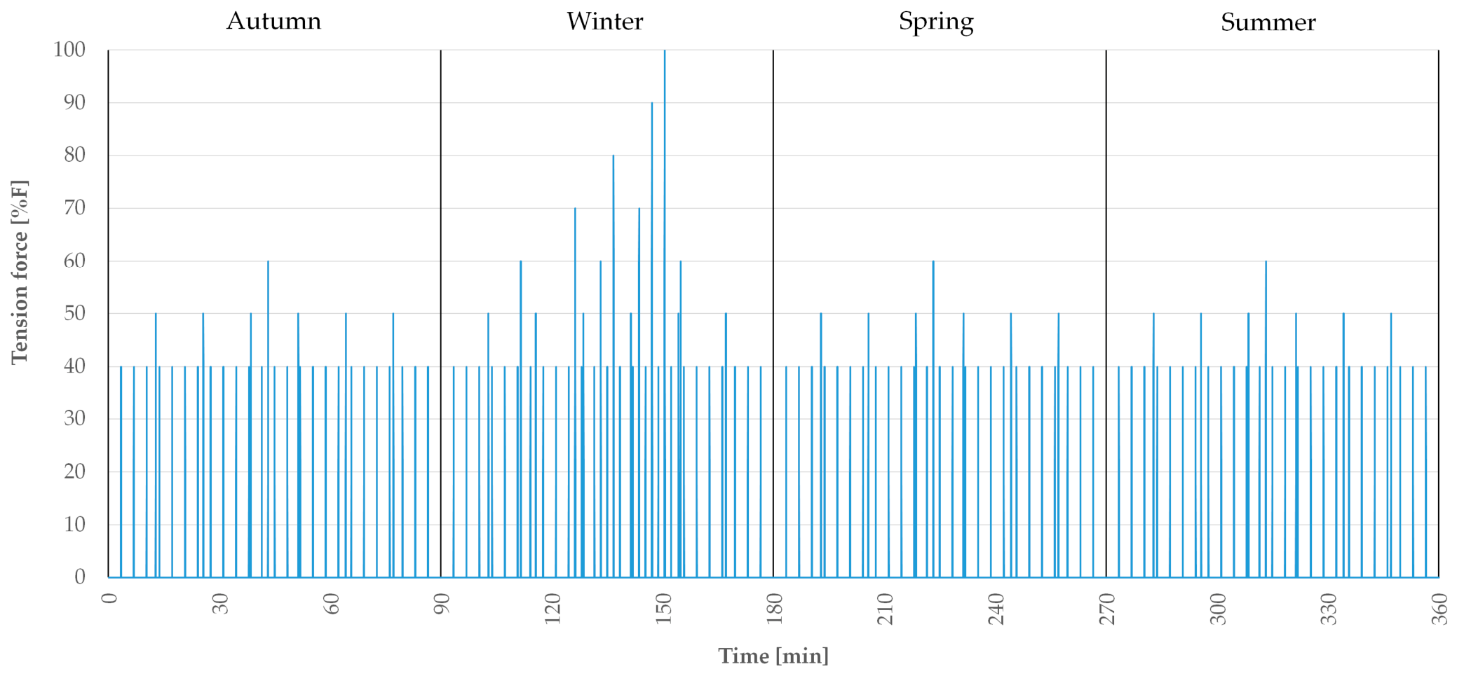
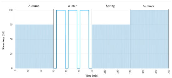
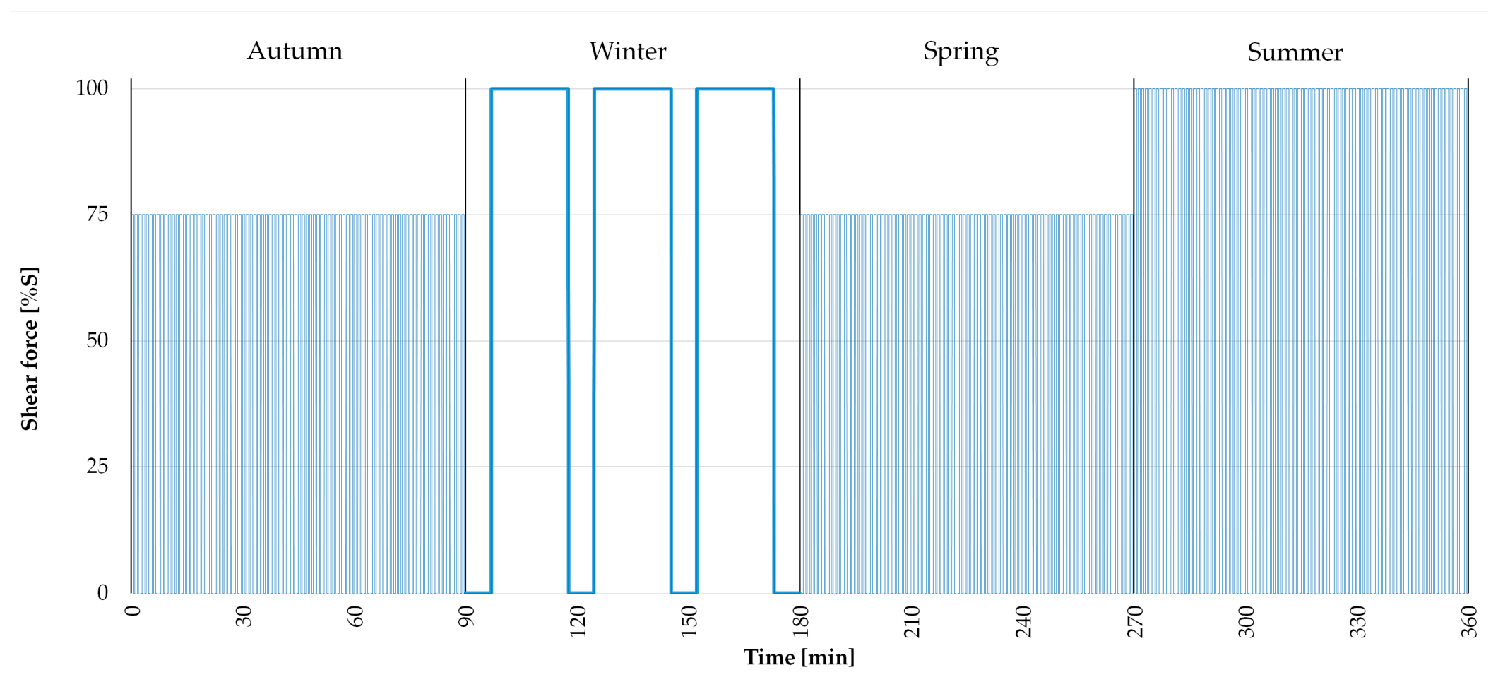
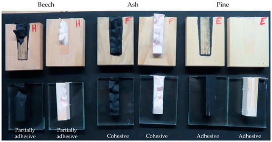
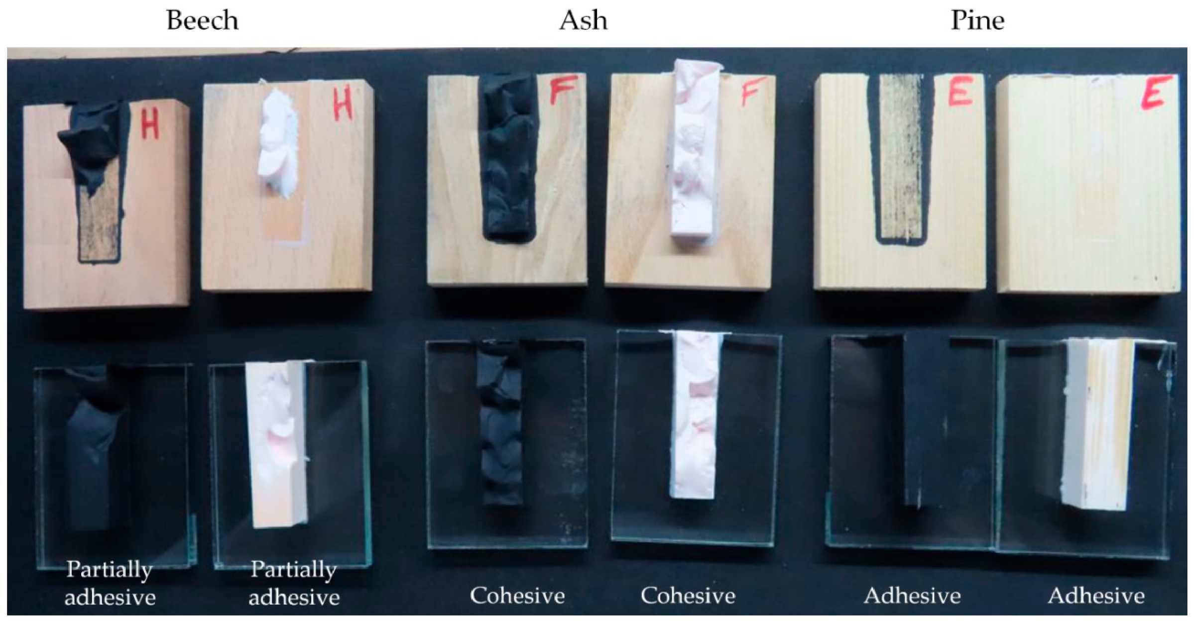
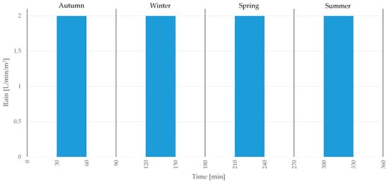
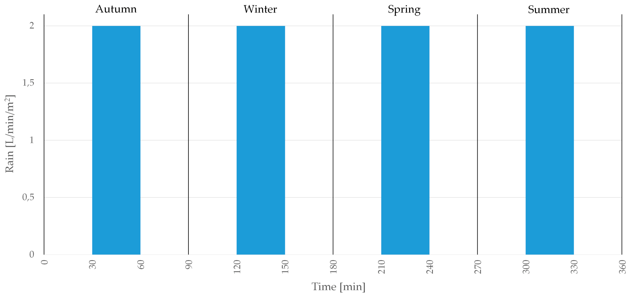
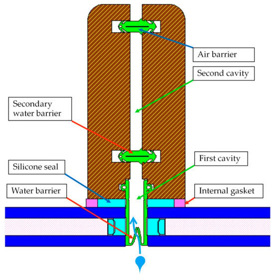
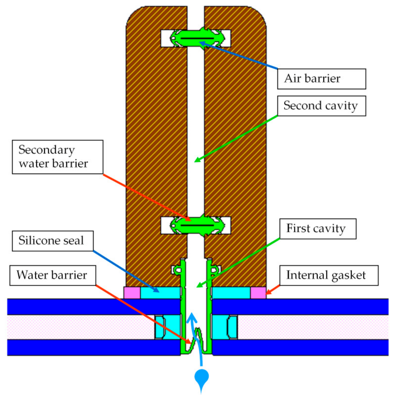
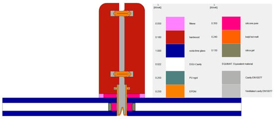
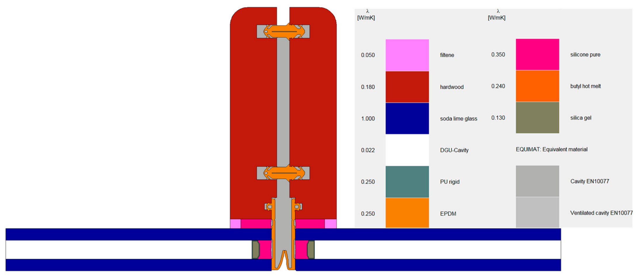
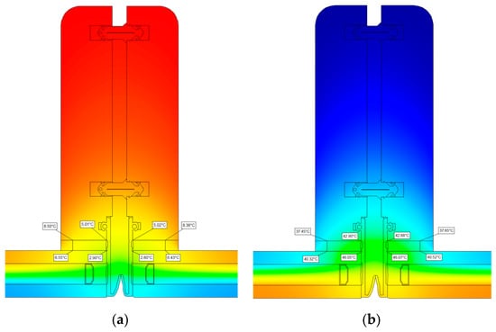
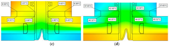
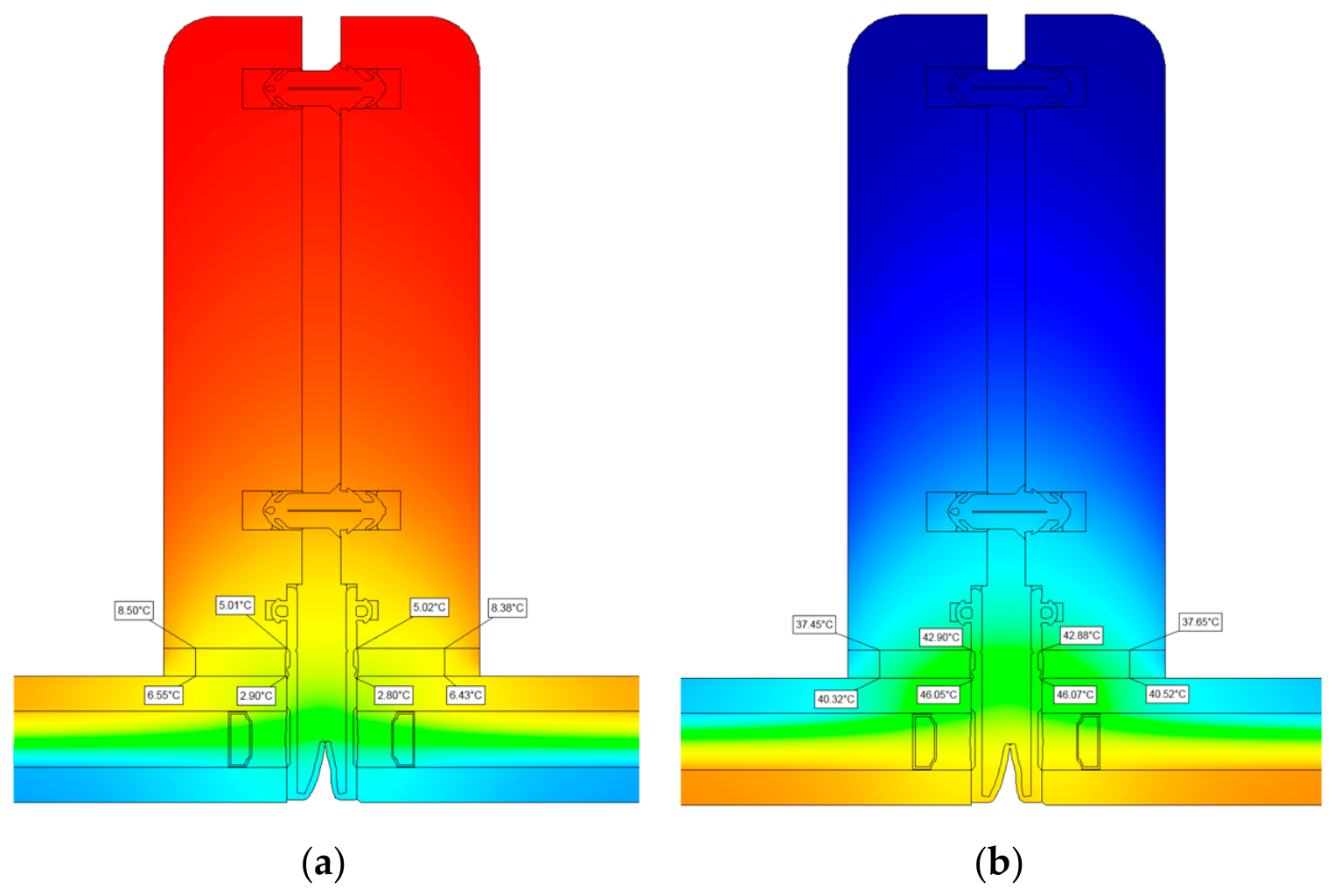
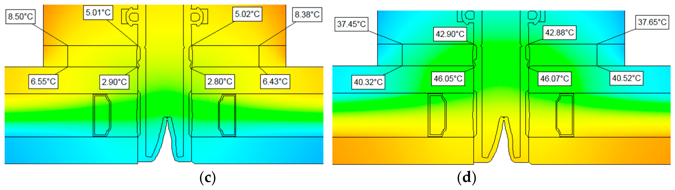
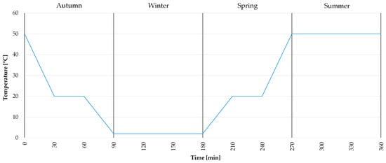
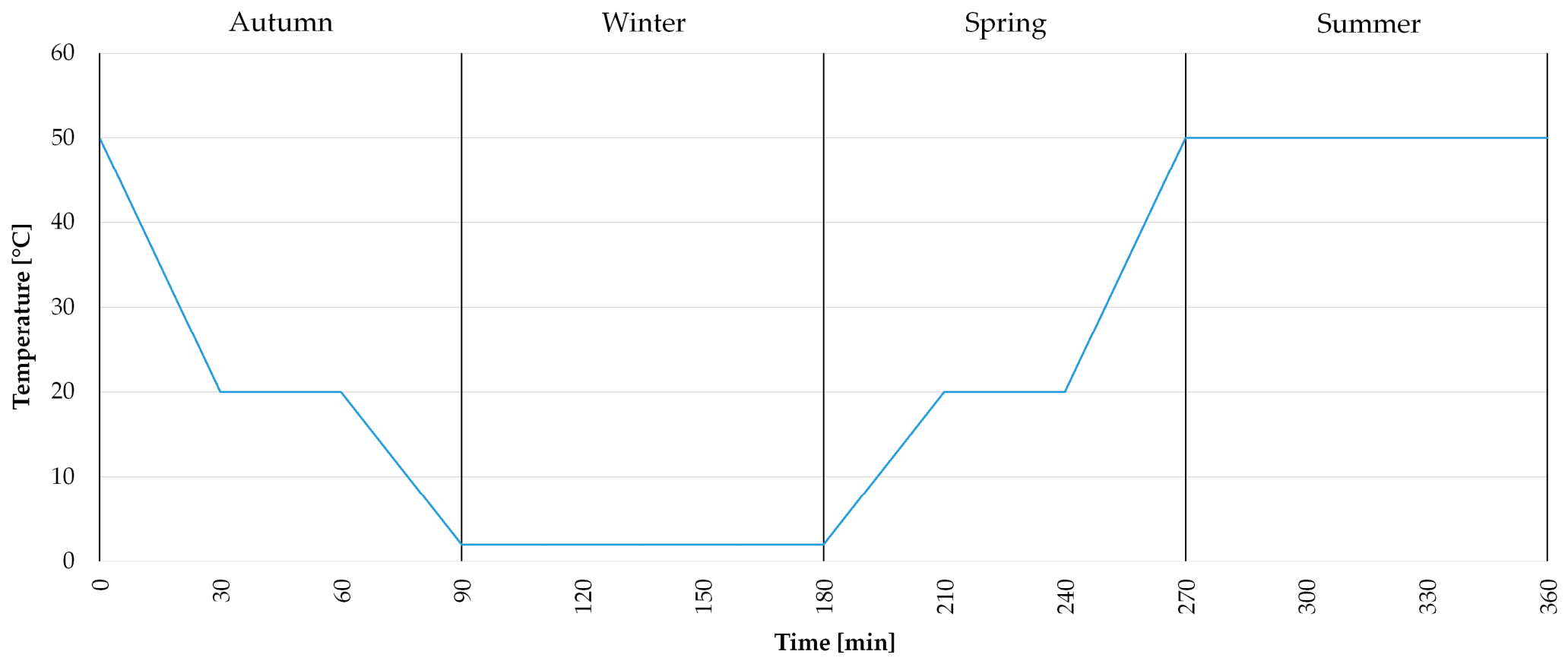
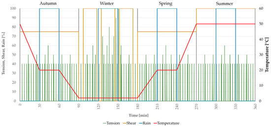
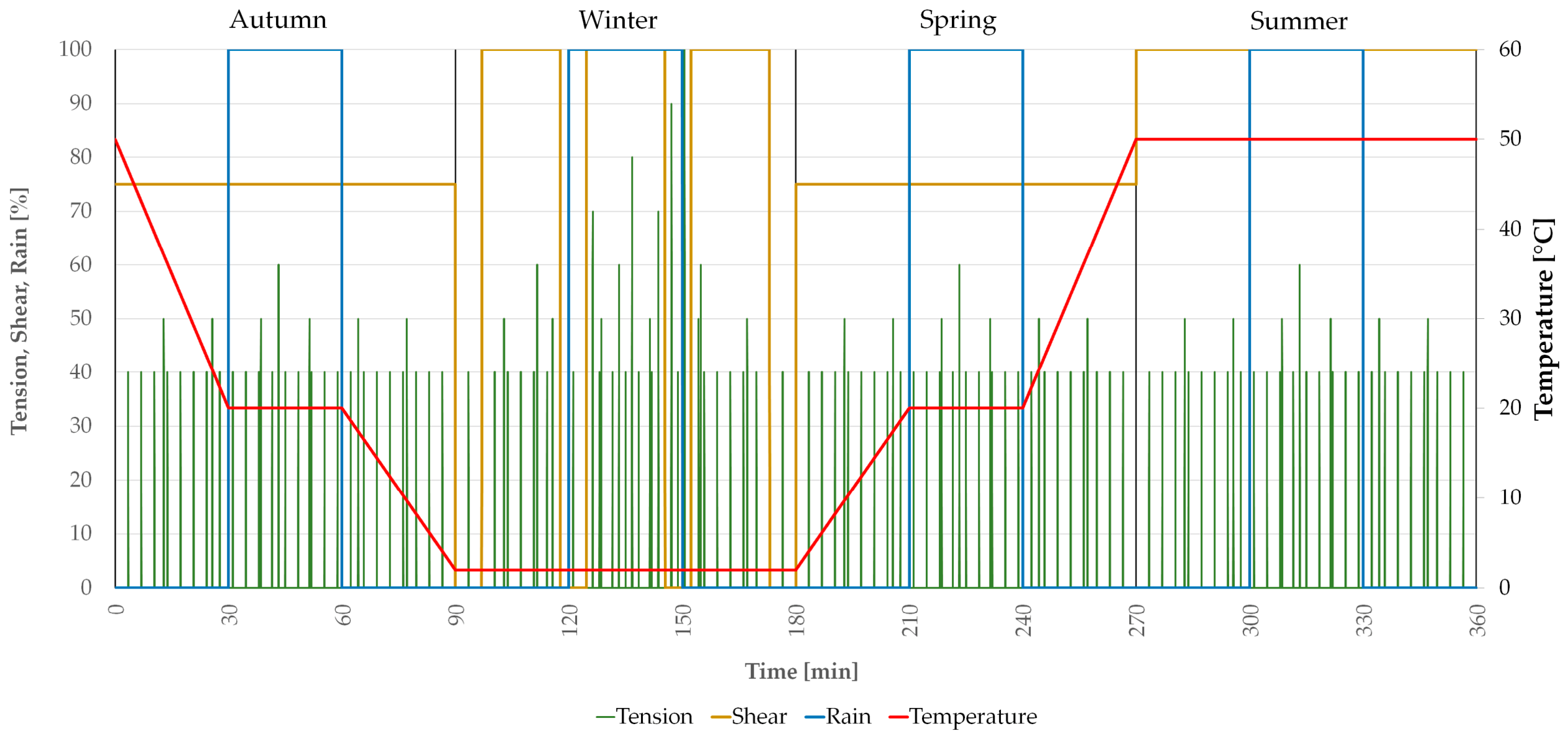
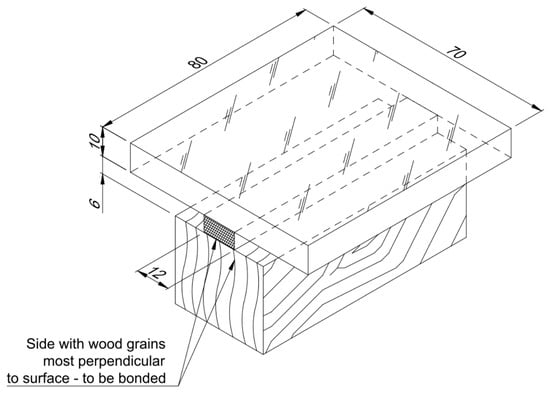
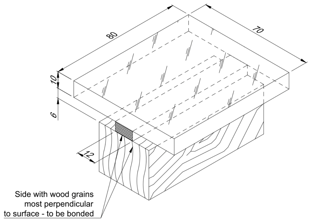
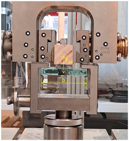
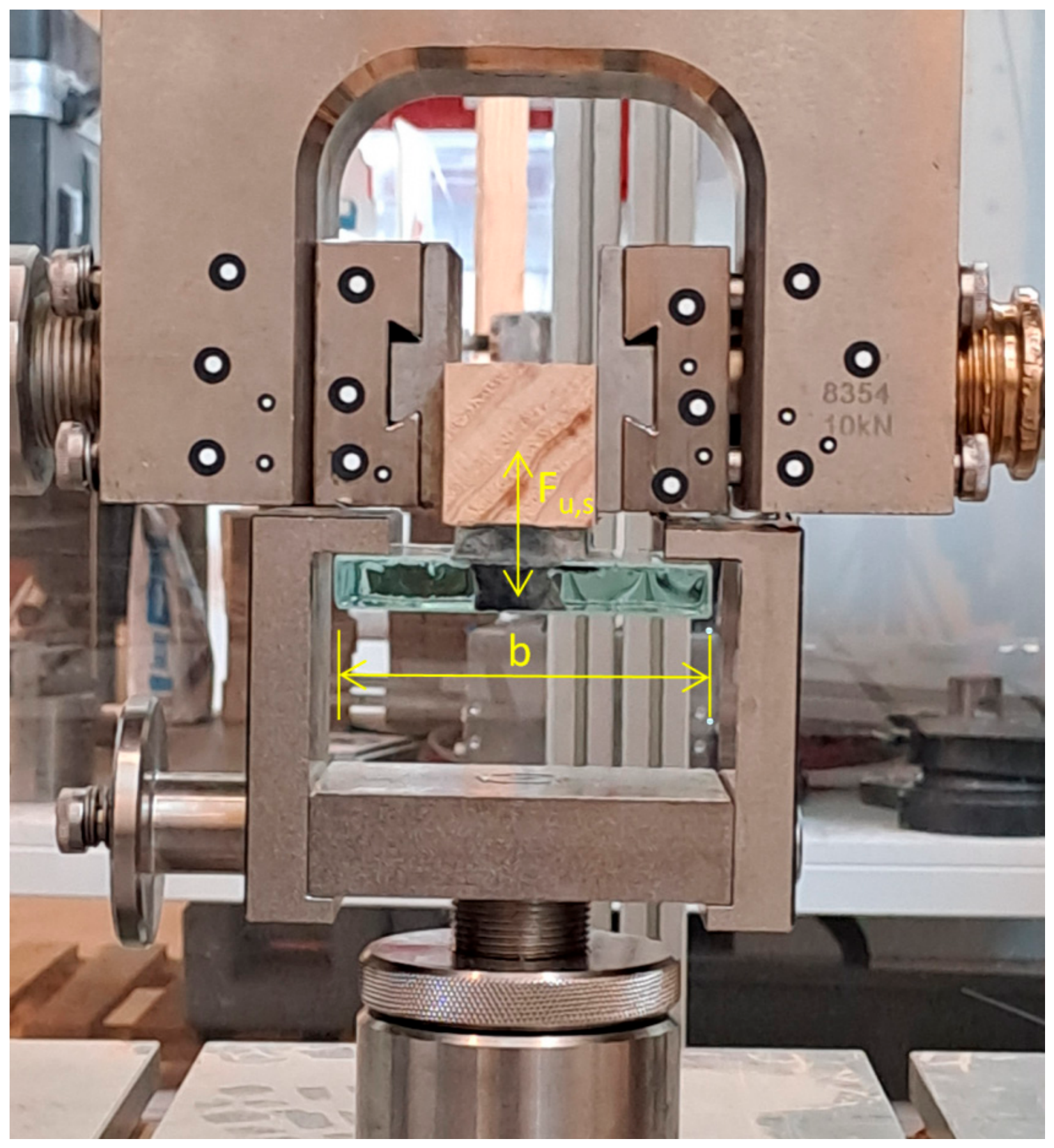
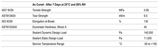
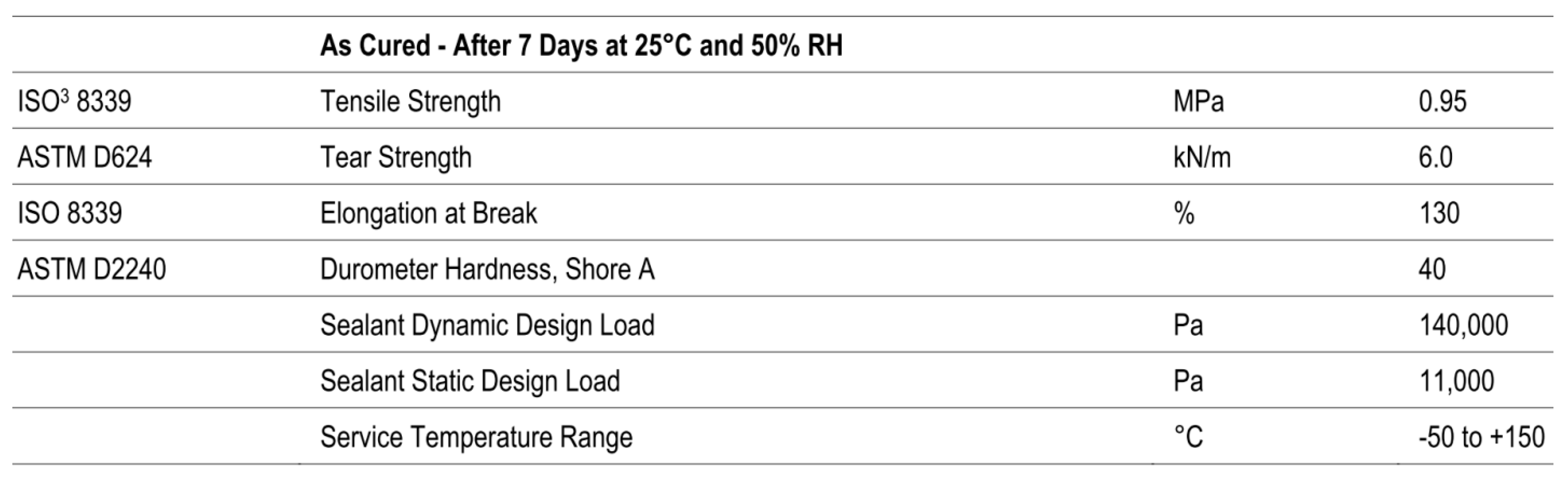
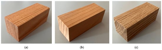
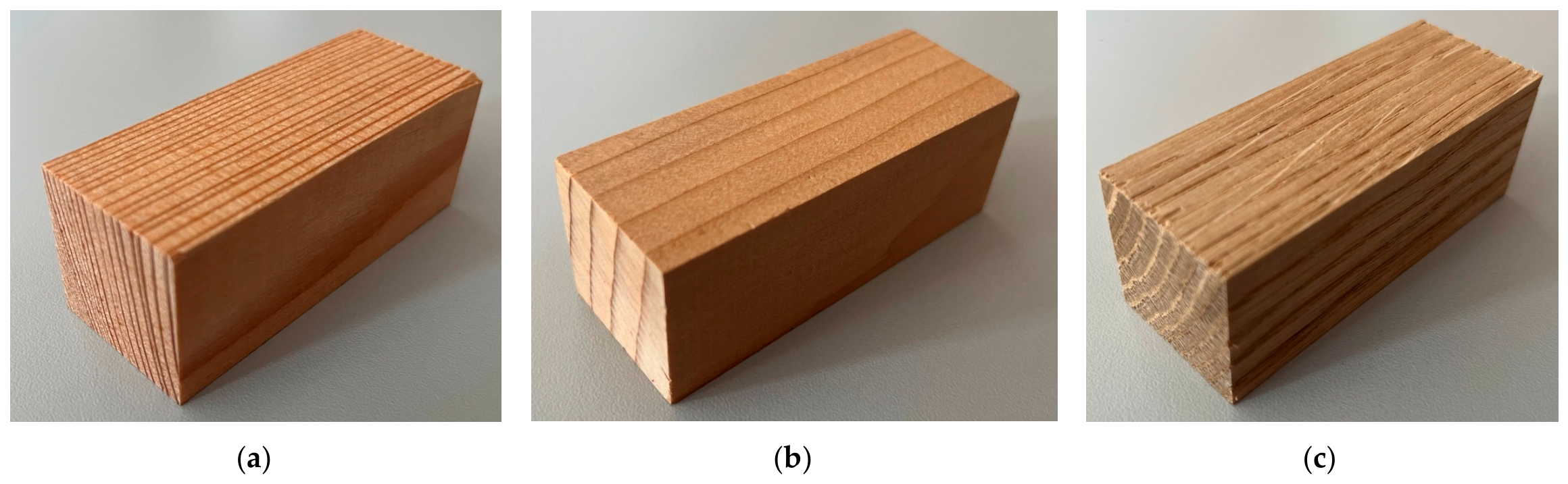
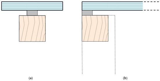
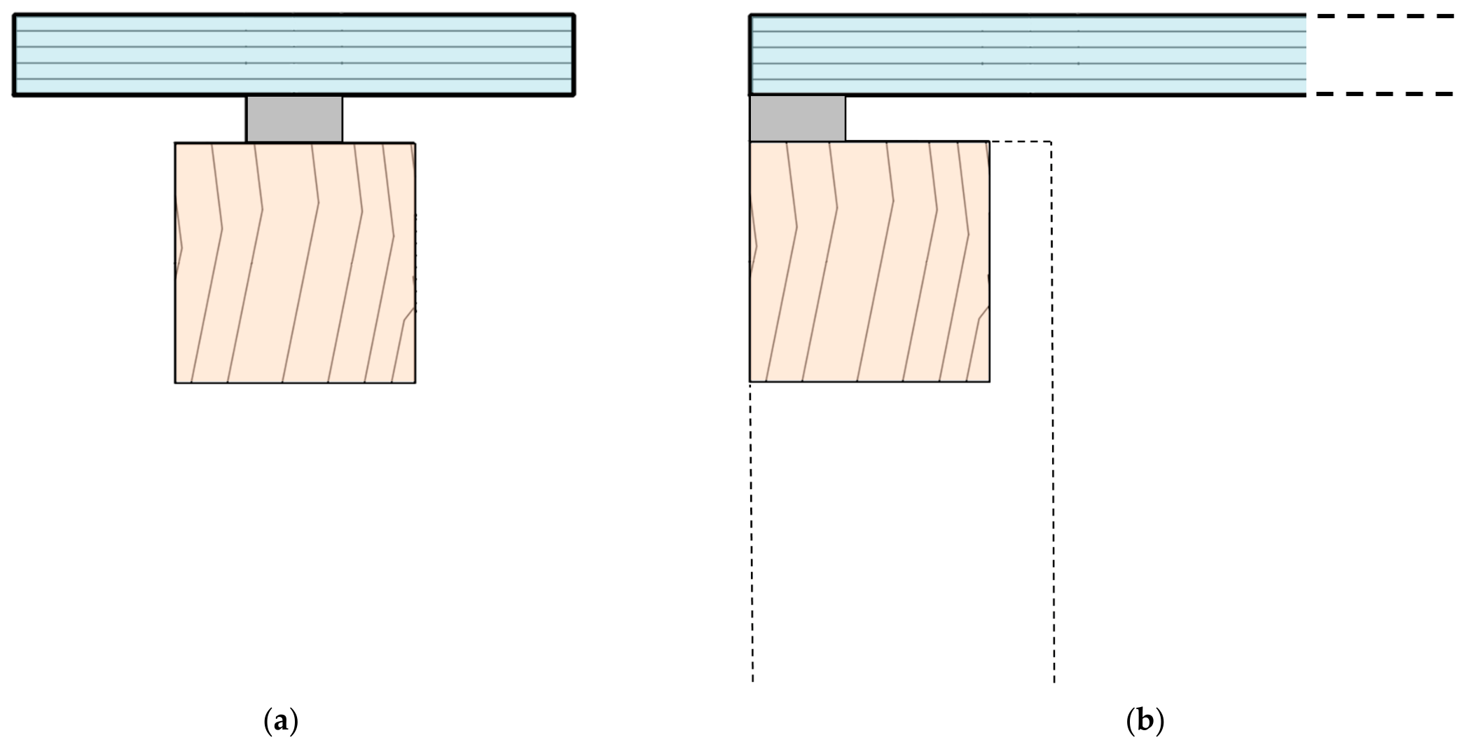
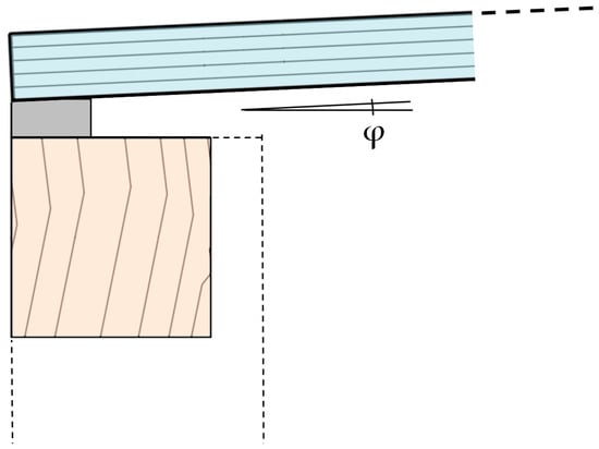
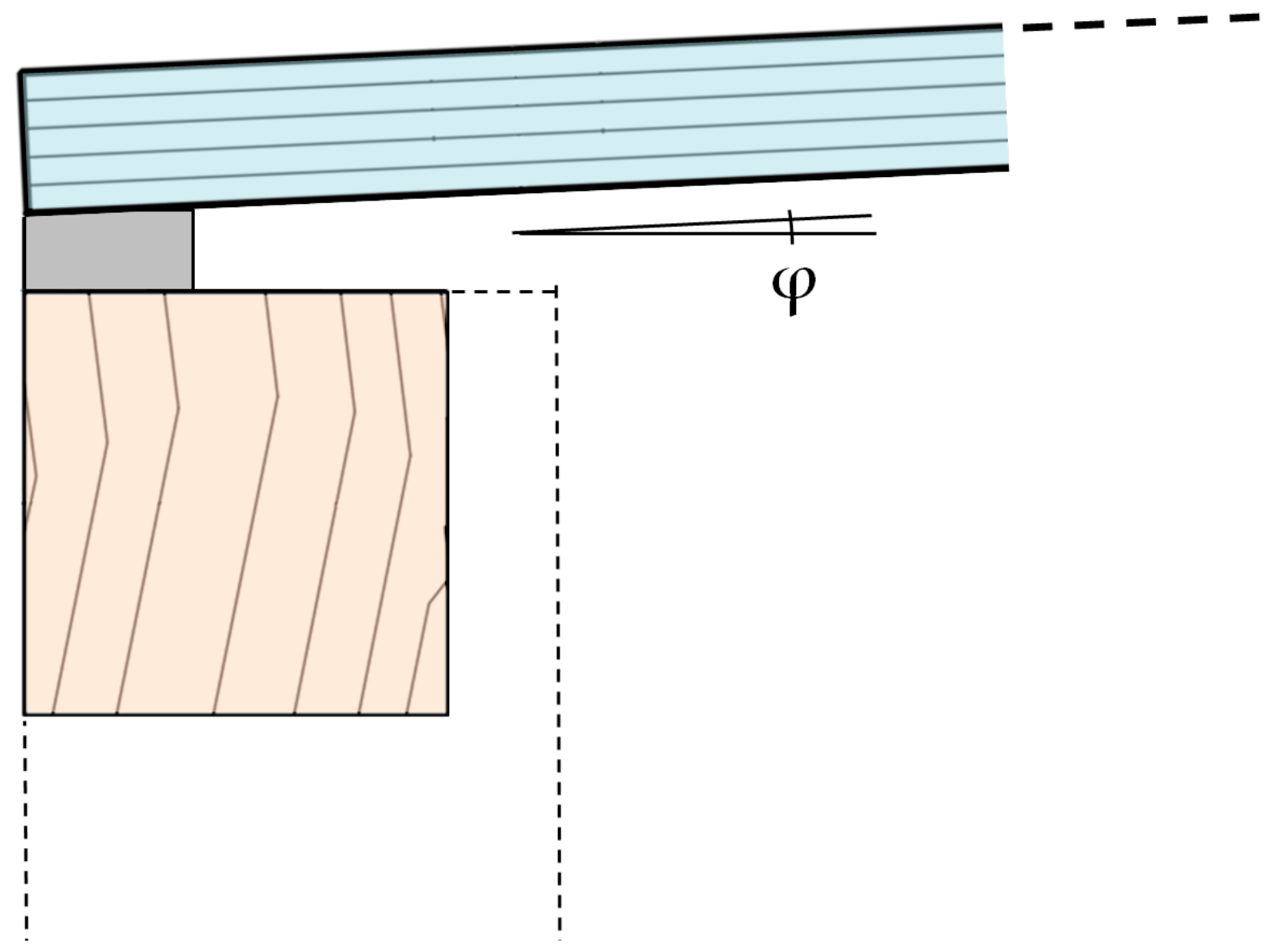
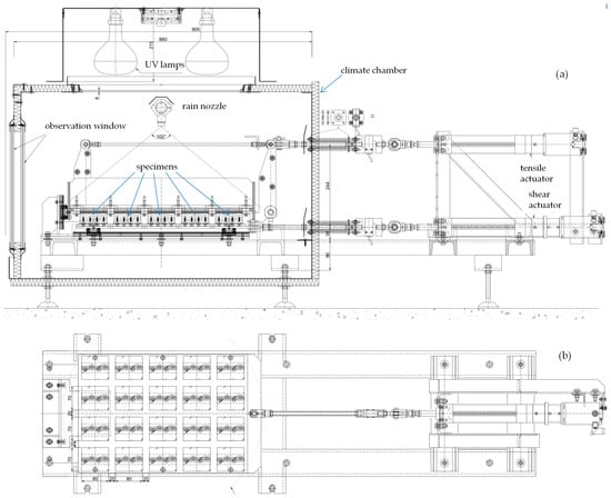
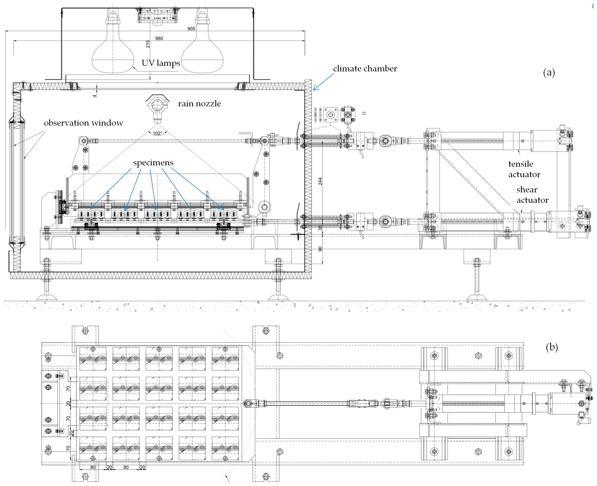
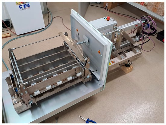
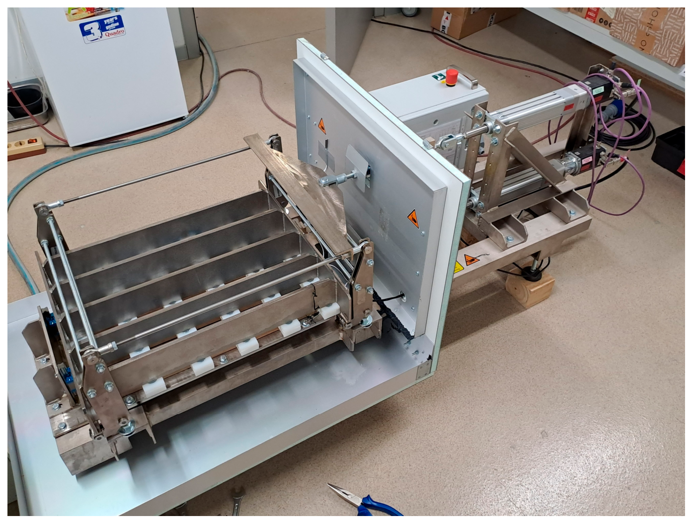
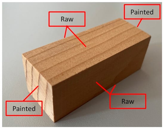
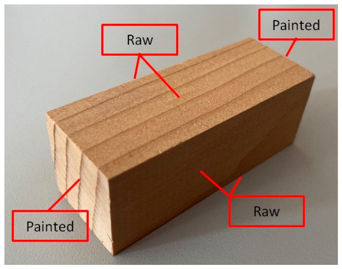
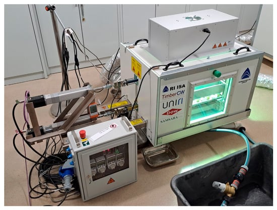
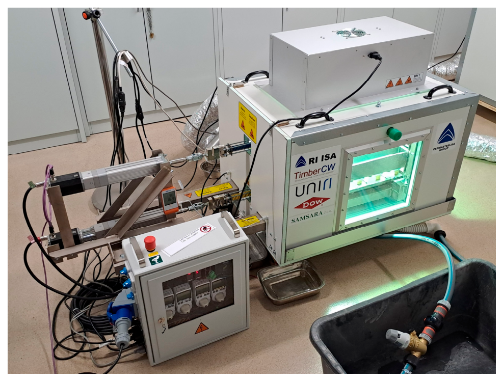
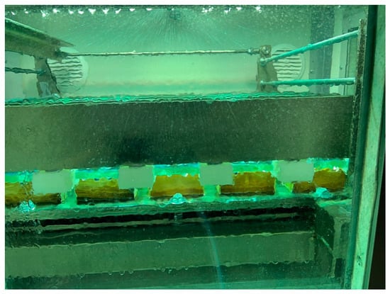
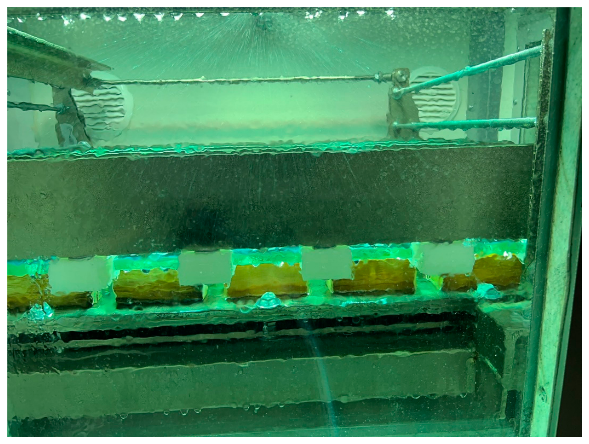
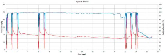
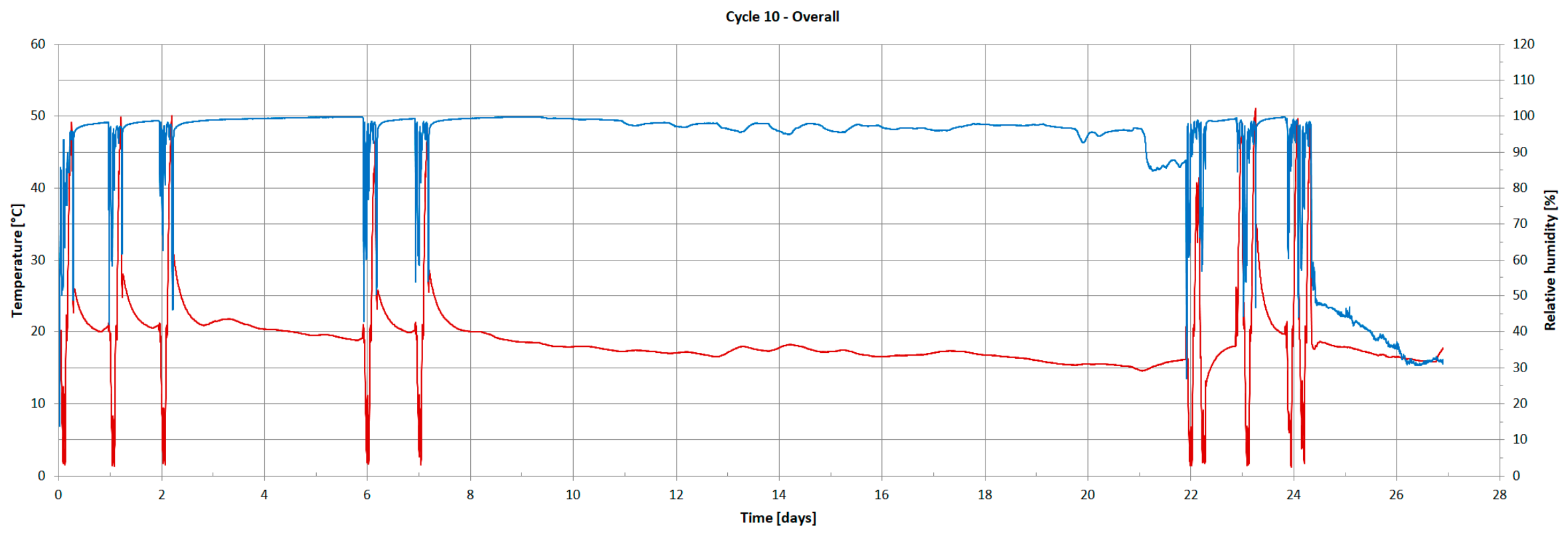
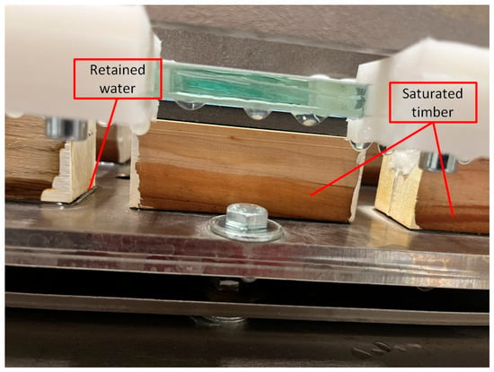
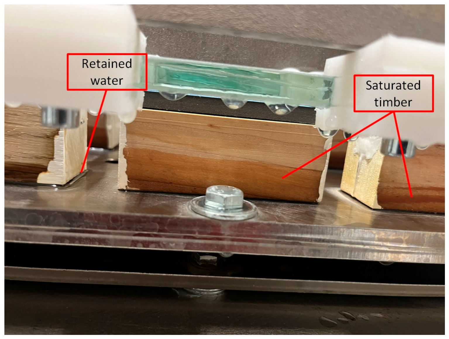
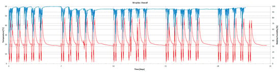
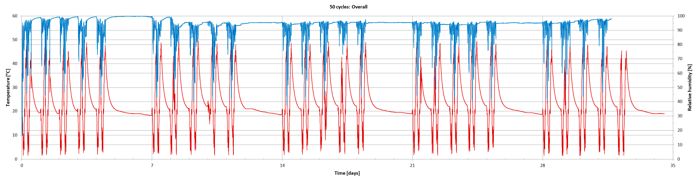
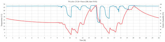
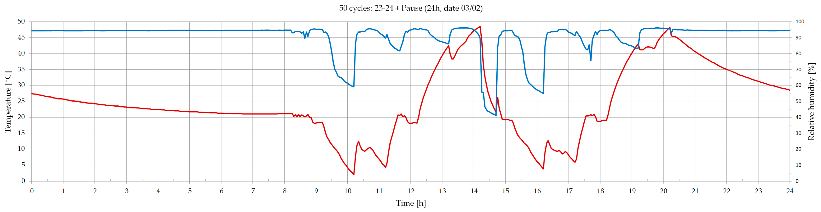
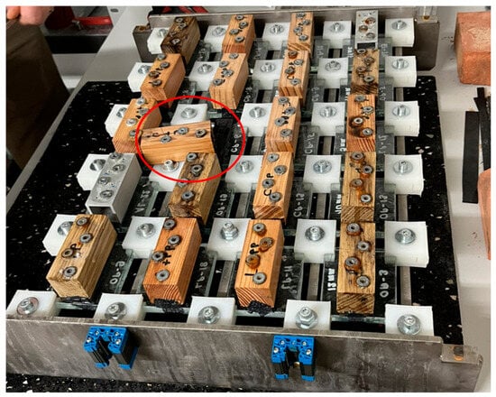
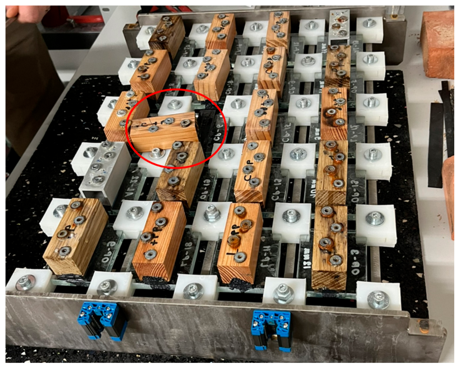
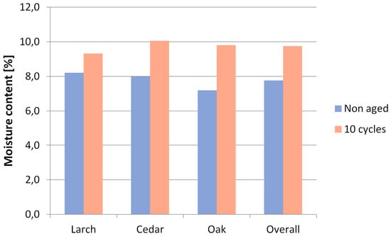
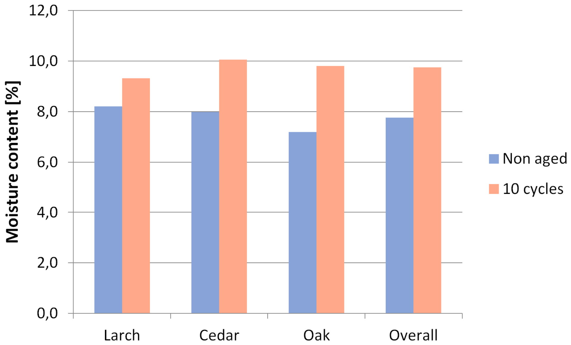
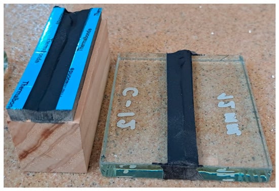
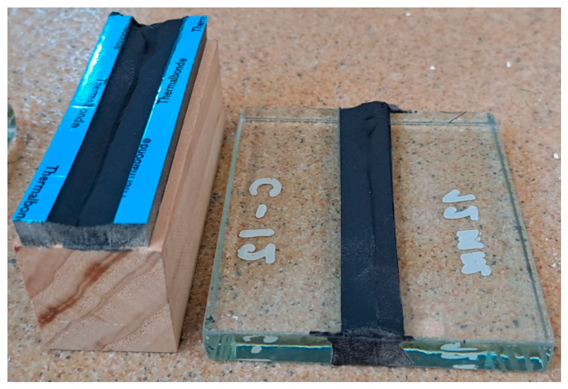
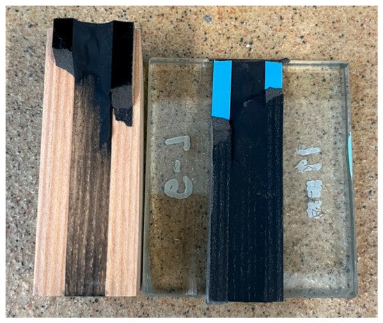
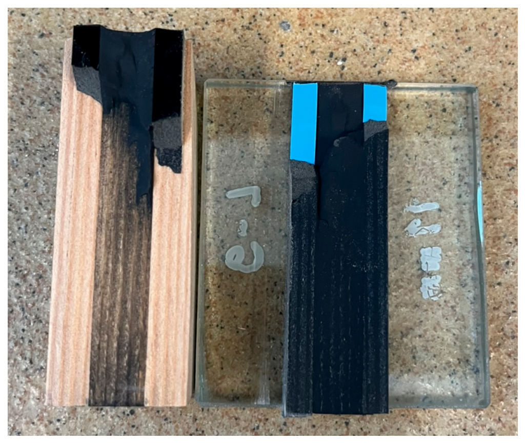
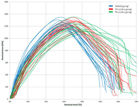
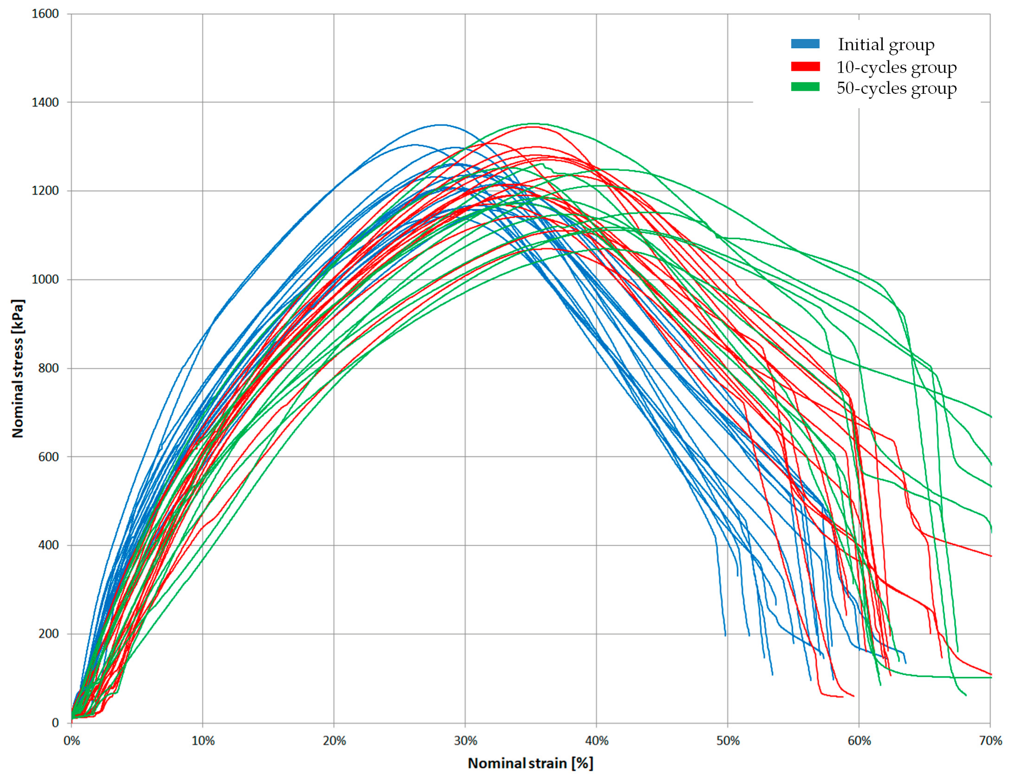
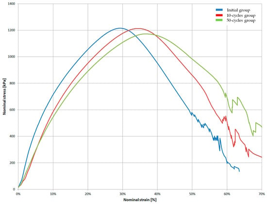
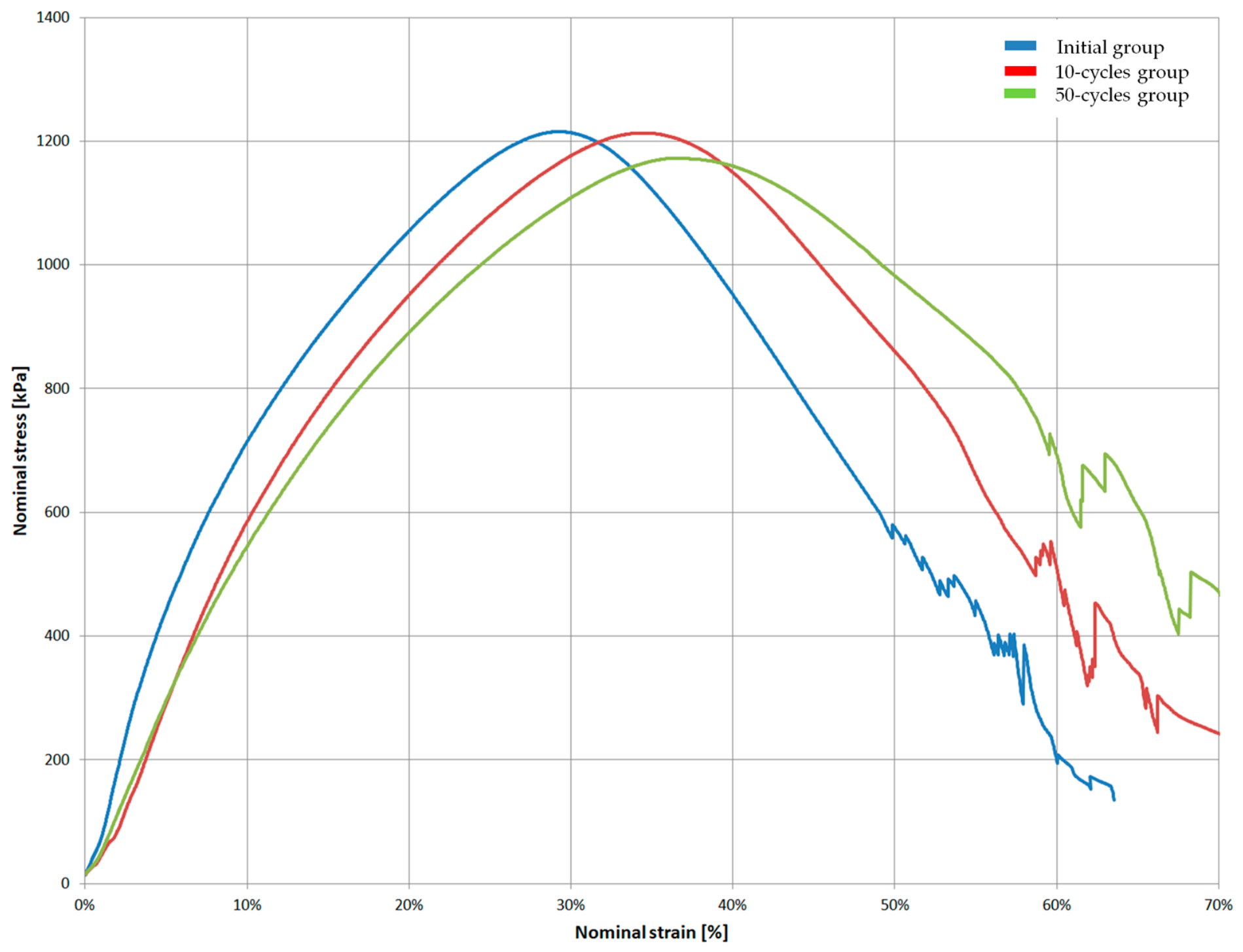

Disclaimer/Publisher’s Note: The statements, opinions and data contained in all publications are solely those of the individual author(s) and contributor(s) and not of MDPI and/or the editor(s). MDPI and/or the editor(s) disclaim responsibility for any injury to people or property resulting from any ideas, methods, instructions or products referred to in the content. |
© 2026 by the authors. Licensee MDPI, Basel, Switzerland. This article is an open access article distributed under the terms and conditions of the Creative Commons Attribution (CC BY) license.