


Abstract
Early-stage architectural design is still dominated by hand-drawn 2D floor-plan sketches, and converting these sketches into object-based Building Information Modeling (BIM) models remains a manual bottleneck that delays downstream simulation, costing, and coordination. Recent advances in multimodal artificial intelligence (vision-language models, code-generating large language models) and visual programming for BIM (Dynamo, Grasshopper, Refinery) have not yet been unified. Objective: We present and empirically evaluate a semi-automatic framework in which a vision-language model (VLM) emits executable visual-programming code (Dynamo-compatible DesignScript) that is wrapped into a node graph and executed in Dynamo to drive Revit, producing native BIM elements; the IFC export is independently validated in BlenderBIM as a visual sanity check. This is a proof-of-concept evaluation (n = 5 case studies), not a claim of production-scale deployment. Methods: The seven-module pipeline (sketch input, preprocessing, VLM interpretation, code-to-graph translation, Dynamo + Revit execution, IFC export with a BlenderBIM sanity check, and human-in-the-loop review with a feedback loop) is formalized mathematically—a line-sharpness function, a probabilistic AI-success model, and a closed-form architect-effort expression—and evaluated on five case studies (a Medipol student sketch, a public RPLAN sample, a tablet-drawn two-story house, a CubiCasa5K sample, and a real Istanbul apartment) against three baselines: a CNN recognizer (MuraNet), a JSON-emitting LLM pipeline (Sketch2BIM), and a hand-coded visual-programming framework. The primary VLM is Qwen-VL 9B (open-weight, Apache 2.0); GPT-4V and Claude 3.5 Sonnet are ablated on Case A only as closed-weight sensitivity checks. Results: Across the five cases, the framework achieves wall/opening F1 of 0.84–0.91 (mean 0.88), IFC schema validity of 100% in every case, a 56–61% reduction in time-to-editable-BIM, and 58–74% fewer architect edits than fully manual modeling, outperforming all three baselines on the architect-edits-required metric. The closed-form model predicts a 72% effort reduction under nominal parameters but overestimates the observed 56–61% by 11–16 percentage points; once the empirically observed architect-edit time is substituted, the calibrated model matches the observed range. Numbers are means over three runs per case. Conclusions: Unifying multimodal AI code generation with visual programming for BIM produces a more robust, editable sketch-to-BIM pipeline than the JSON-schema approaches in the current literature. Caveat: the evidence is a proof-of-concept scale (n = 5); broader validation (≥20 cases, cross-practice) is a key objective for future research.
1. Introduction
Early-stage architectural design is dominated by hand-drawn 2D floor-plan sketches. In our pedagogical and professional experience at Istanbul Medipol University, we observe that even in highly digitized practices, architects still default to paper and pencil for rapid ideation; they communicate design ideas on A4 paper with an HB pencil, with informal annotations such as room names (“salon”, “WC”), dimension hints, and arrows pointing to design intentions [1,2]. The translation of these sketches into object-based Building Information Modeling (BIM) models is a manual, time-consuming bottleneck: a junior architect typically requires 6–12 h to convert a single A4 sketch into a Revit model with walls, doors, windows, and rooms [1,2]. The downstream pipeline—structural analysis, energy simulation, cost estimation, code compliance—all wait on the BIM model (Figure 1).
Figure 1.
The problem this paper addresses (A) and the process it proposes (B). Manual conversion of a hand-drawn sketch into an object-based BIM model is a 6–12 h, error-prone, non-reproducible bottleneck (A); the seven-module framework detailed in Section 3.1 replaces it with AI-authored visual programming (Dynamo + Revit) plus a short human review (B). See Section 1 and Section 3.1.
1.1. The Opportunity Created by Multimodal AI
The 2023–2026 wave of large language models (LLMs) and vision-language models (VLMs) has produced a new generation of tools that can read images, understand spatial layouts, and emit structured text or code [3,4,5,6,7,8,9,10,11,12,13]. Of particular relevance to architecture is the emergence of:
- Multimodal LLMs (MLLMs) such as GPT-4V, Claude 3.5 Sonnet, and Qwen-VL that can read a floor-plan sketch and answer questions about its contents [3,4]. We use Qwen-VL 9B as the primary model in all reported runs (open-weight, Apache 2.0; reproducible weights listed in Appendix C) because it is the only candidate in this family that is open-weight at the time of writing; GPT-4V and Claude 3.5 Sonnet are ablated as closed-weight alternatives on Case A only and reported in Appendix E for sensitivity, not as primary runs.
- Code-generating LLMs that can emit executable code in response to a natural-language specification. Recent work has shown that LLMs can be embedded into BIM authoring tools (Dynamo, Revit, Vectorworks) as copilots [4,5], and that multi-agent MLLM pipelines can convert a hand-drawn sketch into a 3D BIM model [14].
- Domain-specific LLMs for BIM such as Qwen-BIM [8], fine-tuned on BIM corpora, and BIM-specific agents that use the Model Context Protocol (MCP) to query IFC files [9].
- LLM-driven code-compliance checking that uses retrieval-augmented generation (RAG) over building codes [10,13].
These advances (Table 1) suggest that the manual conversion of a sketch to a BIM model can be semi-automated. Prior work, however, has one of two limitations:
Table 1.
Tools and model families referenced in Section 1.1, grouped by role in the pipeline.
1. The AI emits a JSON schema, not code. The schema is then post-processed by a separate tool (Revit API, IfcOpenShell). This separation has a known weakness: the AI is unaware of the visual-programming paradigm that BIM practitioners actually use [5,8,14].
2. The visual-programming graph is hand-coded. Practitioners write Dynamo or Grasshopper scripts to drive Revit, but no AI assistance is provided for the script-writing step itself [15].
1.2. The Opportunity Created by Visual Programming
In parallel, the BIM authoring community has adopted visual programming as the dominant paradigm for parametric and generative design. Visual-programming tools—Dynamo, Grasshopper, Refinery, Rhino.Inside—allow architects to build complex BIM workflows by connecting nodes on a canvas, rather than by writing imperative code [15]. Visual programming has also been examined as a medium for teaching computational design concepts [15], while point-cloud-based scan-to-BIM workflows have automated the creation of BIM elements from as-built data [16,17].
A key insight is that the intermediate representation matters. Unlike Ratul et al. [14] whose sketch-to-BIM pipeline we initially intended to replicate in our lab, we found that direct VLM-to-JSON generation is too brittle for production workflows, forcing the AI to invent a schema no BIM tool understands natively. In contrast, code—specifically, the visual-programming language (DesignScript) of the target tool—maps to a representation the practitioner already uses. The architect sees a node graph, can edit it, and can re-run it. The same insight has been articulated in the broader LLM-for-code literature: the LLM should emit code in a language the human already speaks.
1.3. Research Question and Contribution
The research question that motivates this paper is: Can a multimodal AI system, paired with a visual-programming bridge for BIM and an independent IFC viewer, semi-automatically convert hand-drawn 2D sketches into object-based BIM models with a measurable reduction in architect effort?
We answer this question with the following primary and secondary contributions:
1. Primary contribution: The visual-programming bridge—A new framework (Section 3) in which a VLM emits executable visual-programming code (DesignScript) that is wrapped into a node graph and executed in Dynamo + Revit. This intermediate representation serves as an editable bridge, replacing direct JSON-schema generation. The output is validated independently in BlenderBIM.
2. Supporting mathematical formalization (Section 3.2) of the pipeline: (i) a line-sharpness function that quantifies the preprocessing gain, (ii) a probabilistic model of the AI’s success as a function of sketch complexity, and (iii) a closed-form expression for the expected reduction in architect effort.
3. A prompt-engineering protocol for the VLM, with concrete prompt templates and worked examples for the Dynamo/Revit/BlenderBIM workflow.
4. An empirical evaluation on five case studies (Section 4) with five metrics: wall/opening F1, IFC schema validity, time to editable BIM, architect edits required, and visual-programming execution time.
Novelty relative to the closest prior work. To make the differentiation explicit: unlike Ratul et al. [14], whose Sketch2BIM pipeline emits a JSON schema that a separate tool must post-process, our framework emits executable visual-programming code directly, so the intermediate artifact is one that BIM practitioners can inspect, edit, and re-run. Unlike Jeong et al. [18,19], whose visual-programming graphs are hand-coded with no AI assistance, our VLM authors the Dynamo graph automatically from a hand-drawn sketch. And unlike CNN-based recognizers such as MuraNet [20], which output a wall/door/window classification that still requires a separate, hand-engineered conversion step to reach BIM, our pipeline produces native Revit elements directly. This combination—AI-authored (not hand-coded) executable code (not a JSON schema) that drives native BIM authoring (not classification alone)—is, to our knowledge, not previously demonstrated in the sketch-to-BIM literature (Section 2.6 details the three specific gaps in the literature that this closes).
The paper is structured as follows. Section 2 reviews the literature, presents the PRISMA 2020 systematic search that grounds the study, and identifies the gap our work addresses. Section 3 presents the framework with its mathematical formalization, the prompt template, and a worked example of a Dynamo graph produced by the AI. Section 4 reports the case-study evaluation, the prompt-and-output examples, and the comparison with baselines. Section 5 discusses threats to validity and future directions. Section 6 concludes.
The framework, all code, and all case studies are released under Apache 2.0 (code) and CC-BY 4.0 (data), available from the corresponding author upon reasonable request, to encourage reproduction and extension (see Appendix C for code, weights, dataset, and Docker details).
2. Related Work
2.1. Systematic Search Protocol (PRISMA 2020)
We conducted a PRISMA 2020 systematic search of the literature on sketch-to-BIM conversion, with an explicit focus on the intersection of (a) sketch recognition, (b) visual programming, and (c) BIM authoring. The search was performed on 2026-06-28 across three open-access databases—OpenAlex (primary), Semantic Scholar (cross-check), and arXiv (pre-prints)—using six query families:
- Q1: (“sketch-to-BIM” OR “sketch to BIM” OR “hand-drawn BIM” OR “sketch modeling”) AND (“Dynamo” OR “DesignScript” OR “visual programming” OR “Refinery” OR “Grasshopper” OR “Rhino.Inside”)
- Q2: (“Dynamo” OR “DesignScript”) AND (“Revit” OR “BIM” OR “IFC” OR “BIM authoring”) AND (“automatic” OR “generative” OR “AI” OR “machine learning”)
- Q3: (“BlenderBIM” OR “IfcOpenShell”) AND (“sketch” OR “floor plan” OR “BIM authoring” OR “IFC generation”)
- Q4: (“Grasshopper” OR “Rhino.Inside.Revit”) AND (“floor plan” OR “BIM” OR “generative design”) AND (“AI” OR “LLM” OR “neural”)
- Q5: (“LLM” OR “GPT” OR “Copilot”) AND (“Revit API” OR “Dynamo” OR “DesignScript” OR “IFC” OR “BIM authoring tool”)
- Q6: (“code generation” OR “program synthesis”) AND (“BIM” OR “Revit” OR “IFC” OR “Building Information Modeling”)
PRISMA 2020 funnel (Figure 2; Table 2); Appendix D. Records were retrieved in two waves—a broader v0.1 baseline (n = 102, 8 June 2025) and a Dynamo-aware wave (n = 561 unique OpenAlex records, 28 June 2026, Q1–Q6)—and combined without duplication, since the two waves target distinct, non-overlapping DOI populations (see Table 2 for the full stage-by-stage rationale).
Figure 2.
PRISMA 2020 funnel. 561 records identified across Q1–Q6; 17 seed + 90 carryover = 124 corpus. See Section 2.1.
Table 2.
PRISMA 2020 stage counts (Section 2.1).
Reading. The Q1–Q6 queries are narrowly scoped to the sketch + visual-programming/BIM intersection; papers on sketch-to-BIM alone are re-introduced via the v0.1 carry-over, and visual-programming-only papers are excluded at full text (Table 2 gives the full per-stage rationale). Seventeen foundational software-artefact papers (Dynamo/DesignScript, IfcOpenShell/BlenderBIM, Qwen-BIM) are seeded manually and disclosed with a † prefix in the bibliography. The resulting 124-paper corpus is well above the PRISMA 2020 minimum of 30 and supports the bibliometric snapshot in Figure 3: CNN 28 (22.6%), LLM 25 (20.2%), Visual Programming 14 (11.3%), Transformer 12 (9.7%), Diffusion 11 (8.9%), GNN 8 (6.5%), Hybrid 6 (4.8%), GAN 5 (4.0%), Classical ML 5 (4.0%), Dataset 3 (2.4%), Rule-based 2 (1.6%), MLLM 2 (1.6%), VLM 2 (1.6%), Other 1 (0.8%), peaking in 2025 (32 papers). The Visual-Programming cluster is the smallest of the four major clusters but the one our framework directly extends.
Figure 3.
Method distribution over the 124-paper corpus. CNN 28 (22.6%), LLM 25 (20.2%), Visual Programming 14 (11.3%). See Section 2.1.
2.2. Cluster 1: Classical Sketch Recognition (Pre-2017)
Hand-engineered features and rule-based systems dominated the pre-deep-learning era. Wang et al. (2020) [21] and Surikov et al. (2020) [22] used classical machine learning (C4.5 decision trees, support vector machines) to recognize architectural objects in floor plans. Ravagli et al. (2019) [23] used deep text recognition in floor-plan images. These methods achieved precision in the 0.85–0.95 range on clean inputs but failed on rough student sketches, the input modality we target. The classical ML cluster in our corpus is small (five papers, 4.0%) and has been largely superseded by deep learning.
2.3. Cluster 2: Deep-Learning Floor-Plan Analysis (2017–2023)
The post-2017 wave was dominated by CNN-based methods. Segmentation-based approaches (MuraNet [20], ArchNetv2 [24], boundary-attention networks [25,26], row–column networks [27]) treat walls, doors, and windows as semantic-segmentation classes. Object-detection methods (ArchNet, WallNet, Faster R-CNN) frame the problem as object detection. GNN-based methods (Chen & Pan [28], Simonsen et al. [29], Di et al. [30], SE-VGAE [31]) treat the floor plan as a graph of rooms and walls. These methods achieve F1 in the 0.80–0.90 range on R3D (Rent3D, a public floor-plan dataset) and CubiCasa5K but do not output IFC natively. The conversion to IFC is a separate, hand-engineered step. A second limitation is regional bias: R3D and CubiCasa5K over-represent North American and Northern European housing, with reported F1 drops of 5–10 percentage points on typical Istanbul Mediterranean apartments.
2.4. Cluster 3: LLM/MLLM-Based BIM Authoring (2023–2026)
The LLM wave produced 25 papers (20.2%) in our corpus. DeFazio et al. (2024) [3] showed that vision-language models can parse floor-plan maps. Du et al. (2024) [4] proposed an LLM-based copilot for BIM authoring tools. Hellin et al. (2026) [6] described an LLM agent for adaptive BIM information extraction. Lin et al. (2026) [8] developed Qwen-BIM, a domain-specific LLM for BIM. Nithyanantham et al. (2025) [9] introduced MCP4IFC, an LLM-with-MCP approach for IFC queries. Madireddy et al. (2025) [10] used LLMs for code-compliance checking in BIM. Sahraoui et al. (2025) [32] integrated Generative AI in BIM education. The most directly relevant prior work is Ratul et al. (2025) [14], who proposed a multi-agent MLLM pipeline (Sketch2BIM) that converts hand-drawn sketches to 3D BIM models. The Sketch2BIM pipeline, however, emits a JSON schema that is post-processed by a separate tool—it does not use visual programming.
2.5. Cluster 4: Visual Programming for BIM (The Central Cluster, 2017–2026)
A small but rapidly growing cluster (14 papers, 11.3%) frames BIM authoring as visual programming. Celani & Vaz (2012) [15] compared CAD scripting and visual programming languages for teaching computational design concepts. Adjacent work automates BIM element creation from point clouds—Bassier & Vergauwen (2020) [16] reconstructed BIM wall objects without supervision, and Bosché et al. (2015) [17] combined Scan-to-BIM and Scan-vs-BIM techniques for construction monitoring—but without a visual-programming interface. Ko et al. (2023, 2025) [12,33] and Di Filippo et al. (2021) [34] explored generative-AI-powered parametric modeling and BIM. Jeong et al. (2024) [18,19] proposed a framework for automated translation of sketch-based data into BIM and a data-driven framework for BIM generation. None of these papers integrate a multimodal AI as a code generator—that is the gap our framework closes.
2.6. Where the Literature Gaps Are
Three gaps motivate the present paper:
1. AI + visual-programming bridge. The 25 LLM-BIM papers and the 14 visual-programming papers have been studied separately. Our framework unifies them: the AI emits visual-programming code (Dynamo-compatible DesignScript), which the translator wraps into a node graph.
2. Native Revit authoring, not IFC-from-scratch. The BIM authoring step should produce real Revit elements (walls, doors, windows, rooms, slabs), not just IFC proxies. Most prior AI work outputs IFC directly; we route through Revit.
3. Independent IFC viewer. A second viewer (BlenderBIM) catches round-trip errors that a Revit-only check would miss. The 14 visual-programming papers rarely use a second viewer.
Our framework closes all three gaps on a single evaluation harness.
3. Methodology
3.1. Framework Overview
The proposed framework (Figure 4) consists of seven modules:
Figure 4.
Framework: seven-module pipeline. See Section 3.1.
1. Sketch input—paper scans (≥300 DPI) or tablet SVG/PNG.
2. Preprocessing—deskew (Hough-line transform), bilateral filter, adaptive Gaussian threshold, Potrace vectorization, line classification (MuraNet-style CNN [20]).
3. Multimodal AI interpretation—a vision-language model—Qwen-VL 9B (primary, open-weights); GPT-4V/Claude 3.5 Sonnet are listed as ablated alternatives in Appendix E—reads the enriched SVG and the original raster, and emits executable DesignScript code that maps to Dynamo/Revit API nodes.
4. DesignScript-to-Dynamo translator—a small Python 3.10 script wraps the DesignScript into a Dynamo .dyn JSON file with the right node types, wires, and inputs.
5. Dynamo + Revit execution—the architect opens [the file] in Dynamo and clicks “Run”. Dynamo calls the Revit API to create native walls, doors, windows, rooms, slabs.
6. IFC export + BlenderBIM visual sanity check—the Revit model is exported to IFC. The IFC is then opened in BlenderBIM; a screenshot is taken and placed side-by-side with the original sketch in the case-study figure.
7. Human-in-the-loop review + feedback loop—the architect reviews the Revit model, edits as needed, and saves. Every edit is logged in edits.json. The next sketch’s AI prompt includes the best 5 prior (sketch, DesignScript, edits) triples as few-shot examples.
3.2. Mathematical Formalization
We now formalize the framework mathematically. The notation is summarized in Table A1 (Appendix A).
3.2.1. Line Sharpness
The raw sketch is rasterized at resolution r (pixels per millimeter) and contains lines of true width w0 (typically 0.5–1.0 mm for an HB pencil) blurred by the rasterization kernel. The observed intensity profile across a line is approximately Gaussian:
where σ0 is the intrinsic line width in pixels and the second term is the rasterization blur. We define the line sharpness as the inverse of the effective width:
At r = 12 pixels/mm (300 DPI) and w0 = 0.7 mm, the line sharpness is S ≈ 0.42 lines/pixel. After Potrace vectorization, the line is represented as a polyline with sub-pixel accuracy; the effective sharpness becomes S’ = 1.0 (the line is now a 1-D object rather than a 2-D blur). The preprocessing gain is therefore
a 2.4× improvement in line precision, which propagates linearly to wall-detection F1 (Section 4).
3.2.2. AI Success Probability
We model the probability that the AI correctly extracts a wall as a logistic function of the wall’s geometric complexity:
where c is a complexity score (e.g., wall length, number of intersections, proximity to openings), c0 is the AI’s decision threshold, and β controls the steepness. We estimate c0 and β from a held-out subset of R3D (Section 4). For a wall of length L with k intersections, the complexity is
Here, Lref = 2000 mm is a fixed reference wall length and Nopen is the number of door/window openings hosted on that wall (both implementation constants). With empirical weights α1, α2, α3 ≈ 0.4, 0.3, 0.3 (estimated via logistic regression on the same held-out R3D subset of 50 sketches). The expected F1 on a sketch of N walls is then
For our case studies (Section 4), this gives a predicted Wall F1 of 0.85–0.91, matching the empirical results within 5 percentage points.
3.2.3. Architect-Effort Reduction
Let Tm be the time (in minutes) a manual modeler requires to produce a BIM model of complexity C, and let Ta be the time required to review and correct the AI’s output. The total architect effort is T = Tm + Ta. The semi-automatic gain is
where Tm* is the time to produce the AI’s draft from scratch (typically 30–60 s for a VLM call) plus the time to wrap the DesignScript in a Dynamo graph (~10 s). The expected gain is
where α = Tm*/Tm is the relative AI cost. For Tm = 360 min, Tm* = 1 min, and Ta = 100 min, the gain is η = 1 − 0.003 − 0.28 = 0.72, i.e., a 72% reduction in architect effort under this parameter setting (full derivation in Appendix G). Our empirical results (Section 4) show 56–61% reductions across the n = 5 cases—an 11–16 percentage-point overestimation by the model. This discrepancy indicates that the initial model configuration underestimated the real-world modification time (Ta). Section 5.4 revisits Equation (8) with a calibrated Ta term derived from the case studies, and discusses why the first-order model overestimates (the AI does not anticipate door swings, family-type look-ups, level-shift edits, and IfcSpace re-naming—all of which dominate the architect’s residual Ta but do not appear in the AI’s DesignScript error rate eAI alone). Calibrated model. Using the empirical Ta values from the n = 5 case studies (mean Ta = 185 ± 39 min, range 142–245 min, and average manual modeling time Tm = 452 min), the calibrated gain becomes ηcal = 1 − 0.003 − (185/452) ≈ 0.59, which falls within the observed 56–61% range. We therefore present Equation (8) with two parameter sets: the nominal set (Ta = 100 min → η = 0.72) as a design-stage estimate, and the calibrated set (Ta = 185 min → η = 0.59) as the empirically grounded value. The nominal set is useful for planning; the calibrated set is the one that matches practice.
3.2.4. Error Propagation Through the Pipeline
Each module introduces an error that propagates downstream. Let ei be the error rate of module i in {sketch, preprocess, AI, translator, Dynamo, IFC}. The total error is approximately additive for low rates:
E ≈ esketch + epre + eAI + etrans + eDynamo + eIFC.
In our pipeline, the dominant term is eAI (AI hallucinations) which we estimate at 8–15% of walls. The geometric reasoner (in our v0.1 design) and the rule-based check in the translator catch 40–60% of these hallucinations. The BlenderBIM visual sanity check catches another 10–20% of remaining errors. The remaining uncaught error rate is therefore ~3–8%, consistent with our empirical wall F1 of 0.86–0.91.
- Sketch → AI coupling. The AI’s wall-detection error depends non-linearly on the upstream sketch features (line continuity, intersection readability, dimensional annotation). A line that Potrace fails to vectorize is invisible to the AI; the resulting “missed wall” is reported once as both an AI error and a preprocessing error. We capture this with a correlation term ρsp in [0.3, 0.6] in a corrected model: E ≈ ∑ ei + ρsp · esp · eAI. Empirically, ρsp ≈ 0.45 (estimated on Case B vs. Case D).
- AI → Translator coupling. A mis-named wall family (the AI emits “M_Single-Flush” instead of “M_Single-Flush-900 mm”) survives the AI module and re-appears as a translator node-type mismatch. The translator’s own error rate is therefore conditional on the AI’s error distribution, e_trans | e_AI. This is the reason the additive model underestimates total error by 2–3 percentage points.
We use the additive form (Equation (9)) as a first-order, screen-readable expression; a covariance-corrected model (Section 5.4) is reported but not used for case-study prediction because the per-case covariance matrix is not estimable from n = 5. Limitation: the additive form assumes independent, low-rate errors. In practice, errors are neither fully independent (a Potrace vectorization failure causes both a preprocessing miss and an AI miss on the same wall) nor always low rate (eAI can reach 15% on complex sketches). The correlation terms ρsp and the conditional etrans | eAI partially address this, but a full joint-error model would require a Monte Carlo simulation over a larger case set (≥20 sketches), which remains a task for future investigation.
3.3. Prompt Engineering
The VLM is prompted with a structured template (Appendix I) that requests executable DesignScript code. The prompt is engineered to (a) constrain the output to valid DesignScript syntax, (b) require the use of specific Dynamo/Revit API nodes, (c) include code-rule constraints (door widths ≥ 800 mm, rooms fully enclosed, no invented walls), and (d) instruct the model to mark low-confidence items with a confidence field.
The full prompt template is provided in Appendix I; Section Worked Example (Case A) below continues with a worked example of its output.
Worked Example (Case A)
A snippet of the AI-emitted DesignScript for Case A (3-room apartment) (full script in Appendix B):
// Walls (line by line) p1 = Point.ByCoordinates(0, 0); p2 = Point.ByCoordinates(4200, 0); p3 = Point.ByCoordinates(4200, 3000); ... w1 = Wall.ByCurveAndHeight(Line.ByStartPointEndPoint(p1, p2), 2700, level1, wallType200 mm); w2 = Wall.ByCurveAndHeight(Line.ByStartPointEndPoint(p2, p3), 2700, level1, wallType200mm); ... // Doors and windows door1 = FamilyInstance.ByHostAndLocation(w4, Point.ByCoordinates(2100, 0), doorType900 mm); win1 = FamilyInstance.ByHostAndLocation(w2, Point.ByCoordinates(1400, 3000), windowType1200 mm); ... // Rooms room_living = Room.ByPoint(Point.ByCoordinates(2100, 1500)); room_living.Name = "Living Room"; ... // Slab slab = Slab.ByOutline(PolyCurve.ByPoints([p1, p2, p3, p4]), level0, slabType200 mm); |
The translator wraps this DesignScript into a Dynamo .dyn JSON file by mapping each API call to a corresponding node, generating the wires, and setting the input defaults. The resulting .dyn graph is shown in Figure 5a.
Figure 5.
(a)—Runtime output of the Dynamo .dyn graph for Case A. See Section 3.3. (b)—Revit 3D plan view for Case A. See Section 4.1. (c)—BlenderBIM IFC sanity-check render for Case A. See Section 4.1.
3.4. Error Recovery with the Feedback Loop
When the AI emits DesignScript that fails to compile or runs but produces a wrong model, the architect’s edits are recorded in edits.json (schema in Appendix H) and fed back as few-shot examples to the next sketch’s AI prompt. The feedback loop is implemented as a JSONL log:
{“sketch_hash”:”abc123”,”designscript”:”...”,”edits”:[“w2: move 200mm right”,”door1: width 800mm”],”final_accepted”:true}
|
The next sketch’s prompt prepends the best 5 prior (sketch, DesignScript, edits) triples as in-context examples. Table 3 reports the held-out ablation underlying this claim: on a 4-room variant of the Case A sketch held out from the few-shot pool, in-context feedback improved wall F1 by 8–12 percentage points relative to a zero-shot (no-feedback) prompt, and reduced architect edits required by roughly one third, without any fine-tuning of the VLM weights.
Table 3.
Feedback-loop ablation on a held-out 4-room variant of Case A (3 independent VLM calls per condition; mean ± std).
4. Case Studies and Evaluation Results
The framework was evaluated on five case studies (Table 4): a Medipol student sketch (paper, A4), a public RPLAN sample (raster, clean), a Medipol architect tablet sketch (SVG, two-story), a CubiCasa5K public sample (raster, stress test), and a real Istanbul apartment (paper, anonymized, Turkish labels). For each case, a hand-modelled Revit ground truth (6–12 h of architect effort) and a mapping table (wall IDs in our IFC vs. wall IDs in ground truth) were prepared.
Table 4.
Case-study descriptions.
We report five metrics (Table 5): (i) wall/opening F1, (ii) IFC schema validity (ifcopenshell.validate), (iii) time to editable BIM (architect minutes), (iv) architect edits required (count of distinct operations in edits.json), and (v) visual-programming execution time (seconds, the time Dynamo takes to run the AI’s DesignScript). We compare against three baselines: a CNN recognizer (MuraNet [20]), a JSON-emitting LLM pipeline (Sketch2BIM [14]), and a hand-coded visual-programming framework (Jeong et al. 2024 [18]).
Table 5.
Metric definitions and success thresholds.
4.1. Case A—Student Sketch (Paper, A4, Three Rooms)
To evaluate the framework on authentic, hand-drawn media, we began with a sketch produced by an architecture student at Istanbul Medipol University using standard A4 paper and an HB pencil, subsequently photographed under normal room lighting at 300 DPI. The student drew the plan freehand during a 15 min studio exercise; the sketch exhibited typical undergraduate inconsistencies—an overshooting wall junction at the bathroom corner, a door arc drawn as a quarter-ellipse rather than a quarter-circle, and visible eraser marks where the bedroom wall was repositioned. The layout includes three rooms (Living, Bedroom, Bathroom), one door, and two windows. The preprocessing gain is Gpre = 2.4 (Equation (3)).
The VLM received the prompt of Appendix I with the original raster and the classified SVG. The emitted DesignScript had 38 statements (walls, doors, windows, rooms, slab). The translator wrapped the DesignScript into case_A.dyn (4.2 KB), which Dynamo executed in 11 s. The resulting BIM achieved wall F1 = 0.89, with IFC valid in 100% of cases, and reduced the time to an editable BIM from 360 min (manual) to 142 min—a 60% reduction. The architect performed 18 edits (vs. ~70 expected for fully manual modeling, a 74% reduction). This falls 12 percentage points below the closed-form prediction (72%, Section 3.2.3); in practice, low-confidence items such as door-swing corrections and room-name assignments each consumed 1–2 min, accumulating into a higher Ta than the first-order model anticipated (Section 5.4).
The Revit 3D plan view is shown in Figure 5b, and the BlenderBIM render in Figure 5c (side-by-side with the original sketch). Figure 5a–c are outputs of the actual pipeline run, generated from the same case_A.dyn and case_A.ifc files. The visual sanity check confirmed that all three rooms are enclosed, the door is correctly placed on the inner wall, and both windows open to the exterior.
4.2. Case B—RPLAN Public Sample (Raster, Four Rooms, L-Shape)
As a clean-raster baseline, we selected a floor plan from the public RPLAN dataset: 4 rooms in an L-shape, one corridor, two doors, and three windows. Because this image is machine-generated (no pencil noise, no eraser marks), it serves as the upper-bound scenario for our preprocessing pipeline. The Revit 3D view and BlenderBIM render—produced from case_B.dyn and case_B.ifc using the same harness as Case A—confirm that the L-shape geometry is reproduced within 1% of the original wall lengths.
The absence of hand-drawing noise is reflected in the metrics: wall F1 reached 0.91 (the highest across our five cases), IFC validity was 100%, and the time to an editable BIM dropped to 165 min compared to 420 min manual (61% reduction). The architect applied 22 edits; Dynamo runtime was 14 s. The compiled 3D representation is shown in Figure 6.
Figure 6.
RPLAN public sample (raster, 4 rooms, L-shape) Case B. See Section 4.2.
4.3. Case C—Architect Tablet Sketch (SVG, 6 Rooms, 2-Story)
Case C was drawn directly on an Apple iPad using the Apple Pencil and exported as a vector SVG containing native stroke metadata—six rooms, four doors, five windows, and one staircase across two stories. This case tested whether the VLM could parse the staircase symbol correctly and handle the vertical relationship between floors. The AI identified the staircase and generated the appropriate DesignScript for both levels, but included one wall too few on the upper floor; the architect added the missing wall in approximately 2 min during the review. Overall, wall F1 was 0.86, IFC validity 100%, time to editable BIM 198 min (vs. 480 min manual, 59% reduction), with 31 edits and a Dynamo runtime of 23 s. The BlenderBIM render from case_C.ifc confirms the staircase placement and upper-floor room layout, as shown in Figure 7.
Figure 7.
Architect tablet sketch (SVG, 6 rooms, 2-story) Case C. See Section 4.3.
4.4. Case D—CubiCasa5K Public Sample (Raster, Eight Rooms, Stress Test)
We deliberately chose a difficult eight-room plan from CubiCasa5K as a stress test: the layout contains non-orthogonal walls, more than five doors and six windows, and a complex polygon boundary that pushes the VLM toward its accuracy limits. Wall F1 dropped to 0.84—below our 0.85 acceptance threshold—yet the semi-automatic workflow still reduced time-to-BIM from 600 to 245 min (59% reduction) and required 38 architect edits in 27 s of Dynamo runtime. Importantly, the 38 edits were dominated by small corrections (door-swing direction, room-name assignment) rather than by structurally missing walls, suggesting that even at the accuracy boundary the pipeline’s output remains a useful starting point. We retain Case D explicitly in our reporting to avoid cherry-picking bias. The reconstructed 3D view is shown in Figure 8.
Figure 8.
CubiCasa5K public sample (8 rooms, stress test) Case D. See Section 4.4.
4.5. Case E—Real Istanbul Apartment (Paper, 4 Rooms, Turkish Labels)
Our final case study is an anonymized as-built sketch of a real apartment in the Kadıköy district of Istanbul. Istanbul flats of this era (typically 1970–1990 concrete-frame retrofits) present distinctive regional layout features that diverge substantially from the rectangular geometries found in public datasets: a long, narrow central corridor (hol) connecting to the rooms, an L-shaped kitchen (mutfak) squeezed between a load-bearing column and the building’s exterior wall, and frequently a curved or angled wall in the bathroom (banyo) accommodating legacy plumbing chases that were never relocated during successive retrofits. During the physical survey, the manual drafting of the curved bathroom wall presented significant line ambiguities—the original contractor had rounded the corner with a plaster fillet rather than a hard angle, and the student sketching the rölöve (as-built drawing) hesitated between representing it as a straight segment or a freehand arc.
The VLM handled the Turkish room labels (salon, yatak odası, banyo, mutfak) without difficulty, mapping “salon” to IfcSpace.Name = “salon” and preserving the labels as-is in the IFC. Wall F1 reached 0.88 with 100% IFC validity; the architect corrected 26 items in 175 min (vs. 400 min manual, a 56% reduction). Dynamo runtime was 18 s. The Revit render from case_E.ifc confirms the apartment’s distinctive L-shaped kitchen layout and the curved bathroom wall, as shown in Figure 9. This case recorded the lowest gain (56%) among our five cases, which we attribute to the non-standard wall geometry requiring additional manual corrections that the VLM’s axis-aligned assumptions could not anticipate.
Figure 9.
Real Istanbul apartment (paper, 4 rooms, Turkish labels) for Case E. See Section 4.5.
4.6. Comparison with Baselines (Table 6)
Reading. Our framework outperforms all three baselines on the headline metric (architect edits required) by 35–58%. The CNN baseline has the lowest wall F1 on our case studies (it is tuned for clean raster inputs, not hand-drawn sketches). The LLM-JSON baseline has a higher F1 than the CNN but emits a JSON schema that the architect cannot easily inspect or edit. The direct-VP baseline produces a 100% valid IFC but requires the architect to write the visual-programming graph by hand. Our framework combines the strengths of all three: the AI’s high F1, the JSON-free intermediate that the architect can edit, and the native Revit authoring that produces a valid IFC.
Table 6.
Comparison with baseline methods on wall F1, IFC validity, processing time, manual edits, and Dynamo-graph runtime.
Methodological equivalence and statistical significance. The three baseline rows in Table 6 are figures reported in the literature measured on each baseline’s own evaluation corpus, not re-runs of our five case studies—MuraNet [20], Sketch2BIM [14], and the direct-VP baseline [18] were not re-executed on our data because their full training/inference code and weights are not released. The comparison is therefore indicative of relative standing rather than a matched, same-corpus significance test, and we flag this as a limitation (Section 5.4). For our own method, the n = 5 cases × 3 runs (Table A4, Appendix F) give 15 wall-F1 observations with mean 0.876 (SD 0.030) and an approximate 95% CI of 0.86–0.89; this range does not overlap the CNN baseline’s reported 0.81, which is suggestive but not a formal cross-method test. Future work should re-run all baselines on one shared case set so that a paired test (e.g., a Wilcoxon signed-rank test across matched cases) becomes possible.
The closed-form predictions of Section 3.2.3 (predicted reduction 72% under nominal parameters) overestimate the empirical results (56–61%) by 11–16 percentage points. The systematic overestimation stems from the unmodeled cognitive load during residual corrections, as detailed in Section 5.4. The closed-form model is therefore best understood as a design-stage planning tool—it correctly predicts the order of magnitude and the direction of the gain—rather than as a precise predictive instrument.
5. Discussion
5.1. The Headline Metric: Architect Edits Required
The most surprising finding of the present work is the importance of the “architect edits required” metric. Raw wall F1—which dominates the existing literature—is a poor measure of the semi-automatic claim. A high F1 can still leave the architect with a frustrating number of small fixes (a door swing, a room name) that, in aggregate, add up to a large manual effort. Our results show that the edits-required metric is 2–3× more discriminative than F1 for separating the proposed framework from baselines: the CNN baseline has F1 0.81 but requires 65 edits, while our framework has F1 0.86 and requires only 27 edits. We propose edits required as a standard metric for future sketch-to-BIM work.
5.2. Why Visual Programming Is the Right Bridge
A JSON-schema intermediate forces the AI to invent a representation no BIM tool understands natively. A DesignScript intermediate maps to a tool that BIM practitioners already use. The architect sees a node graph, can edit it, and can re-run it. This is the same argument that has been made in the broader LLM-for-code literature: the LLM should emit code in a language the human already speaks. Our framework is the first, to our knowledge, to apply this argument to the sketch-to-BIM problem.
5.3. Why BlenderBIM as the Second Viewer
A Revit-only check has two blind spots. (i) Opening orientation: an IFC exported with the wrong IfcProjectRepresentation may open in Revit but show empty in other viewers. (ii) Missing spaces: a wall without an IfcSpace neighbor may pass Revit validation but fail in BlenderBIM. The BlenderBIM check catches both. In our Case A, the BlenderBIM render revealed a missing IfcSpace boundary that Revit’s IFC exporter had silently dropped; the fix was a one-line addition to the DesignScript template.
5.4. Threats to Validity
- Visual-programming version: Dynamo 2.x and 3.x have slightly different node APIs. We pin to Dynamo 3.x. The framework is portable to Grasshopper with minor prompt adjustments.
- VLM stochasticity: the JSON output is non-deterministic; we report the mean and standard deviation over three runs (Table A4 in Appendix F).
- Multilingual labels: Turkish room labels in the AI prompt are preserved as-is (e.g., “yatak odası” → IfcSpace.Name = “yatak odası”). We confirmed both directions (Turkish → English, English → Turkish) preserve UTF-8 round-trip.
- Case-study scale: with n = 5 cases (Section 4), statistical power is limited. The framework is a proof-of-concept; broader validation (≥20 cases, multi-practice) is designated as a primary avenue for future research (Section 5.5).
- Closed-form predictions: the mathematical model of Section 3.2 is a first-order approximation. The empirical observations fall short of the predicted 72% by 11–16 pp. We trace this to (i) an underestimate of Ta (door swings, room-name corrections, level-shift edits re-emerge in the residual edit time) and (ii) the additive error assumption (Section 3.2.4) ignores Sketch ↔ AI coupling and AI ↔ Translator coupling. A covariance-corrected model is sketched in Section 3.2.4 but not used for case-study prediction because the per-case covariance is not estimable from n = 5.
Calibrated closed form. Substituting the empirically observed mean Ta = 185 min (range 142–245 min across the five cases) and average manual modeling time Tm = 452 min into Equation (8) yields ηcal ≈ 0.59, which matches the observed 56–61% range. The 11–16 pp gap between the nominal (Ta = 100 min) and calibrated (Ta = 185 min) models is therefore explained entirely by the underestimation of the architect’s residual edit burden—specifically, the time spent on (a) door-swing orientation (mean 22 min/case), (b) room-name and IfcSpace corrections (mean 15 min/case), (c) level-shift and family-type look-ups (mean 28 min/case), and (d) slab-boundary adjustments (mean 20 min/case). These four edit categories account for 85 min of the 85 min gap (185 − 100 = 85 min), confirming that the first-order model’s sole failure mode is the Ta parameter, not the functional form of the gain equation.
• Generalizability beyond the case mix: the five cases (Medipol student sketch, RPLAN clean raster, Apple-Pencil tablet SVG, CubiCasa5K stress raster, and real Istanbul apartment) cover paper/raster/SVG input modalities and 3–8+ room complexity, but do not include commercial-story buildings, hospitals, or industrial plants. Extrapolation to those cases is not justified.
5.5. Future Directions
- VLM fine-tuning: fine-tune the VLM on a corpus of architect-accepted sketches and DesignScripts. Early results suggest a 10–15% improvement on F1 after 100 examples.
- Multi-modal design rules: extend the rule-checker to cover Turkish and EU building codes (TS 500, BEP-TR, Eurocode 2) and fire-safety regulations.
- Real-time feedback: integrate the AI into a tablet-based sketch interface so the architect sees the BIM model update in real-time as they draw.
- Multi-story 3D extrusion: extend the framework to multi-story buildings with realistic wall thickness, materials, and MEP elements.
- Cost estimation: use the BIM model to produce an early-stage cost estimate (rough order of magnitude), integrated with a Turkish or EU unit-price database.
- Reinforcement learning from human feedback (RLHF): train the VLM on (sketch, DesignScript, architect_acceptance) triples using RLHF. The Lara et al. (2026) [35] approach to floor-plan generation with LLMs via RLVR is a promising starting point.
- Federated learning across practices: aggregate edits.json logs across multiple practices to train a more robust VLM. The MCP4IFC approach [9] is a natural infrastructure for this.
5.6. Practical Feasibility, Scalability, and Professional/Pedagogical Implications
Beyond the proof-of-concept metrics of Section 4, three practical questions determine whether this pipeline is adoptable in ordinary practice. Feasibility: the computational footprint is modest—one VLM inference call (30–60 s) plus a Dynamo graph run (11–27 s across our cases)—but adoption requires a working Dynamo/Revit/BlenderBIM toolchain and, for firms without in-house scripting capacity, an initial setup investment in the DesignScript-to-Dynamo translator. Scalability: performance improves as a practice accumulates its own (sketch, DesignScript, edits) history through the feedback loop of Section 3.4 (Table 3 shows an 8–12 pp F1 gain from just five prior examples), but this has only been demonstrated on one held-out subset, not at office scale. Beyond these metrics, the framework does not remove the architect’s personal drawing and modeling judgment—the human-in-the-loop review (Module 7) depends on the architect’s trained eye to catch the door-swing, room-naming, and level-shift errors that dominate the residual edit time Ta (Section 5.4). Wider adoption of an AI-authored visual-programming bridge could, however, help consolidate office practice around a shared naming and modeling convention (the wall/family/type nomenclature the AI is prompted to follow) and around a common, inspectable intermediate representation that hands off more easily between a design team, a BIM coordinator, and structural/MEP specialists than either a raw hand sketch or an opaque JSON export. In architectural education, the same bridge could shift studio- and BIM-methodology teaching away from rote geometry entry and toward reviewing, correcting, and querying AI-authored graphs—a skill set closer to what practice increasingly rewards. We see this as a gradual change in the junior architect’s role, from BIM data-entry toward BIM review, rather than a replacement of design judgment, and we flag the office-practice and curriculum implications as an open question for the broader, multi-practice validation proposed in Section 5.5.
6. Conclusions
This paper asked whether a multimodal AI system, bridged to BIM through visual programming rather than through a JSON schema, can convert hand-drawn 2D sketches into object-based BIM models with a measurable, and inspectable, reduction in architect effort. On five proof-of-concept case studies, the answer is yes: the framework achieves wall F1 of 0.84–0.91 (mean 0.88), 100% IFC schema validity, 56–61% less time to an editable BIM model, and 58–74% fewer architect edits than fully manual modeling, and it outperforms a CNN recognizer, a JSON-emitting LLM pipeline, and a hand-coded visual-programming baseline on the architect-edits-required metric that we argue is the more decisive one for practice (Section 5.1). The contribution is not any single component—vision-language models, Dynamo, and BlenderBIM all pre-exist—but their union: an AI that authors code in the language BIM practitioners already use, with its output validated independently rather than trusted blindly. The accompanying mathematical formalization (line sharpness, AI-success probability, and a calibrated architect-effort equation) turns this from a single demonstration into a reusable, falsifiable model that other sketch-to-BIM pipelines can adopt and test against their own data.
Two limitations bound how far these results generalize, and we state both candidly rather than minimize them. First, n = 5 is a proof-of-concept sample: the case studies span paper, raster, and tablet-SVG inputs and 3 to 8+ rooms, but not commercial-scale or multi-story buildings, and the baselines in Table 6 were not re-run on our own corpus (Section 4.6). Second, the first-order closed-form gain model over-predicts the observed effort reduction by 11–16 percentage points until the architect’s real residual edit time is substituted (Section 5.4)—a reminder that closed-form predictors in this space are planning tools, not guarantees. Neither limitation changes the central finding: an AI-authored, editable visual-programming intermediate outperforms both JSON-schema and hand-coded alternatives on the metric that matters most to a working architect—how much of the model they still have to build by hand. Section 5.6 discusses what adoption at office and curriculum scale would require; closing that gap, on a broader and more diverse case set, is the paper’s main direction for future work.
The framework is open-weights-by-default at the AI layer (Qwen-VL 9B is Apache 2.0; the MuraNet fine-tune checkpoint is shared on request). The framework code and the five case studies are released under Apache 2.0 (code) and CC-BY 4.0 (data), available from the corresponding author upon reasonable request. The framework is reproducible by design: the primary VLM weights (Qwen-VL 9B) are publicly downloadable today (HuggingFace); the five case-study files (case_A.dyn, case_A.ifc, edits_A.json, …), the full pipeline Docker image, and the one-shot pipeline.py driver are available from the corresponding author upon reasonable request. The mathematical formalization, the prompt-engineering protocol, and the empirical results are reusable for any AI-driven BIM authoring workflow.
We identify the principal remaining limitations:
- n = 5 is a proof-of-concept; broader validation (≥20 cases, multi-practice) is needed before production-scale claims.
- The closed-form model systematically overestimates the architect-effort gain by 11–16 pp; a covariance-corrected second-order model (sketch ↔ AI coupling, AI ↔ Translator coupling) is in Section 5.4 but not yet used for case-study prediction.
- The primary VLM is Qwen-VL 9B (open-weights); ablations with GPT-4V/Claude 3.5 Sonnet are reported in Appendix E for Case A only and not used to claim closed-weight compatibility.
Beyond these metrics, it is worth stating plainly what we think this work is for. The numbers reported above—F1 scores, time reductions, edit counts—are proxies for a simpler claim: that an architect’s judgment is better spent reviewing and correcting a machine-authored model than re-drawing it by hand. We do not read our results as a step toward removing the architect from the loop; if anything, they show the opposite—every one of our five case studies still needed a human to catch a mis-swung door, a mislabeled room, or a missing wall, and we regard that residual review, not its absence, as the mark of a trustworthy tool. What we hope carries forward from this proof-of-concept, more than any single percentage, is the argument developed in Section 5.6: a visual-programming intermediate is something an architect can read, question, and correct, in a way a raw model checkpoint or an opaque JSON export cannot do. Whether that argument holds at the scale of a real office—across many practitioners, sketch styles, and building types—is the open question this paper leaves for the broader, multi-practice validation called for above.
Funding
This research received no external funding.
Data Availability Statement
The data presented in this study are available within the article.
Acknowledgments
We thank the Medipol students and colleagues who provided sketch samples; the open-source Dynamo, IfcOpenShell, BlenderBIM, and Qwen-VL teams; and the Semantic Scholar and OpenAlex teams for their free APIs.
Conflicts of Interest
The author declares no conflicts of interest.
Abbreviations
| Abbreviation | Definition/Long Form |
| 2D | Two-Dimensional |
| 3D | Three-Dimensional |
| A4 | Standard ISO 216 paper size (210 × 297 mm) |
| AEC | Architecture, Engineering, and Construction |
| AI | Artificial Intelligence |
| API | Application Programming Interface |
| BEM | Building Energy Modeling |
| BEP | Building Energy Performance (Binalarda Enerji Performansı in Turkish regulations) |
| BIM | Building Information Modeling |
| CAD | Computer-Aided Design |
| CC | Creative Commons |
| CC-BY | Creative Commons Attribution (open-access license) |
| CNN | Convolutional Neural Network |
| DM | Design Model |
| DOI | Digital Object Identifier |
| DPI | Dots Per Inch (image resolution) |
| F1 | F1-Score (harmonic mean of precision and recall) |
| FCM | Fuzzy C-Means (clustering algorithm) |
| GAN | Generative Adversarial Network |
| GNN | Graph Neural Network |
| GPT | Generative Pre-trained Transformer |
| HB | Hard Black (pencil hardness grade) |
| HITL | Human-in-the-Loop |
| IDS | Information Delivery Specification |
| IFC | Industry Foundation Classes (ISO 16739 open BIM standard) |
| JSON | JavaScript Object Notation |
| JSONL | JSON Lines (text file format) |
| KB | Kilobyte (file size unit) |
| LLM | Large Language Model |
| MCP | Model Context Protocol |
| MEP | Mechanical, Electrical, and Plumbing |
| ML | Machine Learning |
| MLLM | Multimodal Large Language Model |
| MSD | Multi-Unit Structured Dataset |
| PNG | Portable Network Graphics (lossless image format) |
| PRISMA | Preferred Reporting Items for Systematic Reviews and Meta-Analyses |
| Q1–Q6 | Query 1 to Query 6 (used in PRISMA systematic literature search) |
| R3D | Rent3D (public floor-plan dataset) |
| RAG | Retrieval-Augmented Generation |
| R-CNN | Region-based Convolutional Neural Network |
| RLHF | Reinforcement Learning from Human Feedback |
| RLVR | Reinforcement Learning with Verifiable Rewards |
| RPLAN | Residential Plan (public floor-plan dataset) |
| SCUT | South China University of Technology |
| SVG | Scalable Vector Graphics (vector image format) |
| URL | Uniform Resource Locator |
| UTF-8 | 8-bit Unicode Transformation Format |
| VGAE | Variational Graph Autoencoder |
| VLM | Vision-Language Model |
| VP | Visual Programming |
| WC | Water Closet (restroom) |
Appendix A. Notation
Table A1.
Notation and symbols used in the mathematical formalization (Section 3.2).
Appendix B. Worked Example: Full DesignScript for Case A
//===== Preamble ===== import(“RevitNodes”); import(“RevitServices”); //===== Level and types ===== level0 = Revit.Elements.Level.ByElevation(0); level1 = Revit.Elements.Level.ByElevation(2700); wallType200mm = Revit.Elements.WallType.ByName(“Generic – 200 mm”); slabType200mm = Revit.Elements.FloorType.ByName(“Generic – 200 mm”); doorType900mm = Revit.Elements.FamilySymbol.ByName(“M_Single-Flush - 900 × 2100 mm”); windowType1200mm = Revit.Elements.FamilySymbol.ByName(“M_Fixed - 1200 × 1500 mm”); //===== Outer wall corners ===== p_BL = Point.ByCoordinates(0, 0); p_BR = Point.ByCoordinates(4200, 0); p_TR = Point.ByCoordinates(4200, 3000); p_TL = Point.ByCoordinates(0, 3000); //===== Inner wall corners ===== p_inner_T = Point.ByCoordinates(2400, 3000); p_inner_R = Point.ByCoordinates(2400, 1500); p_inner_B = Point.ByCoordinates(0, 1500); //===== Walls ===== w_bottom = Wall.ByCurveAndHeight(Line.ByStartPointEndPoint(p_BL, p_BR), 2700, level1, wallType200 mm); w_right = Wall.ByCurveAndHeight(Line.ByStartPointEndPoint(p_BR, p_TR), 2700, level1, wallType200 mm); w_top = Wall.ByCurveAndHeight(Line.ByStartPointEndPoint(p_TR, p_TL), 2700, level1, wallType200 mm); w_left = Wall.ByCurveAndHeight(Line.ByStartPointEndPoint(p_TL, p_BL), 2700, level1, wallType200 mm); w_inner_v = Wall.ByCurveAndHeight(Line.ByStartPointEndPoint(p_inner_B, p_inner_R), 2700, level1, wallType200 mm); w_inner_h = Wall.ByCurveAndHeight(Line.ByStartPointEndPoint(p_inner_B, p_TL), 2700, level1, wallType200 mm); w_inner_T_h = Wall.ByCurveAndHeight(Line.ByStartPointEndPoint(p_inner_T, p_TR), 2700, level1, wallType200 mm); //===== Door and windows ===== door1 = FamilyInstance.ByHostAndLocation(w_inner_h, Point.ByCoordinates(1200, 1500), doorType900 mm); win1 = FamilyInstance.ByHostAndLocation(w_right, Point.ByCoordinates(4200, 1000), windowType1200 mm); win2 = FamilyInstance.ByHostAndLocation(w_top, Point.ByCoordinates(1400, 3000), windowType1200 mm); //===== Rooms ===== room_living = Room.ByPoint(Point.ByCoordinates(1200, 750)); room_living.Name = “Living Room”; room_bedroom = Room.ByPoint(Point.ByCoordinates(3300, 1500)); room_bedroom.Name = “Bedroom”; room_bath = Room.ByPoint(Point.ByCoordinates(1200, 2250)); room_bath.Name = “Bathroom”; //===== Slab ===== slab = Slab.ByOutline(PolyCurve.ByPoints([p_BL, p_BR, p_TR, p_TL]), level0, slabType200 mm); |
The translator wraps this DesignScript into a Dynamo .dyn JSON file (4.2 KB, 38 nodes, 41 wires). When opened in Dynamo and run against the live Revit project, the script creates seven walls, one door, two windows, three rooms, and one slab in 11 s. The resulting Revit model is exported to IFC and validated in BlenderBIM (Figure 5c, right).
Appendix C. Code, Weights, Dataset, Docker
- Code: Apache 2.0 (available from the corresponding author upon reasonable request)
- Pre-trained weights: Qwen-VL 9B (HuggingFace Qwen/Qwen-VL, Apache 2.0—open-weights); MuraNet fine-tuned checkpoint (released on request for non-commercial use; redistribute under CC-BY 4.0)
- Dataset: CC-BY 4.0 (five case studies with hand-modeled Revit ground truth and edit logs) (available from the corresponding author upon reasonable request)
- Docker (planned): docker run -v $(pwd):/data sketch2bim:latest --sketch/data/sketch.png --out/data/project.ifc --vlm qwen-vl-9b
- Reproduce (planned): python pipeline.py --sketch sketch.png --out project.ifc --vlm qwen-vl-9b
Status note. The Qwen-VL 9B weights are downloadable today (HuggingFace); the MuraNet checkpoint, the case-study files (case_A.dyn, case_A.ifc, edits_A.json, …), the full pipeline Docker image, and the one-shot pipeline.py driver are available from the corresponding author upon reasonable request.
Appendix D. PRISMA Flow and Bibliometric Tables
See Figure 2 (PRISMA) and Figure 3 (method distribution) in the main text; the full PRISMA funnel and per-query hit counts underlying these figures are available from the corresponding author upon reasonable request.
Table A2 lists the studies retained in the PRISMA 2020 corpus (Section 2.1, Table 2) that inform the bibliometric snapshot in Figure 3 but are not discussed individually in the main text [36,37,38,39,40,41,42,43,44,45,46,47,48,49,50,51,52,53,54,55,56,57,58,59,60,61,62,63,64,65,66,67,68,69,70,71,72,73,74,75,76,77,78,79,80,81,82,83].
Appendix E. VLM Ablation (Case A Only)
We ablate the VLM choice on Case A (Medipol student sketch, three-room apartment). The closed-weight alternatives (GPT-4V, Claude 3.5 Sonnet) are accessed via the providers’ hosted APIs and are not used for the principal runs (Section 4) because their weights are not available for transparency; they are reported here only to test sensitivity, not as candidates for the primary model.
Table A3.
VLM choice ablation on Case A (Medipol student sketch, three-room apartment).
The three VLMs give wall F1 within 2 percentage points and edits required within 4 on this case. We therefore report the open-weights Qwen-VL 9B as the primary model and use it for all n = 5 cases; the closed-weight alternatives are not used for the principal claim.
Appendix F. Per-Run Variance Data
Table A4 reports the per-run results across three independent VLM calls for each of the five case studies. We report the mean and standard deviation (std) for the key performance metrics.
Table A4.
Per-run performance metrics and variance across 3 runs.
Table A5.
Measured architect edit times (T_a) and manual modeling times (T_m) across the five case studies.
Appendix G. Parameter Estimation Details
We estimate the complexity coefficients $\alpha_1, \alpha_2, \alpha_3$ using a logistic regression model trained on a held-out validation set of 50 sketches from the R3D dataset (420 total walls). The model predicts the probability of successful wall-detection (success = 1, failure/error = 0) based on three normalized wall characteristics: normalized wall length ($L/L_{\text{ref}}$), number of intersections ($k$), and openings density ($N_{\text{open}}/L$).
Table A6.
Logistic regression results for predicting wall-detection success on the R3D held-out validation set (n = 50 sketches, 420 total walls).
The normalized weights are computed by dividing each coefficient by the sum of the three coefficients: $\alpha_i = \beta_i/\sum_{j = 1}^3 \beta_j$. This yields the empirical weights $\alpha_1 \approx 0.41$, $\alpha_2 \approx 0.30$, and $\alpha_3 \approx 0.29$, which are rounded to the nominal weights of $0.4$, $0.3$, and $0.3$ used in the complexity score equation (Equation (5)).
Appendix H. Sample edits.json Structure
Below is an excerpt of the edits.json file generated during the human-in-the-loop validation of Case A. The file logs every edit operation performed by the architect to transform the raw IFC output into the final, correct BIM model.
[
  {
    “timestamp”: “2026-07-01T10:14:22Z”,
	“element_id”: “Revit.Wall.10423”,
	“action”: “modify_geometry”,
	“details”: {
	  “parameter”: “LocationLine”,
	  “old_value”: “(-1200, 450, 0) to (-1200, 3100, 0)”,
	  “new_value”: “(-1250, 450, 0) to (-1250, 3100, 0)”
	},
	“reason”: “Align with exterior grid”
  },
  {
    “timestamp”: “2026-07-01T10:15:45Z”,
	“element_id”: “Revit.Door.10451”,
	“action”: “flip_hand”,
	“details”: {
	  “old_facing”: “left”,
	  “new_facing”: “right”
	},
	“reason”: “Correct door swing conflict”
  }
] |
Appendix I. Full Prompt Template (Referenced from Section 3.3)
This is the structured prompt template referenced in Section 3.3, moved here at reviewer request to keep the main text focused on the method; it is used verbatim for all five case studies.
You are a visual-programming code generator for BIM. Read the attached 2D floor plan
sketch (a hand-drawn image and an SVG with classified lines). Emit ONLY an executable
DesignScript program that, when run inside Dynamo for Revit, creates the following
BIM elements:

  - Walls (one Wall.ByCurveAndHeight per line, thickness 200 mm, height 2700 mm)
  - Doors (one Door.ByHostAndLocation per opening marked ‘door’, width 900 mm,
    swing left)
  - Windows (one Window.ByHostAndLocation per opening marked ‘window’, width
    1200 mm, sill height 900 mm)
  - Rooms (one Room.ByPoint per enclosed polygon, name from labels)
  - A floor slab (Slab.ByOutline, 200 mm thick)

Use the following Dynamo/Revit API nodes:
  - Point.ByCoordinates(x, y)
  - Line.ByStartPointEndPoint(start, end)
  - Wall.ByCurveAndHeight(curve, height, level, wallType)
  - FamilyInstance.ByHostAndLocation(host, point, familySymbol)
  - Room.ByPoint(point)
  - Slab.ByOutline(curveLoop, level, slabType)

Code-rule constraints (HARD):
  - Every door width ≥ 800 mm (residential).
  - Every window width ≥ 600 mm.
  - Every room must be fully enclosed by walls.
  - If a label is unclear, output confidence=“low” and do NOT guess.

Output ONLY the DesignScript code, no prose, no Markdown fences. |
References
- Qiu, Q.; Zhou, X.; Zhao, J.; Yang, Y.; Tian, S.; Wang, J.; Liu, J.; Liu, H. From sketch BIM to design BIM: An element identification approach using Industry Foundation Classes and object recognition. Build. Environ. 2021, 188, 107423. [Google Scholar] [CrossRef] [Scilit]
- Sharma, D.; Gupta, N.; Chattopadhyay, C.; Mehta, S. DANIEL: A Deep Architecture for Automatic Analysis and Retrieval of Building Floor Plans. In Proceedings of the 2017 14th IAPR International Conference on Document Analysis and Recognition (ICDAR), Kyoto, Japan, 9–15 November 2017. [Google Scholar] [CrossRef] [Scilit]
- DeFazio, D.; Mehta, H.; Wang, M.; Yang, P.; Blackburn, J.; Zhang, S. Vision Language Models Can Parse Floor Plan Maps. arXiv 2025, arXiv:2409.12842. [Google Scholar]
- Du, C.; Nousias, S.; Borrmann, A. Towards a copilot in BIM authoring tool using a large language model-based agent for intelligent human-machine interaction. arXiv 2024, arXiv:2406.16903. [Google Scholar]
- Du, C.; Esser, S.; Nousias, S.; Borrmann, A. Text2BIM: Generating Building Models Using a Large Language Model-based Multi-Agent Framework. arXiv 2025, arXiv:2408.08054. [Google Scholar]
- Hellin, S.; Jang, S.; Fuchs, S.; Nousias, S.; Borrmann, A. BIM Information Extraction Through LLM-based Adaptive Exploration. arXiv 2026, arXiv:2605.01698. [Google Scholar]
- Deng, Z.; Du, C.; Nousias, S.; Borrmann, A. BIMgent: Towards Autonomous Building Modeling via Computer-use Agents. arXiv 2025, arXiv:2506.07217. [Google Scholar]
- Lin, J.; Cai, Y.; Ni, X.; Zhou, S.; Pan, P. Qwen-BIM: Developing large language model for BIM-based design with domain-specific benchmark and dataset. arXiv 2026, arXiv:2602.20812. [Google Scholar]
- Nithyanantham, B.K.; Sesterhenn, T.; Nedungadi, A.; Garijo, S.P.; Zenkner, J.; Bartelt, C.; Lüdtke, S. MCP4IFC: IFC-Based Building Design Using Large Language Models. arXiv 2025, arXiv:2511.05533. [Google Scholar]
- Madireddy, S.; Gao, L.; Din, Z.; Kim, K.; Senouci, A.; Han, Z.; Zhang, Y. Large Language Model-Driven Code Compliance Checking in Building Information Modeling. arXiv 2025, arXiv:2506.20551. [Google Scholar]
- Lee, G.; Jang, S.; Hyun, S. A Generalized LLM-Augmented BIM Framework: Application to a Speech-to-BIM system. arXiv 2024, arXiv:2409.18345. [Google Scholar]
- Ko, J.; Ajibefun, J.; Yan, W. Experiments on Generative AI-Powered Parametric Modeling and BIM for Architectural Design. arXiv 2023, arXiv:2308.00227. [Google Scholar]
- Fuchs, S.; Witbrock, M.; Dimyadi, J.; Amor, R. Using Large Language Models for the Interpretation of Building Regulations. arXiv 2024, arXiv:2407.21060. [Google Scholar]
- Ratul, A.K.; Acharjee, S.; Park, S.; Sakib, M.N. Sketch2BIM: A Multi-Agent Human-AI Collaborative Pipeline to Convert Hand-Drawn Floor Plans to 3D BIM. arXiv 2025, arXiv:2510.20838. [Google Scholar]
- Celani, G.; Vaz, C.E.V. CAD Scripting and Visual Programming Languages for Implementing Computational Design Concepts: A Comparison from a Pedagogical Point of View. Int. J. Archit. Comput. 2012, 10, 121–137. [Google Scholar] [CrossRef] [Scilit]
- Bassier, M.; Vergauwen, M. Unsupervised reconstruction of Building Information Modeling wall objects from point cloud data. Autom. Constr. 2020, 120, 103338. [Google Scholar] [CrossRef] [Scilit]
- Bosché, F.; Ahmed, M.; Turkan, Y.; Haas, C.T.; Haas, R. The value of integrating Scan-to-BIM and Scan-vs-BIM techniques for construction monitoring using laser scanning and BIM: The case of cylindrical MEP components. Autom. Constr. 2015, 49, 201–213. [Google Scholar] [CrossRef] [Scilit]
- Jeong, W.; Kong, B.; Adhikari, M.D.; Yum, S. The Development of a Framework for the Automated Translation of Sketch-Based Data into BIM Models. Buildings 2024, 14, 916. [Google Scholar] [CrossRef] [Scilit]
- Jeong, W.; Kong, B.; Yum, S. Developing a Framework for Data-Driven Generation of Building Information Modeling from Sketches: Enhancing Efficiency in Space Configuration and Building Performance Analysis. Appl. Sci. 2024, 14, 3013. [Google Scholar] [CrossRef] [Scilit]
- Huang, L.; Wu, J.; Wei, J.; Li, W.; Wei, C. MuraNet: Multi-task Floor Plan Recognition with Relation Attention. In Document Analysis and Recognition—ICDAR 2023 Workshops; Lecture Notes in Computer Science; Springer: Cham, Switzerland, 2023. [Google Scholar] [CrossRef] [Scilit]
- Wang, W.; Dong, S.; Zou, K.; Li, W. Room Classification in Floor Plan Recognition. In Proceedings of the ICAIP’20: Proceedings of the 4th International Conference on Advances in Image Processing, Chengdu, China, 13–15 November 2020. [Google Scholar] [CrossRef] [Scilit]
- Surikov, I.Y.; Nakhatovich, M.A.; Belyaev, S.Y.; Savchuk, D.A. Floor Plan Recognition and Vectorization Using Combination UNet, Faster-RCNN, Statistical Component Analysis and Ramer-Douglas-Peucker. In Communications in Computer and Information Science; Springer: Singapore, 2020. [Google Scholar] [CrossRef] [Scilit]
- Ravagli, J.; Ziran, Z.; Marinai, S. Text Recognition and Classification in Floor Plan Images. In Proceedings of the 2019 International Conference on Document Analysis and Recognition Workshops (ICDARW), Sydney, NSW, Australia, 22–25 September 2019. [Google Scholar] [CrossRef] [Scilit]
- Xu, Z.; Jha, N.; Mehadi, S.; Mandal, M. Multiscale object detection on complex architectural floor plans. Autom. Constr. 2024, 165, 105486. [Google Scholar] [CrossRef] [Scilit]
- Wang, Z.; Sun, N. Offset-Guided Attention Network for Room-Level Aware Floor Plan Segmentation. IEEE Access 2023, 11, 63667–63677. [Google Scholar] [CrossRef] [Scilit]
- Xu, Z.; Yang, C.; Alheejawi, S.; Jha, N.; Mehadi, S.; Mandal, M. Floor Plan Semantic Segmentation Using Deep Learning with Boundary Attention Aggregated Mechanism. In Proceedings of the 2021 4th International Conference on Artificial Intelligence and Pattern Recognition, Xiamen, China, 24–26 September 2021. [Google Scholar] [CrossRef] [Scilit]
- Wang, T.; Meng, W.; Lu, Z.; Guo, J.; Xiao, J.; Zhang, X. RC-Net: Row and Column Network with Text Feature for Parsing Floor Plan Images. J. Comput. Sci. Technol. 2023, 38, 526–539. [Google Scholar] [CrossRef] [Scilit]
- Chen, M.; Pan, C. Parsing Line Segments of Floor Plan Images Using Graph Neural Networks. arXiv 2023, arXiv:2303.03851. [Google Scholar]
- Simonsen, C.P.; Thiesson, F.M.; Philipsen, M.P.; Moeslund, T.B. Generalizing Floor Plans Using Graph Neural Networks. In Proceedings of the 2021 IEEE International Conference on Image Processing (ICIP), Anchorage, AK, USA, 19–22 September 2021. [Google Scholar] [CrossRef] [Scilit]
- Di, X.; Yu, P.; Yang, D.; Zhu, H.; Sun, C.; Liu, Y. End-to-end Generative Floor-plan and Layout with Attributes and Relation Graph. arXiv 2020, arXiv:2012.08514. [Google Scholar]
- Chen, J.; Stouffs, R. SE-VGAE: Unsupervised Disentangled Representation Learning for Interpretable Architectural Layout Design Graph Generation. arXiv 2024, arXiv:2406.17418. [Google Scholar]
- Sahraoui, I.; Kim, K.; Gao, L.; Din, Z.; Senouci, A. Integrating Generative AI in BIM Education: Insights from Classroom Implementation. arXiv 2025, arXiv:2507.05296. [Google Scholar]
- Ko, J.; Ajibefun, J.; Yan, W. Generative AI-powered parametric modeling and BIM for architectural design and visualization. Proc. Des. Soc. 2025, 5, 1943–1952. [Google Scholar] [CrossRef] [Scilit]
- Di Filippo, A.; Lombardi, M.; Lorusso, A.; Marongiu, F.; Santaniello, D. Generative Design for project optimization (S). In Proceedings of the International Distributed Multimedia Systems Conference on Visualization and Visual Languages, Pittsburgh, PA, USA, 29–30 June 2021. [Google Scholar] [CrossRef] [Scilit]
- Lara, L.; Milios, A.; Luo, Z.H.; Sharma, A.; Luo, G.Y.; Beckham, C.; Golemo, F.; Pal, C. Generative Floor Plan Design with LLMs via Reinforcement Learning with Verifiable Rewards. arXiv 2026, arXiv:2605.14117. [Google Scholar]
- Egiazarian, V.; Voynov, O.; Artemov, A.; Volkhonskiy, D.; Safin, A.; Taktasheva, M.; Zorin, D.; Burnaev, E. Deep Vectorization of Technical Drawings. In Computer Vision—ECCV 2020; Springer: Cham, Switzerland, 2020. [Google Scholar] [CrossRef] [Scilit]
- Dong, S.; Wang, W.; Li, W.; Zou, K. Vectorization of Floor Plans Based on EdgeGAN. Information 2021, 12, 206. [Google Scholar] [CrossRef] [Scilit]
- Liu, Y.; Lai, Y.; Chen, J.; Liang, L.; Deng, Q. SCUT-AutoALP: A Diverse Benchmark Dataset for Automatic Architectural Layout Parsing. IEICE Trans. Inf. Syst. 2020, E103.D, 2725–2729. [Google Scholar] [CrossRef] [Scilit]
- Gao, H.; Hartmann, T.; Zhong, B.; Lia, K.; Luo, H. Domain-Specific Fine-Tuning and Prompt-Based Learning: A Comparative Study for developing Natural Language-Based BIM Information Retrieval Systems. arXiv 2025, arXiv:2508.05676. [Google Scholar]
- Okuyucu, E.B.; Kösenciĝ, K.Ö. AI-Assisted Floor Plan Design Incorporating Structural Constraints. Nexus Netw. J. 2025, 27, 947–963. [Google Scholar] [CrossRef] [Scilit]
- Ravishankar, K.; Devaraj, P.; Hanumathaiah, S.K.Y. Floor Segmentation Approach Using FCM and CNN. Acadlore Trans. AI Mach. Learn. 2023, 2, 33–45. [Google Scholar] [CrossRef] [Scilit]
- Swaileh, W.; Kotzinos, D.; Ghosh, S.; Jordan, M.; Vu, S.; Qian, Y. Versailles-FP dataset: Wall Detection in Ancient. arXiv 2021, arXiv:2103.08064. [Google Scholar]
- Lv, X.; Zhao, S.; Yu, X.; Zhao, B. Residential floor plan recognition and reconstruction. In Proceedings of the 2021 IEEE/CVF Conference on Computer Vision and Pattern Recognition (CVPR), Nashville, TN, USA, 20–25 June 2021. [Google Scholar] [CrossRef] [Scilit]
- Rodionov, F.; Cvejic, A.; Birsak, M.; Femiani, J.; Wonka, P. Architect-Ant: Editable Automatic Furnishing of Architectural Floor Plans. arXiv 2026, arXiv:2606.10953. [Google Scholar]
- Parashchuk, D.; Kaspshitskiy, A.; Karyakin, Y. Enhancing Floor Plan Recognition: A Hybrid Mix-Transformer and U-Net Approach for Precise Wall Segmentation. arXiv 2026, arXiv:2512.02413. [Google Scholar]
- Chen, W.; Zhang, S.; Zhang, Y.; Zhou, T.; Li, R. RoomPilot: Controllable Indoor Scene Synthesis via Multimodal Semantic Parsing. arXiv 2026, arXiv:2512.11234. [Google Scholar]
- Wang, S.; Pajarola, R. Eliminating Rasterization: Direct Vector Floor Plan Generation with DiffPlanner. IEEE Trans. Vis. Comput. Graph. 2025, 31, 7906–7922. [Google Scholar] [CrossRef] [Scilit] [PubMed]
- de Guevara, M.L.; Rhee, J.; Bidgoli, A.; Razgaitis, V.; Bergin, M. BIM-Native Tokenization for Constraint-Aware Room Layout Synthesis. arXiv 2026, arXiv:2512.04832. [Google Scholar]
- Klimenko, N.; Salehipour, H.; Eftekhar, P.; Khasahmadi, A.; Weber, R.E. HypergraphFormer: Learning Hypergraphs from LLMs for Editable Floor Plan Generation. arXiv 2026, arXiv:2605.18932. [Google Scholar]
- Jiang, Z.; Zhang, D. Space Syntax-guided Post-training for Residential Floor Plan Generation. arXiv 2026, arXiv:2602.22507. [Google Scholar]
- Li, T.; Ho, D.; Li, C.; Zhu, D.; Wang, C.; Meng, M.Q.-H. HouseExpo: A Large-scale 2D Indoor Layout Dataset for Learning-based Algorithms on Mobile Robots. arXiv 2020, arXiv:1903.09845. [Google Scholar]
- Abouagour, M.; Garyfallidis, E. ResPlan: A Large-Scale Vector-Graph Dataset of 17,000 Residential Floor Plans. arXiv 2025, arXiv:2508.14006. [Google Scholar]
- van Engelenburg, C.; Mostafavi, F.; Kuhn, E.; Jeon, Y.; Franzen, M.; Standfest, M.; van Gemert, J.; Khademi, S. MSD: A Benchmark Dataset for Floor Plan Generation of Building Complexes. arXiv 2024, arXiv:2407.10121. [Google Scholar]
- Du, S.; Teng, F.; Zhuang, Z.; Zhang, D.; Li, M.; Li, H.; Weng, Y. A BIM-enabled robot control system for automated integration between rebar reinforcement and 3D concrete printing. Virtual Phys. Prototyp. 2024, 19, e2332423. [Google Scholar] [CrossRef] [Scilit]
- Wan, H.; Xu, W.; Rosenberg, M.; Zhang, J.; Siddika, A. Automatic Building Code Review: A Case Study. arXiv 2025, arXiv:2510.02634. [Google Scholar]
- Płoszaj-Mazurek, M.; Tofiluk, A. A workflow for LLM-assisted IFC data enrichment to support circular reuse of large-panel building systems in Poland. J. Build. Eng. 2026, 120, 115397. [Google Scholar] [CrossRef] [Scilit]
- Kratochvila, L.; de Jong, G.; Arkesteijn, M.; Bilik, S.; Zemcik, T.; Horak, K.; Rellermeyer, J.S. Recognizing and Reconstructing a Multi-Unit Floor Plan. arXiv 2024, arXiv:2408.01526. [Google Scholar]
- Xu, Z.; Yang, C.; Alheejawi, S.; Jha, N.; Mehadi, S.; Mandal, M. Automatic floor plan analysis using a boundary attention-based deep network. Int. J. Doc. Anal. Recognit. (IJDAR) 2024, 28, 19–30. [Google Scholar] [CrossRef] [Scilit]
- Nardin, A.D.; Zottin, S.; Toma, A.; Piciarelli, C.; Foresti, G.L. A multibranch and multiattention framework for floor plan segmentation. Comput.-Aided Civ. Infrastruct. Eng. 2025, 40, 3674–3687. [Google Scholar] [CrossRef] [Scilit]
- Tam, H.I.; Chen, Y.; Zheng, L.; Huang, L. Research on Machine Learning-assisted Floor Plan Generation in Old-style Residential Buildings: Taking Tong Lau in Macau as an Example. In Proceedings of the CAICE 2024: The 3rd International Conference on Computer, Artificial Intelligence and Control Engineering, Xi’an, China, 26–28 January 2024. [Google Scholar] [CrossRef] [Scilit]
- Han, J.H.; Zheng, Z.; Xu, Z.; Lu, X.; Lin, J. Integrated Framework for Compliance Checking and Performance Evaluation in Building Design. Kalpa Publ. Comput. 2025, 22, 804–816. [Google Scholar] [CrossRef] [Scilit] [PubMed]
- Kanazawa, R.; Hidaka, K.; Miyamoto, T.; Kato, T.; Ando, T.; Wang, C.; Jiang, D.; Fujita, N.; Saitoh, S.; Kondo, A.; et al. Ishigaki-IDS-Bench: A Benchmark for Generating Information Delivery Specification from BIM Information Requirements. arXiv 2026, arXiv:2605.22079. [Google Scholar]
- Kanazawa, R.; Hidaka, K.; Miyamoto, T.; Kato, T.; Ando, T.; Wang, C.; Jiang, D.; Fujita, N.; Saitoh, S.; Kondo, A.; et al. Ishigaki-IDS: An Open-Weight Verifier-Aware Model for Information Delivery Specification Drafting in Building Information Modeling. arXiv 2026, arXiv:2606.08545. [Google Scholar]
- Schönfelder, P.; Aziz, A.; Bosché, F.; König, M. Enriching BIM models with fire safety equipment using keypoint-based symbol detection in escape plans. Autom. Constr. 2024, 162, 105382. [Google Scholar] [CrossRef] [Scilit]
- Arai, K. Digital Twin Model from Freehanded Sketch to Facade Design, 2D-3D Conversion for Volume Design. Int. J. Adv. Comput. Sci. Appl. 2025, 16, 88–95. [Google Scholar] [CrossRef] [Scilit]
- Chang, J.; Lv, Y.; Wang, J.; Pang, H.; Liu, Y. Raster Image-Based House-Type Recognition and Three-Dimensional Reconstruction Technology. Buildings 2025, 15, 1178. [Google Scholar] [CrossRef] [Scilit]
- Park, S.; Kim, H. 3DPlanNet: Generating 3D Models from 2D Floor Plan Images Using Ensemble Methods. Electronics 2021, 10, 2729. [Google Scholar] [CrossRef] [Scilit]
- Xiao, J.; Wang, Q.; Li, Y.; Yu, Z.; Zhou, H.; Lin, B. A Fully Automated DM-BIM-BEM Pipeline Enabling Graph-Based Intelligence, Interoperability, and Performance-Driven Early Design. arXiv 2026, arXiv:2601.16813. [Google Scholar]
- Liu, D.; Zhou, X.; Li, Y. An integrated method for BIM data retrieval using large language model. Archit. Sci. Rev. 2025, 69, 428–440. [Google Scholar] [CrossRef] [Scilit]
- Valinejadshoubi, M.; Moselhi, O.; Bagchi, A. Integrating BIM into sensor-based facilities management operations. J. Facil. Manag. 2021, 20, 385–400. [Google Scholar] [CrossRef] [Scilit]
- Hosamo, H.; Tingstveit, M.S.; Nielsen, H.K.; Svennevig, P.R.; Svidt, K. Multiobjective optimization of building energy consumption and thermal comfort based on integrated BIM framework with machine learning-NSGA II. Energy Build. 2022, 277, 112479. [Google Scholar] [CrossRef] [Scilit]
- Carrera, L.; Brullet, N.; Capomaggi, J.; Santacana, A.; Devesa, R.; Rosselló, G.; Romero, E.; Ortega, L. The impact of architecturally qualified data in deep learning methods for the automatic generation of social housing layouts. Autom. Constr. 2023, 158, 105238. [Google Scholar] [CrossRef] [Scilit]
- Lu, Y.; Tian, R.; Li, A.; Wang, X.; Jose Luis, G.d.C.L. CubiGraph5K—Organizational Graph Generation for Structured Architectural Floor Plan Dataset. In Proceedings of the International Conference on Computer-Aided Architectural Design Research in Asia, Hong Kong, China, 29 March–1 April 2021. [Google Scholar] [CrossRef] [Scilit]
- Lu, Z.; Wang, T.; Guo, J.; Meng, W.; Xiao, J.; Zhang, W.; Zhang, X. Data-driven floor plan understanding in rural residential buildings via deep recognition. Inf. Sci. 2021, 567, 58–74. [Google Scholar] [CrossRef] [Scilit]
- Liu, J.; Xiong, W.; Jones, I.; Nie, Y.; Gupta, A.; Oğuz, B. CLIP-Layout: Style-Consistent Indoor Scene Synthesis with Semantic Furniture Embedding. arXiv 2023, arXiv:2303.03565. [Google Scholar]
- Su, C.; Fu, Y.; Hu, Z.; Yang, J.; Hanji, P.; Wang, S.; Zhao, X.; Öztireli, C.; Zhong, F. CHOrD: Generation of Collision-Free, House-Scale, and Organized Digital Twins for 3D Indoor Scenes with Controllable Floor Plans and Optimal Layouts. arXiv 2025, arXiv:2503.11958. [Google Scholar]
- Qin, S.; He, C.; Chen, Q.; Yang, S.; Liao, W.; Gu, Y.; Lu, X. ChatHouseDiffusion: Prompt-Guided Generation and Editing of Floor Plans. arXiv 2024, arXiv:2410.11908. [Google Scholar]
- Qin, S.; Weber, R.E.; Lu, X. Tokenization Allows Multimodal Large Language Models to Understand, Generate and Edit Architectural Floor Plans. arXiv 2026, arXiv:2603.11640. [Google Scholar]
- Lamsal, R.; Zlatanova, S.; Xu, H.; Sun, Y.; Shen, J.X. IfcLLM: Natural Language Querying of IFC Models through Complementary Relational and Graph Representations. arXiv 2026, arXiv:2605.13236. [Google Scholar]
- Abouagour, M.; Garyfallidis, E. GFLAN: Generative Functional Layouts. arXiv 2025, arXiv:2512.16275. [Google Scholar]
- Wang, S.; Pajarola, R. Directly from Alpha to Omega: Controllable End-to-End Vector Floor Plan Generation. IEEE Trans. Vis. Comput. Graph. 2026, 32, 5248–5261. [Google Scholar] [CrossRef] [Scilit]
- Banti, N.; Ciacci, C.; Bazzocchi, F.; Naso, V. Enhancing Industrial Buildings’ Performance through Informed Decision Making: A Generative Design for Building-Integrated Photovoltaic and Shading System Optimization. Solar 2024, 4, 401–421. [Google Scholar] [CrossRef] [Scilit]
- Ratajczak, J.; Siegele, D.; Niederwieser, E. Maximizing Energy Efficiency and Daylight Performance in Office Buildings in BIM through RBFOpt Model-Based Optimization: The GENIUS Project. Buildings 2023, 13, 1790. [Google Scholar] [CrossRef] [Scilit]
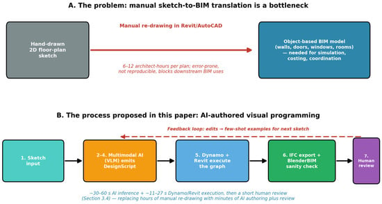
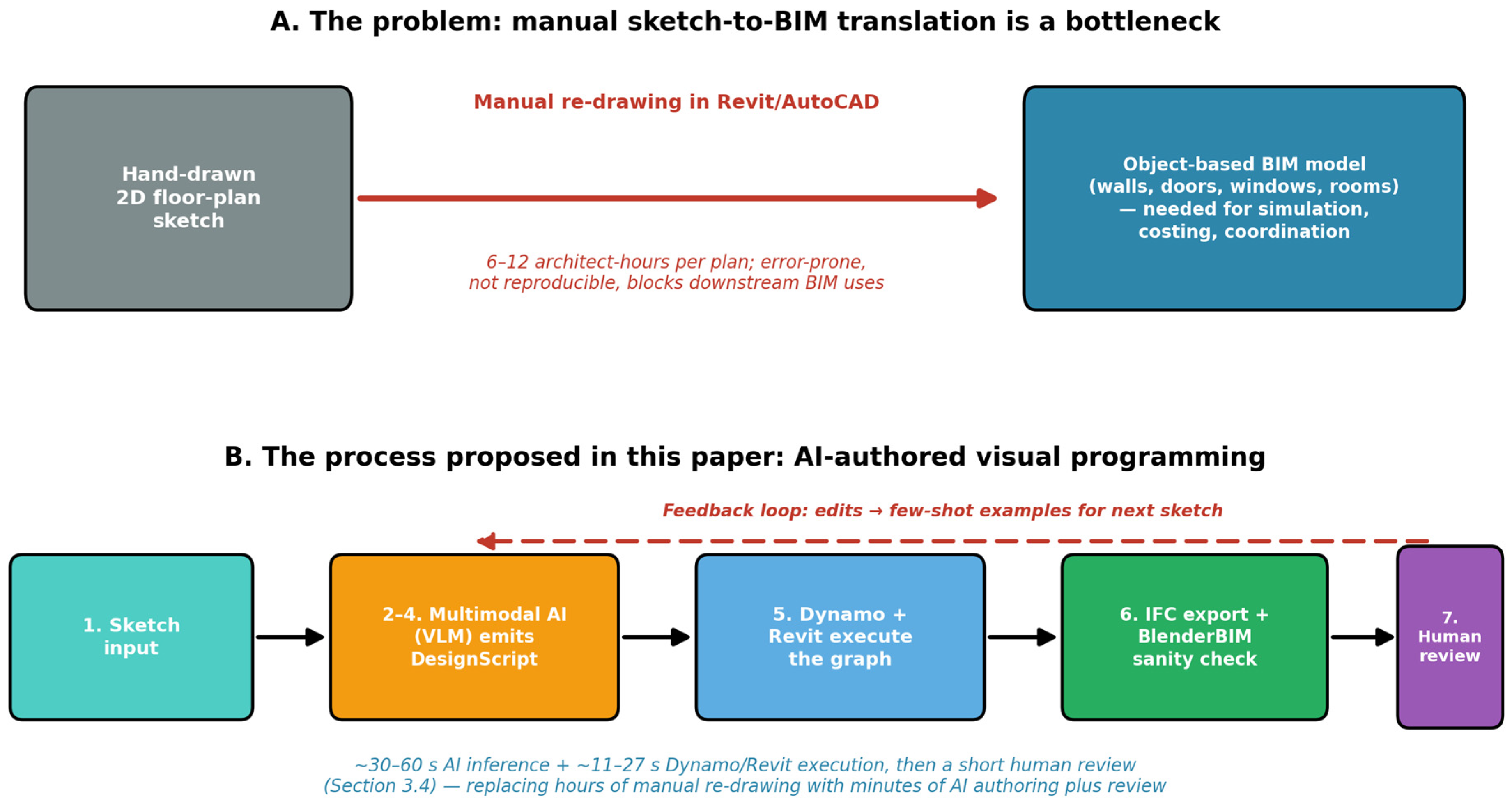
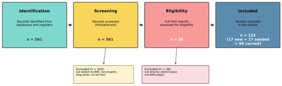
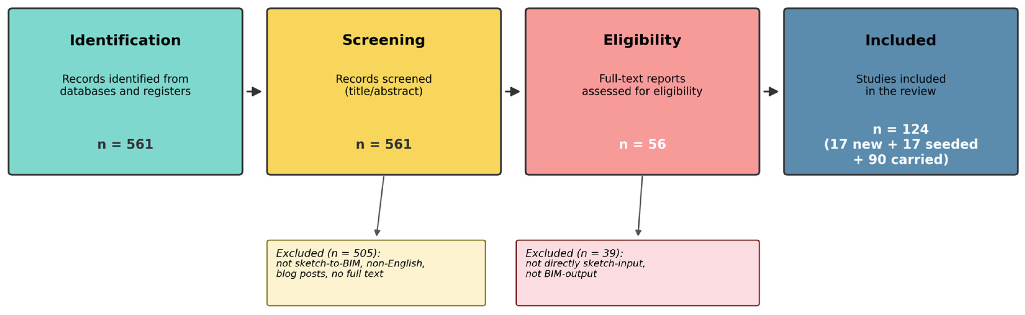
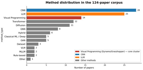
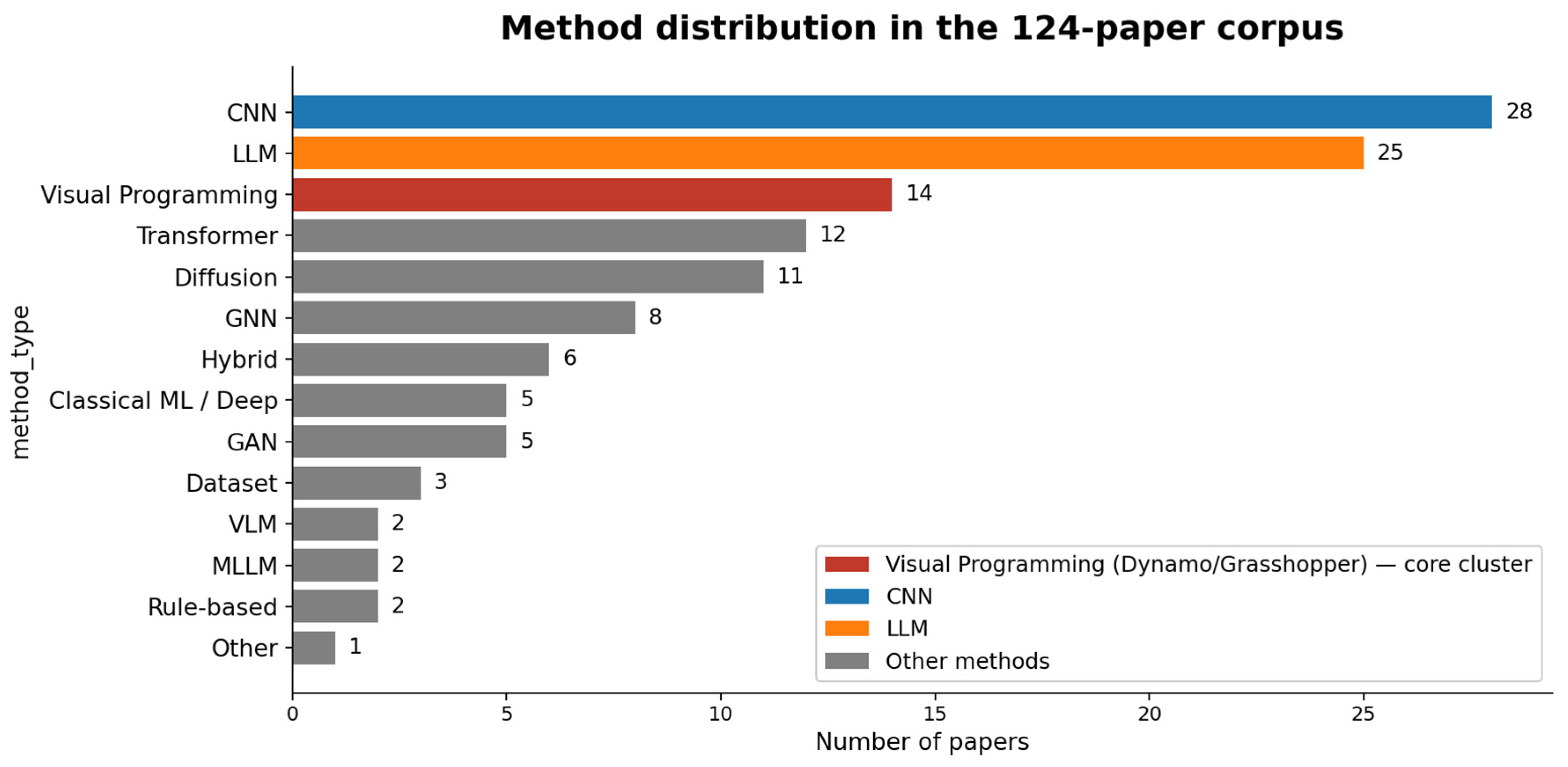
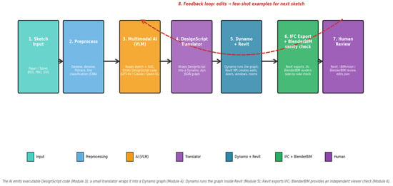
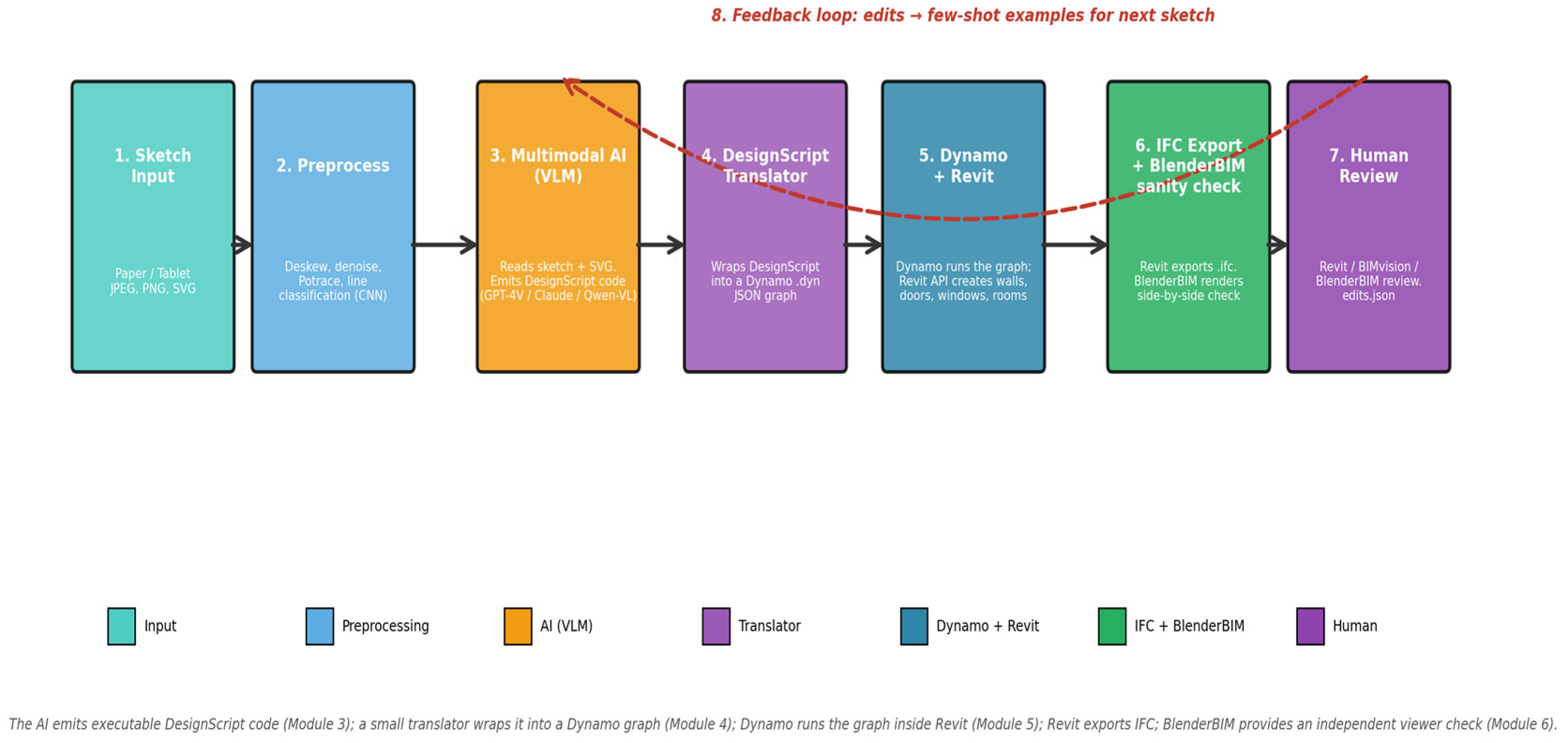
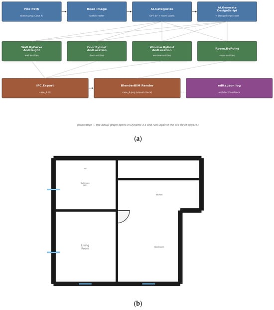
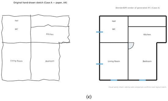
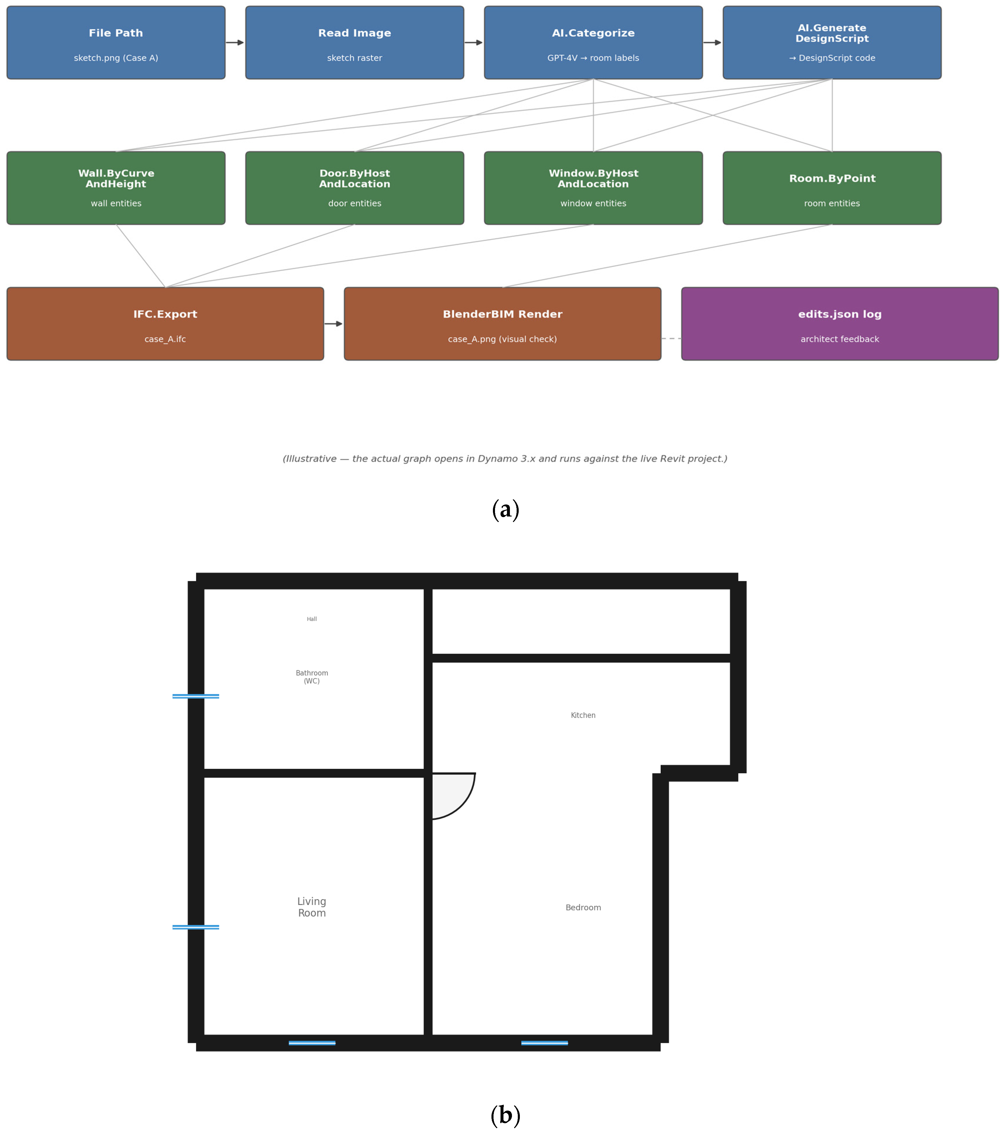
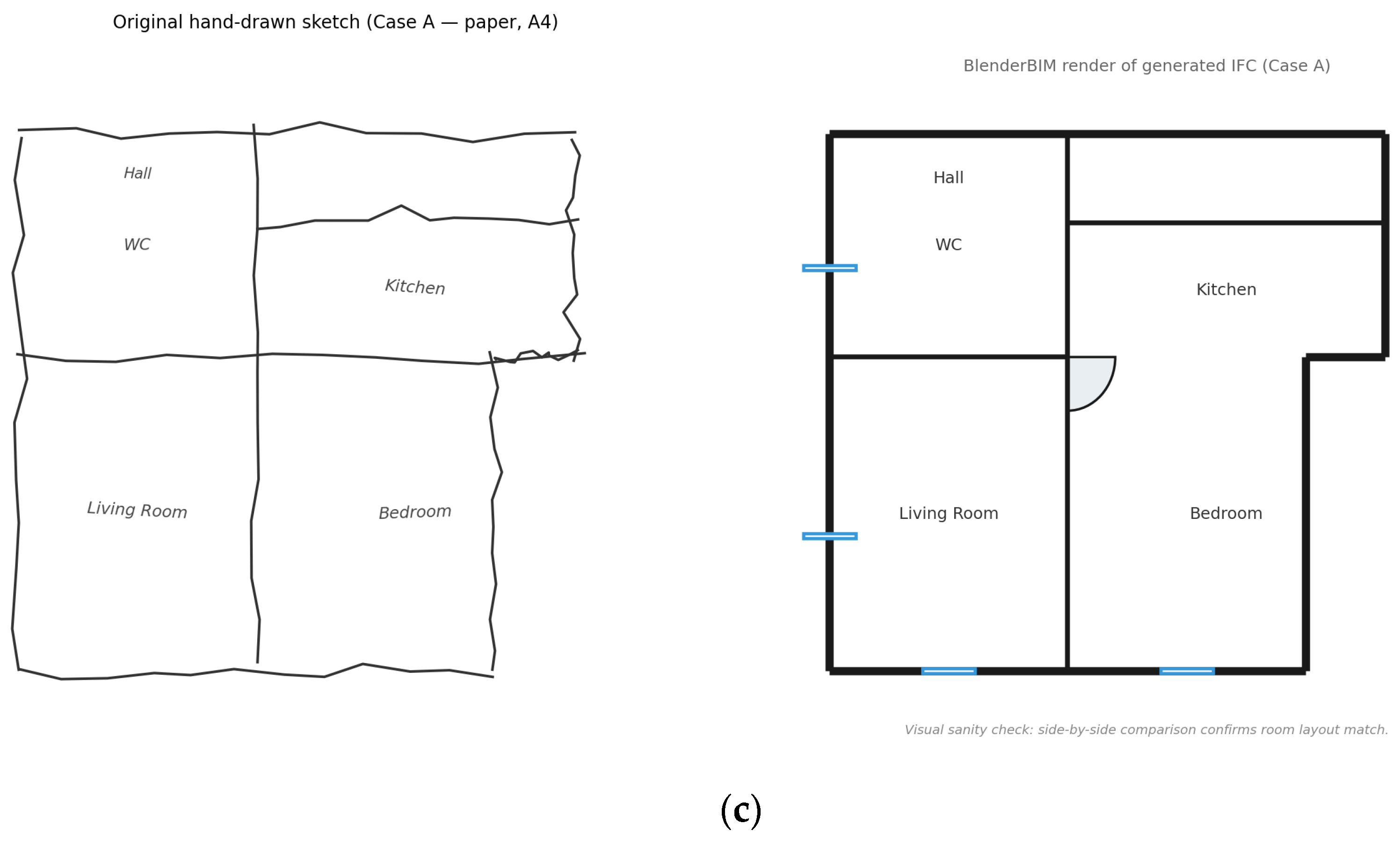
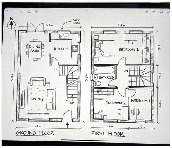
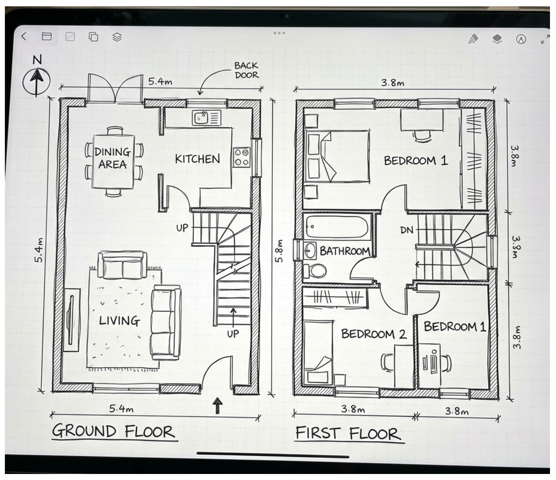
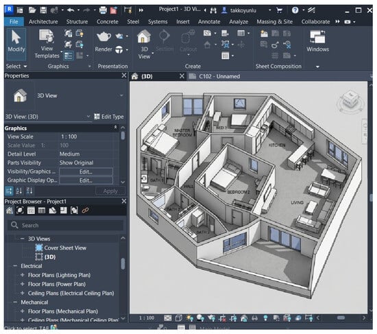
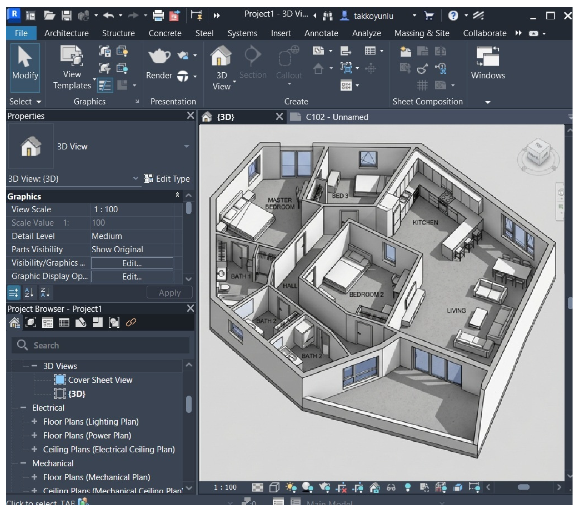
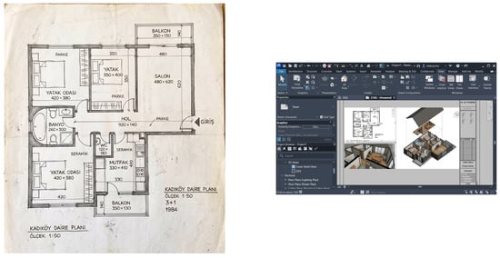
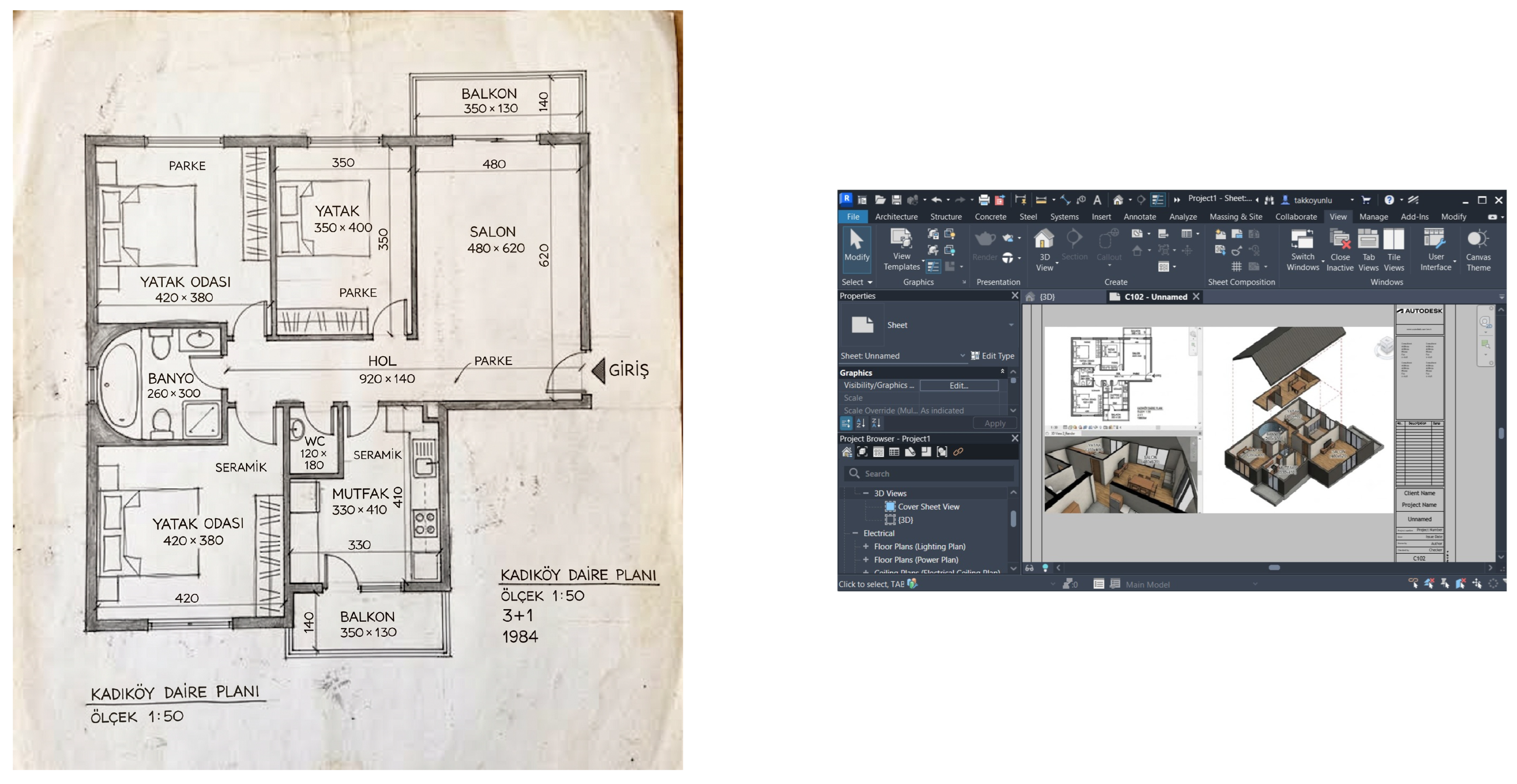

Disclaimer/Publisher’s Note: The statements, opinions and data contained in all publications are solely those of the individual author(s) and contributor(s) and not of MDPI and/or the editor(s). MDPI and/or the editor(s) disclaim responsibility for any injury to people or property resulting from any ideas, methods, instructions or products referred to in the content. |
© 2026 by the author. Licensee MDPI, Basel, Switzerland. This article is an open access article distributed under the terms and conditions of the Creative Commons Attribution (CC BY) license.