


Abstract
To address the deterioration of cold-region loess on the northeastern margin of the Qinghai–Tibet Plateau under freeze–thaw and wetting–drying cycles, as well as the reliance of enzyme-induced carbonate precipitation (EICP) on reagent-grade calcium sources, this study developed an EICP system using a calcium source derived from waste steel slag (SS-EICP). A combination of macro- and micro-scale experiments, including unconfined compressive strength (UCS), P-wave velocity, and scanning electron microscopy (SEM) analyses, was conducted to compare the strength characteristics, internal damage, and microstructure of SS-EICP-treated loess with those of CaCl2-EICP-treated loess. The results showed that SS-EICP achieved a UCS of 202.40 kPa at a reaction-solution dosage of 9%, equivalent to 95.9% of the peak UCS of CaCl2-EICP, with an optimum reaction-solution dosage 30.8% lower than that of CaCl2-EICP. After 10 freeze–thaw cycles, the UCS and P-wave velocity loss ratios were 52.22% and 24.54%, respectively; after 10 wetting–drying cycles, the mass loss ratio was 4.59%. Microstructural analysis indicated that cyclic damage mainly resulted from the disruption of CaCO3 cementation and the weakening of interparticle bonding. Overall, SS-EICP combines efficient stabilization at a low dosage with the resource-recovery benefits of waste steel slag, providing a promising pathway toward more sustainable stabilization of cold-region loess.
1. Introduction
Loess is widely distributed across Asia, Europe, and North America and is a distinctive engineering soil commonly encountered in highway and railway construction, slope engineering, and foundation engineering. Its loose and porous structure and natural cementation make loess highly sensitive to variations in moisture–thermal conditions, rendering it susceptible to collapsible deformation, reduced bearing capacity, differential settlement, and slope instability. The northeastern margin of the Qinghai–Tibet Plateau is characterized by a cold, high-altitude environment in which pronounced seasonal freeze–thaw processes and moisture migration expose loess to long-term cyclic moisture–thermal disturbances [1,2,3,4,5,6]. During freeze–thaw cycling, repeated freezing and thawing of pore water induce frost heave and thaw settlement, thereby promoting particle rearrangement, damage to cementation interfaces, and microcrack propagation. Repeated wetting–drying cycling can induce wetting-induced swelling and drying shrinkage, weaken cementation, and reorganize the pore structure, thereby reducing the structural integrity and mechanical stability of the soil [7,8]. Therefore, improving the resistance of loess to damage induced by freeze–thaw and wetting–drying cycles and developing green stabilization technologies that balance long-term service performance, resource conservation, and environmental sustainability are essential for the safe construction and long-term stability of foundations, slopes, and transportation infrastructure in cold regions.
Enzyme-induced carbonate precipitation (EICP) is a biomineralization-based technique for soil stabilization. In this process, urease catalyzes urea hydrolysis, and in the presence of Ca2+, CaCO3 precipitates within soil pores and at particle contacts, thereby enhancing soil strength and structural integrity through pore filling and interparticle cementation. Compared to microbially induced carbonate precipitation (MICP), EICP does not rely on the growth of living cells and is less constrained by microbial cell size and cultivation conditions, making it well-suited for the improvement in fine-grained soils [9,10,11]. Previous studies have shown that the stabilization performance of EICP depends not only on the amount of CaCO3 formed but also on reaction-solution composition, precipitation efficiency, and the spatial distribution and cementation morphology of CaCO3 at particle contacts [12,13,14,15]. Among these factors, the calcium source can alter the chemical environment of the reaction system and the nucleation and deposition behavior of CaCO3, making it an important factor governing EICP stabilization performance [16,17,18,19].
Conventional EICP systems typically rely on reagent-grade calcium salts, such as CaCl2, as sources of Ca2+, which can limit their economic viability and sustainability to some extent. Recovering usable Ca resources from Ca-rich industrial solid waste and converting them into alternative calcium sources provides a potential pathway for reducing the consumption of reagent-grade calcium salts while promoting the high-value utilization of industrial solid waste. Previous studies have explored alternative calcium-supply strategies and the utilization of Ca-containing wastes in EICP-related applications [20,21,22]. Steel slag is a typical Ca-rich industrial by-product of steelmaking that contains Ca-bearing components, including free CaO and calcium silicates, and therefore has considerable potential for Ca resource recovery [23]. Previous studies have used calcium sources extracted from steel slag through acid leaching for MICP biocementation [24], while others have directly coupled steel slag with EICP for tailings stabilization and explored the feasibility of synergistic steel slag treatment involving acid leaching and microbial mineralization [25,26]. These studies demonstrate the potential of steel slag-derived Ca resources for biomineralization. However, unlike the direct use of steel slag as a solid-phase material for stabilization, extracting usable Ca resources from steel slag in advance and converting them into an independent calcium source for EICP can extend its utilization beyond direct solid-phase application toward the high-value recovery and utilization of Ca resources. At present, studies on the use of steel slag-derived Ca2+ as an independent calcium source for the EICP stabilization of cold-region fine-grained loess remain limited, and systematic comparisons with conventional CaCl2-EICP systems in terms of stabilization efficiency and structural stability at the same Ca2+ concentration are particularly lacking.
In addition to initial stabilization performance, performance retention under cyclic environmental conditions is critical for evaluating the applicability of EICP-stabilized loess in cold regions. Previous studies have shown that freeze–thaw and wetting–drying cycles can cause strength degradation, disruption of CaCO3 cementation, and deterioration of the pore structure in MICP/EICP-stabilized soils [27,28]. Recent studies have further explored EICP-treated loess and loess-based materials from the perspectives of water-induced deformation, freeze–thaw resistance, and slope stabilization [29,30,31], indicating that research in this field is gradually expanding from initial stabilization performance to the evaluation of durability and performance stability under complex environmental conditions. Meanwhile, P-wave velocity is sensitive to changes in internal pores, cracks, and cementation continuity within the soil and is correlated, to some extent, with the strength of stabilized soil, making it a useful nondestructive indicator of cyclic damage [32,33]. However, few studies have simultaneously investigated freeze–thaw and wetting–drying behavior of cold-region loess stabilized by EICP using steel slag-derived calcium at the same Ca2+ concentration as the conventional CaCl2-EICP system while integrating mechanical performance, P-wave response, mass variation, crack evolution, and microstructural cementation characteristics into a multiscale evaluation. Therefore, whether steel slag-derived calcium can provide effective stabilization and maintain structural stability under cyclic environmental conditions while replacing reagent-grade CaCl2 is a key issue in evaluating the engineering applicability and resource-utilization value of this approach.
Accordingly, this study investigated cold-region loess from the northeastern margin of the Qinghai–Tibet Plateau. A Ca2+ solution was obtained by leaching steel slag with acetic acid, and a steel slag-derived calcium source EICP (SS-EICP) system was established at the same Ca2+ concentration as the CaCl2-EICP control. The study comprised three main components: (1) evaluating the feasibility of steel slag-derived Ca2+ as an EICP calcium source and the stabilization efficiency of SS-EICP through Ca leaching tests on steel slag and unconfined compression tests at different reaction-solution dosages, and determining appropriate treatment parameters; (2) conducting freeze–thaw and wetting–drying cycling tests on the optimized specimens and integrating unconfined compressive strength, P-wave velocity, mass variation, and crack characteristics to characterize the evolution of mechanical performance and internal damage in the stabilized loess under cyclic conditions; and (3) using X-ray diffraction (XRD) and scanning electron microscopy (SEM) to analyze mineralization products and interparticle cementation structures and to investigate the relationships among macroscopic mechanical responses, nondestructive acoustic characteristics, and microstructural evolution. This study aims to verify the feasibility of using steel slag-derived Ca2+ to replace reagent-grade CaCl2 as the calcium source for EICP stabilization of cold-region loess and to evaluate its adaptability under cyclic environmental conditions. It also aims to clarify the macro- and micro-scale responses associated with mineralization cementation and cyclic damage, thereby providing an experimental basis for reducing EICP reliance on reagent-grade calcium salts, promoting the high-value utilization of Ca resources from steel slag, and supporting the green and sustainable stabilization of cold-region loess.
2. Materials and Methods
2.1. Loess and Waste Steel Slag
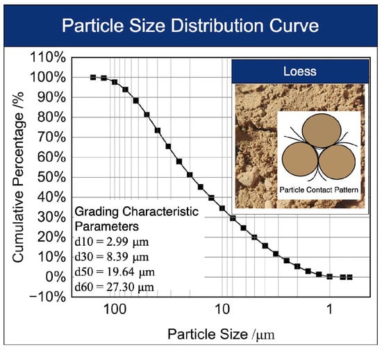
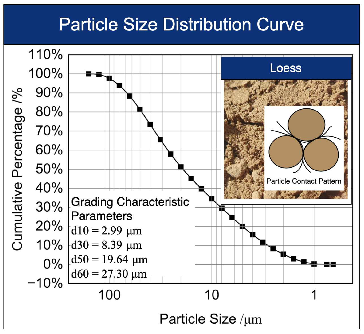
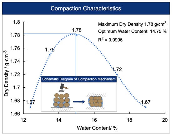
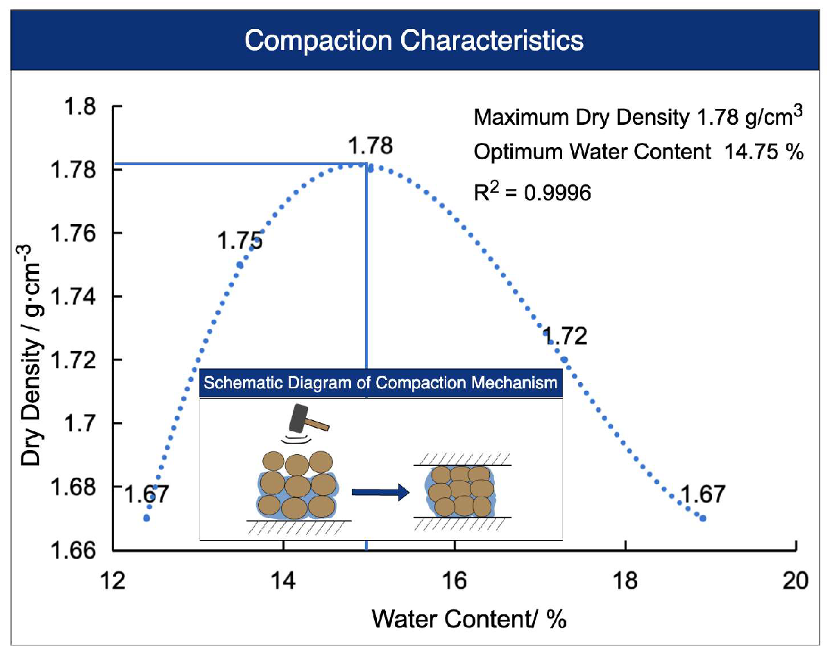
The loess used in this study was collected from the northeastern margin of the Qinghai–Tibet Plateau, China, at a depth of 3.0–4.0 m below the ground surface. After collection, the soil samples were air-dried indoors, gently disaggregated, and passed through a 2 mm sieve to remove plant residues and coarse particles. The basic physical properties of the loess, including the liquid limit, plastic limit, and compaction characteristics, were determined in accordance with the Standard for Geotechnical Testing Method (GB/T 50123-2019) [34]. The results are presented in Table 1, while the particle-size distribution and standard compaction curves are shown in Figure 1 and Figure 2, respectively. Based on its particle-size composition and plasticity indices, and in accordance with the Standard for Engineering Classification of Soil (GB/T 50145-2007) [35], the tested loess was classified as low-liquid-limit silt.
Table 1.
Basic physical properties of the loess.
Figure 1.
Particle-size distribution curve of the loess.
Figure 2.
Standard compaction curve of the loess.
The steel slag used in this study was obtained from a steel enterprise in Xining, China. The steel slag was crushed, sieved, and ball-milled, and subsequently passed through a 0.5 mm sieve to increase the contact area with the leaching solution and improve the uniformity of the leaching process. The major chemical composition of the steel slag was determined using X-ray fluorescence (XRF) spectroscopy (ZSX Primus II, Rigaku Corporation, Akishima, Tokyo, Japan), and the results are presented in Table 2. The CaO content of the steel slag was 39.60 wt.%, indicating its potential as a raw material for Ca resource recovery.
Table 2.
Major chemical components of the steel slag (wt.%).
2.2. EICP Reaction System
To evaluate the feasibility of using steel slag-derived Ca2+ to replace reagent-grade calcium salts as the calcium source for EICP, two systems—steel slag-derived calcium source EICP (SS-EICP) and CaCl2-EICP—were established at the same Ca2+ concentration. The two systems used identical amounts of urea and crude urease solution and identical specimen-treatment conditions, differing primarily in the source of Ca2+.
- (1)
- Preparation of the Soybean-Derived Crude Urease Solution
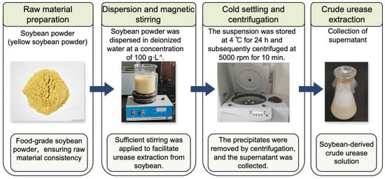
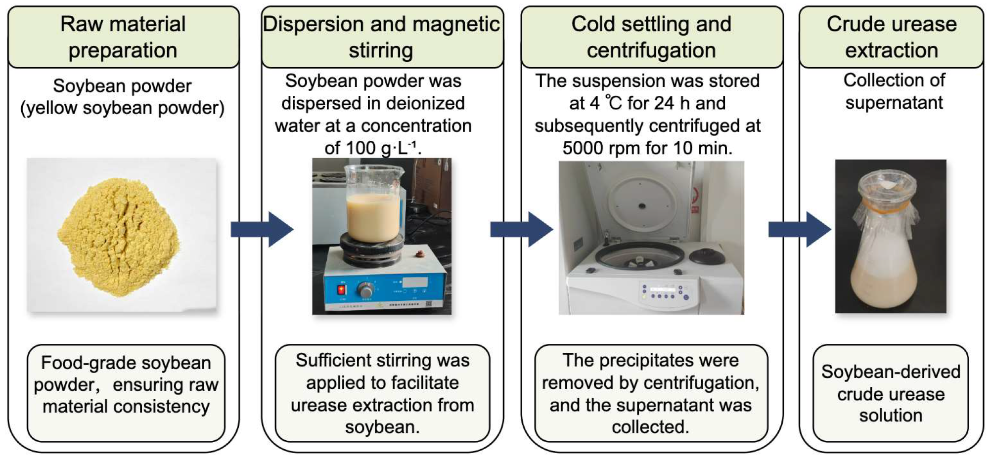
A crude urease solution was prepared from soybean powder using a simple extraction procedure. The preparation process is shown in Figure 3. Specifically, food-grade soybean powder was dispersed in deionized water at a concentration of 100 g·L−1, magnetically stirred for 30 min, and then allowed to stand at 4 °C for 24 h to allow proteins and solid particles to settle. The suspension was then centrifuged at 5000 rpm for 10 min using a centrifuge (Happy-TL21, Jinan Furuida Machinery Corporation, Jinan, China) to remove undissolved particles and precipitates, and the resulting supernatant was collected as the crude urease solution. During EICP treatment, the crude urease solution was mixed with the cementation solution at a volume ratio of 1:1 to induce urea hydrolysis and subsequent CaCO3 precipitation.
Figure 3.
Preparation process of the soybean-derived crude urease solution.
- (2)
- Chemical Reagents
All chemical reagents, including urea, calcium chloride, acetic acid, and sodium hydroxide, were of analytical grade. All solutions were prepared using deionized water and thoroughly stirred until complete dissolution before use.
- (3)
- Calcium Sources for the EICP Systems
The SS-EICP system used a steel slag-derived calcium solution as the calcium source, whereas the CaCl2-EICP system used an anhydrous CaCl2 solution as the control calcium source. The CaCl2 concentration was adjusted according to the measured Ca2+ concentration of the steel slag-derived calcium solution to ensure the same Ca2+ concentration in both systems.
- (4)
- Preparation of EICP Reaction Solutions
A 1.0 mol·L−1 urea solution was prepared and separately mixed with either the steel slag-derived calcium source or the CaCl2 control solution at a volume ratio of 1:1 to obtain the corresponding cementation solutions. Each cementation solution was then mixed with the crude urease solution at a volume ratio of 1:1 to obtain the corresponding SS-EICP or CaCl2-EICP reaction solution. Apart from the Ca2+ source, the amounts of urea and crude urease, component volume ratios, and subsequent specimen-treatment conditions were identical in the two systems.
2.3. Ca2+ Leaching Test of Steel Slag
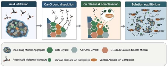
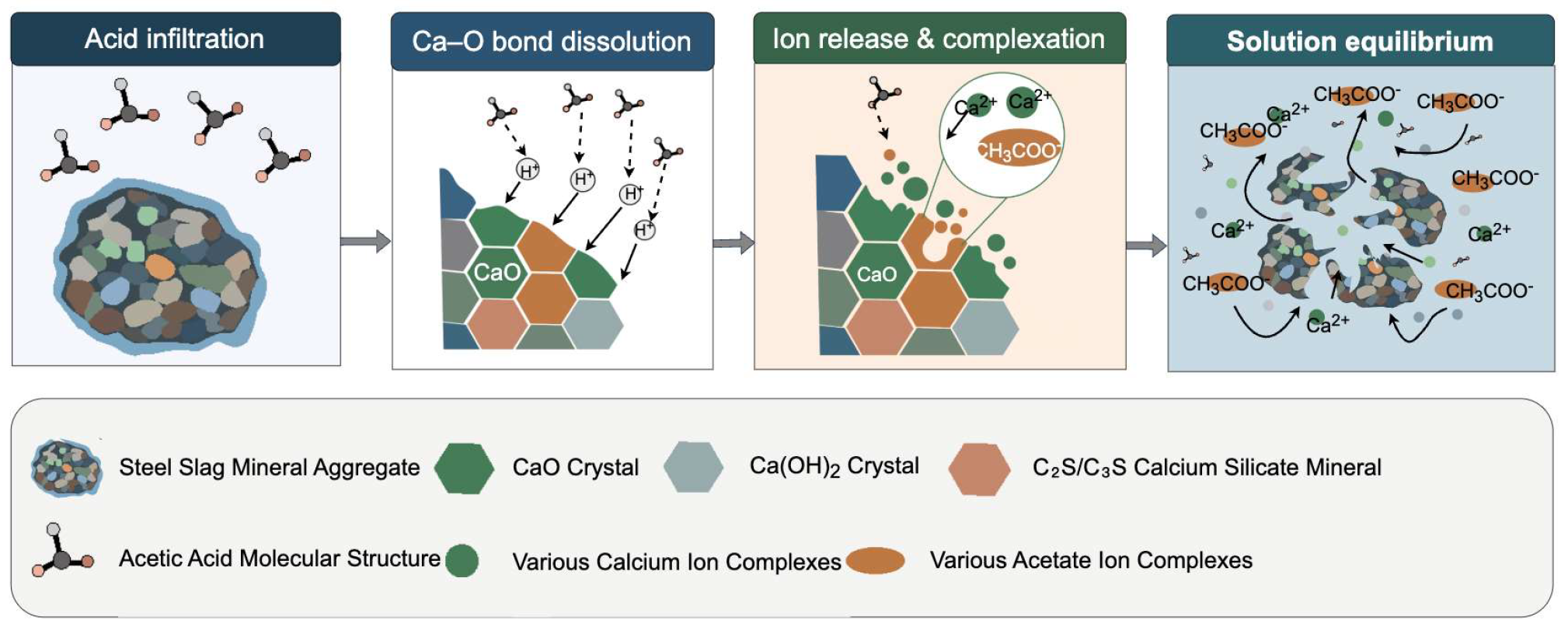
Single-factor experiments were conducted to investigate the effects of acetic acid concentration, water-bath temperature, and solid–liquid ratio on Ca2+ release from steel slag. The experimental design and factor levels for Ca²⁺ leaching from steel slag are summarized in Table 3. The calcium leaching and ion complexation mechanisms during acetic acid treatment are illustrated in Figure 4. The baseline conditions were an acetic acid concentration of 3.0 mol·L−1, a water-bath temperature of 50 °C, and a solid–liquid ratio of 48 g·L−1. The pretreated steel slag powder was added to the acetic acid solution at the prescribed solid loading, stirred at 600 rpm for 3 h at the designated temperature, and then sealed and allowed to stand for 24 h. During each single-factor test, all other variables were maintained at their baseline levels. Upon completion of leaching, solid–liquid separation was performed immediately. Insoluble residues were removed by filtration, and the Ca2+ concentration in the collected filtrate was determined by EDTA titration. Appropriate leaching conditions were selected by jointly considering the Ca2+ supply level, Ca extraction efficiency, acid input, and the requirements of the subsequent EICP process. The leachate obtained under the selected conditions had an initial pH of approximately 4.8. For each 100 mL of leachate, 1.1 mL of 4.0 mol·L−1 NaOH solution was first added dropwise under continuous stirring to adjust the pH to 5.0, followed by filtration to remove the precipitated impurities. Subsequently, 4.4 g of solid NaOH was added to the filtrate for coarse pH adjustment, after which 2.3 mL of 4.0 mol·L−1 NaOH solution was added dropwise for fine adjustment until a final pH of 7.0 was reached. The solution was then filtered again to remove the precipitated impurities, and the final filtrate was used as the steel slag-derived calcium source for the SS-EICP system.
Table 3.
Experimental design for Ca2+ leaching from steel slag.
Figure 4.
Schematic illustration of calcium leaching and ion complexation mechanisms in steel slag during acetic acid treatment.
2.4. Specimen Preparation and Curing
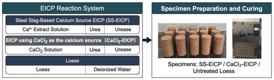
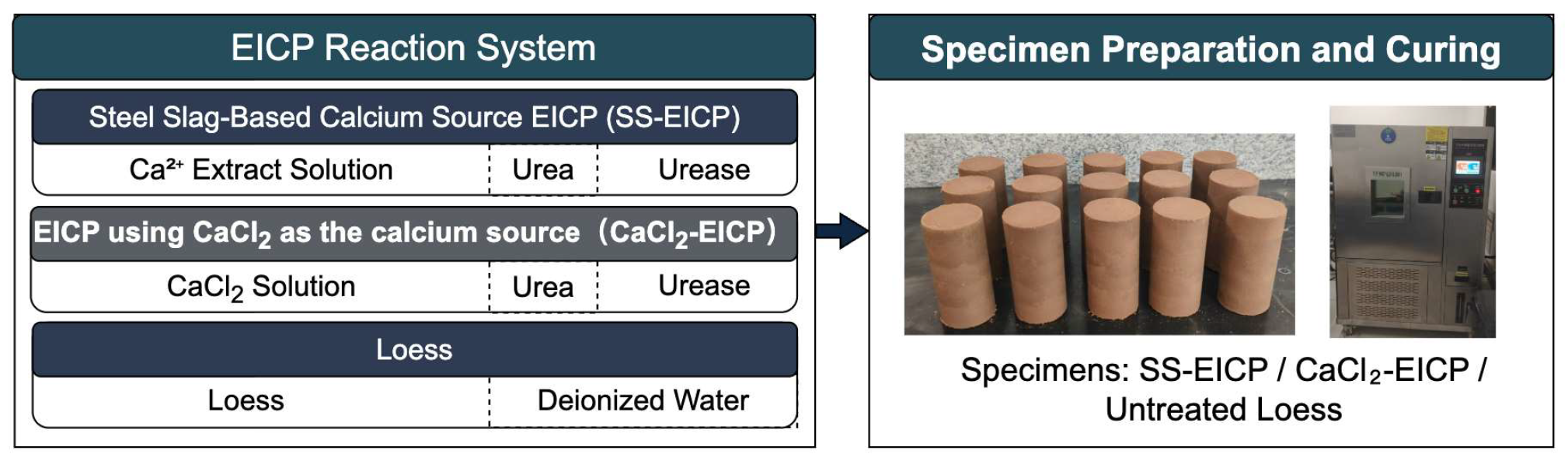
To compare the effects of different calcium-source systems and EICP reaction-solution dosages on loess stabilization performance, three types of specimens were prepared: untreated loess, SS-EICP-treated loess, and CaCl2-EICP-treated loess. The SS-EICP and CaCl2-EICP reaction solutions were prepared according to the procedure described in Section 2.2. The amounts of urea and crude urease and the mixing ratios of all components were identical in the two systems, with the primary difference being the Ca2+ source. The EICP reaction-solution dosage was defined as a percentage of the dry soil mass and was set at 7%, 9%, 11%, 13%, and 15%. The EICP reaction system and specimen preparation procedure are shown in Figure 5.
Figure 5.
Schematic diagram of the EICP reaction system and specimen preparation procedure.
The specimens were prepared using a mixing–static compaction method. First, the air-dried loess passing the 2 mm sieve was weighed to the designed mass, after which the prescribed amount of EICP reaction solution was added and thoroughly mixed with the soil. The water contained in the EICP reaction solution was included in the total water content of the specimen, and deionized water was added as needed to reach the optimum moisture content of 14.75%, ensuring an identical initial moisture content for all specimens at molding. The mixture was then placed in layers into a cylindrical mold 39.1 mm in diameter and 80 mm in height and compacted by static pressing to a target dry density of 95% of the maximum dry density.
Immediately after molding, the specimens were sealed to minimize moisture exchange during curing and maintained for 7 d in a controlled environment at 25 °C and 90% relative humidity. After curing, unconfined compressive strength (UCS) tests were conducted on the SS-EICP- and CaCl2-EICP-treated specimens at each reaction-solution dosage. Three replicate specimens (n = 3) were prepared and tested for each condition. The quantitative results are presented as mean ± standard deviation (SD). The resulting UCS values were then used to determine the appropriate reaction-solution dosage for each EICP system for subsequent environmental cycling tests.
2.5. Freeze–Thaw Cycling Test
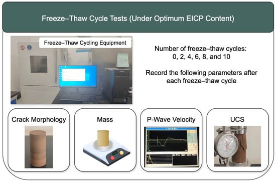
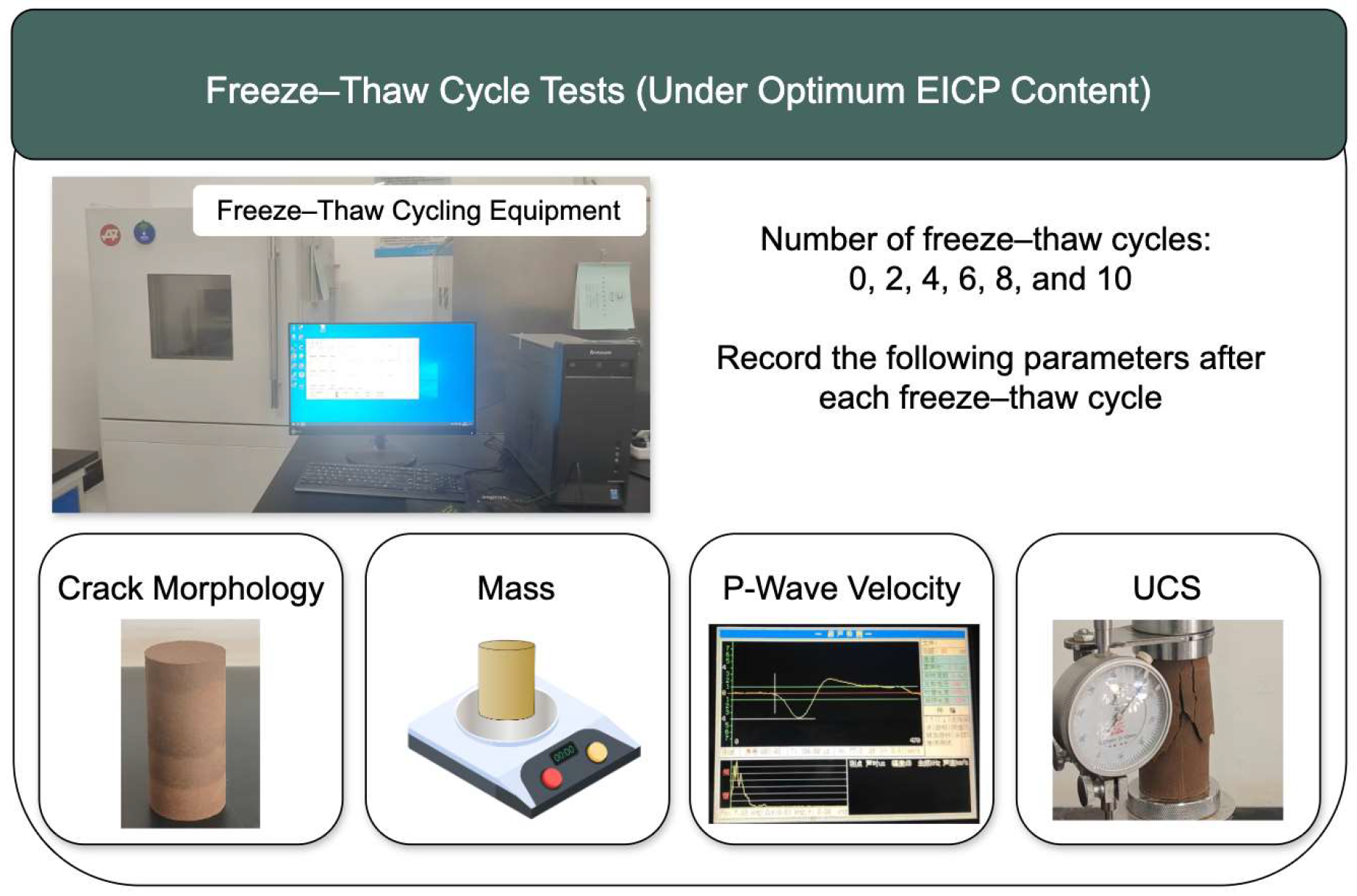
To evaluate the freeze–thaw resistance of loess stabilized by EICP using different calcium sources, SS-EICP and CaCl2-EICP specimens were prepared using the appropriate reaction-solution dosages determined in Section 2.4. After 7 d of curing, the specimens were subjected to laboratory freeze–thaw cycling tests. The freeze–thaw testing procedure and multi-parameter characterization are illustrated in Figure 6.
Figure 6.
Schematic illustration of the freeze–thaw testing procedure and multi-parameter characterization.
Freeze–thaw cycling was conducted in a programmable freeze–thaw cycling chamber (TMS9018, Tomos Technology Co., Ltd., Zhejiang, China). Each freeze–thaw cycle lasted 24 h and consisted of freezing at −20 °C for 12 h followed by thawing at 20 °C for 12 h. The numbers of freeze–thaw cycles were set to 0, 2, 4, 6, 8, and 10 to characterize the evolution of the stabilized loess with cumulative freeze–thaw cycling. The specimens remained sealed throughout freeze–thaw cycling to minimize moisture exchange with the surrounding environment, thereby allowing the effects of repeated freezing and thawing on the stabilized structure to be evaluated primarily.
After the prescribed number of freeze–thaw cycles, surface cracking, mass, P-wave velocity, and UCS were evaluated for the specimens. Surface crack morphology was used to characterize the initiation and propagation of macroscopic damage; mass variation was used to reflect material loss during cycling; P-wave velocity was used as a nondestructive indicator of internal crack development and changes in cementation continuity; and UCS was used to evaluate the retention of mechanical performance after cycling. Because the UCS test is destructive, independent specimens were used at each freeze–thaw cycle level. Three replicate specimens (n = 3) were prepared for each calcium-source system at each cycle level, with identical specimen-preparation, curing, and freeze–thaw conditions maintained to ensure comparability of the test results.
2.6. Wetting–Drying Cycling Test
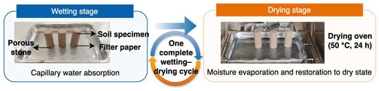
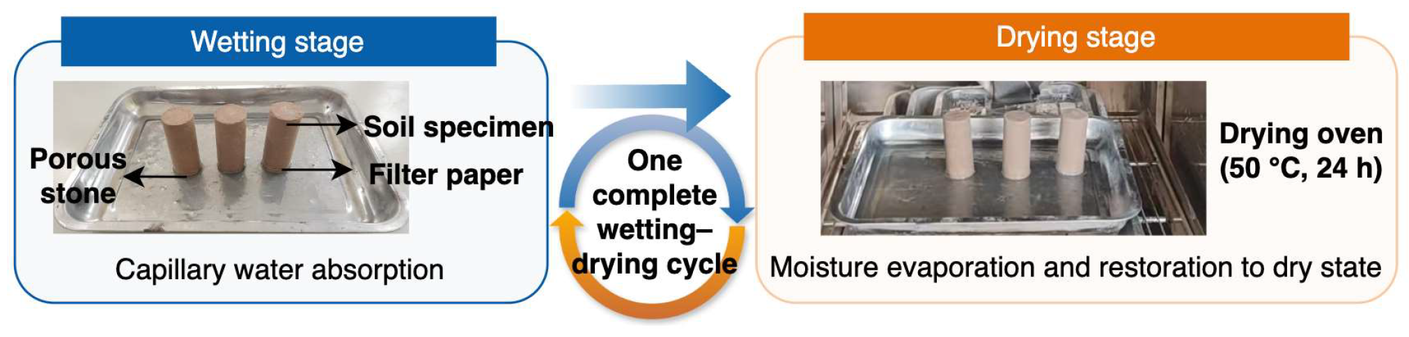
Cold-region loess on the northeastern margin of the Qinghai–Tibet Plateau is strongly affected by moisture processes such as precipitation, snowmelt, and evaporation, and repeated wetting and drying can induce soil volume changes and degradation of the cementation structure. To evaluate the structural stability of loess stabilized by EICP using different calcium sources under cyclic moisture conditions, laboratory wetting–drying cycling tests were conducted on specimens prepared at the appropriate reaction-solution dosages determined in Section 2.4. The wetting–drying cycling procedure is shown in Figure 7.
Figure 7.
Schematic diagram of the wetting–drying cycling procedure.
Wetting–drying cycling was performed using a capillary water absorption–constant-temperature drying procedure comprising wetting and drying stages. During the wetting stage, the SS-EICP and CaCl2-EICP specimens were weighed after 7 d of curing and then placed in a tray containing deionized water. A porous stone and filter paper were placed beneath each specimen to facilitate capillary water absorption and minimize particle loss. Based on the preliminary test results, the duration of capillary water absorption was set to 12 h. The wetted specimens were subsequently dried in a constant-temperature oven (DHG-9425A, Shanghai Changji Geological Instrument Co., Ltd., Shanghai, China) at 50 °C for 24 h to complete the drying stage. One complete capillary water absorption–constant-temperature drying process was defined as one wetting–drying cycle.
The numbers of wetting–drying cycles were set to 0, 2, 4, 6, 8, and 10. At each prescribed cycle level, UCS, P-wave velocity, mass variation, and crack morphology were evaluated to comprehensively characterize the mechanical performance, internal structure, and macroscopic damage evolution of the stabilized loess under wetting–drying cycling. Specimen-preparation, curing, and cycling conditions were kept identical at all cycle levels to ensure comparability between the two calcium-source systems.
2.7. UCS, Ultrasonic, Mass, and Crack Characterization
To comprehensively characterize the mechanical performance and structural damage of EICP-stabilized loess subjected to freeze–thaw and wetting–drying cycling, unconfined compressive strength (UCS), P-wave velocity, mass variation, and crack morphology were evaluated at each prescribed cycle level.
UCS was used to evaluate the macroscopic mechanical performance of the specimens after environmental cycling. Because the UCS test is destructive, independent replicate specimens were tested at each cycle level. Three replicate specimens (n = 3) were used for each test condition. The quantitative measurements of UCS, P-wave velocity, and specimen mass are presented as mean ± standard deviation (SD), and the error bars in the corresponding figures represent the SD.
P-wave velocity was measured using a non-metallic ultrasonic testing analyzer (NM-4A, Beijing Koncrete Engineering Testing Technology Co., Ltd., Beijing, China) as a nondestructive indicator of changes in internal pores, cracks, and cementation continuity within the specimens. During testing, the transducers were positioned at the two ends of each cylindrical specimen, with the measurement positions and contact conditions kept consistent. Each specimen was measured three times consecutively, and the mean value was taken as the P-wave velocity for the corresponding state. Changes in P-wave velocity with increasing cycle number were used to evaluate the evolution of internal structural integrity in the stabilized specimens.
Specimen mass was measured at each prescribed cycle level, and the corresponding mass loss ratio was calculated relative to the initial mass to characterize the extent of particle detachment and material loss during environmental cycling. Crack morphology was documented through periodic surface observations and image recording to characterize macroscopic damage features, including crack initiation, propagation, and localized spalling.
All measurements were conducted at the same cycle levels under consistent testing conditions. The combined analysis of UCS, P-wave velocity, mass variation, and crack morphology enabled a multiscale evaluation of mechanical degradation and structural damage in loess stabilized by EICP using different calcium sources under environmental cycling.
2.8. XRD and SEM Characterization
To investigate the involvement of steel slag-derived Ca2+ in EICP mineralization and the evolution of the cementation structure under environmental cycling, representative SS-EICP-treated loess specimens were characterized using an X-ray diffractometer (D/Max-2500PC, Rigaku Corporation, Tokyo, Japan) and a scanning electron microscope (JSM-6610LV, JEOL Ltd., Tokyo, Japan).
XRD was used to identify the major mineral phases and mineralization products in the specimens, with particular attention to CaCO3-related diffraction features and changes in crystalline phase composition before and after environmental cycling, thereby confirming the participation of steel slag-derived Ca2+ in EICP mineralization and the formation of CaCO3 precipitates.
SEM was used to examine the microstructural morphology of soil particle surfaces and particle-contact regions, with particular emphasis on the distribution of CaCO3 precipitates, pore filling, and interparticle cementation. By comparing changes in the integrity of cementation products, the development of pores and microcracks, and the state of particle connections before and after cycling, the microstructural damage characteristics of EICP cementation under environmental cycling were evaluated and related to the corresponding UCS, P-wave velocity, and macroscopic crack-evolution results.
2.9. Statistical Analysis and Model Fitting
The effects of calcium-source system (SS-EICP and CaCl2-EICP), cycle number, and their interaction on UCS, P-wave velocity, and specimen mass were evaluated using two-way analysis of variance (ANOVA). Freeze–thaw and wetting–drying data were analyzed separately, with statistical significance set at p < 0.05.
For model fitting, the relationship between the P-wave velocity loss ratio and the strength loss ratio was quantified using a power-law model, expressed as follows:
where Rv is the P-wave velocity loss ratio (%), Rs is the strength loss ratio (%), and a and b are the model-fitting parameters.
The model parameters were estimated using nonlinear least-squares regression, and the coefficient of determination (R2) was used to evaluate the goodness of fit. Statistical analyses, data processing, and curve fitting were performed using Origin 2021 and Python 3.10. By comparing the fitted relationships for different calcium-source systems and cyclic environmental conditions, the response of P-wave velocity to the evolution of mechanical damage in EICP-stabilized loess was analyzed, and the applicability of P-wave testing as a nondestructive indicator of cyclic damage was evaluated.
3. Results
3.1. Optimization of Ca2+ Leaching from Waste Steel Slag
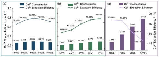
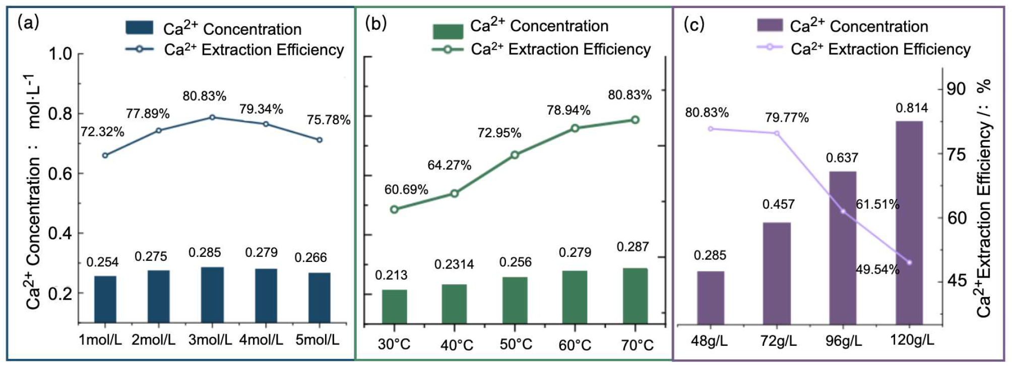
As shown in Figure 8, acetic acid concentration, leaching temperature, and solid–liquid ratio (steel slag/acetic acid solution) markedly affected Ca2+ release from steel slag. With increasing acetic acid concentration, both the Ca2+ concentration and Ca leaching efficiency initially increased and then decreased, reaching relatively high levels at 3.0 mol·L−1. This result indicated that further increases in acetic acid concentration did not result in a sustained enhancement of Ca release.
Figure 8.
Effects of operating conditions on Ca2+ leaching from steel slag: (a) acetic acid concentration; (b) leaching temperature; and (c) solid–liquid ratio.
As the leaching temperature increased, both the Ca2+ concentration and Ca leaching efficiency generally increased and tended to stabilize at higher temperatures, indicating that elevated temperatures promoted the dissolution of Ca-bearing components from steel slag, although the incremental benefit gradually diminished.
With increasing solid–liquid ratio, the Ca2+ concentration in the leachate increased from 0.285 to 0.814 mol·L−1, whereas the Ca leaching efficiency decreased from 80.83% to 49.54%, with the decline becoming pronounced above 72 g·L−1. This trend was mainly attributed to the lower acid-to-solid ratio at higher steel slag loadings. Under otherwise identical leaching conditions, the amount of acetic acid available per unit mass of steel slag decreased, so Ca release did not increase proportionally with the total amount of Ca introduced with the additional steel slag. Consequently, although the absolute amount of dissolved Ca2+ increased, a progressively smaller fraction of the total Ca in the steel slag was extracted.
Considering the Ca2+ concentration, Ca leaching efficiency, acetic acid utilization, and the Ca2+ concentration requirements of the subsequent EICP process, an acetic acid concentration of 3.0 mol·L−1, a leaching temperature of 70 °C, and a solid–liquid ratio of 96 g·L−1 were selected for preparing the SS-EICP calcium source.
Under these conditions, the Ca2+ concentration in the leachate reached 0.637 mol·L−1. After the stepwise pH adjustment and filtration described in Section 2.3, the measured Ca2+ concentration was 0.624 mol·L−1. The resulting solution was used as the steel slag-derived calcium source for the SS-EICP system, and 0.624 mol·L−1 was adopted as the reference Ca2+ concentration for the CaCl2-EICP control system. To normalize the reagent inputs, 100 mL of the pre-purification leachate was used as the calculation basis, corresponding to 0.0637 mol of recovered Ca2+. The corresponding acetic acid input was 0.300 mol, while the subsequent pH-adjustment procedure required a total NaOH input of 0.1236 mol. Accordingly, the normalized reagent inputs were 4.71 mol of acetic acid and 1.94 mol of NaOH per mol of recovered Ca2+.
3.2. Optimum Reaction-Solution Dosages for EICP Systems with Different Calcium Sources
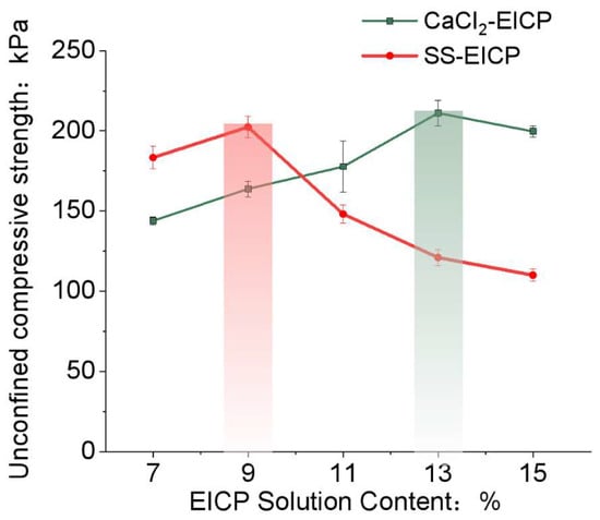
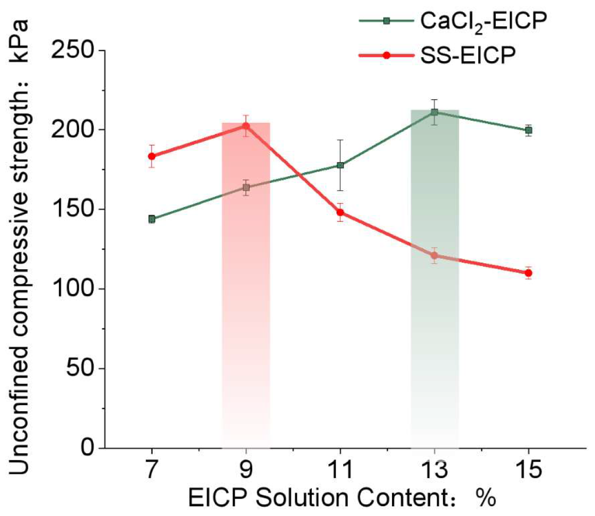
As shown in Figure 9, the UCS of both SS-EICP- and CaCl2-EICP-treated loess exhibited a pronounced dependence on reaction-solution dosage, although the dosages corresponding to the peak UCS differed markedly between the two calcium-source systems. For CaCl2-EICP-treated loess, UCS generally increased with increasing reaction-solution dosage, reaching a peak of 211.10 kPa at 13%, before decreasing slightly at 15%. In contrast, SS-EICP-treated loess exhibited relatively high strength at lower dosages, reaching a peak UCS of 202.40 kPa at 9%, followed by a gradual decrease as the dosage increased further.
Figure 9.
Effect of EICP reaction-solution dosage on the unconfined compressive strength (UCS) of loess treated with EICP systems using different calcium sources.
Within the lower reaction-solution dosage range of 7–9%, SS-EICP-treated loess exhibited higher UCS than CaCl2-EICP-treated loess. At reaction-solution dosages above 9%, the strength trends of the two systems diverged, with CaCl2-EICP-treated loess exhibiting progressively higher UCS than SS-EICP-treated loess. These results indicate that the mechanical response to reaction-solution dosage varies with the calcium-source system and that increasing the reaction-solution dosage does not necessarily result in higher stabilization strength.
Notably, SS-EICP-treated loess achieved a peak UCS of 202.40 kPa at a reaction-solution dosage of 9%, equivalent to 95.9% of the peak UCS achieved by CaCl2-EICP-treated loess. The reaction-solution dosage required to achieve the peak UCS decreased from 13% for CaCl2-EICP to 9% for SS-EICP, representing a 30.8% reduction. These findings indicate that the steel slag-derived calcium source can achieve a stabilization strength approaching the peak value of the reagent-grade CaCl2-EICP system at a substantially lower reaction-solution dosage, demonstrating an advantage in low-dosage stabilization. Based on the peak UCS results, specimens treated with 9% SS-EICP and 13% CaCl2-EICP were selected for subsequent comparative environmental cycling tests.
3.3. Evolution of Mechanical Performance Under Cyclic Environmental Conditions
3.3.1. UCS and Strength Loss Ratio Under Freeze–Thaw Cycling
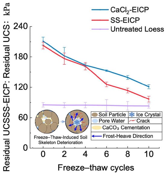
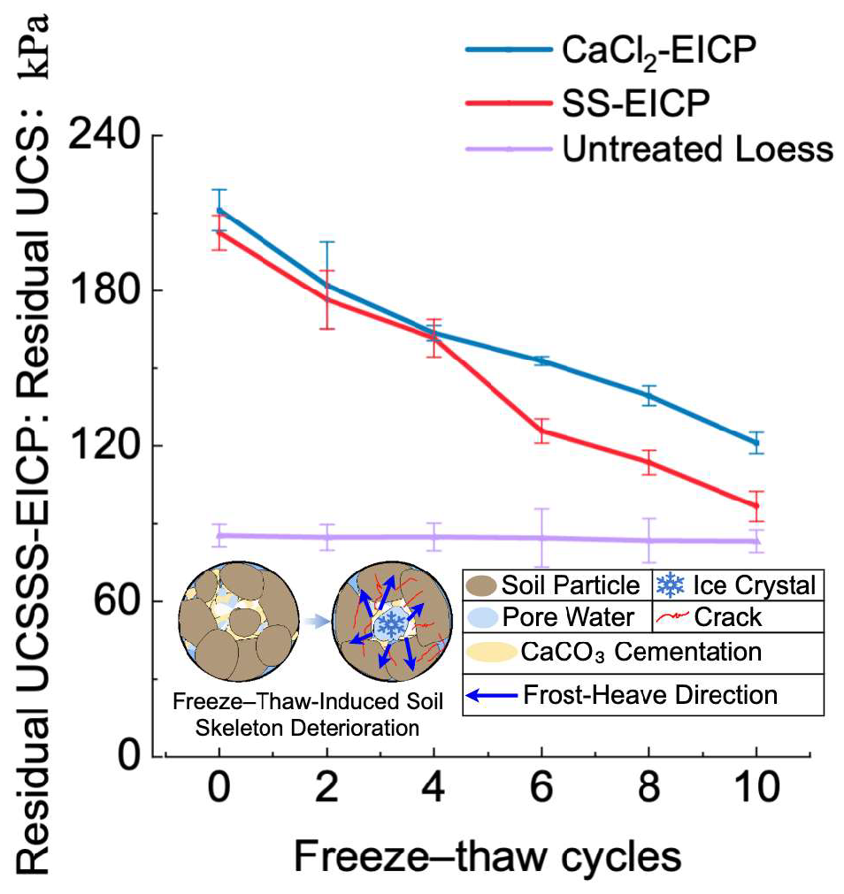
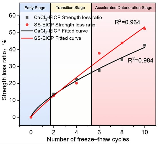
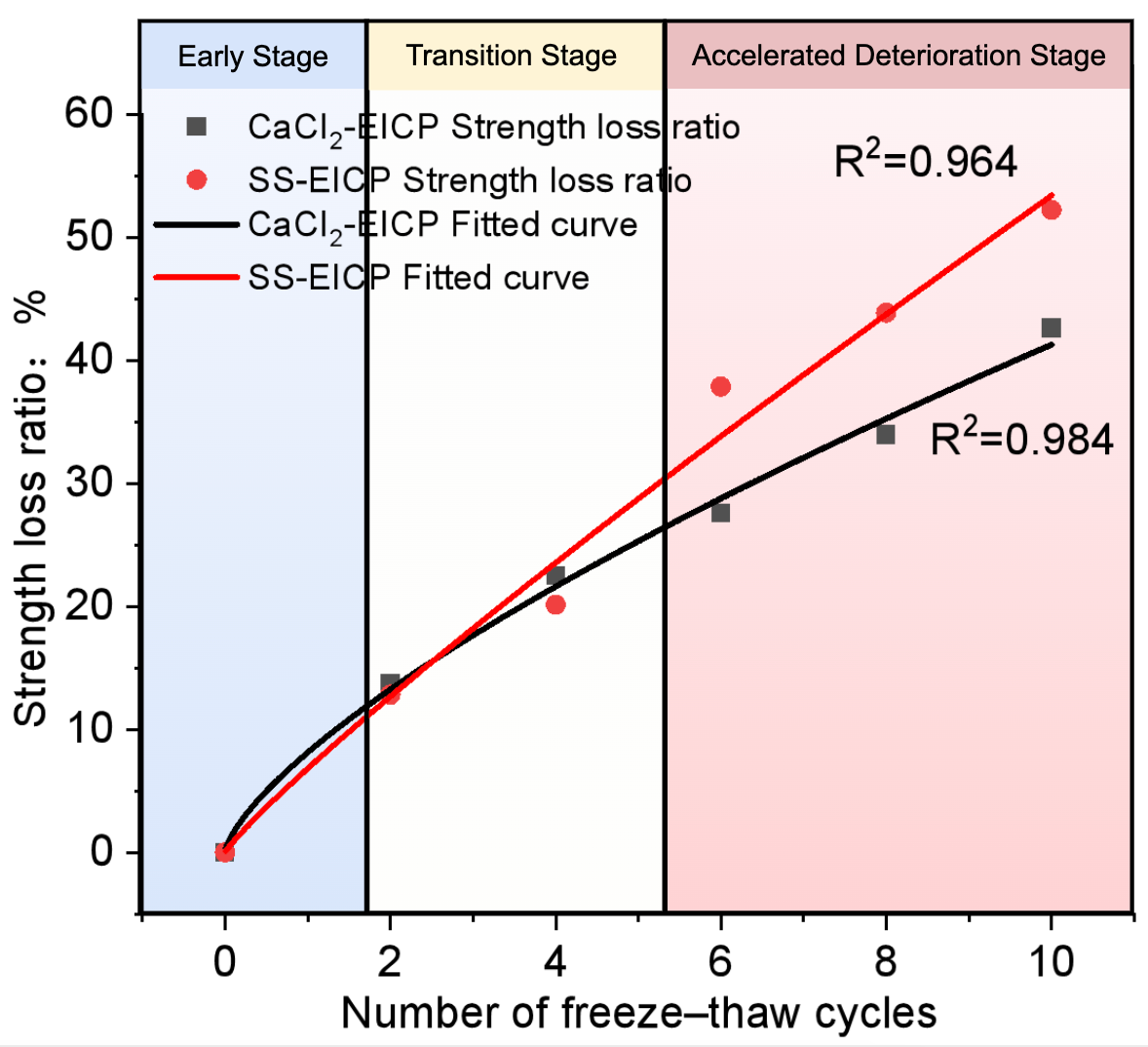
As shown in Figure 10 and Figure 11, the UCS of both SS-EICP- and CaCl2-EICP-treated loess decreased continuously with increasing freeze–thaw cycle number, whereas the strength of untreated loess changed only slightly. This contrast indicated that freeze–thaw cycling exerted a more pronounced cumulative effect on the mechanical performance of EICP-treated loess.
Figure 10.
Evolution of the unconfined compressive strength of EICP-treated and untreated loess under freeze–thaw cycling.
Figure 11.
Evolution of the strength loss ratio of EICP-treated loess under freeze–thaw cycling.
After 10 freeze–thaw cycles, the UCS of CaCl2-EICP-treated loess decreased from 211.10 to 121.13 kPa, corresponding to a strength loss ratio of 42.62%, whereas the UCS of SS-EICP-treated loess decreased from 202.40 to 96.70 kPa, corresponding to a strength loss ratio of 52.22%. Both systems exhibited relatively gradual strength degradation during the early freeze–thaw cycles, followed by progressively greater strength loss with increasing cycle number, indicating cumulative freeze–thaw damage.
Across the freeze–thaw cycle stages, the strength loss ratio of SS-EICP-treated loess was generally higher than that of CaCl2-EICP-treated loess. After 10 freeze–thaw cycles, the strength loss ratio of SS-EICP-treated loess exceeded that of CaCl2-EICP-treated loess by 9.60 percentage points, while CaCl2-EICP-treated loess retained a higher residual UCS. These results indicated that, under the present experimental conditions, CaCl2-EICP-treated loess exhibited better strength retention under freeze–thaw cycling, whereas SS-EICP-treated loess showed greater mechanical sensitivity to freeze–thaw damage.
Overall, freeze–thaw cycling caused progressive strength degradation in loess treated with both EICP systems, with more pronounced damage accumulation in SS-EICP-treated loess. These mechanical responses provided a macroscopic basis for the subsequent analyses of P-wave response and microstructural evolution.
3.3.2. UCS and Strength Retention Ratio Under Wetting–Drying Cycling
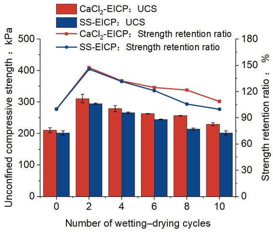
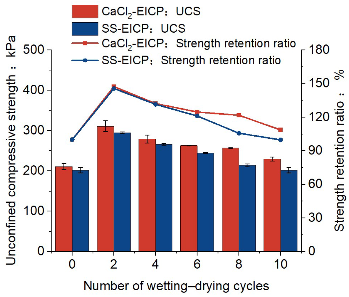
Figure 12 shows the evolution of UCS and the strength retention ratio of loess treated with EICP using different calcium sources under wetting–drying cycling. In contrast to the continuous strength degradation observed under freeze–thaw cycling, both EICP-treated loess systems exhibited a distinct stage-dependent response, with UCS initially increasing and subsequently decreasing.
Figure 12.
Evolution of the unconfined compressive strength and strength retention ratio of loess treated with EICP using different calcium sources under wetting–drying cycling.
Before wetting–drying cycling, the UCS values of CaCl2-EICP- and SS-EICP-treated loess were 211.10 and 202.40 kPa, respectively. After two wetting–drying cycles, the UCS increased markedly to 311.17 kPa for CaCl2-EICP-treated loess and 294.93 kPa for SS-EICP-treated loess. This initial increase may be primarily attributed to the reduction in specimen water content during drying and the resulting suction effect. Therefore, the observed increase is more appropriately interpreted as an apparent drying-induced strength enhancement rather than continued strengthening of the EICP-cemented structure itself.
With further wetting–drying cycling, the UCS of both systems gradually decreased from their respective peak values, indicating increasingly pronounced deterioration under repeated wetting and drying. After 10 cycles, the UCS decreased to 229.57 kPa for CaCl2-EICP-treated loess and 202.03 kPa for SS-EICP-treated loess, representing reductions of 26.2% and 31.5%, respectively, relative to the corresponding peak values after two cycles. SS-EICP-treated loess exhibited a greater post-peak reduction in UCS, indicating relatively higher mechanical sensitivity to repeated wetting–drying action.
To quantitatively characterize strength retention at different stages of wetting–drying cycling, the strength retention ratio, Rn, was defined as follows:
where Rn is the strength retention ratio after the n th wetting–drying cycle, UCS0 is the UCS before wetting–drying cycling, and UCSn is the UCS after the n th wetting–drying cycle.
3.4. P-Wave Response Under Cyclic Environmental Conditions
3.4.1. P-Wave Velocity and Velocity Loss Ratio Under Freeze–Thaw Cycling
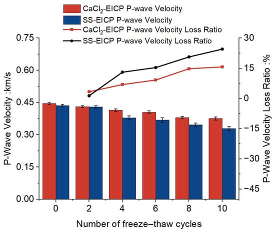
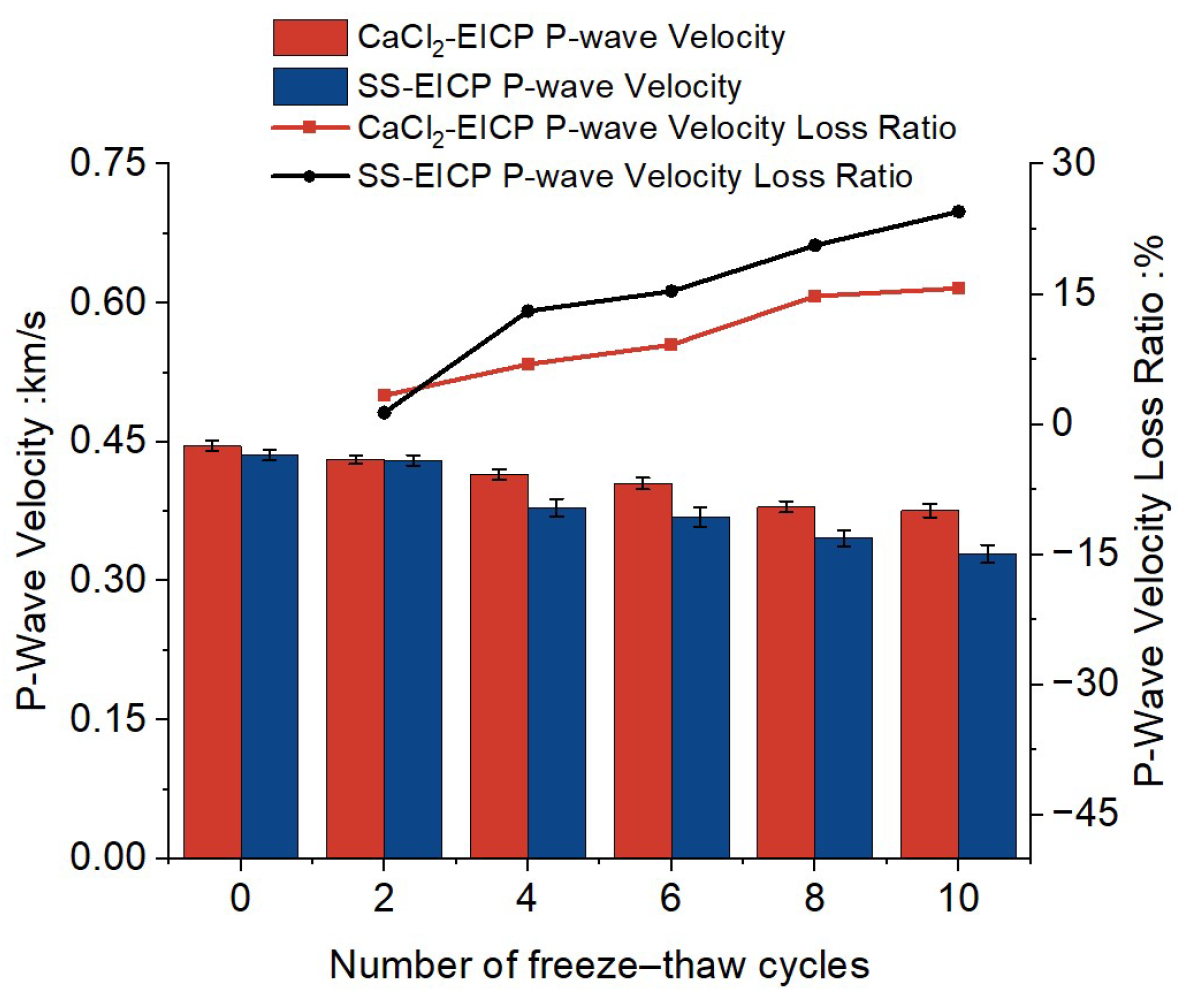
As shown in Figure 13, the P-wave velocities of both CaCl2-EICP- and SS-EICP-treated loess decreased continuously with increasing freeze–thaw cycle number, indicating a progressive change in wave-propagation characteristics within the specimens. Before freeze–thaw cycling, the P-wave velocities of CaCl2-EICP- and SS-EICP-treated loess were 0.446 and 0.436 km·s−1, respectively, indicating comparable initial wave-propagation characteristics.
Figure 13.
Evolution of P-wave velocity and P-wave velocity loss ratio of loess treated with EICP using different calcium sources under freeze–thaw cycling.
To quantitatively characterize the response of P-wave velocity to freeze–thaw cycling, the P-wave velocity loss ratio, Dv, was defined as follows:
where V0 is the initial P-wave velocity before freeze–thaw cycling, Vn is the P-wave velocity after the n th freeze–thaw cycle, and Dv is the P-wave velocity loss ratio.
The P-wave velocity loss ratios of both systems increased progressively with increasing freeze–thaw cycle number. After 10 freeze–thaw cycles, the P-wave velocities decreased to 0.376 km·s−1 for CaCl2-EICP-treated loess and 0.329 km·s−1 for SS-EICP-treated loess, corresponding to velocity loss ratios of 15.70% and 24.54%, respectively. SS-EICP-treated loess exhibited a greater reduction in P-wave velocity, indicating that its internal structural integrity was more sensitive to freeze–thaw cycling.
Overall, P-wave velocity decreased progressively in loess treated with both EICP systems during freeze–thaw cycling, with a more pronounced reduction observed in SS-EICP-treated loess. This trend was generally consistent with the previously observed UCS degradation, providing support for the use of P-wave velocity as a nondestructive indicator of internal damage in EICP-treated loess under freeze–thaw cycling.
3.4.2. P-Wave Velocity and Velocity Retention Ratio Under Wetting–Drying Cycling
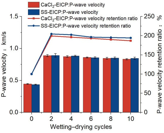
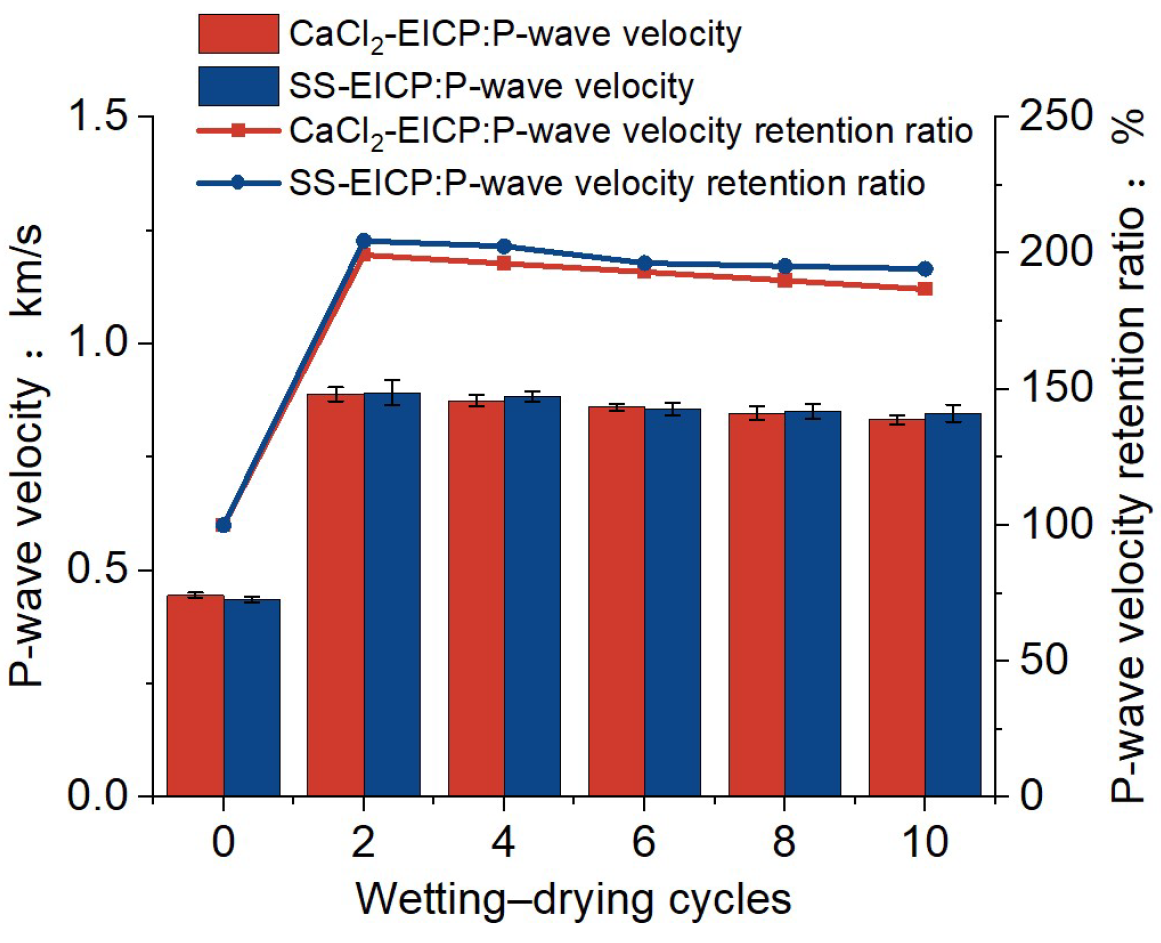
As shown in Figure 14, the P-wave velocities of loess treated with both EICP systems exhibited a distinct stage-dependent response under wetting–drying cycling. Before wetting–drying cycling, the P-wave velocities of SS-EICP- and CaCl2-EICP-treated loess were 0.436 and 0.446 km·s−1, respectively. After two wetting–drying cycles, the P-wave velocities increased markedly to 0.892 and 0.889 km·s−1, respectively, indicating a pronounced initial increase in wave velocity.
Figure 14.
Evolution of P-wave velocity and velocity retention ratio of loess treated with EICP using different calcium sources under wetting–drying cycling.
Because P-wave propagation is influenced not only by pore structure and cementation but also by specimen moisture conditions and transducer contact conditions, the initial increase in P-wave velocity should not be directly interpreted as strengthening of the stabilized structure itself. In conjunction with the corresponding UCS response, this increase more likely reflected drying-induced changes in specimen moisture conditions and the resulting wave-propagation characteristics and can therefore be regarded as an apparent acoustic enhancement.
With further wetting–drying cycling, the P-wave velocities of both systems gradually decreased from the high values observed after two cycles. After 10 cycles, the P-wave velocities were 0.847 km·s−1 for SS-EICP-treated loess and 0.833 km·s−1 for CaCl2-EICP-treated loess. Relative to the values after two cycles, the P-wave velocities decreased by approximately 5.0% and 6.3%, respectively. Although P-wave velocity decreased during the later stages, its reduction was substantially smaller than the corresponding decrease in UCS from the peak values, indicating that P-wave velocity and macroscopic strength exhibited different sensitivities to wetting–drying-induced damage.
Overall, the P-wave response under wetting–drying cycling exhibited a stage-dependent pattern characterized by a rapid initial increase followed by a gradual decrease, broadly corresponding to the stage-dependent evolution of UCS. The relatively limited decrease in P-wave velocity during the later stages suggested that P-wave velocity primarily reflected changes in the overall wave-propagation paths and structural continuity of the specimens, whereas macroscopic strength may be more sensitive to localized cementation damage and the development of weak zones. The P-wave velocity retention ratio, Rv, was calculated as follows:
where Rv is the P-wave velocity retention ratio after the n th wetting–drying cycle, V0 is the P-wave velocity before wetting–drying cycling, and Vn is the P-wave velocity after the n th wetting–drying cycle.
3.5. Mass Variation and Crack Evolution
3.5.1. Mass Loss and Crack Evolution Under Freeze–Thaw Cycling
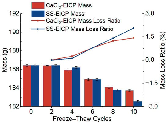
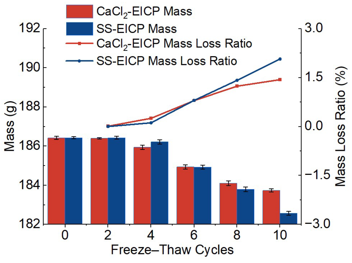
As shown in Figure 15, the mass of both CaCl2-EICP- and SS-EICP-treated loess specimens decreased progressively with increasing freeze–thaw cycle number. Before freeze–thaw cycling, the initial masses of the CaCl2-EICP- and SS-EICP-treated specimens were 186.42 and 186.43 g, respectively, indicating that their initial masses were essentially identical. To quantitatively characterize material loss during freeze–thaw cycling, the mass loss ratio, Dm, was defined as follows:
where m0 is the initial specimen mass before freeze–thaw cycling, mn is the specimen mass after the n th freeze–thaw cycle, and Dm is the corresponding mass loss ratio.
Figure 15.
Evolution of mass loss in EICP-treated loess under freeze–thaw cycling.
As freeze–thaw cycling progressed, the mass loss ratios of both systems increased progressively, with SS-EICP-treated loess exhibiting more pronounced mass loss. After 10 freeze–thaw cycles, the mass of CaCl2-EICP-treated loess decreased from 186.42 to 183.74 g, corresponding to a cumulative mass loss ratio of 1.44%. For SS-EICP-treated loess, the mass decreased from 186.43 to 182.57 g, corresponding to a cumulative mass loss ratio of 2.07%, which was 0.63 percentage points higher than that of CaCl2-EICP-treated loess.
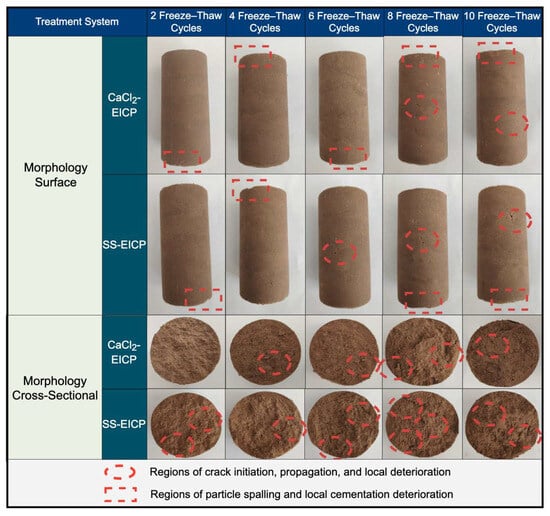
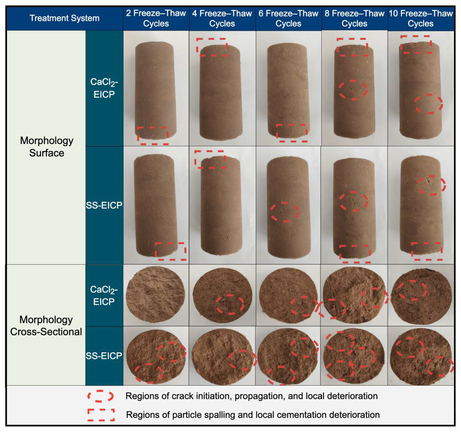
Figure 16 shows the evolution of the surface and cross-sectional morphologies of the specimens with increasing freeze–thaw cycle number. During the early stages of freeze–thaw cycling (2–4 cycles), specimens treated with both EICP systems remained largely intact, with only a few localized microcracks observed. With increasing cycle number, cracks gradually initiated and propagated, accompanied by deterioration of cemented regions and particle loosening. After 10 freeze–thaw cycles, CaCl2-EICP-treated loess retained relatively good structural integrity, whereas SS-EICP-treated loess exhibited more pronounced crack propagation, particle detachment, and localized loosening. The trends in mass loss and crack evolution were consistent with the previously observed UCS degradation and P-wave response.
Figure 16.
Evolution of surface and cross-sectional crack characteristics of EICP-treated loess under freeze–thaw cycling.
3.5.2. Mass Variation and Crack Evolution Under Wetting–Drying Cycling
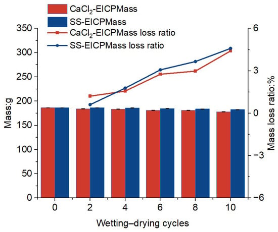
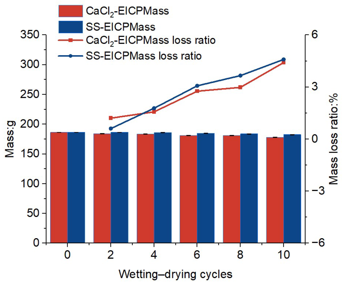
For wetting–drying cycling, the mass loss ratio was calculated relative to the initial specimen mass and was used as a quantitative index of specimen mass variation under the prescribed test condition. As shown in Figure 17, with increasing wetting–drying cycle number, the mass loss ratios of both systems increased progressively, with SS-EICP-treated loess exhibiting slightly greater mass loss. After 10 wetting–drying cycles, the specimen mass decreased to 178.20 g for CaCl2-EICP-treated loess and 177.88 g for SS-EICP-treated loess, corresponding to cumulative mass loss ratios of 4.41% and 4.59%, respectively.
Figure 17.
Evolution of mass loss in loess treated with EICP using different calcium sources under wetting–drying cycling.
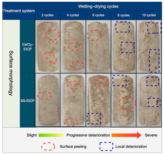
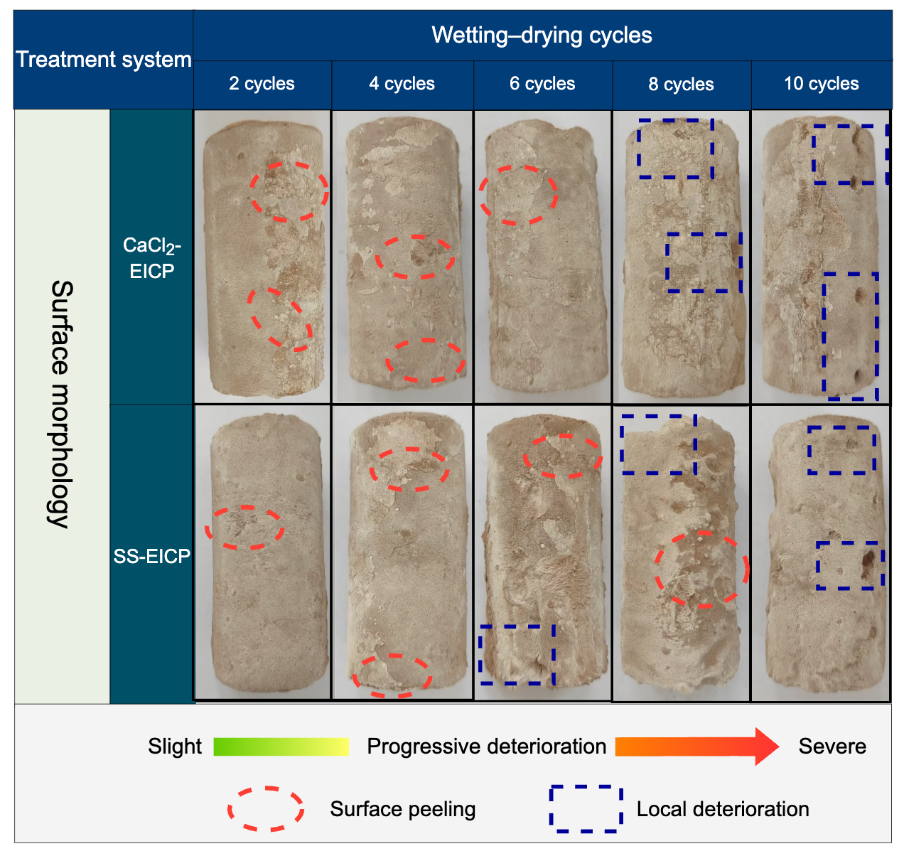
Figure 18 shows the evolution of specimen surface morphology with increasing wetting–drying cycle number. During the early stages of wetting–drying cycling (2–4 cycles), specimens treated with both EICP systems remained largely intact, with only a few localized cracks observed. This suggested that the initial moisture variations mainly induced soil shrinkage and adjustment of the cementation interfaces. With increasing cycle number, repeated wetting-induced swelling and drying shrinkage promoted crack initiation and propagation and were accompanied by localized deterioration of cemented regions.
Figure 18.
Surface morphology of EICP-treated loess specimens after different numbers of wetting–drying cycles.
3.6. Quantitative Relationship Between P-Wave Velocity Loss Ratio and Strength Loss Ratio
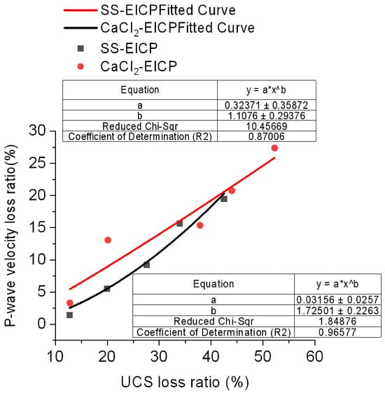
Following the methodology described in Section 2.9, the relationship between the P-wave velocity loss ratio and strength loss ratio was fitted separately for freeze–thaw and wetting–drying cycling. For freeze–thaw cycling, the pre-cycling state was used as the reference for damage evaluation. As shown in Figure 19, the P-wave velocity loss ratio increased nonlinearly with increasing UCS loss ratio for both calcium-source systems, indicating a close correspondence between acoustic response and strength degradation under freeze–thaw cycling. Within the tested range, SS-EICP generally exhibited a higher P-wave velocity loss ratio, indicating greater acoustic sensitivity to freeze–thaw cycling. This trend was broadly consistent with the previously observed UCS degradation, mass loss, and crack evolution.
Figure 19.
Fitted relationship between P-wave velocity loss ratio and strength loss ratio of EICP-treated loess under freeze–thaw cycling.
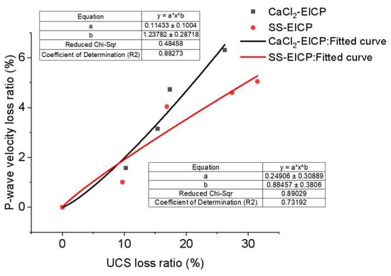
For wetting–drying cycling, because both UCS and P-wave velocity increased markedly during the first two cycles, the peak state after two cycles was used as the reference for subsequent damage evaluation. As shown in Figure 20, the post-peak P-wave velocity loss ratio also increased overall with increasing UCS loss ratio, although the relative positions of the fitted curves for the two systems differed from those under freeze–thaw cycling. During the later stages of wetting–drying cycling, the reduction in P-wave velocity was substantially smaller than the corresponding reduction in UCS. This difference suggests that P-wave velocity primarily reflects changes in the overall wave-propagation paths and structural continuity of the specimens, whereas macroscopic strength may be more sensitive to localized cementation damage.
Figure 20.
Fitted relationship between P-wave velocity loss ratio and strength loss ratio of EICP-treated loess under wetting–drying cycling.
Overall, the P-wave velocity loss ratio exhibited a clear nonlinear relationship with the UCS loss ratio, supporting its use as a nondestructive indicator of cyclic damage in EICP-treated loess. However, the fitted parameters varied between calcium-source systems and cyclic environmental conditions, indicating that the relationship between acoustic response and mechanical damage depends on both material characteristics and environmental conditions.
3.7. Analysis of Microstructural Evolution Mechanisms
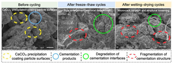
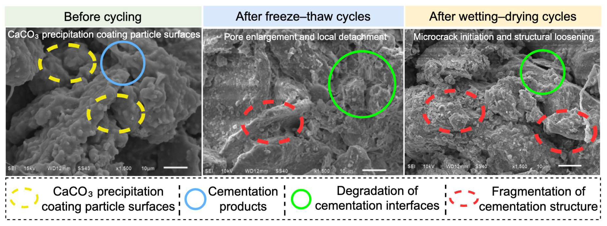
As shown in Figure 21, abundant mineralization products were observed on particle surfaces and at particle contacts in SS-EICP-treated loess before environmental cycling. The interpretation of these features was based on their SEM morphology and spatial distribution, together with the CaCO3 phase identified by XRD in Figure 22 and similar microstructural characteristics of EICP-treated soils reported in Ref. [13]. These products partially filled the pores and formed interparticle cementation, supporting the involvement of steel slag-derived Ca2+ in EICP mineralization and its contribution to enhanced particle bonding.
Figure 21.
SEM images of SS-EICP-treated loess before and after environmental cycling.
Figure 22.
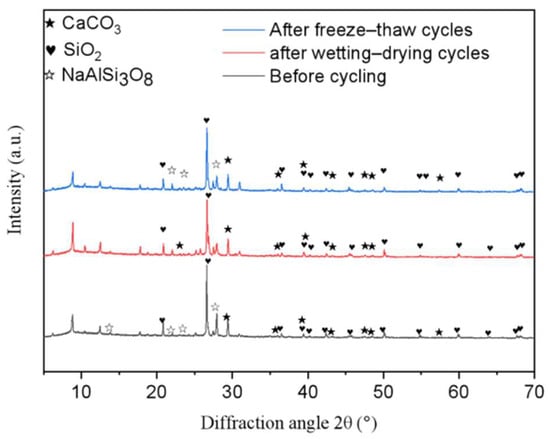
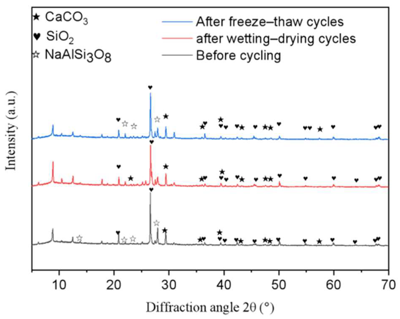
XRD patterns of SS-EICP-treated loess before cycling and after freeze–thaw and wetting–drying cycling.
After freeze–thaw cycling, localized cementation products exhibited fracture and detachment, accompanied by weakened interparticle connections, enlarged pores, and microcrack development. These damage features were identified by comparison with the pre-cycling microstructure and are consistent with previously reported cyclic deterioration of EICP-treated soils [27,28]. Together with the continuous reductions in UCS and P-wave velocity, these observations suggested that repeated freeze–thaw-induced volumetric changes and interfacial disturbances progressively compromised the integrity of the CaCO3 cementation network.
After wetting–drying cycling, mineralized cementation remained evident in the specimens, although localized damage to the cementation structure, pore enlargement, and weakened particle contacts were also observed. These microstructural changes were broadly consistent with the stage-dependent UCS and P-wave responses described above, characterized by an initial apparent enhancement followed by gradual deterioration.
Overall, cyclic deterioration of SS-EICP-treated loess was primarily characterized by disruption of CaCO3 cementation, development of pores and microcracks, and weakening of interparticle connections, with freeze–thaw cycling resulting in more pronounced microstructural damage.
As shown in Figure 22, SS-EICP-treated loess exhibited distinct CaCO3 diffraction peaks together with the primary mineral phases SiO2 and NaAlSi3O8, providing further evidence for the involvement of steel slag-derived Ca2+ in EICP mineralization. After freeze–thaw and wetting–drying cycling, the positions of the major diffraction peaks remained essentially unchanged, and no evident new crystalline phases were detected. However, variations in the intensity and shape of the CaCO3-related peaks were observed, indicating changes in the existing carbonate cementation structure rather than substantial mineralogical transformation.
In conjunction with the SEM, UCS, and P-wave results, the XRD observations suggested that cyclic deterioration of SS-EICP-treated loess was mainly associated with progressive damage to CaCO3 cementation and weakening of interparticle connections, while the major mineral phases remained largely unchanged.
3.8. Statistical Analysis of Cyclic Performance
Two-way ANOVA was used to evaluate the effects of calcium-source system, cycle number, and their interaction on UCS, P-wave velocity, and specimen mass under freeze–thaw and wetting–drying cycling. As summarized in Table 4, cycle number significantly affected all three responses under both cyclic conditions (all p < 0.001). Significant main effects of calcium-source system and significant calcium-source system × cycle-number interactions were observed for UCS and specimen mass under both cyclic conditions and for P-wave velocity under freeze–thaw cycling. In contrast, for P-wave velocity under wetting–drying cycling, neither the main effect of calcium-source system (p = 0.651) nor the interaction effect (p = 0.760) was significant. Overall, cycle number significantly influenced all measured responses, whereas the effect of calcium-source system depended on the response variable and cyclic condition.
Table 4.
Two-way ANOVA results for the cyclic performance of EICP-treated loess.
3.9. Comparison of Key Performance Metrics and Resource-Utilization Potential of SS-EICP and CaCl2-EICP
To evaluate the feasibility of replacing reagent-grade CaCl2 with steel slag-derived Ca2+ as the calcium source for EICP, the key performance metrics of the two systems were compared, as summarized in Table 5.
Table 5.
Comparison of key performance metrics of loess treated with SS-EICP and CaCl2-EICP.
At the same Ca2+ concentration, SS-EICP-treated loess achieved a peak UCS of 202.40 kPa at a reaction-solution dosage of 9%, equivalent to 95.9% of the peak UCS achieved by CaCl2-EICP-treated loess, while requiring a 30.8% lower reaction-solution dosage to reach its peak strength.
At reaction-solution dosages of 7% and 9%, the UCS values of SS-EICP-treated loess were 27.4% and 23.6% higher, respectively, than those of CaCl2-EICP-treated loess. After 10 freeze–thaw cycles, SS-EICP-treated loess exhibited UCS and P-wave velocity loss ratios of 52.22% and 24.54%, respectively, indicating lower freeze–thaw resistance than CaCl2-EICP-treated loess under the present experimental conditions. After 10 wetting–drying cycles, the cumulative mass loss ratios of both systems remained below 5%. Overall, SS-EICP achieved a peak strength comparable to that of CaCl2-EICP at a substantially lower reaction-solution dosage while enabling the recovery and utilization of Ca resources from steel slag; however, its freeze–thaw durability requires further improvement.
4. Discussion
Previous studies have investigated EICP mineralization and stabilization from the perspectives of composite modification, ionic environment, treatment parameters and pore-scale mechanisms, and calcium-source type [16,17,18,19]. Steel slag has also been explored for biocementation, steel slag–EICP coupling, and calcium leaching–mineralization systems [24,25,26]. The present study further used steel slag-derived Ca2+ as an independent calcium source for EICP and directly compared SS-EICP with CaCl2-EICP at the same Ca2+ concentration. It should be noted that, although the Ca2+ concentration was identical in the two reaction solutions, the optimum reaction-solution dosages differed (9% for SS-EICP and 13% for CaCl2-EICP), resulting in different total Ca2+ inputs per unit dry soil. Accordingly, the subsequent cyclic performance comparison should be interpreted as a comparison of the two systems under their respective optimum treatment conditions. SS-EICP exhibited relatively high stabilization efficiency at low reaction-solution dosages, indicating that steel slag-derived Ca2+ can effectively participate in EICP mineralization. For the Ca-depleted slag residue remaining after leaching, further non-hydraulic utilization rather than disposal is recommended, for example, as a mineral filler in road-base or backfill materials or, where appropriate, for potential recovery of Fe-bearing components.
Under cyclic environmental conditions, the two calcium-source systems exhibited different damage responses. Previous studies have shown that both freeze–thaw and wetting–drying cycles affect the mechanical performance of EICP-treated soils [27], while freeze–thaw-induced strength loss and structural deterioration have also been reported [28,30]. In the present study, SS-EICP was more sensitive to freeze–thaw cycling, and the SEM and XRD results indicated that its deterioration was primarily associated with disruption of the existing CaCO3 cementation structure rather than evident mineralogical transformation. In contrast, UCS and P-wave velocity under wetting–drying cycling exhibited a stage-dependent response characterized by an initial increase followed by a decrease, reflecting the combined effects of changes in moisture conditions and subsequent cementation damage. These findings indicate that initial stabilization performance does not necessarily reflect long-term stability under cyclic environmental conditions.
Relationships between wave velocity and strength have previously been investigated in loess subjected to freeze–thaw cycling [32] and EICP-treated soil [33]. In this study, the P-wave response generally corresponded with UCS degradation, supporting its use as an auxiliary nondestructive indicator of internal damage. Although the present results support the feasibility of using steel slag-derived Ca2+ as an alternative calcium source for EICP, this study was limited to laboratory-scale evaluation of stabilization and cyclic performance. Long-term and engineering-scale performance, economic feasibility, and environmental impacts were not comprehensively assessed and therefore require further evaluation before broader engineering application. Future studies should further optimize the SS-EICP reaction system to improve its freeze–thaw durability and evaluate its long-term stability through extended cycling, combined environmental exposures, and engineering-scale testing. In addition, the effects of steel slag from different sources on Ca2+ extraction and stabilization performance should be examined, together with the economic feasibility and environmental benefits of SS-EICP, to assess its potential for engineering applications.
5. Conclusions
This study developed an EICP system using a steel slag-derived calcium source (SS-EICP) for loess stabilization and systematically evaluated its performance under freeze–thaw and wetting–drying cycling. The main conclusions are as follows:
- (1)
- Steel slag-derived Ca2+ can effectively serve as an alternative calcium source for EICP. SS-EICP achieved a peak UCS of 202.40 kPa at a reaction-solution dosage of 9%, corresponding to 95.9% of the peak strength achieved by CaCl2-EICP. The reaction-solution dosage corresponding to the peak UCS decreased from 13% for CaCl2-EICP to 9% for SS-EICP, representing a 30.8% reduction. This indicates that SS-EICP can achieve stabilization performance close to that of the reagent-grade CaCl2 system at a lower reaction-solution dosage.
- (2)
- Freeze–thaw cycling caused continuous degradation in the mechanical and acoustic performance of loess treated with both EICP systems, with SS-EICP-treated loess showing greater sensitivity to freeze–thaw action. After 10 freeze–thaw cycles, the UCS loss ratios of CaCl2-EICP- and SS-EICP-treated loess were 42.62% and 52.22%, respectively, while the corresponding P-wave velocity loss ratios were 15.70% and 24.54%.
- (3)
- Wetting–drying cycling exhibited a stage-dependent response characterized by an initial apparent enhancement followed by gradual deterioration. After 10 cycles, the mass loss ratios of CaCl2-EICP- and SS-EICP-treated loess were 4.41% and 4.59%, respectively. The two values were generally similar, and both systems retained a certain level of residual strength.
- (4)
- The P-wave response showed good correspondence with UCS degradation, crack evolution, and microstructural changes, supporting its use as a nondestructive indicator of cyclic damage in EICP-treated loess. SEM and XRD results indicated that cyclic deterioration was primarily characterized by damage to CaCO3 cementation, development of pores and microcracks, and weakening of interparticle connections, while no evident transformation of the major mineral phases was observed.
Overall, this study established an integrated technical pathway linking Ca recovery from steel slag, EICP mineralization, cold-region loess stabilization, cyclic durability assessment, and P-wave-based nondestructive characterization. The results verified the feasibility of replacing reagent-grade CaCl2 with steel slag-derived Ca2+ as the calcium source for EICP stabilization of loess and provided an experimental basis for reducing reliance on reagent-grade calcium salts, promoting the high-value utilization of Ca resources recovered from steel slag, and supporting the green and sustainable stabilization of cold-region loess.
Author Contributions
Conceptualization, H.C.; methodology, H.Y.; formal analysis, H.Y. and N.Z.; investigation, H.Y. and L.Y.; data curation, L.Y.; validation, N.Z.; writing—original draft preparation, H.Y.; writing—review and editing, H.C., L.Y. and N.Z.; supervision, H.C. and N.Z. All authors have read and agreed to the published version of the manuscript.
Funding
This research was funded by the Qinghai University Research Ability Enhancement Project (Project No. 2026KTSTO6; Research Team: Innovation Team for Disaster Simulation and Intelligent Computing-Based Prevention and Control of Climate Warming and Humidification along Major Engineering Corridors of the Qinghai–Tibet Plateau).
Data Availability Statement
The original contributions presented in this study are included in the article. Further inquiries can be directed to the corresponding author.
Acknowledgments
We gratefully acknowledge Qinghai University and the Key Laboratory of Energy-Saving Building Materials and Engineering Safety, Qinghai Province, China for their support of this research. We also sincerely appreciate all those who provided assistance and valuable suggestions during the experimental work and preparation of this manuscript.
Conflicts of Interest
The authors declare no conflicts of interest.
References
- Juang, C.H.; Dijkstra, T.; Wasowski, J.; Meng, X. Loess geohazards research in China: Advances and challenges for mega engineering projects. Eng. Geol. 2019, 251, 1–10. [Google Scholar] [CrossRef] [Scilit]
- Zuo, F.; Li, X.; Zhang, Y.; Wang, Z.; Xiao, X.; Li, D. Seasonal freeze–thaw front dynamics and effects on hydrothermal processes in diverse alpine grasslands on the northeastern Qinghai–Tibet Plateau. J. Hydrol. 2025, 647, 132301. [Google Scholar] [CrossRef] [Scilit]
- Xu, J.; Ren, J.; Wang, Z.; Wang, S.; Yuan, J. Strength behaviors and meso-structural characters of loess after freeze-thaw. Cold Reg. Sci. Technol. 2018, 148, 104–120. [Google Scholar] [CrossRef] [Scilit]
- Zhou, Z.; Ma, W.; Zhang, S.; Mu, Y.; Li, G. Effect of freeze-thaw cycles in mechanical behaviors of frozen loess. Cold Reg. Sci. Technol. 2018, 146, 9–18. [Google Scholar] [CrossRef] [Scilit]
- Yuan, K.; Ni, W.; Lü, X.; Della Vecchia, G.; Wang, H.; Li, L.; Nie, Y. Influence of wetting–drying cycles on the compression behavior of a compacted loess from microstructure analysis. Bull. Eng. Geol. Environ. 2022, 81, 348. [Google Scholar] [CrossRef] [Scilit]
- Wang, F.; Li, G.; Ma, W.; Mu, Y.; Zhou, Z.; Zhang, J.; Chen, D.; Zhao, J. Effect of repeated wetting-drying-freezing-thawing cycles on the mechanic properties and pore characteristics of compacted loess. Adv. Civ. Eng. 2020, 2020, 8839347. [Google Scholar] [CrossRef] [Scilit]
- Xie, B.; Zhang, W.; Sun, X.; Huang, Y.; Liu, L. Experimental study on the effects of freeze–thaw cycles on strength and microstructure of Xining Region loess in China. Buildings 2022, 12, 795. [Google Scholar] [CrossRef] [Scilit]
- Xi, Y.; Sun, M.; Li, G.; Zhang, J. Crack development in compacted loess subjected to wet–dry cycles: Experimental observations and numerical modeling. Buildings 2025, 15, 2625. [Google Scholar] [CrossRef] [Scilit]
- DeJong, J.T.; Mortensen, B.M.; Martinez, B.C.; Nelson, D.C. Bio-mediated soil improvement. Ecol. Eng. 2010, 36, 197–210. [Google Scholar] [CrossRef] [Scilit]
- Almajed, A.; Lateef, M.A.; Moghal, A.A.B.; Lemboye, K. State-of-the-art review of the applicability and challenges of microbial-induced calcite precipitation (MICP) and enzyme-induced calcite precipitation (EICP) techniques for geotechnical and geoenvironmental applications. Crystals 2021, 11, 370. [Google Scholar] [CrossRef] [Scilit]
- Gao, Y.; He, J.; Tang, X.; Chu, J. Calcium carbonate precipitation catalyzed by soybean urease as an improvement method for fine-grained soil. Soils Found. 2019, 59, 1631–1637. [Google Scholar] [CrossRef] [Scilit]
- Almajed, A.; Khodadadi Tirkolaei, H.; Kavazanjian, E., Jr. Baseline investigation on enzyme-induced calcium carbonate precipitation. J. Geotech. Geoenviron. Eng. 2018, 144, 04018081. [Google Scholar] [CrossRef] [Scilit]
- Almajed, A.; Tirkolaei, H.K.; Kavazanjian, E., Jr.; Hamdan, N. Enzyme induced biocementated sand with high strength at low carbonate content. Sci. Rep. 2019, 9, 1135. [Google Scholar] [CrossRef] [Scilit]
- Cui, M.J.; Lai, H.J.; Hoang, T.; Chu, J. One-phase-low-pH enzyme induced carbonate precipitation (EICP) method for soil improvement. Acta Geotech. 2021, 16, 481–489. [Google Scholar] [CrossRef] [Scilit]
- Meng, H.; Shu, S.; Gao, Y.; Yan, B.; He, J. Multiple-phase enzyme-induced carbonate precipitation (EICP) method for soil improvement. Eng. Geol. 2021, 294, 106374. [Google Scholar] [CrossRef] [Scilit]
- Wang, X.; Wang, B.; Yuan, Y.; Yang, T.; Dong, G.; Shi, C. Study on the effect of EICP combined with nano-SiO2 and soil stabilizer on improving loess surface strength. Buildings 2025, 15, 1998. [Google Scholar] [CrossRef] [Scilit]
- Wang, X.; Hu, W.; Chen, K.; Wang, W. Effects of ion-regulated mechanisms on calcite precipitation in the enzyme-induced carbonate precipitation treatment of loess. Buildings 2025, 15, 3222. [Google Scholar] [CrossRef] [Scilit]
- Wang, X.; Dong, G.; Yuan, Y.; Yang, T.; Wang, B.; Liu, M. EICP surface spraying reinforcement of Yan’an Q3 loess: Optimization and pore-scale mechanism. Buildings 2026, 16, 2484. [Google Scholar] [CrossRef] [Scilit]
- Wu, L.; Miao, L.; Sun, X.; Wang, H. Effect of calcium sources on enzyme-induced carbonate precipitation to solidify desert aeolian sand. J. Environ. Manag. 2024, 366, 121687. [Google Scholar] [CrossRef] [Scilit]
- Zhang, K.; Zhang, S. Feasibility study of applying enzyme-induced carbonate precipitation (EICP) without calcium source for remediation of lead-contaminated loess. Buildings 2024, 14, 1810. [Google Scholar] [CrossRef] [Scilit]
- He, J.; Mao, X.; Zhou, Y.; Tang, Q. Cementation of sand with enzyme-induced carbonate precipitation (EICP) using concrete-extracted calcium. Front. Phys. 2022, 9, 825356. [Google Scholar] [CrossRef] [Scilit]
- Sujiritha, P.B.; Vikash, V.L.; Antony, G.S.; Ponesakki, G.; Ayyadurai, N.; Nakashima, K.; Kamini, N.R. Valorization of tannery solid wastes for sustainable enzyme induced carbonate precipitation process. Chemosphere 2022, 308, 136533. [Google Scholar] [CrossRef] [Scilit]
- Gao, W.; Zhou, W.; Lyu, X.; Liu, X.; Su, H.; Li, C.; Wang, H. Comprehensive utilization of steel slag: A review. Powder Technol. 2023, 422, 118449. [Google Scholar] [CrossRef] [Scilit]
- Yu, X.; Chu, J.; Wu, S.; Wang, K. Production of biocement using steel slag. Constr. Build. Mater. 2023, 383, 131365. [Google Scholar] [CrossRef] [Scilit]
- Wang, Q.; Huang, M.; Shi, Y.; Zheng, J.; Chen, N.; Yang, H.; Wang, C.; Liu, J. Steel slag coupled enzyme-induced carbonate precipitation for tailings backfill: Sustainable system and mechanism exploration. Chem. Eng. J. 2025, 520, 166024. [Google Scholar] [CrossRef] [Scilit]
- Guo, W.; He, Y.; Liu, R.; Qin, Y.; Liu, H.; Kong, M.; Wang, H.; Qu, H. Low-concentration acetic acid-mediated synergistic regulation of calcium leaching and microbial mineralization in steel slag. Powder Technol. 2026, 483, 122875. [Google Scholar] [CrossRef] [Scilit]
- Ahenkorah, I.; Rahman, M.M.; Karim, M.R.; Beecham, S. Unconfined compressive strength of MICP and EICP treated sands subjected to cycles of wetting-drying, freezing-thawing and elevated temperature: Experimental and EPR modelling. J. Rock Mech. Geotech. Eng. 2023, 15, 1226–1247. [Google Scholar] [CrossRef] [Scilit]
- Yu, F.; Zhao, W. Experimental study on mechanical and structural properties of enzyme-induced carbonate precipitation solidified soil under freeze–thaw cycles. Appl. Sci. 2025, 15, 10226. [Google Scholar] [CrossRef] [Scilit]
- Gao, J.; Wang, J.; Zhang, D.; Wang, F.; Qi, L. Enzyme-induced calcium carbonate precipitation treated loess fly ash-based geopolymer for airport slope stabilization: Evaluation of wetting deformation and vibratory disintegration. Case Stud. Constr. Mater. 2025, 22, e04345. [Google Scholar] [CrossRef] [Scilit]
- Shi, G.; Xue, Y.; Yang, D.; Zhang, A.; Guan, W.; Zhang, J.; Pan, X.; Wang, D.; Jin, C. Study on the mechanical properties of Yili loess improved by EICP biomimetic mineralization technology under freeze-thaw cycle conditions. Mater. Des. 2026, 263, 115574. [Google Scholar] [CrossRef] [Scilit]
- Kong, D.; Muneer, M.; Wan, R.; Liu, X.; Rahman, M.U.; Gu, S.; Wang, M. Enhancement of enzyme-induced carbonate precipitation (EICP) for sustainable soil stabilization in loess slopes using soybean-derived urease and organic nucleating agents. Eng. Geol. 2026, 372, 108977. [Google Scholar] [CrossRef] [Scilit]
- Liu, X.; Wei, X.; Qin, H. Characterizing compressive strength of compacted saline loess subjected to freeze–thaw cycling with wave velocity. Bull. Eng. Geol. Environ. 2022, 81, 168. [Google Scholar] [CrossRef] [Scilit]
- Hong, C.; Li, F.; Jiang, F.; Zhang, C.; Zou, Z.; Wu, L.; Zhang, Z.; Luo, C.; Wang, H. Correlation between unconfined compressive strength and ultrasonic velocity in EICP-reinforced red clay. Geotech. Geol. Eng. 2026, 44, 23, Correction in Geotech. Geol. Eng. 2026, 44, 174. https://doi.org/10.1007/s10706-026-03643-3. [Google Scholar] [CrossRef] [Scilit]
- GB/T 50123-2019; Standard for Geotechnical Testing Method. China Planning Press: Beijing, China, 2019.
- GB/T 50145-2007; Standard for Engineering Classification of Soil. China Planning Press: Beijing, China, 2007.

Disclaimer/Publisher’s Note: The statements, opinions and data contained in all publications are solely those of the individual author(s) and contributor(s) and not of MDPI and/or the editor(s). MDPI and/or the editor(s) disclaim responsibility for any injury to people or property resulting from any ideas, methods, instructions or products referred to in the content. |
© 2026 by the authors. Licensee MDPI, Basel, Switzerland. This article is an open access article distributed under the terms and conditions of the Creative Commons Attribution (CC BY) license.