


Abstract
Fully prefabricated bridge construction technology has gradually replaced traditional cast-in-place methods, becoming a core approach for efficient, environmental, and intelligent construction of bridges in cities. However, due to city-embedded restrictions, i.e., large width for more lanes, prefabricated cap beams in municipal bridges often demand segmental prefabrication and multi-point lifting, which hinders the overall construction efficiency. Based on a real project, this paper proposes a vertical rotation construction method for the bridge substructure, achieving integrated vertical rotation and positioning of prefabricated cap beams and piers by designing rotating steel shoes at the bottom of piers. This approach avoids segmental lifting of extraordinarily heavy cap beams while eliminating the need for prestressing and grouting operations high above the ground. Subsequently, detailed finite element models for critical rotational components, such as steel shoe, hinge pin and lug plates, are established to verify the stress distribution under various rotation conditions. The results demonstrate that the proposed layout, consisting of four 60 mm diameters 40Cr steel hinge pins with Q345 steel shoe and lug plates, effectively controls the representative stress within yield under all conditions, leaving the 10° scenario most unfavorable. Compared with the 10° rotation scenarios, increasing the initial rotation angle to 20° reduces the most critical stress inside the steel shoes by up to 39%, while further increasing to 30° only produces an additional 1% stress reduction. The design parameters of auxiliary equipment for the vertical rotation process can provide valuable references for future engineering practices.
1. Introduction
With the rapid increase in China’s urbanization rate, together with the growing demands arising from transportation development, market expectations, and evolving construction practices, municipal bridges or viaducts, as a critical component of urban road transportation networks, are subject to increasingly stringent requirements in terms of construction efficiency, quality, and safety. Conventional cast-in-place reinforced concrete bridge piers are characterized by long construction cycles, high resource consumption, and significant environmental impacts, making it difficult to achieve Accelerated Bridge Construction (ABC) objectives of high efficiency, low carbon emissions, and sustainable development.
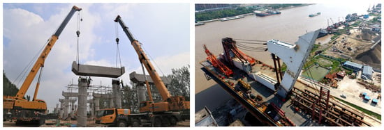
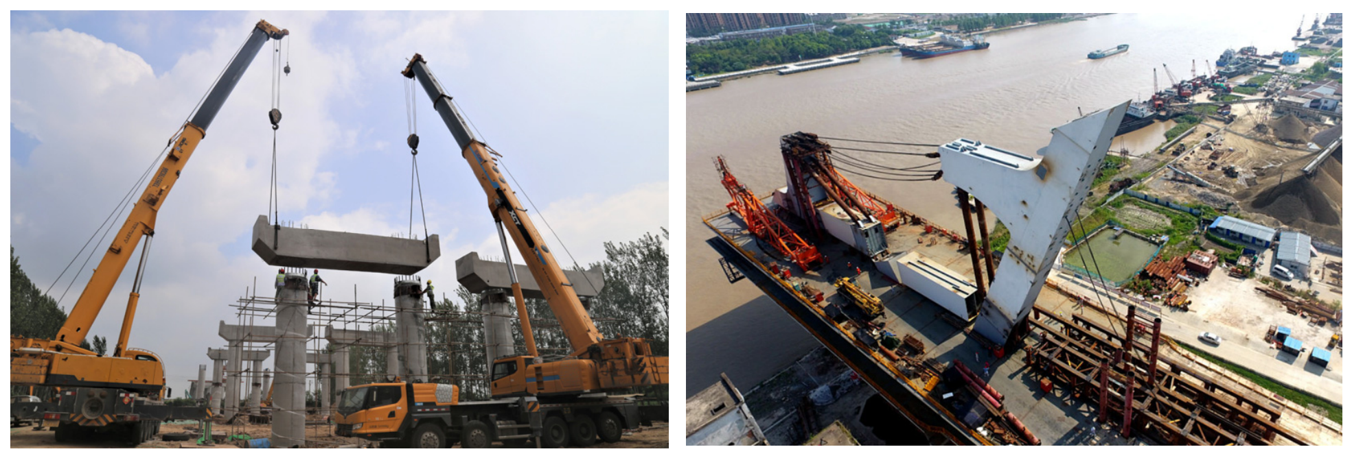
In recent years, prefabricated construction technologies have been widely promoted worldwide as an effective solution to mitigate the substantial construction waste, noise pollution, and carbon emissions associated with conventional cast-in-place construction. Prefabricated bridge systems reduce material waste through standardized manufacturing, shorten construction durations, achieve better seismic performance [1], and decrease energy consumption, thereby better aligning with the promotion of green construction. These advantages make them particularly suitable for the rapid and environmentally sustainable construction of municipal bridges in urban environments. A fully prefabricated bridge system incorporating integrally precast bridge piers and cap beams is illustrated in Figure 1. Concurrent with the development of fully prefabricated municipal bridge construction, the concept of the smart precast beam yard has also emerged and advanced rapidly [2]. During the production [3], storage, transportation, and management of precast bridge components—including bridge piers, T-girders, and cap beams—this technology effectively integrates modern digital technologies such as artificial intelligence (AI) [4] and Building Information Modeling (BIM) [5], enabling intelligent, digitalized, and refined management of precast component production facilities [6]. By leveraging these technologies, smart precast beam yards significantly enhance the efficiency, quality, safety, and cost control, but the total project efficiency is still largely restricted by the erection of those heavy precast components. To date, research on fully prefabricated bridge systems has primarily focused on high-performance materials [7,8,9,10], optimization of structural systems [11,12,13,14,15,16], and improvements in seismic performance and structural resilience [17,18,19,20,21], whereas relatively limited attention has been devoted to their construction methodologies and erection processes.
Figure 1.
Schematic illustration of a fully prefabricated municipal bridge and conventional vertical rotation erection procedure.
Municipal fully prefabricated bridge systems are typically constructed using the component lifting and erection method. Taking the Wuhan State highway G107 Project as an example (Figure 2), the bridge adopts a dual six-lane configuration with a deck width of approximately 26 m. If the cap beam were fabricated as a single precast unit, its total weight would approach 400 t. Consequently, the construction drawings suggested a segmented precast cap beam, in which the concrete cap beam is divided along the traffic direction by introducing an approximately 1.5 m wide cast-in-place closure infill. Compared with the conventional construction scheme involving the lifting and installation of an integral cap beam, the segmented cap beam approach requires more complicated procedures, including repeated attitude adjustment during lifting, cast-in-place closure infill construction, and post-tensioning operations in the air. Practical experience from similar bridge projects has shown that the alignment and attitude adjustment of segmented cap beams before final positioning often require multiple iterations, indicating that both construction efficiency and erection techniques remain to be further improved. These limitations significantly reduce the continuity and operational efficiency of the prefabricated component assembly process in smart precast beam yards.
Figure 2.
Cross-sectional schematic of the fully prefabricated bridge in the Wuhan G107 Project.
On the other hand, the vertical rotation erection method relocates the majority of cast-in-place operations to the ground level, requiring only a final rotational adjustment about a mechanical hinge during positioning. This approach offers substantial improvements in assembly efficiency and has been widely employed for the installation of precast components with complex geometries and high lifting demands, such as irregular bridge towers or skewed bridges [22]. At present, the application of vertical rotation erection methods in China is primarily limited to the construction of cable-stayed bridges with unconventional tower configurations [23,24] and similar arch bridges [25,26], while its adoption in conventional municipal bridges remains limited and is regarded as unnecessary or over-expensive unless fully prefabrication or smart beam yard technologies are required. During the vertical rotation process, the initial lifting stage represents the most critical loading condition, during which the lifting force, applied loads and damage detection on the erection system must be strictly controlled [27,28]. Once the structure reaches its final position, the load-bearing mechanism transitions to the conventional compression-dominated state. Consequently, the successful implementation of the vertical rotation method requires rigorous design of the hinge system, precise synchronized control of the lifting operation, and comprehensive analysis of the temporary structural system throughout the erection process [29].
At present, the application and investigation of the vertical rotation erection method for municipal bridges remain limited in engineering practice. Within a vertical rotation erection system, ensuring a safe and reliable rotation process is one of the primary technical challenges. This necessitates the development of a dedicated connection device between the bottom of the bridge pier and the pile cap (or footing), capable of simultaneously fulfilling multiple functions, including structural support, rotational movement, displacement restraint, alignment and positioning, and the establishment of the permanent structural connection upon completion of the erection process [30,31].
Considering the advantages of the vertical rotation erection method for the rapid, green, and safe ABC for fully prefabricated municipal bridges, this study, based on the Wuhan state highway G107 Project, proposes a vertical rotation construction method for bridge substructures. Focusing on the design of a key steel shoe installed at the bottom of the precast bridge pier, the mechanical behavior of the critical rotation point is first investigated. Subsequently, detailed finite element models are established for the principal components of the vertical rotation system, including the hinge pin and lug plates, to evaluate their structural performance. The stress distributions and ultimate stress levels of the steel shoe, lug plates, and hinge pin are examined under three representative initiation erection angles (10°, 20°, and 30°) considering below ground-level rotating hinge positions, installation beneath the operation platform as well as the unnecessarily bulky supporting system at high initial rotation angles. Based on these analyses, the feasibility of the proposed integral vertical rotation erection method is preliminarily verified among the selective scenarios. The findings are expected to facilitate a broader application of smart precast beam yards in future projects involving rapid construction of fully prefabricated municipal bridges.
2. Proposed Steps of the New Vertical Rotation Technique Using Steel Shoes
2.1. Detailed Components and Critical Steps
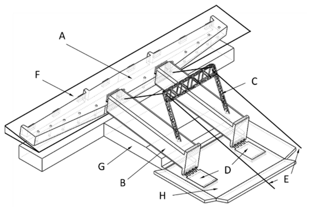
The proposed vertical rotation erection scheme for the fully prefabricated municipal bridge consists of eight primary components and five auxiliary structural elements.
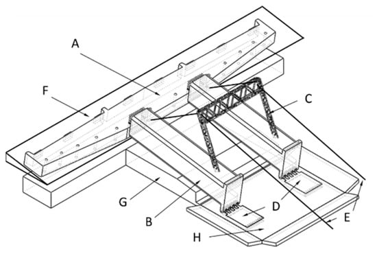
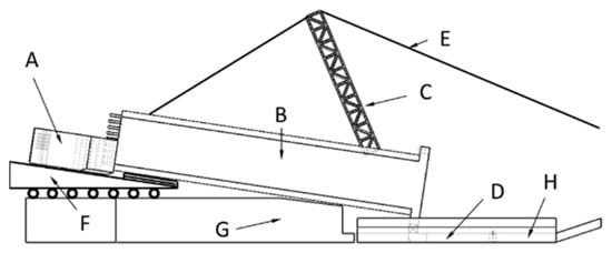
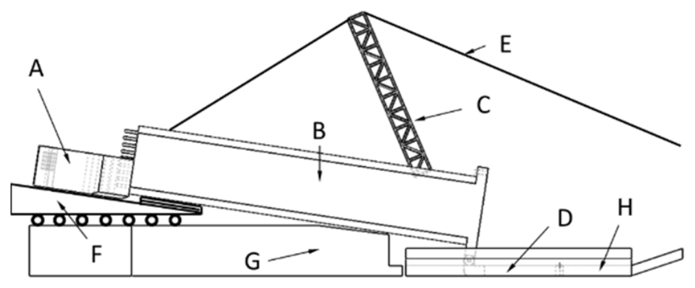
The eight primary components include the (A) cap beam; (B) precast bridge pier; (C) vertical rotation erection tower; (D) vertical rotation base; (E) vertical rotation stay cable; (F) near-ground assembly platform; (G) ground surface; and (H) top surface of the pile cap (foundation cap). As illustrated in Figure 3 and Figure 4, the bridge pier positioning device described in the following sections is installed at Location D, where it functions as a steel wedge assembly, while the steel shoe is installed at the bottom of the precast bridge pier.
Figure 3.
Schematic illustration of the horizontal assembly of the bridge for vertical rotation erection.
Figure 4.
Side view of the horizontal assembly of the bridge for vertical rotation erection.
In the proposed vertical rotation erection method, the primary structural system consists of the cap beam (A) and the precast bridge piers (B). Prior to transporting these primary components to the construction site, the vertical rotation base (D) is first accurately installed on the top surface of the pile cap (H) using pre-embedded reinforcing bars. According to the designed inclination angle of the bridge piers during horizontal assembly, the corresponding area of the ground surface (G) is then trimmed to form a planar bearing surface that satisfies the contact requirements, while the horizontal assembly platform (F) is adjusted to its predetermined position.
During the erection stage, the inclination angle of each precast bridge pier (B) is first precisely adjusted. Two precast bridge piers are subsequently lifted into position using hoisting equipment, ensuring that the hinge holes at the pier bases are accurately aligned with those of the vertical rotation base (D) to achieve secure pin connections. After confirming proper hinging, the piers are gradually lowered until the bottom surfaces come into soft contact with the prepared ground surface (G). The supporting height of the horizontal assembly platform (F) is then finely adjusted so that the contact region between the platform and the bridge pier forms a stable three-point support system. The lifting slings are released only after all three supporting points have been fully established and verified to be stable. Subsequently, the connection between the cap beam (A) and the precast bridge piers (B) is completed in accordance with the design specifications.
After the cap beam (A) and the precast bridge piers (B) have been integrally connected, the vertical rotation erection tower (C) is installed near the lower portion of the precast piers. The erection tower is designed with a movable connection at its installation node, allowing the arrangement of the vertical rotation stay cables (E) to effectively control the structural forces during the rotation process. Under the action of the anchorage tension, the stay cables drive the erection tower, together with the integrally connected cap beam and precast bridge piers, to rotate upward about the hinge located at the vertical rotation base (D). This vertical rotation continues until the interface between the precast bridge piers and the vertical rotation base achieves full contact. Before complete bearing contact is established, high-strength fastening bolts are installed at the contact interface to provide temporary restraint. The overall position and alignment of the assembled structure are then finely adjusted, after which the precast bridge piers are permanently secured to the vertical rotation base using the fastening bolts, thereby ensuring structural integrity and satisfying the design requirements. The overall construction procedure is illustrated in the corresponding figure.
Upon completion of the vertical rotation erection process, the vertical rotation erection tower (C), vertical rotation stay cables (E), and horizontal assembly platform (F) are dismantled and transported to the next construction location for reuse in subsequent erection operations.
2.2. Important Features
This construction method can substantially reduce disruptions to the traffic, underground utilities, and surrounding buildings beneath and adjacent to the bridge, making it particularly suitable for urban environments with limited construction space. By transferring most of fabrication and assembly operations to ground level and adopting an integral lifting and vertical rotation procedure for final positioning, the method effectively ensures the geometric accuracy and surface quality of complex structural components. Furthermore, it significantly reduces or eliminates conventional labor-intensive operations, such as high-elevation welding, large-volume formwork installation and concrete casting, and the construction of temporary support bents, thereby improving construction efficiency and safety.
2.3. Design of the Steel Shoe
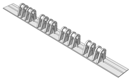
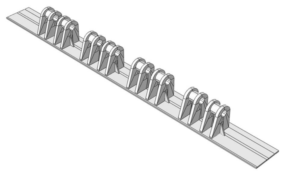
As illustrated in Figure 5 and Figure 6, the steel shoe vertical rotation system primarily consists of a hinge pin, lug plates, steel grating plates, stiffening plates, and top and bottom steel plates. In accordance with the design specifications, the hinge pin has a diameter of 60 mm. The top steel plate measures 1860 mm × 1860 mm, while the bottom steel plate measures 2200 mm × 2000 mm, with its width reduced by 200 mm to accommodate the rotational hinge. The internal framework comprises steel grating plates welded between the top and bottom steel plates to form the primary load-carrying structure. The four rotational holes in Figure 5 have overall dimensions of 145 mm × 145 mm × 100 mm and contain a 65 mm diameter central hole. Its 5 mm diametral clearance is designed to ensure smooth rotational movement during erection and is not an optimized value. Each out of eight lug plates consists of two 25 mm thick steel panels and a 65 mm diameter central hole, while the hole is surrounded by a 75 mm length outwardly extended annular section with sufficient thickness, such as 10 mm, and each hinge pin rod is supported by two lug plates, as illustrated in Figure 6. All structural components are supposed to be connected by full welding. Upon completion of the vertical rotation erection of the bridge pier, the connection between the steel shoe and the vertical rotation base is secured using enough high-strength bolts.
Figure 5.
Steel shoe.
Figure 6.
Base rotation device (four lug plates).
3. Static Analysis of Steel Shoes
3.1. Force Analysis of the Rotation Point
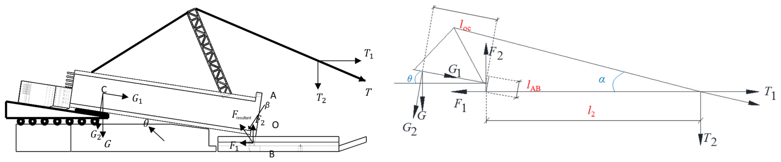
The integrally assembled cap beam and two precast bridge piers have a total weight of approximately 330 t, in which the weight of the cap beam dominates as it largely modifies the gravity center of the combined body. The steel shoe is designed with a bottom plate measuring 2200 mm × 2000 mm and a top plate measuring 1860 mm × 1860 mm. Each bridge pier has a height of 8 m, and the pulling point used for the vertical rotation operation is located 25 m from the bridge pier. Based on a simplified centroid calculation, the center of gravity of the assembled structure is estimated to be approximately 7 m above the top surface of the steel shoe (bridge pier height is 8 m). The initial inclination angle of the bridge pier, denoted by θ, is designed as 10°. The initial lifting stage of the vertical rotation process represents the most critical loading condition, with the most unfavorable stress concentration occurring at the connection between the steel shoe, lug plates, and hinge pin. To facilitate the mechanical analysis, the structural components illustrated in Figure 4 are simplified, and the corresponding idealized mechanical model used for the force analysis is established, as shown in Figure 7.
Figure 7.
Simplified free-body diagram of forces acting at the steel shoe rotation point.
Based on the equations of static equilibrium and moment equilibrium, the following governing equations can be derived:
where G1 is the component of the total gravitational force acting along the longitudinal axis of the bridge pier;
G1lOB + T2l2 = G2lOC
T2 = (G cos θ lOC − G sin θ lOB)/l2
F2 = G + T2
T1 = F1 = T2/tan α
G1 = G sin θ
G2 = G cos θ
g = 9.8 m/s2
G2 is the component of the total gravitational force perpendicular to the bridge pier;
lAB is the length of the bottom plate of the steel shoe;
lOB is the moment arm of the gravitational force component, which is approximately equal to one-half of the length of the bottom plate of the steel shoe;
lOC is the vertical distance from the overall center of gravity to the steel shoe;
T2 is the component of the pulling force T perpendicular to the horizontal plane;
T1 is the component of the pulling force T parallel to the horizontal plane;
l2 is the distance from the lifting point to the bottom of the steel shoe;
F1 is the horizontal reaction force exerted by the lug plates on the steel shoe;
F2 is the corresponding vertical reaction force;
Fresultant is the resultant force from the combination of F1 and F2;
β is the angle between Fresultant and F2;
θ is the initial inclination angle of the bridge pier;
φ is β + θ, representing the angle between Fresultant and shear force V;
α is the inclination angle of the pulling cable correlated to the angle θ, which is determined by a given height of the erection tower as 7 m. By substituting the assumed geometric and loading parameters into the above equations, the resultant force acting at the rotation point can be obtained.
3.2. Shear Analysis of the Bottom Section of the Pier
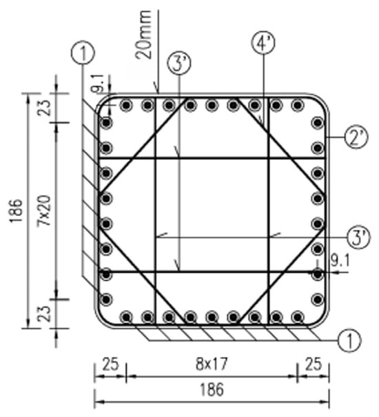
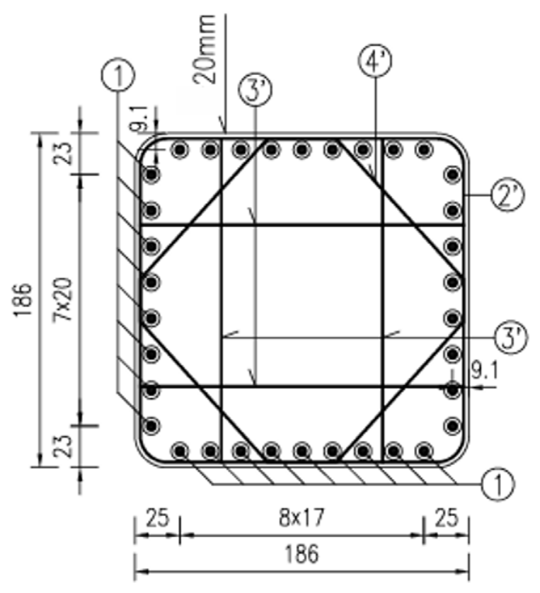
During the vertical rotation erection of the bridge pier, the interface between the bridge pier and the steel shoe represents another critical region requiring careful evaluation. Throughout the rotation process, the applied shear force is jointly resisted by the concrete and the embedded reinforcing bars. Given that the steel shoe is supposed to be firmly connected to the embedded reinforcement and bottom concrete following casting procedures, the steel shoe is regarded as fixed to the bridge bottom. The arrangement of the reinforcing bars at the pier–steel shoe interface is illustrated in Figure 8.
Figure 8.
Reinforcement layout at the base of the bridge pier.
The contact area of the top surface of the steel shoe is approximately 3.46 m2 due to the side length of the square shape at 1.86 m. Based on mechanics principles, the contact stress can be calculated as follows:
V = Fresultant cos φ
φ = β + θ
V = GshearAγ
The calculated shear stress using a simplified pure concrete section [32,33] is 0.5 MPa < 3.0 MPa (shear capacity), equivalent to γ = 4.2 × 10⁻⁵, indicating that the C40 concrete probably remains within the initial linear elastic stage with enough margin.
4. Stress Distribution on Steel Shoes During Vertical Rotation
4.1. Establishment of the FEA Model
This study employs the ABAQUS finite element software to perform numerical simulations and parametric analyses of the steel shoe and the rotational hinge assembly. Based on the theoretical analyses presented in the preceding sections, the initial stage of bridge pier rotation may be identified as the most critical loading condition. Accordingly, three representative initial rotation angles, namely 10°, 20°, and 30°, are considered as separate analysis cases. By comparing the numerical results obtained under these three loading scenarios, the rationality of the proposed analytical method is verified, and the most representative results are selected for subsequent discussion.
The three-dimensional geometric model is first established using SolidWorks. The completed geometry is then exported in STEP format and imported into the Part module of ABAQUS.
The reported stresses in following sections are integration-point (Gauss point) values extracted directly from the ABAQUS output database (ODB). No nodal extrapolation or nodal averaging was applied to the reported peak values, while the tabulated numerical values are directly adopted from recorded ones in the legend.
4.1.1. Part and Material Properties
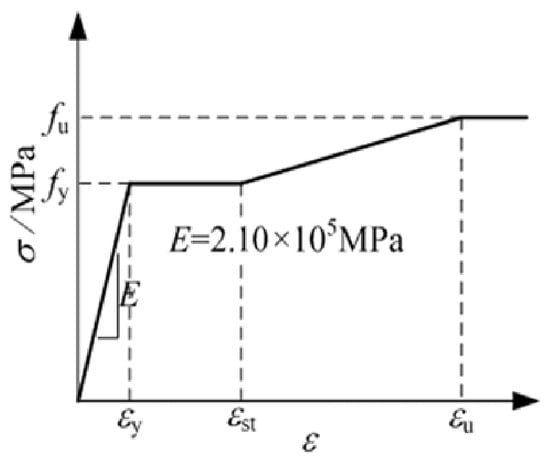
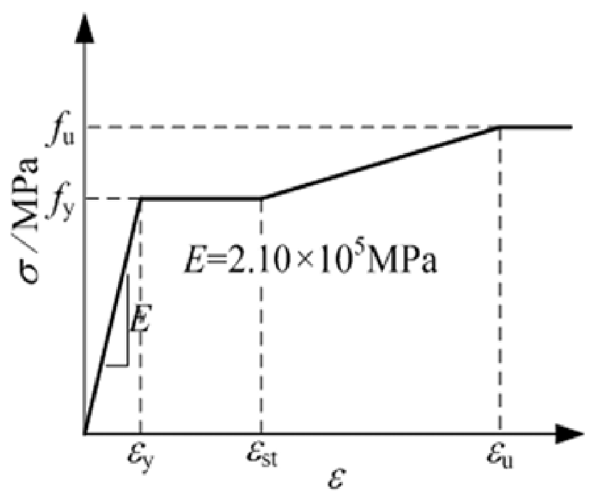
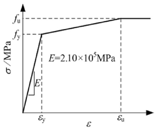
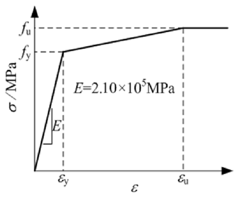
In the finite element model, the hinge pin is assumed to be fabricated from 40Cr steel, while the lug plates and all remaining steel components are modeled using Q345 structural steel; the properties of two types of steel materials are listed in Table 1 using the following three calculation Equations (11)–(13).
σtrue = σengineering × (1 + εengineering)
εtrue = ln(1 + εengineering)
εplastic, input = εtrue − σtrue/E
Table 1.
Input material properties.
The contact interface between the hinge pin and the lug plates is defined as a surface-to-surface contact. In the normal direction, hard contact is adopted to prevent interpenetration, whereas the tangential behavior is modeled using a Coulomb friction formulation with a friction coefficient of 0.5 between the steel surfaces according to related references and BS EN 1993-1-8:2005 code [34,35,36]. Figure 9 and Figure 10 present the constitutive models adopted for the two materials.
Figure 9.
Q345 constitutive model.
Figure 10.
40Cr constitutive model.
4.1.2. Boundary and Loading Conditions
In the numerical simulation, the boundary conditions and loading conditions have a significant influence on the analysis results. Improper definitions may not only affect the accuracy of the numerical results but may also lead to convergence failure. Accordingly, the boundary conditions are established to accurately represent the actual vertical rotation erection process. A fully fixed constraint is applied to the bottom surface of the steel shoe, while the base of the rotational hinge assembly is also assigned a fully fixed boundary condition. The hinge pin is constrained using prescribed displacement and rotational boundary conditions.
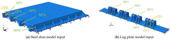
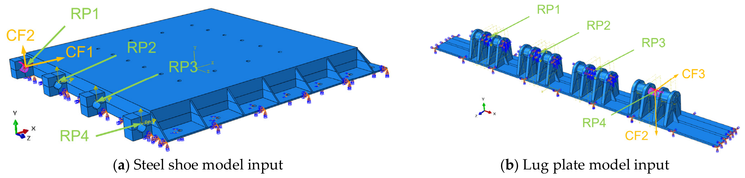
In the Constraint Manager, the reference points RP-1 to RP-4 are created at the loading locations and coupled to the corresponding structural regions using kinematic coupling constraints. In addition, the hinge pin is partitioned to facilitate contact definition, and surface-to-surface contact is established between the hinge pin and the lug plates. The detailed boundary and representative loading conditions of ABAQUS input models are given in Figure 11.
Figure 11.
Boundary and representative loading conditions of ABAQUS input models.
Considering the geometric characteristics of the structure and the complex contact behavior of the touching component, a smooth loading amplitude with refined steps is adopted for improving numerical stability.
4.1.3. Mesh Sensitivity Analysis
Mesh discretization plays a critical role in finite element analysis and can significantly influence the accuracy and reliability of the numerical results. In this study, a global mesh size of approximately 25–30 mm is adopted, and the model is discretized using ten-node tetrahedral elements C3D10 instead of hexahedral counterparts due to convergence efficiency. To improve the accuracy of the stress analysis in the critical regions, local mesh refinement is performed at the interfaces between the steel shoe, lug plates, and hinge pin. In particular, these connection regions are carefully partitioned prior to meshing to ensure sufficient mesh quality and density, thereby enabling an accurate prediction of the stress distribution and structural response at the critical load-transfer locations.
A mesh sensitivity analysis is subsequently conducted in ABAQUS to evaluate the influence of mesh density on the numerical results. The testing models for mesh sensitivity analysis used the exact model illustrated in Figure 11. The results are summarized in Table 2 and Table 3. As the mesh is progressively refined, the calculated responses exhibit clear convergence, indicating that the adopted mesh densities provide sufficient numerical accuracy. Based on the convergence analysis, finite element models comprising 241,234 elements for the steel shoe and 22,960 elements for the lug plates are selected for the subsequent simulations in all three cases.
Table 2.
Mesh sensitivity analysis of the steel-shoe/rotational-hole junction under 10° condition.
Table 3.
Mesh sensitivity analysis of the pin–lug contact region under 10° condition.
4.1.4. Independent Mechanical Verification
The load-transfer mechanism is rather simple, as indicated in Figure 3 and Figure 4, where the large force from rotation operation is performed as a shear force imposed onto the hinge pins, further transferring to the lug bearing pairs at both sides of the pin through contact.
The total reaction forces (vertical component) extracted from the ABAQUS model at the fixed boundary have been compared with the analytical vertical forces calculated from Equations (1)–(6). The detailed differences shown in Table 4 are less than 1.5% for all three loading cases, confirming that the FE model correctly represents the global force equilibrium.
Table 4.
Comparison of FE reaction force versus analytical force.
The maximum shear force per pin is approximately 648 kN (from Table 5 Case 1 at 10°). For a 60 mm diameter 40Cr hinge pin, the nominal shear stress is τ = Fshear/(π/4 × 602) = 229 MPa, which is well below the shear yield strength. Given the dimensions of a pair of lug bearings, four 25 mm × 200 mm bearing feet support the aforementioned maximum shear force on a pin, and the resulted net-section compressive stress is σ = Fshear/(25 × 200 × 4) = 32 MPa, which is also well below the shear yield strength. Basic mechanical verification indicates that the designed hinge pin and lug plates are feasible.
Table 5.
Loading conditions of the steel shoe under the three loading cases.
4.2. Numerical Results in Three Rotation Conditions
Three representative loading cases are considered in this study to perform static finite element analyses using ABAQUS. Among them, the initiation stage of the vertical rotation process represents the most critical loading condition. During this stage, the abrupt change in the structural load path causes the rotational hinge region of the steel shoe to become the most vulnerable part of the system, where pronounced stress concentrations and relatively large local deformations are expected.
Based on the geometric configuration of the erection system, the actual rotation angles of the bridge pier are taken as 10°, 20°, and 30°, corresponding to α values of 15°, 17°, and 19°, respectively, as illustrated in Figure 7. The rotational loads for the three loading cases are subsequently calculated according to Equations (1)–(8), and the resulting loading parameters are summarized in Table 5 and Table 6. For the record, the resultant force is calculated from the total weight, consisting of a heavy cap beam and two piers, CF1 and CF2 are 1/8 of the horizontal and vertical forces in the steel shoe, respectively, while the input CF2 and CF3 in Table 6 are slightly different because the local coordinate system is slightly tilted in the lug plate and hinge assembly due to initial rotation angle and resultant force vector. To calculate the horizontal/vertical force in the steel shoe, the initial rotation angle and the Fresultant vector should be considered during a nodal force decomposition. The contour scales of result figures are different, and the corresponding yield stress is listed in Table 1.
Table 6.
Loading conditions of the lug plate and hinge assembly under the three loading cases.
4.2.1. Stress and Disp. Distribution Under Initial Rotation Angle of 10°
Case 1 corresponds to an initial bridge pier inclination angle of 10°. The resultant load is assumed to be uniformly distributed over the rotational hinge region of the steel shoe, and the calculated concentrated loads, CF1 = 434,816 N and CF2 = 489,229 N, are applied to establish the static analysis step. The stress response of the steel shoe at the initiation stage of the vertical rotation process is presented in Figure 12.
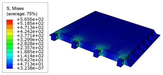
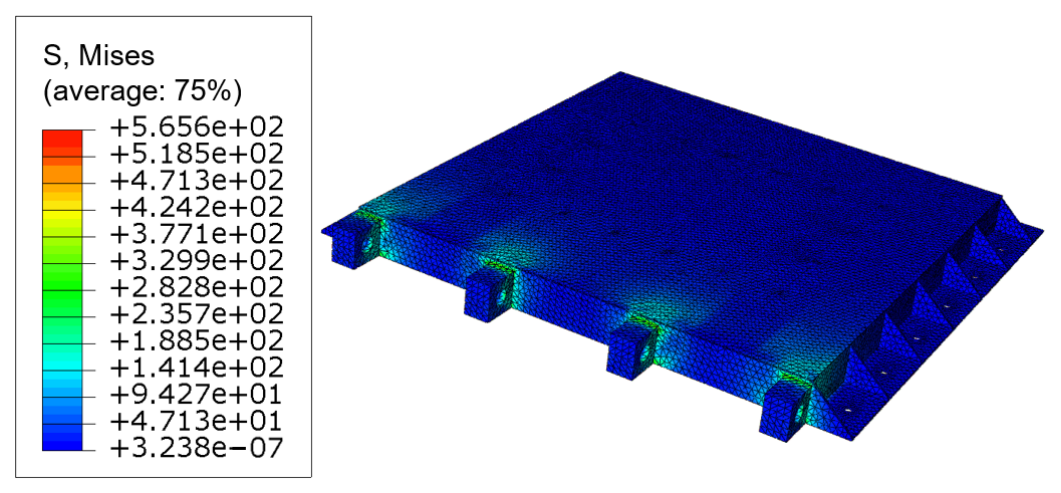
Figure 12.
Numerical results of the steel shoe under Case 1 (unit-MPa).
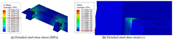
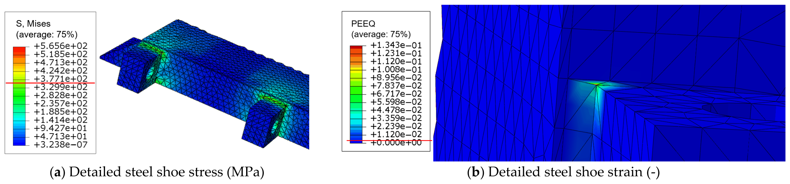
Under Case 1, the maximum stress in the steel shoe reaches 565.6 MPa, occurring at the junction between the rotational hinge and the main body of the steel shoe. In contrast, the representative stress, i.e., the dominant stress over the majority of the affected elements, is approximately 329.9 MPa. The elevated stress is primarily attributed to local stress concentration at the hinge connection, with a yielded volume of the whole steel shoe elements at lower than 0.01% (23 out of 240,000 more elements). The maximum displacement is 0.6151 mm, while the obtained peak strain (13.4% < 16.3%) stays within an acceptable range. As shown in Figure 13, the stress/strain concentration is confined to the rotational hinge region of the steel shoe, where the red line in the legend indicates the yield stress level. The area where the stress/strain exceeds the yield value is extremely limited, and the peak surface stress is localized to only a few finite points, indicating that the high-stress/extreme-strain region is highly localized rather than widely distributed. Despite the limited influence region, as shown in Figure 13, the maximum stress in the steel shoe—565.6 MPa—exceeds the yield strength of Q345 steel (360.3 MPa) and is approaching the ultimate tensile strength given in Table 1 (595.3 MPa), indicating the selection of an initiation erection angle at 10° to be avoided or conducted with caution.
Figure 13.
Stress/strain distribution in steel shoe under Case 1 with yield red line displayed.
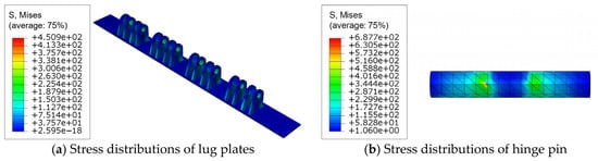
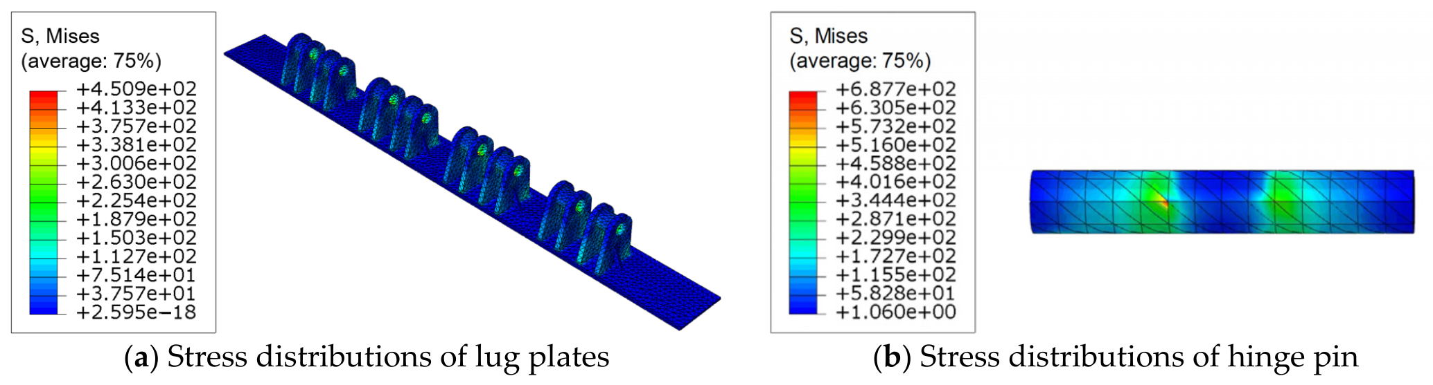
Under Case 1, the resultant load is assumed to be uniformly distributed over the hinge pin, and the calculated concentrated loads, CF2 = 513,436 N and CF3 = 405,948 N, are applied to establish the static analysis step. The resulting stress responses of the lug plates and the hinge pin at the initiation stage of the vertical rotation process are presented in Figure 14 and Figure 15, respectively.
Figure 14.
Stress distributions of critical components under Case 1 (unit-MPa).
Figure 15.
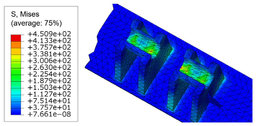
Local stress distribution at concentration region of lug plates under Case 1 (unit-MPa).
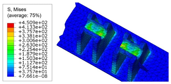
Analysis of the stress responses of the lug plates and hinge pin during the vertical rotation process indicates that, under Case 1, the maximum stress in the lug plates reaches 450.9 MPa, occurring at the contact interface between the lug plates and the hinge pin. In the remaining regions, the stress is approximately 300.6 MPa. The elevated stress at the contact interface is attributed to local stress concentration. Although the peak stress exceeds the yield stress of the material, it remains below its ultimate strength, indicating that yielding is confined to a highly localized region, with a yielded volume of the whole lug plates elements at 0.15% (35 out of 21,000 more elements).
For the hinge pin, the maximum stress is 687.7 MPa, which likewise occurs at the contact interface with the lug plates. The stress in most other regions is approximately 458.8 MPa. The stress distribution is relatively uniform outside the contact region, and the peak stress remains below the yield stress of the 40Cr steel, indicating that the hinge pin remains within the elastic range under this loading condition.
4.2.2. Stress Distribution Under Initial Rotation Angle at 20° and 30°
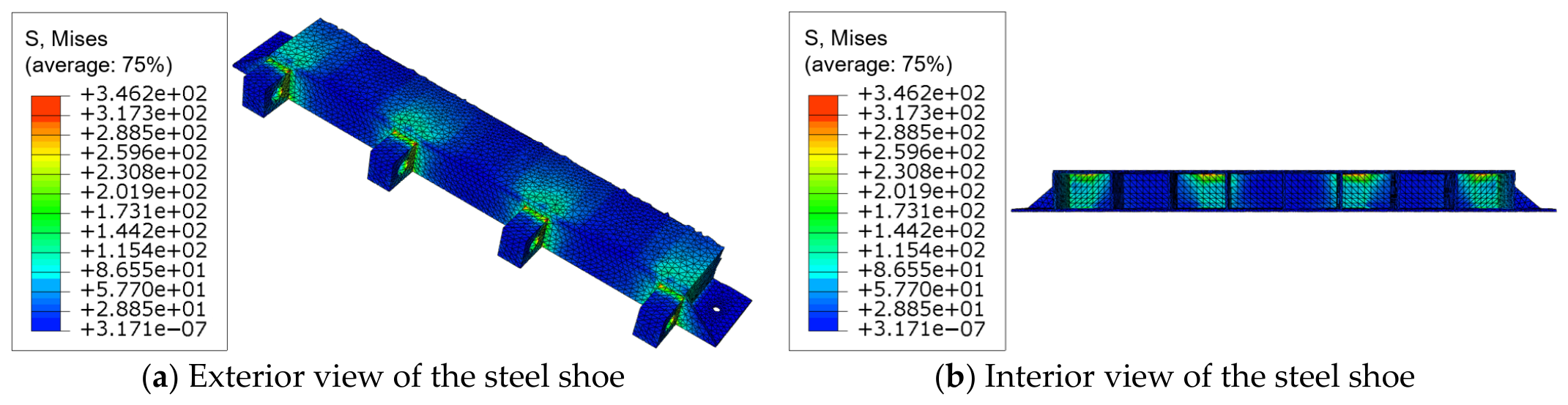
Case 2 and 3 correspond to initial bridge pier inclination angles of 20° and 30°. The resultant loads are assumed to be uniformly distributed over the rotational hinge region of the steel shoe, and the calculated concentrated loads are applied according to Table 6. The resulting stress responses of the steel shoe at the initiation stage of the vertical rotation process are presented in Figure 16, Figure 17, Figure 18 and Figure 19.
Figure 16.
Local stress distribution at the rotational hinge region of the steel shoe under Case 2 (unit: MPa).
Figure 17.
Stress distributions of critical components under Case 2 (unit: MPa).
Figure 18.
Stress distribution at the rotational hinge region of the steel shoe under Case 3 (unit: MPa).
Figure 19.
Stress distributions of critical components under Case 3 (unit: MPa).
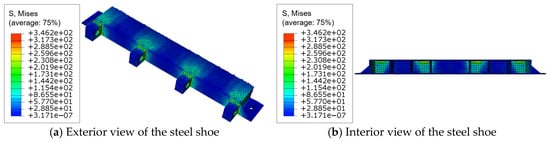
Under Case 2, the maximum stress in the steel shoe is 346.2 MPa, which is significantly lower than the corresponding value of 565.6 MPa (39% reduction) obtained in Case 1. As in the previous case, the maximum stress occurs at the junction between the rotational hinge and the main body of the steel shoe. In the remaining regions, the representative stress is approximately 230.8 MPa, which is well below the allowable stress range of the material. These results indicate that increasing the initial rotation angle from 10° to 20° effectively reduces the stress concentration in the critical hinge region of the steel shoe during the initiation stage of the vertical rotation process.
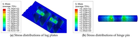
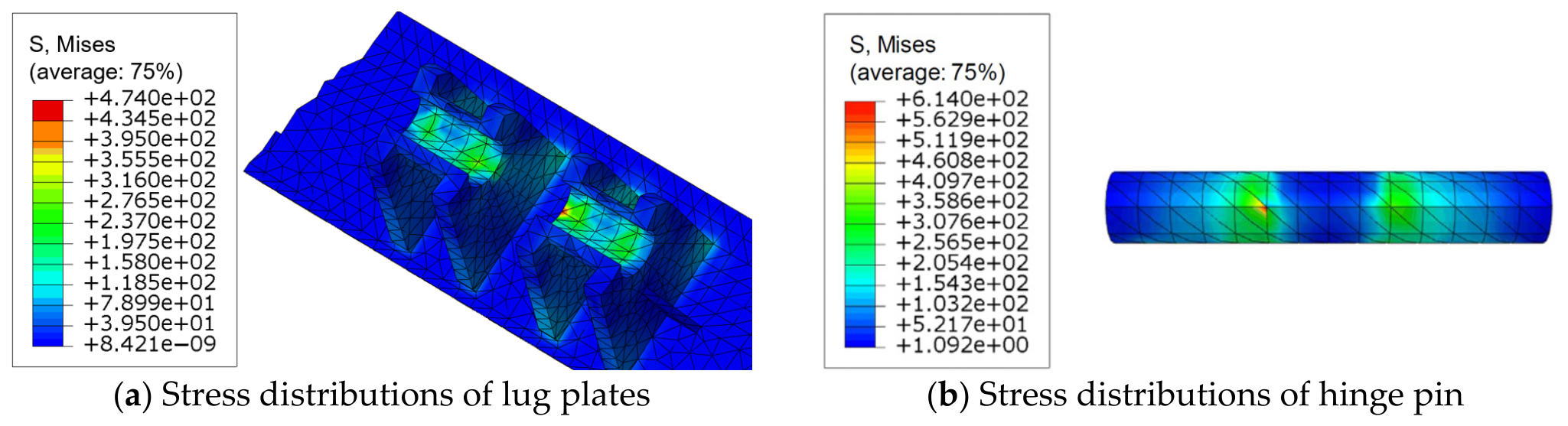
Under Case 2, the resultant load is assumed to be uniformly distributed over the hinge pin. The resulting stress responses of the lug plates and the hinge pin at the initiation stage of the vertical rotation process are presented in Figure 17.
Analysis of the vertical rotation response of the lug plates and hinge pin indicates that, under Case 2, the maximum stress in the lug plates reaches 474 MPa, occurring at the contact interface between the lug plates and the hinge pin. This value is slightly higher than the corresponding maximum stress of 450.9 MPa obtained in Case 1. In the remaining regions, the representative stress is approximately 316.0 MPa, indicating that stress concentration remains pronounced at the contact zone.
For the hinge pin, the maximum stress is 614 MPa, which is slightly lower than the 687.7 MPa observed in Case 1. The peak stress also occurs at the contact interface between the lug plates and the hinge pin, while the representative stress in other regions is approximately 358.6 MPa. The stress distribution outside the contact area remains relatively uniform, and the peak stress is still below the yield strength of hinge pin material, indicating that the hinge pin continues to operate within the elastic range under Case 2.
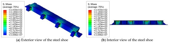
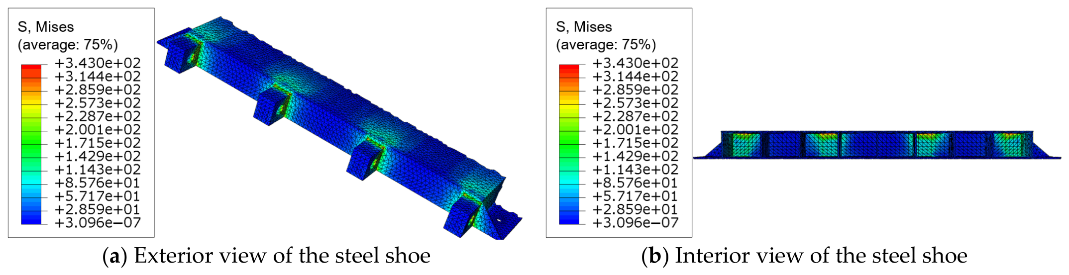
Under Case 3, the maximum stress in the steel shoe reaches 343 MPa as indicated in Figure 18. Compared with the previous cases, the reduction in maximum stress with an increasing initial inclination angle is not significant. In the remaining regions, the representative stress is approximately 228.7 MPa, which is well below the allowable stress range of the material. These results indicate that increasing the initial inclination angle from 20° to 30° has a limited influence in reducing the peak stress in the steel shoe, with the rotational hinge region remaining the governing stress concentration zone during the initial rotation stage.
Under Case 3, the resulting stress responses of the lug plates and the hinge pin at the initiation stage of the vertical rotation process are presented in Figure 19. An identical stress distribution pattern is observed between Case 2 and Case 3. The maximum stress in the lug plates is comparable with that under Case 2, leaving the maximum stress in the hinge pin slightly reduced from 614 MPa to 539.1 MPa. The stress distribution outside the contact zone remains relatively uniform, and the peak stress is still below the yield strength of the hinge pin material, indicating that the hinge pin continues to behave within the elastic range under this loading condition.
4.3. Results Trends Under Increasing Initial Rotation Angles
Although the maximum stresses in both the steel shoe and the lug plates exceed the material yield strength during the initial rotation stages with inclination angles ranging from 10° to 30°, these peak values occur only at a limited number of elements due to local stress concentration and do not affect the overall safety of the vertical rotation process. The variation trends are summarized in Table 7, where the percentages in brackets indicate variations between the current case and the left case. With an increasing initial rotation angle, the maximum stresses in both the steel shoe and the hinge pin show a decreasing trend due to lever arm effect, especially when the initial angle is 10° and the (horizontal) lever arm is noticeably small, amplifying the shear force (horizontal reaction force) from the pulling system. Although the vertical reaction force may be intensified as the initial rotation angle increases, the vertical lever arm also decreases. Apparently, the resultant force at the rotating point is dominated by the pulling force variation from the cable system. However, as the initial rotation angle increases, the rate of reduction gradually diminishes. In contrast, the maximum stress in the lug plates exhibits a slight increasing trend with an increasing initial inclination angle, although the overall variation remains relatively small. From a practical engineering perspective, it is therefore unnecessary to pursue excessively large initial rotation angles solely for the purpose of reducing structural stresses, as the improvement in stress reduction becomes marginal beyond a certain range.
Table 7.
Max/Representative unfavorable stresses during vertical rotation (MPa).
5. Discussion
The current study focuses on the static stress distribution to establish baseline structural behavior for the proposed steel shoes under rather idealized conditions. Eccentricities from cable installation and transient dynamic loads (e.g., sudden tensioning/release) were excluded due to their complexity and dependence on site-specific factors. It should be noted that real applications regarding the proposed vertical rotation technique should always take into account the possible detrimental dynamic-amplification effect from those site-specific factors together with a thorough validation against experimental data.
The integrated vertical rotation construction method proposed in this study does not include verification of the erection tower system, temporary lifting hardware, welding, bolts and ground pulling/reaction devices. The erection tower system actually has an important role in ensuring the stability of the whole rotating entity, whose stiffness and self-weight should be carefully considered during thorough design of the proposed construction scheme. Future applications should therefore be based on the numerical analysis results presented in this paper, while comprehensively considering other practical construction parameters, and should be implemented with appropriate engineering caution with an appropriate selection of the safety factor.
Fully fixed boundary conditions widely adopted in this paper would be idealistic, and in real situations, the boundary condition is normally a bit flexible, and the resultant stresses would be slightly reduced. This boundary setting is acceptable since making it fixed is more conservative, and the proposed numerical simulation is a simplified version.
The supporting platform beneath the heavy bridge substructure assembly should be capable of providing extra horizontal reaction force at high initial rotation angles. Further increasing the initial rotation angle would inevitably complicate the design of this supporting platform.
For all three loading cases, the high concentrated stresses in the steel shoe drop quickly between adjacent hinge connections, indicating that there is still room affordable to accommodate more hinges. It is suggested to increase the number of hinges to alleviate the stress concentration effect and achieve a better service performance in future updates.
Future work will focus more on the practicality of the proposed ABC technique in terms of gesture control during rotating process, easy circulation of the auxiliary equipment, and a convenient fastening method of the rotate-in-place bridge feet.
Although future practices will probably yield different drawings or geometries, the changes in the bridge pier design of municipal viaducts are quite limited, so the steel shoe and calculation steps in this paper can still be beneficial to those exemplifications.
6. Conclusions
Based on the actual Wuhan G107 project and geometric dimensions of prefabricated components in its smart precast yard, a vertical rotation construction method for bridge substructures is proposed for better Accelerated Bridge Construction. A detailed numerical analysis of the critical rotation zone is conducted based on the key steel shoe design at the bottom of the precast bridge pier. A refined finite element model of key rotation components is established in the ABAQUS platform. Three initial rotation angles, namely 10°, 20°, and 30°, are preliminarily considered to investigate the stress distributions of the steel shoe, lug plates, and hinge pin. The following conclusions can be drawn:
- (1)
- An integrated vertical rotation construction method is proposed based on a real municipal bridge project adopting prefabricated bridge columns and cap beams, which reduces the need for high-altitude prestressing operations, probably achieving effectively optimized handling of heavy structural components.
- (2)
- Under all vertical rotation loading cases, the most unfavorable stresses in both the steel shoe and the hinge pin are observed under the 10° initial rotation angle case 1, where pronounced stress concentration effects are evident at the hinge connection. Only the maximum stress in the steel shoe as 565.6 MPa is approaching the ultimate tensile strength of 595.3 MPa, indicating that the selection of an initiation erection angle at 10° should be avoided.
- (3)
- Compared with the 10° rotation scenario, increasing the initial rotation angle to 20° reduces the most critical stress inside the steel shoes by up to 39%, while the reduction is largely reduced to 1% from 20° to 30°. Considering the unnecessary demand on the bulky support platform underneath at higher initial rotation angles, an initial rotation angle at 20° is superior among the three adopted representative conditions and may serve as a reference for preliminary design.
Author Contributions
Conceptualization, Y.L. (Yingqi Liu); Methodology, X.S. and Y.L. (Yingqi Liu); Software, Y.L. (Yingqi Liu); Validation, Y.L. (Yanxiong Li), S.G., X.S. and Y.L. (Yingqi Liu); Formal Analysis, Y.L. (Yingqi Liu); Investigation, Y.L. (Yanxiong Li), W.W. and X.S.; Resources, W.W. and S.L.; Data Curation, Y.L. (Yingqi Liu); Writing—Original Draft, Y.L. (Yanxiong Li), S.G., X.S. and Y.L. (Yingqi Liu); Writing—Review and Editing, Y.L. (Yingqi Liu); Supervision, Y.L. (Yanxiong Li), S.G., S.L., J.W. and Y.L. (Yingqi Liu); Project Administration, Y.L. (Yanxiong Li), S.G. and B.Y.; Funding Acquisition, Y.L. (Yanxiong Li), S.G., W.W., S.L., B.Y., B.W. and J.W. All authors have read and agreed to the published version of the manuscript.
Funding
This research was funded by the Scientific Research and Development Project of China Railway Group Limited (2023-Special Class-02). Partial support is also provided by the Major Special Project for Scientific and Technological Research and Development of the China Construction Third Engineering Bureau (CSCEC3B-ZD-2024-01) and the Open Research Project of the Key Laboratory of Beijing University of Technology (2026-04).
Data Availability Statement
The original contributions presented in this study are included in the article. Further inquiries can be directed to the corresponding author. Some sharable data can be found in the links below: https://sandbox.zenodo.org/records/599935?token=eyJhbGciOiJIUzUxMiJ9.eyJpZCI6IjIxOTc2YWU3LWY3Y2YtNDFhYS1hODA2LTcyYzg2MDUyOGNlYSIsImRhdGEiOnt9LCJyYW5kb20iOiIzZWEyNzM5NTZmNzY0OGU1YmQwMGM4MmE5M2QxZmZhNiJ9.lsy4HXilyoUE-N-9d2ms8Ayjuf6Aq5yZwXzuAXyAodmf7H-ymiQ-71SW6RxScCEBLLI_LezdVS3Cb-WBHQvaOQ (accessed on 20 September 2026).
Conflicts of Interest
Authors Yanxiong Li, Shiyu Guan, Songwei Li, Bin Yan and Ben Wang were employed by the company China Construction Third Engineering Bureau Group Co., Ltd. Author Wei Wang was employed by the company China Railway Major Bridge Reconnaissance & Design Institute Co., Ltd. Author Xi Sun was employed by the company China Railway Zhengzhou Bureau Group Co., Ltd. Authors have received Funding from Scientific Research and Development Project of China Railway Group Limited. The remaining authors declare that the research was conducted in the absence of any commercial or financial relationships that could be construed as a potential conflict of interest.
References
- Neupane, S.; Pantelides, C.P. Seismic Design and Fragility of Self-Centering Bridge Bent with Replaceable Stretch Length Anchors. Earthq. Eng. Struct. Dyn. 2025, 54, 1433–1453. [Google Scholar] [CrossRef] [Scilit]
- Wang, J.; Wang, X.; Dong, S. Construction of MBSE-based smart beam yard system. In Proceedings of the International Conference on Smart Transportation and City Engineering (STCE 2023), Chongqing, China, 16–18 December 2023; pp. 387–394. [Google Scholar]
- Guan, S.; Duan, X.; Wang, Y.; Tang, H.; Li, S.; Zhou, W.; Tang, B.; Liu, Y. Intelligent Stirrup Bending and Welding Technology for Reinforcement Processing in Smart Girder Yards. Buildings 2025, 15, 4075. [Google Scholar] [CrossRef] [Scilit]
- Kolangiammal, S.; Prabha, S.; Sivalakshmi, P.; Kalaichelvi, S.; Sujatha, S. Transforming yard management for optimizing efficiency through IoT and AI integration. In Proceedings of the 2024 8th International Conference on I-SMAC (IoT in Social, Mobile, Analytics and Cloud) (I-SMAC), Kirtipur, Nepal, 3–5 October 2024; pp. 218–223. [Google Scholar]
- Gao, M.Y.; Han, C.; Yang, Y.; Tiong, R.L.K. Integration of BIM and RFID-Sensing Technology for Automated Progress Monitoring in Modular Construction. In Proceedings of the 41st International Symposium on Automation and Robotics in Construction, Lille, France, 3–5 June 2024. [Google Scholar]
- Tan, Y.; Yu, D.; Yang, S.; Gai, T.; Wang, C. Precast concrete component yard layout optimization considering safety and efficiency. J. Asian Archit. Build. Eng. 2024, 24, 2800–2816. [Google Scholar] [CrossRef] [Scilit]
- Kim, D.; Jeon, C.-H.; Park, K.-T. Cyclic Performance of Prefabricated Bridge Piers with Concrete-Filled Steel Tubes and Improved Bracing Connection Detail. Appl. Sci. 2024, 14, 11810. [Google Scholar] [CrossRef] [Scilit]
- Ni, Y.; Hu, M.; Jia, Z.; Han, Q. Shear Behavior of Y-Shaped Perfobond Rib Shear Connector with UHPC Grout. J. Struct. Eng. 2024, 150, 04024102. [Google Scholar] [CrossRef] [Scilit]
- Liu, Y.Q.; Liang, F.; Au, F.T.K. Experimental study of durable low-friction concrete contacts for precast segmental columns with resettable sliding joints. Constr. Build. Mater. 2022, 318, 126192. [Google Scholar] [CrossRef] [Scilit]
- Zhu, H.; Xu, P.; Liu, Y.; Chen, Y.; Li, J. Flexural capacity of reinforced concrete members strengthened with stainless steel casing. Thin-Walled Struct. 2025, 215, 113554. [Google Scholar] [CrossRef] [Scilit]
- Liu, Y.Q.; Liang, F.; Au, F.T.K. Precast segmental bridge columns with resettable sliding joints —— An inspiration from ancient Chinese pagodas. Structures 2021, 33, 615–626. [Google Scholar] [CrossRef] [Scilit]
- Liu, Y.; Yuan, Y.; Liang, F.; Au, F.T.K. Resetting response of precast segments with gently keyed interface under seismic action. Earthq. Eng. Struct. Dyn. 2020, 50, 601–618. [Google Scholar] [CrossRef] [Scilit]
- Liu, Y.; Li, H.; Liang, F.; Bao, Y.; Wang, W.; Au, F.T.K. Conceptual shaking table tests for resilient segmental bridge columns with resettable sliding joints. Eng. Struct. 2024, 317, 118596. [Google Scholar] [CrossRef] [Scilit]
- Wang, W.; Zhang, X.-d.; Wang, H.-x.; Zhang, B.; Liu, Y.-q. Shear behavior and design of double embedded nuts bolted connectors in negative moment regions of steel-SFRC composite beams. Structures 2025, 74, 108576. [Google Scholar] [CrossRef] [Scilit]
- Qi, Q.; Zhou, H.; Yang, H.; Chen, X.; Chen, L.; Shao, C.; Cui, H. Seismic responses of an FPB-isolated railway continuous beam bridge under pulse-type motions: Shaking table tests and simulations. Soil Dyn. Earthq. Eng. 2026, 209, 110506. [Google Scholar] [CrossRef] [Scilit]
- Wang, W.; Zhang, X.-D.; Chen, J.; Zhou, X.-L.; Zhang, B. Repetitive behavior of an advanced demountable bolted shear connection in push-off tests. Constr. Build. Mater. 2023, 362, 129656. [Google Scholar] [CrossRef] [Scilit]
- Ban, J.; Jang, J.; Roh, H.; Lee, S.; Zi, G. Behavior of a Partial Precast Concrete Segmental Bridge Column with a Simplified Precast Segment Design. Transp. Res. Rec. 2025, 2679, 555–573. [Google Scholar] [CrossRef] [Scilit]
- Jia, J.; Bian, J.; Xu, K.; Qiu, C.; Du, X.; Guo, H.; Pang, W. Cyclic Loading Tests of Novel Precast Bridge Columns with Off-Site Post-Tensioned Tendons and On-Site Socket Connection. J. Earthq. Eng. 2025, 29, 791–815. [Google Scholar] [CrossRef] [Scilit]
- Wang, W.; Zhang, X.d.; Wang, H.x.; Zhang, B.; Dong, H.; Liu, Y.q. Shear behavior of bolted connectors with double embedded nuts in composite beams with steel-fiber reinforced concrete SFRC slabs. Struct. Concr. 2025, 26, 5165–5186. [Google Scholar] [CrossRef] [Scilit]
- El-Naqeeb, M.H.; Hassanli, R.; Zhuge, Y.; Ma, X.; Bazli, M.; Manalo, A. Cyclic behaviour of GFRP-RC precast column-cap beam frame assembly: A finite element investigation. Eng. Struct. 2025, 328, 119732. [Google Scholar] [CrossRef] [Scilit]
- Jia, Z.; Wen, J.; Han, Q.; Xie, Y. Three-Dimensional Analytical Model and Seismic Response Analysis of Bridges with Rectangular Rocking Columns. J. Struct. Eng. 2026, 152, 04026034. [Google Scholar] [CrossRef] [Scilit]
- Thrall, A.P.; Duarte, C.N.; Sun, S.; Byers, D.D.; Zoli, T.P. Deployable tool to facilitate cross-frame installation in highly skewed and curved steel girder bridges. J. Bridge Eng. 2024, 29, 04024015. [Google Scholar] [CrossRef] [Scilit]
- Jeong, J.; Lee, J.; Kim, J.; Lee, S.; Lee, S. Design and Construction of an Irregular Hyperboloid Cable-Net Tower. Struct. Eng. Int. 2026, 36, 202–206. [Google Scholar] [CrossRef] [Scilit]
- Shi, Z.; Jiang, J.; Feng, X.; Wang, C.; Li, Y.; Zhao, X. Research on cross-line rapid construction and control of high-speed railway arch-pylon cable-stayed bridge. Structures 2026, 84, 110919. [Google Scholar] [CrossRef] [Scilit]
- Sun, J.P.; Li, J.B.; Jiang, Y.B.; Ma, X.G.; Tan, Z.H.; Zhufu, G.L. Key Construction Technology and Monitoring of Long-Span Steel Box Tied Arch Bridge. Int. J. Steel Struct. 2023, 23, 191–207. [Google Scholar] [CrossRef] [Scilit]
- Li, X.; Zhou, J.; Xie, P.; Li, L.; Zhao, X.; Qiang, W. Analysis on Mechanical Behavior of Relay Vertical Rotation for Steel Arch Tower. Adv. Civ. Eng. 2023, 2023, 5521086. [Google Scholar] [CrossRef] [Scilit]
- Van, T.N.; Quang, M.T. Damage Detection in Bridges by Hybrid Particle Swarm Optimization–Simulated Annealing (PSO–SA) Approach. IEEE Access 2026, 14, 14147–14167. [Google Scholar] [CrossRef] [Scilit]
- Tran, M.Q.; Sousa, H.S.; Matos, J.C.; Dang, S.N.; Nguyen, H.X. A digital twin framework for structural health monitoring of existing large-span bridges. Sensors 2026, 26, 3293. [Google Scholar] [CrossRef] [Scilit] [PubMed]
- Li, Z.; Wang, S.; Liao, T.; Xu, J.; Yi, Q.; Wang, P. Influence of vertical rotation angle at bridge end on the motion law and force characteristics of beam-end expansion device in large-span bridge. Structures 2025, 73, 108415. [Google Scholar] [CrossRef] [Scilit]
- Facconi, L.; Pizzini, P.; Minelli, F. Seismic performance of a foundation shoe connection for precast columns combining starter bolts and grouted corrugated ducts. Bull. Earthq. Eng. 2026, 24, 3819–3850. [Google Scholar] [CrossRef] [Scilit]
- Udomkarnkaset, P.; Boonpichetvong, M.; Pannachet, T.; Chintanapakdee, C.; Kruavit, P.; Foytong, P. Behavior of precast connections using column-shoe and hook-plate connecting systems and their effects on the seismic performance of precast structures in Thailand. Structures 2026, 87, 111525. [Google Scholar] [CrossRef] [Scilit]
- GB 50017-2017; Standard for Design of Steel Structures. CABP: Beijing China, 2017.
- GB 50010-2010; Code for Design of Concrete Structures. Standardization Administration of China: Beijing China, 2010.
- Müser, M. Valentin L. Popov: Contact Mechanics and Friction: Physical Principles and Applications. Tribol. Lett. 2010, 40, 395. [Google Scholar] [CrossRef] [Scilit]
- Berman, D.; Erdemir, A. The role of tribocatalysis in friction and wear: A review. Lubricants 2025, 13, 442. [Google Scholar] [CrossRef] [Scilit]
- EN 1993-1-8:2005; Eurocode 3: Design of Steel Structures–Part 1–8: Design of Joints. British Standards Institution: London, UK, 2005.





Disclaimer/Publisher’s Note: The statements, opinions and data contained in all publications are solely those of the individual author(s) and contributor(s) and not of MDPI and/or the editor(s). MDPI and/or the editor(s) disclaim responsibility for any injury to people or property resulting from any ideas, methods, instructions or products referred to in the content. |
© 2026 by the authors. Licensee MDPI, Basel, Switzerland. This article is an open access article distributed under the terms and conditions of the Creative Commons Attribution (CC BY) license.