


Abstract
While cold-formed steel (CFS) elements are increasingly used in modern construction as cost-effective alternatives to conventional hot-rolled steel members, designing moment-resisting connections for these systems remains challenging due to the low buckling resistance of their thin-walled sections. Although CFS members with folded flanges have demonstrated improved structural performance, their application in moment-resisting beam–column connections has received limited investigation, particularly for practical stiffener-free configurations. This study presents a numerical investigation of a new generation of bolted moment-resisting connections in CFS structures, introducing new practical stiffener-free connection configurations with the focus on the use of folded flange beam (FFB) sections as a practical substitute for curved flange beams (CFB) in order to promote constructability and manufacturing efficiency. Finite element (FE) models were developed and validated against existing experimental and numerical data under cyclic loading. A comparative assessment was performed to evaluate the structural performance of FFB connections relative to conventional CFB connections, followed by an analysis of enhanced FFB joint designs. Results confirm that FFB connections offer comparable cyclic moment–rotation performance to CFB systems, while providing additional benefits such as simplified floor-system integration. Moreover, practical connection enhancements were found to improve joint behaviour and increase the flexural capacity of the joint by up to 29% without the need for stiffeners, supporting wider implementation in cold-formed steel construction.
1. Introduction
The construction sector is one of the most resource- and emission-intensive industries in the EU, generating over 35% of total waste, consuming around half of all raw materials, and contributing 5–12% of greenhouse gas emissions [1]. Globally, the built environment accounts for at least 37% of these emissions, making it the largest emitter [2]. Within this, the iron and steel industry alone represents 7.2% of global emissions, though reuse and recycling can cut energy use by 60–80%. At the same time, Europe faces a shortage of affordable housing, with rising material, labour, and financing costs; this limits the sustainability of social housing projects and worsens homelessness [3]. Addressing both climate and social challenges, the EU has committed to reduce emissions by 55% by 2030 and achieve climate neutrality by 2050 [4]. Cold-formed steel (CFS) offers a promising pathway towards green eco-friendly structures, combining strength, efficiency, and lower embodied carbon. Through dematerialisation, CFS portal frames achieve the same structural performance with less material, reducing embodied carbon by up to 30% and construction costs by up to 33% compared with hot-rolled steel for spans up to 30 m [5]. This positions CFS as a sustainable and economical solution for future construction needs.
Cold-formed steel material has recently emerged as a primary material in modern construction, delivering advantages in sustainability, cost-effectiveness, and lightweight design. While CFS systems are widely adopted in low-to-moderate rise buildings such as lightweight steel framing and portal frames systems [6], their application in high-rise structures within seismically active regions remains constrained due to limitations in lateral load-resisting systems. Traditional braced-wall configurations, though reliable, often lack the ductility and energy dissipation required for severe seismic demands [7]. This call for innovation in establishing CFS moment-resisting frames (CFSMRFs), which promise enhanced seismic resilience through improved joint detailing and connection design.
One of the key research studies on CFS moment connections was an experimental work by Bagheri Sabbagh et al. [8]. Six bolted beam–column specimens, employing back-to-back curved flange beams (CFB) with through plates in between the webs were tested to study the cyclic performance of the CFSMR joints. Three different configurations of out-of-plane stiffeners were considered. The proposed joint design regards the beam as the primary dissipative element ensuring adequate ductility and resistance to local buckling, thereby enabling it to sustain large deformations. To achieve this, the beam section shape, connection detailing and beam stiffeners layouts were studied. The findings demonstrated that CFB section with through-plate connections could achieve ductility standards aligned with special moment frames (SMF) requirements. A later numerical investigation including long cantilever beams validated these findings [9] showing that introducing more bends in the beam section flanges improves both the elastic and inelastic response of the element behaviour resulting in a significant increase in its initial stiffness and maximum flexural capacity when using CFBs. Bagheri Sabbagh et al. [9] presented the stages of evolution in CFS back-to-back channel members, starting from the basic flat channel section, progressing to the lipped flange section, and ending with beams featuring folded and curved flanges. At the element level, beams introducing an infinite number of bends, specifically with curved flanges sections, are able to delay local buckling and exhibit higher stiffness, strength, and ductility with respect to the conventional flat flange channel sections [10]. On the joint scale, implementing out-of-plane stiffeners can enhance substantially the seismic performance characterised by strength, ductility, and energy dissipation capacity.
The seismic behaviour of CFSMR connections is governed by multiple interacting factors including material yielding, cross-sectional buckling, joint detailing and bolt slippage. Finite element (FE) models incorporating geometric imperfections, nonlinear material properties, and bolt slip mechanisms have proven effective in predicting cyclic responses capturing both the moment–rotation behaviour and the associated failure modes [11]. This was confirmed also by a further numerical study indicating the hysteretic behaviour of the joint as influenced by the friction-slip mechanism and also by the beam profile class and shape, along with the bolt arrangement; this led to offering more efficient solutions to facilitate the promotion of this type of structural joints [12]. A comprehensive mathematical model was developed to simulate the cyclic response of CFSMRDs, incorporating elastic behaviour, bolt slip, bearing-induced hardening, and local buckling softening [13]. The model was validated using experimental results and refined finite element simulations. It successfully reproduced the global moment–rotation response with high accuracy while requiring substantially lower computational effort. The study also demonstrated that bolt number and arrangement strongly influence slip, buckling, and overall connection performance, providing a practical tool for efficient design and assessment of CFS moment frames.
Besides the beam cross-sectional shape, other parameters influencing the connection efficiency were investigated, including beam thickness, bolt arrangement, and through-plate thickness. Additional beam–column connections engaging the flanges in the behaviour of connection have been studied [14] considering the shape of the through plate, the type of the connection between beam and column whether the web or/and the flange are engaged as part of the connection and the thicknesses of both the beam and through plate. The study aimed to investigate different connection configurations and assess their seismic performance and practical applicability. The results showed that a beam–column connection incorporating a rounded T-shaped through plate, with a thickness of at least twice the beam thickness, provided the most effective solution among the investigated web-connected joints. This configuration achieved favourable structural performance while imposing minimal restrictions on the installation of the floor system. Additionally, the web-and-flange-connected solution including both unstiffened top and seat angles and a through plate, offered the best structural and seismic behaviour considering that plate thicknesses must be larger than twice the thickness of the beam. Further experimental and numerical investigation was conducted to assess the cyclic behaviour of screwed CFS beam-to-column connections, considering variations in beam thickness, gusset plate thickness, and stiffener configuration [15]. Full-scale cantilever tests were performed and complemented by validated nonlinear FE models to reproduce moment–rotation response and failure modes. The results showed that connection performance is strongly governed by gusset and beam thickness, while stiffeners may reduce moment capacity and energy dissipation in certain configurations. The validated FE models demonstrated good agreement with experimental results and reliably captured local buckling and gusset plate failure.
Previous numerical research on the design of CFS connections has also emphasised the importance of local buckling failure in CFSMR apex joints that use back-to-back channel beams connected via gusset plates through the webs [16]. The investigations in general covered factors such as cross-section and thickness of beams, layout and length of bolt groups. Findings showed that the negative impact of local buckling dropped off rapidly with increased bolt group length, reduced load eccentricity at the connection, and greater beam thickness. Based on these findings, practical design equations were formulated and validated using reliability analyses in accordance with both Eurocode and AISI standards [17]. Additionally, another study examined the failure mechanisms of the connection subjected to combined axial compression, shear, and bending moment. The researchers developed design equations to predict the compressive capacity of the joint, as well as its strength under combined bending and shear, and under the simultaneous effects of axial compression, bending, and shear. These formulations were derived based on a reliability analysis framework consistent with both the Eurocode and AISI design provisions.
The previous studies (e.g., [7,9,11,12,14,18]) have identified the following key parameters for the design of CFS connections and its seismic response:
- −
- Bearing deformation around the bolt holes.
- −
- Material yielding.
- −
- Formation of yield lines associated with local buckling of the CFS cross-sectional plates.
- −
- Bolt group arrangement and potential bolt slippage.
- −
- Beam cross-section shape and geometry.
- −
- Arrangement and configuration of stiffeners.
- −
- Beam thickness, together with the shape and thickness of the through plate.
The complexity of manufacturing curved sections and integrating them with floor systems has limited practical adoption. In response, folded flange beams (FFB) have been recognised as a viable alternative, providing comparable performance with simplified fabrication [10,12,18]. Since the previous guidelines [19,20] do not provide a direct procedure for designing FFB cross-sections and given that these sections are prone to multiple distortional buckling modes, a design approach was developed by Ye et al. [10] to address this issue introducing modifications to the effective width method in EN1993-1-3 [20]. Finite element analyses demonstrated that the proposed enhancements to the effective width method accurately capture the influence of these buckling modes, resulting in reliable predictions of the ultimate bending strength. While FFB profiles address fabrication challenges and the practical and real-life requirements involved in the construction process, existing research has predominantly evaluated their seismic performance [12]. With the same amount of material, FFB can possess significantly higher flexural capacity than CFS beams with typical shapes including flat and lipped channel sections [10]. Moreover, FFB sections were found to develop the highest ductility and energy dissipation capacity among other common CFS profiles [12].
Existing research on CFS connections with FFB sections and through chamfered plate under cyclic loading is limited [12,18]. A significant gap remains in understanding the practical implementation of connections incorporating chamfered through plates, which introduce additional constraints during floor-system installation. Therefore, further investigation is required to develop and evaluate new practical configurations involving FFB sections with the aim of facilitating construction process. Furthermore, design standards for CFSMRFs are underdeveloped [6,16], necessitating further experimental and numerical validation to codify practical guidelines. Despite their structural advantages, several additional practical issues still limit the wider adoption of this type of connection in construction practice. One important concern is the relatively large number of bolts required, which may increase fabrication and assembly demands and should therefore be optimised. In addition, although stiffeners can substantially improve connection performance, their installation adds further fabrication effort, cost, and complexity. These drawbacks become particularly significant in large-scale projects involving a considerable number of beam–column connections.
Although FFB sections and through-plate beam–column connections have been investigated in previous studies [12,18], the present work introduces several technical developments that have not been addressed in the existing numerical literature or in the conference paper [21]. Previous numerical studies on FFB connections mainly considered configurations without connection stiffeners, despite the important role of stiffeners in controlling local deformation and improving the cyclic response of the joint, while the stiffened FFB connection configurations studied in [21] were primarily assessed in terms of connection strength.
In the present study, the cyclic behaviour of stiffened FFB beam–column connections is investigated in greater depth and compared with corresponding CFB connections, considering hysteretic response, failure modes, ductility, and energy dissipation capacity. In addition, whereas previous through-plate configurations predominantly employed fully chamfered plates, this study introduces new stiffener-free connection configurations incorporating a half-chamfered through plate, both with and without cover plates. These configurations are developed not only to enhance the structural response of the connection but also to address practical constructability considerations by reducing potential interference between the through plate and the floor system and by simplifying fabrication and installation.
The half-chamfered stiffener-free configurations were not investigated in the previous conference paper study [21]. Therefore, the novelty of the present study lies primarily in the development and numerical assessment of a stiffener-free FFB connection incorporating a half-chamfered through plate with or without cover plates, as a more practical alternative to previously investigated fully chamfered through-plate configurations. This constitutes a distinct technical contribution beyond the scope of the conference paper, which was limited to comparing the strength performance of FFB and CFB beam–column connections incorporating a fully chamfered through plate and predefined stiffener arrangements under cyclic loading.
The aim of this study is to develop innovative connection configurations for CFSMR beam–column joints using folded flange sections, with a focus on improving their structural performance, constructability, and practical implementation in CFS systems. New configurations, using primarily FFB sections, are proposed and analysed numerically incorporating material nonlinearity. This includes studying the cyclic behaviour of CFSMR beam–column connections with FFB and chamfered through plate using advanced FE modelling in order to evaluate the performance of the FFB joint with respect to the CFB joint previously studied in literature. The results include the hysteretic response, failure modes, ductility and energy dissipation capacity benchmarking it against to FFB with the chamfered through-plate counterparts. The proposed solutions aim to advance the development of efficient, code-compliant CFSMRFs suitable for high-rise applications in seismic zones addressing the potential practical application of the connection. This allows to place the structural floor system without constraints and offers the easiness for manufacturing the connection structural components. However, further frame-level studies together with experimental validation are required before their broader applicability to high-rise structures in seismic regions can be established.
2. Numerical Model
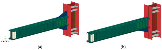
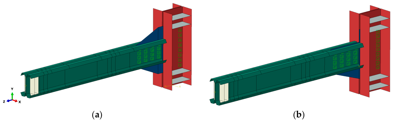
Finite element models of CFS bolted beam–column with through-plate connection have been simulated using FE Software ABAQUS [22] to study the failure deformation and the moment–rotation relationship. The model has been validated against previous experimental and numerical simulations [8,9,11,12,14,18,23]. In general, the numerical models of the connection included mainly FFB section and typical chamfered through plate (see Figure 1a) or a half-chamfered through plate (see Figure 1b).
Figure 1.
3D overview of the joint with: (a) typical chamfered through plate and (b) half-chamfered through plate.
Numerical model validation against experimental tests was carried out for three specimens A1, A2 and A3 [8]. In these tests, the beam cross-section consisted of a CFB section, while the through plate was a typical chamfered shape plate bolted to both back-to-back beam and column sections. These configurations are referred to as Type-A models. For the purpose of a comparative numerical study, a new set of models, designated as Type-F (F1, F2, and F3), was developed in this study. These models employ FFB section in combination with a standard chamfered through plate. The primary objective of this comparative analysis is to numerically evaluate and compare the performance of FFB connections against CFB connections. The FFB models were subsequently adopted as the baseline configuration for assessing additional connection arrangements in later stages of the study denoted with HC-G8. The general specifications of all models that have been developed in this study are illustrated in Table 1. Type-A and Type-F models both include 3 different arrangements of stiffeners considering partial and optimum stiffening solutions studied by Bagheri Sabbagh et al. [23] in addition to the basic solution where the beam is not stiffened. Both beam and column stiffeners were tied to the corresponding section.
Table 1.
General specifications of the numerical models.
The connection was numerically modelled to reproduce the experimental test conditions, with particular attention given to the geometry, material properties, and boundary conditions adopted in the reference study [8] in accordance with the modelling procedures recommended in recent numerical studies [9,11,12,14,18,23]. Both monotonic and cyclic loading protocols were considered in the analysis. The key modelling aspects of the developed ABAQUS models are explained in the following sections.
2.1. Geometry
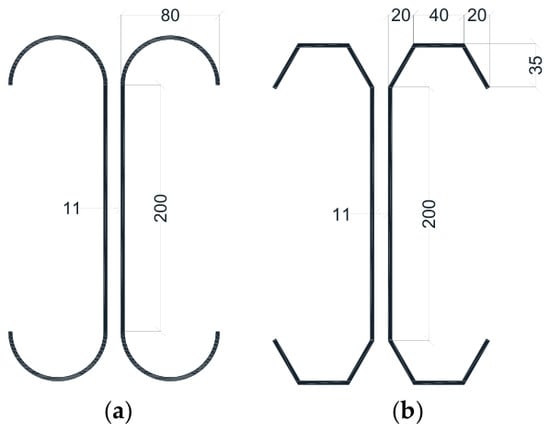
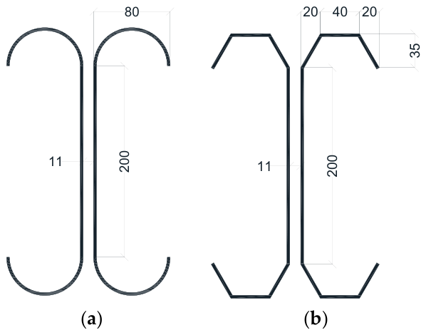
In Table 1, the general specifications adopted for the investigated numerical models are summarised. The cross-sectional dimensions of the beams considered in all models are presented in Figure 2. The geometry of the curved flange beam section, based on the configuration reported by Bagheri Sabbagh et al. [8] is illustrated in Figure 2a, whereas the dimensions of the folded flange section, adopted from previous studies [12,18], are shown in Figure 2b. The geometry of the typical chamfered T-shaped through plate, together with the corresponding bolt arrangement used in the connection, follows the configuration proposed by Bagheri Sabbagh et al. [8]. In addition, three different stiffener configurations, previously introduced by Bagheri Sabbagh et al. [9] were considered in the present investigation for benchmarking. The total length of the beam is 2.1 m and the distance from the free end of the beam to the edge of the through plate is 1.7 m. The column cross-section was taken as back-to-back flat flange channel section with depth of 300 mm, width of 150 mm, flange thickness of 16 mm and web thickness of 10 mm. The thickness of the column stiffeners is 10 mm.
Figure 2.
The geometry of the beam for (a) curved flange section and (b) folded flange section (present study). Dimensions in (mm).
2.2. Material Properties and Initial Geometrical Imperfections
Nonlinear elastic–plastic constitutive stress–strain model proposed by Haidarali et al. [24] has been used to simulate the material behaviour of the CFS beam and the through plate [14]. The results of coupon tests by Bagheri Sabbagh [25] were used to fit the adopted material model. The true stress–strain curves for the beam and through plate were derived from engineering stress–strain material model data and incorporated into ABAQUS [22]. The basic material properties for both the beam and through plate, including proof stress, ultimate strength, and the corresponding strain values, were adopted from the material properties obtained in reference Experimental Test A1 from the coupon tests. For Beam A, the 0.2% proof stress (σ0.2) was 313 MPa, the ultimate strength (σu) was 479 MPa, the corresponding 0.2% proof strain (ε0.2) was 0.00349, the elastic modulus (E) was 210,000 MPa, and E0 was 2100 MPa, whereas for Through Plate A, the corresponding values were 353 MPa, 516 MPa, 0.00368, 210,000 MPa, and 2100 MPa, respectively [14,25]. A linear kinematic hardening rule was adopted in the ABAQUS model to simulate the hardening behaviour of the material under cyclic loading using true stress–plastic strain data derived from the stress–strain curve of the material [14].
Initial geometric imperfections were also incorporated into the numerical model in accordance with the procedure proposed by Papargyriou et al. and Ye et al. [14,18], Geometrical imperfections were introduced by first performing a linear eigenvalue buckling analysis to identify the possible buckling modes of the connection. The dominant imperfection pattern was then selected based on the first relevant buckling mode. The initial geometry of the connection model was generated by introducing amplified initial deformation corresponding to the dominant buckling shape. Figure 3 presents the first dominant buckling mode obtained from the buckling analysis conducted on model F1.
Figure 3.
The dominant buckling mode for model F1.
Due to the use of lateral-bracing systems in the experimental test, global buckling will not be accounted for, thus the only governing buckling forms are local and distortional buckling. The dominant buckling mode for each FE model and the corresponding imperfection magnitude are reported in Table 2.
Table 2.
Dominant buckling modes for each numerical model.
Since the thickness of the beam is equal to 3 mm, the imperfection magnitude is considered to be 0.94t and 0.34t where t is the beam thickness for distortional and local imperfections, respectively, as suggested by Schafer et al. [26].
2.3. Bolt Modelling
The response of the bolts under both monotonic and cyclic loading was represented using point-based fasteners combined with simplified connector elements. This modelling approach provides sufficiently accurate results while requiring considerably less computational time and effort than more sophisticated modelling techniques [18]. The point-based fastener modelling technique requires the definition of the connected surface layers. For the beam bolt group, these layers comprise the beam web, through plate, and opposite beam web, whereas for the column bolt group they consist of the column web, through plate, and opposite column web. It should be noted that bolt slippage was not considered in the present numerical model. Accordingly, validation of the numerical results was carried out using Specimens A1, A2, and A3, for which no noticeable bolt slippage was observed during the experimental tests [14]. Introducing bolt slip into the behaviour of moment connections affects their cyclic response by producing a horizontal shift in the moment–rotation curves and enhancing energy dissipation, while having only a limited influence on the peak and ultimate moments [12].
2.4. Boundary and Loading Conditions
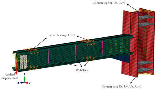
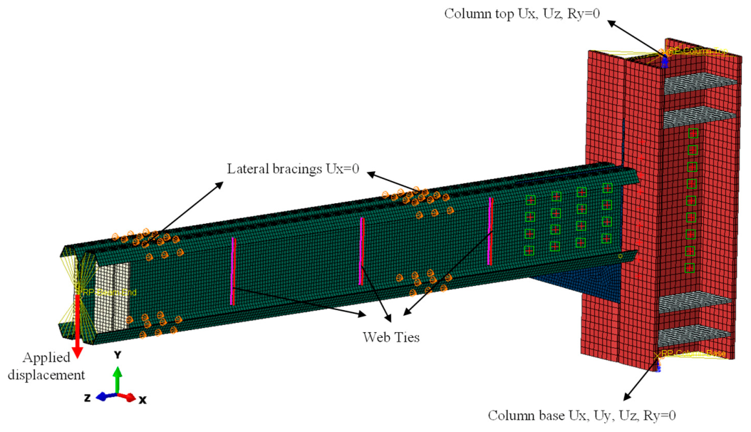
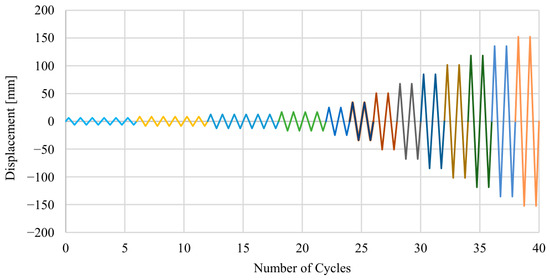
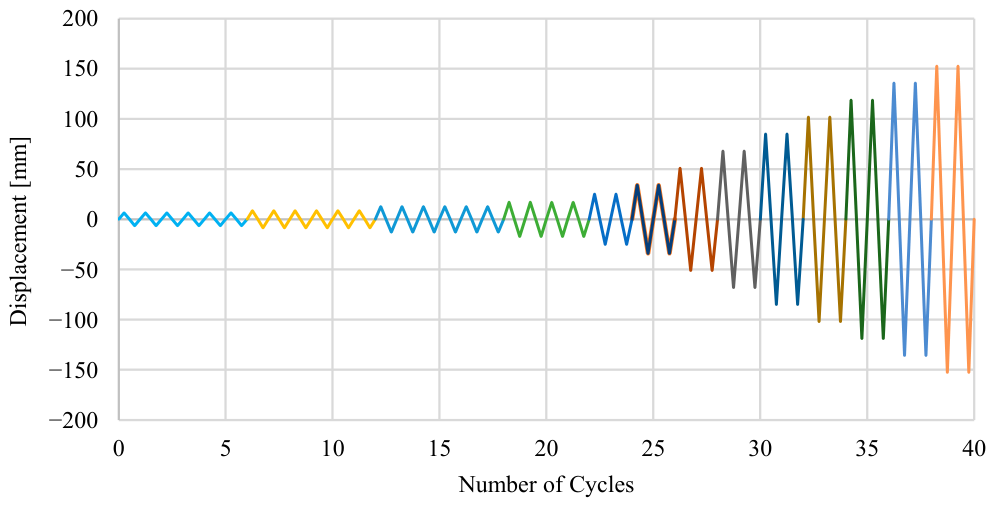
The boundary conditions illustrated in Figure 4 were defined to reproduce those adopted in the reference experimental programme [8] and in the subsequently validated finite element models [12,14,18]. Both monotonic and cyclic loading were applied through displacement control at the beam end, following the loading protocol in ANSI/AISC 341-22 code [27], and are shown in Figure 5.
Figure 4.
Loading and boundary conditions for HCG8 numerical model.
Figure 5.
Cyclic loading protocol according to ANSI/AISC 341-22 code [27].
2.5. Analysis and Elements Type
A general static analysis procedure was employed in the present study. The mesh size of 10 × 10 mm has been assigned for the beam and the through plate while the size of 20 × 20 mm has been adopted for the column. The element type that has been considered is S4R general-purpose finite element which is a 4-node, quadrilateral, stress/displacement shell element with reduced integration and a large-strain formulation. It has proven to accurately simulate the behaviour of thin-walled CFS members [14].
2.6. Validation
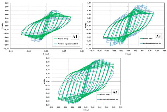
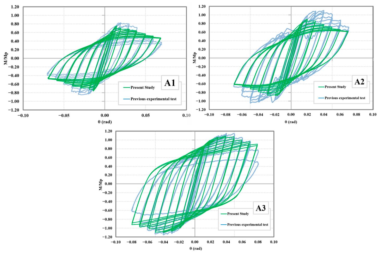
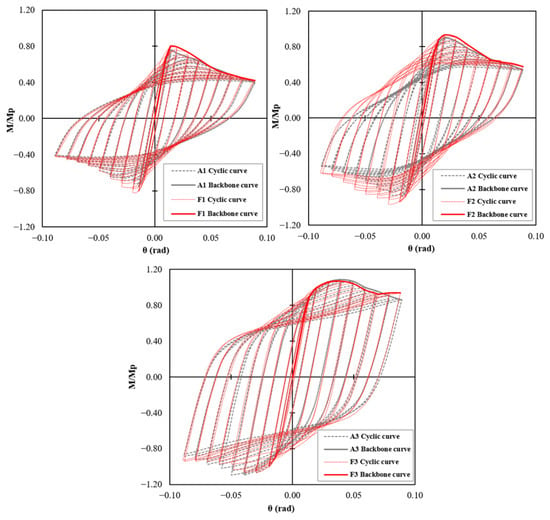
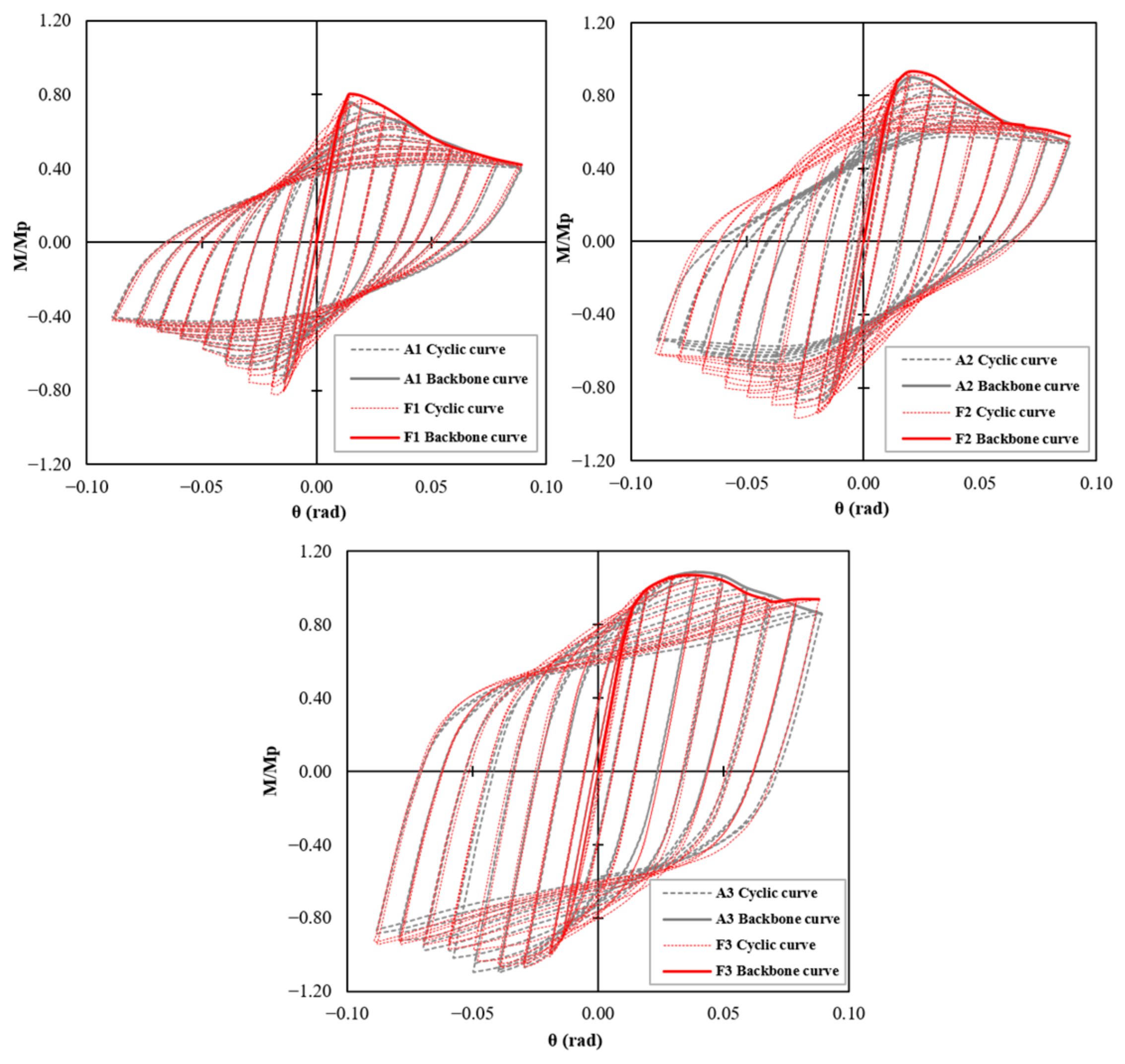
Numerical models of Type-A CFB sample have been built to simulate the experimental test performed on the specimens A1, A2 and A3 [8] and have also been reported in previous papers [11]. A comparison between the cyclic moment–rotation curves created by the FE model in the present study and those obtained experimentally by Bagheri Sabbagh et al. [8] is presented in Figure 6. The y-axis reports the ratio between the actual bending moment and MP of CFS beam, whereas the x-axis represents the rotation, calculated as the beam-end displacement divided by the distance from the beam end to the edge of the through plate.
Figure 6.
Model validation: M/Mp-θ curves of the experimental tests [8], with permission from Elsevier license number: 6344790821989, and present numerical test study.
The peak moment, rotational capacity, and initial rotational stiffness obtained from the FE analyses were compared with the corresponding experimental values, as summarised in Table 3. The percentage difference was calculated with respect to the experimental result. For peak moment, the FE models underpredicted the experimental values by 11.6%, 18.0%, and 5.5% for A1, A2, and A3, respectively. The rotational-capacity deviations were +12.5%, −16.7%, and +24.3%. The initial stiffness was overpredicted by 20.9%, 20.6%, and 26.4%, respectively. The largest discrepancy in peak strength occurs for specimen A2. the FE model predicts an approximately 18% lower peak moment capacity than that observed experimentally. Overall, the numerical model results show good agreement with previous experimental tests particularly for models A1 and A3 (see Figure 6). In contrast, for specimen A2, even though the failure shape obtained from FE model is very similar to the one reported in the reference experiment [8], there is a discrepancy in peak moment which was also reported in previous numerical studies [8,11] and is shown in Figure 6.
Table 3.
Quantitative comparison between experimental and numerical results.
3. Comparative Study: FFB vs. CFB
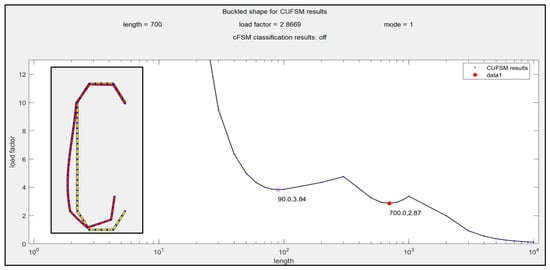
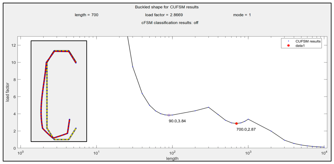
At the element level, analytical calculations were carried out to determine and obtain the maximum flexural capacity of both CFB and FFB. The analytical approach indicates that the nominal plastic moment of a beam can be expressed as the product of the yield strength of the steel and the plastic section modulus of the cross-section (ref. to Figure 2) evaluated considering the geometry (no buckling is considered). For the CFB section, the nominal plastic moment was found to be equal to 76 kN·m using a yield strength of Fy = 313 MPa, whereas for the FFB section the corresponding value was 74 kN·m. In both cases, the cross-sections were assumed to be fully effective with a uniform thickness of 3 mm. For FFB, this assumption is further validated by the signature curve analysis using CUFSM software as illustrated in Figure 7. In this figure, the horizontal axis represents the half-wavelength (length) of the buckling mode in millimetres (on a logarithmic scale), while the vertical axis denotes the corresponding load factor, which can be interpreted as the ratio between the critical buckling moment and yielding moment.
Figure 7.
The signature curve for FFB section with thickness of 3 mm.
The minimum point of the signature curve represents the governing critical buckling condition. In particular, the distortional buckling mode occurs at intermediate half-wavelengths (around 700 mm), where the load factor is approximately 2.87. This implies that the critical distortional buckling moment is about 2.87 times the yielding moment of the cross-section. This observation supports the assumption that distortional buckling does not control the design for the section under consideration and the section is fully effective, provided that global buckling is limited due to the introduction of lateral-bracing shown in Figure 5.
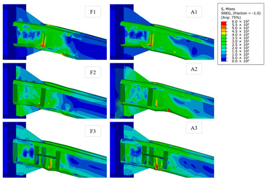
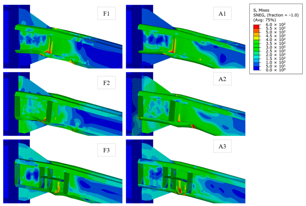
In the following, the FFB numerical model for cyclic analysis on the connection scale compares both the shape of failure modes and the obtained moment–rotation curves [21] but also analyses the global seismic performance of the connections. The failure modes obtained from the connection models subjected to cyclic loading are presented in in Figure 8 for configurations F1–F3 (left) and A1–A3 (right). It can be demonstrated that FFB connections behave similarly to CFB connections. The failures of models A1, A2, and F1, F2 occur in the beam web located at the edge of the through plate while for models A3, F3 buckling is delayed and occurs in the beam flanges outside the connection zone.
Figure 8.
Failure modes for A and F models represented by von Mises stress distributions (MPa).
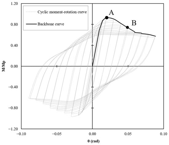
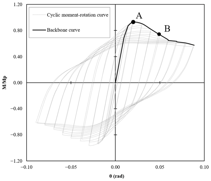
The moment–rotation curves obtained from FE models and presented in Figure 9 indicate a similar response between the connections incorporating FFB sections and those employing a CFBs. In particular, the FFB connection models exhibit initial stiffness and moment resistance values that are in close agreement with, and in some cases higher than, those predicted for the corresponding CFB connection models. This is reflected in Table 4, which summarises the moment–rotation values at the characteristic points identified from the cyclic response of each model. These points were determined from the envelope of the corresponding cyclic moment–rotation curve. Point A represents the maximum flexural capacity, whereas Point B defines the ultimate capacity at which the moment decreases to 80% of the maximum flexural capacity. The procedure used to identify these characteristic points is illustrated for Model F2 in Figure 10.
Figure 9.
Moment–rotation curves for FFB and CFB numerical models [21].
Table 4.
FFB and CFB connections performance.
Figure 10.
Cyclic curve characteristic points for model F2.
The Table 4 reports the models Type-A and Type-F with results in terms of MP, flexural capacity of the connection, normalised peak moment (Mmax/MP), normalised ultimate moment (Mu/MP), the rotation at yielding (θy) and the ultimate rotation (θu). As can be seen, both types of connections reach higher values of capacity with increasing number of stiffeners. In particular the A3 and F3 connection successfully reaches their plastic moment capacity. In contrast, models A1, A2, F1 and F2 fall short by approximately 15–30%. As reported in Bagheri Sabbagh et al. [8,9] this difference can be attributed to the improved strength of the connection that takes advantage from the presence of the stiffeners by postponing the initiation of local buckling. However, while this design enhances structural performance, it also introduces construction difficulties due to its added complexity.
The normalised peak capacities of models F1 and F2 exceeded those of the corresponding A1 and A2 models by approximately 8% and 3%, respectively, whereas the peak capacity of model F3 was approximately 2% lower than that recorded for model A3. Connection performance classification reported in Table 4 was based on the strength degradation drift angle criteria according to ANSI/AISC 341-22 [27]. A connection was classified as satisfying the requirements for a SMF when it was capable of accommodating a rotation of at least 0.04 rad while maintaining a flexural resistance of at least (0.80 Mp) at 0.04 rad. A connection that did not satisfy the SMF criteria but was capable of accommodating a rotation of at least 0.02 rad while maintaining at least (0.80 Mp) at 0.02 rad was classified as satisfying the requirements for an IMF. The values of (M0.02/Mp), and (M0.04/Mp) for each numerical model are presented in Table 4 to explicitly demonstrate compliance with the corresponding acceptance limits. The seismic performance of both types of sections has been evaluated based on ductility and energy dissipation capacity parameters. The ductility was computed as the ratio between the ultimate rotation and the rotation at yielding point of the backbone of cyclic moment–rotation curve. The ultimate rotation values were taken as the rotation that corresponds to 80% of the maximum peak connection moment. The energy dissipation capacity was considered as the area below the equivalent bilinear elastic–plastic curve constructed by the bilinearisation of the backbone curve [14]. The Table 4 reports the results of ductility and energy dissipation capacity. Models F1 and F2 exhibit approximately 5–12% lower ductility compared to models A1 and A2, whereas model F3 achieves about 2% higher ductility than model A3. In terms of energy dissipation, the differences between CFB and FFB models are minimal, with variations within ±4%. The seismic performance of the FFB connection closely matches that of CFB and the difference in the seismic parameters is not significant. However, further experimental investigations are needed to clarify the behaviour of the connection under seismic events.
4. Innovative Stiffener-Free Configurations for Beam–Column Using FFB
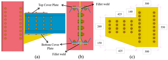
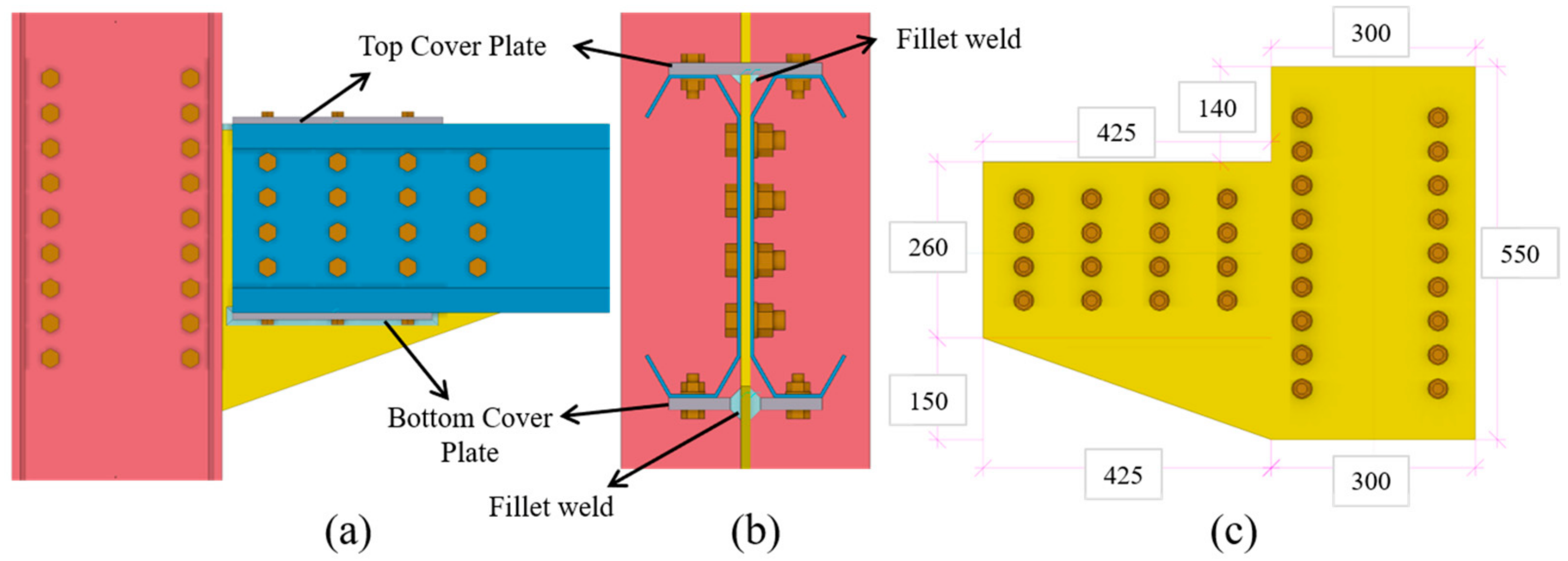
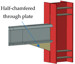
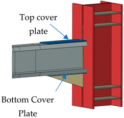
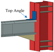
New configurations are designed and studied taking into account the practical employment of the connection in real world construction practices using FFB section. The proposed configurations, reported in Table 5, allow to have the space for floor system over the beam without physical restrictions due to chamfered through plate. With this aim, a half-chamfered solution is introduced together with additional components including top and/or bottom cover plates or top angle trying to avoid the use of the stiffeners that require welds. The Figure 11a presents an example of the connection configuration of HC-G8-TBCPL. The adopted geometry of the half-chamfered through plate is shown in Figure 11c. A thickness of 8 mm for the through plate, which is more than twice the thickness of the beam, is selected in the study to avoid failure [14]. Modifying the shape from chamfered through-plate to half-chamfered plate, retaining only the bottom portion, will help overcome the constraints associated with installing the floor system. Top and bottom cover plates are welded to the through plate with fillet welds that can be hidden within the gap due to the folded shape of the beam. The connection configuration provides space to accommodate the welded joints between the cover plates and the through plate, as illustrated in example HC-G8-TBCPL in Figure 11b. This arrangement not only meets performance requirements but also allows the welding to be carried out off-site, with final assembly completed on-site, thereby in proposed models, the through plate with cover plate will be a prefabricated member adding a good level of enhancement in production efficiency.
Table 5.
New practical solutions for CFSMR joints suitable for construction practices.
Figure 11.
HC-G8-TBCPL FFB practical connection: (a) side view (b) front view (c) half-chamfered through-plate geometry. Dimensions in (mm).
The model analysis will always refer to Model F1. The seismic behaviour and structural performance of these connections are tested under cyclic loading protocol. The results are discussed in terms of failure shapes and moment–rotation curve and also ductility and energy dissipation capacity are extracted.
4.1. Connection Configurations
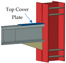
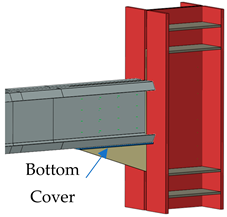
As mentioned, the reference model is F1 already described in Section 3. Five configurations are introduced including first the simple HC-G8 model which represents a folded flange beam-to-column connection using half-chamfered through plate of 8 mm thickness connection as shown in Table 5. Additionally, HC-G8-TCPL model configuration includes a top cover plate was bolted to the top flanges of the beam and welded to the upper edge of the half-chamfered through plate. Furthermore, with HC-G8-BCPL model, the half-chamfered through-plate solution is integrated by bottom cover plates bolted from each side to the bottom flange of the FFB section and side welded to the through plate (Figure 11b). This solution can increase the capacity of the connection with the possibility of reducing the number of bolts connecting the webs of the beam to the through plate providing more convenient solution. However, welding the cover plate will introduce some concerns related to the fast implementation of the connection compromising the fast erection and rapid assembly features of the CFS systems unless it is welded off-site. Adding to the previous models, HC-G8-TBCPL model is introduced addressing a mixed solution between the previous two models BCPL and TCPL. The aim of this model is increasing the capacity of the connection without introducing stiffeners in the connection zone, see Figure 11. Finally, HC-G8-TA model tests the connection with half-chamfered through plate and bolted top angle to increase the capacity of the connection by partially engaging the flange in transforming the moment to the column as studied in other works [14]. All HCG8 connections components specifications including the size of each component as well as the number and size of bolts are reported in Table 6. The material used for each connection component is similar to the material adopted for the through plate as reported in Section 2.2.
Table 6.
HCG8 connections components specifications.
4.2. Connection Performance
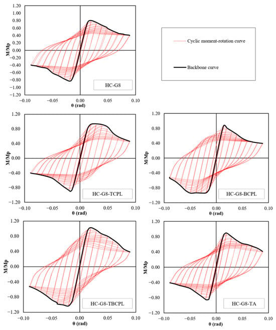
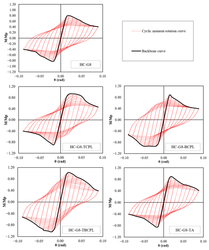
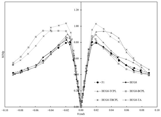
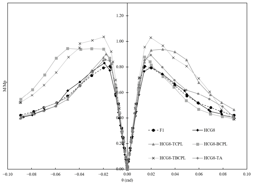
The cyclic flexural performance has been studied through cyclic moment–rotation responses (see Figure 12) of the numerical models reported in Table 5 and described in the previous paragraph. The arrangements of these models, in contrast with previous beam–column solutions (Type-A and Type-F), are not symmetric and therefore an extension of the traditional study approach considering energy dissipation and ductility had to be modified. Accordingly, since the first loading and unloading cycle, the structural response shows non symmetric diagrams. For this reason, backbone curves were extracted by connecting the points that define both the positive and negative rotations through the application of hogging and sagging bending moment respectively induced by the applied displacement (see Figure 5). Positive rotations branches correspond to the envelope of the upward loadings, where the top flanges of the beam are in compression and the bottom flanges are in tension, whereas the opposite condition occurs under negative rotations branches. To simplify the analysis and for comparison purposes, all backbone curves branches considering both positive and negative rotation are extracted and illustrated in Figure 13. The negative moments are presented in absolute terms for better representation and comparison with positive ones.
Figure 12.
Cyclic moment–rotation curves of HCG8 models.
Figure 13.
Backbone curves of HC-G8 models.
The maximum relative moment capacity was reached by Model HC-G8-TBCPL, where a mixed solution of both top and bottom cover plate was adopted. It has to be mentioned that even though this solution is the most complex one among the proposed configurations due to the introduction of welding, it can be classified as full-strength connection according to EN1993-1-8 [28] as the ratio M/Mp exceeds 1. It is worth mentioning this have been obtained without any introduction of stiffeners in the connection zone. The HC-G8-TCPL model with the top bolted cover plate reaches 94% of the FFB section moment capacity with a favourable ductile post-peak behaviour with positive rotations. Similarly, the model BCPL with the bottom cover plate was able to reach about 95% of the maximum flexural capacity in the negative rotations and 90% in the positive rotation part. With HC-G8-TA model, the achieved normalised capacity was about 90% in positive rotation where the top angle is under compression and 86% in negative rotation. Compared to F1 model, the elimination of the top chamfered part of the through plate would not affect the overall maximum flexural capacity as both F1 and HC-G8 models reach about 80% of the MP of the FFB. With respect to these two models, all the others achieved higher flexural capacities.
The connections are classified according to EN 1993-1-8 [29], in terms of rotational stiffness and joint relative moment resistance with respect to the beam. According to the criteria in EN 1993-1-8 provisions, all the proposed models can be classified as semi-rigid. From strength point of view, only HC-G8-TBCPL connection developed moment resistance higher than the beam resistance and thereby can be classified as full-strength joint. On the other hand, all the other models can be classified as partial-strength joints exhibiting at least 80% of the connected beam flexural resistance.
The initial stiffness of the HC-G8 model is slightly lower than that of the basic F1 model, whereas all other models reported in Table 7 exhibit similar or higher initial stiffnesses. The addition of the top and/or bottom cover plate or a bolted top angle will increase the moment capacity of the connection from 8% up to 29% with respect to the connection with the half-chamfered through plate HCG8 as well as the basic model F1. The seismic response of the connections was evaluated through ductility and energy dissipation parameters that were extracted according to Papargyriou et al. [14] and reported in Table 7.
Table 7.
Ductility and energy dissipation for HC-G8 and F1 models.
The ductility of the connection was estimated considering both positive and negative rotations. The ultimate rotation was taken as the rotation that corresponds to 20% reduction in connection moment capacity. The connection with the bottom cover plate HC-G8-BCPL achieved the highest ductility ratio in negative rotation state where the bottom flange of the beam is under compression. On the contrary, the behaviour of the HC-G8-TCPL was more ductile at the upper part of the connection where the top flange bolted to the cover plate is under compression. All connections models except for the HC-G8-BCPL and HC-G8-TCPL models can develop ductility ratios higher than 3 on both positive and negative states which is sufficient to develop full plastic hinge.
For what regards the energy dissipation capacity, the total global behaviour of both negative and positive loading cycles together was considered in the final estimation in order to compare the overall dissipation capacity given the asymmetric behaviour of both the HC-G8 connections and the basic one F1 (symmetric). The HC-G8 model with half-chamfered through plate dissipates more or less the same amount of energy as F1 model with typical chamfered through plate (see Table 7). The highest energy dissipation capacity was observed by the HC-G8-TBCPL achieving 56% higher capacity with respect to the basic model F1.
The classification of the connections based on the strength degradation drift angle criteria according to ANSI/AISC 341-22 [27] (see Table 7), was based on the lower performance class of both positive and negative rotations envelopes. Such criteria indicate that the strength degradation drift angle is set at 0.02 for IMF and 0.04 rad for SMF with having maintained at least 80% of plastic moment of the beam. While the results of this study are general and are expected to contribute to more efficient design of moment-resisting connections in CFS structural systems, further experimental investigations are required to validate the proposed connection configurations and to confirm their behaviour under realistic cyclic loading conditions. The experimental programme should also include element-level tests on FFB sections to evaluate their flexural behaviour and confirm their plastic moment capacity. These investigations are planned for future work and will be reported in subsequent publications.
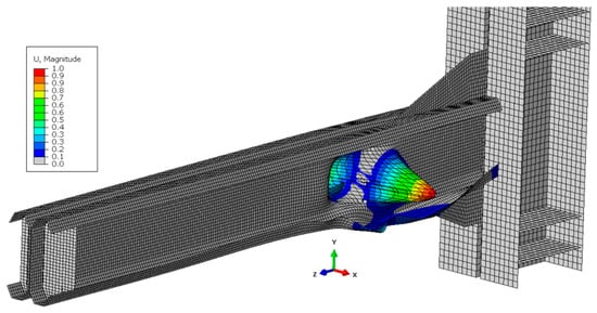
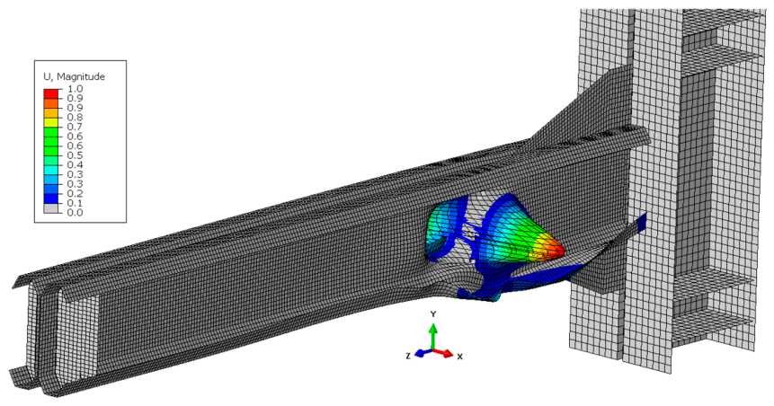
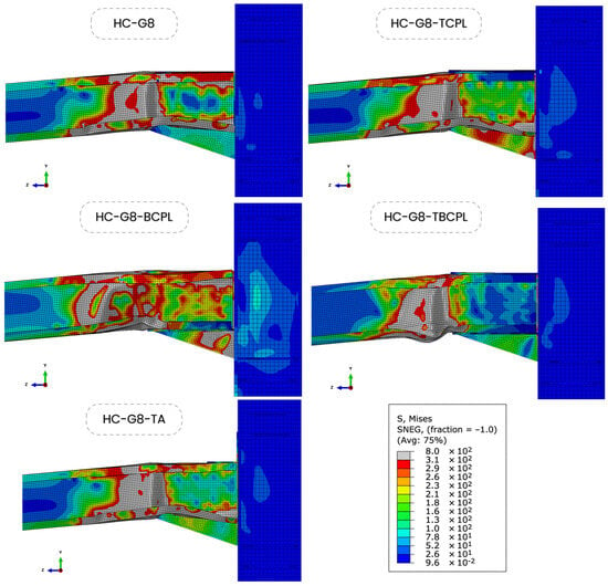
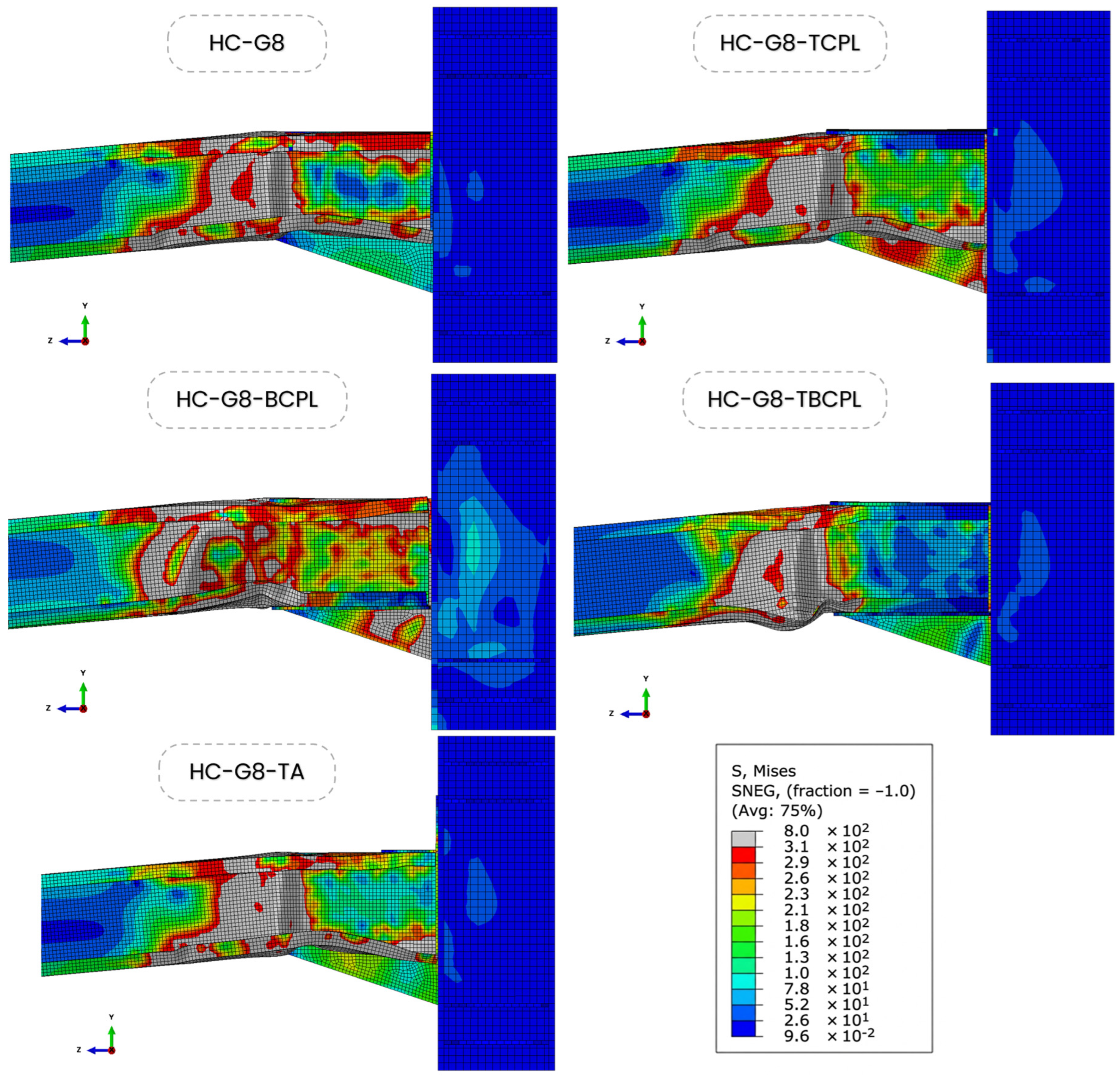
The failure patterns in Figure 14 show that the basic HC-G8 configuration is governed by local web buckling near the through-plate edge together with distortional buckling of the compression flange within the connection region. HC-G8-TCPL and HC-G8-TA exhibit similar mechanisms, as the restraint is concentrated mainly on the top flange. Under cyclic loading, the effectiveness of these components varies with load direction because the connected flange alternates between tension and compression, producing some directional variation in stiffness, yielding, and local deformation. In contrast, HC-G8-BCPL shifts both web local buckling and flange distortional buckling away from the connection region, although localised yielding develops in the through plate. The HC-G8-TBCPL configuration provides restraint to both flanges, delays local and distortional buckling, and relocates the governing deformation into the beam outside the joint while maintaining a comparatively stable stress distribution within the connection zone. Such relocation of inelasticity away from the joint is favourable for seismic applications. However, these HC-G8 configurations have not been experimentally validated directly; therefore, although the validated Type-A modelling assumptions were transferred consistently, the predicted behaviour should be interpreted comparatively until dedicated cyclic tests are available.
Figure 14.
Failure shapes of HC-G8 connection configurations.
5. Conclusions
This study conducted a numerical investigation into the cyclic performance of CFS bolted moment-resisting connections, focusing on the use of FFB sections as an alternative to CFB. FE models were developed, validated against existing experimental results, and used to explore new practical joint configurations, such as those with half-chamfered through plates and cover plates. The study examined their cyclic moment–rotation performance, ductility, and energy dissipation capacities. Based on the presented results, the following key conclusions can be drawn:
- The comparative study revealed that FFB connections exhibit seismic performance comparable to that of traditional CFB connections in terms of moment capacity, ductility, and energy dissipation.
- At the connection level, several practical FFB configurations were investigated. These included a half-chamfered through plate to create clearance for floor systems and the use of top and/or bottom cover plates to enhance connection strength. These solutions eliminate the need for welded stiffeners, reducing fabrication complexity and labour effort.
- Replacing the chamfered through plate with the half-chamfered solution with the introduction of top or/and bottom cover plate or a bolted top angle can improve the flexural capacity of the connection up to 29% without the need for welded stiffeners in the connection zone.
- All HC-G8 connection configurations satisfied the seismic performance requirements for classification as Intermediate Moment Frames (IMF) under lateral load-resisting systems. Among the tested numerical models, only the HC-G8-TBCPL configuration with both top and bottom cover plates demonstrated sufficient ductility and energy dissipation capacity to meet the criteria for Special Moment Frame (SMF) classification.
- The cyclic hysteretic responses of the proposed configurations were asymmetric due to the geometry and load path, necessitating a modified evaluation approach for moment–rotation performance. Among the examined configurations, the HC-G8-TBCPL joint, achieved the highest flexural capacity and was capable of transferring the full plastic moment of the FFB section satisfying the criteria for Special Moment Frame (SMF) classification.
- From a practical perspective, using FFB sections in addition to the half-chamfered through-plate concept, is expected to improve compatibility with floor-system installation, while the use of bolted cover plates or angles may reduce reliance on welded stiffeners and potentially simplify fabrication and erection. These practical advantages, however, are anticipated benefits and were not directly quantified in the present study.
- A principal limitation is that the newly proposed HC-G8 configurations have not yet been directly validated through dedicated experiments. The reported cyclic performance and seismic structural system classifications are therefore based on the adopted and previously validated numerical modelling framework. Experimental testing of the proposed configurations is required to confirm the predicted behaviour and to support future design recommendations and codification.
Author Contributions
Conceptualisation, W.A.S. and F.T.; methodology, W.A.S.; software, W.A.S. and S.M.M.; validation, W.A.S., F.T., S.M.M. and I.H.; formal analysis, W.A.S.; investigation, W.A.S.; resources, F.T.; data curation, W.A.S.; writing—original draft preparation, W.A.S.; writing—review and editing, F.T. and I.H.; visualisation, W.A.S. and F.T.; supervision, F.T., S.M.M., and I.H.; project administration, F.T. All authors have read and agreed to the published version of the manuscript.
Funding
This research received no external funding.
Data Availability Statement
The data presented in this study are available from the corresponding author upon reasonable request.
Conflicts of Interest
The authors declare no conflicts of interest.
Abbreviations
The following abbreviations are used in this manuscript:
| AISC | American Institute of Steel Construction |
| AISI | American Iron and Steel Institute |
| ANSI | American National Standards Institute |
| CFB | Curved Flange Beam |
| CFS | Cold-Formed Steel |
| CFSMR | Cold-Formed Steel Moment-Resisting |
| CFSMRF | Cold-Formed Steel Moment-Resisting Frame(s) |
| CUFSM | Constrained and Unconstrained Finite Strip Method |
| EN | European Standard |
| EU | European Union |
| FE | Finite Element |
| FFB | Folded Flange Beam |
| IMF | Intermediate Moment Frame |
| OMF | Ordinary Moment Frame |
| SMF | Special Moment Frame |
References
- Eea (European Environment Agency). Addressing the Environmental and Climate Footprint of Buildings; European Environment Agency: Copenhagen, Denmark, 2023. [Google Scholar] [CrossRef]
- Programme UNE. Architecture YC for E+. In Building Materials and the Climate: Constructing a New Future; United Nations Environment Programme: Nairobi, Kenya, 2023; Available online: https://digitallibrary.un.org/record/4020839?v=pdf (accessed on 25 September 2026).
- European Economic and Social Committee. Conclusions of the EESC Conference on the “Housing Crisis in Europe-the way forward?”. 2024. Available online: https://www.eesc.europa.eu/en/our-work/publications-other-work/publications/conclusions-eesc-conference-housing-crisis-europe-way-forward (accessed on 25 September 2026).
- European Commission. The European Green Deal—Delivering the EU’s 2030 Climate Targets; Publications Office of the European Union: Luxembourg, 2023. [Google Scholar]
- Johnston, R.P.D.; McGrath, T.; Nanukuttan, S.; Lim, J.B.; Soutsos, M.; Chiang, M.C.; Masood, R.; Rahman, M.A. Sustainability of Cold-formed Steel Portal Frames in Developing Countries in the Context of Life Cycle Assessment and Life Cycle Costs. Structures 2018, 13, 79–87. [Google Scholar] [CrossRef] [Scilit]
- Paul, B.; Roy, K.; Chen, X.; Shahmohammadi, A.; Hajirasouliha, I.; Lim, J.B. Simplified design method for cold-formed steel portal frames with back-to-back channel sections. J. Constr. Steel Res. 2026, 237, 110077. [Google Scholar] [CrossRef] [Scilit]
- Hasanali, M.; Roy, K.; Mojtabaei, S.M.; Hajirasouliha, I.; Clifton, G.C.; Lim, J.B. A critical review of cold-formed steel seismic resistant systems: Recent developments, challenges and future directions. Thin-Walled Struct. 2022, 180, 109953. [Google Scholar] [CrossRef] [Scilit]
- Sabbagh, A.B.; Petkovski, M.; Pilakoutas, K.; Mirghaderi, R. Experimental work on cold-formed steel elements for earthquake resilient moment frame buildings. Eng. Struct. 2012, 42, 371–386. [Google Scholar] [CrossRef] [Scilit]
- Sabbagh, A.B.; Petkovski, M.; Pilakoutas, K.; Mirghaderi, R. Development of cold-formed steel elements for earthquake resistant moment frame buildings. Thin-Walled Struct. 2012, 53, 99–108. [Google Scholar] [CrossRef] [Scilit]
- Ye, J.; Hajirasouliha, I.; Becque, J.; Pilakoutas, K. Development of more efficient cold-formed steel channel sections in bending. Thin-Walled Struct. 2016, 101, 1–13. [Google Scholar] [CrossRef] [Scilit]
- Sabbagh, A.B.; Petkovski, M.; Pilakoutas, K.; Mirghaderi, R. Cyclic behaviour of bolted cold-formed steel moment connections: FE modelling including slip. J. Constr. Steel Res. 2013, 80, 100–108. [Google Scholar] [CrossRef] [Scilit]
- Ye, J.; Mojtabaei, S.M.; Hajirasouliha, I. Seismic performance of cold-formed steel bolted moment connections with bolting friction-slip mechanism. J. Constr. Steel Res. 2019, 156, 122–136. [Google Scholar] [CrossRef] [Scilit]
- Seok, S.; Kim, T.S. Analytical model for cyclic behavior of cold-formed steel bolted connection frames considering local buckling. Thin-Walled Struct. 2025, 207, 112707. [Google Scholar] [CrossRef] [Scilit]
- Papargyriou, I.; Mojtabaei, S.M.; Hajirasouliha, I.; Becque, J.; Pilakoutas, K. Cold-formed steel beam-to-column bolted connections for seismic applications. Thin-Walled Struct. 2022, 172, 108876. [Google Scholar] [CrossRef] [Scilit]
- Maali, M.S.; Tavlaşoğlu, M.E.; Maali, M. Experimental study on the cold-formed steel beam-to-column screw connections for seismic application. Structures 2025, 72, 108173. [Google Scholar] [CrossRef] [Scilit]
- Paul, B.; McCrum, D.; Roy, K.; Wrzesien, A.; Hajirasouliha, I.; Lim, J.B. Moment capacity of back-to-back cold-formed steel channel bolted joints: An experimentally validated design approach. Eng. Struct. 2026, 367, 123664. [Google Scholar] [CrossRef] [Scilit]
- Mojtabaei, S.M.; Becque, J.; Hajirasouliha, I. Local Buckling in Cold-Formed Steel Moment-Resisting Bolted Connections: Behavior, Capacity, and Design. J. Struct. Eng. 2020, 146, 04020167. [Google Scholar] [CrossRef] [Scilit]
- Ye, J.; Mojtabaei, S.M.; Hajirasouliha, I.; Pilakoutas, K. Efficient design of cold-formed steel bolted-moment connections for earthquake resistant frames. Thin-Walled Struct. 2020, 150, 105926. [Google Scholar] [CrossRef] [Scilit]
- CEN. Eurocode 3: Design of Steel Structures—Part 1-1: General Rules and Rules for Buildings; British Standards Institution: London, UK, 2015. [Google Scholar]
- CEN. Eurocode 3: Design of Steel Structures—Part 1-3: General Rules—Supplementary Rules for Cold-formed Members and Sheeting; British Standards Institution: London, UK, 2006. [Google Scholar]
- Safarani, W.A.; Tondolo, F. Cold-Formed Steel Moment-Resisting Connection: Numerical Study; The Swedish Institute of Steel Construction: Stockholm, Sweden, 2024. [Google Scholar]
- Dassault Systèmes Simulia. Abaqus 6.14 CAE User Guide; Dassault Systèmes Simulia: Johnston, RI, USA, 2014. [Google Scholar]
- Sabbagh, A.B.; Petkovski, M.; Pilakoutas, K.; Mirghaderi, R. Ductile moment-resisting frames using cold-formed steel sections: An analytical investigation. J. Constr. Steel Res. 2011, 67, 634–646. [Google Scholar] [CrossRef] [Scilit]
- Haidarali, M.R.; Nethercot, D.A. Finite element modelling of cold-formed steel beams under local buckling or combined local/distortional buckling. Thin-Walled Struct. 2011, 49, 1554–1562. [Google Scholar] [CrossRef] [Scilit]
- Sabbagh, A.B. Cold-Formed Steel Elements for Earthquake Resistant Moment Frame Buildings. PhD Thesis, The University of Sheffield, Sheffield, UK, 2011. [Google Scholar]
- Schafer, B.W.; Peköz, T. Computational modeling of cold-formed steel: Characterizing geometric imperfections and residual stresses. J. Constr. Steel Res. 1998, 47, 193–210. [Google Scholar] [CrossRef] [Scilit]
- ANSI/AISC 341-22; Seismic Provisions for Structural Steel Buildings. American Institute of Steel Construction: Chicago, IL, USA, 2022.
- CEN. Eurocode 3: Design of Steel Structures-Part 1-8: Joints; European Committee for Standardization: Brussels, Belgium, 2024. [Google Scholar]
- BS EN 1993-1-8:2005; Eurocode 3: Design of Steel Structures—Part 1-8: Design of Joints. British Standards Institution: London, UK, 2005.

Disclaimer/Publisher’s Note: The statements, opinions and data contained in all publications are solely those of the individual author(s) and contributor(s) and not of MDPI and/or the editor(s). MDPI and/or the editor(s) disclaim responsibility for any injury to people or property resulting from any ideas, methods, instructions or products referred to in the content. |
© 2026 by the authors. Licensee MDPI, Basel, Switzerland. This article is an open access article distributed under the terms and conditions of the Creative Commons Attribution (CC BY) license.