


Abstract
The preventive conservation of ground-level archaeological sites requires not only protection from direct weathering but also effective control of the surrounding microclimate. Conventional archaeological coverings generally fail to provide adequate environmental stability while generating significant physical, visual, and environmental impacts. This study presents an integrated methodology for the design, optimization, and validation of a lightweight double-layer covering conceived as a sustainable environmental protection system rather than a passive protective shelter. The proposed workflow integrates parametric optimization of geometry and materiality, Life Cycle Assessment (LCA), environmental monitoring, Computational Fluid Dynamics (CFD) simulations, and experimental validation. The methodology was applied to the 1st c. CE Roman Tomb of the Two Families, located within the Carmona Archaeological Complex (Spain), where the environmental performance of the covering was evaluated through more than one year of in situ monitoring and numerical simulations. The results demonstrate that the proposed solution effectively moderates the site’s microclimate while significantly reducing environmental impacts and material consumption compared with conventional protective structures. The close agreement between monitored and simulated data validates the proposed design methodology and confirms the reliability of the environmental models. This research demonstrates that lightweight archaeological coverings can be conceived as a sustainable environmental protection infrastructure, providing a potentially transferable methodological framework for preventive conservation that integrates structural efficiency, environmental control and sustainability from the earliest stages of the design process.
1. Introduction
The long-term conservation of archaeological remains preserved in situ depends not only on protection from direct weathering but also on maintaining a stable microclimate capable of limiting the physical, chemical and biological processes responsible for deterioration. Once excavated, archaeological materials experience an abrupt disruption of the environmental equilibrium in which they remained preserved for centuries (excavation trauma), becoming immediately exposed to fluctuations in temperature, moisture, solar radiation and wind. This sudden environmental transition accelerates deterioration processes, making microclimate regulation a primary objective of preventive conservation. Accordingly, protective coverings should no longer be regarded merely as shelters but as environmental systems designed to regulate heat and moisture exchanges while complying with the principles of reversibility, minimum intervention and compatibility with the archaeological context [1,2], even establishing active hygrometric regulation through double-layer membrane systems for fragile remains like Roman mosaics [3].
Conventional archaeological shelters have only partially fulfilled these objectives. Although rigid protective structures effectively reduce direct exposure to precipitation and solar radiation, they frequently generate considerable visual, physical and environmental impacts while providing limited control over the microclimate surrounding archaeological remains. This is a conclusion based on the systematic analysis of 21 existing covers in the Iberian Peninsula that revealed significant failures in providing real climatic stability [4]. Recent research has demonstrated that long-term preventive conservation depends less on shielding remains from external conditions than on controlling the coupled heat and moisture exchanges governing deterioration. Consequently, design strategies incorporating thermal insulation, natural ventilation, drainage and waterproofing have proven more effective in stabilising archaeological microclimates than conventional enclosure-based approaches [5]. Conversely, inadequate control of solar radiation, airflow and moisture has repeatedly been identified as a major cause of poor environmental performance, highlighting the importance of integrating environmental simulation into the earliest design stages, and identifying that many open and semi-open typologies fail to prevent erosion and thermal shocks [4].
These findings have fundamentally redefined the design criteria for archaeological protective structures. Current approaches increasingly prioritise lightweight, reversible and adaptable systems capable of regulating the surrounding microclimate while minimising intervention on both the archaeological substrate and the landscape [6]. Besides ensuring structural safety, contemporary design must also address rapid assembly, reduced foundations, adaptability to future excavations, ease of maintenance and environmental sustainability [7]. Parametric optimisation and Life Cycle Assessment (LCA) have further reinforced this transition by enabling structural efficiency, environmental performance and environmental impacts to be evaluated simultaneously during the conceptual design stage, resulting in an innovative system that reduces steel consumption by 50–75% and global warming impact by 77% [8].
Among the available solutions, lightweight membrane structures have emerged as particularly suitable for archaeological conservation because of their low self-weight, reversibility, rapid installation and minimal disturbance to archaeological remains. However, unlike conventional roofs, their environmental behaviour is governed by the coupled interaction between solar radiation, natural ventilation, ground thermal inertia and the thermo-optical properties of the envelope. Owing to their low thermal inertia and relatively high solar transmittance, membrane systems respond rapidly to changing climatic conditions, making environmental performance dependent on the overall design of the enclosure rather than on the membrane material itself [3,9].
Current research therefore focuses on regulating, rather than isolating, the microclimate beneath archaeological coverings. Solar radiation, natural ventilation, ground thermal inertia and the thermo-optical properties of membrane materials are increasingly regarded as complementary passive mechanisms acting together within a single environmental system. Under this perspective, the covering behaves as a climate-responsive envelope that moderates energy exchanges instead of acting as a simple physical barrier.
Finite element analyses demonstrate that reducing heat transfer in double-layer membrane systems requires combining highly reflective external surfaces with carefully controlled ventilation within the intermediate air cavity, where radiative and convective exchanges dominate the thermal response of the enclosure [10,11]. Likewise, CFD (Computational Fluid Dynamics) simulations of complex membrane geometries reveal that the interaction between solar radiation, natural convection and roof geometry generates large-scale airflow patterns that strongly influence indoor conditions. These studies also identify ground thermal inertia as a key factor, since part of the transmitted solar energy is stored in the soil and later released as delayed sensible heat, affecting the thermal stability of the protected space [12].
Research on advanced membrane materials further highlights the importance of thermo-optical properties. Studies on ETFE systems show that membrane colour, thickness, photovoltaic integration and daylight transmittance significantly influence internal temperature distribution, emphasising the need for effective airflow management [13,14]. Combined CFD simulations, in situ monitoring and PMV-PPD analyses further demonstrate the influence of natural ventilation, buoyancy-driven stratification and local environmental conditions on airflow patterns and solar exposure [15,16].
Experimental research since the 1990s has confirmed the decisive role of ground thermal inertia in the environmental behaviour of lightweight membrane structures. Large-scale tests showed that thermal stratification beneath single-layer membranes could be reduced from approximately 5.0 °C to 1.0 °C through pressurised air cooling beneath the pavement [17,18]. Later studies demonstrated that solar energy stored in the ground during the day is gradually released at night, maintaining the pavement warmer than the indoor air. These findings support passive cooling strategies, including evaporative pavement cooling, to reduce delayed heat release and improve microclimatic stability beneath lightweight coverings [19,20].
Building upon these advances, recent research has shifted from improving individual materials towards developing multilayer environmental envelopes that exploit passive physical processes to regulate the microclimate beneath lightweight structures. Because single-layer membranes transmit external thermal fluctuations with minimal delay [10], improving environmental performance depends not only on increasing thermal resistance but also on controlling radiation, airflow and heat storage. Passive environmental regulation has therefore become a central objective in the design of archaeological protective systems.
Several complementary strategies have been proposed. Evaporative cooling through photocatalytic water spraying reduces membrane temperatures under high solar radiation [21], while Phase Change Materials (PCM) decrease cooling demand by 18–25% in temperate climates when combined with effective natural ventilation [22,23]. Silica aerogel nanofibre blankets further improve thermal resistance, reducing thermal conductivity by up to 23% without significantly increasing weight [24]. Together, these developments show that material innovation is most effective when integrated within a broader environmental strategy.
The greatest advances have been achieved through multilayer membrane systems incorporating ventilated air cavities. Experimental and numerical studies demonstrate that combining an external solar-control membrane with a naturally ventilated cavity and an inner translucent or insulated layer significantly reduces radiative heat transfer while improving thermal stability [25]. The addition of aerogel or mineral wool within PTFE membrane assemblies lowers indoor temperatures by 4.8–7.7 °C under summer conditions [26,27]. CFD analyses further show that controlled airflow within the cavity limits overheating, condensation and humidity, while pneumatic ETFE systems reduce winter heating demand by 11–18%. Integrating photovoltaic modules within ventilated ETFE cushions also increases electrical efficiency by up to 25%, highlighting the potential of lightweight envelopes to combine passive environmental regulation with renewable energy generation [28,29,30,31,32].
Recent advances in ultralight and flexible photovoltaic technologies expand the possibilities for integrating renewable energy generation into lightweight architectural envelopes, reducing the additional weight and facilitating their adaptation to complex geometries [33]. Although the integration of photovoltaic systems into tensile membranes requires consideration of the compatibility between the deformations of both components [34], this constraint can be reduced by installing flexible photovoltaic modules after the membranes have been tensioned, also allowing for their selective placement in areas receiving higher solar radiation. Thus, for a photovoltaic collection area of 1.54 m2 and a total annual solar irradiation of 2266.64 kWh/m2 obtained from PVGIS [35], considering an efficiency of 18.81% and a performance ratio of 0.71, the potential electricity generation would be approximately 466.18 kWh/year. This order of magnitude demonstrates the potential feasibility of such solutions for meeting the limited energy demands associated with environmental control and monitoring systems.
As membrane systems become more sophisticated, their design requires the simultaneous optimisation of geometry, structure, materials, airflow, daylight and energy performance. Parametric design platforms integrate geometric modelling with finite element analysis and optimisation algorithms, enabling structurally efficient solutions from the earliest design stages [8,9,10,11,12,13,14,15,16,17,18,19,20,21,22,23,24,25,26,27,28,29,30,31,32,36]. Similar computational approaches have also been applied to timber gridshells, optimising both structural behaviour and modular fabrication for long-span lightweight roofs [37]. Parametric Behaviour Maps (PBM) further strengthen this workflow by linking climatic conditions with multiple design alternatives while minimising computational effort [38].
Despite these advances, BIM-based design still suffers from the limited availability of reliable analytical data for advanced membrane materials. To address this limitation, Sotubo [39] proposed the Analytical Properties Framework (APF), enabling the calibration and validation of innovative materials, including aerogel textiles, graphene composites and PCM-enhanced membranes, for building performance simulations. Using this framework, double-layer envelopes with ventilated cavities of 1.10–1.50 m achieved cooling energy savings of up to 56% under warm climatic conditions.
Environmental optimisation should also address the impact of the protective system itself. Gómez de Cózar et al. [40] integrated Life Cycle Assessment (LCA) with generative algorithms in BIM environments, allowing structural efficiency and Global Warming Potential (GWP) to be evaluated simultaneously during conceptual design. By linking material reduction directly to environmental performance through multi-objective optimisation, sustainability becomes an active design criterion rather than a post-design assessment, demonstrating that multi-objective optimization can lead to a 67% to 77% reduction in GWP compared to traditional coverings [8].
Despite the advances highlighted in lightweight structures, computational simulation, advanced materials and sustainable design, these developments have largely evolved as independent research fields. Consequently, archaeological site coverings continue to be evaluated either as structural systems or as environmental envelopes, with limited integration between passive climatic regulation, reversibility, computational optimisation and sustainability. A comprehensive design framework that combines these aspects for in situ archaeological conservation remains largely unexplored.
A comparative summary of the main protection approaches discussed above, including their principal advantages, limitations, environmental-control characteristics and reversibility, is provided in Supplementary Material S1, Table S1.
In light of these considerations, the principal contribution of this research is not the design of a lightweight archaeological covering, but rather the development and long-term validation of an original methodology that transforms archaeological coverings into a sustainable environmental system capable of improving the microclimatic conditions required for preventive conservation through the combined action of passive environmental strategies and controlled mechanical ventilation. To this end, a sustainable environmental protection system is proposed based on:
- Lightweight structure.
- Double-layer membrane covering generating an air cavity.
- Controlled ventilation.
- Monitoring.
- Numerical simulation.
- Energy self-sufficiency.
- Minimal environmental impact.
2. Research Objectives
As discussed above, the proposed approach redefines the protective covering from a passive shelter into a self-sufficient sustainable environmental system that improves the archaeological site’s microclimatic conditions through passive strategies complemented by controlled mechanical ventilation, while requiring only minimal energy consumption.
Building upon the advances achieved in this line of research [8], this study establishes the following primary objective: to develop an original sustainable environmental protection system based on lightweight double-layer coverings capable of effectively controlling the environmental variables that influence the physical deterioration of ground-level archaeological sites through self-sufficient, near-zero-energy monitored systems, while ensuring a high level of sustainability throughout the entire process.
To support the achievement of this primary objective, the following instrumental specific objectives are proposed:
- To develop parametric design tools for lightweight coverings that integrate the entire workflow, including design, simulation, optimization, and off-site fabrication using Computer Numerical Control (CNC) technology.
- To develop mathematical models for thermal and airflow simulation of lightweight double-layer coverings using Computational Fluid Dynamics (CFD).
- To design low-energy environmental conditioning strategies combining passive mechanisms with controlled mechanical ventilation for improving the environmental conditions within the protected space through continuous monitoring and controlled airflow management, and to evaluate their effectiveness in maintaining stable psychrometric conditions for the preventive conservation of the archaeological site.
- To develop prototype monitoring systems based on Open-Source software for the calibration of the mathematical simulation models.
- To develop methodologies for assessing the environmental impact of the overall process, including the design, fabrication, installation, operation, and reuse of the proposed covering systems, using the Life Cycle Assessment (LCA) approach.
- To apply the proposed methodology to a representative case study involving a ground-level archaeological site within an archaeological complex located in a Mediterranean climate, with the aim of evaluating its effectiveness and potential for transferability.
3. Materials and Methods
Based on the background presented above and the research objectives defined herein, the following methodology is proposed:
3.1. Model Generation
The success of the proposed system relies on the effective integration of the structural form with its appropriate adaptation to the heritage context and the site-specific climatic conditions governing the archaeological remains. Following the survey and geometric documentation of the archaeological assets under study, the initial geometry of the covering is generated using original parametric software developed in Grasshopper 3D® [version 1] (Robert McNeel & Associates, Seattle, WA, USA), employing the Kangaroo Physics® engine [version 2] (Daniel Piker) for membrane form-finding, both integrated within Rhinoceros® (Robert McNeel & Associates, Seattle, WA, USA). The design process also incorporates the selection of a reversible and recoverable foundation system according to the characteristics of the archaeological site:
- Perimeter steel sheet panels, adapted to the outline of the covering, which distribute structural loads over the ground while supporting granular fill ballast box. In addition to providing stability, the granular fill facilitates rainwater drainage. This foundation system is particularly suitable for open archaeological sites requiring fully enclosed coverings closely fitted to the terrain, without visually intrusive support.
- Surface ballast boxes, compatible with supported covering systems where the exceptional hardness of the ground prevents even shallow excavation.
- Steel ballast boxes filled with excavated soil, particularly suitable for medium- and long-span coverings with supports where shallow excavation is feasible.
Before proceeding with the structural design, it is necessary to verify that the covering provides adequate protection against both rainfall and solar radiation. To this end, original environmental simulation tools based on Ladybug Tools® (Ladybug Tools, USA) for Grasshopper, integrated within Rhinoceros, were developed.
3.2. Calculation and Sizing of All Structural and Foundation Elements
Based on the initial geometry correctly positioned on the site, the material specifications, cross-sections of all structural and foundation components, connection details and support conditions are defined.
According to the geometry and geographical location of the covering, wind and snow loads are determined and combined with the self-weight of all structural components to perform the structural analysis, elements sizing, and deformation assessment.
Following the structural design process, the total weight of the covering is calculated and verified against the target values established for this type of system in previous research papers [8].
Structural calculations are performed using Karamba3D® [version 3.1] (Clemens Preisinger, Vienna, Austria) integrated within Grasshopper, allowing the geometry to be automatically modified through the parametric model whenever the structural performance does not satisfy the established design criteria.
3.3. Design of Environmental Control Systems, Monitoring Installation and Energy Collection Systems
Based on previous research addressing the hygrothermal behaviour of lightweight double-layer structures through the manipulation of natural and forced airflow between the outdoor environment, the air cavity and the protected interior space [25,26,27], specific environmental control strategies are designed according to the physical and climatic boundary conditions of the case study. Four in-line ventilation units are integrated within the cavity of the prototype covering and connected through flexible aluminium ducts.
The passive environmental strategies, together with the controlled mechanical ventilation system, are subjected to continuous monitoring to evaluate the evolution of both indoor and outdoor psychrometric and environmental variables, including solar radiation, wind action, air temperature, relative humidity, CO2 concentration and air velocity, among others. These parameters govern the deterioration processes affecting the archaeological remains. The monitored data enable real-time, remote active control of airflow exchange strategies which can be activated, validated, and reconfigured through actuators compatible with LAN-based communication networks.
The proposed system has been conceived as a Nearly Zero-Energy Building (NZEB), incorporating integrated energy generation and storage systems within the covering itself. Consequently, the covering functions as an active energy-producing element capable of supplying the electricity required for both the air exchange equipment and the monitoring and control systems.
3.4. Design-Time Sustainability Evaluation of the Process Using LCA Tools
Once the geometry, material specifications, and required technical systems have been defined, the environmental impact of the proposed covering is evaluated using the Life Cycle Assessment (LCA) methodology. The assessment follows the methodology established in UNE-EN ISO 14040 [41] and comprises the following stages:
- Scope and objectives definition.The environmental impact is quantified in terms of Global Warming Potential (GWP), expressed as kg CO2 eq, based on the information generated by the parametric model. In accordance with UNE-EN 15978 [42], the following life cycle stages are considered: A1–A3, A4–A5 and C1–C4.The embodied environmental impacts associated with the photovoltaic panels, batteries, ventilation units, monitoring equipment, and all other technical components are included within the system boundary.At the design stage, phases B1–B5 are excluded from the scope of the present assessment in order to maintain methodological consistency and comparability with the previous study developed within this research line [8], in which these stages were also excluded. This exclusion represents a limitation of the present design-stage LCA and should not be interpreted as implying that maintenance and component replacement are irrelevant from a life-cycle perspective.Phase B6 (operational energy use) is excluded from the present assessment because the electricity required by the ventilation, monitoring, and control equipment is supplied by the integrated off-grid photovoltaic generation and battery storage system, with no electricity supplied by the external grid during operation. This exclusion should not be interpreted as implying that operational energy is intrinsically irrelevant from a life-cycle perspective. The embodied environmental impacts associated with the photovoltaic generation and battery storage systems are included within the product stage (A1–A3). The functional unit is defined as one square metre of archaeological site area covered in plan.
- Life cycle inventory.A complete inventory of construction products is generated automatically from the developed software.Average transport distances are assumed for theoretical analyses (A4 and C2), whereas actual transport distances are adopted for the specific case studies.Unit environmental impact values for stages A1–A3, A4, C2, C3, and C4 are obtained from the Ecoinvent 2.0 database [43].The impacts associated with stages A5 and C1 are assessed according to the methodology proposed by Kellenberger [44].
- Life cycle impact assessment.The environmental impacts associated with each life cycle stage are calculated automatically.Results are presented graphically, either disaggregated by individual stages or as an overall summary, facilitating their interpretation.
- Interpretation of results.Once the consistency of the results has been verified, the life cycle stages contributing the greatest environmental impacts are identified, enabling informed design decisions to reduce the overall environmental burden.A major advantage of the proposed methodology is its integration with the parametric model, allowing any design modification to automatically generate updated LCA results in real time.
3.5. Manufacturing and Assembly
Once the suitability of the proposed covering in terms of site integration, geometry, material specifications, technical systems, and environmental performance (GWP), assessed through Life Cycle Assessment, has been verified, the construction documentation required for fabrication is generated. The manufacturing strategy prioritises off-site industrial production of all components, including the foundation system, structural frame, and covering, using computer numerical control (CNC) technologies.
To this end, a Building Information Modelling (BIM) model is developed in Autodesk Revit® [version 21] (Autodesk, Inc., San Francisco, CA, USA) from the initial Rhinoceros model. The BIM model is then used to automatically generate construction drawings, which can subsequently be exported in CAD (AutoCAD® [version 23] (Autodesk, Inc., San Francisco, CA, USA)) format.
3.6. Prototype Monitoring: Definition and Rationale of the Operating Protocols for Different Climatic Seasons
The prototype was monitored over a 12-month period under six representative climatic scenarios corresponding to the study area’s climatic conditions [10]. The selected scenarios represent characteristic environmental operating conditions within the Mediterranean climatic context:
- Scenario 1: Warm, dry transitional season (T_out = 26.0–35.0 °C; RH_in < 70%).
- Scenario 2: Warm, humid transitional season (T_out = 26.0–35.0 °C; RH_in > 70%).
- Scenario 3: Summer period (T_out > 35.0 °C; RH_in < 70%).
- Scenario 4: Mild transitional season with precipitation (18.0 °C ≤ T_out ≤ 25 °C; RH_in > 70%).
- Scenario 5: Dry winter period (T_out < 17.0 °C; RH_in < 70%).
- Scenario 6: Humid winter period (T_out < 17.0 °C; RH_in > 70%).
For each of the climatic scenarios described, low-, medium-, and high-intensity operating protocols, applied over different durations, will be tested in order to identify those that are most effective at maintaining the environmental conditions within the enclosed archaeological space within ranges compatible with conservation.
Since the current CFD formulation does not include a moisture transport equation, the capability of the proposed system to modify relative humidity conditions within the protected archaeological space is assessed exclusively from the experimental monitoring data. Relative humidity is therefore treated as an experimentally monitored conservation variable and not as an output of the validated CFD model. The development of a fully coupled heat and moisture transfer model is identified as a relevant direction for future research.
3.7. Energy Simulation of Models. Development of Computational Calculation Tools
Once the most effective operating protocols have been identified for each climatic scenario, original computational software was developed to simulate the environmental conditions (the air temperature within both the conditioned archaeological space and the air cavity). The software was used to reproduce the selected operating protocols and to assess their agreement with the monitored data.
Following model calibration, the predictive capability of the computational tool was validated for the monitored archaeological site, enabling its application to obtain additional information on this case study and providing a basis for its future adaptation, calibration, and validation in other archaeological contexts.
This computational tool has been developed using the open-source software FreeFem (Frédéric Hecht, Sorbonne University, Paris, France), which is specifically designed to solve 2D and 3D partial differential equations (PDEs) using the finite element method (FEM). The computational mesh, consisting of triangular elements representing the different energy exchange domains (the air cavity and the protected archaeological space), is generated using Gmsh [version 4.11.1] (Christophe Geuzaine and Jean-François Remacle, University of Liège, Liège, Belgium) [45].
3.8. Assessment of Thermal Uniformity Within the Archaeological Strata
Once the predictive capability of the original simulation software has been validated, it is used during the design stage to estimate the thermal behaviour of the different archaeological strata after installation of the proposed protective covering. This assessment evaluates the ability of both the covering and its environmental conditioning system to maintain uniform temperature distributions throughout the archaeological layers, a key requirement for their long-term preventive conservation [6].
Figure 1 presents a schematic overview of the proposed methodology from an instrumental perspective, including the computational tools employed throughout the workflow.
Figure 1.
Flow diagram illustrating the different stages of the original methodology proposed in this study.
The case study presented in the following sections illustrates the complete implementation of the eight methodological stages, demonstrating their applicability and feasibility in a real archaeological context, while assessing the potential transferability of the proposed methodology to other ground-level archaeological sites.
4. Case Study: The Tomb of the Two Families (Carmona Archaeological Complex, Spain)
4.1. Description of the Archaeological Site
The Carmona Archaeological Complex (CAC) comprises a Roman cremation necropolis of outstanding importance for the study of funerary practices in Roman Hispania during the 1st and 2nd centuries CE [6]. It possesses considerable heritage value [46], both tangible and intangible, associated not only with the archaeological remains themselves but also with the history of their excavation, musealisation, and enhancement since their discovery. Consequently, the site represents a historiographical record of the evolution and application of conservation theory to this type of cultural heritage (Figure 2).
Figure 2.
Location of the Roman Tomb of the Two Families within the Carmona Roman Amphitheatre and Archaeological Site (Seville, Spain).
The complex contains both monumental tombs, consisting of burial chambers accessed through a courtyard or entrance space, and hypogeal structures comprising an access shaft leading to a chamber with niches for funerary urns containing cremated human remains. The case study presented here, Tomb of the Two Families, belongs to the latter typology and corresponds to a collective family mausoleum (Figure 3).
Figure 3.
Photograph of the archaeological site, Roman Tomb of the Two Families.
However, the integrity of these burials has been compromised by their geomorphological setting and by the vulnerability resulting from their exposure following excavation, particularly in structures that have lost their original protective covering [47]. The calcarenite bedrock is highly porous, promoting condensation, capillary moisture uptake and salt crystallisation. In combination with fluctuations in relative humidity, elevated CO2 concentrations and solar radiation, these processes have led to severe deterioration, including the loss of wall paintings, salt efflorescence and biological colonisation.
To mitigate these deterioration mechanisms, the implementation of a sustainable environmental system is proposed: a lightweight covering system designed to improve the environmental conditions affecting the archaeological remains through the combined action of passive environmental strategies and controlled mechanical ventilation. The objective is to stabilise the internal microclimate while maintaining equilibrium with the surrounding environment, thereby ensuring effective protection with minimal physical and visual impact on the site.
4.2. Model Generation
Using the point cloud survey obtained from the Information System of the Carmona Archaeological Complex (SICAC), an original parametric design tool was employed to generate a lightweight covering with an irregular trapezoidal plan (maximum dimensions: 4.85 m × 6.64 m). The geometry was defined according to criteria of architectural integration, heritage interpretation and adaptation to the site’s topographical constraints (Figure 4). The resulting design presents a smooth, low-profile geometry with minimal landscape impact, preserving the perception of the monument as a hypogeal burial structure.
Figure 4.
Plan view and cross-sections of the proposed covering design prior to structural and environmental verification.
The covering has an external height of 1.60 m above the existing ground level and a structural rise equal to 1/4 of its maximum plan dimension. The structural system consists of a mesh of six parabolic steel tubular arches supporting a double-layer textile covering, which forms an air cavity with a variable thickness ranging from 0.35 m at the perimeter base to 0.50 m at the crown.
To ensure structural stability without disturbing the archaeological substrate, no anchors or excavations were employed. Instead, the structure is supported by a continuous perimeter channel formed from folded galvanised steel sheet placed directly on the ground and ballasted with a 10.00 cm layer of gravel. This system simultaneously provides drainage and resistance against wind-induced uplift.
At the lowest point of the site, adjacent to the access path, the structure incorporates a vertical framework supporting a transparent textile oculus integrated within the double-layer membrane, allowing for visual inspection of the interior while providing access for researchers and maintenance personnel (Figure 5).
Figure 5.
Components of the proposed lightweight double-layer covering system.
Finally, the suitability of the proposed geometry was verified through annual solar radiation analyses using open-source computational tools (Grasshopper and Ladybug Tools integrated within the Rhinoceros 3D modelling environment) (Figure 6). The resulting solar radiation data were subsequently incorporated into Computational Fluid Dynamics (CFD) models. The simulations confirmed the effectiveness of the enclosed covering in protecting the archaeological remains while identifying the rear section of the structure as the area receiving the highest annual solar radiation, making it the optimal location for photovoltaic panels.
Figure 6.
Annual incident solar radiation analysis model.
4.3. Calculation and Sizing of Structural and Foundation Elements
The structural analysis was carried out within the elastic domain using the parametric structural analysis software Karamba3D [version 3.1] integrated into Grasshopper, without considering moment redistribution resulting from plastic hinge formation at the ends of the elements.
The structural design complies with UNE-EN 13782:2016, Temporary Structures. Tents. Safety [48].
Permanent actions, as defined in Clause 7 of the Standard, include the self-weight of the structure, the textile covering and any technical equipment or auxiliary devices supported by or suspended from the structure. No imposed loads due to occupancy were considered. Owing to the lightweight and flexible nature of the proposed structure, seismic actions, thermal effects, support settlements, impact loads and dynamic actions were neglected.
Variable actions include a snow load of 0.20 kN/m2, in accordance with CTE DB SE-AE, and a reduced peak velocity pressure of qp(ze) = 0.30 kN/m2 applied according to the geometric limits established in EN 13782:2016 (Clause 7.4.2.2) for structures up to 10.00 m in width and 5.00 m in height. Wind pressure coefficients were adopted from CTE DB SE-AE owing to the variable-curvature geometry of the covering.
All structural connections were designed, analysed, and constructed as rigid joints, except for the arch-to-perimeter ring connections, which were modelled as pinned supports for structural analysis purposes (Figure 7). The specified materials comprise an S275 J0 steel tubular structural frame (40.3 mm section), 1.50 mm-thick S280 GD galvanised steel sheet with a zinc coating of 275 g/m2, and Z8.8 high-strength steel bolts.
Figure 7.
Structural analysis model used for numerical simulations.
The interface with the ground consists of galvanised steel sheets stabilised by gravel ballast and natural soil (average unit weight: 18.00 kN/m3), providing adequate resistance against sliding and overturning. Bearing failure was not considered critical owing to the exceptionally low weight of the structure.
The structural analysis results (Figure 8) confirm that the structure satisfies all Ultimate Limit State requirements, with a maximum utilisation ratio of 45% located at the upper region of the front parapet, where the highest stresses occur.
Figure 8.
Distribution of maximum stresses in the structural elements.
Regarding the Serviceability Limit States, both the maximum vertical deflection and the horizontal displacement remain below the limit of L/300 prescribed by CTE DB SE (Clause 4.3.3.1) for all analysed load combinations (Figure 9).
Figure 9.
Structural deformation under wind loading for the four wind load hypotheses considered: XX+, XX−, YY+, and YY−.
Compared with other archaeological covering systems developed in Spain [8], the proposed design exhibits high material efficiency, an exceptionally low self-weight (19.52 kg/m2), rapid transport and assembly, minimal physical impact on the archaeological site and a maximum envelope-to-plan area ratio of 1.20.
4.4. Design of Environmental Control Systems, Monitoring Installation and Energy Collection Systems
To verify, at the design stage, the performance of the proposed covering as a sustainable environmental protection system for the archaeological site, an environmental control system combining passive environmental strategies with controlled mechanical ventilation was implemented. The system comprises 4 in-line ventilation units integrated within the air cavity of the double-layer covering, allowing for controlled bidirectional airflow between the outdoor environment and the cavity, as well as between the cavity and the interior of the hypogeum (Figure 10).
Figure 10.
Ventilation, monitoring and photovoltaic energy harvesting systems.
The effectiveness of the proposed environmental control strategies was assessed through continuous monitoring of psychrometric variables within the constructed prototype. The monitored data were subsequently used to validate the computational simulation tools developed in this study. To this end, the monitoring system incorporated the following automation components (Figure 10):
- Remote weather stations, accessible through an iOS/Android-compatible application, with a recording interval of 5 min, measuring air temperature, atmospheric pressure, relative humidity and CO2 concentration.
- Remote anemometers based on the Venturi principle, connected wirelessly to the weather station, measuring mean air velocity, gust velocity and wind direction at 5 min intervals.
- Digital tipping-bucket rain gauges connected wirelessly to the weather station, with a recording interval of 5 min.
- Because all measurements were transmitted remotely, each prototype was equipped with a Local Area Network (LAN) based on a GSM router, enabling continuous real-time acquisition, management, and analysis of the monitoring data. The same network also provides remote operation and control of each ventilation unit.
Finally, an off-grid photovoltaic power generation system with battery storage was integrated into the covering, providing sufficient energy to meet the electrical demand of both the environmental control and monitoring systems (Figure 10).
4.5. Design-Time Sustainability Assessment Using LCA Tools
To enable the overall sustainability of the proposed system, an environmental impact assessment was performed using the Life Cycle Assessment (LCA) methodology. The analysis followed UNE-EN ISO 14040:2006 [41], UNE-EN ISO 14044:2006 [49], and UNE-EN 15978:2012 [42], with Global Warming Potential (GWP), expressed through the carbon footprint of the system, adopted as the environmental impact indicator.
- The following life cycle stages were considered, following the criteria established in Section 3.4 of this article: Production stage: raw material extraction and manufacturing (A1–A3).
- Construction stage: transportation to the archaeological site (A4) and construction/assembly processes (A5).
- End-of-life stage: deconstruction of the covering system (C1), transport to landfill or recycling facilities (C2), waste processing for reuse, recovery, or recycling (C3) and final disposal (C4).
The functional unit was defined as one square metre of archaeological site area covered in plan, assuming a maximum transportation distance of 15.00 km. Unit GWP values for all construction materials were obtained from the Ecoinvent 2.0 database [43].
Applying the methodology described above yielded the environmental impact values for each life cycle stage presented in Table 1.
Table 1.
LCA results (GWP).
Figure 11 presents the environmental impacts associated with the life cycle stages that contribute most significantly to the overall GWP, namely the product stage (A1–A3) and the end-of-life stage (C3–C4), as these are the phases most directly influenced by the geometry and material specifications adopted for the proposed covering.
Figure 11.
LCA results (GWP). Stages A1–A3 and C3–C4.
The results highlight the remarkably low overall environmental impact of the system, attributable to factors such as off-site prefabrication, the reversible foundation solution and the high potential for reuse and recycling of its components. Likewise, the environmental burden associated with the integrated technical systems, expressed in terms of embodied impacts, is shown to be comparatively low.
When compared with the environmental impacts reported for conventional archaeological covering systems [8], which range from 61.16 to 87.13 kg CO2 eq/m2 (excluding single-layer membrane coverings, which are not directly comparable), the proposed solution achieves substantially lower values, thereby demonstrating its high level of environmental sustainability. Furthermore, the structure’s self-weight (19.52 kg/m2) is found to be very close to the GWP associated with the product stage (A1–A3), establishing a relationship that makes it possible to estimate the environmental impact of the proposed system during the design stage using only its self-weight as an input parameter.
The application of the proposed design methodology therefore validates the system as a sustainable environmental system, demonstrating its suitability for implementation in archaeological preventive conservation.
4.6. Manufacturing and Assembly
Once the geometry, material specifications, ground interface, and the ventilation, monitoring, and energy harvesting systems had been fully defined, and after confirming that the covering achieved the expected environmental impact (GWP) values, the original software was used to automatically generate the construction drawings required for prototype fabrication (Figure 12).
Figure 12.
Fabrication drawings for the spatial framework of the proposed covering.
The prototype was prefabricated off-site and subsequently transported to the archaeological site for assembly (Figure 13). The installation process required the following construction times:
Figure 13.
Assembly of the structural framework and foundation trays, showing their adjustment to the site topography.
- Structural framework assembly: 1 day.
- Installation of the ventilation, monitoring, energy harvesting systems and double-layer covering membranes: 1 day.
These results demonstrate the versatility of both the proposed covering system and the design methodology, highlighting their ability to adapt to a wide range of site conditions and intervention requirements.
Figure 14 illustrates the installation of the double-layer textile covering together with the environmental control, monitoring and energy harvesting systems incorporated into the prototype.
Figure 14.
Installation of the environmental control systems and the textile covering membranes.
Figure 15 presents the completed installation after its integration into the archaeological complex.
Figure 15.
Completed prototype integrated into the archaeological complex.
4.7. Prototype Monitoring. Rationale for the Operating Protocols Under Different Climatic Conditions
4.7.1. Definition of Monitoring Variables and Control Points
This section describes the environmental control strategies defined at the design stage to regulate the psychrometric conditions within the protected archaeological space. The objective is to achieve effective control of the environmental variables governing the deterioration of excavated archaeological remains. The monitored variables are listed in Table 2. In addition, the proposed strategies for the controlled, bidirectional transfer of airflow between the three principal environmental domains considered in this study are presented: the outdoor environment, the air cavity formed by the double-layer covering, and the enclosed archaeological chamber.
Table 2.
Control variables.
The above variables are monitored at different locations throughout the prototype geometry in order to obtain a comprehensive assessment of its thermal behaviour under the different seasonal scenarios considered. The main monitoring points are shown in Figure 16.
Figure 16.
Location of the psychrometric monitoring points within the prototype.
- Where:
- Ie: Global horizontal irradiance at the geographical location of the prototype (W/m2).
- Te: Outdoor dry-bulb temperature (°C).
- HRe: Outdoor relative humidity (%).
- CO2e: Outdoor CO2 concentration (ppm).
- Ve: Outdoor wind speed (m/s).
- Tcc: Dry-bulb temperature inside the air cavity at the crown (°C).
- HRcc: Relative humidity inside the air cavity at the crown (%).
- Tic: Dry-bulb temperature inside the enclosed archaeological chamber at the crown (°C).
- HRic: Relative humidity inside the enclosed archaeological chamber at the crown (%).
- CO2ic: CO2 concentration inside the enclosed archaeological chamber at the crown (ppm).
- Tis: Dry-bulb temperature inside the enclosed archaeological chamber at ground level (Elevation 0.00) (°C).
- HRis: Relative humidity inside the enclosed archaeological chamber at ground level (Elevation 0.00) (%).
- Vis: Air velocity inside the enclosed archaeological chamber at ground level (Elevation 0.00) (m/s).
- Tif: Dry-bulb temperature inside the enclosed archaeological chamber at the lowest archaeological level (°C).
- HRif: Relative humidity inside the enclosed archaeological chamber at the lowest archaeological level (%).
- Tcs: Dry-bulb temperature inside the air cavity at its base (°C).
- HRcs: Relative humidity inside the air cavity at its base (%).
4.7.2. Definition of Representative Climatic Scenarios
A total of six representative climatic scenarios were monitored at the prototype location over a one-year period, beginning in April 2023:
- Scenario 1: Warm intermediate season (26.0 °C ≤ Te ≤ 35.0 °C; HRif < 70%).
- Scenario 2: Warm intermediate season (26.0 °C ≤ Te ≤ 35.0 °C; HRif > 70%).
- Scenario 3: Summer period (Te > 35.0 °C; HRif < 70%).
- Scenario 4: Mild intermediate season (18.0 °C ≤ Te ≤ 25.0 °C; HRif > 70%).
- Scenario 5: Dry winter period (Te < 17.0 °C; HRif < 70%).
- Scenario 6: Humid winter period (Te < 17.0 °C; HRif > 70%).
4.7.3. Definition of Operating Protocols
For each climatic scenario, a total of 14 operating protocols were designed and experimentally evaluated, including both free-evolution conditions and controlled air transfer between the characteristic spaces of the covering system. Air exchange was achieved using four in-line ventilation units installed within the air cavity of the double-layer covering, enabling controlled airflow between the outdoor environment, the air cavity, and the enclosed archaeological chamber. The protocols comprised high-, medium-, and low-intensity ventilation strategies, corresponding to air exchange rates ranging from 4 to 40 h−1 for the air cavity volume and from 0.5 to 5 h−1 for the enclosed archaeological chamber, operating either continuously or intermittently. The objective was to stabilise the monitored environmental variables within ranges compatible with the preventive conservation of the archaeological remains.
Reference values considered non-detrimental to the excavated remains were established, in accordance with the consensus among preventive conservation specialists [50], as follows: relative humidity between 30% and 60–70%, CO2 concentrations around 500 ppm and temperatures above 0 °C and preferably below 30 °C. In addition, abrupt fluctuations in any of these parameters over short periods were avoided.
The following operating protocols were evaluated:
- Scenario 1 (Figure 17)Protocol 1a. Free evolution under predominantly clear-sky conditions, without intervention in the air exchange processes, to establish the baseline hourly evolution of temperature, relative humidity and CO2 concentration.Protocol 1b. Air renewal within the covering cavity through mechanical air supply and exhaust (simultaneous operation of fans V1 and V2) using the operating frequencies specified in Table S2 of Supplementary Material S2.
- Scenario 2 (Figure 18)Protocol 2a. Free evolution under overcast conditions with a risk of precipitation, without intervention in the air exchange processes, to establish the baseline hourly evolution of temperature, relative humidity, and CO2 concentration.Protocol 2b. Air renewal within the covering cavity through mechanical air supply and exhaust (simultaneous operation of fans V1 and V2), alternated with extraction of air from the bottom of the archaeological chamber through the dedicated duct connecting the lowest archaeological level to the air cavity (simultaneous operation of fans V2 and V3), using the operating frequencies specified in Table S3 of Supplementary Material S2.Protocol 2c. Air extraction from the bottom of the archaeological chamber through the air cavity (simultaneous operation of fans V2 and V3) using the operating frequencies specified in Table S3 of Supplementary Material S2.
Figure 17.
Schematic of the forced airflow exchange strategy implemented for Scenario 1.
Figure 18.
Schematic of the forced airflow exchange strategy implemented for Scenario 2, including air extraction from the bottom of the archaeological chamber.
- Protocol 3a. Free evolution under predominantly clear-sky conditions, without intervention in the air exchange processes, to establish the baseline hourly evolution of temperature, relative humidity, and CO2 concentration.Protocol 3b. Air renewal within the covering cavity by drawing air from the upper level (crown) of the archaeological chamber into the air cavity and exhausting it outdoors (simultaneous operation of fans V2 and V3), using the operating frequencies specified in Table S4 of Supplementary Material S2.Protocol 3c. Air renewal within the covering cavity by drawing air from the lowest archaeological level (elevation −2.88 m) into the air cavity and exhausting it outdoors (simultaneous operation of fans V2 and V3), using the operating frequencies specified in Table S4 of Supplementary Material S2.
Figure 19.
Schematic of the forced airflow exchange strategy implemented for Scenario 3, including air extraction from the upper level of the enclosed archaeological chamber.
Figure 20.
Schematic of the forced airflow exchange strategy implemented for Scenario 3, including air extraction from the bottom of the archaeological chamber.
- Scenario 4 (Figure 21)Protocol 4a. Free evolution under clear-sky conditions or with a risk of precipitation, without intervention in the air exchange processes, to establish the baseline hourly evolution of temperature, relative humidity, and CO2 concentration.Protocol 4b. Air extraction from the bottom of the archaeological chamber through the air cavity (simultaneous operation of fans V2 and V3), alternated with the supply of outdoor air to the archaeological chamber through the covering cavity (simultaneous operation of fans V1 and V4) during daytime periods when outdoor relative humidity was below 50%, using the operating frequencies specified in Table S5 of Supplementary Material S2.
Figure 21.
Schematic of the forced airflow exchange strategy implemented for Scenario 4.
- Protocol 5a. Free evolution under clear-sky conditions without risk of precipitation, without active intervention in the air exchange processes, to establish the baseline hourly evolution of temperature, relative humidity, and CO2 concentration.Protocol 5b. Air extraction from the archaeological chamber during the night to prevent condensation within the air cavity and reduce indoor relative humidity (simultaneous operation of fans V2 and V3), combined with the supply of dry outdoor air during daytime when outdoor relative humidity was below 70% (simultaneous operation of fans V1 and V4). This strategy was alternated with recirculation between the air cavity and the enclosed archaeological chamber whenever the air cavity temperature exceeded 15 °C (simultaneous operation of fans V3 and V4), using the operating frequencies specified in Table S6 of Supplementary Material S2.
Figure 22.
Schematic of the forced airflow exchange strategy implemented for Scenario 5 during the daytime period, with outdoor RH < 70% and air cavity temperature > 15 °C.
Figure 23.
Schematic of the forced airflow exchange strategy implemented for Scenario 5 during the nighttime period.
- Protocol 6a. Free evolution under conditions with a risk of precipitation, without active intervention in the air exchange processes, to establish the baseline hourly evolution of temperature, relative humidity, and CO2 concentration.Protocol 6b. Continuous extraction of air from the archaeological chamber over a 24 h period to prevent condensation within the air cavity and reduce indoor relative humidity (simultaneous operation of fans V2 and V3). During daytime, this strategy was alternated with the supply of dry outdoor air whenever outdoor relative humidity was below 70% (simultaneous operation of fans V1 and V4), together with recirculation between the air cavity and the enclosed archaeological chamber whenever the air cavity temperature exceeded 15 °C (simultaneous operation of fans V3 and V4), using the operating frequencies specified in Table S7 of Supplementary Material S2.
Figure 24.
Schematic of the forced airflow exchange strategy implemented for Scenario 6 during the daytime period, with outdoor RH < 70% and air cavity temperature > 15 °C.
Figure 25.
Schematic of the forced airflow exchange strategy implemented for Scenario 6 during the nighttime period.
4.7.4. Monitoring Data
The data recorded by the in situ monitoring sensors were analysed through a comprehensive set of comparative graphs, allowing for the thermal and environmental behaviour of the prototype to be assessed under the different operating scenarios. The complete set of graphs is provided in Supplementary Material S3. The most representative graph combinations are as follows:
- Comparison of the temporal evolution of outdoor air temperature and temperatures measured at different levels of the prototype (air cavity at the crown, enclosed archaeological chamber at the crown, ground level (elevation 0.00 m) and the bottom of the excavation at elevation −2.88 m), together with global horizontal irradiance (W/m2). Figure 26 and Figure 27 present representative examples of this type of graph, which is particularly relevant for Scenarios 3 and 4.
Figure 26.
Comparison of outdoor and archaeological chamber air temperatures (°C) (top) and global horizontal irradiance (W/m2) (bottom). Period 2. Protocol 3b.
Figure 27.
Comparison of the temporal evolution of outdoor air temperature and air cavity temperature at the crown (°C) (top), and global horizontal irradiance (W/m2) (bottom). Period 1. Protocol 4b.
- Comparison of the temporal evolution of outdoor air temperature and air cavity temperature at the base of the covering, together with wind speed (m/s). Figure 28 presents a representative example of this type of graph, which is particularly relevant for Scenario 1.
Figure 28.
Comparison of the temporal evolution of outdoor air temperature and air cavity temperatures measured along the sidewalls (°C), together with wind speed (m/s). Period 2. Protocol 1b.
- Comparison of the temporal evolution of outdoor relative humidity and relative humidity measured at different levels within the archaeological chamber, together with rainfall intensity (mm). Figure 29 and Figure 30 present representative examples of this type of graph, which is particularly relevant for Scenarios 2 and 5.
Figure 29.
Comparison of the temporal evolution of outdoor relative humidity and relative humidity within the archaeological chamber and the air cavity (%) (top), together with rainfall intensity (mm) (bottom). Protocol 2b.
Figure 30.
Comparison of the temporal evolution of outdoor relative humidity, relative humidity within the air cavity, and relative humidity inside the archaeological chamber (%) under dry conditions (no precipitation). Period 2. Protocol 5b.
- Comparison of the temporal evolution of outdoor CO2 concentration and CO2 concentration measured inside the archaeological chamber at ground level (Elevation 0.00). Figure 31 presents a representative example of this type of graph, which is particularly relevant for Scenario 6.
Figure 31.
Comparison of the temporal evolution of outdoor and archaeological chamber CO2 concentrations (ppm), together with rainfall intensity (mm). Periods 1–3. Protocol 6b.
4.7.5. Results for Each Climatic Scenario and Operating Protocol
Scenario 1
- Free-evolution conditions (Protocol 1a).High thermal stability was achieved at the bottom of the excavation, with a maximum daily temperature fluctuation of 2.0 °C, under moderate solar irradiance values generally below 500 W/m2. Relative humidity and CO2 concentrations also remained relatively stable. Temperatures were consistently moderate, ranging from 18.0 to 23.0 °C.However, persistent daytime thermal stratification developed within the enclosed archaeological chamber (approximately 3 °C between ground level and the crown), together with relative humidity values exceeding acceptable conservation limits at the bottom of the excavation (>70%), a risk of nocturnal condensation within the air cavity, and occasional CO2 concentrations above the recommended threshold of 500 ppm, reaching up to 600 ppm.
- Controlled ventilation protocol (1b).The protocol effectively mitigated overheating of the air cavity and reduced thermal stratification within the enclosed archaeological chamber, while maintaining substantial temperature differences between the outdoor environment and the enclosed space (6.2–11.3 °C, depending on ventilation intensity and measurement level).Relative humidity and CO2 concentrations remained within ranges compatible with preventive conservation (RH between 50% and 70% at the archaeological levels and CO2 concentrations between 400 and 500 ppm). In addition, the risk of condensation within the air cavity was eliminated, with a maximum recorded cavity RH of 72%.Low-intensity ventilation protocols had only a limited influence on environmental conditions, whereas high-intensity ventilation resulted in a slight increase in CO2 concentration.
Scenario 2
- Free-evolution conditions (Protocol 2a).Stable temperatures were maintained at the archaeological levels (18.0–25.0 °C), together with relatively stable CO2 concentrations (346–530 ppm), despite fluctuations in outdoor conditions.Pronounced thermal stratification developed as a consequence of overheating within the air cavity, causing temperatures at the crown of the enclosed archaeological chamber to approach outdoor values. An increasing trend in CO2 concentration was also observed during rainfall events.Relative humidity reached saturation levels close to 100% at the bottom of the excavation, accompanied by a significant risk of nocturnal condensation within the air cavity.
- Controlled ventilation protocol (2b).The protocol maintained high thermal stability within both the air cavity and the enclosed archaeological chamber, with minimal thermal stratification and limited daily temperature fluctuations. Maximum daytime indoor-outdoor temperature differences reached 6.6 °C.CO2 concentrations remained within acceptable conservation limits, even during periods of rainfall, ranging from 331 to 479 ppm.Low-intensity ventilation protocols produced only limited improvements compared with free-evolution conditions, whereas prolonged high-intensity ventilation showed a tendency to increase CO2 concentration.Continuous medium- and high-intensity ventilation produced a substantial reduction in relative humidity following rainfall events, decreasing RH by up to 16 percentage points at the bottom of the excavation, 9 percentage points at ground level, and 8 percentage points at the crown after five consecutive days of operation.
- Controlled ventilation protocol (2c).High thermal stability was maintained both within the air cavity and inside the enclosed archaeological chamber, with maximum daytime indoor-outdoor temperature differences of up to 4.7 °C.CO2 concentrations remained within acceptable limits (374–415 ppm), approximately 25% lower than those measured outdoors.Low-intensity ventilation had little influence compared with free-evolution conditions.Prolonged high-intensity ventilation produced a gradual increase in CO2 concentration; however, it also reduced relative humidity by 8 percentage points at the bottom of the excavation, 7 percentage points at ground level, and 5 percentage points at the interior crown after three consecutive days of operation, starting from RH values close to 90% following rainfall. The protocol also eliminated the risk of condensation within the air cavity.
Scenario 3
- Free-evolution conditions (Protocol 3a).Pronounced temperature differences were observed between the outdoor environment and the enclosed archaeological chamber, reaching up to 6.8 °C at the archaeological level closest to the covering.Temperatures remained stable at the bottom of the excavation, with a maximum daily fluctuation of 3.0 °C, while relative humidity remained within moderate ranges (50–70%) at the archaeological levels above ground.However, marked thermal stratification developed within the enclosed archaeological chamber, reaching up to 10.4 °C between the bottom of the excavation and the interior crown, together with a risk of nocturnal condensation within the air cavity due to saturation.Relative humidity remained high at the bottom of the excavation, consistently exceeding 80–90%.CO2 concentrations also reached elevated values, with maxima of up to 785 ppm.
- Controlled ventilation protocol (3b).The protocol eliminated the risk of condensation within the air cavity and maintained relative humidity within acceptable conservation limits at the archaeological levels under continuous medium-intensity operation (29–63% at ground level and 41–71% at the bottom of the excavation after five consecutive days).CO2 concentrations remained within ranges compatible with preventive conservation (400–500 ppm) by applying a combined strategy consisting of high-intensity daytime ventilation and medium-intensity nighttime ventilation.Medium- and high-intensity ventilation produced a passive cooling effect within the air cavity, maintaining daytime temperature differences of up to 11.5 °C at the archaeological level and 8.7 °C at the interior crown relative to the outdoor environment, depending on ventilation intensity.Thermal stratification within the enclosed archaeological chamber was substantially reduced, with a maximum temperature difference of 3.0 °C between ground level and the interior crown under continuous medium-intensity ventilation, despite very high outdoor temperatures, while indoor temperatures remained below 30.0 °C.
- Controlled ventilation protocol (3c).Passive cooling of the air cavity was achieved, maintaining daytime temperature differences relative to the outdoor environment between 5.9 and 10.7 °C, depending on measurement level and ventilation intensity.Thermal stratification throughout the archaeological chamber was substantially reduced (maximum temperature difference of 2.7 °C), together with a marked decrease in relative humidity (maximum RH values between 34% and 51% at the archaeological levels, depending on the operating protocol) and CO2 concentration (36% reduction after six consecutive days of medium-intensity ventilation or combined high-intensity daytime and medium-intensity nighttime ventilation).Nevertheless, prolonged high-intensity ventilation produced a tendency towards overheating at the bottom of the excavation, accompanied by excessive drying. Under the combined high-intensity daytime and medium-intensity nighttime protocol, temperatures increased by up to 4.1 °C, approaching 30.0 °C.
Scenario 4
- Free-evolution conditions (Protocol 4a).Temperatures remained within ranges considered compatible with preventive conservation, although they exhibited pronounced daily fluctuations (9.1–20.3 °C), closely following changes in outdoor temperature.Relative humidity remained above 70% even in the absence of rainfall, reaching up to 88% at the bottom of the excavation. Rainfall events produced a rapid increase in relative humidity of up to 7 percentage points, together with a progressive increase in CO2 concentration of up to 43% relative to pre-rainfall values.
- Controlled ventilation protocol (4b).High thermal stability was maintained within the air cavity under low-, medium-, and high-intensity ventilation protocols, with a moderate thermal storage effect and elimination of nocturnal overcooling. During nighttime, the air cavity temperature remained up to 0.5 °C above the outdoor temperature.The enclosed archaeological chamber exhibited high thermal stability relative to the outdoor environment, with maximum daily temperature fluctuations of 6.4 °C compared with 12.0 °C outdoors. Medium- and high-intensity ventilation also reduced thermal stratification at the archaeological levels above ground, with a maximum temperature difference of 1.4 °C between ground level and the bottom of the excavation on days with global horizontal irradiance exceeding 400 W/m2.Relative humidity decreased substantially, by up to 14.6 percentage points at the bottom of the excavation and 18.6 percentage points at ground level under the high-intensity protocol, when outdoor relative humidity ranged between 60 and 70%. CO2 concentrations remained within acceptable conservation limits, with a maximum value of 484 ppm.A slight degree of thermal stratification persisted under medium- and high-intensity ventilation, reaching a maximum of 2.4 °C between the bottom of the excavation and the interior crown.
Scenario 5
- Free-evolution conditions (Protocol 5a).Low thermal stratification developed within the enclosed archaeological chamber under global horizontal irradiance values below 300 W/m2, with a maximum temperature difference of 1.1 °C between the bottom of the excavation and ground level under higher irradiance conditions. Indoor temperatures remained well above freezing, reaching up to 5.9 °C above the outdoor temperature during nighttime.The air cavity exhibited limited thermal storage capacity under global horizontal irradiance values below 500 W/m2.Relative humidity remained high throughout the archaeological chamber, exceeding values considered compatible with preventive conservation, reaching up to 93% at the bottom of the excavation and 90% at ground level.CO2 concentrations remained close to the recommended maximum of 500 ppm in the absence of rainfall, representing values up to 51.5% lower than those measured outdoors.
- Controlled ventilation protocol (5b).The protocol eliminated the risk of condensation within the air cavity, moving relative humidity away from saturation levels close to 100% through the application of high-intensity daytime ventilation combined with medium-intensity nighttime ventilation.Greater thermal stability was achieved within the air cavity relative to the outdoor environment, together with high thermal stability inside the enclosed archaeological chamber, where the maximum daily temperature fluctuation was limited to 7.9 °C compared with 17.4 °C outdoors.CO2 concentrations remained within ranges compatible with preventive conservation, with a maximum value of 496 ppm under the high-intensity daytime protocol, compared with outdoor maxima of 675 ppm.Continuous medium-intensity ventilation had only a limited effect on improving thermal uniformity within the enclosed archaeological chamber or preventing nocturnal condensation within the air cavity.Extended operation was required to reduce relative humidity to values approaching 70% within the archaeological chamber. After 14 consecutive days of the combined high-intensity daytime and medium-intensity nighttime protocol, relative humidity decreased to 76–83% at the bottom of the excavation and 69–83% at ground level.
Scenario 6
- Free-evolution conditions (Protocol 6a).Low thermal stratification was observed within the enclosed archaeological chamber (0.7 °C between the bottom of the excavation and ground level, and 0.5 °C between ground level and the interior crown under global horizontal irradiance values close to 500 W/m2). Indoor temperatures remained safely above freezing, with limited daily fluctuations (2.9 °C compared with 10.7 °C outdoors).The air cavity exhibited a modest thermal storage effect, reaching temperatures up to 3.7 °C above the outdoor environment under global horizontal irradiance exceeding 500 W/m2.CO2 concentrations remained below the recommended maximum value of 500 ppm.However, the air cavity showed limited thermal storage capacity under lower solar irradiance levels (300–400 W/m2), together with a risk of nocturnal condensation, with relative humidity reaching up to 96%.CO2 concentrations showed an increasing trend during rainfall events, rising by as much as 52% compared with the minimum values recorded before precipitation.
- Controlled ventilation protocol (6b).Low thermal stratification was maintained during both daytime and nighttime, with high thermal stability, particularly at the bottom of the excavation, where daily temperature fluctuations remained around 2.0 °C. High thermal uniformity was also achieved within the air cavity, with temperature differences of approximately 1.0 °C at night and 3.1 °C during the day between the cavity sidewalls under global horizontal irradiance above 400 W/m2.CO2 concentrations remained within ranges compatible with preventive conservation, with a maximum value of 454 ppm.The air cavity continued to exhibit limited thermal storage capacity under global horizontal irradiance below 500 W/m2.Air-extraction-only protocols had little influence on CO2 control. In contrast, a combined strategy consisting of medium-intensity nighttime ventilation and high-intensity daytime ventilation substantially reduced CO2 concentrations, reaching minimum values of 39 ppm, even during rainfall events.Air-extraction-only protocols also had little influence on relative humidity control, while the combined extraction and recirculation strategy showed only limited effectiveness under periods of high outdoor relative humidity, with archaeological levels remaining close to 90% RH. However, the continuous application of a combined extraction, recirculation, and outdoor air supply strategy at medium intensity over a five-day period between rainfall events, when minimum outdoor relative humidity reached approximately 60%, proved considerably more effective, reducing relative humidity to acceptable values of 73% at both the bottom of the excavation and ground level.
4.8. Energy Simulation of Models. Development of Computational Calculation Tools
Following the methodology described above, environmental simulation tools were developed using open-source software:
- Gmsh: a three-dimensional finite element mesh generator with integrated pre-processing and post-processing capabilities.
- FreeFem: a programming language and finite element software package designed for solving partial differential equations (PDEs).
An example of the computational mesh used for the simulations is shown in Figure 32.
Figure 32.
Example of the finite element mesh used in the longitudinal and transverse 2D sections of the computational model.
As indicated above, a coupled thermal and airflow simulation model was developed. The numerical model simultaneously solves the different energy transfer processes together with the thermodynamic equations governing airflow. The following physical problems were considered:
- Navier–Stokes equations with natural convection describing air movement within the cavity between the two textile membranes.
- Navier–Stokes equations with natural convection describing air movement within the enclosed archaeological chamber, between the inner textile membrane and the tomb floor.
- Heat diffusion equation for the outer textile membrane.
- Heat diffusion equation for the inner textile membrane.
A total of 18 simulation protocols were selected from the six monitored climatic scenarios, corresponding to those that demonstrated the highest environmental control performance.
The following input data were used for all simulations:
- Outdoor air temperature and indoor temperature at the bottom of the excavation (−2.88 m), obtained from the EXT and S5 temperature sensors installed in the prototype.
- Global horizontal irradiance data provided by the Institute of Agricultural and Fisheries Research and Training (IFAPA), through the Tomejil 101 meteorological station (UTM X: 270958; Y: 4142490).
- Thermal transmittance, reflectance, transmittance and absorptance values taken from the technical specifications of the textile membrane used in the covering.
- Airflow rates and air velocities generated by the ventilation units installed in the prototype.
The simulation protocols selected were as follows:
- Scenario 1: Protocols 1a, 1b-3, and 1b-6.
- Scenario 2: Protocols 2a, 2b-3, 2b-5, and 2c.
- Scenario 3: Protocols 3a, 3b-2, 3b-5, 3c-1, and 3c-2.
- Scenario 4: Protocols 4a and 4b-2.
- Scenario 5: Protocols 5a and 5b-2.
- Scenario 6: Protocols 6a and 6b-4.
For each simulated protocol, temperature evolution curves were obtained at three representative measurement levels within the archaeological chamber (ground level, the interior crown, and the crown of the air cavity) and superimposed on the corresponding monitoring data.
Figure 33, Figure 34, Figure 35, Figure 36, Figure 37 and Figure 38 present representative examples of these comparisons for six of the eighteen simulated protocols, one from each climatic scenario.
Figure 33.
Comparative plots for Scenario 1, Controlled Ventilation Protocol 1b-6.
Figure 34.
Comparative plots for Scenario 2, Controlled Ventilation Protocol 2c.
Figure 35.
Comparative plots for Scenario 3, Controlled Ventilation Protocol 3b-2.
Figure 36.
Comparative plots for Scenario 4, Controlled Ventilation Protocol 4b-2.
Figure 37.
Comparative plots for Scenario 5, Controlled Ventilation Protocol 5b-2.
Figure 38.
Comparative plots for Scenario 6, Controlled Ventilation Protocol 6b-4.
The complete set of graphs is provided in Supplementary Material S4.
Analysis of these temperature evolution curves made it possible to evaluate the accuracy of the thermal simulation model by calculating the coefficient of determination (R2). Model performance was assessed according to the acceptance criteria established by international standards such as the International Performance Measurement and Verification Protocol (IPMVP) and the Federal Energy Management Program (FEMP), which generally consider R2 values above 0.75 to indicate good agreement between simulated and measured data.
Finally, Figure 39 shows that:
Figure 39.
Coefficient of determination (R2) obtained for the simulation protocols at Level 0, the interior crown, and the crown of the air cavity.
- The simulation models exhibited a high level of agreement with the monitored thermal behaviour at the different measurement levels within the archaeological chamber, with R2 values ranging from 0.70 to 0.98 at ground level and from 0.75 to 0.98 at the interior crown, indicating excellent predictive performance.
- For the air cavity, the agreement was satisfactory for several protocols, with R2 values ranging from 0.37 to 0.99. The lower values are attributable to the inherent limitations of a two-dimensional model when simulating the thermal behaviour of complex double-curvature geometries.
4.9. Evaluation of Thermal Uniformity Within the Archaeological Stratum
Following validation of the thermal simulation model, which demonstrated a high level of agreement in predicting temperatures within the enclosed archaeological chamber at the monitored levels (ground level and the interior crown), the validated predictive model was used to estimate temperatures at intermediate excavation depths for which no monitoring data were available. To this end, simulated temperature values were extracted at two intermediate levels between the bottom of the excavation and ground level (−2.38 and −1.38 m) for the 14 CFD protocols previously analysed (Scenario 2: Protocols 2a (Figure 40), 2b-5 and 2c; Scenario 3: Protocols 3a, 3b-2, 3b-5 (Figure 41), 3c-1 and 3c-2; Scenario 4: Protocols 4a and 4b-2 (Figure 42); Scenario 5: Protocols 5a and 5b-2 (Figure 43); and Scenario 6: Protocols 6a and 6b-4 (Figure 44)).
Figure 40.
CFD simulation of temperature evolution at the excavation levels (°C). Scenario 2: warm, humid transitional season. Free-evolution Protocol 2a.
Figure 41.
CFD simulation of temperature evolution at the excavation levels (°C). Scenario 3: summer season. Controlled Ventilation Protocol 3b-5.
Figure 42.
CFD simulation of temperature evolution at the excavation levels (°C). Scenario 6: humid winter season. Controlled Ventilation Protocol 6b-4.
Figure 43.
CFD simulation of temperature evolution at the excavation levels (°C). Scenario 5: dry winter season. Controlled Ventilation Protocol 5b-2.
Figure 44.
CFD simulation of temperature evolution at the excavation levels (°C). Scenario 4: mild transitional season with rainfall. Controlled Ventilation Protocol 4b-2.
These simulated temperatures were plotted together with those corresponding to ground level and the bottom of the excavation (−2.88 m), producing the corresponding temperature evolution curves.
The complete set of graphs is provided in Supplementary Material S5.
The analysis of these results indicates the following:
- At the lower archaeological levels (−2.38 m and −1.38 m), the temperature distribution was generally highly uniform, with temperature differences ranging from 0.17 to 0.83 °C. The only exception occurred during the hot dry summer scenario, where the maximum temperature difference reached 2.68 °C.
- Considering the overall thermal gradient between −2.38 m and ground level, the highest thermal uniformity was obtained during the mild rainy transitional season (0.96 °C). The remaining scenarios exhibited larger temperature differences, ranging from 1.49 to 4.71 °C, with the highest value recorded under the hot dry summer protocol.
- Controlled ventilation protocols: At the archaeological levels closest to the bottom of the excavation (−2.38 and −1.38 m), thermal uniformity remained very high during the transitional-season and winter scenarios, with temperature differences ranging from 0.19 to 0.62 °C. Slight thermal stratification was observed during the summer scenario when high-intensity daytime and medium-intensity nighttime ventilation extracted air from the bottom of the excavation. In contrast, greater stratification developed during summer protocols extracting air from the interior crown of the enclosed archaeological chamber, reaching temperature differences of up to 2.96 °C, as well as under the continuous medium-intensity protocol extracting air from the bottom of the excavation (2.10 °C).
- Considering the overall thermal gradient between −2.38 m and ground level, controlled ventilation produced high thermal uniformity during the transitional-season and winter scenarios, with temperature differences ranging from 0.33 to 1.21 °C, the highest value corresponding to the humid transitional-season scenario. The summer protocol combining high-intensity daytime ventilation with medium-intensity nighttime ventilation and air extraction from the bottom of the excavation also exhibited moderate thermal stratification (1.75 °C). By contrast, summer ventilation protocols involving bidirectional airflow exchange through the interior crown again displayed markedly different behaviour, with temperature differences reaching up to 5.30 °C, while the continuous medium-intensity protocol extracting air from the bottom of the excavation produced a maximum temperature difference of 3.01 °C.
5. Discussion
The proposed system, based on a methodology integrating parametric design, environmental assessment, monitoring, and simulation (air temperature conditions), transforms protective shelters from passive structures into a sustainable environmental system. The simulation tools developed and validated against real monitoring data therefore provide a basis for future adaptation, calibration, and validation in sheltering interventions under different physical and climatic boundary conditions, provided that the climatic conditions, solar radiation, the geometry and depth of the archaeological site, substrate properties, conservation requirements, membrane properties, ventilation requirements, and the availability of renewable energy are reassessed for each specific site.
From the perspective of material optimisation, the design and structural calculation tools proved highly versatile, providing optimal geometry and member sizing. In the constructed prototype, the total self-weight reached only 19.52 kg/m2, including the foundation system. Compared with previous work [8], the proposed solution demonstrates a substantially lighter structural system.
The adoption of a double-layer envelope, with an envelope-to-plan-area ratio of approximately 1.20, made it possible to create an air cavity of controlled thickness while minimising material consumption. This cavity accommodates both the ventilation equipment and the environmental monitoring devices.
The installed equipment requires very little energy (maximum simultaneous demand of 250 W), supplied by two flexible monocrystalline photovoltaic panels integrated into the roof membrane, with a peak capacity of 150 Wp, feeding two portable batteries with a storage capacity of 716 Wh. Consequently, the shelter operates as an autonomous sustainable environmental system.
As no electricity is supplied by the external grid during operation, Stage B6 is excluded from the present design-stage LCA under the stated system boundary. The assessment therefore focuses on embodied impacts, including those associated with the integrated photovoltaic generation and battery storage systems. The obtained GWP value of 23.12 kg CO2 eq/m2 is consistent with the results reported in the previous study in which the environmental performance of the system was characterised. These values are remarkably low, and a particularly useful relationship was identified between the environmental impact and the structural self-weight, enabling the design-stage estimation of GWP directly from the self-weight of the shelter.
Regarding system performance, the experimental results make it possible to assess its effectiveness in maintaining environmental conditions compatible with the conservation of near-surface archaeological remains, namely relative humidity between 30% and 70%, temperatures above 0.0 °C and below 30.0 °C without rapid fluctuations, and CO2 concentrations close to 500 ppm.
The results indicate that the proposed system extends well beyond the conventional function of archaeological shelters as protection against direct solar radiation and rainfall, which remains the dominant approach in archaeological conservation [1,5]. The combination of a highly reflective double-layer textile membrane with an air cavity in which ventilation airflow can be actively managed allows for effective control of the psychrometric variables governing archaeological deterioration.
- The statistical results obtained for the different climatic scenarios and operating protocols are summarised in Table S8 of Supplementary Material S6. The principal findings obtained over a complete annual monitoring cycle are summarised below. Scenario 1: Warm, dry transitional season.Under free-evolution conditions, the system exhibits moderate control of the three principal deterioration variables, maintaining high thermal stability above ground level when solar radiation remains below 500 W/m2. However, unfavourable phenomena persist, including permanent thermal stratification and relative humidity values exceeding 70% at the bottom of the excavation.By contrast, controlled ventilation of the envelope cavity reduces cavity overheating, eliminates condensation risk within the cavity, and decreases thermal stratification, achieving indoor-outdoor temperature differences of up to 11.3 °C. These improvements, however, require medium- or high-intensity ventilation protocols.
- Scenario 2: Warm transitional season with rainfall.Under free evolution, the system performs poorly owing to pronounced thermal stratification, relative humidity approaching saturation at the excavation bottom, and increasing CO2 concentrations following rainfall events as moisture accumulates within the porous calcarenite substrate.Controlled ventilation based on air extraction from the excavation bottom through the envelope, either alone or combined with ventilation of the cavity using outdoor air, provides favourable results. These include high thermal stability within both the cavity and the archaeological chamber, indoor-outdoor temperature differences of up to 4.7 °C, and CO2 concentrations consistently below 500 ppm. Nevertheless, prolonged high-intensity ventilation is required to reduce relative humidity to acceptable levels, with a slight increase in CO2 concentrations during extended operation.
- Scenario 3: Summer.Although the free-evolution configuration provides moderate thermal insulation from the outdoor environment, with temperature differences reaching 6.8 °C while maintaining stable temperatures at the bottom of the excavation, relative humidity remains above 70% at the archaeological level, and CO2 concentrations occasionally exceed 500 ppm.Controlled ventilation of the envelope cavity using air extracted either from the interior crown or from the bottom of the archaeological chamber produces a passive cooling effect, increasing indoor-outdoor temperature differences to as much as 11.5 °C at the archaeological level and 8.7 °C at the interior crown, while maintaining CO2 concentrations below 500 ppm. Air extraction from the excavation bottom additionally eliminates internal thermal stratification. However, this strategy requires continuous medium- and high-intensity ventilation, often combined, to prevent archaeological-layer temperatures from exceeding 30.0 °C.
- Scenario 4: Mild transitional season with rainfall.Under free-evolution conditions, temperatures remain within the range considered compatible with archaeological conservation, although pronounced thermal stratification is observed together with relative humidity values consistently above 70%, even in the absence of rainfall. Following precipitation events, CO2 concentrations also exhibit an increasing trend.The controlled ventilation protocol combining air extraction from the bottom of the excavation through the envelope with the daytime admission of dry outdoor air provides high thermal stability within the air cavity, producing a moderate thermal storage effect. This strategy reduces the daily indoor temperature fluctuation to approximately 50% of the outdoor fluctuation while maintaining CO2 concentrations below 500 ppm. Nevertheless, prolonged high-intensity ventilation increases thermal stratification slightly and promotes a gradual rise in CO2 concentration.
- Scenario 5: Dry winter.Under free-evolution conditions, the archaeological chamber exhibits limited thermal stratification (maximum 1.4 °C), temperatures consistently above 0 °C, and CO2 concentrations close to 500 ppm. However, relative humidity remains excessively high, frequently exceeding 90%.The controlled ventilation protocol combining air extraction from the bottom of the excavation with the daytime admission of dry outdoor air provides high thermal stability, reducing the daily indoor temperature fluctuation to approximately half that measured outdoors while maintaining low thermal stratification (maximum 1.70 °C). Medium- and high-intensity protocols also maintain CO2 concentrations within acceptable conservation limits (maximum 496 ppm), whereas low-intensity ventilation has only a limited effect.
- Scenario 6: Humid winter.Under free-evolution conditions, the archaeological chamber presents only slight thermal stratification (approximately 0.5 °C) while maintaining positive temperatures throughout the monitoring period. Moderate daytime solar radiation (approximately 500 W/m2) produces slight warming of the air cavity. However, saturated air conditions develop within the cavity during nighttime, together with CO2 concentrations approaching 600 ppm and relative humidity close to saturation throughout the archaeological stratum.The controlled ventilation protocol combining air extraction from the bottom of the excavation with the recirculation of tempered air within the cavity and the controlled admission of outdoor air when external relative humidity remains below 70% achieves excellent thermal stability, limiting daily temperature fluctuations to less than 2.0 °C, provided that incident solar radiation reaches at least 500 W/m2. Relative humidity control requires prolonged medium- and high-intensity operation. Under favourable periods between rainfall events, with outdoor relative humidity below 60%, values at the archaeological level can be reduced to approximately 75%. Conversely, during prolonged wet periods with outdoor relative humidity above 80%, the effectiveness of humidity control decreases substantially.
Table S9 of Supplementary Material S6 summarises the most effective ventilation intensity for each climatic scenario, distinguishing low-intensity (4 h−1 air changes within the cavity and 0.5 h−1 within the enclosed archaeological chamber), medium-intensity (20 h−1 and 2.5 h−1, respectively), and high-intensity operation (40 h−1 and 5 h−1, respectively), together with the required operating duration. Free-evolution conditions are not included because they consistently exhibited the lowest effectiveness.
These results demonstrate that the lightweight double-layer envelope functions as a genuine sustainable environmental system capable of maintaining stable conservation conditions despite seasonal variations in the outdoor climate. Overall, the proposed controlled ventilation protocols provide medium to high control of the environmental variables within the enclosed archaeological space, although the required ventilation intensity varies depending on the climatic scenario.
Several of the obtained results compare favourably with those reported in previous studies. In particular, the maximum indoor-outdoor temperature difference reached 11.5 °C under hot summer conditions, substantially exceeding reference values of 3.0 °C [26] and 7.7 °C [27], both obtained using alternative thermal insulation strategies. Likewise, the prototype exhibited limited thermal stratification under periods of maximum solar radiation (approximately 3.0 °C between the uppermost and lowermost monitored levels), compared with reference values close to 5.0 °C reported elsewhere [17,18], where active environmental control systems were required to achieve lower stratification levels.
The principal limitation of the proposed system arises during cold and humid periods associated with prolonged rainfall, when the absence of sufficient solar radiation reduces the availability of the natural thermal driving force. Under these conditions, extended operation of the controlled ventilation protocols is required, taking maximum advantage of periods with moderate solar radiation.
Based on these limitations, several directions for future research are proposed:
- Evaluation of auxiliary active thermal sources (e.g., external thermal storage units) powered by oversized autonomous photovoltaic systems.
Assessment of system performance under climatic conditions other than the Mediterranean climate and development of sensitivity analyses.
- Investigation of alternative structural materials with minimal environmental impact, particularly timber-based structural systems.
- Development of additional passive conditioning strategies, including recycled insulating materials within the envelope cavity and adiabatic cooling systems.
6. Conclusions
The following conclusions can be drawn from this study:
As demonstrated by the extensive literature review, conventional shelters used to protect shallow archaeological sites are generally conceived only as passive protective structures and do not contribute to controlling the site’s microclimate.
The methodology proposed in this work develops a sustainable environmental protection system that, according to the original Life Cycle Assessment methodology applied, exhibits an exceptionally low environmental footprint, well below current benchmarks. This performance is achieved through minimal material use, rapid assembly, and the ability to adapt to archaeological sites of different geometries and characteristics.
Both its optimized geometry, which ensures adequate protection throughout the year, and its integrated passive environmental control system have demonstrated their ability to substantially improve and, under favourable climatic conditions, maintain environmental conditions within the ranges required for preventive conservation.
The successful achievement of these objectives demonstrates the potential of the proposed methodology for application to other ground-level archaeological contexts. However, its transferability should be understood as methodological rather than directly performance-based, and requires site-specific evaluation, calibration, and validation under the particular climatic, geometric, and conservation conditions of each archaeological site.
More specifically, the following conclusions can be drawn:
- Environmental deterioration variables in shallow archaeological sites can be effectively controlled through passive environmental conditioning based on controlled airflow exchange within a lightweight double-layer envelope, using self-sufficient systems with very low energy demand.
- During warm climatic periods without rainfall, or with only occasional precipitation, the proposed protocols provide highly effective environmental control when medium- or high-intensity ventilation strategies are applied. They achieve low thermal stratification, indoor-outdoor temperature differences of up to 11.5 °C, substantial reductions in relative humidity, and CO2 concentrations generally within ranges compatible with preventive conservation.
- During cold and dry periods, the proposed protocols effectively control temperature and CO2 concentration, providing high thermal stability, with daily indoor temperature fluctuations approximately 54% lower than outdoors while maintaining temperatures above 0 °C. Relative humidity can also be substantially reduced through prolonged operation under conditions of moderate solar radiation, although values may remain above the recommended conservation range.
- During humid winter conditions, the protocols maintain effective control of temperature and CO2 whenever moderate solar radiation is available (400 to 500 W/m2), producing highly uniform thermal conditions throughout the archaeological chamber (maximum temperature difference of 2.0 °C between monitored levels and temperatures ranging from 11.8 to 15.8 °C). Relative humidity can be reduced moderately through prolonged operation, although occasional support from active thermal systems, such as thermal storage units, may be required when outdoor relative humidity exceeds 70%. Such support could be supplied by a modest increase in autonomous photovoltaic generation capacity (approximately 83 to 166 Wh/day).
Regarding the capability of the CFD numerical models to serve as predictive design tools for determining temperature variations, the following conclusions can also be established:
- The developed two-dimensional thermal simulation models showed a high level of agreement with the monitored behaviour at the different elevations within the enclosed archaeological chamber, with R2 values ranging from 0.70 to 0.98. They can therefore be considered validated as predictive simulation tools for use during the design stage. The variability observed among the obtained R2 values highlights the need to develop more accurate three-dimensional simulation models, particularly to improve the representation of the thermal behaviour of the envelope air cavity, which is strongly influenced by the varying solar radiation incident on its different surfaces and by its complex double-curvature geometry. These aspects will constitute the subject of future research. Nevertheless, the thermal behaviour of the air cavity represents only an intermediate stage in the ventilation airflow exchange between the outdoor environment and the enclosed archaeological chamber. Consequently, the simulation results obtained for the enclosed archaeological chamber, which ultimately determine the conservation conditions of the archaeological remains, proved to have a high predictive capability.
- Validation of the thermal performance of the CFD models through comparison with monitored experimental data supports their potential application as predictive tools for the design of protective shelters under different physical and climatic boundary conditions, provided that appropriate site-specific adaptation, calibration, and validation are performed. The models can also be used to estimate temperature evolution at different depths within the archaeological strata.
In summary, the proposed methodology, integrating parametric design, environmental assessment, monitoring, and numerical simulation, transforms lightweight archaeological shelters from passive protective structures into a sustainable environmental system. The methodology provides a potentially transferable reference framework for the future design of lightweight shelters intended for preventive conservation, subject to site-specific evaluation, calibration, and validation under the particular climatic, geometric, and conservation conditions of each archaeological site.
A fully coupled heat and moisture transfer model capable of simulating relative humidity and moisture transport within the air cavity and the protected archaeological space remains a topic for future research.
The incorporation of maintenance, component replacement, and operational energy modelling, based on experimentally established service-life data, is identified as an objective for a future comprehensive life-cycle assessment in subsequent research.
Supplementary Materials
The following supporting information can be downloaded at: https://www.mdpi.com/article/10.3390/buildings16193831/s1. File Supplementary Material S1: Comparison of archaeological site protection approaches, including Table S1 (Comparison of archaeological site protection approaches); File Supplementary Material S2: Tables of Protocols, including Table S2 (Protocols for Scenario 1), Table S3 (Protocols for Scenario 2), Table S4 (Protocols for Scenario 3), Table S5 (Protocols for Scenario 4), Table S6 (Protocols for Scenario 5) and Table S7 (Protocols for Scenario 6); File Supplementary Material S3: Complete Set of Monitoring Graphs; File Supplementary Material S4: Complete Set of CFD Simulation Graphs; File Supplementary Material S5: Complete Set of Thermal Uniformity Simulation Graphs; File Supplementary Material S6: Summary Table of the Discussion of Results, including Table S8 (Descriptive statistical summary of the environmental conditions under the different ventilation protocols) and Table S9 (Most effective ventilation intensity for each climatic scenario).
Author Contributions
Conceptualization, J.C.G.d.C. and M.O.M.; methodology, J.C.G.d.C. and M.O.M.; software, J.C.G.d.C., M.O.M. and C.A.D.T.; validation, J.C.G.d.C., M.O.M. and C.A.D.T.; formal analysis, J.C.G.d.C. and M.O.M.; investigation, J.C.G.d.C. and M.O.M.; resources, J.C.G.d.C., M.O.M. and R.M.B.B.; data curation, J.C.G.d.C. and M.O.M.; writing—original draft preparation, J.C.G.d.C., M.O.M. and R.M.B.B.; writing—review and editing, J.C.G.d.C., M.O.M. and R.M.B.B.; visualization, J.C.G.d.C., M.O.M., C.A.D.T. and R.M.B.B.; supervision, J.C.G.d.C. and M.O.M.; project administration, J.C.G.d.C. and M.O.M.; funding acquisition, J.C.G.d.C. and M.O.M. All authors have read and agreed to the published version of the manuscript.
Funding
This research was funded by Andalusian Plan for Research, Development and Innovation (PAIDI), 2021 Call, Supported by the Regional Government of Andalusia, Spanish Ministry of University, Research and Innovation, General Secretariat for Research and Innovation, Excellence Project grant number PROYEXCEL_00817.
Data Availability Statement
The original contributions presented in this study are included in the article and in the Supplementary Materials S1 to S6. Further inquiries can be directed to the corresponding author.
Acknowledgments
The authors wish to acknowledge the technical support provided during the course of this research by Ángel Luis León Rodríguez and Antonio Domínguez Delgado, both from the Higher Technical School of Architecture of the University of Seville. The authors also gratefully acknowledge the institutional support of José Ildefonso Ruiz Cecilia and Ignacio Rodríguez Temiño, Director and Curator, respectively, of the Carmona Archaeological Ensemble. They further express their gratitude to Aurora Villalobos Gómez, Director General of Museums and Archaeological Ensembles, to Carmen Ortiz Laynez, Territorial Delegate, for their support of the prototype installation project through the Regional Ministry of Culture and Sport of the Regional Government of Andalusia, and Cristina Cabello Briones, Co-Coordinator of the National Preventive Conservation Plan at the Spanish Cultural Heritage Institute (IPCE). The authors also wish to thank Juan Carlos Pérez Juidias of FabLab ETSA, Aitor Ramos Izquierdo of Espacio Artex S.L., and José María Jiménez González, of Turbepal S.L., for their valuable collaboration in the fabrication and assembly of the prototype. Finally, the authors acknowledge the assistance of the architects Neli Chyzheuskaya and Iván Gutiérrez Fuentes during the assembly of the prototype. The authors have reviewed and edited the output and take full responsibility for the content of this publication.
Conflicts of Interest
The authors declare no conflicts of interest. The funders had no role in the design of the study; in the collection, analyses, or interpretation of data; in the writing of the manuscript; or in the decision to publish the results.
Abbreviations
The following abbreviations are used in this manuscript:
| CFD | Computational Fluid Dynamics |
| ETFE | Ethylene Tetrafluoroethylene |
| PCM | Phase Change Materials |
| PTFE | Polytetrafluoroethylene |
| BIM | Building Information Modelling |
| APF | Analytical Properties Framework |
| LCA | Life Cycle Assessment |
| GWP | Global Warming Potential |
| CNC | Computer Numerical Control |
| NZEB | Nearly Zero Energy Building |
| CAD | Computer-Aided Design |
| PDE | Partial Differential Equations |
| FEM | Finite Element Method |
| CAC | Conjunto Arqueológico de Carmona (Carmona Arqueological Site) |
| SICAC | Sistema de Información del Conjunto Arqueológico de Carmona (Information System of the Carmona Archaeological Site) |
References
- Cabello Briones, C. Uncovering to cover. Are shelters over archaeological sites really beneficial? In VI Congreso GEIIC. What Comes Next? Monitoring and Maintenance of Cultural Heritage, a Sustainable Option; Spanish Group of the International Institute for Conservation (IIC), Ed.; International Institute for Conservation of Historic and Artistic Works: Vitoria-Gasteiz, Spain, 2018; Volume 2, pp. 384–389. Available online: https://dialnet.unirioja.es/servlet/articulo?codigo=6564680 (accessed on 20 May 2023).
- Aslan, Z. Protective structures for the conservation and presentation of archaeological sites. J. Conserv. Mus. Stud. 1997, 3, 16–20. [Google Scholar] [CrossRef] [Scilit]
- Ordóñez Martín, M.; Gómez de Cózar, J.C. Sustainable coverage in archaeological excavations. Methodology of application to the case of mosaics in the Archaeological Ensemble of Itálica (Santiponce, Sevilla). Ge-Conservacion 2020, 17, 202–214. [Google Scholar] [CrossRef] [Scilit]
- Ordóñez Martín, M.; Gómez de Cózar, J.C.; Benítez Bodes, R.M. The coverage of archaeological sites at ground level in Spain. Typological classification and analysis of effective protection. Ge-Conservacion 2022, 22, 90–106. [Google Scholar] [CrossRef] [Scilit]
- Giarma, C.; Aravantinos, D.; Athanassiou, F.; Papasotiriou, A. Hygrothermal conditions in the Tomb of Macridy Bey in the context of restoration, conservation and enhancement works. Build. Environ. 2023, 236, 110253. [Google Scholar] [CrossRef] [Scilit]
- Rodríguez Temiño, I. Research, Conservation, Dissemination. Project Guirnaldas at the Archaeological Ensemble of Carmona; University of Seville: Seville, Spain, 2014; Available online: https://editorial.us.es/en/detalle-libro/719497/investigar-conservar-difundir (accessed on 17 March 2023).
- Kyriakou, V.; Panoskaltsis, V.P. Shelters for monuments: Contribution to sustainable management and future heritage preservation. In Proceedings of the ASHRAE Energy in Buildings EinB 2019, Athens, Greece, 28 September 2019; Available online: https://www.ashrae.gr//Proceedings//EinB2019_Proceedings.pdf (accessed on 10 August 2023).
- Ordóñez Martín, M.; Gómez de Cózar, J.C.; Benítez Bodes, R.M. Original proposal with low physical and environmental impact, for lightweight double layer coverings for archaeological sites, optimized through parametric software and life cycle analysis. Ge-Conservacion 2024, 25, 117–131. [Google Scholar] [CrossRef] [Scilit]
- Zanelli, A.; Rosina, E.; Maffei, R.; Carra, G.; Beccarelli, P. Innovative solutions for ultra-lightweight textile shelters covering archaeological sites. In Structures and Architecture, Proceedings of the Second International Conference on Structures and Architecture ICSA, Guimarães, Portugal, 24–26 July 2013; CRC Press: Boca Raton, FL, USA, 2013; Available online: https://www.taylorfrancis.com/chapters/edit/10.1201/b15267-185/innovative-solutions-ultra-lightweight-textile-shelters-covering-archaeological-sites-zanelli-rosina-maffei-carra-beccarelli?context=ubx (accessed on 10 August 2023).
- Tian, G.; Fan, Y.; Wang, H.; Peng, K.; Zhang, X.; Zheng, H. Studies on the thermal environment and natural ventilation in the industrial building spaces enclosed by fabric membranes: A case study. J. Build. Eng. 2020, 32, 101651. [Google Scholar] [CrossRef] [Scilit]
- Tian, G.; Fan, Y.; Wang, H.; Zheng, H.; Gao, M.; Liu, J.; Liu, C. Studies on the thermal optical properties and solar heat gain of thin membrane structure industrial building. Sol. Energy 2021, 213, 81–90. [Google Scholar] [CrossRef] [Scilit]
- Devulder, T.; Wilson, R.; Chilton, J.C. The thermal behaviour of buildings incorporating single skin tensile membrane structures. Int. J. Low-Carbon Technol. 2007, 2, 195–213. [Google Scholar] [CrossRef] [Scilit][Green Version]
- Sano, T. An experimental study on luminous and thermal characteristics of polyvinyl chloride and polytetra fluorine ethylene membranes. J. Archit. Plan. Environ. Eng. 1993, 451, 19–27. [Google Scholar] [CrossRef] [Scilit] [PubMed]
- Tian, G.; Fan, Y.; Gao, M.; Wang, H.; Zheng, H.; Liu, J.; Liu, C. Indoor thermal environment of thin membrane structure buildings: A review. Energy Build. 2021, 234, 110704. [Google Scholar] [CrossRef] [Scilit]
- Hu, J.; Chen, W.; Zhang, S.; Yin, Y.; Li, Y.; Yang, D. Thermal characteristics and comfort assessment of enclosed large-span membrane stadiums. Appl. Energy 2018, 229, 728–735. [Google Scholar] [CrossRef] [Scilit]
- Tian, G.; Fan, Y.; Wang, H.; Zheng, H.; Gao, M.; Liu, J.; Liu, C. Experimental study on indoor thermal environment of industrial building spaces enclosed by fabric membranes. Sci. Technol. Built Environ. 2020, 27, 451–461. [Google Scholar] [CrossRef] [Scilit]
- Sano, T. Study on field measurement and estimation of vertical temperature distribution in a large-scale air supported dome under summer and intermediate conditions. J. Archit. Plan. 1995, 60, 21–29. [Google Scholar] [CrossRef] [Scilit][Green Version]
- Sano, T. Study on estimation of thermal load in a large-scale air supported dome under summer conditions. J. Archit. Plan. 1996, 61, 37–46. [Google Scholar] [CrossRef] [Scilit]
- He, J.; Hoyano, A. Measurement and simulation of the thermal environment in the built space under a membrane structure. Build. Environ. 2009, 44, 1119–1127. [Google Scholar] [CrossRef] [Scilit]
- He, J.; Hoyano, A. Measurement and evaluation of the summer microclimate in the semi-enclosed space under a membrane structure. Build. Environ. 2010, 45, 230–242. [Google Scholar] [CrossRef] [Scilit]
- Takeda, H.; Honda, T.; Nakata, T. Survey and simulation of evaporation cooling at photocatalyst-coated architectural membrane materials: Examination of rest station with architectural membrane materials skins at the International Exposition in Aichi and mock up. J. Environ. Eng. 2006, 71, 23–29. [Google Scholar] [CrossRef] [Scilit] [PubMed][Green Version]
- Bhamare, D.; Rathod, M.; Banerjee, J. Passive cooling techniques for buildings and their applicability in different climatic zones: The state of the art. Energy Build. 2019, 198, 467–490. [Google Scholar] [CrossRef] [Scilit]
- Piselli, C.; Prabhakar, M.; De Gracia, A.; Saffari, M.; Pisello, A.L.; Cabeza, L.F. Optimal control of natural ventilation as passive cooling strategy for improving the energy performance of building envelopes with PCM integration. Renew. Energy 2020, 162, 171–181. [Google Scholar] [CrossRef] [Scilit]
- Venkataraman, M.; Mishra, R.; Kotresh, T.; Militký, J.; Jamshaid, H. Aerogels for thermal insulation in high-performance textiles. Text. Prog. 2016, 48, 55–118. [Google Scholar] [CrossRef] [Scilit]
- Cox, M.; Gijsbers, R.; De Haas, T. Applied design of an energy-efficient multi-layered membrane roofing system for climate-control of semi-permanent shelters. In Proceedings of the 25th Conference on Passive and Low Energy Architecture (PLEA 2008); University College Dublin School of Architecture: Dublin, Ireland, 2008; pp. 25–29. [Google Scholar] [CrossRef] [Scilit]
- Hu, J.; Chen, W.; Ren, S.; Zhang, S.; Qu, Y.; Yin, Y.; Yang, D. Building performance monitoring and analysis of a large-span aerogel-membrane airport terminal. Eng. Struct. 2020, 219, 110837. [Google Scholar] [CrossRef] [Scilit]
- Yin, Y.; Song, Y.; Chen, W.; Yan, Y.; Wang, X.; Hu, J.; Zhao, B.; Ren, S. Thermal environment analysis of enclosed dome with double-layered PTFE fabric roof integrated with aerogel-glass wool insulation mats: On-site test and numerical simulation. Energy Build. 2021, 254, 111621. [Google Scholar] [CrossRef] [Scilit]
- Cremers, J.; Palla, N.; Buck, D.; Beck, A.; Biesinger, A.; Brodkorb, S. Analysis of a translucent insulated triple-layer membrane roof for a Sport Centre in Germany. Procedia Eng. 2016, 155, 38–46. [Google Scholar] [CrossRef] [Scilit]
- Suo, H.; Angelotti, A.; Zanelli, A. Thermal-physical behavior and energy performance of air-supported membranes for sports halls: A comparison among traditional and advanced building envelopes. Energy Build. 2015, 109, 35–46. [Google Scholar] [CrossRef] [Scilit]
- Hu, J.; Chen, W.; Yang, D.; Zhao, B.; Song, H.; Ge, B. Energy performance of ETFE cushion roof integrated photovoltaic/thermal system on hot and cold days. Appl. Energy 2016, 173, 40–51. [Google Scholar] [CrossRef] [Scilit]
- Abdolzadeh, M.; Sadeghkhani, M.; Ahmai, A. Computational modeling of a BIPV/T ethylene tetrafluoroethylene (ETFE) cushion structure roof. Energy 2017, 133, 998–1012. [Google Scholar] [CrossRef] [Scilit]
- Yin, Y.; Chen, W.; Hu, J.; Zhao, B. Photothermal-structural-fluid behaviors of PV-ETFE cushion roof in summer: Numerical analysis using three-dimensional multiphysics model. Energy Build. 2020, 228, 110448. [Google Scholar] [CrossRef] [Scilit]
- Dasari, S.K.; Fantuzzi, N.; Trovalusci, P.; Panei, R.; Pingaro, M. Optimal design of a canopy using parametric structural design and a genetic algorithm. Symmetry 2023, 15, 142. [Google Scholar] [CrossRef] [Scilit]
- Zanelli, A.; Monticelli, C. Flexible photovoltaics for new scenarios in lightweight architecture. In Solar Energy Technologies in Cultural Heritage; Lucchi, E., Ed.; Elsevier: Amsterdam, The Netherlands, 2025; pp. 413–421. [Google Scholar] [CrossRef] [Scilit]
- Milošević, V.; Marchwiński, J.; Lucchi, E. Strain analysis of membrane structures for photovoltaic integration in built environment. Sustainability 2025, 17, 1041. [Google Scholar] [CrossRef] [Scilit]
- European Commission, Joint Research Centre. Photovoltaic Geographical Information System (PVGIS). 2026. Available online: https://photovoltaic-geographic-information-system.ec.europa.eu/ (accessed on 5 August 2026).
- Naicu, D.; Harris, R.; Williams, C. Timber gridshells: Design methods and their application to a temporary pavilion. In Proceedings of the World Conference on Timber Engineering WCTE2014, Quebec City, QC, Canada, 10–14 August 2014; Available online: https://researchportal.bath.ac.uk/en/publications/timber-gridshells-design-methods-and-their-application-to-a-tempo/ (accessed on 3 July 2024).
- Kim, H.; Clayton, J.M. A multi-objective optimization approach for climate-adaptive building envelope design using parametric behavior maps. Build. Environ. 2020, 185, 107292. [Google Scholar] [CrossRef] [Scilit]
- Sotubo, A. Textile double-skin façade strategies for passive energy modulation in climate-specific bioclimatic architecture. In Sorption: Theoretical Aspects and Practical Applications; Shabatina, T.I., Gromova, Y.A., Eds.; IntechOpen: London, UK, 2026. [Google Scholar] [CrossRef] [Scilit]
- Gómez de Cózar, J.C.; García Martínez, A.; Morillo Merino, B.; Campón Tovar, J.A.; Rey Álvarez, B. An approach to using life cycle assessment generative algorithm in buildings: Optimization of BIM models during the early design phase. J. Clean. Prod. 2025, 530, 146847. [Google Scholar] [CrossRef] [Scilit]
- UNE-EN ISO 14040:2006; Environmental Management. Life Cycle Assessment. Principles and Framework. AENOR: Madrid, Spain, 2006.
- UNE-EN 15978:2012; Sustainability in Construction. Assessment of Environmental Performance of Buildings. Calculation Method. AENOR: Madrid, Spain, 2012.
- Frischknecht, R.; Jungbluth, N.; Althaus, H.J.; Bauer, C.; Doka, G.; Dones, R.; Hischier, R.; Hellweg, S.; Humbert, S.; Köllner, T.; et al. Implementation of Life Cycle Impact Assessment Methods: Data V2.0; Swiss Centre for Life Cycle Inventories: Dübendorf, Switzerland, 2007; Ecoinvent Report 3; Available online: https://esu-services.ch/fileadmin/download/publicLCI/03_LCIA-Implementation.pdf (accessed on 5 August 2024).
- Kellenberger, D. Life Cycle Inventories of Buildings Products: Data V1.1; Swiss Centre for Life Cycle Inventories: Dübendorf, Switzerland, 2004; Ecoinvent Report 7; Available online: https://support.ecoinvent.org/ (accessed on 5 August 2024).
- Geuzaine, C.; Remacle, J.F. Software Gmsh, version 4.11.1; Université de Liège: Liège, Belgium, 2022. Available online: https://gmsh.info/ (accessed on 3 July 2024).
- Agencia Estatal Boletín Oficial del Estado. Decree 55/2003 of February 18th, Declaring and Delimiting, as an Archaeological Zone, the Cultural Heritage Asset (Bien de Interés Cultural) Roman Necropolis and Amphitheatre of Carmona and Its Surroundings, Located in the Province of Seville (BOE nº 91, April 16th, 2003); Agencia Estatal Boletín Oficial del Estado: Madrid, Spain, 2003; pp. 15197–15202. Available online: https://www.boe.es/diario_boe/txt.php?id=BOE-A-2003-8032 (accessed on 17 March 2023).
- Sánchez Moral, S.; Cañaveras Jiménez, J.; Benavente García, D.; Fernandez-Cortes, A.; Cuezva, S.; Elez, J.; Jurado, V.; Rogerio-Candelera, M.A.; Saiz-Jimenez, C. A study on the state of conservation of the Roman Necropolis of Carmona (Sevilla, Spain). J. Cult. Herit. 2018, 34, 185–197. [Google Scholar] [CrossRef] [Scilit]
- UNE-EN 13782:2016; Temporary Structures. Tents. Safety. AENOR: Madrid, Spain, 2016.
- UNE-EN ISO 14044:2006; Environmental Management. Life Cycle Assessment. Requirements and Guidelines. AENOR: Madrid, Spain, 2006.
- García Morales, M. Preventive Conservation in Museums: Theory and Practice; Autonomous Agency of Museums and Centres; Cabildo de Tenerife: Tenerife, Spain, 2000. Available online: https://www.museosdetenerife.org/muna-museo-de-naturaleza-y-arqueologia/la-conservacion-preventiva-en-los-museos-teoria-y-practica/ (accessed on 20 May 2023).
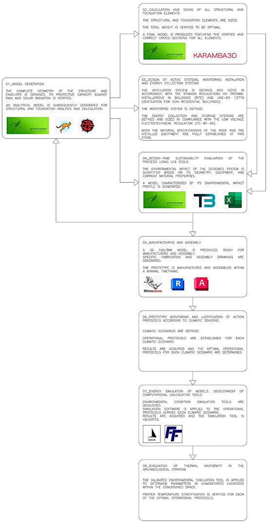
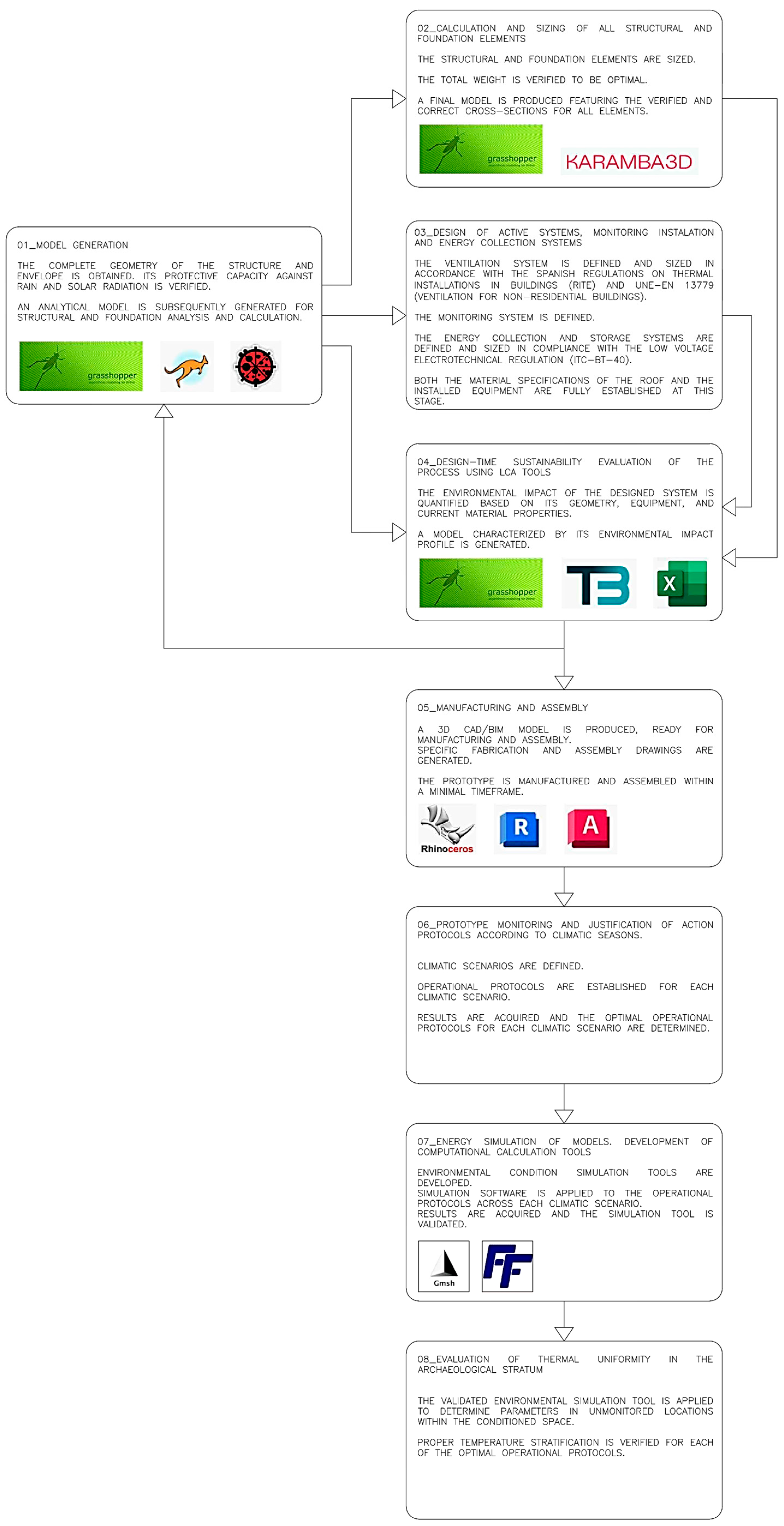
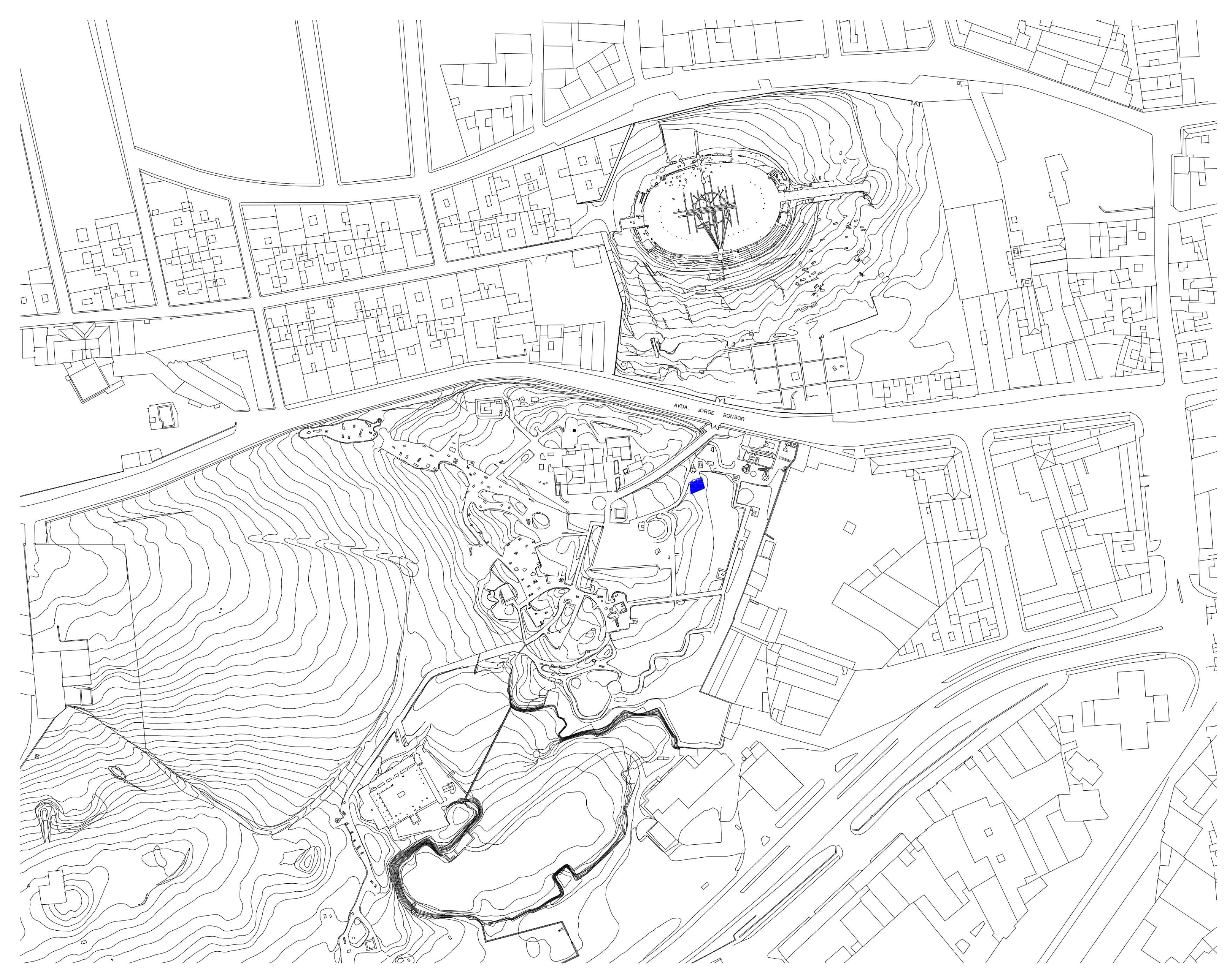
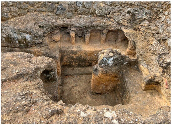
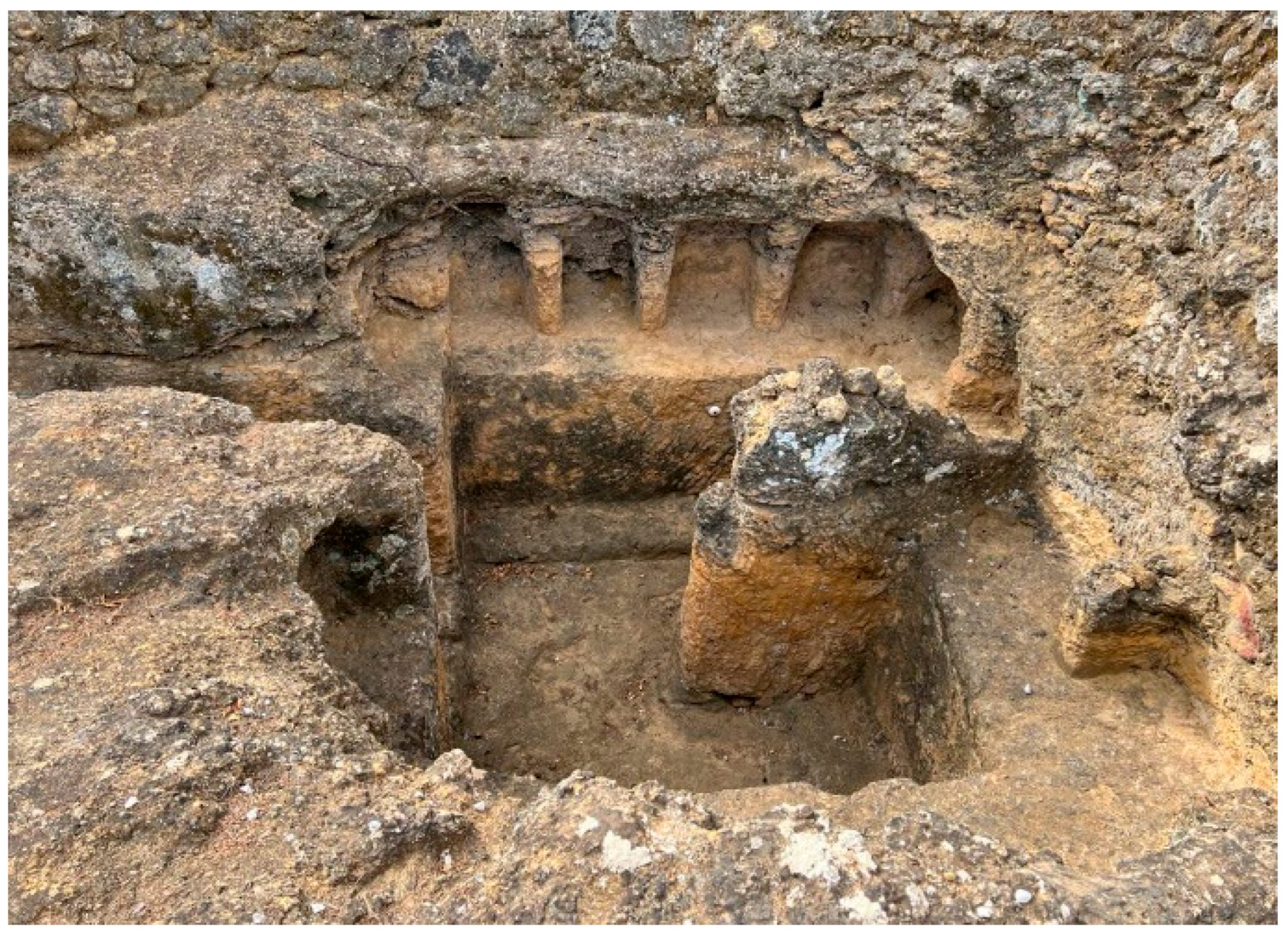
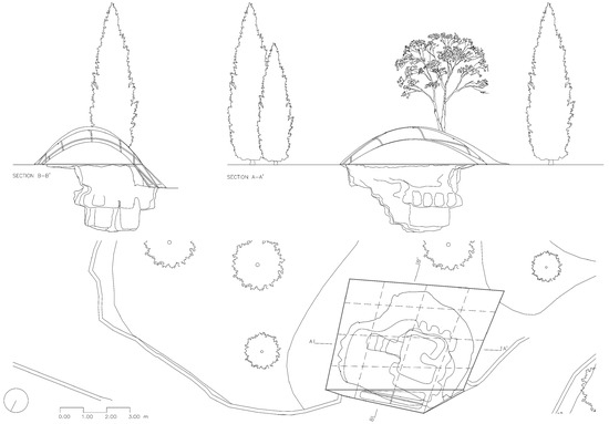
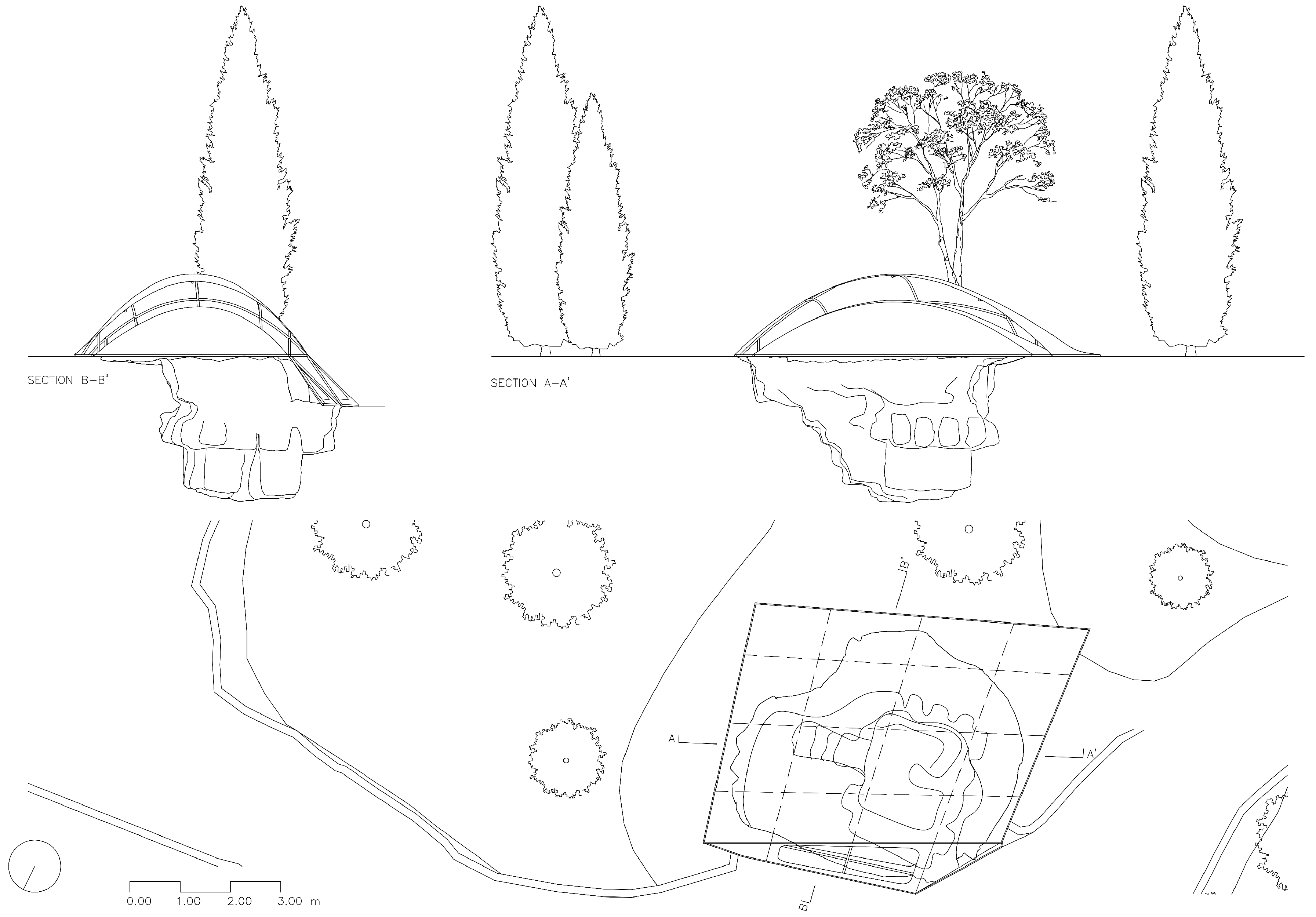
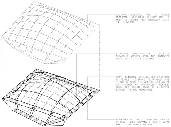
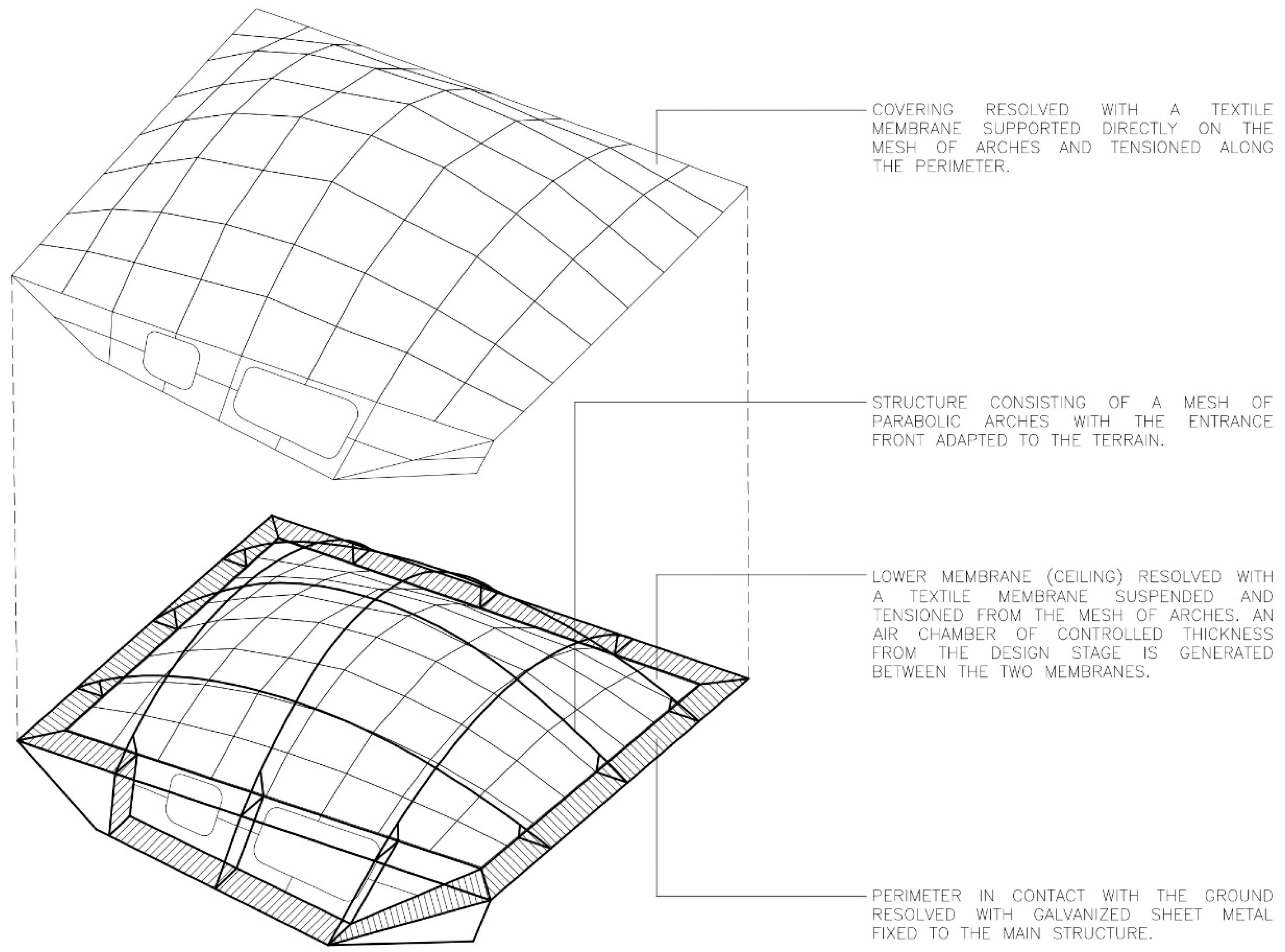
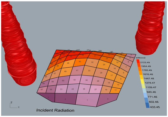
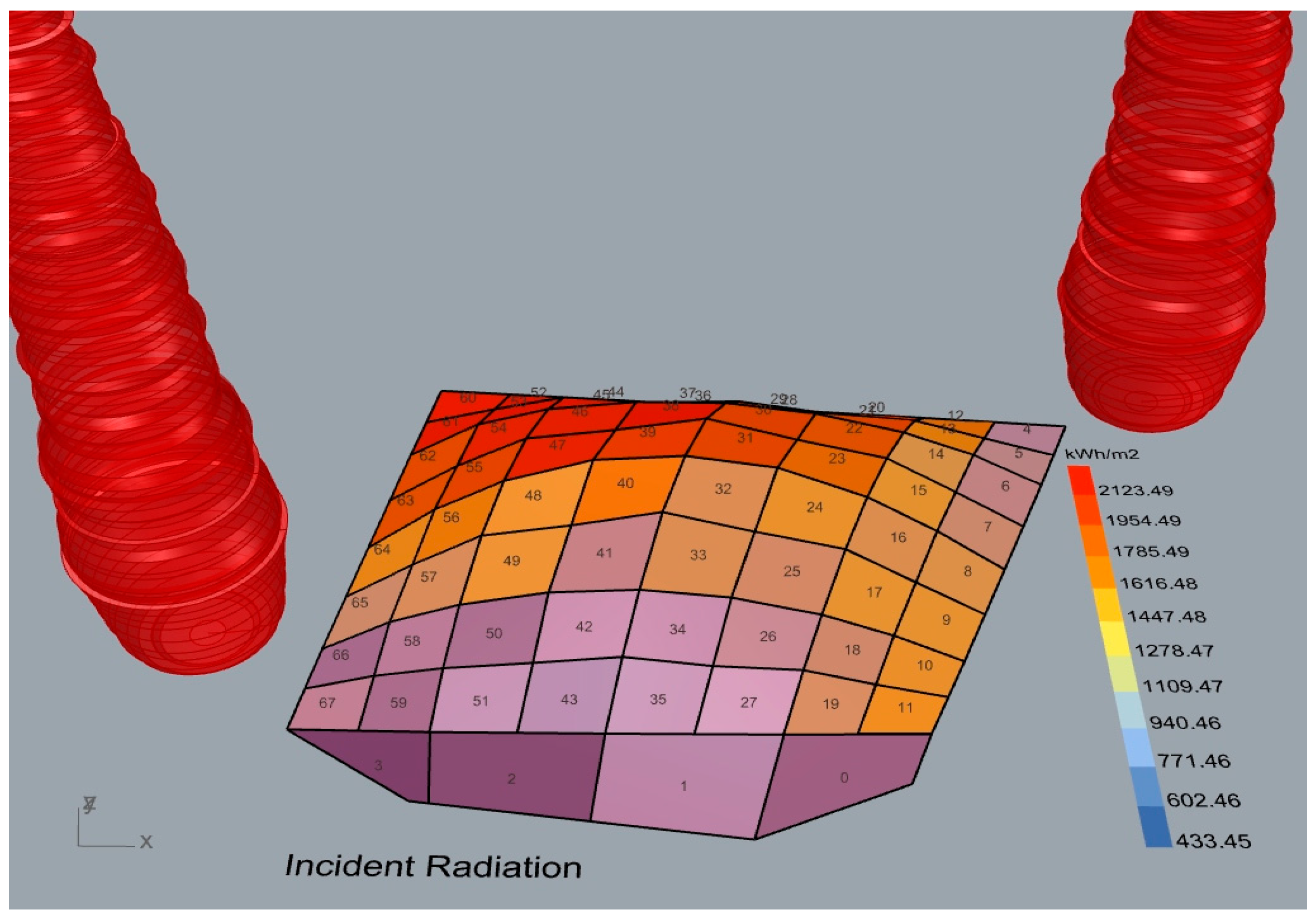
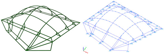
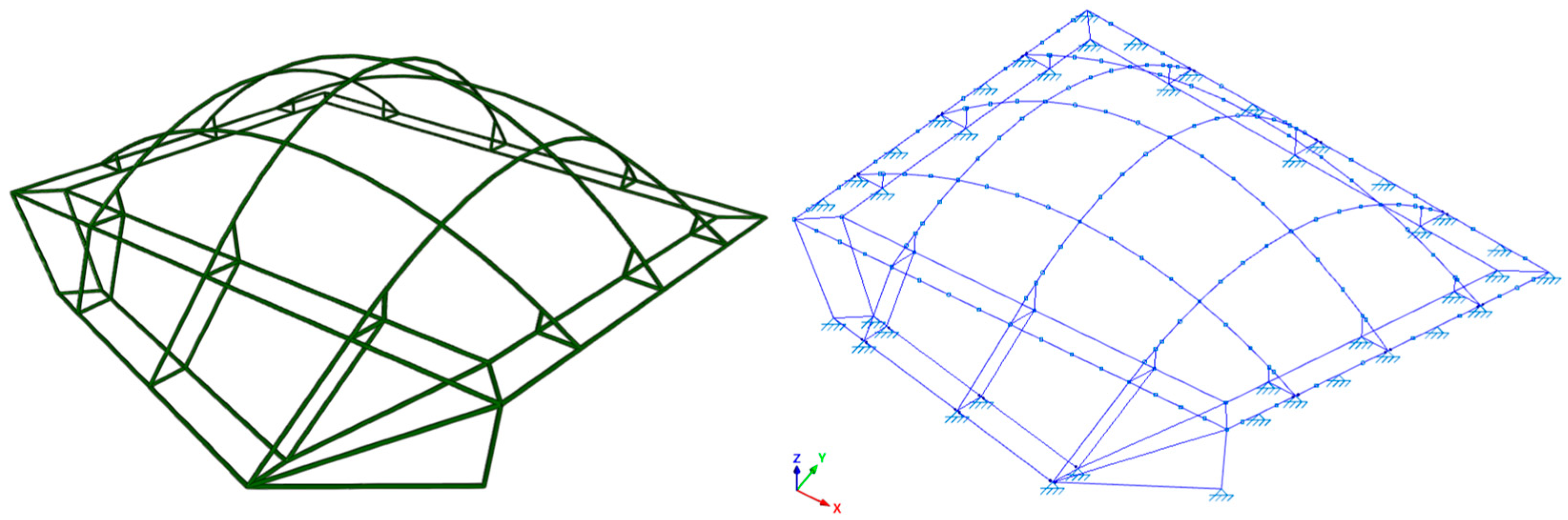
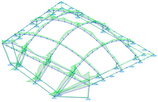
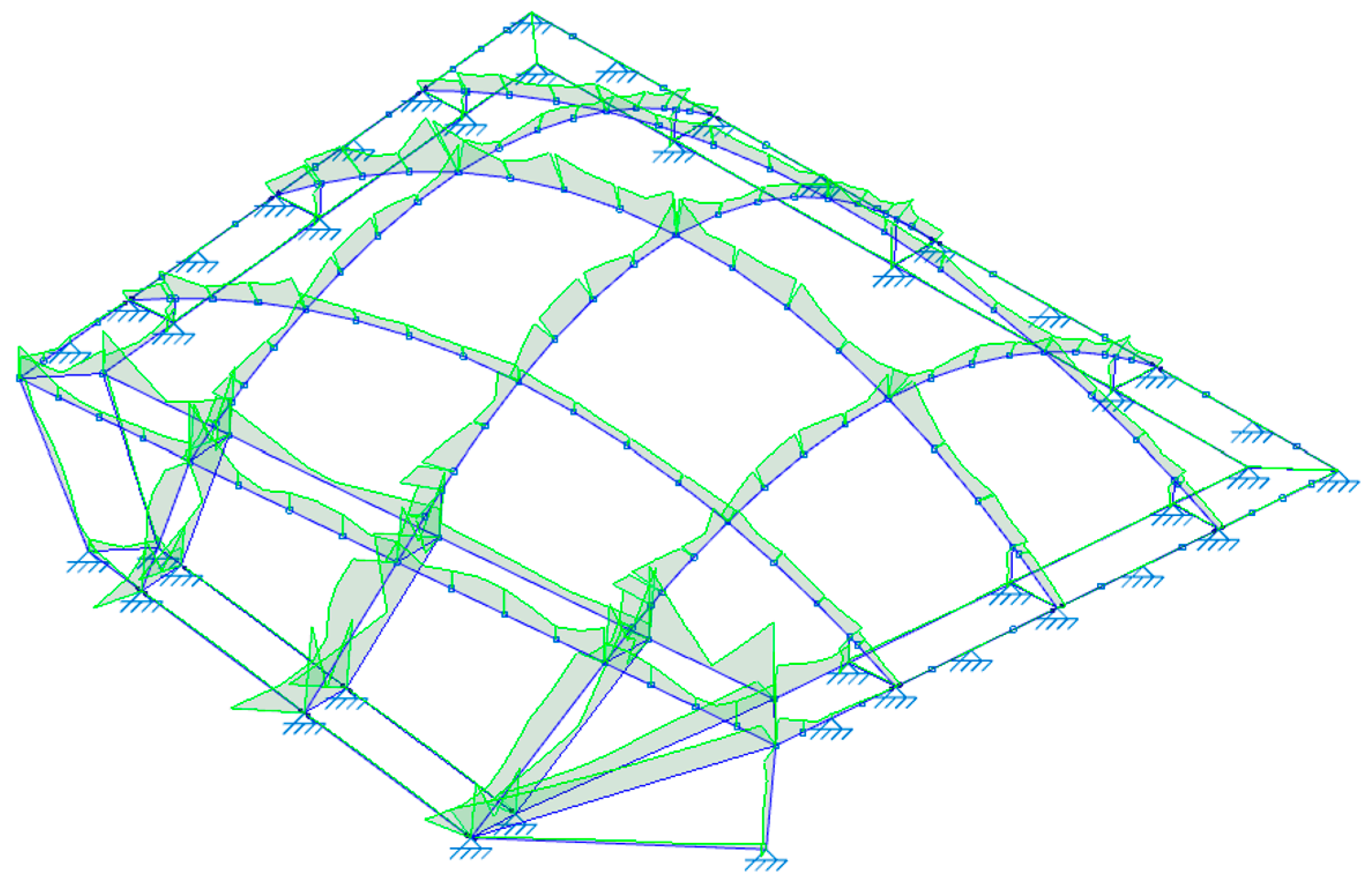
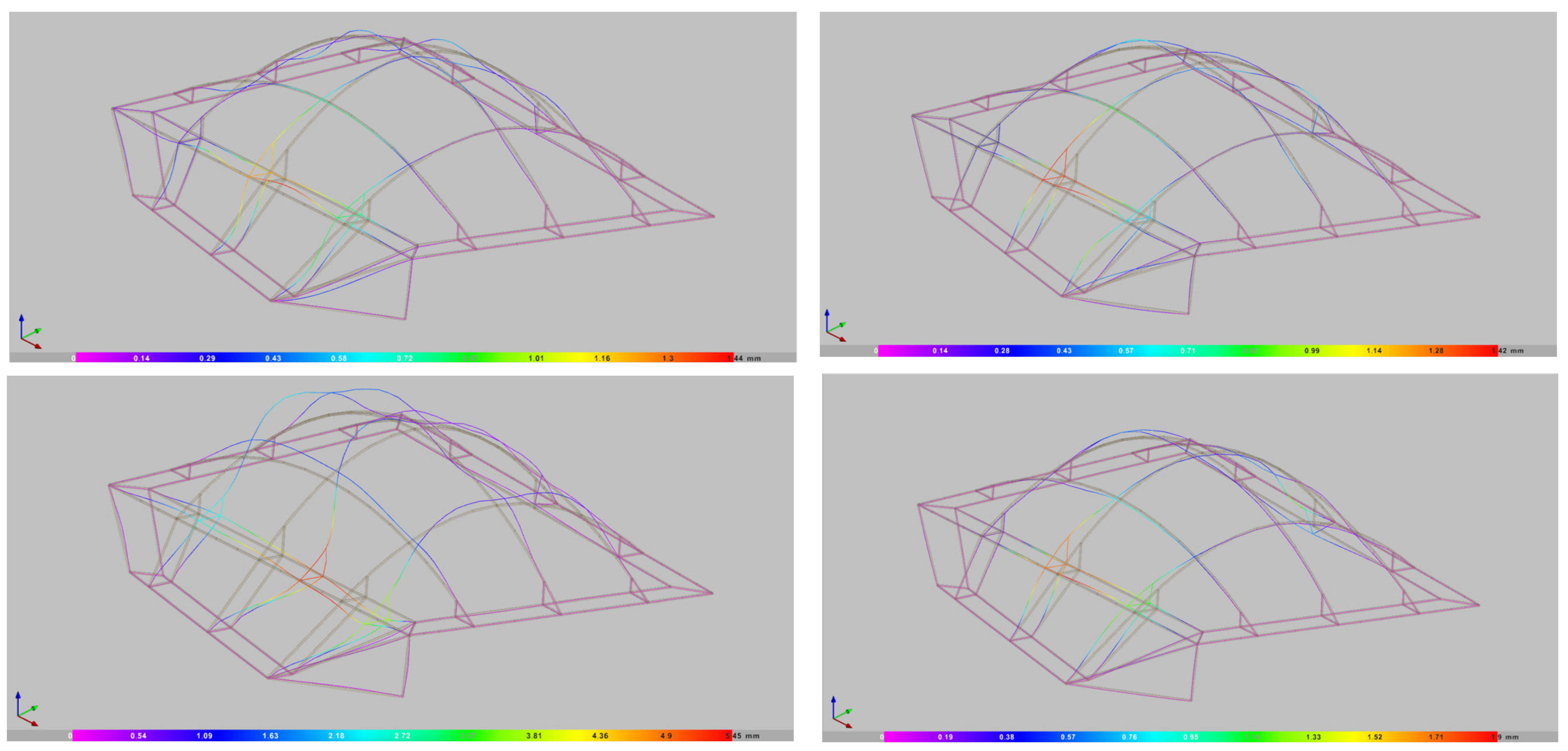
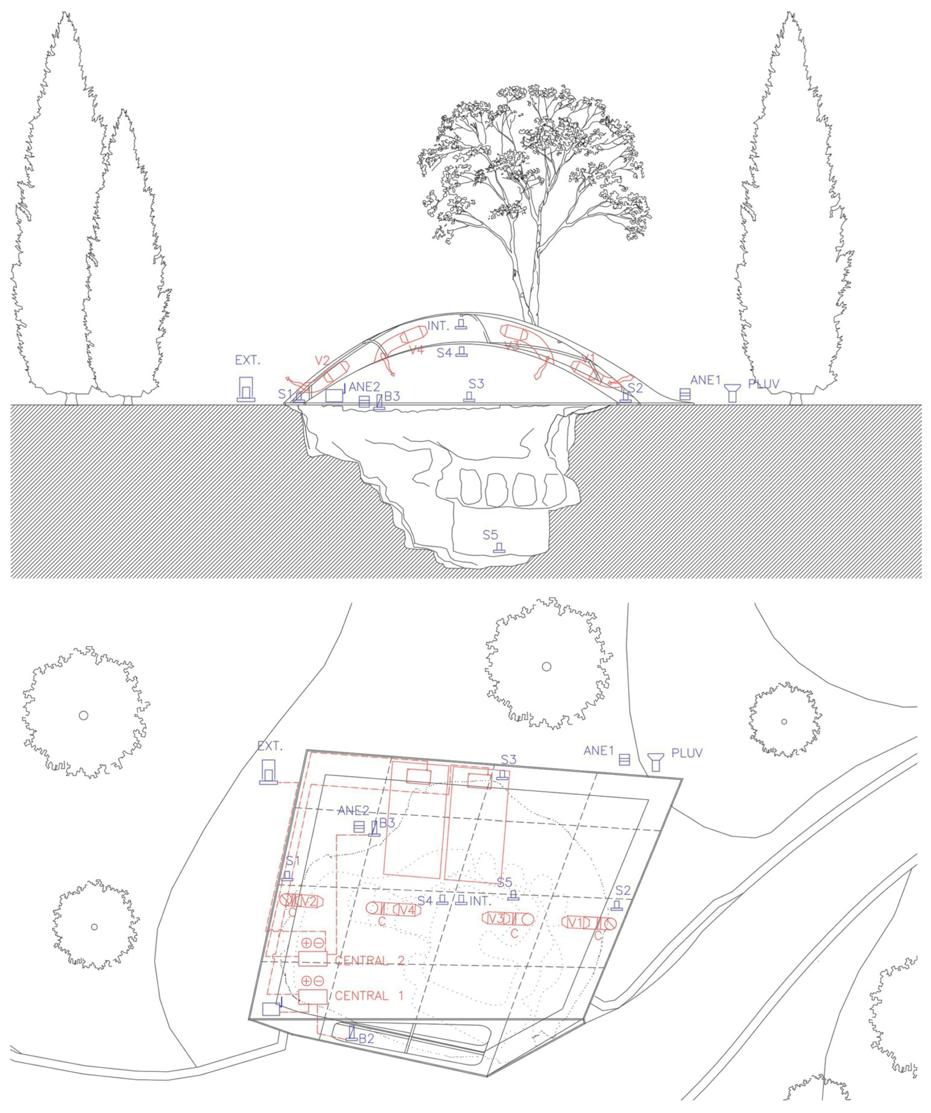
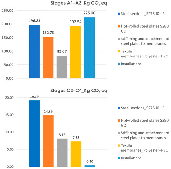
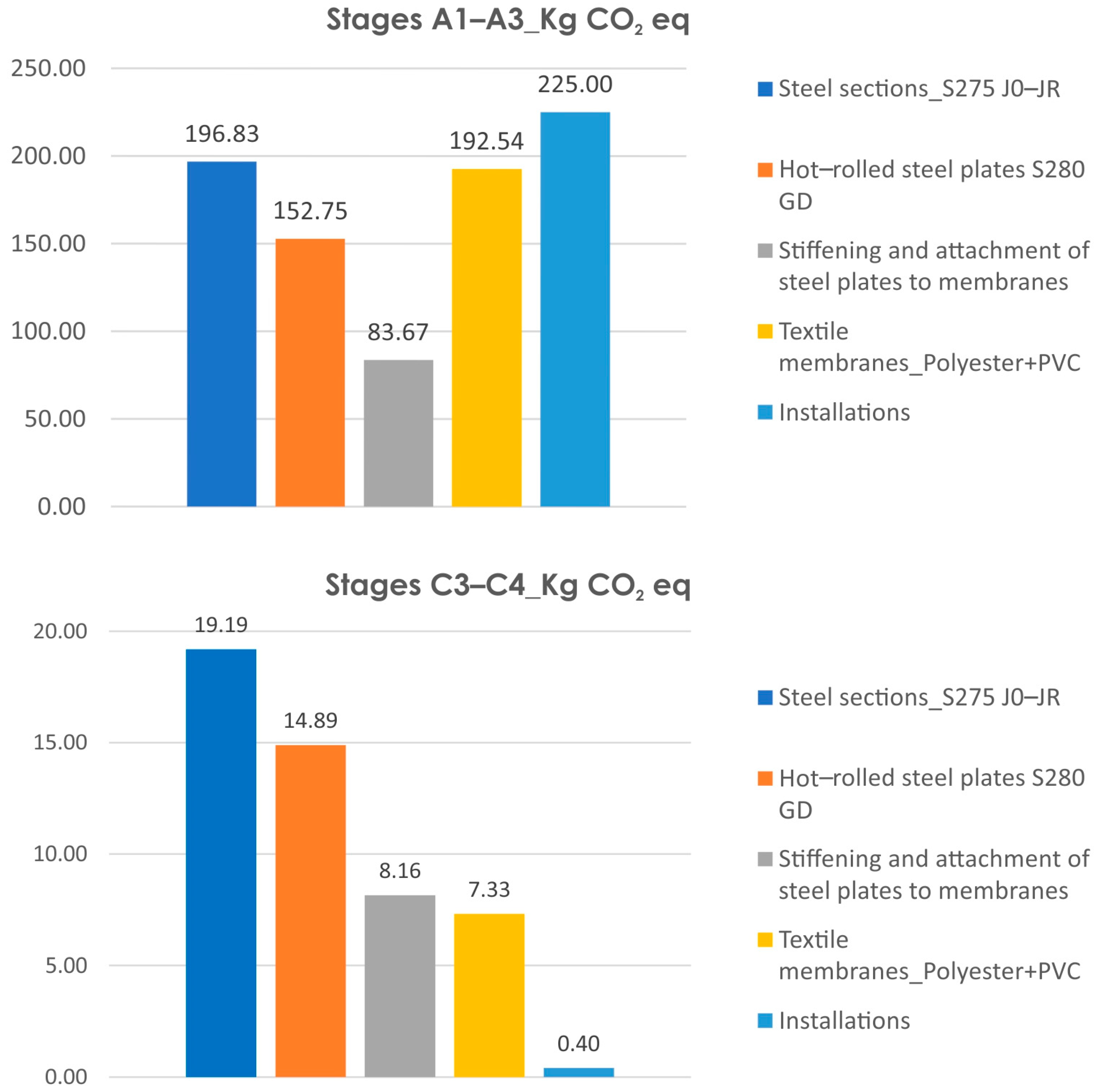
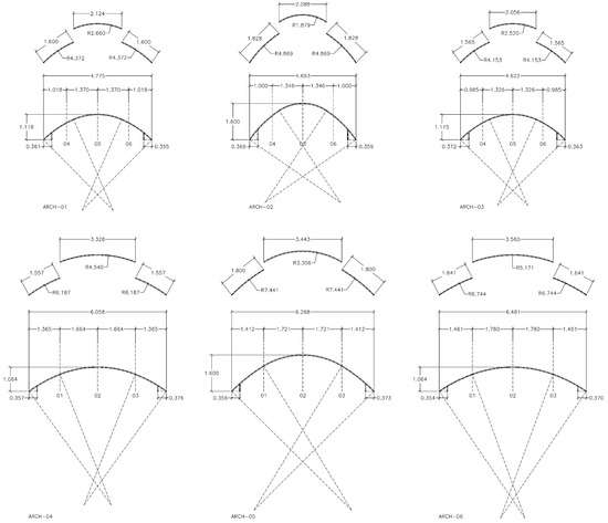
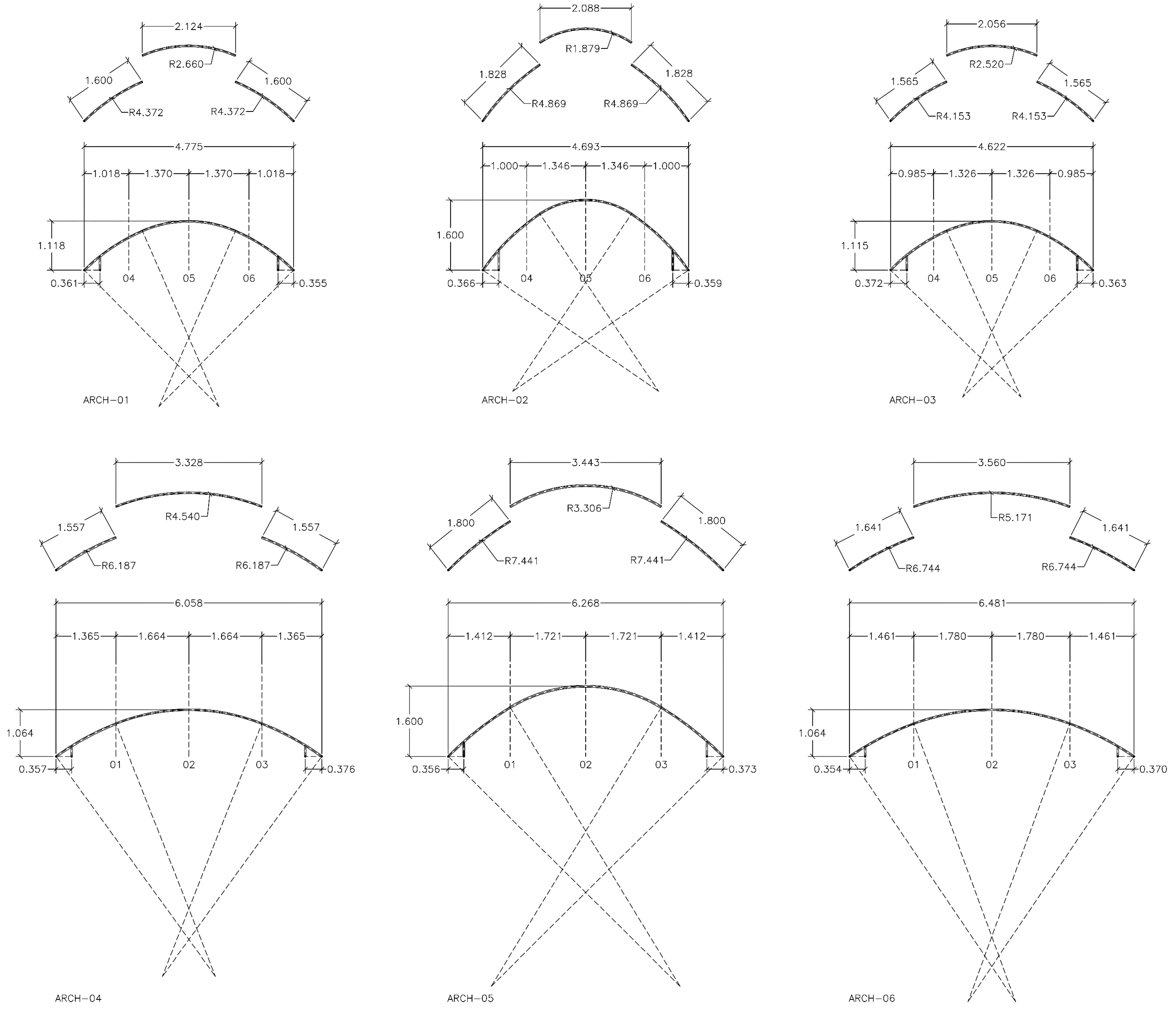
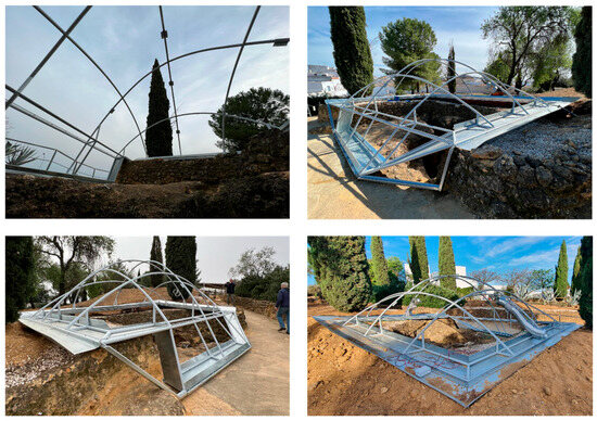
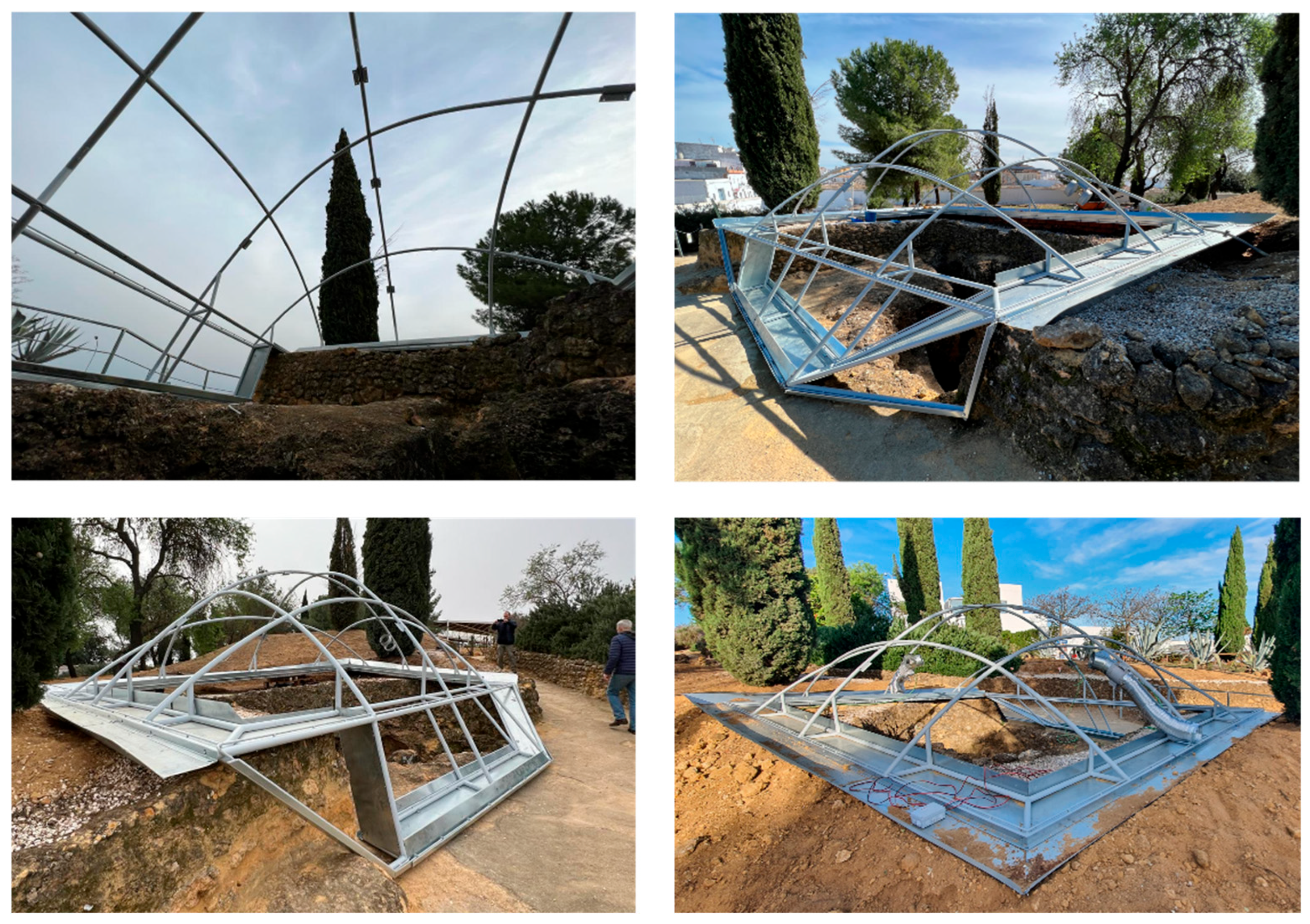
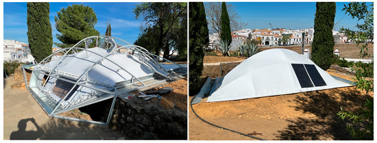
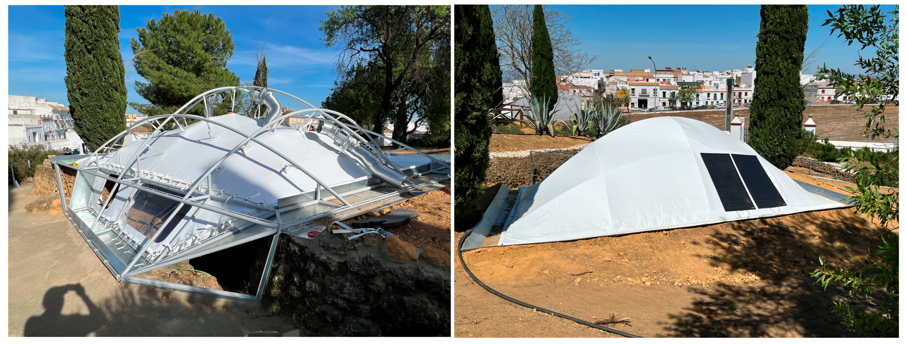
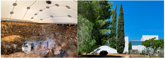
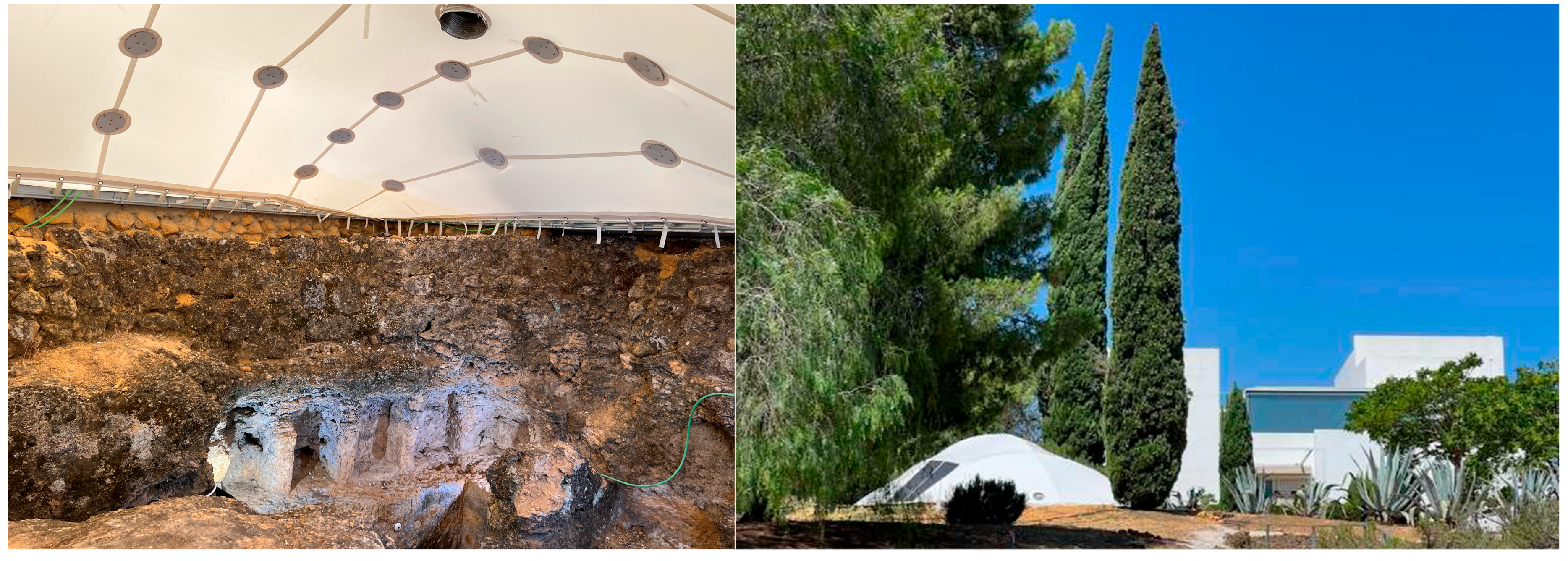
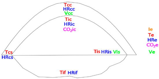
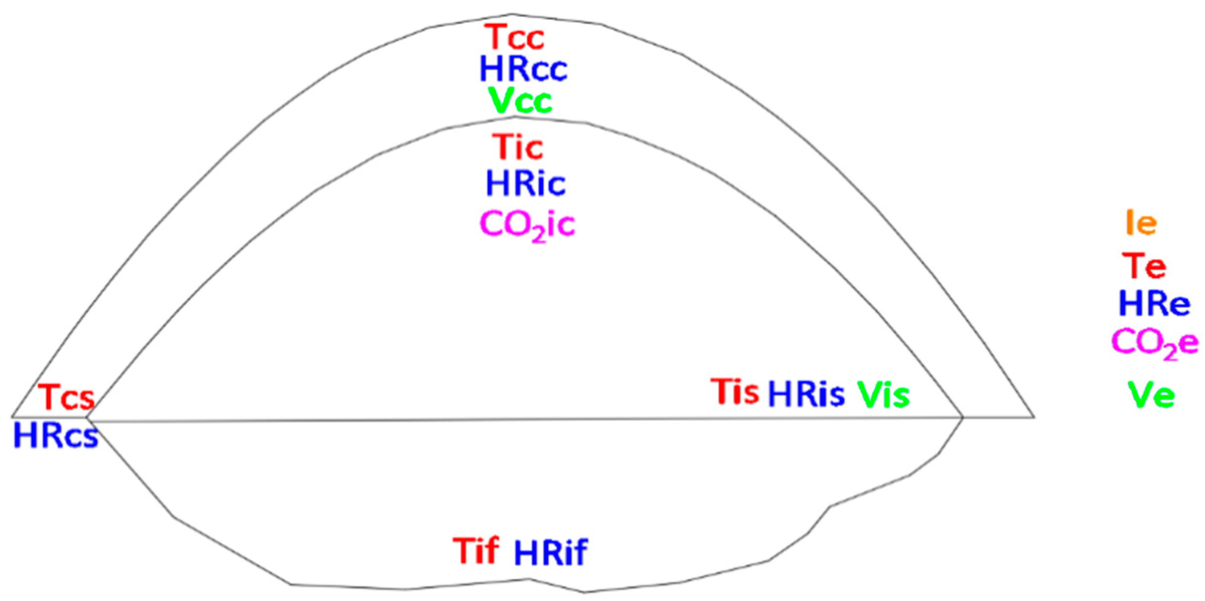
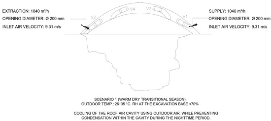
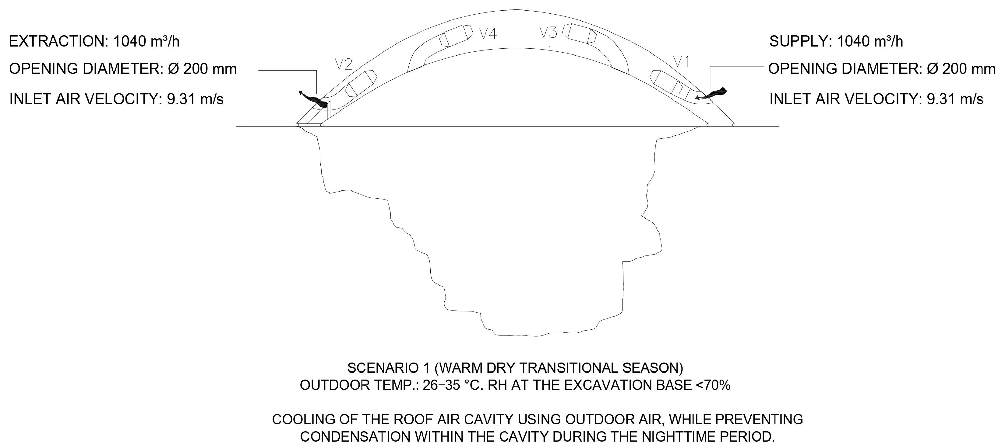
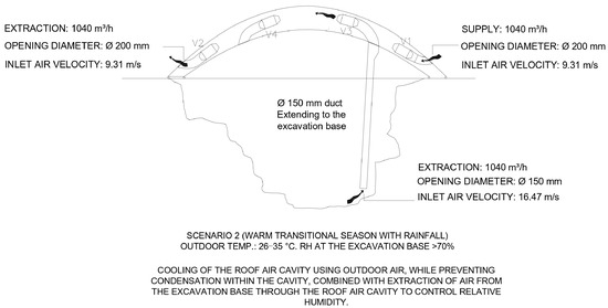
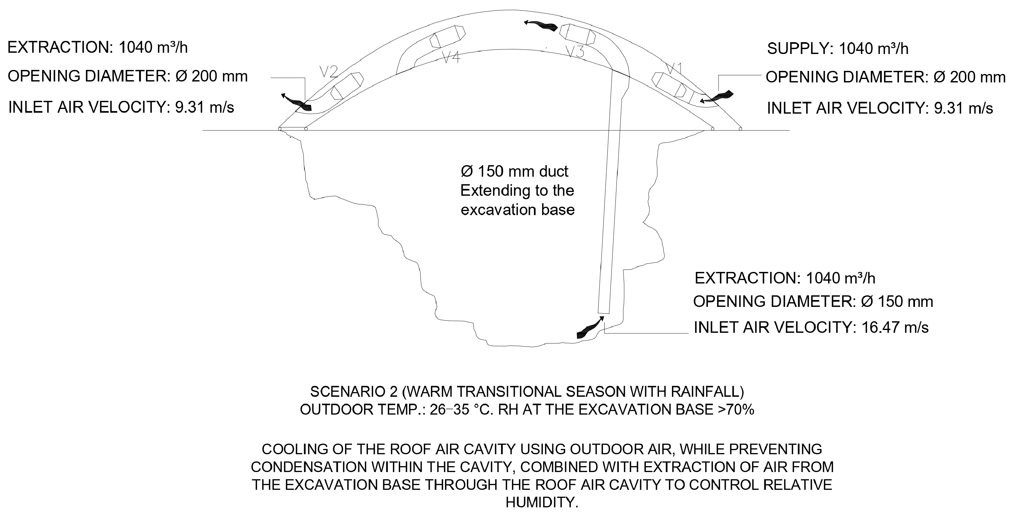
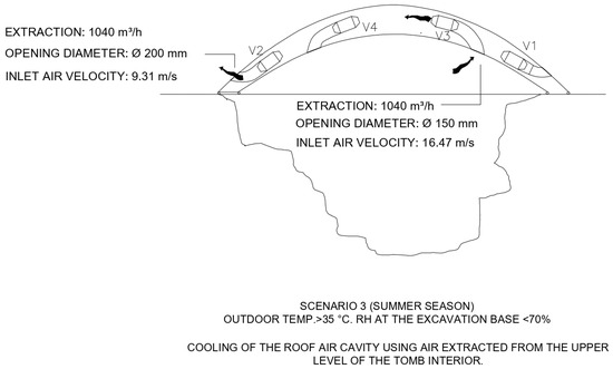
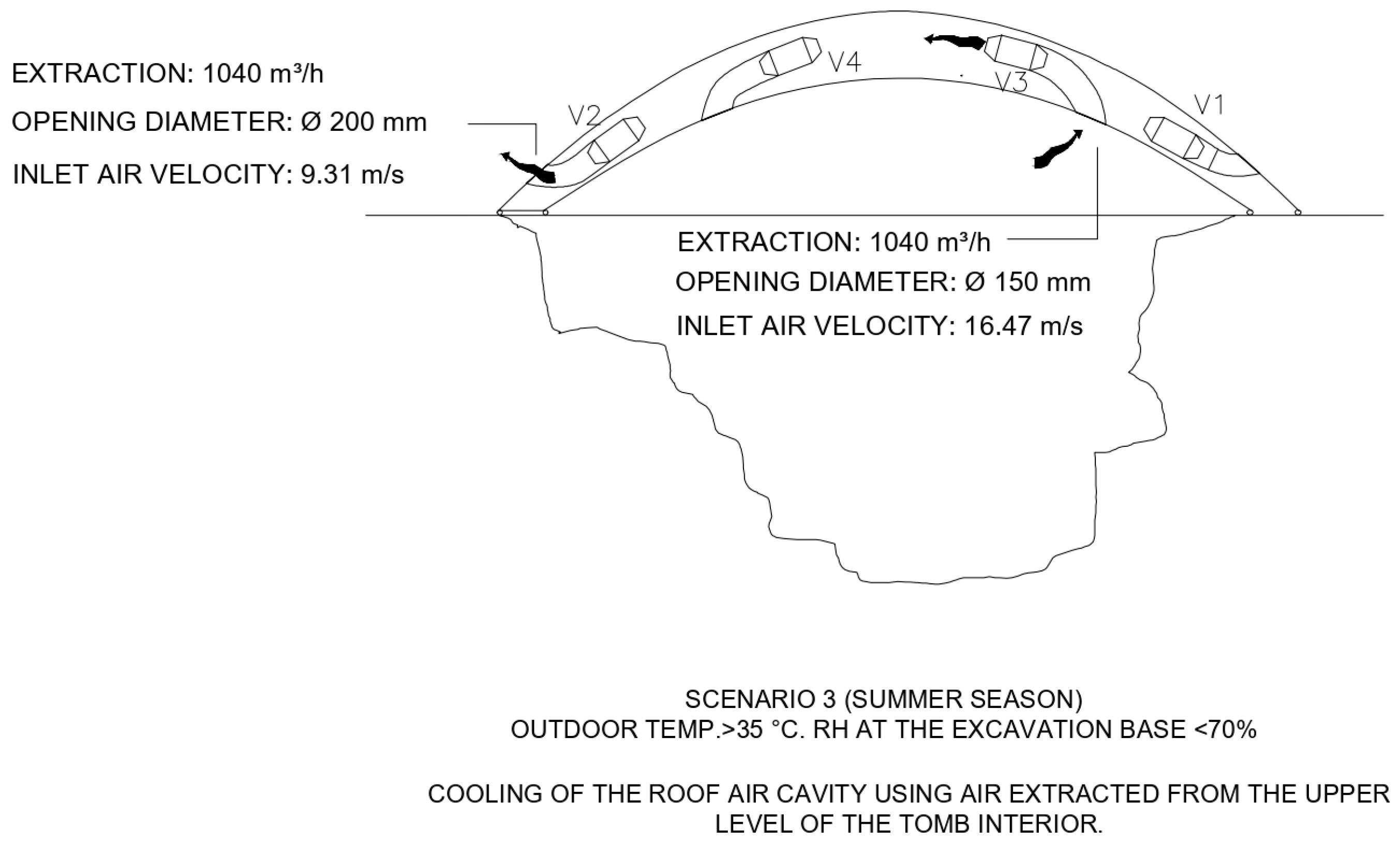
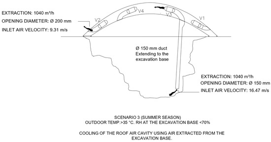
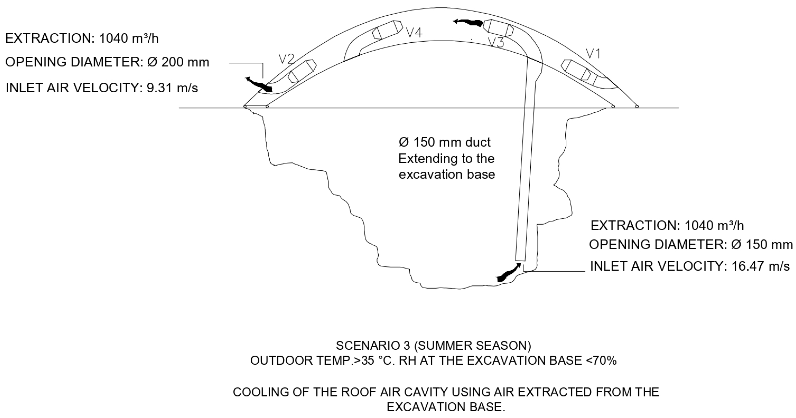
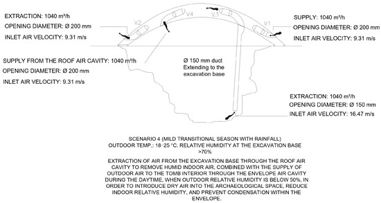
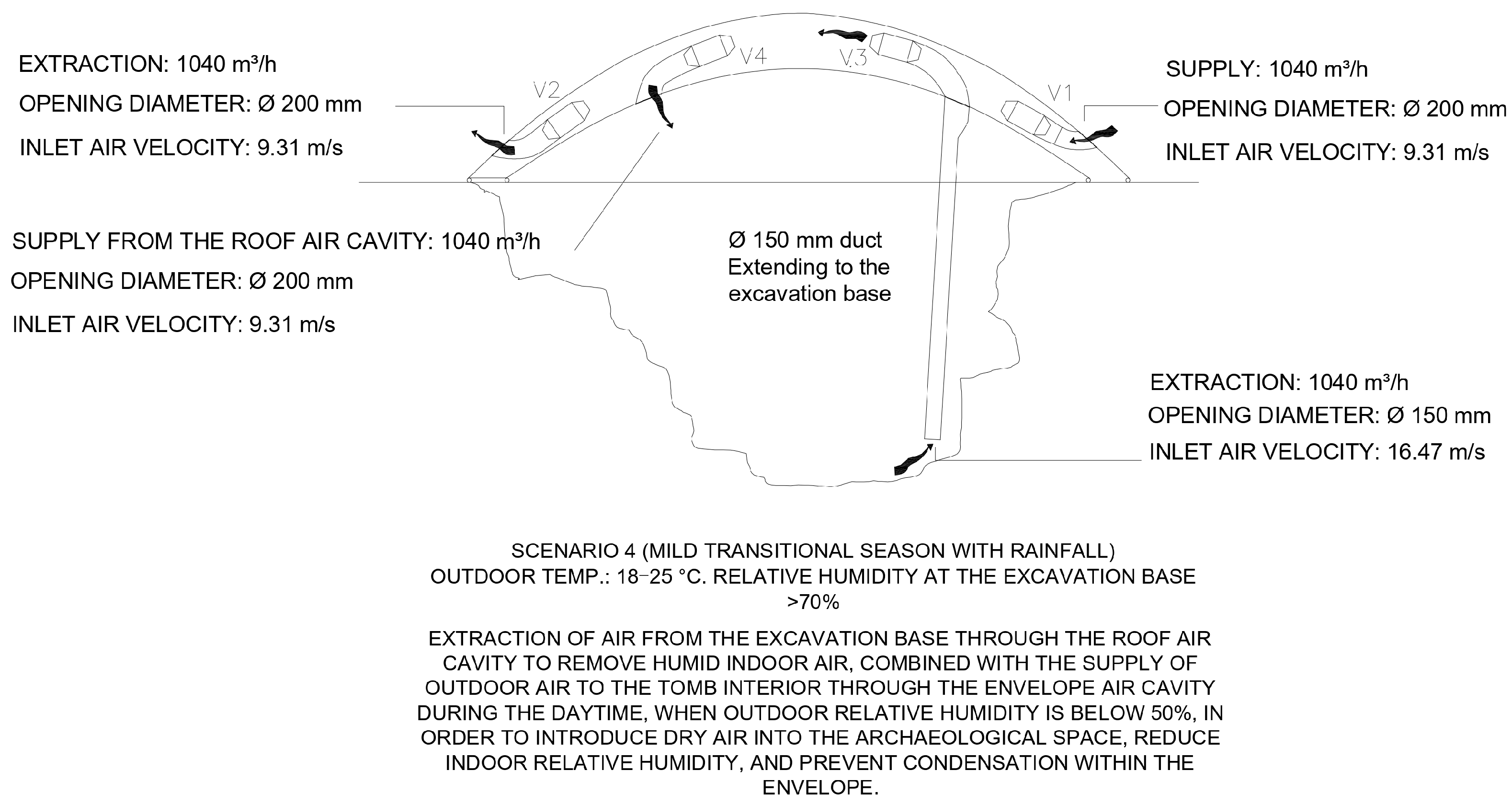
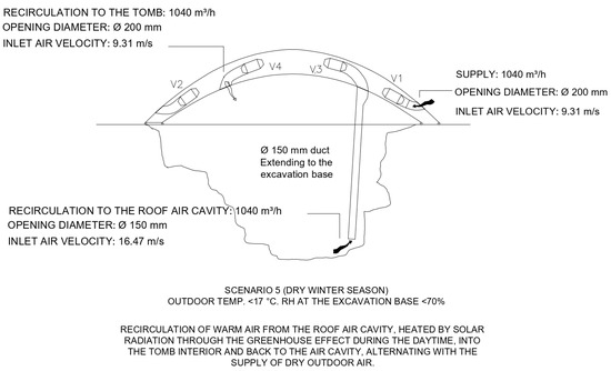
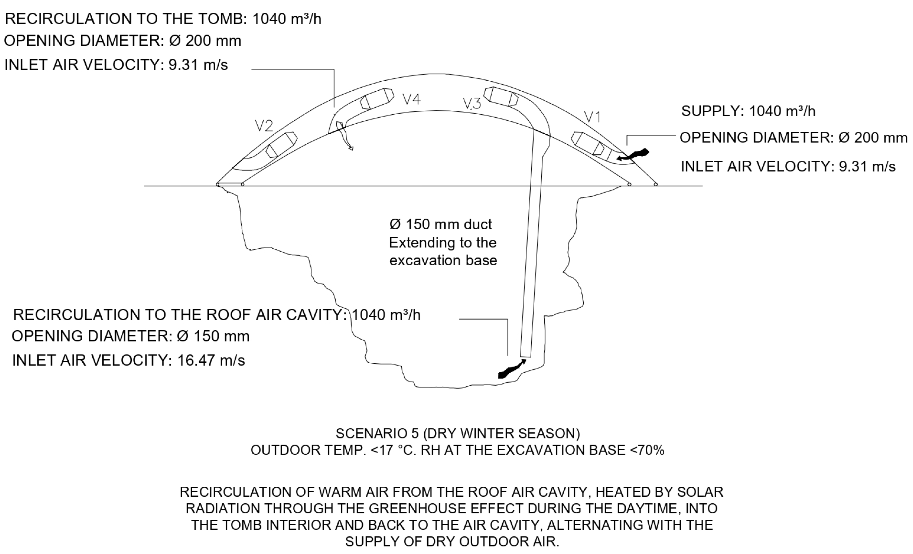
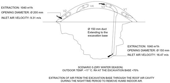
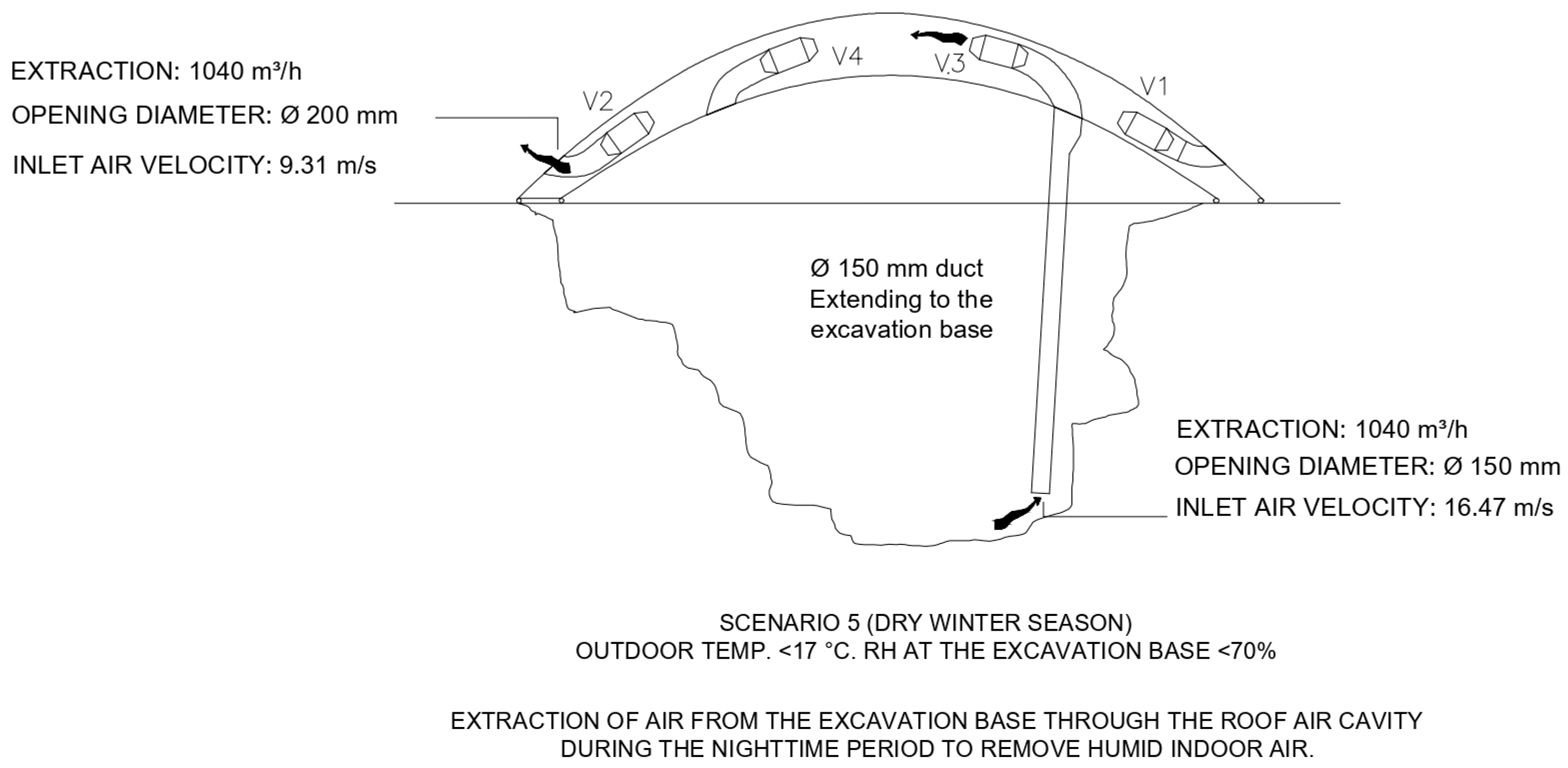
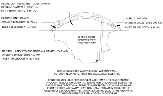
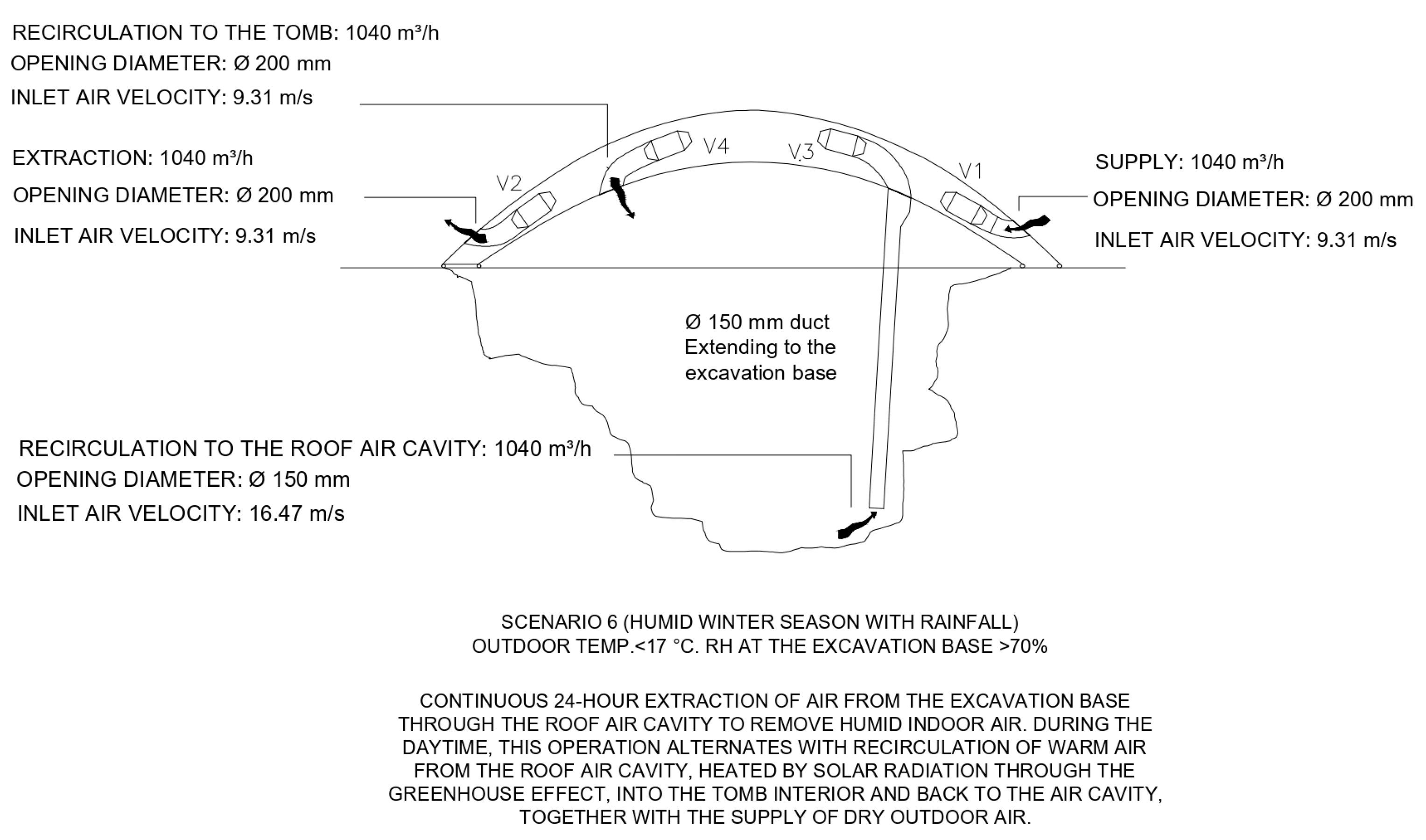
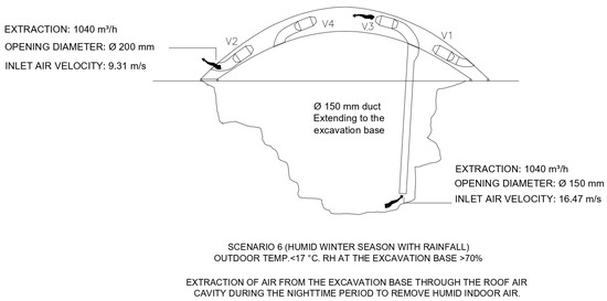
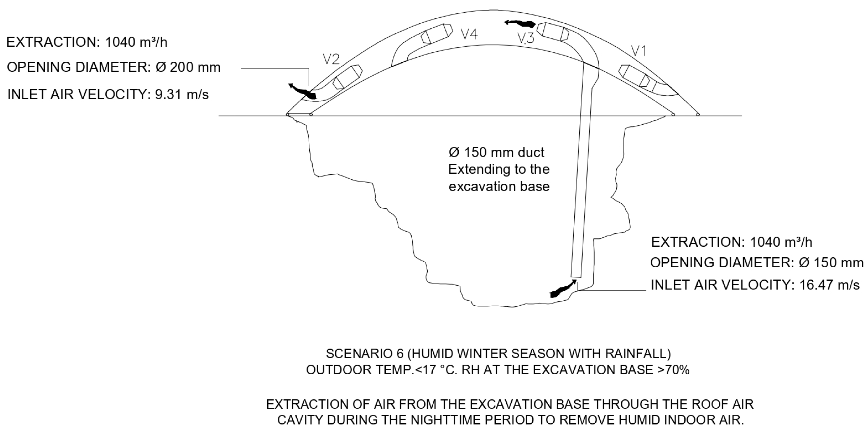
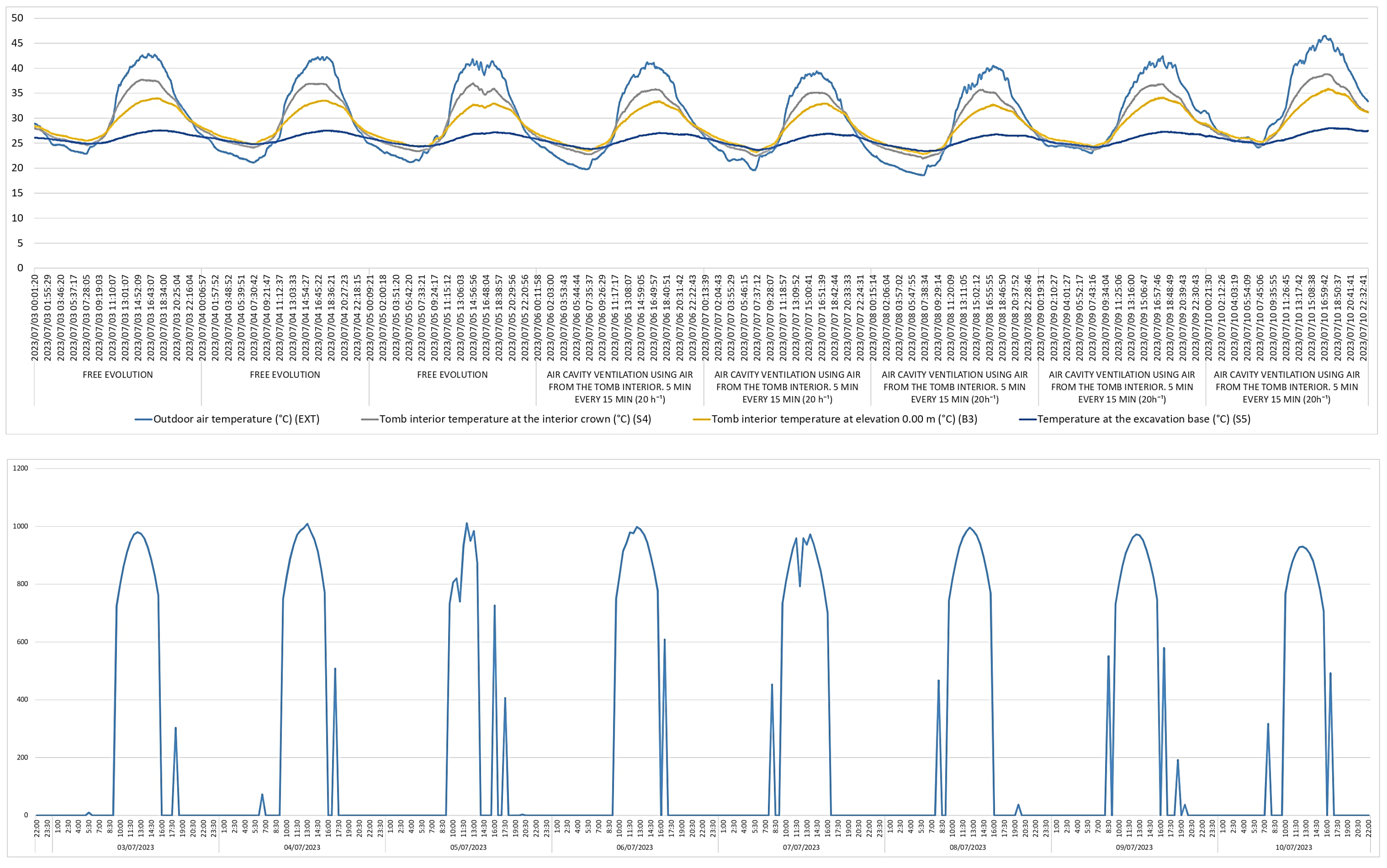
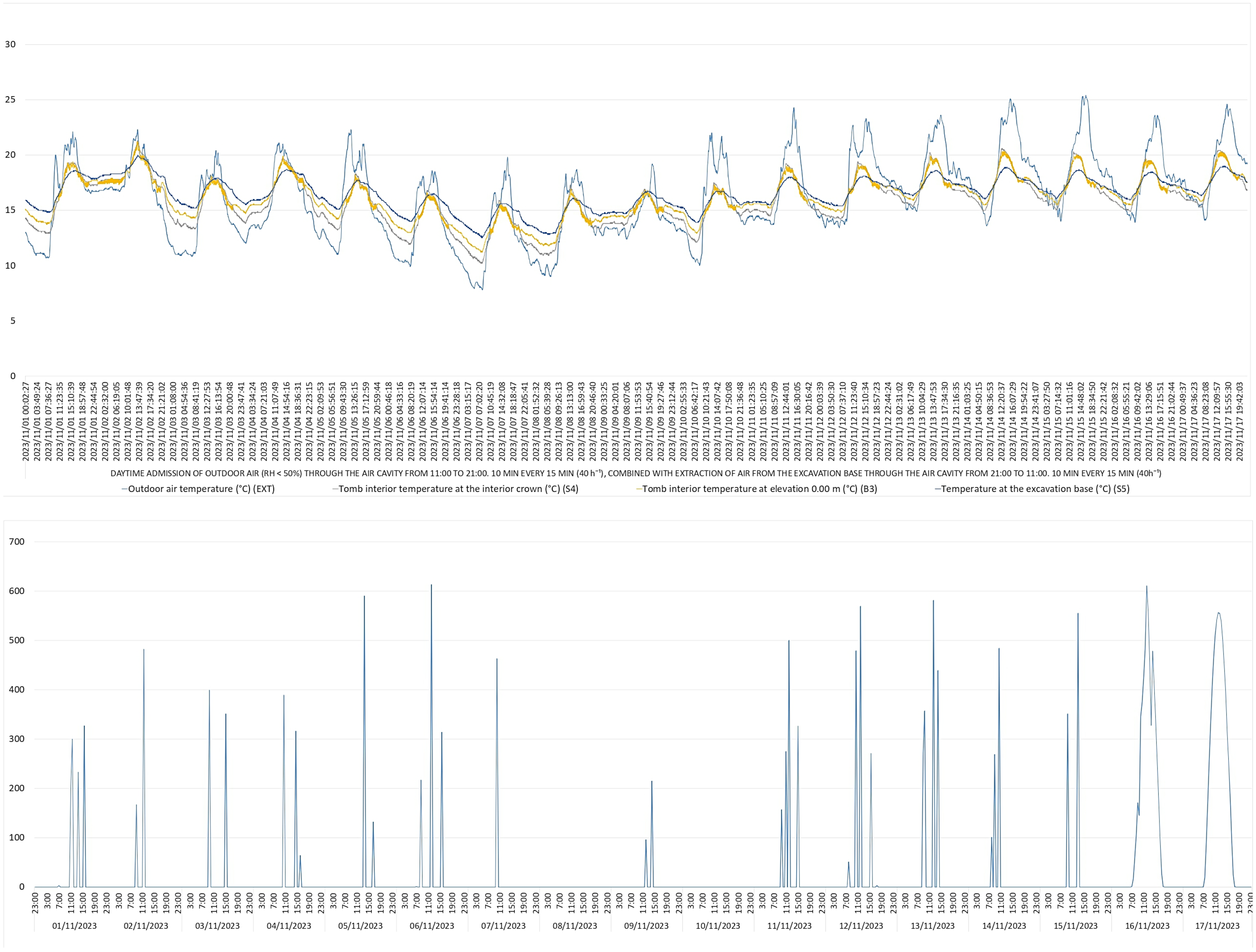
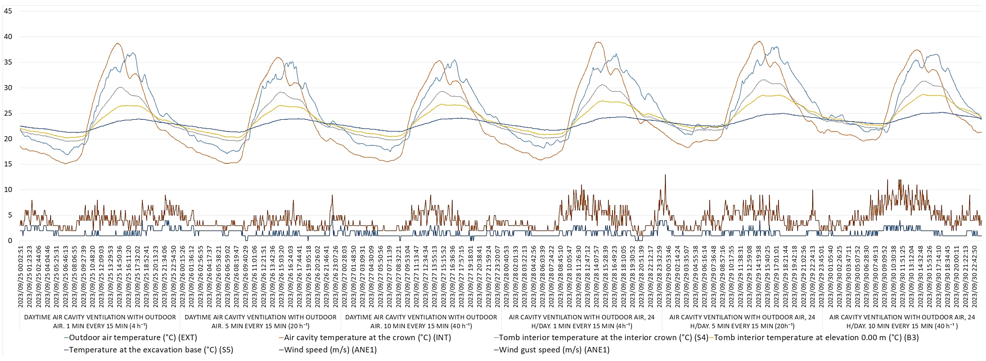
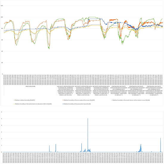
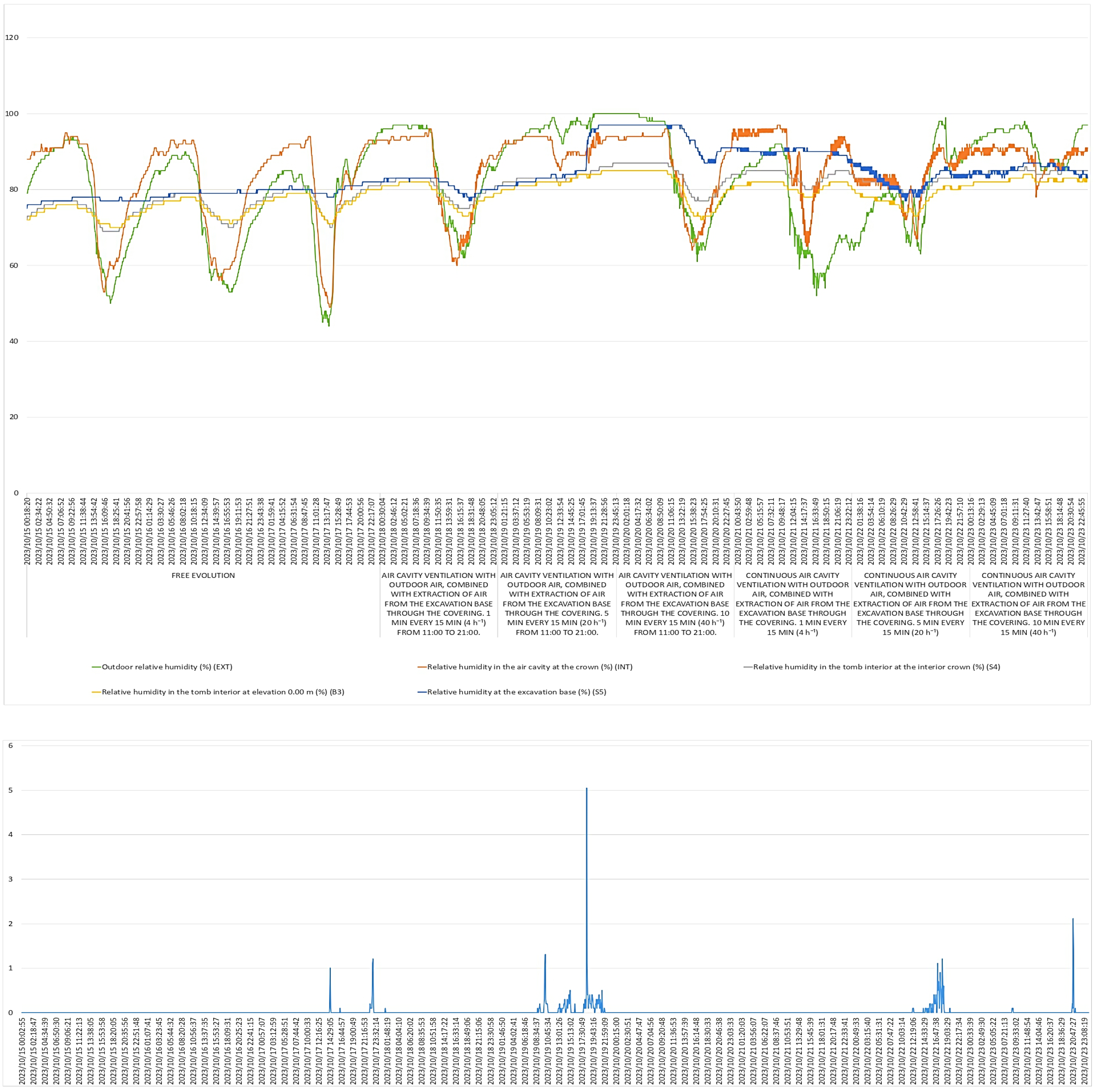
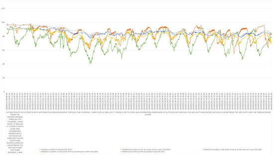
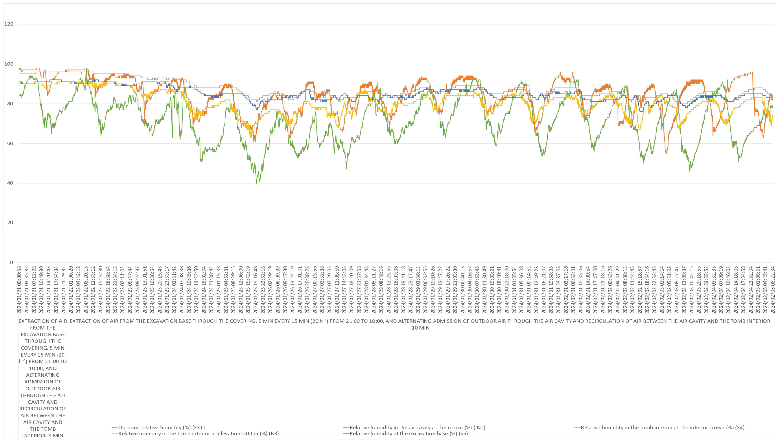
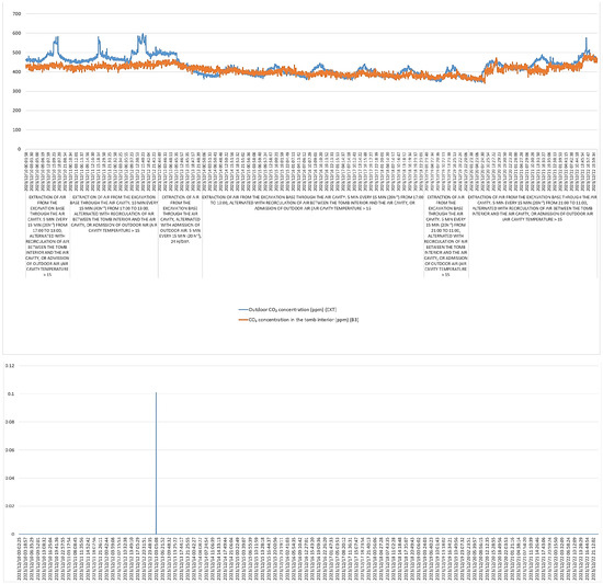
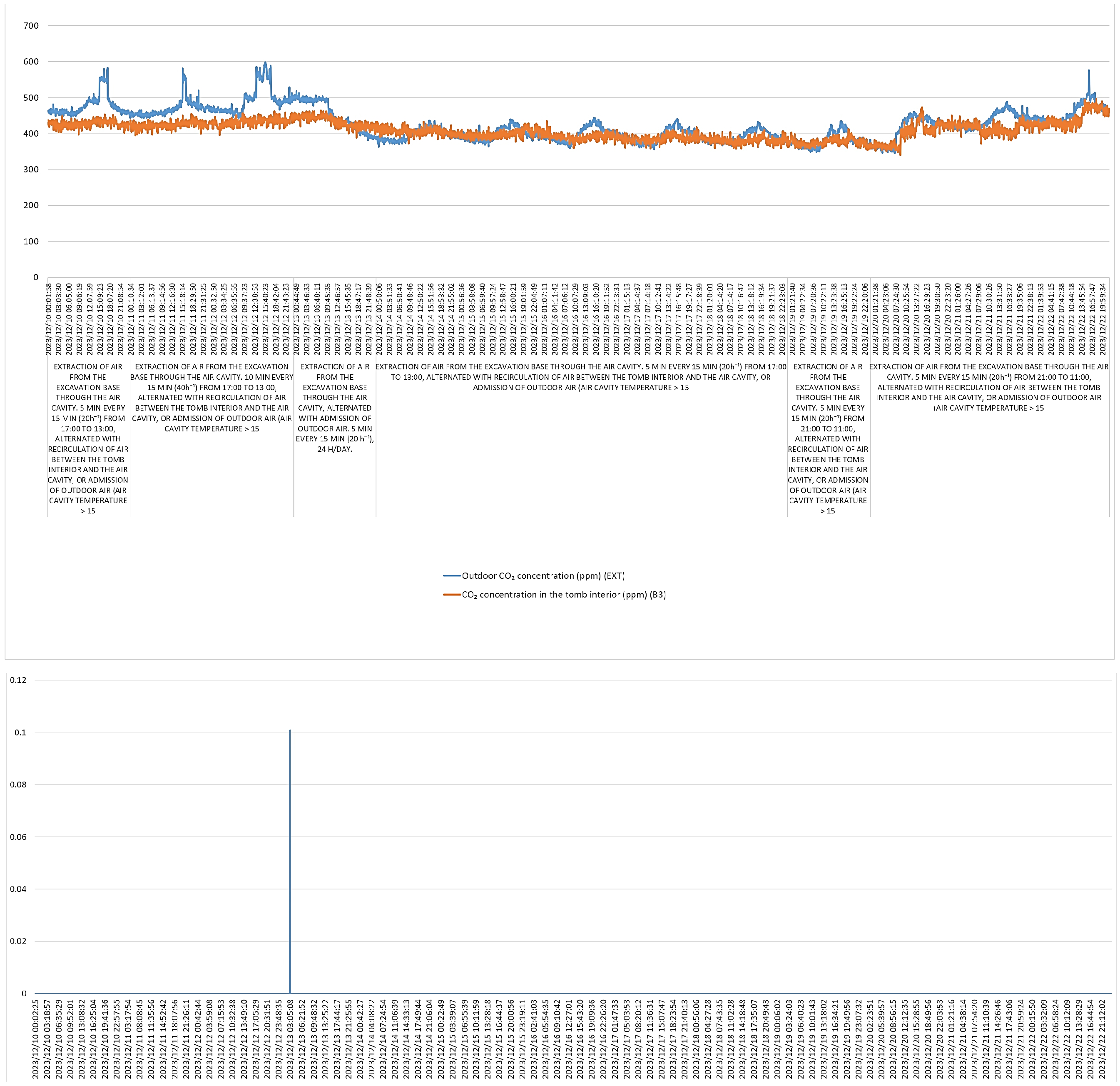
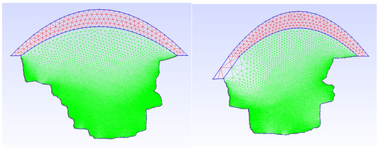
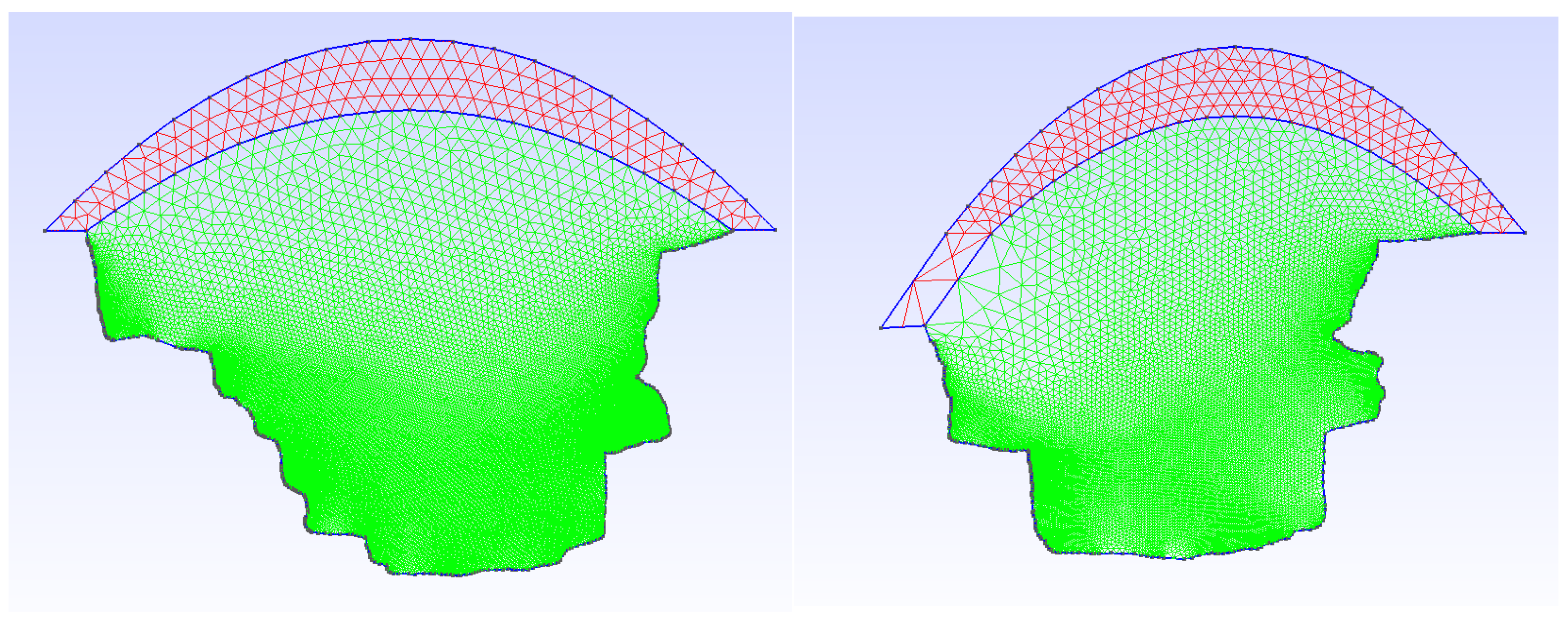
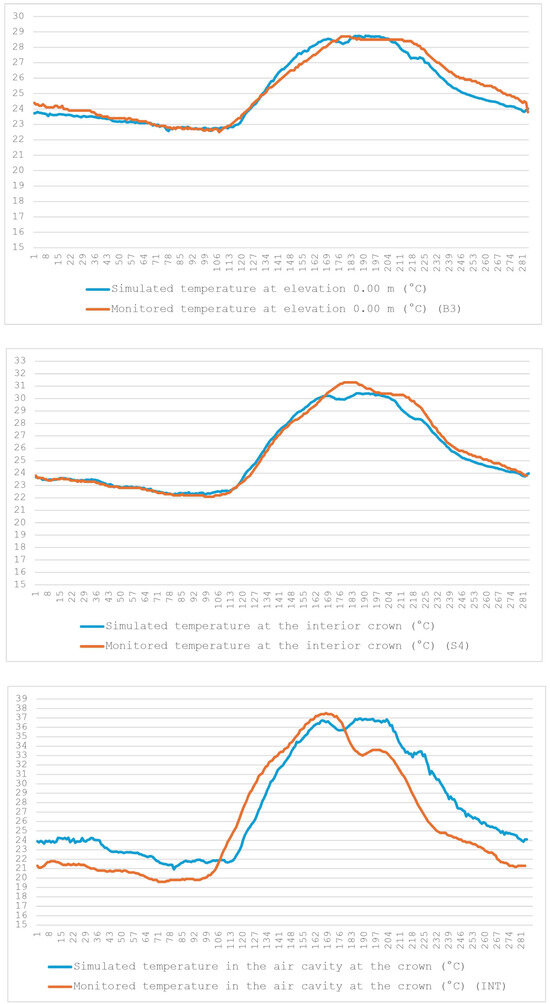
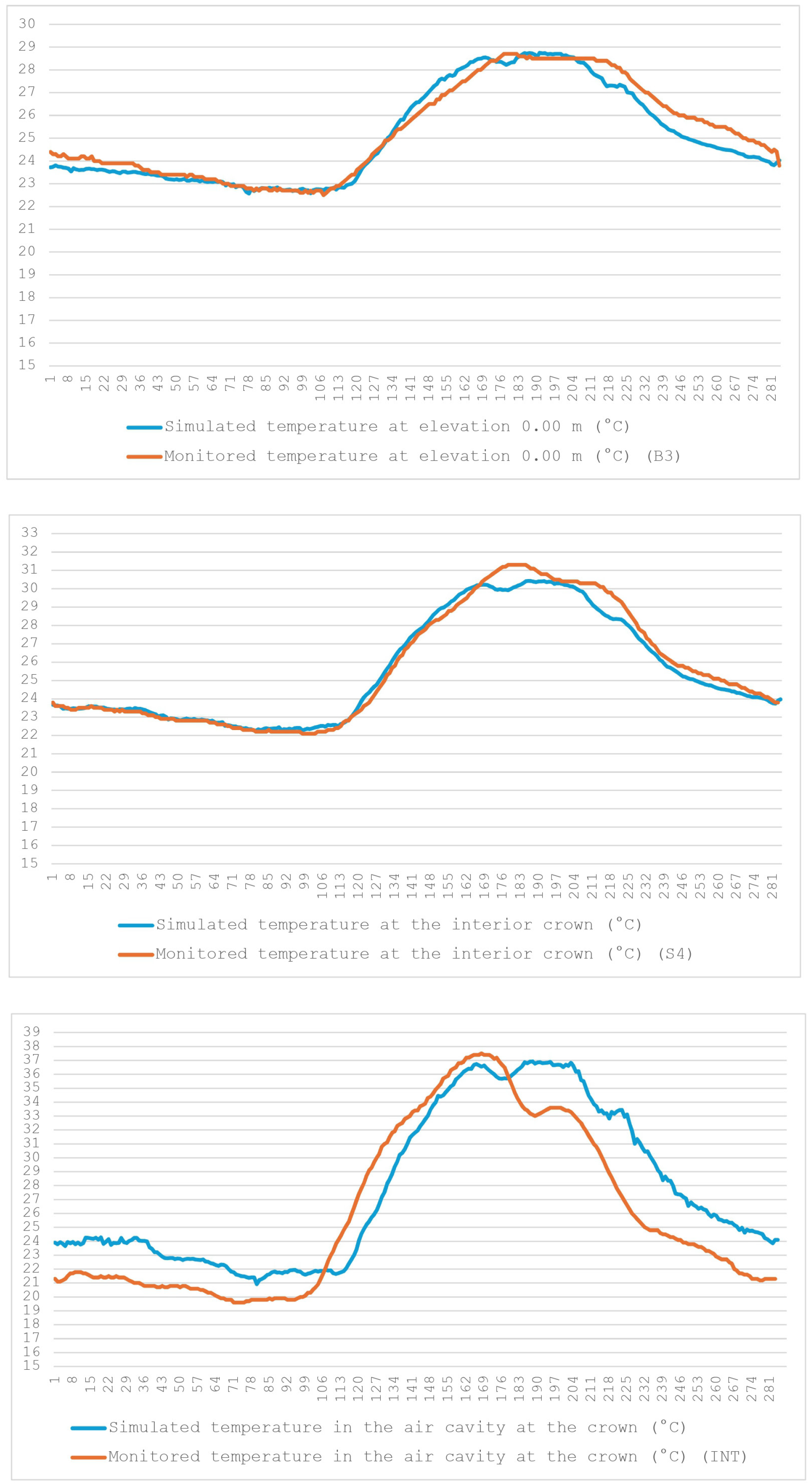
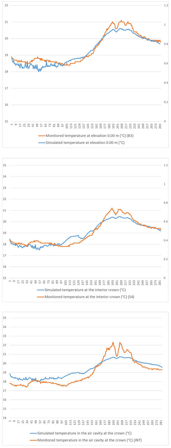
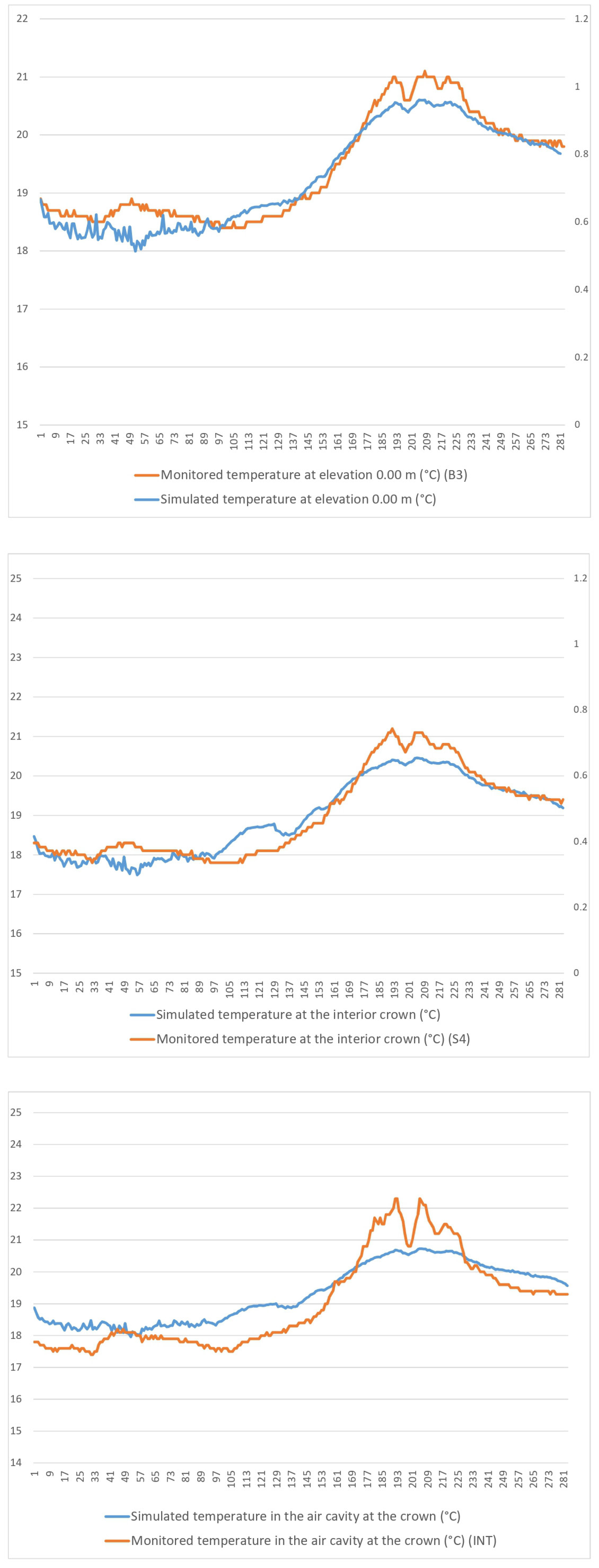
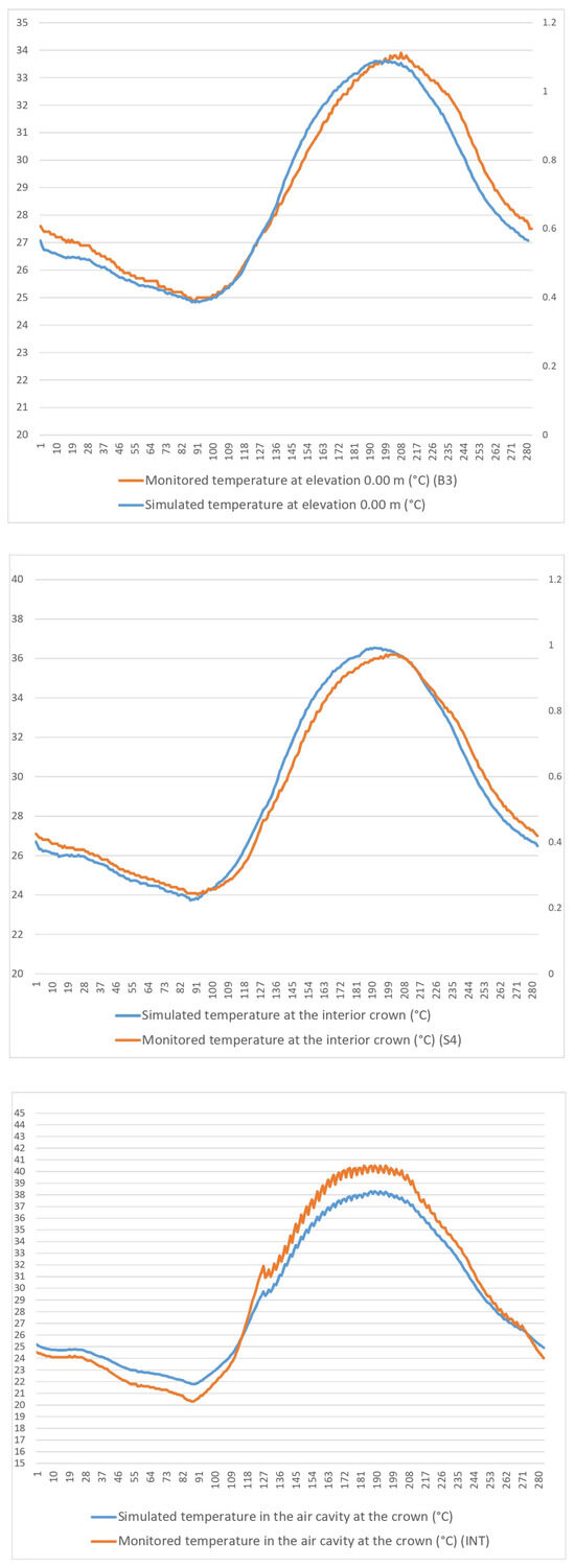
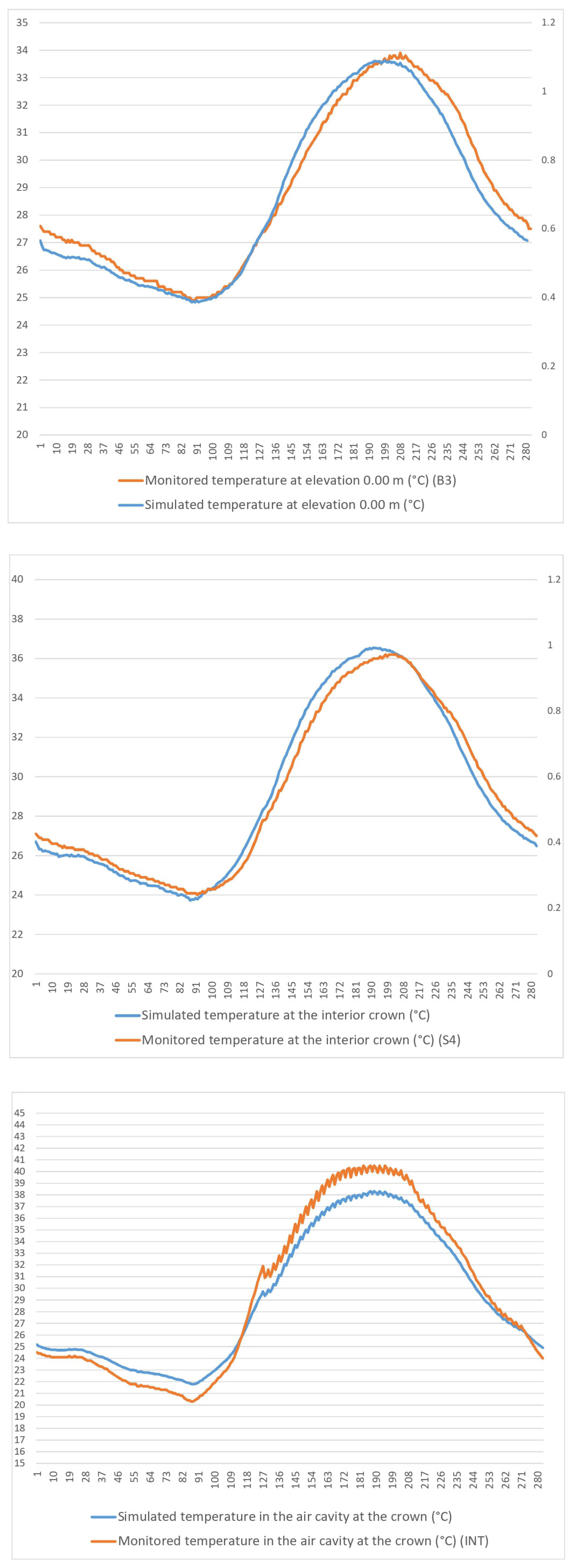
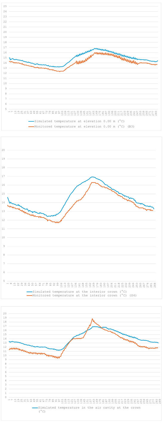
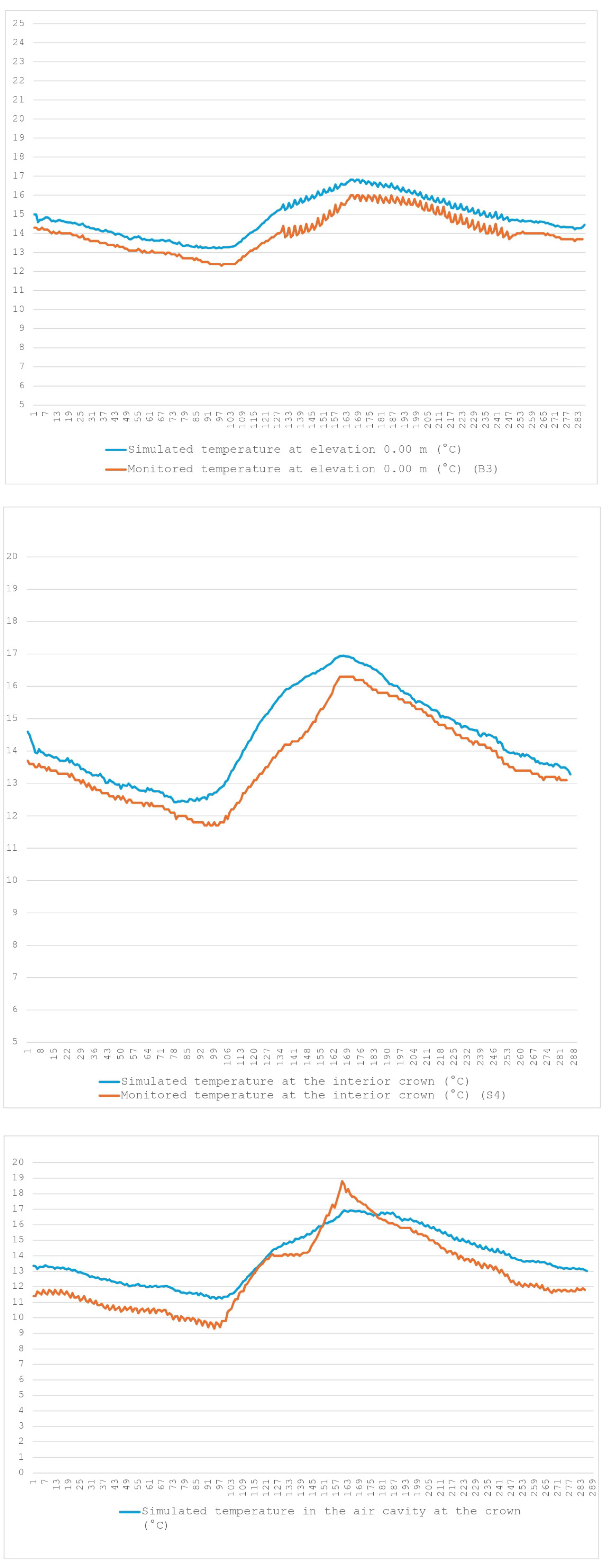
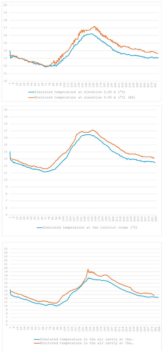
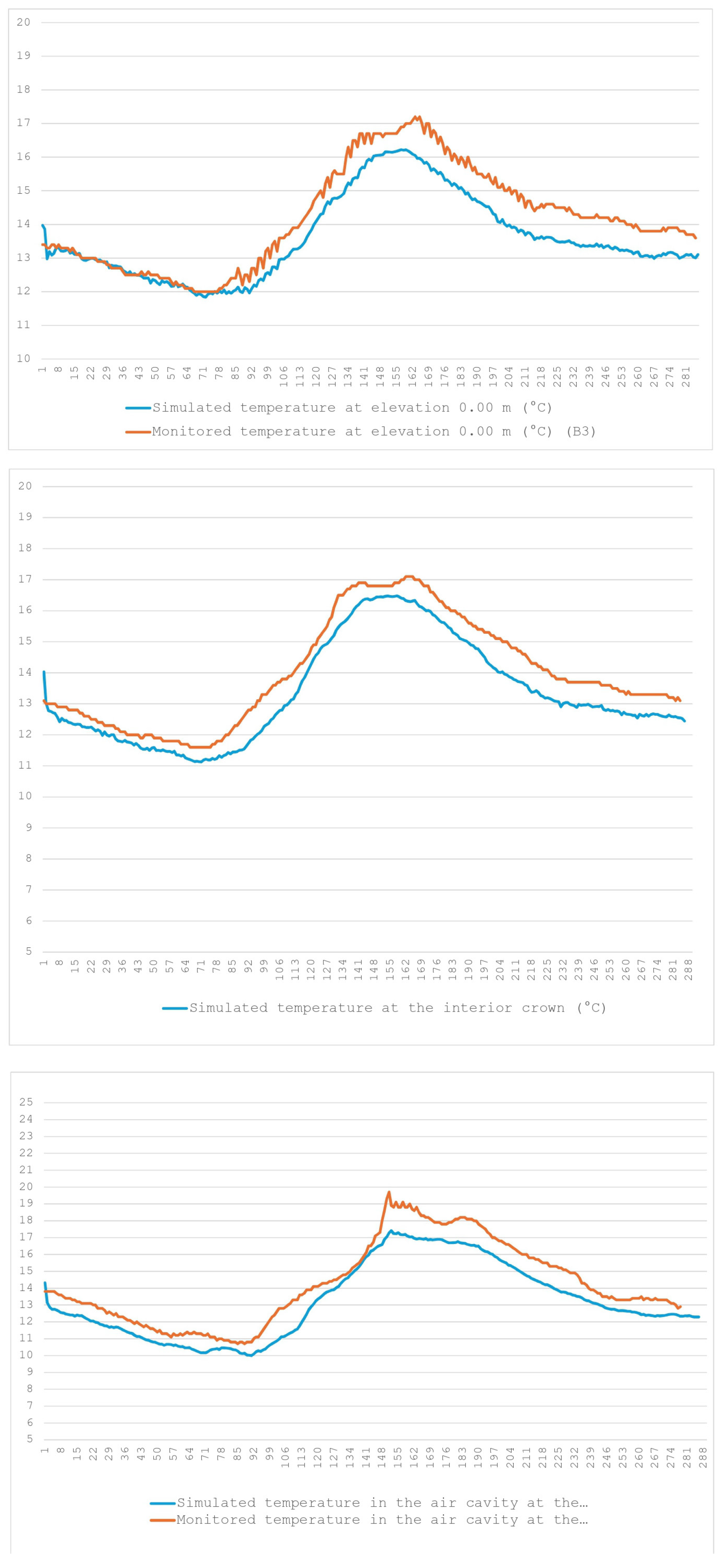
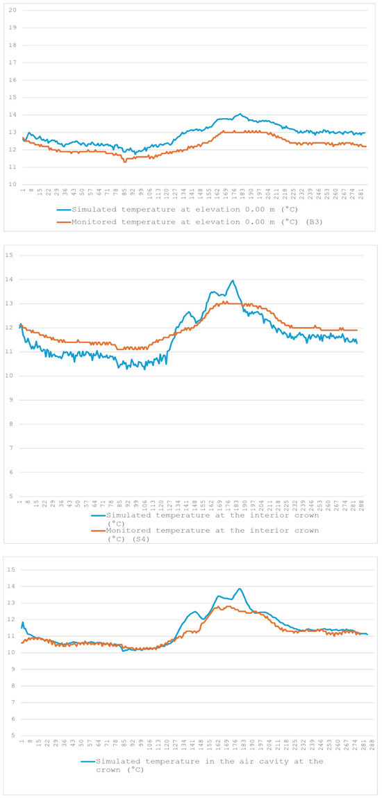
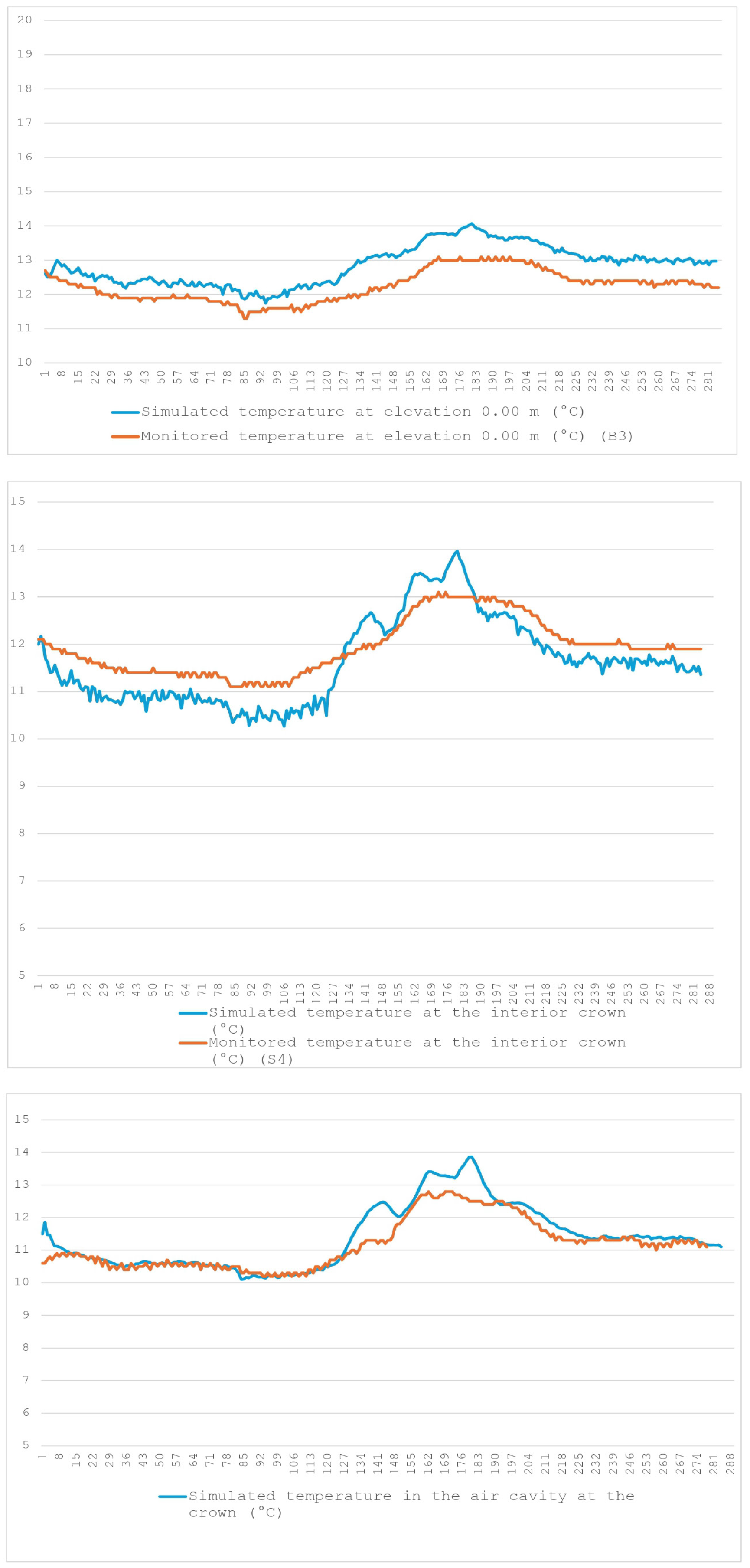
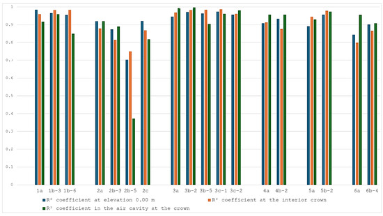
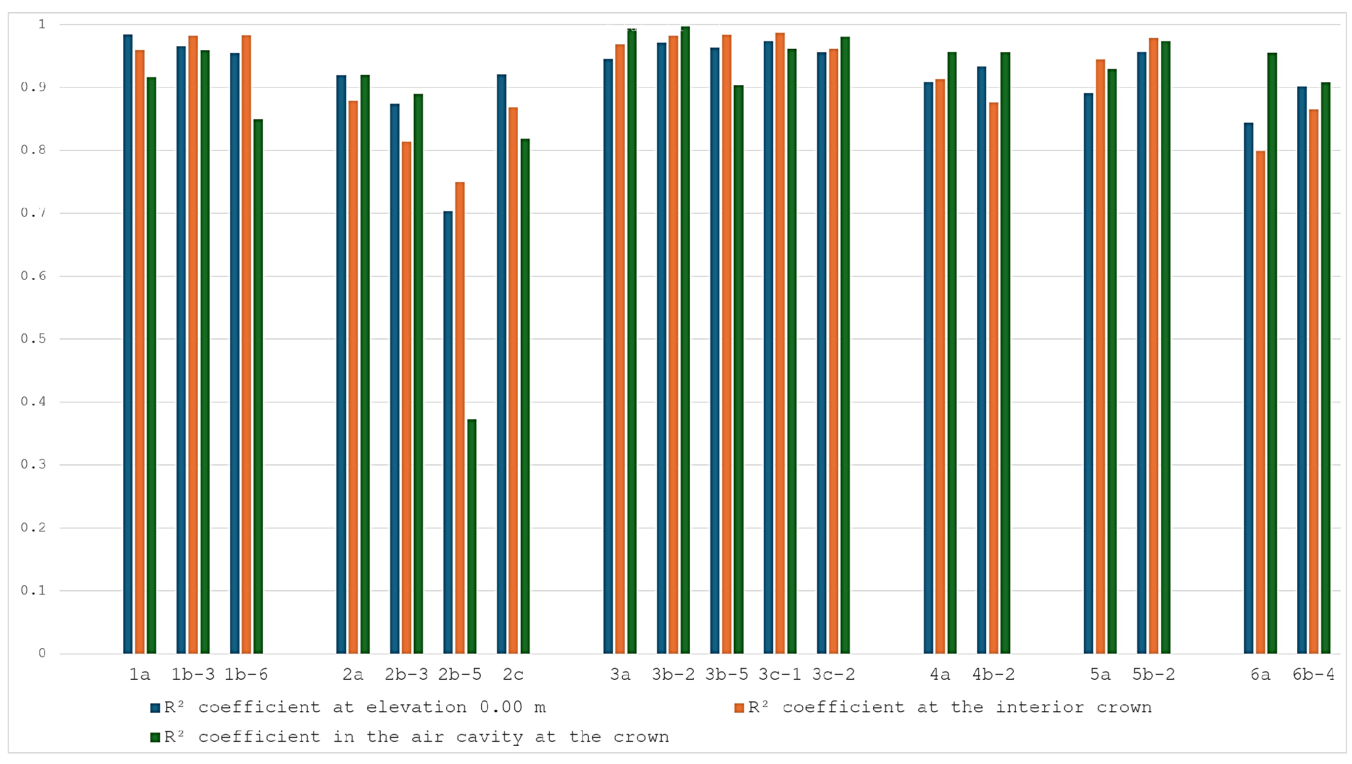
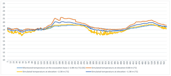
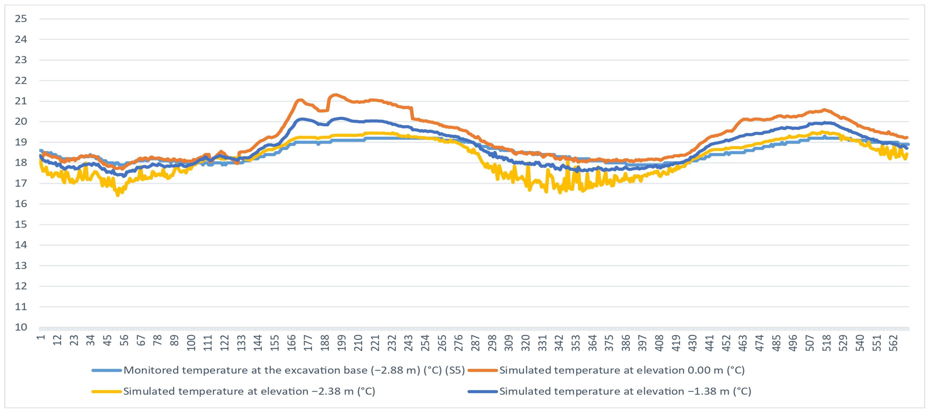
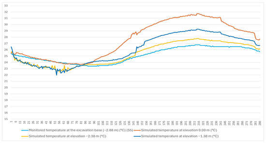
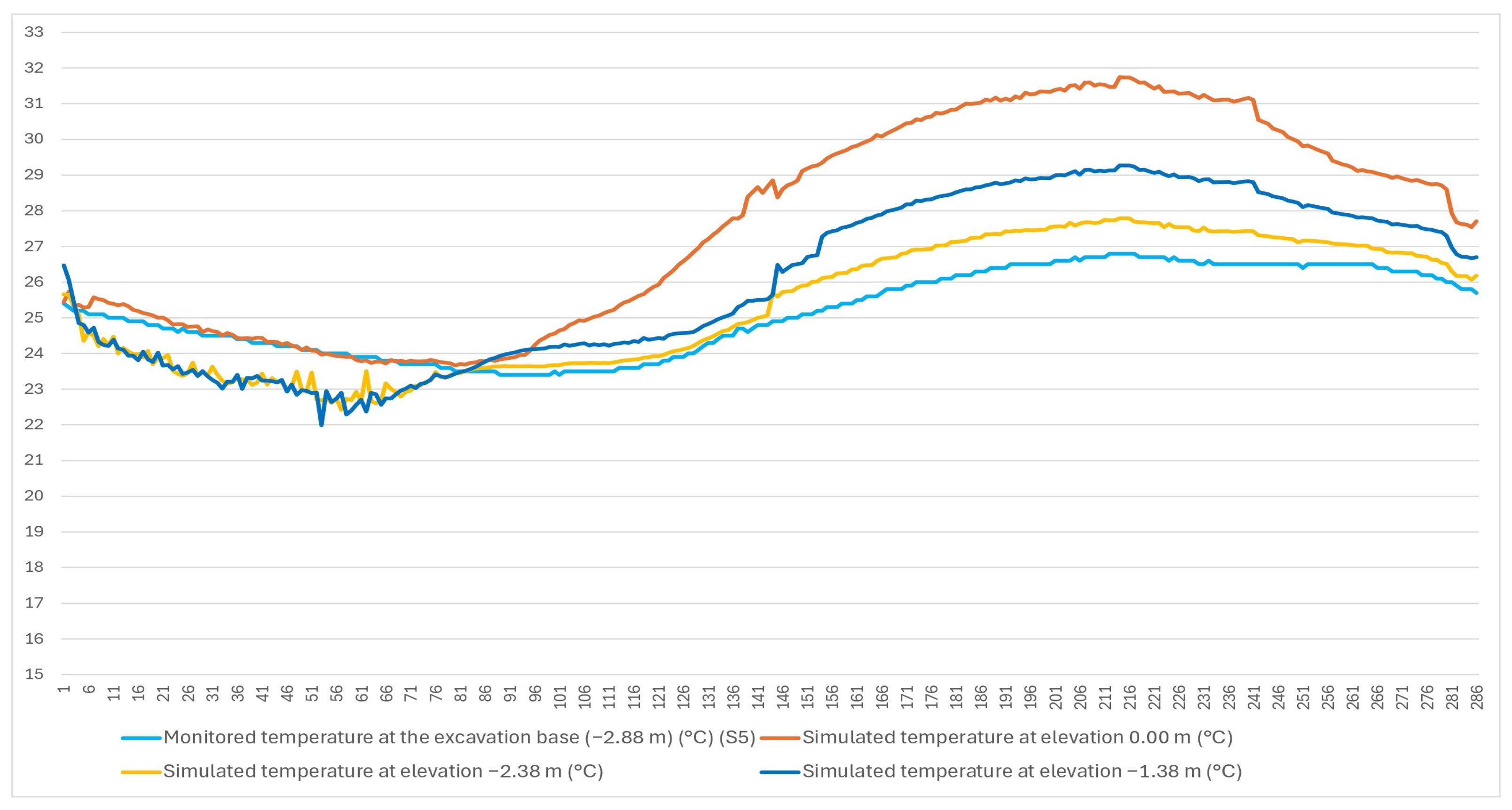
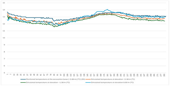
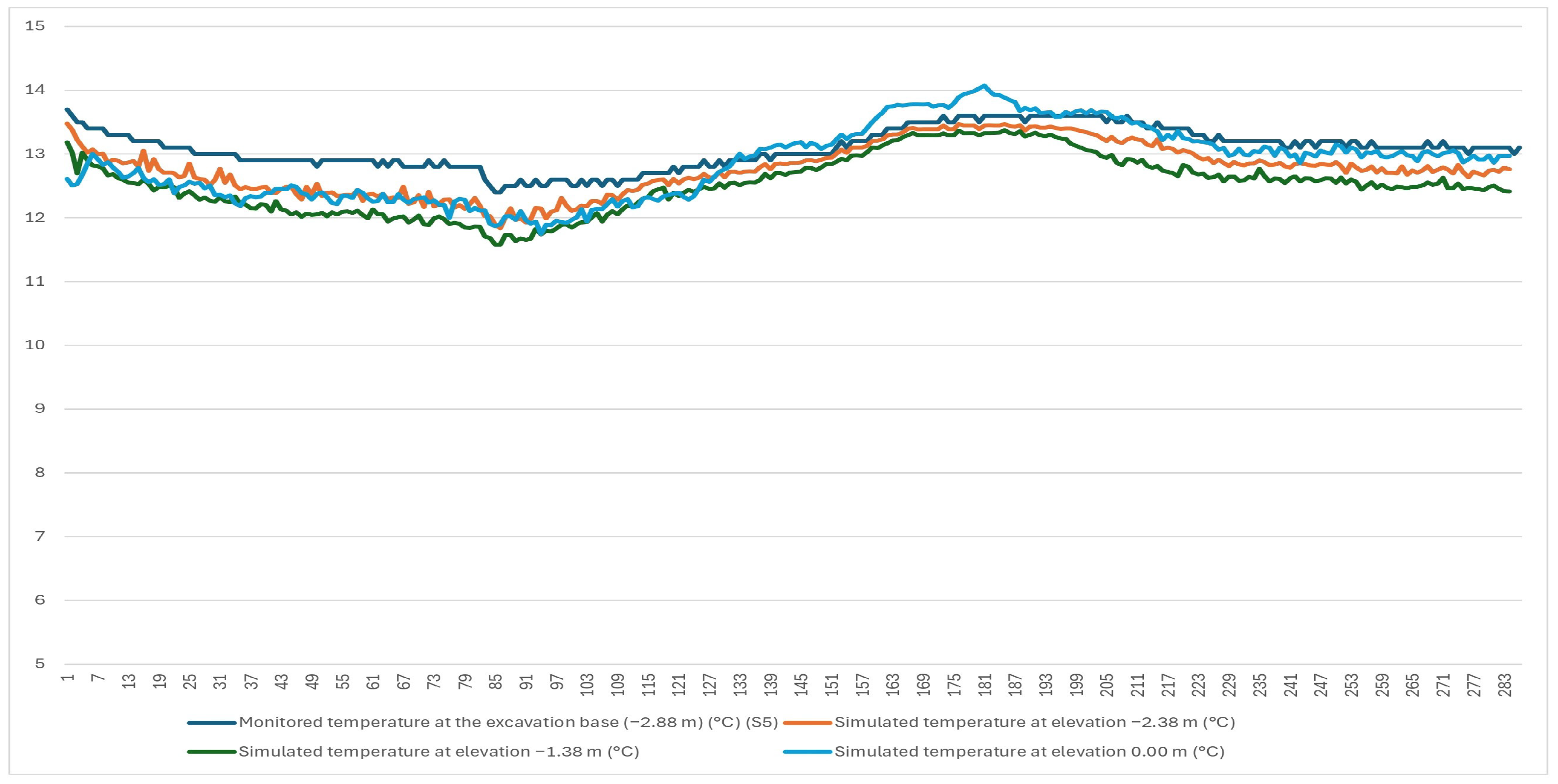
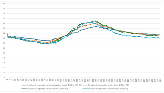
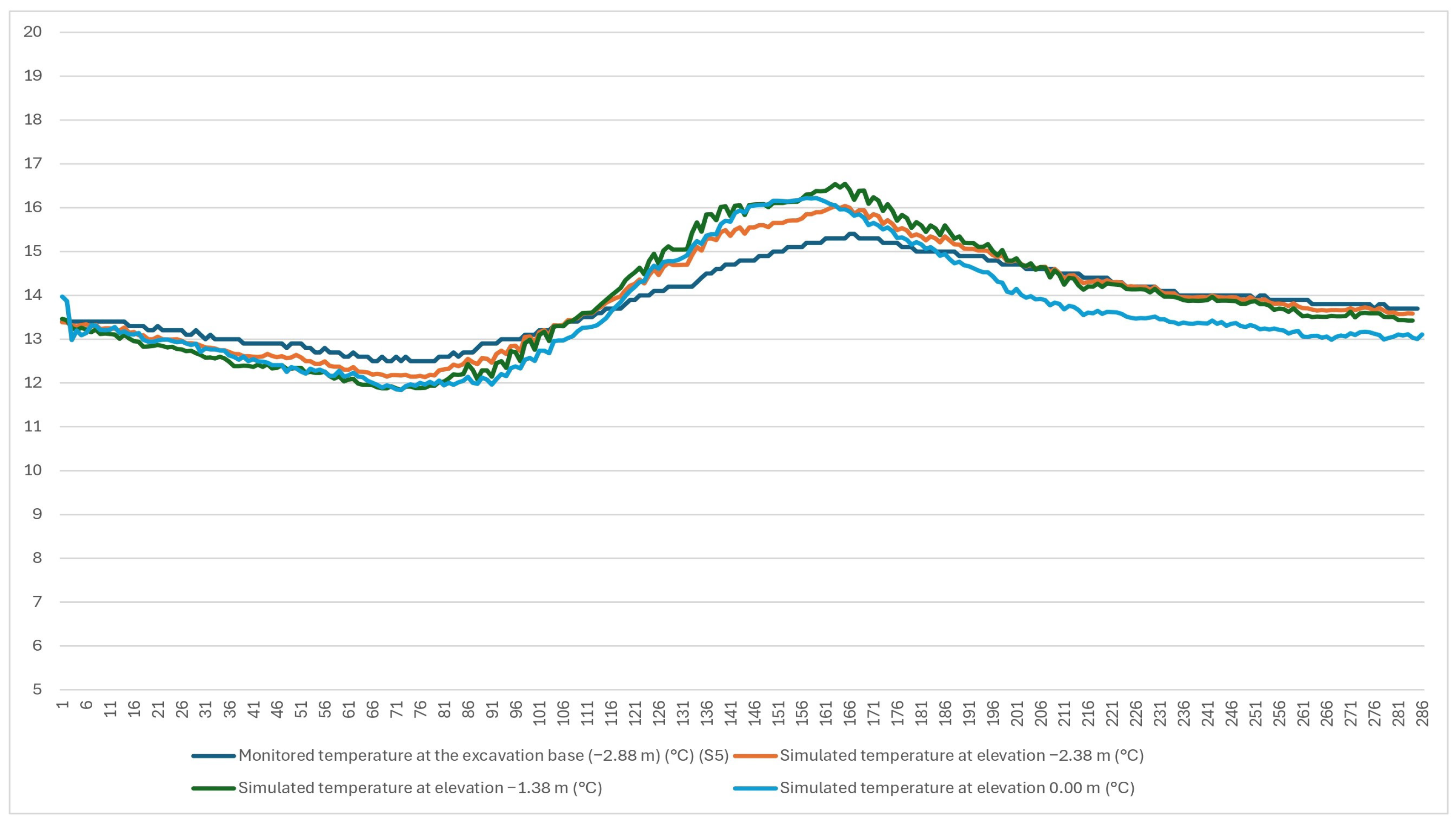
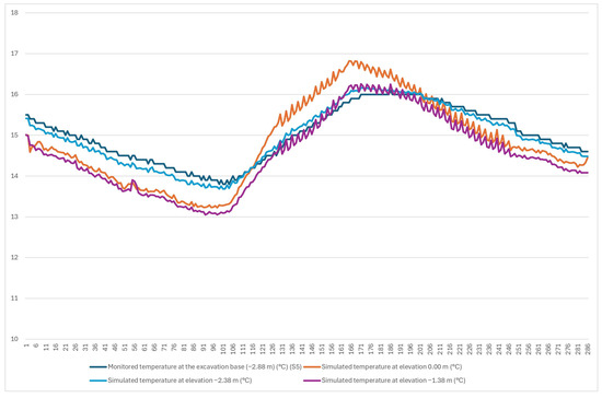
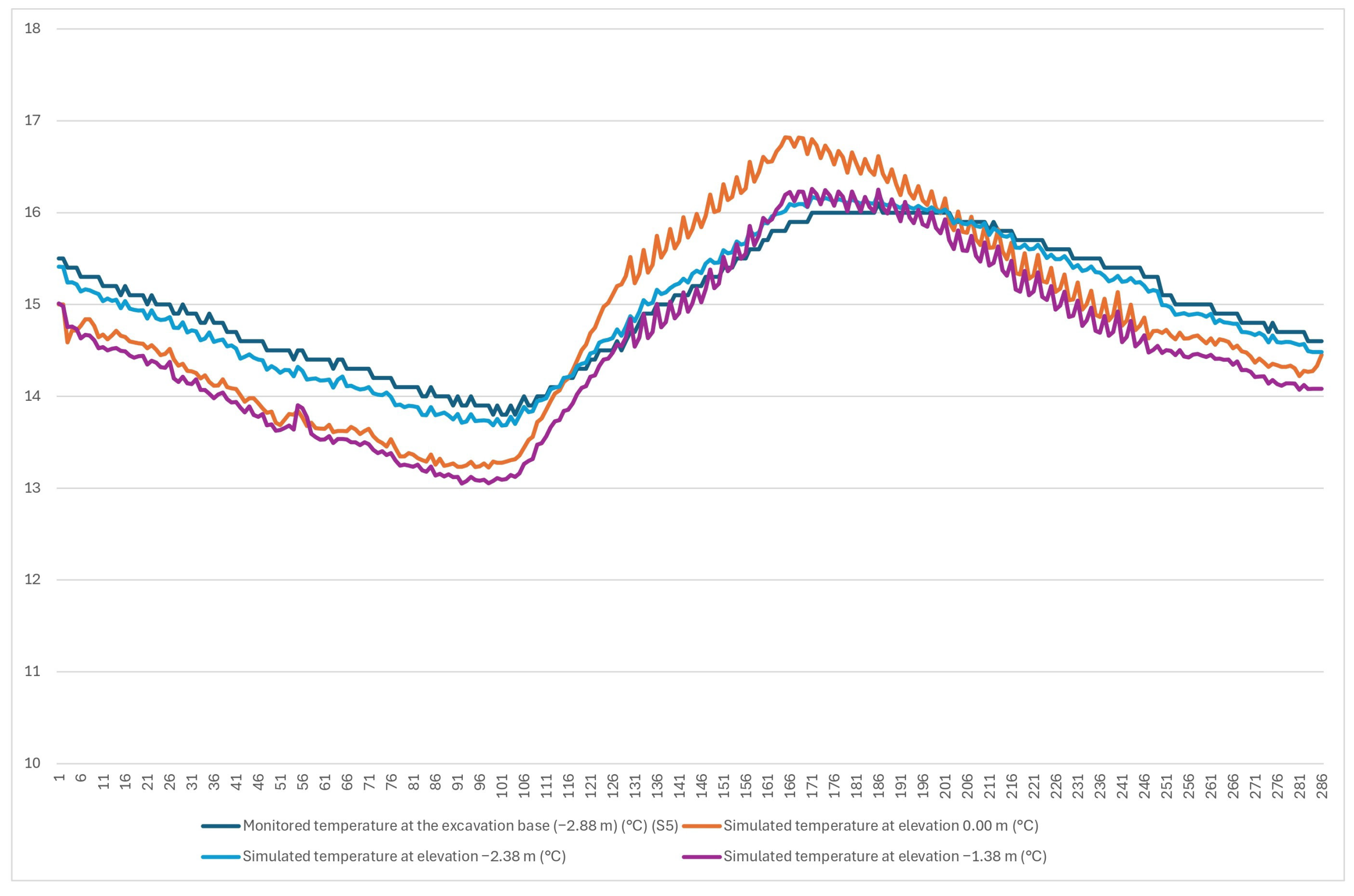

Disclaimer/Publisher’s Note: The statements, opinions and data contained in all publications are solely those of the individual author(s) and contributor(s) and not of MDPI and/or the editor(s). MDPI and/or the editor(s) disclaim responsibility for any injury to people or property resulting from any ideas, methods, instructions or products referred to in the content. |
© 2026 by the authors. Licensee MDPI, Basel, Switzerland. This article is an open access article distributed under the terms and conditions of the Creative Commons Attribution (CC BY) license.